WO2019186689A1 - Unité siège pour aéronef - Google Patents
Unité siège pour aéronef Download PDFInfo
- Publication number
- WO2019186689A1 WO2019186689A1 PCT/JP2018/012405 JP2018012405W WO2019186689A1 WO 2019186689 A1 WO2019186689 A1 WO 2019186689A1 JP 2018012405 W JP2018012405 W JP 2018012405W WO 2019186689 A1 WO2019186689 A1 WO 2019186689A1
- Authority
- WO
- WIPO (PCT)
- Prior art keywords
- seat
- backrest
- sheet
- state
- partition plate
- Prior art date
Links
Images


Classifications
-
- B—PERFORMING OPERATIONS; TRANSPORTING
- B64—AIRCRAFT; AVIATION; COSMONAUTICS
- B64D—EQUIPMENT FOR FITTING IN OR TO AIRCRAFT; FLIGHT SUITS; PARACHUTES; ARRANGEMENTS OR MOUNTING OF POWER PLANTS OR PROPULSION TRANSMISSIONS IN AIRCRAFT
- B64D11/00—Passenger or crew accommodation; Flight-deck installations not otherwise provided for
- B64D11/06—Arrangements of seats, or adaptations or details specially adapted for aircraft seats
- B64D11/0639—Arrangements of seats, or adaptations or details specially adapted for aircraft seats with features for adjustment or converting of seats
- B64D11/0641—Seats convertible into beds
-
- B—PERFORMING OPERATIONS; TRANSPORTING
- B64—AIRCRAFT; AVIATION; COSMONAUTICS
- B64D—EQUIPMENT FOR FITTING IN OR TO AIRCRAFT; FLIGHT SUITS; PARACHUTES; ARRANGEMENTS OR MOUNTING OF POWER PLANTS OR PROPULSION TRANSMISSIONS IN AIRCRAFT
- B64D11/00—Passenger or crew accommodation; Flight-deck installations not otherwise provided for
- B64D11/06—Arrangements of seats, or adaptations or details specially adapted for aircraft seats
- B64D11/0602—Seat modules, i.e. seat systems including furniture separate from the seat itself
- B64D11/0604—Seat modules, i.e. seat systems including furniture separate from the seat itself including a bed, e.g. cocoon type passenger seat modules
-
- B—PERFORMING OPERATIONS; TRANSPORTING
- B64—AIRCRAFT; AVIATION; COSMONAUTICS
- B64D—EQUIPMENT FOR FITTING IN OR TO AIRCRAFT; FLIGHT SUITS; PARACHUTES; ARRANGEMENTS OR MOUNTING OF POWER PLANTS OR PROPULSION TRANSMISSIONS IN AIRCRAFT
- B64D11/00—Passenger or crew accommodation; Flight-deck installations not otherwise provided for
- B64D11/06—Arrangements of seats, or adaptations or details specially adapted for aircraft seats
- B64D11/0602—Seat modules, i.e. seat systems including furniture separate from the seat itself
- B64D11/0605—Seat modules, i.e. seat systems including furniture separate from the seat itself including tables or desks
-
- B—PERFORMING OPERATIONS; TRANSPORTING
- B64—AIRCRAFT; AVIATION; COSMONAUTICS
- B64D—EQUIPMENT FOR FITTING IN OR TO AIRCRAFT; FLIGHT SUITS; PARACHUTES; ARRANGEMENTS OR MOUNTING OF POWER PLANTS OR PROPULSION TRANSMISSIONS IN AIRCRAFT
- B64D11/00—Passenger or crew accommodation; Flight-deck installations not otherwise provided for
- B64D11/06—Arrangements of seats, or adaptations or details specially adapted for aircraft seats
- B64D11/0606—Arrangements of seats, or adaptations or details specially adapted for aircraft seats with privacy shells, screens, separators or the like
-
- B—PERFORMING OPERATIONS; TRANSPORTING
- B64—AIRCRAFT; AVIATION; COSMONAUTICS
- B64D—EQUIPMENT FOR FITTING IN OR TO AIRCRAFT; FLIGHT SUITS; PARACHUTES; ARRANGEMENTS OR MOUNTING OF POWER PLANTS OR PROPULSION TRANSMISSIONS IN AIRCRAFT
- B64D11/00—Passenger or crew accommodation; Flight-deck installations not otherwise provided for
- B64D11/06—Arrangements of seats, or adaptations or details specially adapted for aircraft seats
- B64D11/0639—Arrangements of seats, or adaptations or details specially adapted for aircraft seats with features for adjustment or converting of seats
- B64D11/064—Adjustable inclination or position of seats
-
- B—PERFORMING OPERATIONS; TRANSPORTING
- B64—AIRCRAFT; AVIATION; COSMONAUTICS
- B64D—EQUIPMENT FOR FITTING IN OR TO AIRCRAFT; FLIGHT SUITS; PARACHUTES; ARRANGEMENTS OR MOUNTING OF POWER PLANTS OR PROPULSION TRANSMISSIONS IN AIRCRAFT
- B64D11/00—Passenger or crew accommodation; Flight-deck installations not otherwise provided for
- B64D11/06—Arrangements of seats, or adaptations or details specially adapted for aircraft seats
- B64D11/0601—Arrangement of seats for non-standard seating layouts, e.g. seats staggered horizontally or vertically, arranged in an angled or fishbone layout, or facing in other directions than the direction of flight
Definitions
- the present invention relates to an aircraft seat unit.
- a seat structure that can selectively change between a seat seated on an aircraft and a backrest standing upright, and a backrest reclining state that can be used as a bed after being reclined.
- a class seat Known as a class seat.
- Patent Document 1 there is also known an aircraft seat structure capable of moving up and down partition plates between sheets arranged in the traveling direction. According to such a configuration, for example, when another person sits on each seat, a private space can be secured for each seat by raising the partition plate. On the other hand, when two passengers such as a family sit next to each other, one partition can be secured by lowering the partition plate, which makes it possible to use them according to the passengers. ing.
- an object of the present invention is to provide a seat unit for an aircraft that can deal with diversification of passengers and can effectively use the space in the cabin.
- an aircraft seat unit comprises: The first backrest is pivotable with respect to the first seat, and it is possible to change the form between a seat state in which a passenger can sit and a bed state in which the first seat and the first backrest are flat.
- a first sheet The seat is disposed adjacent to the first seat, the second backrest is pivotable with respect to the second seat, the seat state in which a passenger can sit, and the first seat and the first backrest are flat.
- a second sheet capable of changing the form of the bed state An intermediate portion disposed between the first sheet and the second sheet; In the bed state, the intermediate portion is adjacent to the first backrest and the second backrest in a state in which the height of the upper surface is substantially matched,
- the intermediate portion has a partition plate that can be raised and lowered, When the partition plate is housed in the intermediate portion, the upper end of the partition plate substantially coincides with the height of the upper surface of the intermediate portion or is lower than that, and when the partition plate is raised, The upper end of the partition plate is movable upward from at least the first backrest or the second backrest in the seat state. It is characterized by that.
- an aircraft seat unit that can cope with diversification of passengers and that can effectively use the space in the cabin.
- FIG. 1 is a top view showing an overhead view of an aircraft cabin equipped with an aircraft seat unit according to the present embodiment. It is the perspective view which looked at the seat unit 10 for aircrafts from diagonally upward. It is the perspective view which looked at the seat unit 10 for aircrafts from the front upper direction. It is the top view which looked at the seat unit 10 for aircrafts from right above, and is a figure which shows a seat state. It is the top view which looked at the seat unit 10 for aircrafts from right above, and is a figure which shows a bed state.
- FIG. 4 is a cross-sectional view taken along the line AA of FIG. 3 and shows a state where the partition plate is raised to a maximum position (shielded state).
- FIG. 4 is a cross-sectional view taken along the line AA in FIG. 3 and shows a state in which the partition plate is accommodated in the intermediate portion (open state). It is a figure which shows the usage example of a sheet unit.
- the heights substantially coincide means that the height difference is within 2 cm (preferably within 1 cm).
- “Front” and “rear” refer to the direction of travel of the aircraft and the direction opposite to the direction of travel, respectively.
- FIG. 1 is a top view showing an overhead view of an aircraft cabin equipped with an aircraft seat unit according to the present embodiment.
- the left side in the drawing is the front side of the aircraft, and the right side is the rear side of the aircraft.
- a plurality of aircraft seat units 10 are arranged in a row on the floor 2, and single seats 20 are arranged in a row on the windows on both sides.
- FIG. 2 is a perspective view of the aircraft seat unit 10 as viewed obliquely from above.
- FIG. 3 is a perspective view of the aircraft seat unit 10 as viewed from the front upper side.
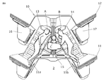
- FIG. 4 is a top view of the aircraft seat unit 10 as viewed from directly above, showing a seat state.
- FIG. 5 is a top view of the aircraft seat unit 10 as viewed from directly above, showing a bed state.
- the aircraft seat unit 10 is disposed adjacent to each other on the front wall 11 and the rear wall 12 standing in parallel with the floor 2 and on the floor 2 between the front wall 11 and the rear wall 12.
- a second side table 17 arranged on the side of the second sheet 14.
- the front wall 11 and the rear wall 12 have a common shape. Accordingly, the rear wall 12 of the front seat unit 10 can be shared as the front wall 11 of the rear seat unit 10 adjacent thereto.
- the seat unit 10 has a front wall 11 and a rear wall 12.
- the first seat 13 and the second seat 14 and the rear wall 12 are supplied as a set of seat units from an interior manufacturer, and these are arranged in the front and rear and assembled to the aircraft 1 so that the rear wall 12 Is shared as the front wall 11.
- the front wall 11 has trapezoidal columnar protrusions 11a and 11b protruding forward on both sides thereof.
- the rear wall 12 has trapezoidal columnar protrusions 12a and 12b protruding forward on both sides thereof.
- the inside of the protrusions 12a and 12b of the rear wall 12 is hollow, and the first side table 16 is placed on the upper surface of the protrusion 12a, and the second side table 17 is placed on the upper surface of the protrusion 12b. The same applies to the front wall 11.
- the front wall 11 and the rear wall 12 have a substantially W shape when viewed from above.
- the axis X1 of the first seat 13 and the axis X2 of the second seat 14 are angled at the same angle on the opposite side with respect to the traveling direction D of the aircraft 1.
- the dimensions along the traveling direction D of the first sheet 13 and the second sheet 14 in the bed state (FIG. 5) can be suppressed, and a large number of seat units can be mounted on the aircraft 1.
- a substantially triangular prism-shaped space is generated between the first sheet 13 and the second sheet 14.
- An intermediate portion 15 is provided by using this space to make effective use of the space.
- the intermediate portion 15 is disposed in a three substantially prismatic space between the front wall 11, the first sheet 13, and the second sheet 14.
- seat 14 is common, you may make both differ.
- seat 14 can also be used as the sheet
- the first seat 13 has a first seat 13a and a first backrest 13b.
- the first backrest 13b is pivotally connected to the rear end of the first seat 13a.
- the reclining mechanism 13c (see FIG. 6 described later) is driven and controlled, and at the same time the first backrest 13b falls backward with respect to the first seat 13a, the first seat 13a Slides horizontally forward, and the upper surfaces of the first seat 13a and the first backrest 13b become flat horizontally.
- This is called a bed state (see FIG. 5).
- a part of the first seat 13a enters the inside of the protruding portion 11a. That is, the inside of the protruding portion 11a becomes a part of the use space of the user, and the user can lie on the first sheet 13 with his legs extended.
- the first back 13b rises with respect to the first seat 13a, and at the same time, the first seat 13a slides backward, and the first seat 13a In contrast, the first backrest 13b is angled. This is called a sheet state (see FIGS. 3 and 4).
- the reclining mechanism 13c may slightly lift the front end of the first seat 13a. As a result, the user can sit on the first seat 13a in an easy posture.
- the second seat 14 has a second seat 14a and a second backrest 14b.
- the second backrest 14b is pivotally connected to the rear end of the second seat 14a.
- the reclining mechanism 14c (see FIG. 6 described later) is driven and controlled, and the second backrest 14b falls backward with respect to the second seat 14a, and at the same time, the second seat 14a.
- a part of the second seat 14a enters the inside of the protruding portion 11b. That is, the inside of the protruding portion 11b becomes a part of the use space of the user, and the user can lie on the second sheet 14 with his legs extended.
- the second backrest 14b rises with respect to the second seat 14a, and at the same time, the second seat 14a slides backward, and the second seat 14a In contrast, the second backrest 14b is angled. This is called a sheet state (see FIGS. 3 and 4).
- the reclining mechanism 14c may slightly lift the front end of the second seat 14a. As a result, the user can sit on the second seat 14a in an easy posture.
- the reclining mechanisms 13c and 14c for example, the technology disclosed in JP-T-2010-520117 can be used.
- the intermediate portion 15 is disposed between a pedestal 15a having a triangular prism shape disposed on the first sheet 13 side, a pedestal 15b having a triangular prism shape disposed on the second sheet 14 side, and the pedestals 15a and 15b. It has the support part 15c which is a rectangular parallelepiped shape, and the partition plate 15d supported by the support part 15c.
- the support portion 15 c and the partition plate 15 d extend from the back surface of the front wall 11 to the front surface of the rear wall 12.
- the end portion of the partition plate 15d is engaged with the vertical groove 11c on the back surface of the front wall 11 and the vertical groove 12c on the back surface of the rear wall 12, and can be moved up and down by being guided by these. ing.
- FIG. 6 and 7 are AA cross-sectional views of FIG.
- pedestals 15a and 15b are fixed to the floor, and the upper surface thereof is stretched with a cushioning material like the seat.
- the support part 15c is arrange
- Each of the bases 15a and 15b can be composed of a plurality of members.
- the support portion 15c on which a cushioning material is stretched has a slit 15f that opens at the center of the upper surface.
- a partition plate 15d is slidably disposed in the slit 15f.
- the partition plate 15d is preferably made of, for example, a translucent or opaque resin.
- the partition plate 15d in the shielded state is the line of sight of the user seated on the first seat 13a or the second seat 14a in the seat state (usually 10 cm or more below the upper end of the first backrest 13b or the second backrest 14b). It becomes higher. Thereby, the private space of the user sitting on the 1st sheet
- a user or an occupant manually or electrically slides the support portion 15c downward with respect to the bases 15a and 15b, and slides the partition plate 15d downward with respect to the support portion 15c to be accommodated therein. be able to.
- Such a state is called an open state.
- the open state as shown in FIG. 7, the height positions of the upper surfaces of the bases 15a and 15b and the upper surface of the support portion 15c substantially coincide. Further, the height of the upper surface of the support portion 15c and the height of the upper end of the partition plate 15d are substantially the same. That is, as shown in FIG. 7, the entire upper surface of the intermediate portion 15 has a uniform height.
- the height of the first backrest 13 b and the second backrest 14 b is the height of the upper surface of the intermediate portion 15. Approximate with height.
- FIG. 8 shows an example of use of the space obtained in the seat unit 10 in this way.
- the user A lies on the first sheet 13 in the bed state
- the user B lies on the second sheet 14 in the bed state
- the infant C lies on the intermediate portion 15 with the partition plate 15d and the support portion 15c lowered.
- foot can be accommodated in protrusion part 11a, 11b of the front wall 11 as shown with a dotted line, a user can extend a leg
- the seat unit for an aircraft it is not necessary to secure an adult seat for the infant C, and the economic burden on the users A and B accompanying the infant C can be reduced.
- the upper end of the partition plate 15d in the shielded state can be lifted high while keeping the intermediate portion 15 low. That is, assuming that there is no support portion 15c, the height of the upper surface of the intermediate portion 15 (the height of the upper end of the partition plate 15d) is substantially equal to the height of the upper surface of the first backrest 13b or the second backrest 14b in the bed state. In this case, the height of the partition plate 15d is only twice as high as that of the intermediate portion 15 in the shielded state. In such a case, the height of the partition plate 15d in the shielded state is below the line of sight of the user sitting on the seat, so that a private space cannot be secured on the first seat 13 side and the second seat 14 side.
- a two-step lifting structure in which the support portion 15c is provided in the intermediate portion 15, the support portion 15c is slid with respect to the bases 15a and 15b, and the partition plate 15d is slid with respect to the support portion 15c.
- the upper end of the partition plate 15 d can be raised to a height position that is approximately three times the height of the intermediate portion 15.
- it can also be set as the 3 steps
- the intermediate section 15 can be used not only for infants but also for the purpose of placing important musical instruments within reach of, for example, performers when boarding.
- the intermediate portion 15 can be used to place a shogi board, a chess board, or the like when a passenger of the first seat 13 and a passenger of the second seat 14 want to play a shogi or chess battle.
- the upper end of the partition plate 15 d in the shielding state may be below the upper surface of the intermediate portion 15.
Abstract
Selon l'invention, une unité siège pour un aéronef comporte une section intermédiaire (15) disposée entre un premier siège (13) et un second siège (14). Dans un état de lit, la section intermédiaire (15) est adjacente à un premier dossier (13b) et à un second dossier (13b) tandis que la hauteur de la surface supérieure de la section intermédiaire (15) coïncide sensiblement avec la hauteur du premier dossier (13b) et du second dossier (13b). La section intermédiaire (15) comporte une plaque de séparation (15d) mobile verticalement. Dans un état dans lequel la section intermédiaire (15) contient la plaque de séparation (15d), l'extrémité supérieure de la plaque de séparation (15d) est située à ou sous la hauteur de la surface supérieure de la section intermédiaire (15), et lorsque la plaque de séparation (15d) est relevée, l'extrémité supérieure de la plaque de séparation (15d) peut se déplacer jusqu'à une position au-dessus du niveau des yeux d'un utilisateur assis dans un premier siège (13a) ou un second siège (13b) qui est au moins dans un état de siège.
Priority Applications (4)
| Application Number | Priority Date | Filing Date | Title |
|---|---|---|---|
| PCT/JP2018/012405 WO2019186689A1 (fr) | 2018-03-27 | 2018-03-27 | Unité siège pour aéronef |
| EP18912749.1A EP3778398A4 (fr) | 2018-03-27 | 2018-03-27 | Unité siège pour aéronef |
| US16/981,523 US20210009271A1 (en) | 2018-03-27 | 2018-03-27 | Seat unit for aircraft |
| JP2020510232A JP6975318B2 (ja) | 2018-03-27 | 2018-03-27 | 航空機用のシートユニット |
Applications Claiming Priority (1)
| Application Number | Priority Date | Filing Date | Title |
|---|---|---|---|
| PCT/JP2018/012405 WO2019186689A1 (fr) | 2018-03-27 | 2018-03-27 | Unité siège pour aéronef |
Publications (1)
| Publication Number | Publication Date |
|---|---|
| WO2019186689A1 true WO2019186689A1 (fr) | 2019-10-03 |
Family
ID=68062595
Family Applications (1)
| Application Number | Title | Priority Date | Filing Date |
|---|---|---|---|
| PCT/JP2018/012405 WO2019186689A1 (fr) | 2018-03-27 | 2018-03-27 | Unité siège pour aéronef |
Country Status (4)
| Country | Link |
|---|---|
| US (1) | US20210009271A1 (fr) |
| EP (1) | EP3778398A4 (fr) |
| JP (1) | JP6975318B2 (fr) |
| WO (1) | WO2019186689A1 (fr) |
Families Citing this family (1)
| Publication number | Priority date | Publication date | Assignee | Title |
|---|---|---|---|---|
| WO2019179638A1 (fr) * | 2018-03-23 | 2019-09-26 | Adient Aerospace Llc | Unité siège et agencement de siège passager disposé à l'intérieur d'une cabine de véhicule |
Citations (7)
| Publication number | Priority date | Publication date | Assignee | Title |
|---|---|---|---|---|
| JP2010501447A (ja) * | 2006-10-12 | 2010-01-21 | ビー イー エアロスペイス,インク. | 移動および回転可能な乗客シート |
| JP2010520117A (ja) | 2007-03-08 | 2010-06-10 | プレミアム エアクラフト インテリアーズ ユーケー リミテッド | 航空機座席 |
| JP2011506165A (ja) * | 2007-12-06 | 2011-03-03 | ビー イー エアロスペイス,インク. | 航空機のシート配置構造及びシート |
| JP2012521328A (ja) * | 2009-03-23 | 2012-09-13 | エア ニュージーランド リミティド | 輸送手段の乗客用座席配置の改良 |
| JP2015511557A (ja) * | 2012-03-14 | 2015-04-20 | ビーイー・エアロスペース・インコーポレーテッド | 組み合わせベッドを備える航空機の乗客用スイート |
| WO2017168746A1 (fr) | 2016-04-01 | 2017-10-05 | 株式会社ジャムコ | Structure de siège d'aéronef |
| WO2018051496A1 (fr) * | 2016-09-16 | 2018-03-22 | 株式会社ジャムコ | Unité de siège d'aéronef et structure à sièges multiples |
Family Cites Families (8)
| Publication number | Priority date | Publication date | Assignee | Title |
|---|---|---|---|---|
| NZ336551A (en) * | 1997-02-20 | 2001-11-30 | Singapore Airlines Ltd | Reclining seat for aircraft with armrest that is retracted when the seat is moved from an upright to a reclined position |
| US7578470B2 (en) * | 2006-04-21 | 2009-08-25 | Be Aerospace, Inc. | Passenger seating arrangement |
| GB0903744D0 (en) * | 2009-03-04 | 2009-04-15 | Virgin Atlantic Airways Ltd | A seating insallation for a passenger vehicle |
| FR2953168B1 (fr) * | 2009-12-02 | 2012-01-06 | Eads Sogerma | Siege convertible en couchette |
| FR3003540B1 (fr) * | 2013-03-25 | 2015-05-29 | Eads Sogerma | Agencement de sieges convertibles en couchettes |
| FR3055128A1 (fr) * | 2016-08-17 | 2018-02-23 | Zodiac Seats France | Agencement de sieges permettant d'augmenter l'intimite des passagers, notamment d'un avion |
| FR3059951B1 (fr) * | 2016-12-14 | 2019-05-17 | Zodiac Seats France | Arrangement de sieges individuels pour passagers d'un avion |
| US11008105B2 (en) * | 2017-10-03 | 2021-05-18 | Singapore Airlines Limited | Aircraft seat |
-
2018
- 2018-03-27 JP JP2020510232A patent/JP6975318B2/ja active Active
- 2018-03-27 EP EP18912749.1A patent/EP3778398A4/fr active Pending
- 2018-03-27 US US16/981,523 patent/US20210009271A1/en not_active Abandoned
- 2018-03-27 WO PCT/JP2018/012405 patent/WO2019186689A1/fr unknown
Patent Citations (7)
| Publication number | Priority date | Publication date | Assignee | Title |
|---|---|---|---|---|
| JP2010501447A (ja) * | 2006-10-12 | 2010-01-21 | ビー イー エアロスペイス,インク. | 移動および回転可能な乗客シート |
| JP2010520117A (ja) | 2007-03-08 | 2010-06-10 | プレミアム エアクラフト インテリアーズ ユーケー リミテッド | 航空機座席 |
| JP2011506165A (ja) * | 2007-12-06 | 2011-03-03 | ビー イー エアロスペイス,インク. | 航空機のシート配置構造及びシート |
| JP2012521328A (ja) * | 2009-03-23 | 2012-09-13 | エア ニュージーランド リミティド | 輸送手段の乗客用座席配置の改良 |
| JP2015511557A (ja) * | 2012-03-14 | 2015-04-20 | ビーイー・エアロスペース・インコーポレーテッド | 組み合わせベッドを備える航空機の乗客用スイート |
| WO2017168746A1 (fr) | 2016-04-01 | 2017-10-05 | 株式会社ジャムコ | Structure de siège d'aéronef |
| WO2018051496A1 (fr) * | 2016-09-16 | 2018-03-22 | 株式会社ジャムコ | Unité de siège d'aéronef et structure à sièges multiples |
Non-Patent Citations (1)
| Title |
|---|
| See also references of EP3778398A4 * |
Also Published As
| Publication number | Publication date |
|---|---|
| EP3778398A4 (fr) | 2021-10-20 |
| EP3778398A1 (fr) | 2021-02-17 |
| US20210009271A1 (en) | 2021-01-14 |
| JPWO2019186689A1 (ja) | 2021-01-07 |
| JP6975318B2 (ja) | 2021-12-01 |
Similar Documents
| Publication | Publication Date | Title |
|---|---|---|
| US11787545B2 (en) | Platform first class | |
| US5954401A (en) | Reclining seat and ottoman system for aircraft including amenity cabinet | |
| US9126689B2 (en) | Vehicle passenger seating | |
| CN109018371B (zh) | 用于交通工具客舱的座椅单元 | |
| JP4313441B2 (ja) | シートユニット | |
| CN104271446B (zh) | 具有独立的座位区域的豪华舱飞行器乘客套间 | |
| EP3774484B1 (fr) | Configuration de l'ensemble de sièges pour véhicules | |
| US8342450B2 (en) | Seating arrangement of a vehicle compartment | |
| US20160031561A1 (en) | Seating Arrangement, Seat Unit, Tray Table and Seating System | |
| US9327837B2 (en) | Modular airplane seat unit | |
| JP2016521157A (ja) | ドロップダウン式アームレストアセンブリを備えた乗客座席 | |
| JP7026224B2 (ja) | 航空機用のシートユニット | |
| WO2011077366A1 (fr) | Améliorations relatives à des sièges de passagers de véhicule | |
| WO2019186689A1 (fr) | Unité siège pour aéronef | |
| US20120112500A1 (en) | Vehicle Seating Apparatus | |
| US20150210396A1 (en) | Seat arrangement, aircraft cabin as well as armrest and seat or seat group for use therein | |
| WO2021019209A1 (fr) | Unité de siège passager d'aéronef à panneau mobile | |
| US2649593A (en) | Child's travel unit | |
| CN108974034B (zh) | 一种商务座椅及列车车厢 | |
| KR101905096B1 (ko) | 등받이와 식탁 및 고정수단이 구비된 분할형 의자 | |
| KR20230000372A (ko) | 캠핑용 목적 기반 차량 | |
| JP2022044498A (ja) | ソファ | |
| WO2011141890A1 (fr) | Configuration pour passager |
Legal Events
| Date | Code | Title | Description |
|---|---|---|---|
| 121 | Ep: the epo has been informed by wipo that ep was designated in this application |
Ref document number: 18912749 Country of ref document: EP Kind code of ref document: A1 |
|
| ENP | Entry into the national phase |
Ref document number: 2020510232 Country of ref document: JP Kind code of ref document: A |
|
| NENP | Non-entry into the national phase |
Ref country code: DE |
|
| ENP | Entry into the national phase |
Ref document number: 2018912749 Country of ref document: EP Effective date: 20201027 |