WO2019186689A1 - 航空機用のシートユニット - Google Patents
航空機用のシートユニット Download PDFInfo
- Publication number
- WO2019186689A1 WO2019186689A1 PCT/JP2018/012405 JP2018012405W WO2019186689A1 WO 2019186689 A1 WO2019186689 A1 WO 2019186689A1 JP 2018012405 W JP2018012405 W JP 2018012405W WO 2019186689 A1 WO2019186689 A1 WO 2019186689A1
- Authority
- WO
- WIPO (PCT)
- Prior art keywords
- seat
- backrest
- sheet
- state
- partition plate
- Prior art date
Links
- 238000005192 partition Methods 0.000 claims abstract description 42
- 230000007246 mechanism Effects 0.000 description 5
- 230000037237 body shape Effects 0.000 description 2
- 239000000463 material Substances 0.000 description 2
- NJPPVKZQTLUDBO-UHFFFAOYSA-N novaluron Chemical compound C1=C(Cl)C(OC(F)(F)C(OC(F)(F)F)F)=CC=C1NC(=O)NC(=O)C1=C(F)C=CC=C1F NJPPVKZQTLUDBO-UHFFFAOYSA-N 0.000 description 2
- 230000037396 body weight Effects 0.000 description 1
- 230000003028 elevating effect Effects 0.000 description 1
- 230000004048 modification Effects 0.000 description 1
- 238000012986 modification Methods 0.000 description 1
- 239000011347 resin Substances 0.000 description 1
- 229920005989 resin Polymers 0.000 description 1
Images


Classifications
-
- B—PERFORMING OPERATIONS; TRANSPORTING
- B64—AIRCRAFT; AVIATION; COSMONAUTICS
- B64D—EQUIPMENT FOR FITTING IN OR TO AIRCRAFT; FLIGHT SUITS; PARACHUTES; ARRANGEMENT OR MOUNTING OF POWER PLANTS OR PROPULSION TRANSMISSIONS IN AIRCRAFT
- B64D11/00—Passenger or crew accommodation; Flight-deck installations not otherwise provided for
- B64D11/06—Arrangements of seats, or adaptations or details specially adapted for aircraft seats
- B64D11/0639—Arrangements of seats, or adaptations or details specially adapted for aircraft seats with features for adjustment or converting of seats
- B64D11/0641—Seats convertible into beds
-
- B—PERFORMING OPERATIONS; TRANSPORTING
- B64—AIRCRAFT; AVIATION; COSMONAUTICS
- B64D—EQUIPMENT FOR FITTING IN OR TO AIRCRAFT; FLIGHT SUITS; PARACHUTES; ARRANGEMENT OR MOUNTING OF POWER PLANTS OR PROPULSION TRANSMISSIONS IN AIRCRAFT
- B64D11/00—Passenger or crew accommodation; Flight-deck installations not otherwise provided for
- B64D11/06—Arrangements of seats, or adaptations or details specially adapted for aircraft seats
- B64D11/0602—Seat modules, i.e. seat systems including furniture separate from the seat itself
- B64D11/0604—Seat modules, i.e. seat systems including furniture separate from the seat itself including a bed, e.g. cocoon type passenger seat modules
-
- B—PERFORMING OPERATIONS; TRANSPORTING
- B64—AIRCRAFT; AVIATION; COSMONAUTICS
- B64D—EQUIPMENT FOR FITTING IN OR TO AIRCRAFT; FLIGHT SUITS; PARACHUTES; ARRANGEMENT OR MOUNTING OF POWER PLANTS OR PROPULSION TRANSMISSIONS IN AIRCRAFT
- B64D11/00—Passenger or crew accommodation; Flight-deck installations not otherwise provided for
- B64D11/06—Arrangements of seats, or adaptations or details specially adapted for aircraft seats
- B64D11/0602—Seat modules, i.e. seat systems including furniture separate from the seat itself
- B64D11/0605—Seat modules, i.e. seat systems including furniture separate from the seat itself including tables or desks
-
- B—PERFORMING OPERATIONS; TRANSPORTING
- B64—AIRCRAFT; AVIATION; COSMONAUTICS
- B64D—EQUIPMENT FOR FITTING IN OR TO AIRCRAFT; FLIGHT SUITS; PARACHUTES; ARRANGEMENT OR MOUNTING OF POWER PLANTS OR PROPULSION TRANSMISSIONS IN AIRCRAFT
- B64D11/00—Passenger or crew accommodation; Flight-deck installations not otherwise provided for
- B64D11/06—Arrangements of seats, or adaptations or details specially adapted for aircraft seats
- B64D11/0606—Arrangements of seats, or adaptations or details specially adapted for aircraft seats with privacy shells, screens, separators or the like
-
- B—PERFORMING OPERATIONS; TRANSPORTING
- B64—AIRCRAFT; AVIATION; COSMONAUTICS
- B64D—EQUIPMENT FOR FITTING IN OR TO AIRCRAFT; FLIGHT SUITS; PARACHUTES; ARRANGEMENT OR MOUNTING OF POWER PLANTS OR PROPULSION TRANSMISSIONS IN AIRCRAFT
- B64D11/00—Passenger or crew accommodation; Flight-deck installations not otherwise provided for
- B64D11/06—Arrangements of seats, or adaptations or details specially adapted for aircraft seats
- B64D11/0639—Arrangements of seats, or adaptations or details specially adapted for aircraft seats with features for adjustment or converting of seats
- B64D11/064—Adjustable inclination or position of seats
-
- B—PERFORMING OPERATIONS; TRANSPORTING
- B64—AIRCRAFT; AVIATION; COSMONAUTICS
- B64D—EQUIPMENT FOR FITTING IN OR TO AIRCRAFT; FLIGHT SUITS; PARACHUTES; ARRANGEMENT OR MOUNTING OF POWER PLANTS OR PROPULSION TRANSMISSIONS IN AIRCRAFT
- B64D11/00—Passenger or crew accommodation; Flight-deck installations not otherwise provided for
- B64D11/06—Arrangements of seats, or adaptations or details specially adapted for aircraft seats
- B64D11/0601—Arrangement of seats for non-standard seating layouts, e.g. seats staggered horizontally or vertically, arranged in an angled or fishbone layout, or facing in other directions than the direction of flight
Definitions
- the present invention relates to an aircraft seat unit.
- a seat structure that can selectively change between a seat seated on an aircraft and a backrest standing upright, and a backrest reclining state that can be used as a bed after being reclined.
- a class seat Known as a class seat.
- Patent Document 1 there is also known an aircraft seat structure capable of moving up and down partition plates between sheets arranged in the traveling direction. According to such a configuration, for example, when another person sits on each seat, a private space can be secured for each seat by raising the partition plate. On the other hand, when two passengers such as a family sit next to each other, one partition can be secured by lowering the partition plate, which makes it possible to use them according to the passengers. ing.
- an object of the present invention is to provide a seat unit for an aircraft that can deal with diversification of passengers and can effectively use the space in the cabin.
- an aircraft seat unit comprises: The first backrest is pivotable with respect to the first seat, and it is possible to change the form between a seat state in which a passenger can sit and a bed state in which the first seat and the first backrest are flat.
- a first sheet The seat is disposed adjacent to the first seat, the second backrest is pivotable with respect to the second seat, the seat state in which a passenger can sit, and the first seat and the first backrest are flat.
- a second sheet capable of changing the form of the bed state An intermediate portion disposed between the first sheet and the second sheet; In the bed state, the intermediate portion is adjacent to the first backrest and the second backrest in a state in which the height of the upper surface is substantially matched,
- the intermediate portion has a partition plate that can be raised and lowered, When the partition plate is housed in the intermediate portion, the upper end of the partition plate substantially coincides with the height of the upper surface of the intermediate portion or is lower than that, and when the partition plate is raised, The upper end of the partition plate is movable upward from at least the first backrest or the second backrest in the seat state. It is characterized by that.
- an aircraft seat unit that can cope with diversification of passengers and that can effectively use the space in the cabin.
- FIG. 1 is a top view showing an overhead view of an aircraft cabin equipped with an aircraft seat unit according to the present embodiment. It is the perspective view which looked at the seat unit 10 for aircrafts from diagonally upward. It is the perspective view which looked at the seat unit 10 for aircrafts from the front upper direction. It is the top view which looked at the seat unit 10 for aircrafts from right above, and is a figure which shows a seat state. It is the top view which looked at the seat unit 10 for aircrafts from right above, and is a figure which shows a bed state.
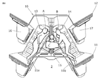
- FIG. 4 is a cross-sectional view taken along the line AA of FIG. 3 and shows a state where the partition plate is raised to a maximum position (shielded state).
- FIG. 4 is a cross-sectional view taken along the line AA in FIG. 3 and shows a state in which the partition plate is accommodated in the intermediate portion (open state). It is a figure which shows the usage example of a sheet unit.
- the heights substantially coincide means that the height difference is within 2 cm (preferably within 1 cm).
- “Front” and “rear” refer to the direction of travel of the aircraft and the direction opposite to the direction of travel, respectively.
- FIG. 1 is a top view showing an overhead view of an aircraft cabin equipped with an aircraft seat unit according to the present embodiment.
- the left side in the drawing is the front side of the aircraft, and the right side is the rear side of the aircraft.
- a plurality of aircraft seat units 10 are arranged in a row on the floor 2, and single seats 20 are arranged in a row on the windows on both sides.
- FIG. 2 is a perspective view of the aircraft seat unit 10 as viewed obliquely from above.
- FIG. 3 is a perspective view of the aircraft seat unit 10 as viewed from the front upper side.
- FIG. 4 is a top view of the aircraft seat unit 10 as viewed from directly above, showing a seat state.
- FIG. 5 is a top view of the aircraft seat unit 10 as viewed from directly above, showing a bed state.
- the aircraft seat unit 10 is disposed adjacent to each other on the front wall 11 and the rear wall 12 standing in parallel with the floor 2 and on the floor 2 between the front wall 11 and the rear wall 12.
- a second side table 17 arranged on the side of the second sheet 14.
- the front wall 11 and the rear wall 12 have a common shape. Accordingly, the rear wall 12 of the front seat unit 10 can be shared as the front wall 11 of the rear seat unit 10 adjacent thereto.
- the seat unit 10 has a front wall 11 and a rear wall 12.
- the first seat 13 and the second seat 14 and the rear wall 12 are supplied as a set of seat units from an interior manufacturer, and these are arranged in the front and rear and assembled to the aircraft 1 so that the rear wall 12 Is shared as the front wall 11.
- the front wall 11 has trapezoidal columnar protrusions 11a and 11b protruding forward on both sides thereof.
- the rear wall 12 has trapezoidal columnar protrusions 12a and 12b protruding forward on both sides thereof.
- the inside of the protrusions 12a and 12b of the rear wall 12 is hollow, and the first side table 16 is placed on the upper surface of the protrusion 12a, and the second side table 17 is placed on the upper surface of the protrusion 12b. The same applies to the front wall 11.
- the front wall 11 and the rear wall 12 have a substantially W shape when viewed from above.
- the axis X1 of the first seat 13 and the axis X2 of the second seat 14 are angled at the same angle on the opposite side with respect to the traveling direction D of the aircraft 1.
- the dimensions along the traveling direction D of the first sheet 13 and the second sheet 14 in the bed state (FIG. 5) can be suppressed, and a large number of seat units can be mounted on the aircraft 1.
- a substantially triangular prism-shaped space is generated between the first sheet 13 and the second sheet 14.
- An intermediate portion 15 is provided by using this space to make effective use of the space.
- the intermediate portion 15 is disposed in a three substantially prismatic space between the front wall 11, the first sheet 13, and the second sheet 14.
- seat 14 is common, you may make both differ.
- seat 14 can also be used as the sheet
- the first seat 13 has a first seat 13a and a first backrest 13b.
- the first backrest 13b is pivotally connected to the rear end of the first seat 13a.
- the reclining mechanism 13c (see FIG. 6 described later) is driven and controlled, and at the same time the first backrest 13b falls backward with respect to the first seat 13a, the first seat 13a Slides horizontally forward, and the upper surfaces of the first seat 13a and the first backrest 13b become flat horizontally.
- This is called a bed state (see FIG. 5).
- a part of the first seat 13a enters the inside of the protruding portion 11a. That is, the inside of the protruding portion 11a becomes a part of the use space of the user, and the user can lie on the first sheet 13 with his legs extended.
- the first back 13b rises with respect to the first seat 13a, and at the same time, the first seat 13a slides backward, and the first seat 13a In contrast, the first backrest 13b is angled. This is called a sheet state (see FIGS. 3 and 4).
- the reclining mechanism 13c may slightly lift the front end of the first seat 13a. As a result, the user can sit on the first seat 13a in an easy posture.
- the second seat 14 has a second seat 14a and a second backrest 14b.
- the second backrest 14b is pivotally connected to the rear end of the second seat 14a.
- the reclining mechanism 14c (see FIG. 6 described later) is driven and controlled, and the second backrest 14b falls backward with respect to the second seat 14a, and at the same time, the second seat 14a.
- a part of the second seat 14a enters the inside of the protruding portion 11b. That is, the inside of the protruding portion 11b becomes a part of the use space of the user, and the user can lie on the second sheet 14 with his legs extended.
- the second backrest 14b rises with respect to the second seat 14a, and at the same time, the second seat 14a slides backward, and the second seat 14a In contrast, the second backrest 14b is angled. This is called a sheet state (see FIGS. 3 and 4).
- the reclining mechanism 14c may slightly lift the front end of the second seat 14a. As a result, the user can sit on the second seat 14a in an easy posture.
- the reclining mechanisms 13c and 14c for example, the technology disclosed in JP-T-2010-520117 can be used.
- the intermediate portion 15 is disposed between a pedestal 15a having a triangular prism shape disposed on the first sheet 13 side, a pedestal 15b having a triangular prism shape disposed on the second sheet 14 side, and the pedestals 15a and 15b. It has the support part 15c which is a rectangular parallelepiped shape, and the partition plate 15d supported by the support part 15c.
- the support portion 15 c and the partition plate 15 d extend from the back surface of the front wall 11 to the front surface of the rear wall 12.
- the end portion of the partition plate 15d is engaged with the vertical groove 11c on the back surface of the front wall 11 and the vertical groove 12c on the back surface of the rear wall 12, and can be moved up and down by being guided by these. ing.
- FIG. 6 and 7 are AA cross-sectional views of FIG.
- pedestals 15a and 15b are fixed to the floor, and the upper surface thereof is stretched with a cushioning material like the seat.
- the support part 15c is arrange
- Each of the bases 15a and 15b can be composed of a plurality of members.
- the support portion 15c on which a cushioning material is stretched has a slit 15f that opens at the center of the upper surface.
- a partition plate 15d is slidably disposed in the slit 15f.
- the partition plate 15d is preferably made of, for example, a translucent or opaque resin.
- the partition plate 15d in the shielded state is the line of sight of the user seated on the first seat 13a or the second seat 14a in the seat state (usually 10 cm or more below the upper end of the first backrest 13b or the second backrest 14b). It becomes higher. Thereby, the private space of the user sitting on the 1st sheet
- a user or an occupant manually or electrically slides the support portion 15c downward with respect to the bases 15a and 15b, and slides the partition plate 15d downward with respect to the support portion 15c to be accommodated therein. be able to.
- Such a state is called an open state.
- the open state as shown in FIG. 7, the height positions of the upper surfaces of the bases 15a and 15b and the upper surface of the support portion 15c substantially coincide. Further, the height of the upper surface of the support portion 15c and the height of the upper end of the partition plate 15d are substantially the same. That is, as shown in FIG. 7, the entire upper surface of the intermediate portion 15 has a uniform height.
- the height of the first backrest 13 b and the second backrest 14 b is the height of the upper surface of the intermediate portion 15. Approximate with height.
- FIG. 8 shows an example of use of the space obtained in the seat unit 10 in this way.
- the user A lies on the first sheet 13 in the bed state
- the user B lies on the second sheet 14 in the bed state
- the infant C lies on the intermediate portion 15 with the partition plate 15d and the support portion 15c lowered.
- foot can be accommodated in protrusion part 11a, 11b of the front wall 11 as shown with a dotted line, a user can extend a leg
- the seat unit for an aircraft it is not necessary to secure an adult seat for the infant C, and the economic burden on the users A and B accompanying the infant C can be reduced.
- the upper end of the partition plate 15d in the shielded state can be lifted high while keeping the intermediate portion 15 low. That is, assuming that there is no support portion 15c, the height of the upper surface of the intermediate portion 15 (the height of the upper end of the partition plate 15d) is substantially equal to the height of the upper surface of the first backrest 13b or the second backrest 14b in the bed state. In this case, the height of the partition plate 15d is only twice as high as that of the intermediate portion 15 in the shielded state. In such a case, the height of the partition plate 15d in the shielded state is below the line of sight of the user sitting on the seat, so that a private space cannot be secured on the first seat 13 side and the second seat 14 side.
- a two-step lifting structure in which the support portion 15c is provided in the intermediate portion 15, the support portion 15c is slid with respect to the bases 15a and 15b, and the partition plate 15d is slid with respect to the support portion 15c.
- the upper end of the partition plate 15 d can be raised to a height position that is approximately three times the height of the intermediate portion 15.
- it can also be set as the 3 steps
- the intermediate section 15 can be used not only for infants but also for the purpose of placing important musical instruments within reach of, for example, performers when boarding.
- the intermediate portion 15 can be used to place a shogi board, a chess board, or the like when a passenger of the first seat 13 and a passenger of the second seat 14 want to play a shogi or chess battle.
- the upper end of the partition plate 15 d in the shielding state may be below the upper surface of the intermediate portion 15.
Landscapes
- Engineering & Computer Science (AREA)
- Aviation & Aerospace Engineering (AREA)
- Seats For Vehicles (AREA)
- Special Chairs (AREA)
Abstract
航空機用のシートユニットは、第1シート13と第2シート14との間に配置された中間部15を有し、中間部15は、ベッド状態において、第1背もたれ13bと第2背もたれ13bとに対し、上面の高さが略一致した状態で隣接し、中間部15は、昇降可能な仕切り板15dを有し、仕切り板15dが中間部15に収容された状態で、仕切り板15dの上端は中間部15の上面の高さ以下に位置し、また仕切り板15dを上昇させたとき、仕切り板15dの上端は、少なくともシート状態における第1座席13a又は第2座席13bに着座した利用者の目線より上方へと移動可能である。
Description
本発明は、航空機用のシートユニットに関する。
航空機に設けられるシートにおいて、背もたれが起立して着席した状態と、当該背もたれ等がリクライニングして水平状態となりベッドとして使用できる状態と、を選択的に変更できるシート構造体が、例えばファーストクラスやビジネスクラス向けのシートとして知られている。
一方、特許文献1に示すように、進行方向に並べたシートの間の仕切り板を上下可能とする航空機用シート構造体も知られている。かかる構成によれば、例えば各シートに他人が座る場合には、仕切り板を上げることで、シート毎にプライベートな空間を確保することができる。一方、家族など二人連れの乗客が隣り合って座る場合には、仕切り板を下げることによって二人が共有できる一つの空間を確保することができ、これにより乗客に応じた使い分けが可能となっている。
ところで、近年、航空機を利用する乗客の多様化が進み、例えば乳児連れの家族が搭乗するケースも増えている。かかる場合、例えばビジネスシートを利用する際には、乳児でも大人ひとり分の料金、またはそれに近い額の料金を請求されることもあり、乗客の経済的負担は過大である。一方、乳児の体形及び体重は大人の数分の一であることから、乳児の体形に合わせた小型の専用シートを導入するとともに、低額の料金設定を求める声もある。しかしながら、乳児連れの家族が常に搭乗するとは限らないので、乳児専用のシートを航空機に導入することは、座席占有率の低下を招く虞れがある。
そこで、本発明の目的は、乗客の多様化に対応するとともに、客室内のスペースを有効活用できる航空機用のシートユニットを提供することにある。
上記の目的を達成するために、本発明による航空機用のシートユニットは、
第1座席に対して第1背もたれが枢動可能となっており、乗客が着席可能なシート状態と、前記第1座席と前記第1背もたれとがフラットになるベッド状態との形態変更が可能な第1シートと、
前記第1シートに隣接して配置され、第2座席に対して第2背もたれが枢動可能となっており、乗客が着席可能なシート状態と、前記第1座席と前記第1背もたれとがフラットになるベッド状態との形態変更が可能な第2シートと、
前記第1シートと前記第2シートとの間に配置された中間部と、を有し、
前記中間部は、前記ベッド状態において、前記第1背もたれと前記第2背もたれとに対し、上面の高さが略一致した状態で隣接し、
前記中間部は、昇降可能な仕切り板を有し、
前記仕切り板が前記中間部に収容された状態で、前記仕切り板の上端は前記中間部の上面の高さに略一致するか、それ以下に位置し、また前記仕切り板を上昇させたとき、前記仕切り板の上端は、少なくとも前記シート状態における前記第1背もたれ又は前記第2背もたれより上方へと移動可能である、
ことを特徴とする。
本発明によれば、乗客の多様化に対応するとともに、客室内のスペースを有効活用できる航空機用のシートユニットを提供することができる。
以下、図面を参照して本発明の実施の形態を説明する。なお、本明細書中、「高さが略一致する」とは、高さの差が2cm以内(好ましくは1cm以内)であることをいう。また「前方」、及び「後方」とは、それぞれ航空機の進行方向、及び進行方向とは逆方向をいうものとする。
図1は、本実施形態にかかる航空機用のシートユニットを搭載した航空機の客室を俯瞰して示す上面図である。図1において、図示上左側が航空機の先頭側であり、右側が航空機の後部側である。航空機1は、床2上に複数の航空機用のシートユニット10を中央に一列に配列しており、また両側の窓側には、単座のシート20を一列にそれぞれ配列している。
図2は、航空機用のシートユニット10を斜め上方から見た斜視図である。図3は、航空機用のシートユニット10を前方上方から見た斜視図である。図4は、航空機用のシートユニット10を真上から見た上面図であり、シート状態を示す。図5は、航空機用のシートユニット10を真上から見た上面図であり、ベッド状態を示す。
図2,3において、航空機用のシートユニット10は、床2から平行に立設した前方壁11及び後方壁12と、前方壁11と後方壁12との間の床2に互いに隣接して配置された第1シート13及び第2シート14と、第1シート13と第2シート14との間に配置された中間部15と、第1シート13の脇に配置された第1サイドテーブル16と、第2シート14の脇に配置された第2サイドテーブル17と、を有する。
前方壁11と後方壁12とは共通の形状を有する。これにより、前方側のシートユニット10の後方壁12を、これに隣接する後方側のシートユニット10の前方壁11として共用することができる。ここでは説明の都合上、シートユニット10が、前方壁11と後方壁12とを有するものとしている。しかしながら実際には、第1シート13及び第2シート14と、後方壁12とをシートユニットの1セットとして内装メーカーより供給し、これらを前後に配列して航空機1に組み付けることで、後方壁12を前方壁11として共用することとなる。
前方壁11は、その両側に前方に向かって突き出した台形柱状の突出部11a、11bを有する。同様に、後方壁12は、その両側に前方に向かって突き出した台形柱状の突出部12a、12bを有する。後方壁12の突出部12a、12bの内部は空洞となっており、突出部12aの上面に第1サイドテーブル16が置かれ、突出部12bの上面に第2サイドテーブル17が置かれている。前方壁11についても同様である。
図4に示すように、前方壁11及び後方壁12は、上方から見て略W形状を有している。また、第1シート13の軸線X1と第2シート14の軸線X2とは、航空機1の進行方向Dに対して逆側に同角度で角度付されている。これによりベッド状態(図5)にした場合における第1シート13及び第2シート14の進行方向Dに沿った寸法を抑えることができ、多数のシートユニットを航空機1に搭載できる。一方、第1シート13及び第2シート14をこのような配置とすることで、第1シート13と第2シート14の間に略三角柱状の空間が生じる。この空間を利用して中間部15を設け、スペースの有効活用を図っている。
中間部15は、前方壁11と第1シート13と前記第2シート14に接するようにして、その間の三略角柱状の空間に配置される。第1シート13と第2シート14の構造は共通しているが、両者を異ならせてもよい。なお、第1シート13又は第2シート14を、窓側のシート20として用いることもできる。
第1シート13は、第1座席13aと、第1背もたれ13bとを有する。第1背もたれ13bは、第1座席13aの後端に枢動可能に連結されている。利用者が不図示のスイッチを操作することにより、リクライニング機構13c(後述する図6参照)が駆動制御され、第1背もたれ13bが第1座席13aに対して後方に倒れると同時に、第1座席13aが前方に水平にスライドして、第1座席13aと第1背もたれ13bの上面が水平にフラットになる。これをベッド状態という(図5参照)。ベッド状態になると、第1座席13aの一部が突出部11aの内部に進入する。つまり、突出部11aの内部は利用者の使用空間の一部となり、利用者は足を延ばして第1シート13上に横たわることができる。
このベッド状態から、利用者が不図示のスイッチを逆操作することにより、第1背もたれ13bが第1座席13aに対して立ち上がると同時に、第1座席13aが後方にスライドして、第1座席13aに対し第1背もたれ13bが角度付けされる。これをシート状態という(図3、4参照)。シート状態では、リクライニング機構13cが第1座席13aの前方端を少し持ち上げるようにしてもよい。これにより利用者は楽な姿勢で第1座席13aに着座することができる。
同様に、第2シート14は、第2座席14aと、第2背もたれ14bとを有する。第2背もたれ14bは、第2座席14aの後端に枢動可能に連結されている。利用者が不図示のスイッチを操作することにより、リクライニング機構14c(後述する図6参照)が駆動制御され、第2背もたれ14bが第2座席14aに対して後方に倒れると同時に、第2座席14aが前方に水平にスライドして、第2座席14aと第2背もたれ14bの上面が水平にフラットになる。これをベッド状態という(図5参照)。ベッド状態になると、第2座席14aの一部が突出部11bの内部に進入する。つまり、突出部11bの内部は利用者の使用空間の一部となり、利用者は足を延ばして第2シート14上に横たわることができる。
このベッド状態から、利用者が不図示のスイッチを逆操作することにより、第2背もたれ14bが第2座席14aに対して立ち上がると同時に、第2座席14aが後方にスライドして、第2座席14aに対し第2背もたれ14bが角度付けされる。これをシート状態という(図3,4参照)。シート状態では、リクライニング機構14cが第2座席14aの前方端を少し持ち上げるようにしてもよい。これにより利用者は楽な姿勢で第2座席14aに着座することができる。なお、リクライニング機構13c、14cについては、例えば特表2010-520117号の技術を用いることができる。
図5において、中間部15は、第1シート13側に配置した三角柱状である台座15aと、第2シート14側に配置した三角柱状である台座15bと、台座15a、15bの間に配置された直方体状である支持部15cと、支持部15cに支持された仕切り板15dとを有する。支持部15c及び仕切り板15dは、前方壁11の背面から後方壁12の前面まで延在している。仕切り板15dの端部は、図5に示すように、前方壁11の背面の垂直溝11c及び後方壁12の背面の垂直溝12cに係合しており、これらに案内されて昇降可能となっている。
図6,7は、図3のA-A断面図である。図において、台座15a、15bは床に固定されており、その上面は座席と同様にクッション性を有する素材が張られている。台座15a、15bの間のガイド15e上に、支持部15cが上下方向にスライド可能に配置されている。台座15a、15bは、それぞれ複数の部材からなることができる。
台座15a、15bと同様にクッション性を有する素材が張られた支持部15cは、上面中央に開口するスリット15fを有している。スリット15f内には、仕切り板15dが上下方向にスライド可能に配置されている。仕切り板15dは、例えば半透明もしくは不透明な樹脂製であると好ましい。
たとえば第1シート13と第2シート14とに座る利用者が見ず知らずの他人である場合、第1シート13及び第2シート14ごとに、それぞれプライベートな空間を画成するのが望ましい。かかる場合、利用者又は乗員が手動又は電動により、台座15a、15bに対して支持部15cを上方へとスライドし、また支持部15cに対して仕切り板15dを上方へとスライドする。かかる状態を遮蔽状態といい、図2及び図6に示している。遮蔽状態で仕切り板15dの上端は、シート状態にある第1座席13a又は第2座席14aに着座した利用者の目線(通常、第1背もたれ13b又は第2背もたれ14bの上端より10cm以上、下方になる)より上方になる。これにより、第1シート13又は第2シート14に座る利用者のプライベート空間が確保される。
一方、利用者又は乗員が手動又は電動により、台座15a、15bに対して支持部15cを下方へとスライドし、また支持部15cに対して仕切り板15dを下方へとスライドして内部に収容することができる。かかる状態を開放状態という。開放状態では、図7に示すように、台座15a、15bの上面と、支持部15cの上面の高さ位置が略一致する。また、支持部15cの上面と、仕切り板15dの上端の高さが略一致する。つまり、図7に示すように、中間部15の上面全体が均一な高さとなる。
かかる状態を維持しつつ、図5に示すように、第1シート13と第2シート14とをベッド状態とすると、第1背もたれ13bと第2背もたれ14bの高さが、中間部15の上面の高さと略一致する。
すると、前方壁11と後方壁12との間に、第1シート13と第2シート14と中間部15とにより形成される上面がフラットな広々した空間が形成されることとなる。
図8に、このようにしてシートユニット10内に得られた空間の使用例を示す。ベッド状態にした第1シート13に利用者Aが横たわり、ベッド状態にした第2シート14に利用者Bが横たわり、仕切り板15dと支持部15cを下げた中間部15上に乳児Cが横たわった状態を示している。中間部15は、支持部15c及び仕切り板15dを開放状態まで下げることでフラットになるから、乳児Cが横たわる際に邪魔にならない。また、点線で示すように、前方壁11の突出部11a、11b内に、利用者A,Bの足を収容できるので、利用者は足を延ばして楽な体勢を取ることができる。
本実施の形態にかかる航空機用のシートユニットによれば、乳児Cのために大人用のシートを確保する必要がなくなり、乳児Cを連れた利用者A,Bの経済的負担を軽減できる。
一方、見知らぬ他人である者同士が、それぞれ第1シート13と第2シート14とに着座する際には、図2、6に示すように、支持部15c及び仕切り板15dを遮蔽状態まで持ち上げることで、それぞれのプライベート空間を確保できる。つまり、利用者が乳児連れであるか否かに関わらず、シートユニット10を共通して活用できるから、航空機の座席占有率を向上できる。
更に本実施の形態によれば、支持部15cを設けることで、中間部15を低く留めたまま、遮蔽状態での仕切り板15dの上端を高く持ち上げることができる。すなわち、仮に支持部15cがないとすると、中間部15の上面の高さ(仕切り板15dの上端の高さ)を、ベッド状態での第1背もたれ13b又は第2背もたれ14bの上面高さと略一致させた場合、遮蔽状態では仕切り板15dの高さは、最大でも中間部15の2倍の高さにしかならない。かかる場合、遮蔽状態での仕切り板15dの高さは、座席に座る利用者の目線を下回ってしまうから、第1シート13側と第2シート14側とでプライベート空間を確保できないこととなる。
そこで本実施の形態では、中間部15に支持部15cを設けた2段昇降構造とし、台座15a、15bに対して支持部15cをスライドさせ、且つ支持部15cに対して仕切り板15dをスライドさせるようにしている。これにより、理論上、中間部15の高さの約3倍の高さ位置まで、仕切り板15dの上端を上昇させることができる。なお、複数の支持部を設けることで、3段昇降構造以上とすることもできる。
更に中間部15は、乳児以外にも、例えば演奏家等が搭乗する際に大事な楽器を目の届くところにおきたいという目的にも使用できる。あるいは、第1シート13の乗客と第2シート14の乗客とが、将棋やチェスの対戦を行いたい場合など、将棋盤やチェス盤などを置くために中間部15を利用することもできる。
その他、本発明の要旨を逸脱しない範囲で上記実施例に種々の改変を施すことも可能である。例えば遮蔽状態での仕切り板15dの上端は、中間部15の上面以下にあればよい。
1:航空機、2:床、11:前方壁、12:後方壁、13:第1シート、14:第2シート、15:中間部、15c:支持部、15d:仕切り板、16:第1サイドテーブル、17:第2サイドテーブル
Claims (4)
- 第1座席に対して第1背もたれが枢動可能となっており、乗客が着席可能なシート状態と、前記第1座席と前記第1背もたれとがフラットになるベッド状態との形態変更が可能な第1シートと、
前記第1シートに隣接して配置され、第2座席に対して第2背もたれが枢動可能となっており、乗客が着席可能なシート状態と、前記第1座席と前記第1背もたれとがフラットになるベッド状態との形態変更が可能な第2シートと、
前記第1シートと前記第2シートとの間に配置された中間部と、を有し、
前記中間部は、前記ベッド状態において、前記第1背もたれと前記第2背もたれとに対し、上面の高さが略一致した状態で隣接し、
前記中間部は、昇降可能な仕切り板を有し、
前記仕切り板が前記中間部に収容された状態で、前記仕切り板の上端は前記中間部の上面に略一致するか、それ以下に位置し、また前記仕切り板を上昇させたとき、前記仕切り板の上端は、少なくとも前記シート状態における前記第1座席又は前記第2座席に着座した利用者の目線より上方へと移動可能である、
ことを特徴とする航空機用のシートユニット。 - 前記中間部は、前記中間部から上方へ移動可能な支持部材を有し、前記仕切り板は、前記支持部材から上方へと移動可能である、
ことを特徴とする請求項1に記載の航空機用のシートユニット。 - 前記第1シートの軸線と前記第2シートの軸線とは、進行方向に対して逆側に角度付されており、前記中間部は前記第1シートと前記第2シートの間の三角柱状の空間に配置されている、
ことを特徴とする請求項1又は2に記載の航空機用のシートユニット。 - 前記シート状態から前記ベッド状態へ形態変更が行われるとき、前記第1背もたれが前記第1座席に対して枢動しつつ、前記第1座席が前記第1背もたれと反対側へスライドし、また前記第2背もたれが前記第2座席に対して枢動しつつ、前記第2座席が前記第2背もたれと反対側へスライドする、
ことを特徴とする請求項1~3のいずれかに記載の航空機用のシートユニット。
Priority Applications (4)
| Application Number | Priority Date | Filing Date | Title |
|---|---|---|---|
| EP18912749.1A EP3778398A4 (en) | 2018-03-27 | 2018-03-27 | AIRCRAFT SEAT UNIT |
| JP2020510232A JP6975318B2 (ja) | 2018-03-27 | 2018-03-27 | 航空機用のシートユニット |
| PCT/JP2018/012405 WO2019186689A1 (ja) | 2018-03-27 | 2018-03-27 | 航空機用のシートユニット |
| US16/981,523 US20210009271A1 (en) | 2018-03-27 | 2018-03-27 | Seat unit for aircraft |
Applications Claiming Priority (1)
| Application Number | Priority Date | Filing Date | Title |
|---|---|---|---|
| PCT/JP2018/012405 WO2019186689A1 (ja) | 2018-03-27 | 2018-03-27 | 航空機用のシートユニット |
Publications (1)
| Publication Number | Publication Date |
|---|---|
| WO2019186689A1 true WO2019186689A1 (ja) | 2019-10-03 |
Family
ID=68062595
Family Applications (1)
| Application Number | Title | Priority Date | Filing Date |
|---|---|---|---|
| PCT/JP2018/012405 WO2019186689A1 (ja) | 2018-03-27 | 2018-03-27 | 航空機用のシートユニット |
Country Status (4)
| Country | Link |
|---|---|
| US (1) | US20210009271A1 (ja) |
| EP (1) | EP3778398A4 (ja) |
| JP (1) | JP6975318B2 (ja) |
| WO (1) | WO2019186689A1 (ja) |
Families Citing this family (1)
| Publication number | Priority date | Publication date | Assignee | Title |
|---|---|---|---|---|
| EP3768597A1 (en) * | 2018-03-23 | 2021-01-27 | Adient Aerospace, LLC | Seat unit and passenger seating arrangement provided within a vehicle cabin |
Citations (7)
| Publication number | Priority date | Publication date | Assignee | Title |
|---|---|---|---|---|
| JP2010501447A (ja) * | 2006-10-12 | 2010-01-21 | ビー イー エアロスペイス,インク. | 移動および回転可能な乗客シート |
| JP2010520117A (ja) | 2007-03-08 | 2010-06-10 | プレミアム エアクラフト インテリアーズ ユーケー リミテッド | 航空機座席 |
| JP2011506165A (ja) * | 2007-12-06 | 2011-03-03 | ビー イー エアロスペイス,インク. | 航空機のシート配置構造及びシート |
| JP2012521328A (ja) * | 2009-03-23 | 2012-09-13 | エア ニュージーランド リミティド | 輸送手段の乗客用座席配置の改良 |
| JP2015511557A (ja) * | 2012-03-14 | 2015-04-20 | ビーイー・エアロスペース・インコーポレーテッド | 組み合わせベッドを備える航空機の乗客用スイート |
| WO2017168746A1 (ja) | 2016-04-01 | 2017-10-05 | 株式会社ジャムコ | 航空機用シート構造体 |
| WO2018051496A1 (ja) * | 2016-09-16 | 2018-03-22 | 株式会社ジャムコ | 航空機用シートユニット及び複数シート構造 |
Family Cites Families (8)
| Publication number | Priority date | Publication date | Assignee | Title |
|---|---|---|---|---|
| KR20000075486A (ko) * | 1997-02-20 | 2000-12-15 | 사무엘 매튜 | 비행기 좌석 |
| US7578470B2 (en) * | 2006-04-21 | 2009-08-25 | Be Aerospace, Inc. | Passenger seating arrangement |
| GB0903744D0 (en) * | 2009-03-04 | 2009-04-15 | Virgin Atlantic Airways Ltd | A seating insallation for a passenger vehicle |
| FR2953168B1 (fr) * | 2009-12-02 | 2012-01-06 | Eads Sogerma | Siege convertible en couchette |
| FR3003540B1 (fr) * | 2013-03-25 | 2015-05-29 | Eads Sogerma | Agencement de sieges convertibles en couchettes |
| FR3055128A1 (fr) * | 2016-08-17 | 2018-02-23 | Zodiac Seats France | Agencement de sieges permettant d'augmenter l'intimite des passagers, notamment d'un avion |
| FR3059951B1 (fr) * | 2016-12-14 | 2019-05-17 | Zodiac Seats France | Arrangement de sieges individuels pour passagers d'un avion |
| CN111164013B (zh) * | 2017-10-03 | 2023-10-31 | 新加坡航空公司 | 飞机座椅 |
-
2018
- 2018-03-27 JP JP2020510232A patent/JP6975318B2/ja active Active
- 2018-03-27 WO PCT/JP2018/012405 patent/WO2019186689A1/ja unknown
- 2018-03-27 EP EP18912749.1A patent/EP3778398A4/en active Pending
- 2018-03-27 US US16/981,523 patent/US20210009271A1/en not_active Abandoned
Patent Citations (7)
| Publication number | Priority date | Publication date | Assignee | Title |
|---|---|---|---|---|
| JP2010501447A (ja) * | 2006-10-12 | 2010-01-21 | ビー イー エアロスペイス,インク. | 移動および回転可能な乗客シート |
| JP2010520117A (ja) | 2007-03-08 | 2010-06-10 | プレミアム エアクラフト インテリアーズ ユーケー リミテッド | 航空機座席 |
| JP2011506165A (ja) * | 2007-12-06 | 2011-03-03 | ビー イー エアロスペイス,インク. | 航空機のシート配置構造及びシート |
| JP2012521328A (ja) * | 2009-03-23 | 2012-09-13 | エア ニュージーランド リミティド | 輸送手段の乗客用座席配置の改良 |
| JP2015511557A (ja) * | 2012-03-14 | 2015-04-20 | ビーイー・エアロスペース・インコーポレーテッド | 組み合わせベッドを備える航空機の乗客用スイート |
| WO2017168746A1 (ja) | 2016-04-01 | 2017-10-05 | 株式会社ジャムコ | 航空機用シート構造体 |
| WO2018051496A1 (ja) * | 2016-09-16 | 2018-03-22 | 株式会社ジャムコ | 航空機用シートユニット及び複数シート構造 |
Non-Patent Citations (1)
| Title |
|---|
| See also references of EP3778398A4 |
Also Published As
| Publication number | Publication date |
|---|---|
| EP3778398A1 (en) | 2021-02-17 |
| JPWO2019186689A1 (ja) | 2021-01-07 |
| EP3778398A4 (en) | 2021-10-20 |
| JP6975318B2 (ja) | 2021-12-01 |
| US20210009271A1 (en) | 2021-01-14 |
Similar Documents
| Publication | Publication Date | Title |
|---|---|---|
| US11787545B2 (en) | Platform first class | |
| EP3774484B1 (en) | Vehicular seating suite configuration | |
| US5954401A (en) | Reclining seat and ottoman system for aircraft including amenity cabinet | |
| US9126689B2 (en) | Vehicle passenger seating | |
| CN109018371B (zh) | 用于交通工具客舱的座椅单元 | |
| US8342450B2 (en) | Seating arrangement of a vehicle compartment | |
| US20160031561A1 (en) | Seating Arrangement, Seat Unit, Tray Table and Seating System | |
| US9327837B2 (en) | Modular airplane seat unit | |
| US20150210395A1 (en) | Armrest and seat arrangement comprising the same | |
| JP2008074398A (ja) | シートユニット | |
| US20120112500A1 (en) | Vehicle Seating Apparatus | |
| US20150210396A1 (en) | Seat arrangement, aircraft cabin as well as armrest and seat or seat group for use therein | |
| JP7026224B2 (ja) | 航空機用のシートユニット | |
| WO2011077366A1 (en) | Improvements relating to passenger vehicle seating | |
| WO2019186689A1 (ja) | 航空機用のシートユニット | |
| EP4003838A1 (en) | Aircraft passenger seat unit with movable panel | |
| US2649593A (en) | Child's travel unit | |
| CN108974034B (zh) | 一种商务座椅及列车车厢 | |
| KR101905096B1 (ko) | 등받이와 식탁 및 고정수단이 구비된 분할형 의자 | |
| KR20230000372A (ko) | 캠핑용 목적 기반 차량 | |
| JP2022044498A (ja) | ソファ | |
| WO2011141890A1 (en) | Arrangement for passenger |
Legal Events
| Date | Code | Title | Description |
|---|---|---|---|
| 121 | Ep: the epo has been informed by wipo that ep was designated in this application |
Ref document number: 18912749 Country of ref document: EP Kind code of ref document: A1 |
|
| ENP | Entry into the national phase |
Ref document number: 2020510232 Country of ref document: JP Kind code of ref document: A |
|
| NENP | Non-entry into the national phase |
Ref country code: DE |
|
| ENP | Entry into the national phase |
Ref document number: 2018912749 Country of ref document: EP Effective date: 20201027 |