WO2019181150A1 - アイウェア - Google Patents
アイウェア Download PDFInfo
- Publication number
- WO2019181150A1 WO2019181150A1 PCT/JP2019/000691 JP2019000691W WO2019181150A1 WO 2019181150 A1 WO2019181150 A1 WO 2019181150A1 JP 2019000691 W JP2019000691 W JP 2019000691W WO 2019181150 A1 WO2019181150 A1 WO 2019181150A1
- Authority
- WO
- WIPO (PCT)
- Prior art keywords
- temple
- frame
- eyewear
- eyewear according
- control unit
- Prior art date
Links
- 229910052751 metal Inorganic materials 0.000 claims description 26
- 239000002184 metal Substances 0.000 claims description 26
- 230000005489 elastic deformation Effects 0.000 claims description 5
- 238000012545 processing Methods 0.000 claims description 3
- 239000011521 glass Substances 0.000 description 34
- 239000000463 material Substances 0.000 description 27
- 239000004973 liquid crystal related substance Substances 0.000 description 17
- 239000011347 resin Substances 0.000 description 14
- 229920005989 resin Polymers 0.000 description 14
- 238000005452 bending Methods 0.000 description 8
- 238000004891 communication Methods 0.000 description 5
- 230000037303 wrinkles Effects 0.000 description 5
- 230000000694 effects Effects 0.000 description 3
- 230000001133 acceleration Effects 0.000 description 2
- 238000012937 correction Methods 0.000 description 2
- 238000013461 design Methods 0.000 description 2
- 238000010586 diagram Methods 0.000 description 2
- 230000004438 eyesight Effects 0.000 description 2
- 230000006870 function Effects 0.000 description 2
- 238000004519 manufacturing process Methods 0.000 description 2
- 238000000034 method Methods 0.000 description 2
- 238000012986 modification Methods 0.000 description 2
- 230000004048 modification Effects 0.000 description 2
- -1 nickel metal hydride Chemical class 0.000 description 2
- QTBSBXVTEAMEQO-UHFFFAOYSA-M Acetate Chemical compound CC([O-])=O QTBSBXVTEAMEQO-UHFFFAOYSA-M 0.000 description 1
- OKTJSMMVPCPJKN-UHFFFAOYSA-N Carbon Chemical compound [C] OKTJSMMVPCPJKN-UHFFFAOYSA-N 0.000 description 1
- 229920002160 Celluloid Polymers 0.000 description 1
- RYGMFSIKBFXOCR-UHFFFAOYSA-N Copper Chemical compound [Cu] RYGMFSIKBFXOCR-UHFFFAOYSA-N 0.000 description 1
- JOYRKODLDBILNP-UHFFFAOYSA-N Ethyl urethane Chemical compound CCOC(N)=O JOYRKODLDBILNP-UHFFFAOYSA-N 0.000 description 1
- HBBGRARXTFLTSG-UHFFFAOYSA-N Lithium ion Chemical compound [Li+] HBBGRARXTFLTSG-UHFFFAOYSA-N 0.000 description 1
- 239000004952 Polyamide Substances 0.000 description 1
- 239000004697 Polyetherimide Substances 0.000 description 1
- BQCADISMDOOEFD-UHFFFAOYSA-N Silver Chemical compound [Ag] BQCADISMDOOEFD-UHFFFAOYSA-N 0.000 description 1
- 230000002411 adverse Effects 0.000 description 1
- 229910045601 alloy Inorganic materials 0.000 description 1
- 239000000956 alloy Substances 0.000 description 1
- 229910052782 aluminium Inorganic materials 0.000 description 1
- XAGFODPZIPBFFR-UHFFFAOYSA-N aluminium Chemical compound [Al] XAGFODPZIPBFFR-UHFFFAOYSA-N 0.000 description 1
- 230000003190 augmentative effect Effects 0.000 description 1
- 230000005540 biological transmission Effects 0.000 description 1
- 210000000988 bone and bone Anatomy 0.000 description 1
- 229910052799 carbon Inorganic materials 0.000 description 1
- 239000004020 conductor Substances 0.000 description 1
- 229910052802 copper Inorganic materials 0.000 description 1
- 239000010949 copper Substances 0.000 description 1
- 238000001514 detection method Methods 0.000 description 1
- PCHJSUWPFVWCPO-UHFFFAOYSA-N gold Chemical compound [Au] PCHJSUWPFVWCPO-UHFFFAOYSA-N 0.000 description 1
- 229910052737 gold Inorganic materials 0.000 description 1
- 239000010931 gold Substances 0.000 description 1
- 229910001416 lithium ion Inorganic materials 0.000 description 1
- 229910052987 metal hydride Inorganic materials 0.000 description 1
- 150000002739 metals Chemical class 0.000 description 1
- 238000000465 moulding Methods 0.000 description 1
- 230000003183 myoelectrical effect Effects 0.000 description 1
- 229910052759 nickel Inorganic materials 0.000 description 1
- PXHVJJICTQNCMI-UHFFFAOYSA-N nickel Substances [Ni] PXHVJJICTQNCMI-UHFFFAOYSA-N 0.000 description 1
- 230000003287 optical effect Effects 0.000 description 1
- 230000002093 peripheral effect Effects 0.000 description 1
- 230000000704 physical effect Effects 0.000 description 1
- 230000010287 polarization Effects 0.000 description 1
- 229920002647 polyamide Polymers 0.000 description 1
- 229920001601 polyetherimide Polymers 0.000 description 1
- 238000007665 sagging Methods 0.000 description 1
- 229910052709 silver Inorganic materials 0.000 description 1
- 239000004332 silver Substances 0.000 description 1
- 239000004984 smart glass Substances 0.000 description 1
Images


Classifications
-
- G—PHYSICS
- G02—OPTICS
- G02C—SPECTACLES; SUNGLASSES OR GOGGLES INSOFAR AS THEY HAVE THE SAME FEATURES AS SPECTACLES; CONTACT LENSES
- G02C5/00—Constructions of non-optical parts
- G02C5/14—Side-members
- G02C5/143—Side-members having special ear pieces
-
- G—PHYSICS
- G02—OPTICS
- G02C—SPECTACLES; SUNGLASSES OR GOGGLES INSOFAR AS THEY HAVE THE SAME FEATURES AS SPECTACLES; CONTACT LENSES
- G02C5/00—Constructions of non-optical parts
- G02C5/02—Bridges; Browbars; Intermediate bars
- G02C5/06—Bridges; Browbars; Intermediate bars with resilient means
-
- G—PHYSICS
- G02—OPTICS
- G02C—SPECTACLES; SUNGLASSES OR GOGGLES INSOFAR AS THEY HAVE THE SAME FEATURES AS SPECTACLES; CONTACT LENSES
- G02C5/00—Constructions of non-optical parts
- G02C5/14—Side-members
- G02C5/16—Side-members resilient or with resilient parts
-
- G—PHYSICS
- G02—OPTICS
- G02C—SPECTACLES; SUNGLASSES OR GOGGLES INSOFAR AS THEY HAVE THE SAME FEATURES AS SPECTACLES; CONTACT LENSES
- G02C5/00—Constructions of non-optical parts
- G02C5/14—Side-members
- G02C5/20—Side-members adjustable, e.g. telescopic
-
- G—PHYSICS
- G02—OPTICS
- G02C—SPECTACLES; SUNGLASSES OR GOGGLES INSOFAR AS THEY HAVE THE SAME FEATURES AS SPECTACLES; CONTACT LENSES
- G02C7/00—Optical parts
- G02C7/02—Lenses; Lens systems ; Methods of designing lenses
- G02C7/08—Auxiliary lenses; Arrangements for varying focal length
- G02C7/081—Ophthalmic lenses with variable focal length
- G02C7/083—Electrooptic lenses
-
- G—PHYSICS
- G02—OPTICS
- G02F—OPTICAL DEVICES OR ARRANGEMENTS FOR THE CONTROL OF LIGHT BY MODIFICATION OF THE OPTICAL PROPERTIES OF THE MEDIA OF THE ELEMENTS INVOLVED THEREIN; NON-LINEAR OPTICS; FREQUENCY-CHANGING OF LIGHT; OPTICAL LOGIC ELEMENTS; OPTICAL ANALOGUE/DIGITAL CONVERTERS
- G02F1/00—Devices or arrangements for the control of the intensity, colour, phase, polarisation or direction of light arriving from an independent light source, e.g. switching, gating or modulating; Non-linear optics
- G02F1/29—Devices or arrangements for the control of the intensity, colour, phase, polarisation or direction of light arriving from an independent light source, e.g. switching, gating or modulating; Non-linear optics for the control of the position or the direction of light beams, i.e. deflection
-
- G—PHYSICS
- G02—OPTICS
- G02C—SPECTACLES; SUNGLASSES OR GOGGLES INSOFAR AS THEY HAVE THE SAME FEATURES AS SPECTACLES; CONTACT LENSES
- G02C11/00—Non-optical adjuncts; Attachment thereof
- G02C11/06—Hearing aids
-
- G—PHYSICS
- G02—OPTICS
- G02C—SPECTACLES; SUNGLASSES OR GOGGLES INSOFAR AS THEY HAVE THE SAME FEATURES AS SPECTACLES; CONTACT LENSES
- G02C11/00—Non-optical adjuncts; Attachment thereof
- G02C11/10—Electronic devices other than hearing aids
-
- G—PHYSICS
- G02—OPTICS
- G02F—OPTICAL DEVICES OR ARRANGEMENTS FOR THE CONTROL OF LIGHT BY MODIFICATION OF THE OPTICAL PROPERTIES OF THE MEDIA OF THE ELEMENTS INVOLVED THEREIN; NON-LINEAR OPTICS; FREQUENCY-CHANGING OF LIGHT; OPTICAL LOGIC ELEMENTS; OPTICAL ANALOGUE/DIGITAL CONVERTERS
- G02F1/00—Devices or arrangements for the control of the intensity, colour, phase, polarisation or direction of light arriving from an independent light source, e.g. switching, gating or modulating; Non-linear optics
- G02F1/01—Devices or arrangements for the control of the intensity, colour, phase, polarisation or direction of light arriving from an independent light source, e.g. switching, gating or modulating; Non-linear optics for the control of the intensity, phase, polarisation or colour
- G02F1/13—Devices or arrangements for the control of the intensity, colour, phase, polarisation or direction of light arriving from an independent light source, e.g. switching, gating or modulating; Non-linear optics for the control of the intensity, phase, polarisation or colour based on liquid crystals, e.g. single liquid crystal display cells
- G02F1/133—Constructional arrangements; Operation of liquid crystal cells; Circuit arrangements
- G02F1/13306—Circuit arrangements or driving methods for the control of single liquid crystal cells
-
- G—PHYSICS
- G02—OPTICS
- G02F—OPTICAL DEVICES OR ARRANGEMENTS FOR THE CONTROL OF LIGHT BY MODIFICATION OF THE OPTICAL PROPERTIES OF THE MEDIA OF THE ELEMENTS INVOLVED THEREIN; NON-LINEAR OPTICS; FREQUENCY-CHANGING OF LIGHT; OPTICAL LOGIC ELEMENTS; OPTICAL ANALOGUE/DIGITAL CONVERTERS
- G02F1/00—Devices or arrangements for the control of the intensity, colour, phase, polarisation or direction of light arriving from an independent light source, e.g. switching, gating or modulating; Non-linear optics
- G02F1/01—Devices or arrangements for the control of the intensity, colour, phase, polarisation or direction of light arriving from an independent light source, e.g. switching, gating or modulating; Non-linear optics for the control of the intensity, phase, polarisation or colour
- G02F1/13—Devices or arrangements for the control of the intensity, colour, phase, polarisation or direction of light arriving from an independent light source, e.g. switching, gating or modulating; Non-linear optics for the control of the intensity, phase, polarisation or colour based on liquid crystals, e.g. single liquid crystal display cells
- G02F1/133—Constructional arrangements; Operation of liquid crystal cells; Circuit arrangements
- G02F1/1333—Constructional arrangements; Manufacturing methods
- G02F1/13338—Input devices, e.g. touch panels
-
- G—PHYSICS
- G02—OPTICS
- G02F—OPTICAL DEVICES OR ARRANGEMENTS FOR THE CONTROL OF LIGHT BY MODIFICATION OF THE OPTICAL PROPERTIES OF THE MEDIA OF THE ELEMENTS INVOLVED THEREIN; NON-LINEAR OPTICS; FREQUENCY-CHANGING OF LIGHT; OPTICAL LOGIC ELEMENTS; OPTICAL ANALOGUE/DIGITAL CONVERTERS
- G02F1/00—Devices or arrangements for the control of the intensity, colour, phase, polarisation or direction of light arriving from an independent light source, e.g. switching, gating or modulating; Non-linear optics
- G02F1/29—Devices or arrangements for the control of the intensity, colour, phase, polarisation or direction of light arriving from an independent light source, e.g. switching, gating or modulating; Non-linear optics for the control of the position or the direction of light beams, i.e. deflection
- G02F1/291—Two-dimensional analogue deflection
Definitions
- the present invention relates to eyewear having a lens having an electrical element.
- Patent Literature 1 discloses a technique that can easily adjust the angle of the distal end (modern) of a temple that is a part of a frame in order to improve the wearing feeling.
- Patent Document 1 a hollow cylindrical portion is formed at the rear end portion of the temple, a coil spring is provided in the hollow cylindrical portion, and both ends of the coil spring are connected to the bottom portion of the hollow cylindrical portion and the modern connecting shaft portion.
- the modern connecting shaft part is inserted into the hollow cylindrical part of the temple. With this configuration, the modern position can be freely adjusted in the direction around the temple axis.
- eyewear equipped with a lens having an electric element has been used for various purposes.
- the refractive index, color, polarization state, etc. of the lens can be changed by controlling the electric element.
- eyewear including a lens having such an electric element it is necessary to form the frame hollow with, for example, a resin or the like in order to pass wiring for supplying electric power to the electric element.
- the strength of the frame formed hollow with resin or the like is low, but the strength can be ensured by arranging a hollow member such as a metal pipe in the frame, for example.
- the wiring can be protected by passing the wiring through the metal pipe.
- an object of the present invention is to provide eyewear that can suitably perform frame fitting in eyewear including a lens having an electric element.
- the eyewear according to the present invention includes a lens having an electric element, a frame that holds the lens and is partially hollow, a control unit that controls the electric element, and the control unit and wiring. Electronic components that are electrically connected to each other, and a hollow member that is disposed inside the frame in a state in which the wiring is accommodated therein and deforms following the deformation of the frame.
- the eyewear according to the present invention includes a lens having an electric element, a frame that holds the lens and is partially hollow, a control unit that controls the electric element, and the control unit and wiring. Electronic components that are electrically connected to each other, and a flexible tube that is disposed inside the frame in a state in which the wiring is housed therein and deforms following the deformation of the frame.
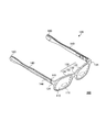
- a perspective view which shows an example of a structure of the electronic glasses which concern on this embodiment
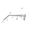
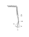
- Top view and partial perspective view of electronic glasses Partial perspective view of electronic glasses viewed from the right side
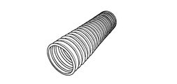
- Side view of a flexible tube which is a member formed of a thin metal plate and has a gap (slit) with a predetermined width along the long axis direction
- eyewear means an instrument that is worn on the eye and used for eyesight correction, eye protection, video viewing, etc.
- virtual wear It includes VR glasses for experiencing space (VR) / augmented reality (AR), smart glasses / headsets for displaying images, and the like.
- VR glasses for experiencing space (VR) / augmented reality (AR), smart glasses / headsets for displaying images, and the like.
- electronic glasses having a lens including an electroactive region whose optical characteristics can be changed by electrical control will be described as an example of eyewear.
- FIG. 1 is a perspective view illustrating an example of the configuration of the electronic glasses 100 according to the present embodiment.
- the electronic glasses 100 includes a pair of lenses 110, a frame 120, and an electronic component 160.
- the frame 120 has a front 130 and a pair of temples 140. In the following description, a portion where the front 130 is disposed will be described as the front (front) of the electronic glasses 100.
- Lens The pair of lenses 110 are formed to be bilaterally symmetric when the electronic glasses 100 are viewed from the front, and have the same components.
- the lens 110 has a liquid crystal lens 111 and a pair of electrodes (not shown).
- the liquid crystal lens 111 has a multilayer structure, and has at least a pair of conductive layers (not shown) that sandwich a liquid crystal layer (not shown) from the front and back. Each of the pair of conductive layers is connected to the electrode. When a voltage is applied between the pair of conductive layers, the liquid crystal layer is activated and the refractive index of the liquid crystal lens 111 changes.
- a transparent electrode such as ITO is used as the electrode.
- the liquid crystal lens 111 is an example of the electric element of the present invention, and may be a display device or the like.
- the lens 110 is formed by being cut out from a lens blank so as to have a shape that matches the shape of a rim 131 described later.
- the front 130 holds a pair of lenses 110.
- the front 130 includes a pair of rims 131 that respectively support the pair of lenses 110 and a bridge 132 that connects the pair of rims 131 to each other.
- the shape of the rim 131 is a shape corresponding to the shape of the lens 110.
- the bridge 132 has a pair of nose pads 133 that can contact the user's nose.
- wiring for electrically connecting the electrode of the lens 110 and a control unit 150 (described later) is disposed inside the front 130.
- the material of the front 130 constituting the frame 120 is not particularly limited, but a material having thermoplasticity and capable of adjusting the position and shape of each part as necessary is preferable.
- a known material used as a front material of glasses can be used.
- the material of the front 130 include polyamide, acetate, carbon, celluloid, polyetherimide, and urethane.
- the front 130 has wisdom 134 in the vicinity of both ends thereof.
- the wisdom 134 is a part extending toward the left or right and rearward as viewed from the rim 131.
- the rear end of the wisdom 134 is connected to the temple 140 by a hinge 141.
- temple 140 is formed so as to have a substantially symmetrical outer shape in the electronic glasses 100. As shown in FIG. 1, the temple 140 is rotatably connected to the front 130 at the hinge 141 at the front end thereof. In addition, the front or back in description of the following temple 140 means the front or back in the state (The state shown by FIGS. 1-3) where the temple 140 was expand
- the material of the temple 140 constituting the frame 120 is not particularly limited, but a material such as a resin that has thermoplasticity and can adjust the position and shape of each part as necessary is preferable.
- a material such as a resin that has thermoplasticity and can adjust the position and shape of each part as necessary is preferable.
- a known material used as the material of the temple of the glasses for example, the same material as that of the material of the front 130 can be used.
- a transparent or translucent material as the material of the temple 140, for example, it is possible to confirm the fitting state of the coil spring 200, which will be described later, the degree of bending of the coil spring 200, and the like.
- marking, markings, patterns, manufacturing information, product information, serial numbers, barcodes, etc. improve the design of the temple 140, improve the traceability of the product and prevent counterfeiting. It is also possible to do.
- the outer shape of the temple 140 is constituted by a housing 142.
- the housing 142 accommodates the control unit 150, the wiring 151, and the coil spring 200.
- FIG. 2 is a plan view and a partial perspective view of the electronic glasses 100.
- FIG. 3 is a partial perspective view of the electronic glasses 100 viewed from the right side. 2 and 3, the control unit 150, the wiring 151, and the coil spring 200 housed in the housing 142 of the temple 140 are shown in a state where the housing 142 is seen through.
- the control unit 150, the wiring 151, and the coil spring 200 are illustrated only in the right temple 140 as viewed from the user of the electronic glasses 100.
- an ear hook 143 is formed.
- the ear hook 143 is integrally formed as a part of the casing 142 of the temple 140, but the present invention is not limited to this.
- the ear hook 143 may be formed separately from the same material as or different from that of the housing 142 and attached to the rear end of the temple 140.
- a contacted portion 144 is provided near the front end of the temple 140.
- the contacted part 144 is a part that can be contacted by an object such as a user's finger for operating the electronic glasses 100, for example. For this reason, as shown in FIG. 1, at least a part of the contacted portion 144 is arranged to be exposed to the outside of the housing 142.
- the position of the contacted part 144 is preferably a position where the user of the electronic glasses 100 can easily touch the contacted part 144. From such a viewpoint, the contacted portion 144 is disposed on the front side of the midpoint of the casing 142 in the long axis direction. Further, the contacted portion 144 is disposed on the outer surface of the housing 142 as viewed from the user of the electronic glasses 100.
- the shape of the contacted part 144 is not particularly limited. In the present embodiment, the contacted portion 144 extends along the long axis direction of the housing 142.
- the contacted portion 144 is not particularly limited, and is, for example, a capacitive touch sensor or a mechanical switch. In this embodiment, as an example, a case where the contacted portion 144 is a capacitive touch sensor will be described. In this case, the contact of the target object, which is a conductor, with the contacted portion 144 is electrically transmitted to the control unit 150. For this reason, the to-be-contacted part 144 has electroconductivity. Examples of the material of the contacted portion 144 include gold, silver, copper, aluminum, and alloys thereof. In this case, it is preferable that the material of at least the peripheral portion (for example, the temple 140) of the contacted portion 144 is insulative.
- the control unit 150 is configured by, for example, a CPU or the like, and controls detection of a change in capacitance in the contacted portion 144 and application of a voltage to the liquid crystal lens 111. Specifically, for example, when the contacted portion 144 detects contact of an object, the control unit 150 performs control to apply a voltage to the liquid crystal lens 111 or stop the application of the voltage, so that the liquid crystal lens The refractive index of 111 is switched.
- the electrical element of the present invention is a display device (not shown)
- the control unit 150 applies a voltage to the display device when the contacted portion 144 detects contact of an object, and displays an image or the like.
- Control is performed to display an image or the like by transmitting an information signal, or control to stop application of voltage or transmission of an information signal, display of a video on a display device, switching of a video, or the like. Further, the control unit 150 operates and controls various electronic components 160 described later.
- the control unit 150 is accommodated in the vicinity of the front end of the housing 142.
- the wiring 151 electrically connects the control unit 150 and the electronic component 160.
- the wiring 151 is, for example, a covered electric wire or a flexible printed wiring board (FPC) in which the periphery of the conducting wire is covered with an insulating covering member. As shown in FIGS. 2 and 3, the wiring 151 is housed in an insulated state inside a coil spring 200 formed in a cylindrical shape.
- the electronic component 160 is various electronic components related to the function of the electronic glasses 100.
- Examples of the electronic component 160 include the following.
- a power supply for supplying power to the control unit 150 and the liquid crystal lens 111 a memory as a storage unit for storing various information (for example, a reader / writer that reads and writes an external storage device such as a flash memory or a memory card), WiFi , Bluetooth (registered trademark), a wireless communication device as a communication unit that provides a wireless communication function such as NFC (near field communication), the above-described control unit 150 (applies a voltage to the liquid crystal lens 111 or applies the voltage)
- the second control unit for example, a device that switches the refractive index of the liquid crystal lens 111 is controlled to change the color of the lens by applying a voltage to the liquid crystal lens 111.
- Second contacted part second touch sensor part
- camera microphone
- speaker including bone conduction type speakers in addition to conventional sound emitting speakers
- Hearing aids sound collectors
- various sensors acceleration sensor, tilt sensor, heart rate sensor, GPS, thermometer, myoelectric sensor, etc.
- the following forms are conceivable as usage forms of the electronic glasses 100 having the electronic component 160 exemplified above. That is, for example, the user's activity state (acceleration sensor, tilt sensor, information on the user's movement and position obtained by GPS, etc.) and body state (heart rate sensor, thermometer, myoelectricity obtained by various sensors)
- the control unit 150 obtains information about the user's body and health obtained by sensors or the like at all times or in a timely manner, stores it in a memory, and stores it in an external network or electronic device (user's smartphone) Or acquired information on a wearable terminal or the like). According to such a usage pattern, the usability of the electronic glasses 100 is greatly improved.
- 1 to 3 exemplify a power source that is a rechargeable battery pack that is detachably held at the rear end of the housing 142 as the electronic component 160.
- the power source include a nickel metal hydride rechargeable battery, a lithium ion rechargeable battery, and a solar battery.
- 1 to 3 show an example in which the electronic component 160, which is a detachable battery pack, is held at the rear end of the housing 142, the position where the electronic component 160 is arranged is described in the present invention. Then there is no particular limitation. For example, in the case of a memory, a wireless communication device, a second control unit, etc., they may be arranged at the same position as the control unit 150.
- the electronic component 160 when the electronic component 160 is a camera, a microphone, a speaker, a hearing aid, various sensors, etc., the electronic component 160 should just be arrange
- the camera and the microphone may be arranged at a part of the front 130
- the speaker and the hearing aid may be arranged at a part of the ear hook 143.
- the coil spring 200 is a spring formed in a hollow cylindrical shape, and is formed in a cylindrical shape, for example.
- the coil spring 200 is an example of the hollow member of the present invention.
- the coil spring 200 is not particularly limited.
- the rear end portion of the housing 142 that is, the ear hooking portion 143, from the rear side of the control unit 150. It is arranged up to the tip.
- the wiring 151 is accommodated in the coil spring 200 in a state insulated from the coil spring 200.
- the wiring 151 that connects the control unit 150 housed near the front end of the housing 142 and the electronic component 160 attached to the rear end of the housing 142 is physically protected by the coil spring 200. Is done.
- the coil spring 200 should just be arrange
- the coil spring 200 is made of metal. For this reason, the strength of the temple 140 is ensured by arranging the coil spring 200 in the housing 142.
- the coil spring 200 has elasticity. Thereby, when the necessity for adjustment (fitting) for fitting the ear hook 143 to the ear shell arises, the coil spring 200 follows the housing 142 and easily elastically deforms.
- FIG. 4 is a diagram for explaining a change in the position of the ear hook 143 when a force is applied from the outside to the ear hook 143 for fitting the ear hook 143.
- FIG. 4 is a plan view of the electronic glasses 100. As shown in FIG. 4, when fitting the ear hanger 143, the ear hanger 143 is deformed inward or outward in a plan view of the electronic glasses 100. Thereby, what is called a holding angle can be adjusted suitably.
- the coil spring 200 easily elastically deforms following the deformed ear hook 143. For this reason, the presence of the coil spring 200 does not hinder the fitting of the ear hook 143, and the fitting of the ear hook 143 can be suitably performed.
- the deformation of the coil spring 200 is an elastic deformation, even if the fitting of the ear hook portion 143 is performed a plurality of times, no bending wrinkles remain, and a situation in which the outer shape of the temple 140 is affected by the bending wrinkles is avoided.
- the holding angle is adjusted by deforming the ear hanger 143 outward or inward when viewed from the user in the plan view of the electronic glasses 100 is illustrated. It is not limited to.
- the so-called sagging angle may be adjusted by deforming the temple 140 upward or downward.
- both the holding angle and the depression angle may be adjusted at the same time.
- An example of a method for manufacturing the housing 142 in which the coil spring 200 is disposed is insert molding, for example. That is, the coil spring 200 is inserted into a mold (not shown) formed in accordance with the outer dimensions of the casing 142 in advance, and a material is injected around the mold to form the casing.
- the body 142 can be manufactured.
- the electronic glasses 100 controls the lens 110 having the liquid crystal lens 111, the temple 140 that holds the lens 110 and is formed hollow, and the liquid crystal lens 111 is controlled.
- the electronic component 160 electrically connected to the control unit 150 via the wiring 151, and the wiring 151 in the state where the wiring 151 is housed inside the temple 140, and the ear hook 143 for fitting.
- the coil spring 200 that elastically deforms following the deformation of the ear hook portion 143.
- the wire 151 can be physically protected by the coil spring 200 and the strength of the temple 140 can be secured.
- the coil spring 200 is elastically deformed following the housing 140, so that the ear hook 143 can be suitably fitted. Furthermore, even if the fitting of the ear hook part 143 is performed a plurality of times, the deformation of the coil spring 200 is an elastic deformation, so that no bending wrinkles remain, and a situation in which the outer shape of the temple 140 is affected by the bending wrinkles is avoided.
- the coil spring 200 is shown as an example of a hollow member for securing the strength of the temple 140, protecting the wiring 151, and suitably fitting the ear hook 143.
- the present invention is not limited to this.
- an annular member made of a metal or a resin having a S-shaped cross section is joined, a metal plate or a resin plate is processed into a corrugated shape, a metal tube or a resin tube is You may employ
- a flexible tube having a predetermined width along the major axis direction which is a member formed of a thin metal plate or a thin resin plate in a cylindrical shape, may be disposed inside the temple 140. Even when such a member is arranged inside the temple 140, the same effect as when the coil spring 200 is employed can be obtained.
- a material other than metal such as a pipe-shaped resin, may be used. In this case, the hollow member may not have elasticity.
- materials other than metals, such as resin for a hollow member, you may use the same material as the temple 140, For example, you may use the material which has a different physical property from the temple 140.
- the stability of the fitting can be improved.
- the ease of fitting can be improved by using for the hollow member the resin material whose bending elastic modulus or Young's modulus is lower than the resin material of the temple 140.
- FIG. 5A to 5E are diagrams illustrating configurations for ensuring the strength of the temple 140, protecting the wiring 151, and suitably fitting the ear hooking portion 143, including the coil spring 200 of the above-described embodiment.
- FIG. 5A is a perspective view illustrating the coil spring 200.
- FIG. 5B is a perspective view of the flexible tube.
- FIG. 5C is a cross-sectional view of a flexible tube in which metal annular members whose cross sections are formed in an S shape are joined together.
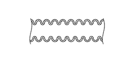
- FIG. 5D is a cross-sectional view of a flexible tube obtained by processing a metal plate into a cross-sectional corrugated shape (bellows type, that is, bellows).
- 5E is a side view of a flexible tube which is a member in which a thin metal plate is formed in a cylindrical shape and has a gap (slit) having a predetermined width along the long axis direction.
- the electronic glasses 100 secures the strength of the temple 140, protects the wiring 151, and fits the ear hook 143, regardless of the configuration illustrated in FIGS. 5A to 5E. It can be suitably performed.
- a coaxial cable may be employ
- the coil spring 200 is arranged from the rear side of the control unit 150 from the rear end portion of the casing 142, that is, the ear hooking portion. It arrange
- the present invention is not limited to this.
- the coil spring 200 is disposed at the position serving as the fulcrum. It only has to be done.
- the fulcrum of deformation of the ear hook 143 is the vicinity of the base of the ear hook 143, that is, the vicinity of the position where the ear hook 143 begins to bend according to the shape of the user's ear shell (the bent portion shown in FIG. 4). 143B).
- a metal pipe (not shown) may be disposed inside the other portion of the temple 140. Further, the coil spring 200 and the metal pipe may be connected. Thereby, the intensity
- the coil spring 200 is disposed in the temple 140 for the purpose of suitably fitting the ear hook 143, but the present invention is not limited to this.
- the coil spring 200 may be configured so that not only the ear hook 143 but also the entire temple 140 can be fitted. In this case, it is desirable that the coil spring 200 is disposed at a location serving as a fulcrum for deformation of at least a portion of the temple 140 that requires adjustment.
- the coil spring 200 may be disposed other than the temple 140 of the frame 120. Specifically, the coil spring 200 may be disposed inside the bridge 132, for example. With such a configuration, the electronic glasses 100 can be deformed so as to change the angle formed by the left and right rims 131 connected by the bridge 132 in a plan view. As a result, it is possible to perform fitting that improves the appearance and comfort of the electronic glasses 100.
- the wiring 151 is accommodated in the coil spring 200 formed in a cylindrical shape and the control unit 150 is not accommodated, but the present invention is not limited to this. If the outer dimensions of the housing 142 allow by design, the control unit 150 may be housed inside the coil spring 200. In this case, for example, the control unit 150 which is a circuit board can be physically protected by the coil spring 200, which is more preferable.
- FIG. 2 illustrates the control unit 150, the wiring 151, and the coil spring 200 only in the right temple 140 as viewed from the user of the electronic glasses 100.
- a similar configuration may be arranged on the left temple 140.
- the control unit 150 is disposed only on either the right side or the left side of the temple 140, in the temple 140 on the side where the control unit 150 is not disposed, the coil spring 200 is entirely along the long axis direction of the temple 140. It may be arranged.
- the present invention is suitable as eyewear including a lens having an electric element.
Landscapes
- Physics & Mathematics (AREA)
- Health & Medical Sciences (AREA)
- General Physics & Mathematics (AREA)
- Ophthalmology & Optometry (AREA)
- Optics & Photonics (AREA)
- General Health & Medical Sciences (AREA)
- Nonlinear Science (AREA)
- Acoustics & Sound (AREA)
- Otolaryngology (AREA)
- Eyeglasses (AREA)
- Liquid Crystal (AREA)
Abstract
Description
図1は、本実施形態に係る電子メガネ100の構成の一例を示す斜視図である。電子メガネ100は、一対のレンズ110と、フレーム120と、電子部品160とを有する。フレーム120は、フロント130、および一対のテンプル140を有する。なお、以下の説明では、フロント130が配置されている部分を電子メガネ100の正面(前方)として説明する。
一対のレンズ110は、電子メガネ100を正面視したときに左右対称となるように形成されており、互いに同一の構成要素を有する。
図1に示されるように、フロント130は、一対のレンズ110を保持している。フロント130は、一対のレンズ110をそれぞれ支持している一対のリム131と、一対のリム131を互いに接続しているブリッジ132とを有する。リム131の形状は、レンズ110の形状に対応する形状である。ブリッジ132は、使用者の鼻に接触しうる一対の鼻パッド133を有する。特に図示しないが、フロント130の内部には、レンズ110の電極と後述の制御部150とを電気的に接続するための配線が配置されている。
左右一対のテンプル140は、電子メガネ100においてほぼ左右対称の外形を有するように形成されている。図1に示されるように、テンプル140は、その前端部のヒンジ141においてフロント130に回転可能に接続されている。なお、以下のテンプル140の説明における前または後ろは、テンプル140が展開された状態(図1から図3に示される状態)における前または後ろを意味する。
制御部150は、例えば、CPU等によって構成され、被接触部144における静電容量の変化の検出と、液晶レンズ111への電圧の印加とを制御する。具体的には、制御部150は、例えば、被接触部144が対象物の接触を検出したときに、液晶レンズ111に電圧を印加する、またはその電圧の印加を停止する制御を行い、液晶レンズ111の屈折率を切り替える。例えば、本発明の電気素子が表示装置(不図示)である場合は、制御部150は、被接触部144が対象物の接触を検出したときに、表示装置に電圧を印加し、映像等の情報信号を送信して映像等を表示する制御をしたり、電圧印加・情報信号の送信を停止する制御を行い、表示装置への映像の表示・映像の切り替え等を行ったりする。また、制御部150は、後述の各種の電子部品160の操作・制御を行う。
配線151は、制御部150と、電子部品160とを電気的に接続する。配線151は、例えば導線の周囲を絶縁性の被覆部材で覆った被覆電線やフレキシブルプリント配線板(FPC)である。図2および図3に示すように、配線151は、筒状に形成されたコイルバネ200の内部に、絶縁された状態で収容されている。
電子部品160は、電子メガネ100の機能に関わる種々の電子部品である。電子部品160の例としては、以下のようなものがある。例えば、制御部150および液晶レンズ111に電力を供給する電源、各種情報を記憶する記憶部としてのメモリ(例えば、フラッシュメモリやメモリカード等の外部記憶装置を読み書きするリーダ/ライタを含む)、WiFiやブルートゥース(登録商標)、NFC(近距離無線通信)等の無線通信機能を提供する通信部としての無線通信装置、上述の制御部150(液晶レンズ111に電圧を印加する、またはその電圧の印加を停止する制御を行い、液晶レンズ111の屈折率を切り替える装置)とは異なる制御を行う第二の制御部(例えば、液晶レンズ111を電圧を印加することによりレンズの色を変化・調光させるエレクトロクロミックレンズに交換した場合や、後述のカメラやマイク、液晶ディスプレイ等を操作・制御する場合に、それらの電子部品の動作を制御する装置)、第二の被接触部(第二のタッチセンサー部)、カメラ、マイク、スピーカ(従来の音を発するスピーカのほか、骨伝導式スピーカを含む)、補聴器(集音器)、各種センサ(加速度センサ、傾斜センサ、心拍センサ、GPS、体温計、筋電センサ等)がある。
コイルバネ200は、中空の筒形状に形成されたバネであり、例えば円筒形状に形成されている。コイルばね200は、本発明の中空部材の一例である。図2および図3に示すように、コイルバネ200は、特に制限されないが、例えば、筐体142の内部において、制御部150より後ろ側から、筐体142の後端部、すなわち耳掛け部143の先端部まで配置されている。上記したように、コイルバネ200の内部には、配線151がコイルバネ200と絶縁された状態で収容されている。このような構成により、筐体142の前端部付近に収容された制御部150と筐体142の後端部に取り付けられた電子部品160とを接続する配線151は、コイルバネ200によって物理的に保護される。なお、コイルバネ200は、少なくとも、使用者へのフィッティングのために曲げられる電子メガネ100のテンプル140の一部の領域において、筐体142の内部に配置されていればよい。
以上説明したように、本発明の実施形態に係る電子メガネ100は、液晶レンズ111を有するレンズ110と、レンズ110を保持し、中空に形成されたテンプル140と、液晶レンズ111の制御を行う制御部150と、制御部150と配線151を介して電気的に接続される電子部品160と、配線151を内部に収容した状態でテンプル140の内部に配置されており、フィッティングのため耳掛け部143が変形されるとき、耳掛け部143の変形に追従して弾性変形するコイルバネ200と、を有する。
以上、図面を参照しながら本発明の実施形態について説明したが、本発明はかかる例に限定されない。当業者であれば、特許請求の範囲に記載された範囲内において、各種の変更例または修正例に想到しうることは明らかであり、それらについても当然に本発明の技術的範囲に属するものと了解される。また、発明の趣旨を逸脱しない範囲において、上記実施形態における各構成要素は任意に組み合わせられてもよい。
110 レンズ
111 液晶レンズ
120 フレーム
130 フロント
131 リム
132 ブリッジ
133 鼻パッド
134 智
140 テンプル
141 ヒンジ
142 筐体
143 耳掛け部
144 被接触部
150 制御部
151 配線
160 電子部品
200 コイルバネ
Claims (17)
- 電気素子を有するレンズと、
前記レンズを保持し、一部が中空に形成されたフレームと、
前記電気素子の制御を行う制御部と、
前記制御部と配線を介して電気的に接続される電子部品と、
前記配線を内部に収容した状態で前記フレームの内部に配置されており、前記フレームの変形に追従して変形する中空部材と、
を有するアイウェア。 - 前記中空部材は、前記フレームの変形に追従して弾性変形する、
請求項1に記載のアイウェア。 - 前記中空部材は、金属で形成される、
請求項1または2に記載のアイウェア。 - 前記中空部材は、テンプルの内部に配置される、
請求項1から3のいずれか一項に記載のアイウェア。 - 前記テンプルは屈曲部を有する耳掛け部を含み、
前記中空部材は、前記屈曲部に配置される、
請求項4に記載のアイウェア。 - 前記中空部材は、ブリッジの内部に配置される、
請求項1に記載のアイウェア。 - 前記中空部材は、コイルバネである、
請求項1から6のいずれか一項に記載のアイウェア。 - 前記中空部材は、前記テンプルの耳掛け部の屈曲部を含む所定の範囲において前記フレームの変形に追従して弾性変形する弾性変形領域を有し、かつ、前記テンプルの耳掛け部の屈曲部を含む所定の範囲以外の範囲において前記フレームの変形に追従して変形する非弾性変形領域を有する、
請求項4または5に記載のアイウェア。 - 前記弾性変形領域は、コイルバネで形成され、
前記非弾性変形領域は、金属パイプで形成され、
かつ、前記弾性変形領域と前記非弾性変形領域とが連結されている、
請求項8に記載のアイウェア。 - 電気素子を有するレンズと、
前記レンズを保持し、一部が中空に形成されたフレームと、
前記電気素子の制御を行う制御部と、
前記制御部と配線を介して電気的に接続される電子部品と、
前記配線を内部に収容した状態で前記フレームの内部に配置されており、前記フレームの変形に追従して変形するフレキシブルチューブと、
を有するアイウェア。 - 前記フレキシブルチューブは、断面がS字型に形成された金属環状部材を繋ぎ合わせて形成された、
請求項10に記載のアイウェア。 - 前記フレキシブルチューブは、金属板を断面波型に加工して形成された、
請求項10に記載のアイウェア。 - 前記フレキシブルチューブは、金属管を蛇腹型に加工して形成された、
請求項10に記載のアイウェア。 - 前記フレキシブルチューブは、金属薄板を筒状に形成した部材であって、長軸方向に沿って所定の幅の隙間を有する部材である、
請求項10に記載のアイウェア。 - 前記フレキシブルチューブは、同軸ケーブルである、
請求項10に記載のアイウェア。 - 前記電子部品は、前記制御部に電力を供給する電源である、
請求項1から15のいずれ一項に記載のアイウェア。 - 前記電子部品は、アイウェアの使用者の身体情報を取得するセンサである、
請求項1から16のいずれか一項に記載のアイウェア。
Priority Applications (4)
| Application Number | Priority Date | Filing Date | Title |
|---|---|---|---|
| JP2020507369A JP7015378B2 (ja) | 2018-03-22 | 2019-01-11 | アイウェア |
| EP19770706.0A EP3770671A4 (en) | 2018-03-22 | 2019-01-11 | Eyewear |
| US17/040,061 US11953757B2 (en) | 2018-03-22 | 2019-01-11 | Eyewear |
| CN201980011661.5A CN111684340A (zh) | 2018-03-22 | 2019-01-11 | 眼睛佩戴物 |
Applications Claiming Priority (2)
| Application Number | Priority Date | Filing Date | Title |
|---|---|---|---|
| JP2018055006 | 2018-03-22 | ||
| JP2018-055006 | 2018-03-22 |
Publications (1)
| Publication Number | Publication Date |
|---|---|
| WO2019181150A1 true WO2019181150A1 (ja) | 2019-09-26 |
Family
ID=67986959
Family Applications (1)
| Application Number | Title | Priority Date | Filing Date |
|---|---|---|---|
| PCT/JP2019/000691 WO2019181150A1 (ja) | 2018-03-22 | 2019-01-11 | アイウェア |
Country Status (5)
| Country | Link |
|---|---|
| US (1) | US11953757B2 (ja) |
| EP (1) | EP3770671A4 (ja) |
| JP (1) | JP7015378B2 (ja) |
| CN (1) | CN111684340A (ja) |
| WO (1) | WO2019181150A1 (ja) |
Cited By (5)
| Publication number | Priority date | Publication date | Assignee | Title |
|---|---|---|---|---|
| WO2021084488A1 (en) * | 2019-10-31 | 2021-05-06 | Facense Ltd. | Smartglasses for detecting physiological parameters |
| JP2021117446A (ja) * | 2020-01-29 | 2021-08-10 | 三井化学株式会社 | アイウェア |
| US11103140B2 (en) | 2015-06-14 | 2021-08-31 | Facense Ltd. | Monitoring blood sugar level with a comfortable head-mounted device |
| US11154203B2 (en) | 2015-06-14 | 2021-10-26 | Facense Ltd. | Detecting fever from images and temperatures |
| US11604367B2 (en) | 2020-04-08 | 2023-03-14 | Facense Ltd. | Smartglasses with bendable temples |
Families Citing this family (3)
| Publication number | Priority date | Publication date | Assignee | Title |
|---|---|---|---|---|
| US11449826B2 (en) * | 2019-03-15 | 2022-09-20 | Hashim Muhammad SIDDIQUI | Systems and methods for autonomous inventory counting and tracking |
| CN114545661A (zh) * | 2022-03-08 | 2022-05-27 | 西安建筑科技大学 | 一种基于超声波测距动态调整度数的眼镜 |
| EP4375797A1 (en) * | 2022-10-11 | 2024-05-29 | Samsung Electronics Co., Ltd. | Wearable device comprising speaker |
Citations (11)
| Publication number | Priority date | Publication date | Assignee | Title |
|---|---|---|---|---|
| JPS5867313U (ja) * | 1981-10-29 | 1983-05-07 | 株式会社 佐々木セルロイド工業所 | 眼鏡におけるつる |
| JPS58128412U (ja) * | 1982-02-22 | 1983-08-31 | 株式会社 佐々木セルロイド工業所 | 眼鏡枠 |
| JPH0545637U (ja) * | 1991-11-25 | 1993-06-18 | 株式会社大日工業 | 眼鏡フレームの耳掛装置 |
| US6513926B1 (en) * | 2002-07-30 | 2003-02-04 | Umeda Inc. | Double-foldable eyeglasses |
| JP2008009044A (ja) * | 2006-06-28 | 2008-01-17 | Kiyohiko Tsuji | 眼鏡セル(テンプルおよびモダン) |
| JP2008096598A (ja) * | 2006-10-10 | 2008-04-24 | Hoya Corp | 眼鏡フレーム |
| JP2009092946A (ja) | 2007-10-09 | 2009-04-30 | Nojiri Optical Co Ltd | 眼鏡フレームのバネ付勢式モダン角度調整機構 |
| US20110088820A1 (en) * | 2009-10-16 | 2011-04-21 | Eli Khuri | Spectacles temple protector |
| JP2015522842A (ja) * | 2012-06-14 | 2015-08-06 | 三井化学株式会社 | 電子眼鏡及び製造方法 |
| JP2017134100A (ja) * | 2016-01-25 | 2017-08-03 | 富士フイルム株式会社 | 空気送出機能付き眼鏡 |
| JP2018055006A (ja) | 2016-09-30 | 2018-04-05 | 株式会社沖データ | 定着装置および画像形成装置 |
Family Cites Families (5)
| Publication number | Priority date | Publication date | Assignee | Title |
|---|---|---|---|---|
| US3825700A (en) * | 1973-03-02 | 1974-07-23 | Sonotone Corp | Articulated hearing aid temple and behind-the-ear hearing aid element |
| US5781272A (en) | 1997-06-06 | 1998-07-14 | Safety+Plus, Inc. | Eyesight protection apparatus with attached earplugs |
| FR3027412A1 (fr) * | 2014-10-21 | 2016-04-22 | Arch | Branche pour lunette de vue. |
| US20190041666A1 (en) * | 2017-12-28 | 2019-02-07 | Nicolas Abele | Electronically reinforced head-wearable apparatus and related methods |
| EP3750028B1 (en) * | 2018-02-09 | 2022-10-19 | Pupil Labs GmbH | Devices, systems and methods for predicting gaze-related parameters |
-
2019
- 2019-01-11 EP EP19770706.0A patent/EP3770671A4/en not_active Withdrawn
- 2019-01-11 CN CN201980011661.5A patent/CN111684340A/zh active Pending
- 2019-01-11 JP JP2020507369A patent/JP7015378B2/ja active Active
- 2019-01-11 WO PCT/JP2019/000691 patent/WO2019181150A1/ja active Application Filing
- 2019-01-11 US US17/040,061 patent/US11953757B2/en active Active
Patent Citations (11)
| Publication number | Priority date | Publication date | Assignee | Title |
|---|---|---|---|---|
| JPS5867313U (ja) * | 1981-10-29 | 1983-05-07 | 株式会社 佐々木セルロイド工業所 | 眼鏡におけるつる |
| JPS58128412U (ja) * | 1982-02-22 | 1983-08-31 | 株式会社 佐々木セルロイド工業所 | 眼鏡枠 |
| JPH0545637U (ja) * | 1991-11-25 | 1993-06-18 | 株式会社大日工業 | 眼鏡フレームの耳掛装置 |
| US6513926B1 (en) * | 2002-07-30 | 2003-02-04 | Umeda Inc. | Double-foldable eyeglasses |
| JP2008009044A (ja) * | 2006-06-28 | 2008-01-17 | Kiyohiko Tsuji | 眼鏡セル(テンプルおよびモダン) |
| JP2008096598A (ja) * | 2006-10-10 | 2008-04-24 | Hoya Corp | 眼鏡フレーム |
| JP2009092946A (ja) | 2007-10-09 | 2009-04-30 | Nojiri Optical Co Ltd | 眼鏡フレームのバネ付勢式モダン角度調整機構 |
| US20110088820A1 (en) * | 2009-10-16 | 2011-04-21 | Eli Khuri | Spectacles temple protector |
| JP2015522842A (ja) * | 2012-06-14 | 2015-08-06 | 三井化学株式会社 | 電子眼鏡及び製造方法 |
| JP2017134100A (ja) * | 2016-01-25 | 2017-08-03 | 富士フイルム株式会社 | 空気送出機能付き眼鏡 |
| JP2018055006A (ja) | 2016-09-30 | 2018-04-05 | 株式会社沖データ | 定着装置および画像形成装置 |
Non-Patent Citations (1)
| Title |
|---|
| See also references of EP3770671A4 |
Cited By (6)
| Publication number | Priority date | Publication date | Assignee | Title |
|---|---|---|---|---|
| US11103140B2 (en) | 2015-06-14 | 2021-08-31 | Facense Ltd. | Monitoring blood sugar level with a comfortable head-mounted device |
| US11154203B2 (en) | 2015-06-14 | 2021-10-26 | Facense Ltd. | Detecting fever from images and temperatures |
| WO2021084488A1 (en) * | 2019-10-31 | 2021-05-06 | Facense Ltd. | Smartglasses for detecting physiological parameters |
| JP2021117446A (ja) * | 2020-01-29 | 2021-08-10 | 三井化学株式会社 | アイウェア |
| JP7440721B2 (ja) | 2020-01-29 | 2024-02-29 | カール ツァイス ヴィジョン インターナショナル ゲーエムベーハー | アイウェア |
| US11604367B2 (en) | 2020-04-08 | 2023-03-14 | Facense Ltd. | Smartglasses with bendable temples |
Also Published As
| Publication number | Publication date |
|---|---|
| US11953757B2 (en) | 2024-04-09 |
| EP3770671A4 (en) | 2021-12-29 |
| JP7015378B2 (ja) | 2022-02-02 |
| JPWO2019181150A1 (ja) | 2021-01-07 |
| EP3770671A1 (en) | 2021-01-27 |
| US20210026157A1 (en) | 2021-01-28 |
| CN111684340A (zh) | 2020-09-18 |
Similar Documents
| Publication | Publication Date | Title |
|---|---|---|
| WO2019181150A1 (ja) | アイウェア | |
| JP6513195B2 (ja) | 眼鏡型電子機器 | |
| EP2942931B1 (en) | Mobile terminal with eyeglass display | |
| JP6383490B2 (ja) | 眼鏡型電子機器 | |
| WO2013134204A1 (en) | Eyeglass frame with input and output functionality | |
| JP2013030920A (ja) | 無線通信機 | |
| JP2007304587A (ja) | 電気活性なレンズのための電子機器を収容する眼鏡フレームのブリッジ | |
| US11294199B2 (en) | Eyewear | |
| JP6896086B2 (ja) | アイウェア | |
| JP7015329B2 (ja) | 検眼用レンズユニットおよび検眼用レンズセット | |
| US20210041723A1 (en) | Eyewear system | |
| CN113474717B (zh) | 接触镜、接触镜对和穿戴设备 | |
| WO2015170662A1 (ja) | 人体特性検出装置及び眼鏡型電子機器 | |
| CN112684603B (zh) | 智能眼镜 | |
| JP2017037225A (ja) | 頭部装着型デバイス | |
| KR20240014414A (ko) | 렌즈 배럴을 포함하는 웨어러블 전자 장치 | |
| KR20230101641A (ko) | 웨어러블 전자 장치 | |
| KR20230115856A (ko) | 웨어러블 전자 장치 및 이를 수용하는 외부 전자 장치 | |
| KR20230055091A (ko) | 안테나를 포함하는 웨어러블 전자 장치 | |
| JP2009237449A (ja) | 電子眼鏡 |
Legal Events
| Date | Code | Title | Description |
|---|---|---|---|
| 121 | Ep: the epo has been informed by wipo that ep was designated in this application |
Ref document number: 19770706 Country of ref document: EP Kind code of ref document: A1 |
|
| ENP | Entry into the national phase |
Ref document number: 2020507369 Country of ref document: JP Kind code of ref document: A |
|
| NENP | Non-entry into the national phase |
Ref country code: DE |
|
| WWE | Wipo information: entry into national phase |
Ref document number: 2019770706 Country of ref document: EP |
|
| ENP | Entry into the national phase |
Ref document number: 2019770706 Country of ref document: EP Effective date: 20201022 |