WO2019172062A1 - 眼底撮影装置 - Google Patents
眼底撮影装置 Download PDFInfo
- Publication number
- WO2019172062A1 WO2019172062A1 PCT/JP2019/007760 JP2019007760W WO2019172062A1 WO 2019172062 A1 WO2019172062 A1 WO 2019172062A1 JP 2019007760 W JP2019007760 W JP 2019007760W WO 2019172062 A1 WO2019172062 A1 WO 2019172062A1
- Authority
- WO
- WIPO (PCT)
- Prior art keywords
- mode
- fundus
- light
- optical system
- imaging apparatus
- Prior art date
- Legal status (The legal status is an assumption and is not a legal conclusion. Google has not performed a legal analysis and makes no representation as to the accuracy of the status listed.)
- Ceased
Links
Images




Classifications
-
- A—HUMAN NECESSITIES
- A61—MEDICAL OR VETERINARY SCIENCE; HYGIENE
- A61B—DIAGNOSIS; SURGERY; IDENTIFICATION
- A61B3/00—Apparatus for testing the eyes; Instruments for examining the eyes
- A61B3/10—Objective types, i.e. instruments for examining the eyes independent of the patients' perceptions or reactions
- A61B3/102—Objective types, i.e. instruments for examining the eyes independent of the patients' perceptions or reactions for optical coherence tomography [OCT]
-
- A—HUMAN NECESSITIES
- A61—MEDICAL OR VETERINARY SCIENCE; HYGIENE
- A61B—DIAGNOSIS; SURGERY; IDENTIFICATION
- A61B3/00—Apparatus for testing the eyes; Instruments for examining the eyes
- A61B3/10—Objective types, i.e. instruments for examining the eyes independent of the patients' perceptions or reactions
- A61B3/12—Objective types, i.e. instruments for examining the eyes independent of the patients' perceptions or reactions for looking at the eye fundus, e.g. ophthalmoscopes
Definitions
- the present disclosure relates to a fundus imaging apparatus.
- Patent Document 1 discloses an apparatus in which a region on the fundus to be photographed is switched between a first field angle and a larger second field angle.
- the lens system is inserted and removed between the apparatus main body and the eye to be examined, and thereby the objective optical system is switched, whereby the imaging range is increased or decreased.
- the present disclosure aims to solve at least one of the problems of the prior art and to take a good image of the fundus both before and after switching the angle of view.
- the fundus imaging apparatus irradiates the fundus of the eye to be inspected through the objective optical system while scanning the light from the light source with the scanning unit, and based on the return light from the eye to be inspected.
- Control means for switching between an angle switching means, a first mode for photographing the fundus at the first angle of view, and a second mode for photographing the fundus at the second angle of view, the first mode and the first mode
- the photographing condition in the photographing optical system is switched between the two modes.
- the fundus image can be satisfactorily photographed both before and after the view angle switching.
- the fundus imaging apparatus includes at least an imaging optical system (see FIGS. 1 to 3), an angle of view switching unit, and a control unit (see FIG. 4).
- the control unit may be a processor that controls the apparatus.
- the imaging optical system irradiates light to the fundus of the eye to be examined through the objective optical system.
- the photographing optical system photographs the fundus of the eye to be examined based on the return light from the fundus.
- the photographing optical system may include a light receiving element that receives return light of photographing light from the fundus, and may acquire an image of the fundus based on a signal from the light receiving element.
- the imaging optical system may include a front imaging optical system (see FIGS. 2 and 3) that captures a frontal image of the fundus, and obtains OCT data of the fundus based on the spectral interference signal between the return light and the reference light.
- the OCT optical system (refer FIG. 1) to perform may be included, and both may be included. In the present embodiment, there may be a case where both the front imaging optical system and the OCT optical system are included in the imaging optical system. In this case, the objective optical system is shared by the front photographing optical system and the OCT optical system.
- the OCT optical system acquires OCT data based on optical interference between light irradiated to the fundus and reference light.
- the OCT optical system may be FD-OCT.
- SD-OCT and SS-OCT are known as FD-OCT.
- SD-OCT will be used unless otherwise specified.
- the present invention is not necessarily limited to this, and each type of OCT optical system can be adopted as a part or all of the imaging optical system.
- the objective optical system may be a refraction system, a reflection system, or a combination of both.
- the objective optical system will be described as having a plurality of lenses.
- the angle-of-view switching unit switches the angle of view in the photographing optical system by switching at least the objective optical system.
- the view angle switching unit changes the magnification of the photographing optical system.
- the angle-of-view switching unit may switch the angle of view by switching the lens configuration in the objective optical system, for example.
- the photographic field angle is selectively switched to one of two predetermined photographic field angles by attaching and detaching (inserting and removing) an attachment optical system (see FIGS. 1 and 3) such as a lens attachment. May be.
- a narrower field angle is referred to as a “first field angle”
- a wider field angle is referred to as a “second field angle”.
- the first angle of view may be less than 90 °
- the second angle of view may be 90 ° or more.
- the first angle of view may be about 45 ° to 60 °
- the second angle of view may be about 90 ° to 150 °.
- the method of switching the angle of view of the photographing optical system is not limited to the attachment / detachment (insertion / detachment) of the attachment optical system.
- the angle of view may be switched by exchanging part or all of the objective optical system.
- the angle of view may be switched by a zoom mechanism that switches the arrangement of optical elements in the objective optical system.
- the control unit (see FIG. 4) is configured to capture the fundus at the first angle of view and the first mode of imaging the fundus at the second angle of view in accordance with the angle of view switching by the angle of view switching unit.
- the shooting mode is switched between the two modes. That is, the photographing conditions and the control of the apparatus are switched.
- a control part performs various switching regarding the intensity
- the wider the angle of view the wider the area of the fundus to which light should be irradiated. Therefore, the wider the angle of view, the lower the contrast of the fundus image. Therefore, in the second mode, the light amount used for fundus photographing or the gain of the received light signal based on the return light may be increased compared to the first mode.
- the amount of light may be increased or decreased based on the control of the light source.
- the light limiting member in the light receiving optical path may be controlled to increase the return light passing rate. Examples of the light limiting member include various diaphragms and filters. For example, by changing the size of the aperture of the diaphragm or selectively arranging one of a plurality of filters having different transmission characteristics on the optical path, the second mode can be compared with the first mode. The passing rate of the return light may be increased.
- parameters such as light quantity and gain need not be fixed in each mode.
- the parameter may be manually changeable.
- the initial values (initial settings) of various parameters in each mode may be switched in conjunction with the mode as described above.
- the initial values (initial settings) are not limited to the initial values of the light amount and the gain.
- the driving amount of the optical element in the diopter correction unit, the display position of the fixation lamp, and the dispersion correction in OCT For various parameters such as quantity, the initial values may be switched.
- the fundus imaging apparatus may include a light detection unit.
- the light detection unit is used to detect the amount of light (photographing light or observation light) emitted from the photographing optical system to the eye to be examined.
- the light quantity detection unit may include a light receiving element such as a photodiode, for example.
- the light receiving element may detect the amount of light from the light source of the photographing optical system. For example, the light from the light source may be branched and guided to the light receiving element, or the amount of light may be detected by detecting the stray light in the housing as the light receiving element, or may be detected by another method.
- the control unit compares the light amount detected by the light amount detection unit with a predetermined threshold value.
- the control unit allows the light to be applied to the eye to be examined.
- the control unit stops light irradiation to the eye to be examined.
- the shutter part disposed between the light source and the eye to be examined may be in a closed state, the output from the light source may be reduced, or other It may be a technique. As a result of restraining, it is possible to prevent an excessive load from being applied to the eye to be examined.
- the light beam diameter when the eye is irradiated is different between the first mode and the second mode.
- the light density in the intermediate translucent body of the eye to be examined is considered to be different between the first mode and the second mode.
- control unit may switch the threshold value between the first mode and the second mode. More specifically, the control unit may reduce the threshold value in the second mode with a wider angle than the threshold value in the first mode.
- the control unit may switch the control of the diopter correction unit between the first mode and the second mode.
- the diopter correction unit has one or a plurality of optical elements (such as a lens and a prism), and performs diopter correction according to the eye to be examined by driving the optical elements.
- the diopter correction unit may include a drive unit (driver) that drives the optical element.
- drive unit drive unit
- Various optical systems are known for the diopter correction unit, and any of them may be applied. For example, those having a plurality of lenses, those using a Badal optical system, those having a variable focus lens, and the like are known as diopter correction units.
- the diopter correction is performed, for example, by detecting the focus state (diopter correction state) from the fundus image acquired via the photographing optical system and driving the optical element based on the detected focus state.
- the diopter correction control may be feedback control, or such drive control may be repeated.
- the focus state may be detected based on, for example, contrast information in the fundus image.
- the focus index may be projected onto the fundus, and the focus state may be detected based on the focus index projected onto the fundus. Further, detection may be performed based on a region of the fundus tissue in the image. In this case, the focus index is not necessarily required.
- ⁇ Switching unit correction amount in diopter correction> the control unit sets the driving amount of the optical element per step in each of the first mode and the second mode. Accordingly, the diopter correction step (unit: D) in the diopter correction unit is increased in the second mode compared to the first mode. For example, in the first mode, the diopter correction step is switched so that the 0.25D step is 1.0D in the second mode (see FIG. 5).
- the diopter correction step (unit: D) may be increased according to the angle of view. Accordingly, diopter correction can be performed quickly even in the second mode in which the height difference of the shooting range increases.
- the depth of field may be larger when shooting at the second angle of view than when shooting at the first angle of view. In this case, by increasing the diopter correction step, it is possible to promptly lead to a good in-focus state.
- control unit may reduce the driving amount of the optical element per diopter correction step (unit: D) in the diopter correction unit in the second mode as compared to the first mode.
- the diopter correction amount
- the control unit may reduce the driving amount of the optical element per diopter correction step (unit: D) in the diopter correction unit in the second mode as compared to the first mode.
- the control unit sets a detection area for all or part of the observation image. Further, the control unit detects the diopter correction state based on the detection area (specifically, based on the image information in the detection area).
- control unit may make the range occupied by the detection region on the observation image different between the detection region in the first mode and the detection region in the second mode. That is, the position (coordinates) and size of the detection area on the observation image may be different from each other.
- the entire fundus image obtained in the first mode may be used as the detection region.
- the center of the image may be set as a detection area (see FIG. 6).
- the detection area of each mode may coincide on the fundus.
- the image center portion that is the detection region of the second mode may be a region corresponding to the angle of view of the first mode. Since the detection areas on the fundus coincide with each other, the images obtained in the first mode and the images obtained in the second mode are close to each other in the detection area, which is useful for comparing the two. is there.
- the detection area in the second mode is not necessarily limited to the center of the image.
- the detection area in the second mode may include at least an image peripheral portion.
- a region (second region) outside the region (first region) corresponding to the observation image in the first mode may be set as the detection region.
- the detection area in the second mode may be the entire image.
- the detection area in the first mode may be the center of the image. Specific examples of the image center include the macula or the peripheral area of the nipple.
- the control unit may drive the diopter correction unit to induce focusing with a fundus region that is different between the first mode and the second mode as a target. That is, a portion that becomes a so-called just pin may be switched between the first mode and the second mode.
- the fundus region here may be a region that can be grasped in the front image, or may be a region that can be grasped in the tomographic image based on the OCT data (for example, the fundus layer).
- the difference in elevation due to curvature of the fundus is greater. Therefore, in the second mode, when focusing is aimed at the same part as in the first mode, the entire image may not be included in the depth of field. Therefore, focusing may be induced targeting a fundus region that is different between the first mode and the second mode. Thereby, in each of the first mode and the second mode, the fundus image may be taken in a desired in-focus state.
- the control unit may induce focusing using different fundus layers as target regions between the first mode and the second mode (see FIG. 7).
- the control unit may set the target site in the second mode on the shallower layer side than the target site in the first mode. Accordingly, a wider range of the fundus is easily included in the depth of field in each of the first mode and the second mode.
- control unit may drive the diopter correction unit to guide the focus on the same fundus region between the first mode and the second mode.
- the processing for specifying the target region in other words, detection processing
- the processing for specifying the target region may be different between the first mode and the second mode.
- diopter correction is performed with a static correction amount (a constant correction amount) regardless of the scanning position of the optical scanner, and in the second mode, the optical scanner on the fundus is used.
- Diopter correction may be performed with a dynamic correction amount according to the scanning position.
- the dynamic correction the diopter correction amount is switched between at least the center of the fundus and the vicinity of the fundus.
- the fixation lamp seen by the examiner may be blurred as a result of guiding the focal point to the fundus periphery.
- the diopter correction amount of the fixation optical system is set according to the region on the fundus where focus is obtained. The diopter correction amount in the photographing optical system may be shifted.
- the control means may control the diopter correction unit to set different reference correction amounts between the first mode and the second mode.
- a final correction amount may be set from a range before and after the reference correction amount. More specifically, after the position of the optical element for diopter correction is switched in conjunction with the mode switching, or when the diopter correction optical element is switched, the in-focus state is set in a range before and after a predetermined reference correction amount. It may be detected. A final correction amount may be set based on the detection result at this time.
- the control unit may switch the fixation target lighting control between the first mode and the second mode.
- the control unit may switch the selectable fixation positions between the first mode and the second mode.
- the fixation position is selected based on, for example, scanning of the operation unit by the examiner.
- the presentation positions that can be selected in the second mode may be limited. For example, when two fixation positions having different distances from the central fixation position can be selected in the first mode, it is considered that it is less meaningful to select one closer to the central fixation position in the second mode. It is done. Therefore, in the second mode, regarding the two fixation positions, only the other fixation position farther from the central fixation position may be selectable.
- the fixation target is projected onto the eye to be examined by a fixation optical system provided in the fundus imaging apparatus.
- a fixation optical system provided in the fundus imaging apparatus.
- the fixation optical system may be independent of the imaging optical system.
- the photographing optical system is an SLO optical system that scans the laser two-dimensionally
- the SLO optical system is fixed by temporarily turning on visible light at the timing when the laser is scanned to a predetermined presentation position.
- the visual optical system may also be used.
- the control unit may vary the photographing methods that can be selected between the first mode and the second mode.
- each imaging method is different from each other in at least one of an optical system used for imaging, the presence and type of a contrast agent, signal processing (an image processing method), and the like.
- the imaging method may be roughly divided into front image imaging and OCT imaging.
- front image imaging is reflective imaging and fluorescence imaging
- OCT imaging is normal OCT imaging and functions. It may be roughly divided into OCT imaging.
- the control unit suppresses inappropriate shooting in each mode by making the shooting methods selectable between the first mode and the second mode different from each other.
- the control unit selects an imaging method based on, for example, an operation on the operation unit (input interface) by the examiner.
- the control unit may display a widget (controller) corresponding to the shooting method on the monitor in advance when accepting the operation.
- the widget can be selected as appropriate from various buttons, icons, lists, and the like.
- the control unit may switch and display a widget for selecting a photographing method in conjunction with switching between the first mode and the second mode. For example, a widget corresponding to a photographing method that can be selected in the photographing mode at that time may be displayed, while a widget corresponding to a photographing method that cannot be selected may be hidden. Further, for example, a widget corresponding to a selectable shooting method and a widget corresponding to a non-selectable shooting method may be simultaneously displayed on the monitor in different display modes.
- the control unit can select both imaging of a front image and acquisition of OCT data in one of the first mode and the second imaging mode, On the other hand, imaging of the front image can be selected, and acquisition of OCT data can be disabled (see, for example, FIG. 8).
- the attachment optical system is added to the optical system of the first angle of view to switch the angle of view to the second angle of view.
- the optical path length changes greatly and it is necessary to compensate for the change.
- the OPL adjustment unit formed in the reference optical system or the measurement optical system of the OCT optical system compensates (corrects) an error in the axial length (individual difference) and attaches / detaches the attachment optical system (
- An adjustment range that can compensate for a change in the optical path length due to insertion and removal was not assumed. Therefore, there is a case where OCT data can be properly acquired in one imaging mode, but OCT data cannot be acquired properly in the other mode.
- the control unit can select both the front image capturing based on the fundus reflection light and the autofluorescence image capturing based on the fundus autofluorescence, and in the second mode, the auto fluorescence image capturing is possible. May not be selectable, and it may be possible to select the photographing of the front image based on the fundus reflection light. Thereby, it can prevent beforehand that improper imaging
- the first mode it is possible to select both the shooting of a front image using a still image and the shooting of a front image using a moving image.
- the second mode it is not possible to select the shooting of a front image using a moving image. It may be possible to select shooting of a front image.
- moving image shooting that is not selectable in the second mode is at least contrast imaging, and moving image shooting in another shooting method may be permitted.
- ⁇ Switching presence / absence of mask in front image> you may switch whether a mask is added to the front image image
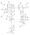
- the fundus imaging apparatus 1 includes an OCT optical system 100 (see FIG. 1) that acquires fundus OCT data, a front imaging optical system 200 (see FIGS. 2 and 3) that captures a front image of the fundus, Is included.
- the two optical systems share the objective optical system.
- the OCT optical system 100 has, for example, a spectral domain type OCT (SD-OCT) as a basic configuration.
- the front photographing optical system is an SLO (Scanning Laser Optoscope) (SLO) optical system.
- the front photographing optical system 200 also serves as a fixation optical system.
- the fundus imaging apparatus 1 also includes an arithmetic controller (arithmetic controller) 70.
- the fundus imaging apparatus 1 may be provided with a memory 72, a monitor 75, an operation unit 80, and the like.
- the arithmetic controller (hereinafter, control unit) 70 is connected to the OCT light source 102, the OCT optical system 100, the laser light source 201, the front imaging optical system 200, and the like.
- the operation unit 80 may be a touch panel, a mouse, a keyboard, or the like.
- the operation unit 75 may be a separate device from the fundus imaging apparatus 1.
- the control unit 70 may control each unit based on an operation signal output from the operation unit 80. For example, an operation for selecting a shooting mode, an operation for release, or the like may be input to the operation unit 80.
- the OCT optical system 100 guides measurement light to the eye E by the light guide optical system 130.
- the OCT optical system 100 guides reference light to the reference optical system 140.
- the OCT optical system 100 causes the detector (light receiving element) 120 to receive the interference signal light acquired by the interference between the measurement light reflected by the eye E and the reference light.
- the OCT optical system 100 is mounted in a housing (device main body) (not shown), and the housing is three-dimensionally moved with respect to the eye E by a known alignment moving mechanism via an operation member such as a joystick. The alignment with respect to the eye to be examined may be performed.
- the OCT optical system 100 uses the SD-OCT method.
- the OCT light source 102 one that emits a light beam having a low coherent length is used, and as the detector 120, a spectral detector that spectrally detects a spectral interference signal for each wavelength component is used.
- the coupler (splitter) 104 is used as a first light splitter, and splits the light emitted from the OCT light source 102 into a measurement optical path and a reference optical path.
- the coupler 110 guides light from the OCT light source 102 to the optical fiber 112 on the measurement optical path side and guides it to the reference optical system 140 on the reference optical path side.
- the light guide optical system 130 is provided to guide the measurement light to the eye E.
- an optical fiber 112 for example, an optical fiber 112, a collimator lens 131, a variable beam expander 132, an optical scanner 134, and an objective lens 320 may be sequentially provided.
- the measurement light is emitted from the emission end of the optical fiber 112 and is converted into a parallel beam by the collimator lens 131.
- the light beam is directed to the optical scanner 134 via the focusing lens 133 in a state where the desired beam diameter is obtained by the variable beam expander 132.
- the light that has passed through the optical scanner 134 is irradiated to the eye E through the objective lens 320.
- a first turning point P 1 is formed at a position conjugate with the optical scanner 134 with respect to the objective lens 320. Since the anterior segment is located at the turning point P1, the measurement light reaches the fundus without vignetting. Further, the measurement light is scanned on the fundus according to the operation of the optical scanner 134. At this time, the measurement light is scattered and reflected by the tissue of the fundus.
- the optical scanner 134 may scan the measurement light on the eye E in the XY direction (transverse direction).
- the optical scanner 134 is, for example, two galvanometer mirrors, and the reflection angle thereof is arbitrarily adjusted by a driving mechanism.
- the light beam emitted from the OCT light source 102 has its reflection (advance) direction changed, and is scanned in an arbitrary direction on the fundus.
- an acousto-optic device (AOM) that changes the traveling (deflection) direction of light may be used in addition to a reflection mirror (galvano mirror, polygon mirror, resonant scanner).
- the scattered light (reflected light) from the eye E due to the measurement light travels back through the path at the time of projection and enters the optical fiber 112 and reaches the coupler 110.
- the coupler 110 guides the light from the optical fiber 112 to the optical path toward the detector 120.
- the attachment optical system 330 is inserted and removed between the objective lens 320 in the light guide optical system 130 and the eye E to be examined.
- a lens attachment including the attachment optical system 330 is attached to and detached from (inserted / removed from) a housing surface (not shown), so that the attachment optical system 330 is inserted / removed between the objective lens 320 on the apparatus main body side and the eye E to be examined. Done.
- the attachment optical system 330 may include a plurality of lenses 331 and 332.
- the second turning point P2 is formed at a position conjugate with the optical scanner 134 with respect to the attachment optical system 330 and the objective optical system 158 by bending at least the lens 164 toward the optical axis L of the measurement light that has passed through the first turning point P1. Is done. That is, the attachment optical system 330 is an optical system that relays the turning point P1 to the turning point P2.
- the turning amount of the measurement light at the second turning point P2 is larger than the turning amount at the first turning point P1.
- the solid angle at the second turning point P2 is increased by a factor of two or more with respect to the solid angle at the first turning point P1.
- scanning is possible in a range of about 60 ° in the retracted state (first mode), and scanning is possible in a range of about 100 ° in the inserted state (second mode).
- the variable beam expander 132 is a light beam diameter adjusting unit in the embodiment.
- the variable beam expander 132 may include a plurality of lenses that form a bilateral telecentric optical system, and the light beam diameter may be switched by changing the lens interval by an actuator.
- the variable beam expander 132 adjusts the beam diameter of the measurement light based on an instruction from the control unit 70.
- the control unit 70 drives the variable beam expander 132 in accordance with the insertion / removal of the attachment optical system, and reduces the light beam diameter in the inserted state relative to the retracted state.
- the ratio of the light beam diameter in the inserted state and the retracted state (the light beam diameter in the variable beam expander 132) is an inverse ratio of the angle of view in the inserted state and the retracted state, so that the resolving power based on the insertion / removal of the attachment optical system 330 is achieved. Can be suppressed.
- the reference optical system 140 generates reference light to be combined with fundus reflection light of measurement light.
- the reference light that has passed through the reference optical system 140 is combined with light from the measurement optical path by the coupler 149 and interferes therewith.
- the reference optical system 140 may be a Michelson type or a Mach-Zehnder type.
- the reference optical system 140 shown in FIG. 1 is formed by a transmission optical system.
- the reference optical system 140 guides the light from the coupler 110 to the detector 120 by transmitting the light without returning.
- the reference optical system 140 may be formed of a reflection optical system, and may be guided to the detector 120 by reflecting light from the coupler 110 by the reflection optical system.
- the reference optical system 140 may be provided with a plurality of reference light paths.
- the optical path that passes through the fiber 142 (the first branch optical path in the present embodiment) and the optical path that passes through the fiber 143 (the second branch optical path in the present embodiment) are separated by the coupler 141. Branch off.
- the fiber 142 and the fiber 143 are connected to the coupler 145, whereby the two branched optical paths are combined and enter the coupler 149 via the reference optical path adjustment unit 147 and the polarization adjustment unit 148.
- the reference light from the coupler 110 is simultaneously guided to the fiber 142 and the fiber 143 by the coupler 141.
- Light that has passed through either the fiber 142 or the fiber 143 is combined with measurement light (fundus reflected light) in the coupler 149.
- the optical path length difference between the fiber 142 and the fiber 143 may be a fixed value.
- the optical path length difference is substantially the same as the optical path length of the attachment optical system 330.
- At least one of the measurement optical path and the reference optical path may be provided with a reference optical path adjustment unit 147 for adjusting the optical path length difference between the measurement light and the reference light.
- the adjustment range of the optical path length in the reference optical path adjustment unit 147 is sufficiently shorter than the optical path length difference between the fiber 142 and the fiber 143 (in other words, the optical path length difference between the first branch optical path and the second branch optical path). It is preferably set.
- the detector 120 is provided to detect interference caused by light from the measurement optical path and light from the reference optical path.
- the detector 120 is a spectroscopic detector, and includes, for example, a spectroscope and a line sensor, and the measurement light and the reference light combined by the coupler 149 are spectrally separated by the spectroscope, Light is received by different regions (pixels) of the line sensor for each wavelength. As a result, an output for each pixel is acquired as a spectrum interference signal.
- the curvature of the fundus and the imaging plane of the measurement light do not necessarily coincide with each other, and in the insertion state of the attachment optical system 150, the difference between the two increases at least in one of the fundus center and the fundus periphery. In the vessel, it is preferable that a sufficient depth range is secured in consideration of the deviation.
- the control unit 70 processes (Fourier analysis) the spectrum interference signal detected by the detector 120 to obtain OCT data of the eye to be examined.
- the arithmetic controller may obtain OCT data in the depth (Z) region by Fourier-transforming the spectrum interference signal in the wave number k space.
- the information after the Fourier transform may be expressed as a signal including a real component and an imaginary component in the Z space.
- the control unit 70 may obtain OCT data by obtaining absolute values of real and imaginary components in the signal in the Z space.
- the reference light passing through the first branch optical path and the reference light passing through the second branch optical path are simultaneously guided to the coupler 149, and each is combined with the measurement light. Since there is a large optical path length difference between the first branch optical path and the second branch optical path, which is about the same as the optical path length of the attachment optical system 330, the reference light passing through the first branch optical path, Of the reference light that has passed through the second branch optical path, one is likely to interfere with the measurement light, while the other is less likely to cause interference.
- the spectral interference signal from the detector 120 includes a component due to the reference light passing through the first branch optical path and a component due to the reference light passing through the second branch optical path.
- One according to the state of the light guide optical system 130 is obtained as a significantly stronger signal than the other. As a result, good OCT data can be obtained regardless of the state of the light guide optical system 130. That is, by having a plurality of reference optical paths having optical path length differences corresponding to the attachment optical system 330, the OCT apparatus according to the embodiment is an amount of change in the optical path length difference between the measurement optical path and the reference optical path, and the attachment The amount of change associated with the insertion / removal of the optical system 330 is compensated regardless of the state of the light guide optical system 130.
- the reference optical path adjustment unit 147 may be controlled to further adjust the optical path length difference between the measurement optical path and the reference optical path, which is the optical axis length of the eye E of the eye E to be examined.
- the fundus reflected light of the measurement light from the fundus peripheral part becomes weaker than the light reflected from the fundus central part, so that the zero delay position between the measurement light path and the reference light path is at the fundus peripheral part.
- the optical path length difference between the measurement optical path and the reference optical path may be adjusted by the reference optical path adjustment unit 147 so as to overlap the intended fundus tissue (for example, the retina, choroid, sclera, etc.).
- the fiber 143 is connected to an attenuator 143a (attenuator).
- the attenuator 143a is arranged to adjust the light quantity balance between the measurement light and the reference light in the inserted state and the retracted state of the attachment optical system 330.
- the attenuation factor of the attenuator may be constant.
- the attenuator may be arranged at a place other than the branch optical path in the reference optical system.
- the attenuation rate in the attenuator may be variable, and the attenuation rate may be switched by the control unit 70 between the inserted state and the retracted state of the attachment optical system 330.
- the detector 120 can change the interval between the grading element 121 (for example, a diffraction grating, a grading lens, etc.) and the line sensor 122, and by changing the interval, the light (here) Then, the irradiation range of the light obtained by combining the measurement light and the reference light may be increased or decreased. Thereby, the resolution in the depth direction can be switched. For example, the irradiation range in the line sensor 122 may be increased in the insertion state with respect to the retracted state. Thereby, OCT data at each position of the fundus can be acquired well even in the inserted state.
- the grading element 121 for example, a diffraction grating, a grading lens, etc.
- the difference in the dispersion amount of the optical system between the measurement optical path and the reference light is corrected in signal processing.
- the correction value stored in advance in the memory is applied in the processing of the spectrum interference signal.
- the first correction value corresponding to the retracted state and the second correction value different from the first correction value and corresponding to the insertion state are stored in the memory 71 in advance, and the light guide optical The correction value to be applied is switched according to the state of the system.
- the OCT apparatus according to the embodiment is the amount of change in the dispersion amount between the measurement optical path and the reference optical path, and the amount of change accompanying the insertion / removal of the attachment optical system 330 is different in each state of the light guide optical system 130. Compensated.
- the amount of dispersion does not necessarily need to be corrected in signal processing, and may be realized by inserting / removing an optical element for dispersion correction with respect to the light receiving / receiving optical path of the measurement light.
- the polarization adjustment unit 148 adjusts the polarization state (here, the polarization state of the reference light). Depending on the state of attachment / detachment (insertion / removal) of the attachment optical system 330, the state of polarization may be switched. For example, the polarization adjustment unit 148 may be driven by a predetermined angle before and after the attachment optical system 330 is attached / detached (inserted / removed) to switch the polarization state.
- the control unit controls a driving unit (driver) (not shown) and displaces the focusing lens 133 according to the angle of view, thereby changing the diopter change of the optical system accompanying attachment / detachment (insertion / detachment) of the attachment optical system 330. It may be corrected.
- a displacement amount of the focusing lens 133 (that is, a diopter correction amount) may be determined based on an observation image acquired via the SLO optical system 200.
- the diopter correction amount may be controlled in conjunction between the OCT optical system 100 and the SLO optical system.
- the SLO optical system 200 acquires a front image of the fundus Er by scanning the laser beam on the fundus Er and receiving the return light of the laser beam from the fundus Er.
- the fundus imaging apparatus 1 scans the fundus image by two-dimensionally scanning the laser light focused on the spot on the observation surface based on the operation of the scanning unit (optical scanner). obtain.
- the SLO optical system 200 may be a so-called line scan type optical system. In this case, a linear light beam is scanned on the observation surface.
- a non-scanning optical system may be used as the front image photographing optical system instead of the scanning optical system as in this embodiment.
- the SLO optical system 200 includes an irradiation optical system 210 and a light receiving optical system 220.
- the optical system when the shooting angle of view is the first angle of view will be described.
- the attachment optical system 330 see FIG. 3
- the shooting angle of view is set to the first angle of view.
- the irradiation optical system 210 includes a scanning unit 216 and an objective optical system 300.
- the objective optical system 300 includes at least one lens.
- the irradiation optical system 210 further includes a laser light source 211, a perforated mirror 213, a lens 214 (a part of the diopter correction unit 240 in the present embodiment), and a lens 215. .
- the laser light source 211 is a light source of the irradiation optical system 210.
- laser light from the laser light source 211 is used as photographing light.
- the laser light source 211 of the present embodiment can emit light of a plurality of colors simultaneously or selectively.
- the laser light source 211 emits light of a total of four colors, three colors in the visible range of blue, green, and red and one color in the infrared range. The light of each color may be emitted simultaneously in any combination.
- the light of each color emitted from the laser light source 211 is used for photographing the fundus.
- a fundus image captured based on fundus reflection light may be referred to as a reflection image
- a fundus image captured based on fluorescence from a fluorescent substance present in the fundus Er may be referred to as a fluorescence image.
- any or all of an infrared image, a color image, a red free image, a monochromatic visible image, and the like may be taken.
- the fluorescence image any or all of the contrast fluorescence image and the spontaneous fluorescence image may be taken.
- the contrast fluorescent image may be an image by fluorescence emission of a contrast agent intravenously injected into the fundus Er, for example, an FA image (fluorescein contrast-enhanced image) or an ICGA image (indocyanine green contrast-enhanced image). Image).
- the spontaneous fluorescence image may be an image obtained by fluorescence emission of a fluorescent substance accumulated in the fundus Er, for example, an image obtained by fluorescence emission of lipofuscin.
- the laser light from the laser light source 211 passes through the opening formed in the perforated mirror 213, passes through the lens 214 and the lens 215, and then travels toward the scanning unit 216.
- the laser light reflected by the scanning unit 216 passes through the dichroic mirror 530 and the dichroic mirror 310, passes through the objective optical system 300, and is then irradiated on the fundus Er of the eye E to be examined.
- the laser light is reflected and scattered by the fundus oculi Er, or excites a fluorescent substance existing in the fundus oculi Er to generate fluorescence from the fundus oculi.
- These lights that is, reflected / scattered light, fluorescence, etc.
- the scanning unit 216 (also referred to as “optical scanner”) is a unit for scanning the laser light emitted from the laser light source 211 on the fundus Er.
- the scanning unit 216 includes two optical scanners having different scanning directions of laser light. That is, an optical scanner 216a for main scanning (for example, scanning in the X direction) and an optical scanner 216b for sub-scanning (for example, scanning in the Y direction) are included.
- the optical scanner 216a for main scanning is a resonant scanner and the optical scanner 2216b for sub scanning is a galvanometer mirror.
- other optical scanners may be applied to each of the optical scanners 216a and 216b.
- an acousto-optic device that changes the light traveling (deflection) direction, etc. May be applied.
- the objective optical system 300 is the objective optical system of the fundus imaging apparatus 1.
- the objective optical system 300 is used to irradiate the eye E with the laser beam scanned by the scanning unit 216 and guide it to the fundus Er.
- the objective optical system 300 forms a turning point P around which the laser light passed through the scanning unit 216 is turned.
- the turning point P is formed on the reference optical axis L1 of the irradiation optical system 210 and at a position optically conjugate with the scanning unit 216 with respect to the objective optical system 300.
- conjuggate is not necessarily limited to a complete conjugate relationship, and includes “substantially conjugate”.
- the objective optical system 300 of the fundus photographing apparatus 1 is realized only by a lens, but is not necessarily limited to this, and may be realized by a combination of a lens and a mirror.
- the laser light that has passed through the scanning unit 216 passes through the objective optical system 300 and is irradiated on the fundus Er through the turning point P. For this reason, the laser light that has passed through the objective optical system 300 is turned around the turning point P as the scanning unit 216 operates. As a result, in the present embodiment, the laser beam is scanned two-dimensionally on the fundus Er.
- the laser light applied to the fundus Er is condensed at a condensing position (for example, the retina surface).
- the light receiving optical system 220 has one or more light receiving elements.
- the light receiving optical system 220 may include a plurality of light receiving elements 225, 227, and 229.
- the light receiving optical system 220 may include a plurality of light receiving elements 225, 227, and 229.
- light from the fundus Er by the laser light emitted by the irradiation optical system 210 is received by at least one of the light receiving elements 225, 227, and 229.
- the light receiving optical system 220 in the present embodiment may share each member arranged from the objective optical system 300 to the perforated mirror 213 with the irradiation optical system 210.
- light from the fundus Er is guided back to the perforated mirror 213 along the optical path of the irradiation optical system 210.
- the perforated mirror 213 removes light from the fundus Er while removing at least part of noise light due to reflection on the cornea of the eye E and the optical system inside the apparatus (for example, the lens surface of the objective lens system).
- the light is guided to an independent optical path of the light receiving optical system 220.
- the optical path branching member that branches the irradiation optical system 210 and the light receiving optical system 220 is not limited to the perforated mirror 213, and other optical members (for example, a half mirror) may be used.
- the light receiving optical system 220 of the present embodiment includes a lens 221, a pinhole plate 223, and a light separation unit (light separation unit) 230 in the reflected light path of the perforated mirror 213.
- the pinhole plate 223 is disposed on the fundus conjugate plane and functions as a confocal stop in the fundus photographing apparatus 1. That is, when the diopter is appropriately corrected by the diopter correction unit 240, the light from the fundus Er that has passed through the lens 221 is focused at the opening of the pinhole plate 223.
- the pinhole plate 223 removes light from a position other than the condensing point (or focal plane) of the fundus Er, and the rest (light from the condensing point) is directed to at least one of the light receiving elements 225, 227, and 229. Led.
- the light separation unit 230 separates light from the fundus Er.
- light from the fundus Er is wavelength-separated by the light separation unit 230 in a wavelength selective manner.
- the light separation unit 230 may also serve as a light branching unit that branches the optical path of the light receiving optical system 220.
- the light separation unit 230 may include two dichroic mirrors (dichroic filters) 231 and 232 having different light separation characteristics (wavelength separation characteristics).
- the optical path of the light receiving optical system 220 is branched into three by two dichroic mirrors 231 and 232.
- one of the light receiving elements 225, 227, and 229 is arranged at the tip of each branch optical path.
- the light separation unit 230 separates the wavelength of the light from the fundus Er and causes the three light receiving elements 225, 227, and 229 to receive light in different wavelength ranges.
- the light receiving elements 225, 227, and 229 may receive light of three colors of blue, green, and red one by one. In this case, a color image may be acquired from the light reception results of the light receiving elements 225, 227, and 229.
- the light separation unit 230 may cause the fundus autofluorescence and the infrared light that is the fundus reflection light of the observation light to be received by different light receiving elements. Thereby, an infrared image may be captured simultaneously with the fluorescent image.
- blue light emitted from the laser light source 211 is used as excitation light of spontaneous fluorescence.
- the control unit 70 forms a fundus image based on the light reception signals output from the light receiving elements 225, 227, and 229, for example. More specifically, the control unit 70 forms a fundus image in synchronization with the optical scanning performed by the scanning unit 216. For example, each time the sub-scanning optical scanner 216b reciprocates n times (n is an integer equal to or greater than 1), the control unit 70 displays the fundus image of at least one frame (in other words, one sheet) (the light receiving element). Every time). In the following, for the sake of convenience, it is assumed that one frame of the fundus image is formed for each reciprocation of the optical scanner 216b for sub-scanning unless otherwise specified.
- the control unit 70 uses a maximum of three types of images based on signals from the respective light receiving elements 225, 227, and 229 for sub-scanning. It is generated every time the optical scanner 216b makes one reciprocation.
- the control unit 70 may cause the monitor 75 to display a plurality of frames of fundus images sequentially formed based on the operation of the apparatus as described above as an observation image in time series.
- the observation image is a moving image composed of a fundus image acquired in substantially real time.
- the control unit 70 captures (captures) a part of a plurality of fundus images that are sequentially formed as a captured image (capture image).
- the captured image is stored in a storage medium.
- the storage medium for storing the captured image may be a non-volatile storage medium (for example, a hard disk, a flash memory, etc.).
- a fundus image formed at a predetermined timing (or period) is captured after outputting a trigger signal (for example, a release operation signal or the like).
- the alignment optical system 500 of this embodiment includes a dichroic mirror 530, an alignment light source 520, and a light receiving element 510 as an example.
- the alignment optical system 500 may include a lens 540 as an optical element for correcting the magnification of the alignment index.
- Alignment light emitted from the alignment light source 520 is reflected by the dichroic mirror 530 and irradiated toward the eye E through the objective optical system.
- the alignment light reflected by the cornea of the eye E is reflected by the dichroic mirror 530 through the objective optical system and received by the light receiving element 510 via the lens 540.
- the light receiving element 510 detects the alignment state of the eye E with respect to the objective optical system based on the light reception result.
- the signal output from the light receiving element 510 is input to the control unit 70 (see FIG. 4).
- the control unit 70 may generate an image indicating the alignment state of the eye E (hereinafter also referred to as “alignment image”) based on the input signal.
- the alignment image may be, for example, an image including an alignment index image indicating alignment light reflected by the cornea of the eye E.
- the lens 540 is movable along the optical axis, thereby changing the focal length of the alignment optical system and switching the magnification of the alignment index image.
- the fundus imaging apparatus 1 may be provided with a drive unit 540a that moves the lens 540.
- the lens 540 is displaced according to the attachment / detachment (insertion / removal) of the attachment optical system 330 (that is, according to the view angle switching).
- an anterior ocular segment observation system that images the anterior ocular segment of the eye to be examined may be used.
- the attachment optical system 330 is disposed between the objective optical system 300 and the eye E, so that the objective optical system 18 for photographing at the second angle of view is configured.
- the attachment optical system 330 of this embodiment has at least one lens. As shown in FIG. 3, the attachment optical system 330 may have a plurality of lenses.
- the attachment optical system 330 When the attachment optical system 330 is attached, the shooting angle of view is increased, but on the other hand, the magnification is reduced. Therefore, before and after the attachment optical system 330 is attached / detached (inserted / removed), the lens 540, the light receiving element 510, Is maintained, the alignment index image photographed by the light receiving element 510 is reduced. In this embodiment, the lens 540 is displaced, and the distance between the focal point of the corneal reflected light of the index light beam and the imaging surface of the light receiving element 510 is switched.
- the control unit 70 when the attachment optical system 330 is not attached (that is, when the angle of view is the first angle of view), the control unit 70 is the distance between the focal point of the corneal reflected light of the index light beam and the imaging surface of the light receiving element 510. Is set to the first distance.
- the control unit 70 sets the distance between the focal point of the corneal reflected light of the index light beam and the imaging surface of the light receiving element 510. Set to a second distance that is more than one distance away.
- control unit 70 may switch the unit displacement amount (adjustment pitch) of the lens 214 (optical element in the diopter correction unit) before and after the attachment optical system 330 is attached / detached (inserted / removed). More specifically, the adjustment pitch may be increased in the inserted state with respect to the retracted state (not mounted). Thereby, the time required for diopter correction is easily shortened.
- control unit 70 may switch the position of the lens 214 before and after the attachment optical system 330 is attached / detached (inserted / removed). Thereby, you may correct
- control unit 70 is a detection region for detecting the diopter correction state of the SLO optical system 200 before and after the attachment optical system 330 is attached / detached (insertion / removal).
- the diopter correction state is detected based on the contrast of the entire observation image, and in the insertion state, the central portion of the observation image (here, the angle corresponding to 60 ° is the same as that of the observation image in the retracted state).
- the diopter correction state is detected based on the contrast of the region.
- the diopter may be adjusted so that the contrast of the detection region is maximized in each state.
- the diopter correction state with respect to the range of the angle of view of 60 ° matches in both the insertion state and the retracted state. Therefore, the fundus image captured between the inserted state and the retracted state is obtained. It is advantageous in associating and comparing.
- the examiner attaches and detaches the attachment optical system 330 to the fundus photographing apparatus 1 and sets the photographing field angle of the fundus photographing apparatus 1.
- the attachment / detachment (insertion / removal) state of the attachment optical system 330 may be manually input to the fundus imaging apparatus 1 by the examiner.
- a sensor for detecting the attachment / detachment (insertion / removal) state of the attachment optical system 330 may be provided in the fundus photographing apparatus 1, and a detection signal from the sensor may be input to the fundus photographing apparatus 1.
- the light amount, the gain, the diopter correction amount, the light amount balance between the measurement light and the reference light, the resolution in the depth direction, the peripheral portion and the central portion may be performed.
- various types of switching may be performed on the light amount, gain, diopter correction amount, aperture opening, and the like.
- the control unit 70 may display a widget for selecting a photographing method on the monitor 75 according to the attachment / detachment (insertion / removal) state of the attachment optical system 330 (see FIG. 8).
- a widget for selecting a photographing method on the monitor 75 according to the attachment / detachment (insertion / removal) state of the attachment optical system 330 (see FIG. 8).
- color imaging, FA imaging, ICGA imaging, spontaneous fluorescence imaging, and OCT imaging may be selectable as the imaging method.
- widgets (buttons in FIG. 8) for selecting these imaging methods may be displayed on the monitor 75.
- the spontaneous fluorescence photographing cannot be selected, and color photographing, FA photographing, ICGA photographing, OCT photographing may be selectable.
- the widget for selecting the spontaneous fluorescence imaging may be hidden, and only the widget for selecting the remaining imaging methods may be displayed on the monitor 75.
- the autofluorescence imaging in the insertion state which is difficult to capture with appropriate signal efficiency, is not selectable along with the non-display of the widget, so an image with low clinical significance is captured. Can be suppressed.
- control unit 70 may start obtaining and displaying the observation image.
- the examiner confirms the photographing position on the observation image and performs the release operation. Thereby, an image of the fundus is captured by a previously selected photographing method.
Landscapes
- Health & Medical Sciences (AREA)
- Life Sciences & Earth Sciences (AREA)
- Medical Informatics (AREA)
- Biophysics (AREA)
- Ophthalmology & Optometry (AREA)
- Engineering & Computer Science (AREA)
- Biomedical Technology (AREA)
- Heart & Thoracic Surgery (AREA)
- Physics & Mathematics (AREA)
- Molecular Biology (AREA)
- Surgery (AREA)
- Animal Behavior & Ethology (AREA)
- General Health & Medical Sciences (AREA)
- Public Health (AREA)
- Veterinary Medicine (AREA)
- Nuclear Medicine, Radiotherapy & Molecular Imaging (AREA)
- Radiology & Medical Imaging (AREA)
- Eye Examination Apparatus (AREA)
Priority Applications (2)
| Application Number | Priority Date | Filing Date | Title |
|---|---|---|---|
| JP2020504963A JP7226426B2 (ja) | 2018-03-06 | 2019-02-28 | 眼底撮影装置 |
| EP19764141.8A EP3763282B1 (en) | 2018-03-06 | 2019-02-28 | Ocular fundus imaging device |
Applications Claiming Priority (2)
| Application Number | Priority Date | Filing Date | Title |
|---|---|---|---|
| JP2018-039471 | 2018-03-06 | ||
| JP2018039471 | 2018-03-06 |
Publications (1)
| Publication Number | Publication Date |
|---|---|
| WO2019172062A1 true WO2019172062A1 (ja) | 2019-09-12 |
Family
ID=67846114
Family Applications (1)
| Application Number | Title | Priority Date | Filing Date |
|---|---|---|---|
| PCT/JP2019/007760 Ceased WO2019172062A1 (ja) | 2018-03-06 | 2019-02-28 | 眼底撮影装置 |
Country Status (3)
| Country | Link |
|---|---|
| EP (1) | EP3763282B1 (https=) |
| JP (1) | JP7226426B2 (https=) |
| WO (1) | WO2019172062A1 (https=) |
Cited By (7)
| Publication number | Priority date | Publication date | Assignee | Title |
|---|---|---|---|---|
| CN112617743A (zh) * | 2019-10-07 | 2021-04-09 | 奥普托斯股份有限公司 | 眼科扫描系统和方法 |
| CN113327202A (zh) * | 2021-03-30 | 2021-08-31 | 苏州微清医疗器械有限公司 | 一种图像畸变的矫正方法及其应用 |
| CN114271782A (zh) * | 2021-11-30 | 2022-04-05 | 视微影像(河南)科技有限公司 | 一种可切换成广角/超广角的眼底成像目镜 |
| CN115153422A (zh) * | 2022-05-30 | 2022-10-11 | 清华大学 | 基于元成像的眼底成像方法及系统 |
| JP2023074081A (ja) * | 2021-11-17 | 2023-05-29 | 株式会社トーメーコーポレーション | Sd-oct装置 |
| CN116548910A (zh) * | 2023-05-19 | 2023-08-08 | 北京至真互联网技术有限公司 | 一种眼科相干断层扫描仪的分辨率自适应调节方法及系统 |
| US20250152002A1 (en) * | 2023-11-13 | 2025-05-15 | Optopol Technology Sp. Z O.O. | Device for measuring the characteristics of the human eye using oct technology |
Citations (5)
| Publication number | Priority date | Publication date | Assignee | Title |
|---|---|---|---|---|
| JP2015091309A (ja) * | 2013-09-30 | 2015-05-14 | 株式会社ニデック | 眼科用画像処理装置および画像処理プログラム |
| JP2016123467A (ja) | 2014-12-26 | 2016-07-11 | 株式会社ニデック | 眼底撮影装置および広角レンズアタッチメント |
| JP2017189219A (ja) * | 2016-04-11 | 2017-10-19 | 株式会社トプコン | 眼科撮影装置 |
| JP2017196210A (ja) * | 2016-04-28 | 2017-11-02 | 株式会社トプコン | 眼科撮影装置 |
| JP2017225599A (ja) * | 2016-06-22 | 2017-12-28 | 株式会社トプコン | Oct装置 |
Family Cites Families (1)
| Publication number | Priority date | Publication date | Assignee | Title |
|---|---|---|---|---|
| JP6552200B2 (ja) * | 2015-01-09 | 2019-07-31 | キヤノン株式会社 | 光断層撮像装置、その制御方法、及びプログラム |
-
2019
- 2019-02-28 EP EP19764141.8A patent/EP3763282B1/en active Active
- 2019-02-28 JP JP2020504963A patent/JP7226426B2/ja active Active
- 2019-02-28 WO PCT/JP2019/007760 patent/WO2019172062A1/ja not_active Ceased
Patent Citations (5)
| Publication number | Priority date | Publication date | Assignee | Title |
|---|---|---|---|---|
| JP2015091309A (ja) * | 2013-09-30 | 2015-05-14 | 株式会社ニデック | 眼科用画像処理装置および画像処理プログラム |
| JP2016123467A (ja) | 2014-12-26 | 2016-07-11 | 株式会社ニデック | 眼底撮影装置および広角レンズアタッチメント |
| JP2017189219A (ja) * | 2016-04-11 | 2017-10-19 | 株式会社トプコン | 眼科撮影装置 |
| JP2017196210A (ja) * | 2016-04-28 | 2017-11-02 | 株式会社トプコン | 眼科撮影装置 |
| JP2017225599A (ja) * | 2016-06-22 | 2017-12-28 | 株式会社トプコン | Oct装置 |
Non-Patent Citations (1)
| Title |
|---|
| See also references of EP3763282A4 |
Cited By (9)
| Publication number | Priority date | Publication date | Assignee | Title |
|---|---|---|---|---|
| CN112617743A (zh) * | 2019-10-07 | 2021-04-09 | 奥普托斯股份有限公司 | 眼科扫描系统和方法 |
| CN113327202A (zh) * | 2021-03-30 | 2021-08-31 | 苏州微清医疗器械有限公司 | 一种图像畸变的矫正方法及其应用 |
| JP2023074081A (ja) * | 2021-11-17 | 2023-05-29 | 株式会社トーメーコーポレーション | Sd-oct装置 |
| JP7795190B2 (ja) | 2021-11-17 | 2026-01-07 | 株式会社トーメーコーポレーション | Sd-oct装置 |
| CN114271782A (zh) * | 2021-11-30 | 2022-04-05 | 视微影像(河南)科技有限公司 | 一种可切换成广角/超广角的眼底成像目镜 |
| CN115153422A (zh) * | 2022-05-30 | 2022-10-11 | 清华大学 | 基于元成像的眼底成像方法及系统 |
| CN116548910A (zh) * | 2023-05-19 | 2023-08-08 | 北京至真互联网技术有限公司 | 一种眼科相干断层扫描仪的分辨率自适应调节方法及系统 |
| CN116548910B (zh) * | 2023-05-19 | 2023-12-08 | 北京至真互联网技术有限公司 | 一种眼科相干断层扫描仪的分辨率自适应调节方法及系统 |
| US20250152002A1 (en) * | 2023-11-13 | 2025-05-15 | Optopol Technology Sp. Z O.O. | Device for measuring the characteristics of the human eye using oct technology |
Also Published As
| Publication number | Publication date |
|---|---|
| EP3763282B1 (en) | 2025-10-29 |
| JPWO2019172062A1 (ja) | 2021-02-18 |
| EP3763282A1 (en) | 2021-01-13 |
| EP3763282A4 (en) | 2021-11-24 |
| JP7226426B2 (ja) | 2023-02-21 |
Similar Documents
| Publication | Publication Date | Title |
|---|---|---|
| JP5511437B2 (ja) | 光断層像撮影装置 | |
| JP4819478B2 (ja) | 眼科撮影装置 | |
| EP2130486B1 (en) | Ophthalmic Photographing Apparatus | |
| JP7226426B2 (ja) | 眼底撮影装置 | |
| JP6049309B2 (ja) | 測定装置、眼科撮影装置、制御方法及びプログラム | |
| JP6049310B2 (ja) | 撮影装置、制御方法及びプログラム | |
| US9848767B2 (en) | Ophthalmological apparatus | |
| WO2014054394A1 (ja) | 眼科観察装置 | |
| JP5179265B2 (ja) | 眼科撮影装置 | |
| JP6776076B2 (ja) | Oct装置 | |
| JP4949504B2 (ja) | 眼科撮影装置 | |
| JP5807371B2 (ja) | 眼科撮影装置 | |
| JP5255711B2 (ja) | 眼科撮影装置 | |
| JP6279682B2 (ja) | 眼科観察装置 | |
| JP7098964B2 (ja) | 眼底撮影装置 | |
| JP7056242B2 (ja) | 眼底撮影装置 | |
| JP6957842B2 (ja) | 眼底撮影装置 | |
| JP2019063243A (ja) | 眼科撮影装置 | |
| JP6848207B2 (ja) | 眼科撮影装置 | |
| JP6431399B2 (ja) | 眼科撮影装置 | |
| JP7635553B2 (ja) | 眼科撮影装置 | |
| JP2020044452A (ja) | 眼科装置 | |
| JP2015195874A (ja) | 眼底撮影装置 | |
| JP6057060B2 (ja) | 眼底撮影装置 | |
| JP5306554B2 (ja) | 眼科撮影装置 |
Legal Events
| Date | Code | Title | Description |
|---|---|---|---|
| 121 | Ep: the epo has been informed by wipo that ep was designated in this application |
Ref document number: 19764141 Country of ref document: EP Kind code of ref document: A1 |
|
| ENP | Entry into the national phase |
Ref document number: 2020504963 Country of ref document: JP Kind code of ref document: A |
|
| NENP | Non-entry into the national phase |
Ref country code: DE |
|
| ENP | Entry into the national phase |
Ref document number: 2019764141 Country of ref document: EP Effective date: 20201006 |
|
| WWG | Wipo information: grant in national office |
Ref document number: 2019764141 Country of ref document: EP |