WO2019167692A1 - 金型装置 - Google Patents
金型装置 Download PDFInfo
- Publication number
- WO2019167692A1 WO2019167692A1 PCT/JP2019/005799 JP2019005799W WO2019167692A1 WO 2019167692 A1 WO2019167692 A1 WO 2019167692A1 JP 2019005799 W JP2019005799 W JP 2019005799W WO 2019167692 A1 WO2019167692 A1 WO 2019167692A1
- Authority
- WO
- WIPO (PCT)
- Prior art keywords
- mold
- surface layer
- cavity
- mold apparatus
- base
- Prior art date
- Legal status (The legal status is an assumption and is not a legal conclusion. Google has not performed a legal analysis and makes no representation as to the accuracy of the status listed.)
- Ceased
Links
Images


Classifications
-
- B—PERFORMING OPERATIONS; TRANSPORTING
- B22—CASTING; POWDER METALLURGY
- B22D—CASTING OF METALS; CASTING OF OTHER SUBSTANCES BY THE SAME PROCESSES OR DEVICES
- B22D17/00—Pressure die casting or injection die casting, i.e. casting in which the metal is forced into a mould under high pressure
- B22D17/20—Accessories: Details
- B22D17/22—Dies; Die plates; Die supports; Cooling equipment for dies; Accessories for loosening and ejecting castings from dies
- B22D17/2209—Selection of die materials
-
- B—PERFORMING OPERATIONS; TRANSPORTING
- B22—CASTING; POWDER METALLURGY
- B22D—CASTING OF METALS; CASTING OF OTHER SUBSTANCES BY THE SAME PROCESSES OR DEVICES
- B22D17/00—Pressure die casting or injection die casting, i.e. casting in which the metal is forced into a mould under high pressure
- B22D17/20—Accessories: Details
-
- B—PERFORMING OPERATIONS; TRANSPORTING
- B22—CASTING; POWDER METALLURGY
- B22C—FOUNDRY MOULDING
- B22C3/00—Selection of compositions for coating the surfaces of moulds, cores, or patterns
-
- B—PERFORMING OPERATIONS; TRANSPORTING
- B22—CASTING; POWDER METALLURGY
- B22C—FOUNDRY MOULDING
- B22C9/00—Moulds or cores; Moulding processes
- B22C9/06—Permanent moulds for shaped castings
-
- B—PERFORMING OPERATIONS; TRANSPORTING
- B22—CASTING; POWDER METALLURGY
- B22C—FOUNDRY MOULDING
- B22C9/00—Moulds or cores; Moulding processes
- B22C9/06—Permanent moulds for shaped castings
- B22C9/061—Materials which make up the mould
-
- B—PERFORMING OPERATIONS; TRANSPORTING
- B22—CASTING; POWDER METALLURGY
- B22D—CASTING OF METALS; CASTING OF OTHER SUBSTANCES BY THE SAME PROCESSES OR DEVICES
- B22D17/00—Pressure die casting or injection die casting, i.e. casting in which the metal is forced into a mould under high pressure
- B22D17/20—Accessories: Details
- B22D17/22—Dies; Die plates; Die supports; Cooling equipment for dies; Accessories for loosening and ejecting castings from dies
-
- B—PERFORMING OPERATIONS; TRANSPORTING
- B22—CASTING; POWDER METALLURGY
- B22D—CASTING OF METALS; CASTING OF OTHER SUBSTANCES BY THE SAME PROCESSES OR DEVICES
- B22D21/00—Casting non-ferrous metals or metallic compounds so far as their metallurgical properties are of importance for the casting procedure; Selection of compositions therefor
- B22D21/002—Castings of light metals
- B22D21/007—Castings of light metals with low melting point, e.g. Al 659 degrees C, Mg 650 degrees C
-
- B—PERFORMING OPERATIONS; TRANSPORTING
- B22—CASTING; POWDER METALLURGY
- B22D—CASTING OF METALS; CASTING OF OTHER SUBSTANCES BY THE SAME PROCESSES OR DEVICES
- B22D21/00—Casting non-ferrous metals or metallic compounds so far as their metallurgical properties are of importance for the casting procedure; Selection of compositions therefor
- B22D21/02—Casting exceedingly oxidisable non-ferrous metals, e.g. in inert atmosphere
- B22D21/04—Casting aluminium or magnesium
Definitions
- This disclosure relates to a mold apparatus.
- Patent Document 1 discloses that a reducing organic acid or organic acid salt is used at a concentration of 0.01 wt% or more on the surface of a mold that comes into contact with a molten metal and a release agent emulsion as a stock solution concentration.
- the cavity of the mold is filled with molten aluminum.
- nitriding treatment or multilayer coating of a heat-resistant ceramic layer is applied to the surface forming the cavity of the mold as a measure against aluminum adhesion to the mold and melting damage.
- the nitrogen diffusion layer is gradually decomposed by contact with a high-temperature aluminum melt, so that it lacks durability.
- multilayer coating of heat-resistant ceramic layers when the molten aluminum enters the coating starting from film defects, the coated mold base is eroded by reaction with the molten aluminum, and the heat-resistant ceramic layer peels off. There is a fear.
- the present disclosure has been made in view of the above problems, and an object of the present disclosure is to provide a mold apparatus that prevents welding with molten aluminum and prevents damage to the mold.
- the present disclosure is a mold apparatus capable of manufacturing an aluminum die-cast member, and includes a mold and a molten metal supply unit.
- the mold can form a cavity that can be filled with molten aluminum.
- the mold has a base portion made of iron and a surface layer portion which is provided on the cavity side of the base portion and contains 20% by weight or more of chromium and can form a dichromium trioxide film on the surface of the cavity side.
- the molten metal supply unit can supply molten aluminum to the cavity.
- the surface layer portion provided with the cavity side of the base portion in the mold includes 20% by weight or more of chromium.
- chromium As a result, it is possible to form a dichromium trioxide film which is a passive film relatively dense with respect to the molten aluminum and has non-wetting properties and corrosion resistance with respect to the molten aluminum on the surface of the surface layer on the cavity side. Thereby, when the molten aluminum is filled in the cavity, welding between the mold base and the molten aluminum can be reliably prevented.
- the dichromium trioxide film on the surface layer may be peeled off due to the cooling / heating cycle of the mold or sliding when the aluminum die-cast member is removed from the mold.
- the dichromium oxide film is peeled off, chromium moves to the surface of the surface layer portion inside the mold, and a new dichromium trioxide film can be formed.
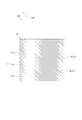
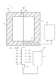
- FIG. 1 is a schematic view of a mold apparatus according to the first embodiment.
- FIG. 2 is an enlarged view of part II in FIG.
- FIG. 3 is a schematic diagram for explaining the operation of the mold apparatus according to the first embodiment.
- FIG. 4 is a schematic diagram illustrating the operation of the mold apparatus according to the first embodiment, and is a schematic diagram illustrating the next state of FIG.
- FIG. 5 is a schematic diagram illustrating the operation of the mold apparatus according to the first embodiment, and is a schematic diagram illustrating the next state of FIG.
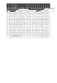
- FIG. 6 is a photograph showing experimental results regarding the mold apparatus according to the first embodiment.
- FIG. 7 is a photograph showing experimental results regarding the mold apparatus of the comparative example
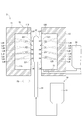
- FIG. 8 is a schematic view of a mold apparatus according to the second embodiment.
- FIG. 9 is a schematic diagram for explaining the operation of the mold apparatus according to the second embodiment.
- a mold apparatus 1 according to a first embodiment will be described with reference to FIGS.
- the mold apparatus 1 is used for die-casting a member 5 (see FIG. 5) as an “aluminum die-cast member” made of aluminum.
- the mold apparatus 1 includes a mold 10 and a molten metal supply unit 20.
- the mold 10 has a movable mold 11 and a fixed mold 12.
- the movable mold 11 and the fixed mold 12 form a cavity 100 that can be filled with molten aluminum.
- the movable mold 11 is made of metal, for example, steel.
- the movable mold 11 is provided so as to be relatively movable with respect to the fixed mold 12 as indicated by an outline arrow F0.
- the movable mold 11 has a first space 110 having an opening on the fixed mold 12 side.
- the first space 110 becomes a part of the cavity 100.
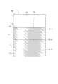
- An enlarged view of the surface of the movable mold 11 on the side in contact with the molten aluminum is shown in FIG.
- the movable mold 11 includes a base part 111, a concentration transition part 112, and a surface layer part 113.
- the base portion 111, the concentration transition portion 112, and the surface layer portion 113 are integrally formed.
- the base 111 is a part forming the skeleton of the movable mold 11. As shown in FIG. 2, the base 111 is provided at a position relatively distant from the first space 110. In the present embodiment, the base 111 is made of iron having a carbon concentration of 0.07% by weight or less.
- the concentration transition part 112 is a part provided on the first space 110 side of the base part 111.
- the concentration transition portion 112 is formed so that the chromium concentration increases in an inclined manner from the base portion 111 toward a surface layer portion 113 described later.
- the boundary between the base portion 111 and the concentration transition portion 112 is indicated by a virtual line VL111.
- the surface layer portion 113 is a portion that is provided on the first space 110 side of the concentration transition portion 112 and is an inner wall that forms the first space 110.
- the surface layer portion 113 is formed to have a thickness of 30 ⁇ m or more and 200 ⁇ m or less.
- the surface layer portion 113 is formed to have a chromium concentration of 20% by weight or more by, for example, chromizing such as a gas phase method or a powder method, a thermal diffusion method of a chromium coating product, or the like.
- a dichromium trioxide (hereinafter referred to as “Cr 2 O 3 ”) film 114 is formed on the first space 110 side of the surface layer portion 113 (see FIG. 3).
- the Cr 2 O 3 film 114 is characterized in that the heat-resistant temperature is 1350 degrees higher than the aluminum casting temperature of 680 degrees and there is no defect.
- the Cr 2 O 3 film 114 is formed to have a thickness of 3 nm or more, for example.
- the scale is changed to make it easy to see that the Cr 2 O 3 film 114 is formed.
- 2 shows a boundary between the concentration transition portion 112 and the surface layer portion 113 by an imaginary line VL112
- FIG. 3 shows a boundary between the Cr 2 O 3 film 114 and other portions in the surface layer portion 113. This is indicated by a virtual line VL113.
- the fixed mold 12 is made of metal, for example, steel.
- the fixed mold 12 is fixed so as not to move, and has a second space 120 having an opening on the movable mold 11 side and a communication hole 121 as shown in FIG.
- the second space 120 becomes a part of the cavity 100. That is, the cavity 100 is constituted by the first space 110 and the second space 120.
- the communication hole 121 communicates the second space 120 and the outside of the fixed mold 12.
- the fixed mold 12 has the same configuration as the movable mold 11, and has a base portion, a concentration transition portion, and a surface layer portion. Each of the base portion, concentration transition portion, and surface layer portion of the fixed mold 12 has the same characteristics as the base portion 111, concentration transition portion 112, and surface layer portion 113 of the movable die 11.
- the base part, concentration transition part, and surface layer part of the fixed mold 12 are integrally formed.
- the molten metal supply unit 20 is formed so that molten aluminum can be supplied to the cavity 100 of the mold 10.
- the molten metal supply unit 20 supplies molten aluminum to the second space 120 through the communication hole 121 of the fixed mold 12.
- FIGS. 3 to 5 show changes in enlarged views in the vicinity of the surface layer portion 113 of the movable mold 11 in the die casting method using the mold apparatus 1.
- the operation of the movable mold 11 will be described, but the same applies to the fixed mold 12.
- a Cr 2 O 3 film 114 is formed on the surface of the surface layer portion 113 of the movable mold 11 and the surface layer portion of the fixed mold 12. Has been.
- the movable mold 11 and the fixed mold 12 are combined to form the cavity 100.
- the molten aluminum 4 is supplied from the molten metal supply unit 20 to the mold 10 in which the cavity 100 is formed.
- the molten aluminum 4 supplied by the molten metal supply unit 20 is press-fitted into the cavity 100 and filled into the cavity 100.
- the molten aluminum 4 press-fitted into the cavity 100 spreads over the surface 115 of the Cr 2 O 3 film 114 opposite to the concentration transition portion 112. That is, the movable mold 11 and the fixed mold 12 are in contact with the molten aluminum by the Cr 2 O 3 film 114.
- the molten aluminum 4 filled in the cavity 100 is solidified to form the member 5.
- the movable mold 11 and the fixed mold 12 are separated by moving the movable mold 11, and the member 5 is taken out from the mold 10.
- the Cr 2 O 3 film 114 is peeled off by the movement of the member 5 as indicated by the white arrow F 1 in FIG.
- a Cr 2 O 3 film 114 is regenerated on the surface of the surface layer portion 113 as shown in FIG.
- the molten aluminum that is press-fitted into the cavity 100 for manufacturing the next member 5 reaches the surface 115 of the regenerated Cr 2 O 3 film 114.
- FIGS. 6 and 7 are cross-sectional photographs of the surface of the mold on the cavity side after the molded member is taken out from the cavity.
- FIG. 6 shows a cross-sectional photograph of the vicinity of the surface of the mold 10 on the cavity 100 side in die casting using the mold apparatus 1.
- the surface of the mold 10 on the cavity 100 side is subjected to chromium infiltration treatment.
- FIG. 7 as a comparative example, in die casting using a mold apparatus that does not have a structure corresponding to the surface layer portion and the concentration transition section of the mold apparatus 1 (hereinafter, referred to as “mold apparatus of comparative example”).
- die is shown.
- the surface of the mold on the cavity side is subjected to nitriding treatment.
- the surface layer portion 113 provided on the cavity 100 side of the base portion 111 in the mold 10 contains 20% by weight or more of chromium.
- chromium a Cr 2 O 3 film which is a relatively dense passive film with respect to the molten aluminum 4 and has non-wetting properties and corrosion resistance with respect to the molten aluminum 4 on the cavity 100 side of the surface layer portion 113. It has become.
- the mold apparatus 1 can reliably prevent the base 111 of the mold 10 and the molten aluminum 4 from being welded.
- the surface of the surface layer portion of the mold 10 is maintained in a relatively flat state as shown in FIG. Thereby, dimensional accuracy can be improved, maintaining the external appearance quality of the member 5 shape
- the metal mold apparatus 1 when the member 5 molded in the cavity 100 is taken out from the mold 10, the Cr 2 O 3 film 114 formed on the surface layer 113 may be peeled off. .
- chromium moves to the surface of the surface layer portion 113 inside the mold 10, and a new Cr 2 O 3 film 114 can be formed.
- the metal mold apparatus 1 by 1st embodiment can prevent welding with the metal mold
- the concentration transition portion 112 is formed so that the chromium concentration increases in a slope from the base portion 111 toward the surface layer portion 113.
- the first embodiment it is possible to prevent the Cr 2 O 3 film 114 by thermal stress easily peeled off from the mold 10.
- the surface layer portion 113 is formed to have a thickness of 30 ⁇ m or more and 200 ⁇ m or less. This is because when the thickness of the surface layer portion 113 is less than 30 ⁇ m, the Cr 2 O 3 film 114 is difficult to be reproduced, and when the thickness of the surface layer portion 113 is greater than 200 ⁇ m, the surface layer portion 113 is hardened and the Cr 2 O 3 film 114 is hardened. It is because it becomes easy to peel from the surface layer part 113. Therefore, in the first embodiment, the Cr 2 O 3 film 114 can be appropriately maintained by setting the thickness of the surface layer portion 113 to 30 ⁇ m or more and 200 ⁇ m or less.
- the base of the movable mold 11 and the fixed mold 12 has a carbon concentration of 0.07% by weight or less. Therefore, it is possible to prevent chromium contained in the concentration transition part on the cavity 100 side of the base from being captured by the carbon of the base. Therefore, in the first embodiment, the chromium concentration in the concentration transition portion and the surface layer portion can be maintained at a desired concentration.
- the mold apparatus 2 includes a mold 10, a molten metal supply unit 20, and an oxidant supply unit 30.
- the oxidant supply unit 30 includes an oxidant tank 31 and a spray nozzle 32.
- the oxidant tank 31 is provided outside the mold 10.
- the oxidant tank 31 stores an oxidizing acid that can react with the chromium component contained in the mold 10 to generate Cr 2 O 3 , for example, an organic acid such as nitric acid, sulfuric acid, and acetic acid.
- the injection nozzle 32 is connected to the oxidant tank 31 through a pipe 33.
- the injection nozzle 32 is provided to be movable relative to the mold 10.
- the injection nozzle 32 is movable so as to be positioned between the movable mold 11 and the fixed mold 12 in a state where the movable mold 11 and the fixed mold 12 are separated as shown in FIG.
- the injection nozzle 32 has a plurality of injection pipes 321.
- the injection pipe 321 can inject the oxidizing agent in the oxidizing agent tank 31 onto the surface 115 of the surface layer portion 113 of the movable mold 11 and the surface 125 of the surface layer portion of the fixed mold 12 on the second space 120 side.
- the movable mold 11 and the fixed mold 12 are separated from each other as shown in FIG. 9 before the Cr 2 O 3 film 114 drops off.
- An injection nozzle 32 is inserted between 11 and the fixed mold 12.
- the injection nozzle 32 inserted injects oxidant from the plurality of injection pipes 321 onto the surface of the movable mold 11 and the stationary mold 12 on the cavity 100 side (two-dot chain line IJ9 in FIG. 9).
- the mold 10 and the oxidizing agent are heated by the heat of the molten aluminum, and the Cr 2 O 3 film 114 is generated on the surfaces 115 and 125 of the movable mold 11 and the fixed mold 12 on the cavity 100 side.
- an oxidizing agent is supplied to the surfaces 115 and 125 according to the state of the surfaces 115 and 125 on the cavity 100 side of the movable mold 11 and the fixed mold 12 in the step of molding the member 5.
- the Cr 2 O 3 film 114 is actively generated. Thereby, it is possible to reliably prevent the base 111 of the mold 10 and the molten aluminum 4 from being welded by regenerating the Cr 2 O 3 film 114 or strengthening the already formed Cr 2 O 3 film 114. Can do. Therefore, the second embodiment can further extend the life of the mold apparatus 1 in addition to the effects of the first embodiment.
- the mold has a concentration transition portion between the base portion and the surface layer portion.
- the concentration transition portion may not be provided.
- the base portion, the concentration transition portion, and the surface layer portion are integrally formed. However, it may not be integral.
- a high-concentration chromium material may be attached to the surface layer of the base, and the adhesion may be enhanced by thermal diffusion or the like.
- the base may be a member having a relatively high carbon concentration.
- the concentration transition portion is formed so that the chromium concentration increases in a gradient from the base portion toward the surface layer portion.
- the change in density of the density gradient portion is not limited to this. It is sufficient that the chromium concentration is continuously changed between the surface layer portion having a chromium concentration of 20% by weight or more and the base portion having a relatively low chromium concentration.
- the surface layer portion has a thickness of 30 ⁇ m to 200 ⁇ m.
- the thickness of the surface layer portion is not limited to this.
- the base has a carbon concentration of 0.07% by weight or less.
- the carbon concentration of the base is not limited to this.
- the carbon concentration of only the portion may be 0.07 wt% or less.
- the chromium layer is infiltrated and adhered to the base interface of the mold by heating after performing chromium plating on the surface of the steel on the space side.
- the Cr 2 O 3 film formed on the surface layer can prevent welding of the mold base and the molten aluminum for a relatively long time.
- the oxidizing agent is injected by the injection pipe.
- the method of supplying the oxidant to the cavity side surface of the mold is not limited to this.
- an oxidizing agent may be applied to the cavity side surface of the mold.
- the present disclosure is not limited to such an embodiment, and can be implemented in various forms without departing from the gist thereof.
Landscapes
- Engineering & Computer Science (AREA)
- Mechanical Engineering (AREA)
- Chemical & Material Sciences (AREA)
- Materials Engineering (AREA)
- Molds, Cores, And Manufacturing Methods Thereof (AREA)
- Moulds For Moulding Plastics Or The Like (AREA)
- Mold Materials And Core Materials (AREA)
Priority Applications (5)
| Application Number | Priority Date | Filing Date | Title |
|---|---|---|---|
| MX2020008524A MX2020008524A (es) | 2018-02-28 | 2019-02-18 | Dispositivo de moldeo. |
| HU2000319A HUP2000319A1 (hu) | 2018-02-28 | 2019-02-18 | Öntõberendezés |
| CN201980015271.5A CN111757788A (zh) | 2018-02-28 | 2019-02-18 | 模具装置 |
| DE112019001057.3T DE112019001057T9 (de) | 2018-02-28 | 2019-02-18 | Formvorrichtung |
| US17/005,475 US20200391283A1 (en) | 2018-02-28 | 2020-08-28 | Mold device |
Applications Claiming Priority (2)
| Application Number | Priority Date | Filing Date | Title |
|---|---|---|---|
| JP2018-034626 | 2018-02-28 | ||
| JP2018034626A JP6838572B2 (ja) | 2018-02-28 | 2018-02-28 | 金型装置 |
Related Child Applications (1)
| Application Number | Title | Priority Date | Filing Date |
|---|---|---|---|
| US17/005,475 Continuation US20200391283A1 (en) | 2018-02-28 | 2020-08-28 | Mold device |
Publications (1)
| Publication Number | Publication Date |
|---|---|
| WO2019167692A1 true WO2019167692A1 (ja) | 2019-09-06 |
Family
ID=67805408
Family Applications (1)
| Application Number | Title | Priority Date | Filing Date |
|---|---|---|---|
| PCT/JP2019/005799 Ceased WO2019167692A1 (ja) | 2018-02-28 | 2019-02-18 | 金型装置 |
Country Status (7)
| Country | Link |
|---|---|
| US (1) | US20200391283A1 (enExample) |
| JP (1) | JP6838572B2 (enExample) |
| CN (1) | CN111757788A (enExample) |
| DE (1) | DE112019001057T9 (enExample) |
| HU (1) | HUP2000319A1 (enExample) |
| MX (1) | MX2020008524A (enExample) |
| WO (1) | WO2019167692A1 (enExample) |
Families Citing this family (1)
| Publication number | Priority date | Publication date | Assignee | Title |
|---|---|---|---|---|
| JP7419983B2 (ja) * | 2020-06-11 | 2024-01-23 | 株式会社デンソー | 金型の表面処理方法 |
Citations (4)
| Publication number | Priority date | Publication date | Assignee | Title |
|---|---|---|---|---|
| JP2000234149A (ja) * | 1999-02-10 | 2000-08-29 | Sumitomo Metal Ind Ltd | 耐溶損性に優れた鋳造用金型 |
| JP2002060906A (ja) * | 2000-08-11 | 2002-02-28 | Sumitomo Metal Ind Ltd | 非鉄金属鋳造用工具とそのための工具鋼 |
| JP2008188609A (ja) * | 2007-02-02 | 2008-08-21 | Daido Steel Co Ltd | ダイカスト金型およびその表面処理方法 |
| JP2014018820A (ja) * | 2012-07-17 | 2014-02-03 | Toyota Motor Corp | 鋳造用金型及びその製造方法 |
Family Cites Families (7)
| Publication number | Priority date | Publication date | Assignee | Title |
|---|---|---|---|---|
| JPH01165417A (ja) * | 1987-12-23 | 1989-06-29 | Canon Inc | 射出成形用型部材 |
| JP2009101385A (ja) * | 2007-10-23 | 2009-05-14 | Daido Steel Co Ltd | ダイカスト用金型及びその製造方法 |
| JP5156971B2 (ja) * | 2009-03-17 | 2013-03-06 | Smc株式会社 | 溶損防止用被覆部材 |
| KR20140019947A (ko) * | 2012-08-07 | 2014-02-18 | 현대자동차주식회사 | 알루미늄 다이캐스팅 금형용 코팅재 및 이의 제조방법 |
| ITRM20130369A1 (it) * | 2013-06-26 | 2014-12-27 | Ne E Automazione S P A | Stampo di iniezione con rivestimento superficiale della superficie interna |
| CN104002512A (zh) * | 2014-06-18 | 2014-08-27 | 贺鹏 | 一种新型复合多层结构保护性涂层及其制备方法 |
| CN105522240A (zh) * | 2014-10-23 | 2016-04-27 | 无锡桥阳机械制造有限公司 | 一种钢件铸造和防锈防腐的处理加工工艺 |
-
2018
- 2018-02-28 JP JP2018034626A patent/JP6838572B2/ja not_active Expired - Fee Related
-
2019
- 2019-02-18 HU HU2000319A patent/HUP2000319A1/hu unknown
- 2019-02-18 DE DE112019001057.3T patent/DE112019001057T9/de not_active Expired - Fee Related
- 2019-02-18 WO PCT/JP2019/005799 patent/WO2019167692A1/ja not_active Ceased
- 2019-02-18 MX MX2020008524A patent/MX2020008524A/es unknown
- 2019-02-18 CN CN201980015271.5A patent/CN111757788A/zh not_active Withdrawn
-
2020
- 2020-08-28 US US17/005,475 patent/US20200391283A1/en not_active Abandoned
Patent Citations (4)
| Publication number | Priority date | Publication date | Assignee | Title |
|---|---|---|---|---|
| JP2000234149A (ja) * | 1999-02-10 | 2000-08-29 | Sumitomo Metal Ind Ltd | 耐溶損性に優れた鋳造用金型 |
| JP2002060906A (ja) * | 2000-08-11 | 2002-02-28 | Sumitomo Metal Ind Ltd | 非鉄金属鋳造用工具とそのための工具鋼 |
| JP2008188609A (ja) * | 2007-02-02 | 2008-08-21 | Daido Steel Co Ltd | ダイカスト金型およびその表面処理方法 |
| JP2014018820A (ja) * | 2012-07-17 | 2014-02-03 | Toyota Motor Corp | 鋳造用金型及びその製造方法 |
Also Published As
| Publication number | Publication date |
|---|---|
| CN111757788A (zh) | 2020-10-09 |
| JP2019147179A (ja) | 2019-09-05 |
| MX2020008524A (es) | 2020-09-18 |
| DE112019001057T9 (de) | 2020-12-31 |
| DE112019001057T5 (de) | 2020-11-05 |
| US20200391283A1 (en) | 2020-12-17 |
| JP6838572B2 (ja) | 2021-03-03 |
| HUP2000319A1 (hu) | 2020-12-28 |
Similar Documents
| Publication | Publication Date | Title |
|---|---|---|
| JP3869255B2 (ja) | 金属成形体製造方法およびこれにより製造される金属成形体 | |
| JP2007253237A (ja) | 取り付け方法およびインベストメント鋳造方法 | |
| JP2007268615A (ja) | 耐熱性金属金属間複合材の製造方法、並びに関連する物品及び組成物 | |
| WO2019167692A1 (ja) | 金型装置 | |
| US20090026659A1 (en) | Hybrid Mandrels | |
| JP5776790B2 (ja) | 鋳造用部材、及びその製造方法 | |
| JPH11104798A (ja) | マグネシウム成形品及びその製造方法 | |
| JP2008221295A (ja) | パイプの鋳包み方法 | |
| JP2008284555A (ja) | ダイカスト金型 | |
| JPH0250982B2 (enExample) | ||
| CN105945259A (zh) | 一种镁合金表面耐热涂层的成型方法 | |
| FR2498123A1 (fr) | Procede de fabrication de pieces metalliques de forme par projection sur un modele destructible | |
| JPH0236917A (ja) | フッ素系樹脂の射出成形法 | |
| JP2000271720A (ja) | 金属の射出成形方法 | |
| JP2004237301A (ja) | 有層鋼材製部材およびその製造方法 | |
| FR3054149A1 (fr) | Procede de fabrication de moule carapace | |
| CN219254072U (zh) | 一种离心浇铸用管模及离心浇铸设备 | |
| JP3592239B2 (ja) | 鋳造方法及び鋳造装置 | |
| JP3897240B2 (ja) | 軽合金射出成形機用部材 | |
| CN105251973A (zh) | 复式铸件 | |
| JPH0237937A (ja) | 細口中空部を有する鋳物の精密鋳造方法 | |
| JPH10277707A (ja) | 連続鋳造用鋳型に使用する鋳型片及びその製造方法 | |
| CN120984811A (zh) | 一种海水泵铸件加工工艺 | |
| JPS63248552A (ja) | 圧力鋳造用砂中子 | |
| JP2018130753A (ja) | アルミニウム成形品の製造方法 |
Legal Events
| Date | Code | Title | Description |
|---|---|---|---|
| 121 | Ep: the epo has been informed by wipo that ep was designated in this application |
Ref document number: 19761124 Country of ref document: EP Kind code of ref document: A1 |
|
| 122 | Ep: pct application non-entry in european phase |
Ref document number: 19761124 Country of ref document: EP Kind code of ref document: A1 |