WO2019167572A1 - Structure d'insonorisation - Google Patents
Structure d'insonorisation Download PDFInfo
- Publication number
- WO2019167572A1 WO2019167572A1 PCT/JP2019/004159 JP2019004159W WO2019167572A1 WO 2019167572 A1 WO2019167572 A1 WO 2019167572A1 JP 2019004159 W JP2019004159 W JP 2019004159W WO 2019167572 A1 WO2019167572 A1 WO 2019167572A1
- Authority
- WO
- WIPO (PCT)
- Prior art keywords
- film
- sound
- frequency
- sound absorption
- membrane
- Prior art date
Links
Images


Classifications
-
- G—PHYSICS
- G10—MUSICAL INSTRUMENTS; ACOUSTICS
- G10K—SOUND-PRODUCING DEVICES; METHODS OR DEVICES FOR PROTECTING AGAINST, OR FOR DAMPING, NOISE OR OTHER ACOUSTIC WAVES IN GENERAL; ACOUSTICS NOT OTHERWISE PROVIDED FOR
- G10K11/00—Methods or devices for transmitting, conducting or directing sound in general; Methods or devices for protecting against, or for damping, noise or other acoustic waves in general
- G10K11/16—Methods or devices for protecting against, or for damping, noise or other acoustic waves in general
- G10K11/162—Selection of materials
- G10K11/168—Plural layers of different materials, e.g. sandwiches
-
- B—PERFORMING OPERATIONS; TRANSPORTING
- B32—LAYERED PRODUCTS
- B32B—LAYERED PRODUCTS, i.e. PRODUCTS BUILT-UP OF STRATA OF FLAT OR NON-FLAT, e.g. CELLULAR OR HONEYCOMB, FORM
- B32B1/00—Layered products having a general shape other than plane
-
- B—PERFORMING OPERATIONS; TRANSPORTING
- B32—LAYERED PRODUCTS
- B32B—LAYERED PRODUCTS, i.e. PRODUCTS BUILT-UP OF STRATA OF FLAT OR NON-FLAT, e.g. CELLULAR OR HONEYCOMB, FORM
- B32B3/00—Layered products comprising a layer with external or internal discontinuities or unevennesses, or a layer of non-planar form; Layered products having particular features of form
- B32B3/26—Layered products comprising a layer with external or internal discontinuities or unevennesses, or a layer of non-planar form; Layered products having particular features of form characterised by a particular shape of the outline of the cross-section of a continuous layer; characterised by a layer with cavities or internal voids ; characterised by an apertured layer
-
- G—PHYSICS
- G10—MUSICAL INSTRUMENTS; ACOUSTICS
- G10K—SOUND-PRODUCING DEVICES; METHODS OR DEVICES FOR PROTECTING AGAINST, OR FOR DAMPING, NOISE OR OTHER ACOUSTIC WAVES IN GENERAL; ACOUSTICS NOT OTHERWISE PROVIDED FOR
- G10K11/00—Methods or devices for transmitting, conducting or directing sound in general; Methods or devices for protecting against, or for damping, noise or other acoustic waves in general
- G10K11/16—Methods or devices for protecting against, or for damping, noise or other acoustic waves in general
- G10K11/172—Methods or devices for protecting against, or for damping, noise or other acoustic waves in general using resonance effects
Definitions
- the present invention relates to a soundproof structure.
- noise electromagnetic noise
- inverter noise (switching noise) corresponding to the carrier frequency is generated.
- switching noise switching noise
- inverter noise (switching noise) corresponding to the carrier frequency is generated.
- inverter noise (switching noise) corresponding to the carrier frequency is generated.
- inverter noise (switching noise) corresponding to the carrier frequency is generated.
- inverter noise (switching noise) corresponding to the carrier frequency is generated.
- noise with a frequency corresponding to the rotational speed is generated.
- porous sound absorbers such as foamed urethane and felt are often used as a sound deadening means.
- a porous sound absorber When a porous sound absorber is used, a silencing effect can be obtained at a wide frequency. Therefore, a suitable silencing effect can be obtained if the noise has no frequency dependency such as white noise.
- the sound sources of various electronic devices each generate a loud sound with a unique frequency. In particular, as the speed and output of various electronic devices increase, the sound with a specific frequency becomes very high and loud.
- porous sound absorber In order to reduce the louder sound using the porous sound absorber, it is necessary to use a large amount of the porous sound absorber.
- Electronic devices and the like are often required to be small and light, and it is difficult to secure a space for arranging a large amount of porous sound absorber around an electronic circuit such as an electronic device and an electric motor.
- a silencing means using Helmholtz resonance As means for greatly muting a sound of a specific frequency, a silencing means using Helmholtz resonance, a silencing means using membrane vibration, and the like are known.
- Patent Document 1 has a frame body in which a through hole is formed and a sound absorbing material that covers one opening of the through hole, and the first storage elastic modulus E1 of the sound absorbing material is 9.7 ⁇ 10 6 or more.
- a sound absorber having a second storage elastic modulus E2 of 346 or less is described. It is described that this sound-absorbing material is plate-shaped or film-shaped, and when sound waves are incident on the sound-absorbing body, resonance (film vibration) is generated to absorb the sound (Patent Document 1, paragraph [0009], FIG. 1 and the like).
- Patent Document 2 discloses a front wall in which a plurality of through holes are formed, a rear wall opposed to the front wall with a space therebetween, and a space formed between the front wall and the rear wall.
- the intermediate wall between the front wall and the rear wall has a flat plate shape that separates the plurality of front wall side spaces from the space on the rear wall side.
- the plurality of front wall side spaces form a plurality of front wall side chambers defined by the front wall, the intermediate wall, and the elastic body, and the space on the rear wall side is a peripheral portion of the rear wall.
- the outer peripheral frame, the rear wall, and the elastic body that extend along the front wall toward the front wall, or the partition portion, the rear wall, and the elastic body Resonance frequency of the resonator when assuming that the elastic body is a rigid wall that is vibrated by sound waves entering the front wall side chamber from the through-hole and the elastic body is not vibrated by sound waves.
- a resonator-type sound absorbing structure is described in which the natural frequency of the vibration system of the elastic body and the rear wall side chamber is substantially the same, and the surface density of the elastic body is 126.6694 kg / m 2 or less.
- the sound absorbing structure described in Patent Document 2 is a sound absorbing structure that combines a sound deadening due to membrane vibration and a sound deadening due to Helmholtz resonance.
- the frequency of noise generated by the electronic circuit and the electric motor described above has become higher. Since the silencer using Helmholtz resonance is sound absorption by the fundamental resonance mode, it is difficult to silence a higher frequency sound.
- the membrane vibration of the fundamental vibration mode mainly contributes to the sound absorption, but the frequency of the fundamental vibration mode is It was found that the higher the value, the lower the sound absorption rate due to the membrane vibration because the sound is reflected by the membrane.
- Patent Document 2 describes a sound absorbing structure in which sound attenuation due to membrane vibration and sound attenuation due to Helmholtz resonance are combined.
- This Patent Document 2 describes that a sound absorption peak appears at two different frequencies when the natural frequency of the membrane vibration and the resonance frequency of the Helmholtz resonator are substantially matched. It is described that this makes it possible to absorb a number of different frequency sounds.
- the peak is divided before and after the original frequency, and the frequency is divided into a plurality of frequencies. Absorbs sound but absorbs at a frequency that is not significantly different from the original frequency. For this reason, it has been found difficult to mute higher frequency sounds.
- An object of the present invention is to provide a soundproof structure that solves the above-described problems of the prior art, is small and light, and can simultaneously mute high-frequency noise inherent to a sound source at a plurality of frequencies.
- the present inventors have obtained a plate-like member in which at least one through-hole is formed, and a film-like member arranged to face one surface of the plate-like member, A rigid member, and a plate-like member and a support member that supports the film-like member.
- the membrane-like member is supported by the support member so as to be able to vibrate, and a first member between the plate-like member and the film-like member is A first sound absorbing member having a space and a back space provided on the opposite side of the first space across the membrane member, wherein the membrane member, the support, and the back space absorb sound by membrane vibration.
- the plate-shaped member, the support, the film-shaped member, and the first space that constitute the part constitute a second sound-absorbing part that absorbs sound by Helmholtz resonance.
- the film-shaped member is the fundamental frequency of Helmholtz resonance when regarded as a rigid body and f h1, the second sound absorbing part
- the fundamental frequency of the membrane vibration and f m1 by satisfying f h1 ⁇ 2 ⁇ f m1, can solve the above problems, and completed the present invention.
- the membrane member, the support, and the back space constitute a first sound absorbing portion that absorbs sound by membrane vibration
- the plate-like member having a through hole, the support, the film-like member, and the first space constitute a second sound absorbing part that absorbs sound by Helmholtz resonance,
- the fundamental frequency of Helmholtz resonance when the film-like member is regarded as a rigid body in the second sound absorbing portion is f h1
- the fundamental frequency of the membrane vibration of the first sound absorbing portion is f m1 , f h1 ⁇ 2
- the Young's modulus of the film member is E (Pa), the thickness is t (m), the thickness of the back space is d (m), and the equivalent circle diameter of the region where the film member vibrates is ⁇ (m )
- the support includes a cylindrical outer frame, An inner frame having an opening, It is laminated in the order of plate-like member, outer frame, film-like member, and inner frame,
- the plate-like member is fixed to one opening surface of the outer frame
- the membrane member is fixed to the opening surface on which the opening of the inner frame is formed
- the first space is a space surrounded by the plate-like member, the outer frame, and the film-like member
- the soundproof structure according to [5] wherein the opening of the inner frame has a bottom surface located on the side opposite to the opening surface.
- the fundamental frequency f h1 of the Helmholtz resonance of the second sound absorbing part and the fundamental frequency f m1 of the membrane vibration of the first sound absorbing part satisfy 2 ⁇ f m1 ⁇ f h1 ⁇ 7 ⁇ f m1 [1] to [6 ]
- the soundproof structure in any one of. [8] The soundproof structure according to any one of [1] to [7], wherein each thickness of the first space and the back space is 10 mm or less. [9] The soundproof structure according to any one of [1] to [8], wherein the total thickness of the soundproof structure is 10 mm or less.
- the present invention it is possible to provide a soundproof structure that is compact and lightweight and can mute high-frequency noise inherent to a sound source simultaneously at a plurality of frequencies.
- a numerical range expressed using “to” means a range including numerical values described before and after “to” as a lower limit value and an upper limit value.
- an angle such as “45 °”, “parallel”, “vertical” or “orthogonal” is within a range where the difference from the exact angle is less than 5 degrees, unless otherwise specified. It means that there is.
- the difference from the exact angle is preferably less than 4 degrees, and more preferably less than 3 degrees.
- “same” and “same” include error ranges generally allowed in the technical field.
- thickness means a length in a direction (hereinafter referred to as a thickness direction) in which a plate-like member and a film-like member described later are arranged.
- outer and inside are located on opposite sides in the thickness direction, and “outside” is closer to the sound source, that is, the sound emitted from the sound source is within the soundproof structure. It means the side that passes when entering.
- inside means the side farther away from the sound source, that is, the side toward which the sound that has entered the soundproof structure is directed.
- the soundproof structure of the present invention is A plate-like member in which at least one through hole is formed; A film-like member arranged to face one surface of the plate-like member; It is composed of a rigid body, and has a support member that supports the plate member and the film member, The membrane member is supported by the support so that the membrane can vibrate, A first space between the plate-like member and the membrane-like member; A back space provided on the opposite side of the first space across the membrane member, and The membrane member, the support, and the back space constitute a first sound absorbing portion that absorbs sound by membrane vibration,
- the plate-like member having a through hole, the support, the film-like member, and the first space constitute a second sound absorbing part that absorbs sound by Helmholtz resonance, When the fundamental frequency of Helmholtz resonance when the film-like member is regarded as a rigid body in the second sound absorbing portion is f h1 and the fundamental frequency of the membrane vibration of the first sound absorbing portion is f m1 , f
- the plate-like member and the film-like member are stacked so that the normal directions of the surfaces of the film-like member (plate-like member) are aligned in a state of being separated from each other.
- the support is formed of a rigid body, supports the plate-like member and the film-like member in a predetermined positional relationship, and supports the film-like member so that the film can vibrate.
- the soundproof structure of the present invention can be suitably used as a silencer that silences sounds generated by various electronic devices, transportation devices, and the like.
- Electronic devices include air conditioners (air conditioners), air conditioner outdoor units, water heaters, ventilation fans, refrigerators, vacuum cleaners, air purifiers, electric fans, dishwashers, microwave ovens, washing machines, TVs, mobile phones, smartphones, printers, etc.
- Home appliances copiers, projectors, desktop PCs (personal computers), notebook PCs, monitors, shredders and other office equipment, servers, supercomputers and other computer equipment using high power, thermostats, environmental testing machines, Scientific laboratory equipment such as dryers, ultrasonic cleaners, centrifuges, cleaners, spin coaters, bar coaters, and transporters.
- Examples of transportation equipment include automobiles, motorcycles, trains, airplanes, ships, bicycles (particularly electric bicycles), personal mobility, and the like.
- Examples of the moving body include consumer robots (communication applications such as cleaning applications, pet applications and guidance applications, and movement assistance applications such as automobile chairs) and industrial robots.
- it can also be used for a device that is set to emit at least one specific single frequency sound as a notification sound or a warning sound in the sense of issuing a notification or warning to the user.
- a metal body or machine resonates and vibrates at a frequency corresponding to its size, at least one single frequency sound emitted at a relatively large volume is a problem as a noise.
- the soundproof structure of the present invention can be applied to noise.
- the soundproof structure of the present invention can also be applied to rooms, factories, garages, and the like that contain the above-described devices.
- Examples of sound sources to be silenced by the soundproof structure of the present invention include inverters, power supplies, boosters, large-capacity capacitors, ceramic capacitors, inductors, coils, switching power supplies, transformers, etc. These include electronic parts or power electronics parts including electrical control devices, rotating parts such as electric motors and fans, mechanical parts such as gears and moving mechanisms using actuators, and metal bodies such as metal bars.
- the sound source is an electronic component such as an inverter, a sound (switching noise) corresponding to the carrier frequency is generated.
- the sound source is an electric motor, a sound (electromagnetic noise) having a frequency corresponding to the rotation speed is generated.
- the sound source is a metal body, a sound having a frequency (single frequency noise) corresponding to the resonance vibration mode (primary resonance mode) is generated. That is, each sound source generates a sound having a frequency unique to the sound source.
- a sound source having a specific frequency often has a physical or electrical mechanism that oscillates a specific frequency.
- a rotating system fan, motor, etc.
- the number of rotations and a multiple thereof are emitted as sound.
- a strong peak sound is generated at a fundamental frequency determined according to the number of blades and the rotational speed thereof, and an integer multiple of the fundamental frequency.
- the motor generates a strong peak sound in a mode corresponding to its rotational speed and in its higher order mode.
- a portion that receives an alternating current electric signal such as an inverter often oscillates a sound corresponding to the alternating frequency.
- the rotating system, the AC circuit system, and the metal body can be said to be sound sources having a frequency unique to the sound source. More generally, the following experiment can be performed to determine whether a sound source has a specific frequency. Place the sound source in an anechoic room or semi-anechoic room, or in a situation surrounded by sound absorbers such as urethane. By using a sound absorber around, the influence of reflection interference in the room or measurement system is eliminated. Then, the sound source is sounded, and the frequency information is obtained by measuring with a microphone from a remote position.
- the distance between the sound source and the microphone can be selected as appropriate depending on the size of the measurement system, but it is desirable to measure at a distance of about 30 cm or more.
- the maximum value is called a peak, and the frequency is called a peak frequency.
- the peak frequency sound can be sufficiently recognized by humans, so that it can be said that the sound source has a specific frequency. If it is 5 dB or more, it can be recognized more, and if it is 10 dB or more, it can be further recognized.
- the comparison with the surrounding frequency is evaluated by the difference between the minimum value and the maximum value at the closest frequency among the minimum values excluding noise and fluctuation of the signal.
- the white noise and pink noise that are often present as environmental sounds in the natural world, the sound that only a specific frequency component sounds strongly is likely to stand out and give an unpleasant impression. It becomes important.
- the sound emitted from the sound source may resonate in the casings of various devices, and the volume of the resonance frequency or its harmonic frequency may increase.
- the sound emitted from the sound source may resonate in the room, factory, garage, etc. containing the various devices described above, and the volume of the resonance frequency or its harmonic frequency may increase.
- resonance occurs due to the space inside the tire and the cavity inside the sports use ball, etc., and when vibration is applied, the sound corresponding to the cavity resonance and its higher order vibration mode oscillates and is generated. In some cases.
- the sound emitted from the sound source is oscillated at the resonance frequency of the mechanical structure such as the casing of various devices or the members disposed in the casing, and the volume of the resonance frequency or its harmonic frequency is increased. Sometimes it grows. For example, even when the sound source is a fan, resonance sound may be generated at a rotational speed much higher than the rotational speed of the fan due to resonance of the mechanical structure.
- the structure of the present invention can be used by directly attaching to a noise-generating electronic component or motor. Moreover, it can also arrange
- a box having an opening a box for storing various electronic devices or a room
- a silencer structure for noise emitted from the box.
- It can also be used to suppress noise inside the room by attaching it to the wall of the room.
- it is possible to use without being limited thereto.
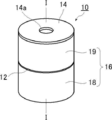
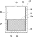
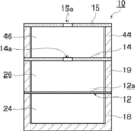
- FIG. 1 is a schematic perspective view showing an example of a soundproof structure (hereinafter referred to as a soundproof structure 10) according to the present invention.
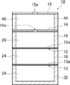
- FIG. 2 is an exploded view of the soundproof structure 10.
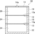
- FIG. 3 is a cross-sectional view taken along line II of the soundproof structure 10 illustrated in FIG.
- the soundproof structure 10 uses a membrane vibration to exhibit a sound absorbing function and selectively mute a sound having a specific frequency (frequency band).
- the soundproof structure 10 includes a plate-like member 14 having a through-hole 14a, a film-like member 12 arranged to face one surface of the plate-like member 14, and a plate-like member. And a support 16 that supports the member 14 and the film-like member 12.
- a first space 26 is formed between the plate-like member 14 and the film-like member 12, and a back space 24 is formed on the opposite side of the first space 26 across the film-like member 12. .
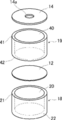
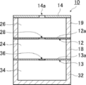
- the support body 16 is composed of a plurality of frames, and in the soundproof structure 10 shown in FIGS. 1 to 3, the support body 16 includes two inner frames 18 and an outer frame 19.
- the outer frame body 19 is a cylindrical frame body having an opening 40 penetrating in the thickness direction.
- the plate-like member 14 is disposed on one opening surface 41 of the outer frame body 19, and the film-like member 12 is disposed on the other opening surface 42.
- the inner frame 18 is a bottomed cylindrical frame having a bottom wall 22.
- the film-like member 12 is disposed on the opening surface 21 of the inner frame 18. That is, the membrane member 12 is supported by being sandwiched between the outer frame body 19 and the inner frame body 18.
- the inner frame body 18 and the outer frame body 19 are made of a rigid body, and support the edge of the plate-like member 14 by being fixed. I support it as possible.
- the “rigid body” can be regarded as a substantially rigid body. Specifically, the rigidity is sufficiently larger than the rigidity of the film-like member 12 and is stationary without vibrating while the film-like member 12 is vibrating. On the other hand, it is overwhelmingly thick and has extremely high bending rigidity. If the hardness is sufficiently large with respect to the film member 12, the vibration of the rigid body can be substantially ignored with respect to the vibration of the film member 12 when sound is incident.
- the edge of the membrane member 12 is a fixed end and is not vibrated because it is fixed to the inner frame 18 that is a rigid body. Whether or not the edge of the film-like member 12 (that is, the inner frame 18) does not vibrate (is stationary) can be confirmed by measurement using laser interference. Specifically, if the amount of displacement of the edge of the film-like member 12 is about 1/100 or less of the amplitude of the vibrating part (film part 12a) of the film-like member 12, it is regarded as a rigid body. The amount of displacement is inversely proportional to the product of Young's modulus (longitudinal elastic modulus) and the moment of inertia of the section.
- the cross-sectional second moment is proportional to the third power of the thickness and the first power of the width. Therefore, the displacement amount is proportional to 1 / (E ⁇ w ⁇ h 3 ) when Young's modulus E, thickness h, and width w are set. Therefore, in order to set the displacement amount to 1/100 or less, it is only necessary that (E ⁇ w ⁇ h 3 ) of the inner frame 18 is 100 times or more that of the film member 12.
- the film-like member 12 is vibrated by applying salt or white fine particles to the film-like member 12, it is visually observed by observing that the above-mentioned fine particles are still standing at the edge of the film-like member 12. Can be confirmed.
- the inner frame 18 is a bottomed cylindrical frame as shown in FIG. 2, and an opening 20 formed of a circular cavity is provided at the center portion in the radial direction.
- One end surface (outer end portion) of the inner frame 18 in the thickness direction is an opening surface 21.
- An edge (outer edge) of the film-like member 12 is fixed to the opening surface 21 of the inner frame 18.
- the membrane member 12 is supported by the inner frame 18 in a state in which the membrane portion 12a can vibrate.
- the membrane portion 12a is a membrane body portion of the membrane-like member 12 that faces the opening 20 inside the fixed outer edge and vibrates.
- the inner frame 18 is provided with a bottom wall 22 that closes the surface of the opening 20 opposite to the opening surface 21 on which the film-like member 12 is disposed. That is, the opening 20 of the inner frame 18 has a bottom surface at a position opposite to the opening surface 21.
- the bottom wall 22 may be comprised by the plate-shaped member, or may be comprised by thin members, such as a film.
- the outer frame body 19 corresponds to a cylindrical frame body, and is a cylindrical frame body as shown in FIG.
- the outer frame body 19 is formed with an opening 40 formed of a circular cavity that penetrates from one end of the outer frame body 19 to the other end in the thickness direction.
- the opening 40 of the outer frame 19 has the same diameter as the opening 20 of the inner frame 18.
- the edge of the film-like member 12 is fixed to the opening surface 42 of the outer frame 19 on the inner frame 18 side. Further, the edge (outer edge) of the plate-like member 14 is fixed to the opening surface 41 located on the opposite side of the outer frame 19 from the inner frame 18.
- the film member 12 is a circular thin film body whose outer shape is substantially the same as the opening surface 21 of the inner frame 18.
- the edge (outer edge) of the film-like member 12 is clamped and fixed to the opening surface 21 of the inner frame 18 and the opening surface 42 of the outer frame 19. Thereby, the film-like member 12 is supported by the inner frame body 18 and the outer frame body 19 in a state in which the film portion 12a can be vibrated.
- the plate-like member 14 is a circular plate-like member whose outer diameter is substantially the same size as the opening surface 41 of the outer frame body 19.
- the edge of the plate-like member 14 (outer edge) is fixed to the opening surface 41 of the outer frame 19. Further, a through hole 14 a is formed in a substantially central portion of the plate-like member 14. As shown in FIG. 1, the plate-like member 14 is disposed at the outer end in the thickness direction of the soundproof structure 10 and is exposed to the sound source.
- the soundproof structure 10 is configured by stacking the inner frame 18, the film member 12, the outer frame 19, and the plate member 14 in order from the inner side in the thickness direction. ing. As shown in FIG. 3, the film-like member 12 and the plate-like member 14 face each other via the outer frame 19 in the thickness direction.
- a first space 26 is formed between the plate-like member 14 and the film-like member 12 inside the soundproof structure 10.
- the first space 26 is sandwiched between the plate-like member 14 and the film-like member 12 in the thickness direction, and the periphery thereof is surrounded by the outer frame body 19.
- the plate-like member 14 and the film-like member 12 sandwiching the first space 26 are opposed to each other with the outer frame body 19 interposed therebetween.
- a back space 24 is formed inside the soundproof structure 10 on the side opposite to the first space 26 (that is, inside) across the membrane member 12.
- the back space 24 is a space surrounded by the membrane member 12 fixed to the opening surface 21 of the inner frame 18 and the inner frame 18.
- the closed space is a closed space. It has become.
- the plate-shaped member 14 is arrange
- the shaped member 14 closes one end surface (opening surface 41) of the opening 40 of the outer frame 19.
- a film member 12 is disposed between the outer frame body 19 and the inner frame body 18, and the film member 12 blocks the other end surface (opening surface 42) of the opening 20 of the outer frame body 19. It is out. That is, the first space 26 is a closed space like the back space 24.
- each sound absorbing portion absorbs a sound having a specific frequency. That is, there are a plurality of frequency bands in which the soundproof structure 10 of the present invention can absorb sound, and among them, the frequency band of sound absorption mainly contributed by the first sound absorbing part and the sound absorption by the second sound absorbing part. Frequency band.
- the first sound absorbing part is a sound absorbing part constituted by the film member 12, the inner frame 18 and the back space 24.
- the first sound absorbing portion absorbs sound at a relatively high frequency (for example, 3 kHz to 5 kHz) by the membrane vibration of the film-like member 12. That is, the frequency band of sound absorption mainly contributed by the first sound absorbing portion corresponds to the frequency band of sound absorption mainly due to the membrane vibration of the film-like member 12 adjacent to the back space 24.
- the second sound absorbing part is a sound absorbing part constituted by the plate-like member 14, the film-like member 12, the outer frame body 19, and the first space 26.
- the second sound absorbing portion absorbs sound by generating Helmholtz resonance by the through hole 14 a formed in the plate-like member 14 and the first space 26.
- the vibration of the film member 12 and the vibration of the gas (air) in the first space 26 are performed.
- the first sound absorbing unit selectively absorbs sound in a predetermined frequency band by the membrane vibration of the film-like member 12.
- the frequency of membrane vibration is determined by the thickness, hardness, size, fixing method, and the like of the membrane member 12.
- the membrane vibration has a fundamental vibration mode and a higher-order vibration mode.
- the frequency of at least one higher-order vibration mode existing at 1 kHz or more of the membrane vibration of the membrane member 12 adjacent to the back space 24 is obtained. It is preferable that the sound absorption coefficient at is higher than the sound absorption coefficient at the frequency of the fundamental vibration mode. Details of how this configuration has been achieved are described below.
- Various electronic devices such as copiers have a sound source such as an electronic circuit and an electric motor that are sources of noise, and each of these sound sources generates a loud sound with a specific frequency.
- a porous sound absorber generally used as a silencer means that the sound is silenced at a wide frequency, so that the noise of the frequency inherent to the sound source cannot be sufficiently silenced and becomes relatively easy to hear than other frequencies. was there.
- a silencer using a membrane vibration is known as a means for greatly muting a specific frequency sound.
- the frequency of noise generated by the electronic circuit and the electric motor described above has become higher.
- a silencing means using membrane vibration it is conceivable to increase the natural frequency of the membrane vibration by adjusting the hardness and size of the membrane member.
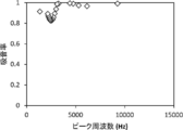
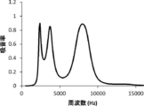
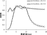
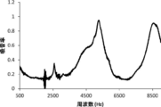
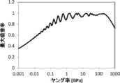
- the film-like member is too hard (or thick), the sound is likely to be reflected by the film. Therefore, as shown in FIG. 4, the higher the frequency of the fundamental vibration mode, the smaller the sound absorption (sound absorption rate) due to the membrane vibration.
- the membrane member needs to be hardened for higher frequency. Hardening the film-like member leads to an increase in reflection on the film surface. It is considered that the absorption is reduced because most of the sound is reflected from the surface of the film instead of being absorbed by the resonance vibration because a harder film-like member is required for resonance as the high-frequency sound is resonated. Therefore, it has been clarified that it is difficult to absorb a large amount of sound at a high frequency with a silencer using a membrane vibration using a fundamental vibration mode based on a conventional design theory. This characteristic is unsuitable for use in silencing high frequency specific sounds.
- the graph shown in FIG. 4 is a result of simulation using the finite element method calculation software COMSOLCOMver.5.3 (COMSOL Inc.).
- the calculation model was a two-dimensional axisymmetric structure calculation model, the frame was cylindrical, the diameter of the opening was 10 mm, and the thickness of the back space was 20 mm.
- the film-like member was 250 ⁇ m in thickness, and the Young's modulus, which is a parameter representing the hardness of the film-like member, was variously changed in the range of 0.2 GPa to 10 GPa.
- the evaluation was performed with the normal incident sound absorption coefficient arrangement, and the maximum value of the sound absorption coefficient and the frequency at that time were calculated.
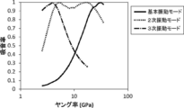
- the sound absorption coefficient at the frequency of at least one higher-order vibration mode existing at 1 kHz or more of the membrane vibration of the membrane member 12 is set.
- the structure has a higher sound absorption rate than the fundamental vibration mode frequency.
- the first sound absorbing portion is made to increase the sound absorption coefficient at the higher order natural frequency such as the second order and third order natural frequencies, and the membrane vibration of the higher order vibration mode. Since it is not necessary to harden (or thicken) the film-like member, the sound can be suppressed from being reflected by the film surface, and a high sound absorption effect can be obtained even at a high frequency. Can do.
- the 1st sound absorption part which is a single layer film structure absorbs sound using a membrane vibration, it can mute suitably the sound of a specific frequency with a small light weight.
- the present inventors estimated the mechanism by which the higher-order vibration mode is excited as follows. There are frequency bands of fundamental vibration mode and higher-order vibration mode determined by the conditions (thickness, hardness, size, fixing method, etc.) of the film-like member. Which mode is strongly excited to contribute to sound absorption? Is determined by the distance of the back space. This will be described below.
- the resonance of the sound absorbing structure using the film-like member is considered separately, there are a part involving the film-like member and a part involving the back space. Therefore, sound absorption occurs due to these interactions.
- a resonance phenomenon occurs when this total acoustic impedance matches the acoustic impedance of the medium fluid (such as air).
- the acoustic impedance Zm of the membrane member is determined by the specification of the membrane member.
- the component (mass law) according to the equation of motion by the mass of the membrane member and the membrane member are fixed. Therefore, resonance occurs when components (stiffness law) governed by tension such as a spring coincide with each other.
- the higher-order vibration mode is resonance due to the shape of the membrane vibration that is more complicated than the fundamental vibration.
- the band for the fundamental vibration mode becomes wide.
- the sound absorption is reduced because the film-like member is hard and easily reflected.
- the film member has a condition where the higher vibration mode is likely to occur, such as by reducing the thickness of the film member, the frequency bandwidth in which the fundamental vibration mode is generated becomes smaller, and the higher vibration mode exists in the high frequency region. It becomes.
- the acoustic impedance Zb in the back space is different from the impedance in the open space because the flow of air-propagating sound is restricted by the closed space or the through-hole portion, and the back space becomes harder as the thickness of the back space becomes smaller.
- the resonance of the lower frequency sound becomes smaller because the back space is too small for the wavelength. That is, the frequency of the sound that can resonate is determined by the change in the back distance.
- the frequency of the fundamental vibration and the higher-order vibration in another band are determined depending on the specifications of the membrane member.
- the simulation was performed using the acoustic module of the finite element method calculation software COMSOL ver.5.3 (COMSOL Inc.).
- the calculation model of the soundproof structure 10 will be described.
- the frame body has a cylindrical shape, the opening has a diameter of 20 mm, the film member has a thickness of 50 ⁇ m, and the Young's modulus of the film member has a Young's modulus of a PET (polyethylene terephthalate) film. It was set to 4.5 GPa.
- the calculation model was a two-dimensional axisymmetric structure calculation model.
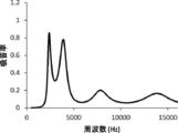
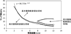
- FIG. 5 is a graph plotting the frequency at which the sound absorption rate is maximum in each calculation model (hereinafter referred to as peak frequency) and the sound absorption rate at the peak frequency.
- peak frequency the frequency at which the sound absorption rate is maximum in each calculation model
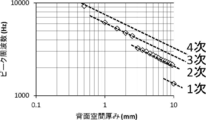
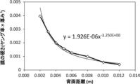
- FIG. 6 shows a graph in which the relationship between the peak frequency of each calculation model and the thickness of the back space is plotted as a logarithm, and a line is drawn for each order of the vibration mode.
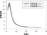
- 7 and 8 are graphs showing the relationship between the frequency and the sound absorption coefficient in each calculation model when the thickness of the back space is 7 mm, 5 mm, 3 mm, 2 mm, 1 mm, and 0.5 mm.
- the peak frequency of the sound absorption rate is increased by reducing the thickness of the back space.
- the peak frequency does not increase continuously on the logarithmic axis, but a plurality of discontinuous changes occur on the logarithmic axis. .
- This characteristic indicates that the vibration mode in which the sound absorption coefficient is maximum is shifted from the fundamental vibration mode to a higher-order vibration mode or a vibration mode having a higher order of the higher-order vibration mode. That is, it was found that the high-order vibration mode is easily excited by the thin film-like member, and that the sound absorption effect by the high-order vibration mode rather than the fundamental vibration mode appears greatly by reducing the thickness of the back space.
- a large sound absorption coefficient in the high frequency range is not caused by the fundamental vibration mode but caused by resonance by the higher order vibration mode. From the line drawn for each order of the vibration mode shown in FIG. 6, the thinner the back space, the higher the frequency in the vibration mode, that is, the frequency at which the sound absorption coefficient is the highest. I understand.
- the film thickness of the film-like member is as thin as 50 ⁇ m.
- the higher-order vibration mode has a complicated vibration pattern on the film as compared with the fundamental vibration mode. That is, it has a plurality of antinodes on the membrane. Therefore, compared with the fundamental vibration mode, bending with a smaller plane size is necessary, and there are many vibration modes that require bending near the membrane fixing portion (the edge of the membrane member). It is important to reduce the film thickness in order to use the higher-order vibration mode because the smaller the film thickness is, the easier it is to bend.
- a structure with a thin film thickness is a system in which the hardness of the film-like member is small. In such a system, reflection with respect to high-frequency sound is small, and it is considered that a large sound absorption rate can be obtained even on the high-frequency side.
- the sound absorption coefficient has a maximum value (peak) at a plurality of frequencies.
- the frequency at which the sound absorption coefficient is a maximum value is the frequency of a certain vibration mode.
- the lowest frequency of about 1500 Hz is the frequency of the fundamental vibration mode. That is, in any calculation model, the frequency of the fundamental vibration mode is about 1500 Hz.
- the frequency which becomes the maximum value existing in the frequency higher than 1500 Hz that is the fundamental vibration mode is the frequency of the higher-order vibration mode.
- the sound absorption rate at the frequency of the higher-order vibration mode is higher than the sound absorption rate at the frequency of the fundamental vibration mode.
- the fundamental vibration mode is a vibration mode that appears on the lowest frequency side
- the higher-order vibration mode is a vibration mode other than the fundamental vibration mode.
- Whether the vibration mode is the fundamental vibration mode or the higher-order vibration mode can be determined from the state of the film member 12.
- the center of gravity of the film-like member 12 has the largest amplitude, and the amplitude in the vicinity of the peripheral fixed end (edge) is small.
- the film member 12 has a speed in the same direction in all the regions.
- the membrane vibration in the higher-order vibration mode the film-like member 12 has a portion having a speed in the reverse direction depending on the position.
- the edge of the fixed film member 12 becomes a vibration node, and no node exists on the film portion 12a.
- the high-order vibration mode in addition to the edge portion (fixed end portion) according to the above definition, there is a portion serving as a vibration node on the membrane portion 12a. it can.
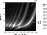
- vibration mode analysis vibration mode can be directly observed by measuring membrane vibration using laser interference.
- the position of the node can be visualized by oscillating the salt or white fine particles on the membrane surface, and this method can be used for direct observation. This visualization of the vibration mode is known as a Cladoni figure.
- the frequency in each vibration mode can also be obtained analytically.
- the frequency in each vibration mode can be obtained for an arbitrary film shape.
- the sound absorption coefficient can be obtained by sound absorption coefficient evaluation using an acoustic tube.
- a measurement system for normal incidence sound absorption coefficient according to JIS A 1405-2 is prepared and evaluated.
- WinZacMTX manufactured by Nippon Acoustic Engineering can be used.
- the internal diameter of the acoustic tube is 20 mm, and the soundproof structure to be measured is arranged at the end of the acoustic tube with the outer end surface facing the front side (acoustic incident side), and the reflectance is measured.
- the sound absorption coefficient is evaluated by obtaining the reflectance. It is possible to measure up to high frequency as the diameter of the acoustic tube is reduced. Since it is necessary to measure the sound absorption characteristics up to high frequencies this time, an acoustic tube having a diameter of 20 mm is selected.
- the thickness of the back space 24 the film shape
- the size, thickness, hardness, density, etc. of the member 12 may be adjusted.
- the thickness of the back space 24 (La in FIG. 3) is preferably 10 mm or less, more preferably 5 mm or less, further preferably 2 mm or less, and particularly preferably 1 mm or less. If the thickness of the back space 24 is not uniform, the average value may be in the above range.
- the thickness of the film-like member 12 is preferably less than 100 ⁇ m, more preferably 70 ⁇ m or less, and further preferably 50 ⁇ m or less. In addition, when the thickness of the film-shaped member 12 is not uniform, an average value should just be the said range.
- the Young's modulus of the membrane member 12 is preferably 1 MPa to 100 GPa, more preferably 10 MPa to 50 GPa, and most preferably 100 MPa to 30 GPa.
- the density of the film member 12, it is preferably, more preferably from 100kg / m 3 ⁇ 20000kg / m 3, 500kg / m 3 ⁇ 10000kg / m 3 is 10kg / m 3 ⁇ 30000kg / m 3 Most preferred.
- the shape of the membrane portion 12a of the membrane member 12 (the shape of the membrane vibrating region), in other words, the shape of the opening cross section of the frame (the inner frame 18 and the outer frame 19) is not particularly limited.
- Other quadrilaterals such as squares, rectangles, rhombuses or parallelograms, polygons including regular triangles such as regular triangles, isosceles triangles, right triangles, regular pentagons, regular hexagons, circles, ellipses It may be a shape or the like, or may be indefinite.
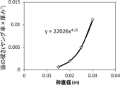
- the size of the membrane portion 12a of the membrane-like member 12 (the size of the membrane vibrating region), in other words, the size of the opening cross section of the frame is preferably 1 mm to 100 mm in terms of the equivalent circle diameter (Lc in FIG. 3). 3 mm to 70 mm is more preferable, and 5 mm to 50 mm is further preferable.
- the sound absorption rate is higher than the sound absorption rate at the frequency of the fundamental vibration mode, and the sound absorption rate at the frequency of at least one higher-order vibration mode is preferably 20% or more, more preferably 30% or more, It is more preferably 50% or more, particularly preferably 70% or more, and most preferably 90% or more.
- a higher-order vibration mode having a higher sound absorption rate than the sound absorption rate at the frequency of the fundamental vibration mode is also simply referred to as “high-order vibration mode”, and the frequency is also simply referred to as “high-order vibration mode frequency”. .
- the sound absorption rate in the frequency of two or more higher-order vibration modes is 20% or more, respectively.
- the sound absorption rate is 20% or more at a plurality of higher-order vibration mode frequencies, sound can be absorbed at a plurality of frequencies.
- the high-order vibration mode in which the sound absorption coefficient is 20% or more is continuously present. That is, for example, it is preferable that the sound absorption coefficient at the frequency of the secondary vibration mode and the sound absorption coefficient at the frequency of the tertiary vibration mode are each 20% or more. Furthermore, when there is a continuous high-order vibration mode in which the sound absorption coefficient is 20% or more, the sound absorption coefficient is preferably 20% or more over the entire band between the frequencies of these high-order vibration modes. Thereby, a sound absorption effect can be obtained in a wide band.
- the second sound absorbing portion is a portion that absorbs sound by Helmholtz resonance when it is a single body (when the film-like member is regarded as a rigid body). That is, the second sound absorbing portion absorbs sound by generating Helmholtz resonance by the through hole 14 a formed in the plate-like member 14 and the first space 26.
- the soundproof structure of the present invention since a part of the partition wall surrounding the first space 26 is constituted by the membrane member 12, the vibration of the membrane member 12 and the gas (air) in the first space 26 are provided.
- a higher frequency band for example, 8 kHz
- FIGS. 9 and 10 show a soundproof structure having a configuration in which the fundamental frequency of membrane vibration in the first sound absorbing unit alone is 1.5 kHz, and the fundamental frequency of Helmholtz resonance in the second sound absorbing unit alone is 6.0 kHz. It is the figure which showed distribution of the sound pressure in a soundproof structure when the sound of sound pressure 1Pa injects from the upper side in a figure with frequency 3.3kHz and 8.6kHz, respectively. As is well known, the sound pressure is the fluctuation of the pressure due to sound from the atmospheric pressure.
- the first sound absorbing unit can absorb sound even at frequencies in higher-order vibration modes other than the fundamental frequency of membrane vibration. Therefore, for example, a sound having a frequency lower than the fundamental frequency of the Helmholtz resonance and a frequency that can be absorbed by the first sound absorbing part (corresponding to higher-order vibration, for example, a sound near 3.3 kHz) is transmitted to the soundproof structure. The sound is absorbed mainly by the membrane vibration of the first sound absorbing part. At that time, the sound pressure in the space inside the membrane-like member 12 (space on the bottom wall side), that is, the back space 24 becomes higher due to the occurrence of membrane vibration.
- the space outside the membrane member 12 (the space on the sound incident side), that is, the air in the first space has the same sound pressure phase as the membrane vibration of the membrane member 12, Vibrates in sync with direction. Therefore, as shown in FIG. 9, the sound pressure is not particularly increased. Therefore, the mechanism in this case is mainly the sound absorption by the first sound absorbing portion, that is, the fundamental vibration or higher order vibration of the membrane resonator.
- the first between the plate-like member 14 and the film-like member 12 is shown in FIG.
- the sound pressure in the space 26 is increased. This is because the phase of the membrane vibration of the membrane member 12 of the first sound absorbing portion and the phase of the sound vibration of the air in the first space 26 due to the Helmholtz resonance of the second sound absorbing portion (particularly the phase of the neck portion of the Helmholtz resonance). This is because they vibrate so as to be in opposite phases.
- the local velocity component of the sound passing through the film-like member 12 and the plate-like member 14 becomes a canceling relationship due to the phase relationship between the two resonators, and thus becomes small. Since the local velocity component in the plane direction in the first space remains, the sound easily flows in the plane direction, and the sound pressure in the first space 26 increases. Therefore, the distribution is as shown in FIG. As described above, while the Helmholtz resonance is the main factor, the effect that the volume of the first space 26 is effectively narrowed by the cancellation of the local velocity vector in the vertical direction by the lower film type resonance structure (Helmholtz resonance). The sound phase from the neck portion of the first space 26 and the film portion on the bottom surface of the first space 26 have opposite sound phases), and the sound absorption effect appears at a frequency higher than the frequency of the Helmholtz resonance alone.
- FIG. 9 and FIG. 10 show the results of simulation using the acoustic module of the finite element method calculation software COMSOL ver.5.3 (COMSOL Inc.). Specifically, a soundproof structure in which a circular plate-shaped member 14, an outer frame 19, a film-shaped member 12, and an inner frame 18 are stacked in this order and the back space 24 is a closed space is modeled. The coupled analysis calculation of sound and structure was performed. At this time, structural mechanics calculation is performed for the film-like member 12, sound air propagation is calculated for the back space 24 and the first space 26, and simulation is performed in a manner that these acoustic calculation and structural calculation are strongly coupled. went. The calculation model was a two-dimensional axisymmetric structure calculation model.
- thermoviscous acoustic calculation was performed in the through hole where Helmholtz resonance occurred, and the calculation including the frictional heat absorption due to viscous friction was performed accurately. These physical modes were coupled and calculated.
- the calculation model of the soundproof structure 10 will be described.
- the inner frame 18 and the outer frame 19 are cylindrical, and the diameters of the opening 20 and the opening 40 are 20 mm.
- the film-like member 12 had a thickness of 50 ⁇ m, and the Young's modulus was 4.5 GPa, which is the Young's modulus of a PET (polyethylene terephthalate) film.
- the plate-like member 14 had a thickness of 2 mm, and a through hole 14a having a diameter of 8 mm was formed at the center.
- the thickness of each of the back space 24 and the first space 26 was 2 mm.
- the evaluation was performed with the normal incident sound absorption coefficient arrangement, and the maximum value of the sound absorption coefficient and the frequency at that time were calculated.
- the film-like member 12 and the air in the first space 26 vibrate in opposite phases in the second sound absorbing portion superimposed on the first sound absorbing portion.
- a higher frequency sound can be absorbed.
- the soundproof structure 10 of the present invention can absorb sound simultaneously in both the sound absorption frequency band mainly contributed by the first sound absorption part and the sound absorption frequency band by the second sound absorption part. It is possible to absorb sound over the entire range. The effectiveness of the soundproof structure 10 of the present invention will be described in detail with reference to FIGS.
- FIG. 11 is a reference example 1, which is a soundproof structure having only a first sound absorbing portion (that is, a soundproof structure having only a single-layer film structure without the plate-like member 14, the outer frame 19 and the first space 26). And is a graph showing the relationship between the frequency and the sound absorption rate in the following (also referred to as “soundproof structure of a membrane vibration alone”).
- FIGS. 12 and 13 are reference examples 2 and 3, which are provided with only the second sound absorbing portion and the soundproof structure in which the film-like member 12 is regarded as a rigid body (that is, the film without the inner frame 18 and the back space 24).
- FIGS. 14 to 16 are graphs showing the relationship between the frequency and the sound absorption rate in Examples 1 to 3 of the soundproof structure 10 according to an example of the present invention, respectively.
- the graphs shown in FIGS. 11 to 16 are in accordance with the acoustic tube measurement method described above, with the soundproof structure at the end of the soundtube having a plate-like member (a membrane-like member for a soundproof structure with a single membrane vibration) on the front side. It arrange
- the inner frame 18 is a cylindrical acrylic plate, the outer diameter of the inner frame 18 is 40 mm, the diameter of the opening 20 is 20 mm, and the film-like member 12 is thick. A 50 ⁇ m PET (polyethylene terephthalate) film is used.
- the soundproof structure of the membrane vibration alone has a structure in which a back plate made of a rigid body (aluminum plate having a thickness of 100 mm) is pressed against the bottom surface of the back space 24. That is, in the soundproof structure with a single membrane vibration, the back space 24 is a closed space. Moreover, the thickness of the back space 24 is 2 mm.
- the inner frame 18 was produced by processing a 2 mm thick acrylic plate (manufactured by Hikari Co., Ltd.) using a laser cutter. Also, the inner frame 18 and the film-like member 12 are bonded to each other with a double-sided tape (the power of ASKUL's site) with the outer edge of the doughnut-shaped acrylic plate and the outer edge of the PET film aligned. It was. Therefore, the range in which the membrane member can vibrate is 20 mm in diameter, and the vibration is fixed at the end.
- the normal incident sound absorption coefficient was measured in the same manner as described below. Using a laser cutter, make one circular plate with an outer diameter of 40 mm, and double-sided tape (ASKUL) with the outer diameter of the outer edge of the doughnut-shaped plate and the outer edge of the circular plate matched. A frame was prepared by bonding a circular plate to the surface of the donut-shaped plate opposite to the membrane member using the power of the manufacturing site. Even in the above configuration, the same measurement result as that obtained by pressing a rigid body made of an aluminum plate having a thickness of 100 mm on the back surface of the soundproof structure was obtained.
- ASKUL double-sided tape
- the soundproof structure of the Helmholtz resonance unit is an acrylic plate in which the outer frame 19 is a cylindrical acrylic plate, the outer frame 19 has an outer diameter of 40 mm, the opening 40 has a diameter of 20 mm, and the plate member 14 has a thickness of 2 mm. It is said. Further, a through hole 14 a is provided at the center position of the plate-like member 14.
- the soundproof structure of the membrane vibration alone has a structure in which a back plate made of a rigid body (a 100 mm thick aluminum plate) is pressed against the bottom surface of the back space 24. The thickness of the first space 26 is 2 mm.
- FIG. 12 shows the case where the diameter of the through hole 14a formed in the plate member 14 is 6 mm (Reference Example 2)
- FIG. 13 shows the case where the diameter of the through hole 14a formed in the plate member 14 is 8 mm. (Reference Example 3).
- a case where the diameter of the through hole 14a formed in the plate-like member 14 is 10 mm is referred to as a reference example 4.
- an inner frame 18, a film member 12, an outer frame 19, and a plate member 14 are arranged in order from the inside.
- the inner frame 18 and the outer frame 19 are made of a cylindrical acrylic plate, each having an outer diameter of 40 mm, an opening having a diameter of 20 mm, and the membrane member 12 is a PET (polyethylene terephthalate) film having a thickness of 50 ⁇ m. It is.
- the plate member 14 is an acrylic plate having a thickness of 2 mm, and a through hole 14 a is provided at the center position of the plate member 14.
- the soundproof structure 10 according to an example of the present invention is provided with a bottom wall 22 at the bottom of the opening 20 of the inner frame 18. That is, in the soundproof structure 10 according to an example of the present invention, the back space 24 is a closed space. Moreover, in the soundproof structure 10 which concerns on an example of this invention, the thickness of each of the back space 24 and the 1st space 26 is 2 mm.
- FIG. 14 shows the frequency and sound absorption coefficient when the diameter of the through-hole 14a formed in the plate-like member 14 is 6 mm, that is, when the configuration of Reference Example 1 and Reference Example 2 is combined (referred to as Example 1). It is the graph which measured the relationship.
- FIG. 14 shows the frequency and sound absorption coefficient when the diameter of the through-hole 14a formed in the plate-like member 14 is 6 mm, that is, when the configuration of Reference Example 1 and Reference Example 2 is combined (referred to as Example 1). It is the graph which measured the relationship.
- FIG. 1 shows the frequency and sound absorption coefficient when the diameter of the
- FIG. 15 shows the frequency and sound absorption coefficient when the diameter of the through hole 14a formed in the plate-like member 14 is 8 mm, that is, when the configuration of Reference Example 1 and Reference Example 3 is combined (referred to as Example 2).
- FIG. 16 is a graph in which the diameter of the through-hole 14a formed in the plate-like member 14 is 10 mm, that is, the configuration in which Reference Example 1 and Reference Example 4 are combined (implemented). It is the graph which measured the relationship between the frequency of (example 3) and a sound absorption rate.
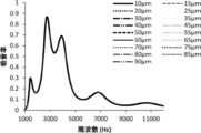
- FIG. 11 that the soundproof structure of the membrane vibration alone has a structure that absorbs sound at a plurality of frequencies by vibrations of the fundamental vibration mode and the higher-order vibration mode of the membrane member 12 adjacent to the back space 24.
- FIG. 11 shows that the frequency of the fundamental vibration mode is 1.7 kHz.
- a plurality of high sound absorption peaks appear in a band of 3 kHz to 5 kHz, and each peak shows a high sound absorption coefficient.
- the sound absorption rate is less than 50%.
- a high sound absorption coefficient can be obtained by the membrane vibration in the fundamental vibration mode or the higher order vibration mode of the membrane in a specific frequency band. In the vibration mode, the sound absorption rate tends to be low.
- the soundproof structure of the Helmholtz resonance alone absorbs sound in a band centered on one frequency by the frequency of the fundamental resonance mode of Helmholtz resonance.
- the frequency of the fundamental resonance mode is 4.5 kHz.
- the frequency of the fundamental resonance mode is 6.0 kHz.
- the peak of the sound absorption coefficient is gentle compared to the case of the membrane vibration alone. It can also be seen that no peaks other than the fundamental resonance mode appear.
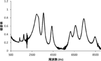
- each of the plurality of sound absorption peaks appearing in the band of 3.0 kHz to 5.0 kHz exhibits a high sound absorption rate.
- the sound absorption peak that appears in the vicinity of 6.0 kHz to 9.0 kHz shows a sound absorption rate of 70% or more.
- Table 2 also shows the value of the ratio f h1 / f m1 between the fundamental frequency f m1 of the membrane vibration and the fundamental frequency f h1 of the Helmholtz resonance.
- the fundamental frequency f m1 of the membrane vibration and the fundamental frequency f h1 of the Helmholtz resonance are separated by more than twice (f h1 ⁇ 2 ⁇ f m1 is satisfied).
- the sound absorption characteristics of Examples 1 to 3 having a configuration in which a Helmholtz resonator and a membrane vibration resonator are stacked have a peak frequency on the high frequency side higher than the fundamental frequency of either the Helmholtz resonator alone or the membrane vibration alone. Appears and has a large sound absorption coefficient.
- the frequency band of sound absorption mainly contributed by the first sound absorption unit is, for example, 3 kHz to 5 kHz
- the sound absorption by the second sound absorption unit is Is in the range of 6.0 kHz to 9 kHz, for example. Therefore, the soundproof structure 10 according to an example of the present invention can simultaneously absorb a plurality of relatively high frequency sounds such as motor sounds and inverter sounds.
- the frequency band of sound absorption mainly contributed by the first sound absorbing unit is referred to as “low frequency side sound absorbing frequency band”
- the frequency band of sound absorption by the second sound absorbing unit is referred to as “high frequency side sound absorbing frequency band”. It will be called “frequency band”.
- the sound absorption peak that appears in the sound absorption frequency band on the low frequency side is referred to as “the sound absorption peak on the low frequency side”
- the sound absorption peak that appears in the sound absorption frequency band on the high frequency side is referred to as “the sound absorption peak on the high frequency side”.
- the frequency of the sound absorption peak on the low frequency side can be changed by adjusting the thickness of the back space 24, the thickness of the membrane member 12 adjacent to the back space 24, and the like.
- the frequency of the sound absorption peak on the high frequency side adjusts the thickness of the first space 26, the thickness of the plate-like member 14, the size of the through hole 14a formed in the plate-like member 14, the thickness of the film-like member 12, and the like. It can be changed.
- the frequency of the sound absorption peak on the low frequency side and the high frequency side can be independently controlled. As a result, the frequency of each sound absorption peak can be appropriately controlled in accordance with the frequency of the noise to be absorbed, and as a result, sound absorption is efficiently performed.
- the ability to independently change the frequencies of the first sound absorption peak and the second sound absorption peak is also effective for simple noise caused by vibration of a metal rod or the like. That is, in the conventional sound absorbing device using membrane vibration, the vibration mode of the membrane (resonance based on two-dimensional vibration) and the vibration mode of a metal rod or the like (resonance based on one-dimensional vibration) have frequency intervals for respective orders. Because of the difference, it is difficult to match the resonance peak of the membrane vibration at a plurality of frequencies with respect to simple noise derived from a metal rod, and it is difficult to suitably absorb such simple noise. The same was true for motor, inverter, and fan noises, where peak noise appears at integer multiples.
- the soundproof structure 10 of the present invention can suitably change the frequency of the sound absorption peak in each sound absorption frequency band as described above, and is therefore suitable for absorbing simple noise derived from a metal rod.
- the soundproof structure 10 of the present invention can suitably change the frequency of the sound absorption peak in each sound absorption frequency band as described above, and is therefore suitable for absorbing simple noise derived from a metal rod.
- the soundproof structure of the present invention is often vulnerable to impact on the film surface because a thin film is used. It is possible to prevent an object from coming into direct contact with the membrane member 12. That is, the plate member 14 also serves as a protective member that protects the film member 12.
- the soundproof structure of the present invention has a configuration in which a plate-like member having a through-hole and a film-like member are arranged at a predetermined distance from each other, the soundproofing structure can be made small, light, and thin, and the installation space for the silencer can be reduced. It can be suitably used for limited electronic devices.
- the fundamental frequency of the membrane vibration of the first sound absorbing part is set to f m1
- the fundamental frequency of the Helmholtz resonance when the film-like member is regarded as a rigid body in the second sound absorbing part is set to f m1.
- h1 it has a configuration satisfying f h1 ⁇ 2 ⁇ f m1 .
- f h1 ⁇ 2 ⁇ fm 1 By adopting a configuration satisfying f h1 ⁇ 2 ⁇ fm 1 , as described above, it is possible to obtain a sound absorption effect at a higher frequency due to the interaction between the membrane vibration of the membrane-like member 12 and the Helmholtz resonance. This point will be described below using simulation results.
- the outer frame was cylindrical, the diameter of the opening was 20 mm, and the thickness of the first space was 2 mm.
- the plate-like member 14 had a thickness of 2 mm, and a through hole 14 a having a diameter of 8 mm was provided at the center position.
- the evaluation was performed with a normal incident sound absorption coefficient arrangement, and the relationship between the frequency and the sound absorption coefficient was calculated.
- the inside of the aperture hole where Helmholtz resonance is generated is accurately calculated including frictional heat absorption due to viscous friction by performing thermoviscous acoustic calculation.
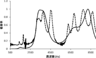
- FIG. 17 shows the result of the simulation (relationship between the calculated frequency and the sound absorption coefficient).
- the simulation result is indicated by a solid line
- the actual measurement result (measurement result of FIG. 15) is indicated by a dotted line as contrast information.
- the actual measurement result has a larger number of sound absorption peaks than the simulation result, and the degree of change in the sound absorption rate at each peak is large, but the overall trend is the difference between the actual measurement result and the simulation result.
- FIG. 18 is a graph showing the relationship between the frequency and the sound absorption coefficient when the through-hole diameter is 2 mm (simulation 2-1).
- FIG. 19 shows a graph showing the relationship between the frequency and the sound absorption coefficient when the through hole diameter is 5 mm (simulation 2-2).
- FIG. 20 shows a graph showing the relationship between the frequency and the sound absorption coefficient when the through-hole diameter is 10 mm (Simulation 2-3).
- FIG. 21 shows a graph showing the relationship between the frequency and the sound absorption coefficient when the through-hole diameter is 15 mm (simulation 2-4).
- a simulation 2-1 shown in a graph in FIG. 18 corresponds to a comparative example because the fundamental frequency f h1 of the Helmholtz resonance is 1.4 kHz and f h1 ⁇ 2 ⁇ f m1 is not satisfied.
- strong sound absorption derived from Helmholtz resonance appeared at 1.4 kHz.
- the frequency is equal to or higher than the Helmholtz resonance frequency, and in this case, the reflectance by the Helmholtz resonator is increased. Therefore, since the sound is reflected on the surface and it is difficult for the sound to reach the film-like member, the sound absorption effect due to the membrane vibration does not appear much.
- the fundamental frequency f h1 of the Helmholtz resonance is 4.1 kHz, 7 kHz, respectively. .7KHz, a 14.1KHz, both of which correspond to the embodiment of the present invention satisfies the f h1 ⁇ 2 ⁇ f m1.
- it has a low frequency side sound absorption region derived from membrane vibration, and also has a sound absorption region on the high frequency side. In this way, sound can be absorbed in the two sound absorption regions.
- the simulation 2-4 shown in the graph of FIG. 21 the sound absorption due to the membrane vibration appears, but the sound absorption due to the Helmholtz resonance is small. This is thought to be due to the fact that the effect of Helmholtz resonance is reduced because the through-hole diameter is too large.
- the calculation is performed by the simulation of the frequency and the sound absorption coefficient at each through-hole diameter from 1 mm to 19 mm. From the simulation result, the maximum sound absorption coefficient in the low frequency side sound absorption region and the frequency at which the sound absorption coefficient is the maximum (sound absorption frequency). And the frequency at which the sound absorption coefficient is maximum in the high frequency side sound absorption region and the frequency at which the sound absorption coefficient is maximum (sound absorption frequency) are read. The results are shown in FIG. 22 and FIG. The low frequency side sound absorption region was a frequency region of 4 kHz or less, and the high frequency side sound absorption region was a frequency region of 4.8 kHz or more.
- FIG. 22 shows that the low frequency side sound absorption region has a sound absorption coefficient of 0.7 or more even if the through hole diameter is changed. Further, FIG. 23 shows that the sound absorption frequency is shifted to the high frequency side according to the size of the through hole diameter up to about 5 mm of the through hole diameter, but the sound absorption frequency does not change even if it is larger than 5 mm.
- the sound absorption rate is low when the through-hole diameter is too small or too large.
- the sound absorption coefficient is 40% (0.4) or more when the through hole diameter is 4 mm to 12 mm, and the sound absorption coefficient is 50% (0.5) or more when the through hole diameter is 4 mm.
- the sound absorption coefficient is 80% (0.8) or more in the range of 5 to 10 mm.
- FIG. 23 shows that the sound absorption frequency is shifted to the high frequency side according to the size of the through hole diameter up to about 10 mm of the through hole diameter, but the sound absorption frequency does not change even if it is larger than 10 mm. That is, in the example of FIG. 22 and FIG. 23, it was found that when the through hole diameter is larger than 10 mm, the frequency in the high frequency side sound absorption region does not change and the sound absorption rate decreases.
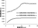
- FIG. 24 shows the through-hole diameter, a graph showing the relationship between the fundamental frequency of the Helmholtz resonator for the fundamental frequency f m1 of the original film and vibration ratio f h1 / f m1 of f h1.
- the right axis shows the fundamental frequency f h1 of Helmholtz resonance.
- FIG. 24 shows that the fundamental frequency of Helmholtz resonance is more than twice the fundamental frequency of membrane vibration when the through-hole diameter is 4 mm or more, which is the condition where the sound absorption coefficient exceeds 50% in FIG. Therefore, in order to obtain a high sound absorption coefficient in the high frequency side sound absorption region, it is necessary that “the fundamental frequency f h1 of Helmholtz resonance is at least twice the fundamental frequency f m1 of membrane vibration”.
- FIG. 24 shows that the fundamental frequency of Helmholtz resonance is 7700 Hz when the through-hole diameter is 10 mm. At this time, from FIG.
- the sound absorption peak frequency on the high frequency side of the laminated sound absorbing structure is 8000 Hz, which substantially matches the fundamental frequency of Helmholtz resonance in which the film-like member is regarded as a rigid body. And in the larger through-hole diameter than this, a high frequency side sound absorption coefficient becomes small, and a frequency does not change. Therefore, it is preferable that the fundamental frequency f h1 of Helmholtz resonance in which the film-like member is regarded as a rigid body is smaller than the maximum sound absorption frequency on the high frequency side of the soundproof structure.
- Simulation 3 Similar to simulation 2, except that the thickness of the plate member 14 was changed to 3 mm, the simulation was performed by changing the diameter (through hole diameter) of the through hole 14 a formed in the plate member 14 from 1 mm to 19 mm in 1 mm increments. . From the simulation results, the maximum sound absorption rate in the low frequency side sound absorption region and the frequency at which the sound absorption rate is maximum (sound absorption frequency), and the maximum sound absorption rate and sound absorption rate in the high frequency side sound absorption region (sound absorption frequency). ) Are shown in FIG. 25 and FIG.
- FIG. 25 shows that the low frequency side sound absorption region has a sound absorption coefficient of 0.6 or more even if the through hole diameter is changed.
- FIG. 26 shows that the sound absorption frequency is shifted to the high frequency side according to the size of the through hole diameter up to about 5 mm of the through hole diameter, but the sound absorption frequency does not change even if it is larger than 5 mm.
- the sound absorption rate is lowered when the through-hole diameter is too small or too large.
- the sound absorption coefficient is 40% (0.4) or more when the through hole diameter is in the range of 4 mm to 13 mm, and the sound absorption coefficient is 50% (0.5) or more when the through hole diameter is 4 mm.
- the sound absorption coefficient is 80% (0.8) or more in the range of 5 mm to 11 mm.
- FIG. 26 shows that the sound absorption frequency is shifted to the high frequency side according to the size of the through hole diameter up to about 10 mm of the through hole diameter, but the sound absorption frequency does not change even if it is larger than 10 mm.
- soundproof structure of the present invention in the second sound absorbing part, the fundamental frequency of Helmholtz resonance when regarded membrane-like member and the rigid and f h1, the fundamental frequency of the membrane vibration of the first sound absorbing part
- f m1 by satisfying f h1 ⁇ 2 ⁇ f m1, it is possible to obtain a sound absorbing effect at higher frequencies by the interaction of the membrane vibration and Helmholtz resonance of the film member 12, also a plurality of frequency bands Sound absorption effect can be obtained.
- the fundamental frequency f h1 of the Helmholtz resonance preferably satisfies 2.00 ⁇ f m1 ⁇ f h1 ⁇ 7.00 ⁇ f m1 , and 2.25 ⁇ f m1 More preferably, ⁇ f h1 ⁇ 6.50 ⁇ f m1 is satisfied, and it is more preferable that 2.50 ⁇ f m1 ⁇ f h1 ⁇ 6.00 ⁇ f m1 is satisfied.
- the fundamental frequency of Helmholtz resonance of the second sound absorbing part may be adjusted by adjusting the thickness of the first space 26, the size of the through hole 14a, the thickness of the plate-like member 14, and the like.
- the fundamental frequency of Helmholtz resonance is determined by the opening area of the through hole, the length of the through hole, and the volume of the back space.
- c is the speed of sound
- V is the volume of the first space
- S is the cross-sectional area of the through hole
- L is the length of the through hole (more precisely, the length considering the opening end correction distance).
- the length of the through hole is not necessarily the same as the thickness of the plate member.
- punching or the like is used so that a burr-like structure generated when punching can be functioned as the above-described cylindrical member.
- the thickness of the first space 26 (Lb in FIG. 3) is preferably 10 mm or less, more preferably 5 mm or less, further preferably 2 mm or less, and particularly preferably 1 mm or less.
- the size of the through hole 14a is preferably 1 mm to 12 mm in terms of equivalent circle diameter, more preferably 3 mm to 11 mm, and even more preferably 5 mm to 10 mm. If the diameter of the through-hole is too small, the thermoviscous friction generated in the through-hole is increased and it becomes difficult for sound to pass through the plate-like member.
- the thickness of the plate member 14 is preferably 0.1 mm to 10 mm, more preferably 0.5 mm to 7 mm, and further preferably 1.0 mm to 5 mm.
- the thickness of the plate-shaped member 14 is a thickness in a through-hole part.
- the frequency band in which the sound absorption rate is 20% or more is present in the range of 1 kHz to 20 kHz as the frequency band in which the soundproof structure 10 can absorb sound. More preferably, it exists in the range of 15 kHz, more preferably in the range of 1 kHz to 12 kHz, and particularly preferably in the range of 1 kHz to 10 kHz. In the present invention, the audible range is 20 Hz to 20000 Hz.
- the frequency at which the sound absorption coefficient is maximum is preferably 2 kHz or more, and more preferably 4 kHz or more.
- the total thickness of the soundproof structure 10 (the length from one end to the other end of the soundproof structure 10 in the thickness direction, strictly speaking, the thickness of the thickest portion in the soundproof structure 10 Lt) in FIG. 3 is preferably 10 mm or less, more preferably 7 mm or less, and even more preferably 5 mm or less.
- the lower limit of the thickness of the soundproof structure 10 is not particularly limited as long as it can properly support the film-like member 12 and the plate-like member 14, but is preferably 0.1 mm or more, More preferably, it is 0.3 mm or more.
- the present inventors have examined in detail the mechanism by which the higher-order vibration mode is excited in the membrane vibration of the film-like member of the soundproof structure 10.
- the Young's modulus of the membrane member 12 is E (Pa)
- the thickness of the membrane member is t (m)
- the thickness of the back space is d (m)
- the membrane member vibrates. If the equivalent circular diameter of the region, that is, the film-like member is fixed to the frame (for example, the inner frame 18), the equivalent circular diameter of the opening of the frame is ⁇ (m).
- the hardness E ⁇ t 3 (Pa ⁇ m 3 ) of the shaped member is preferably 21.6 ⁇ d ⁇ 1.25 ⁇ ⁇ 4.15 or less. Furthermore, when expressed as a ⁇ d ⁇ 1.25 ⁇ ⁇ 4.15 using the coefficient a, the coefficient a is 11.1 or lower, 8.4 or lower, 7.4 or lower, 6.3 or lower, 5.0 or lower, 4 It was found that the smaller the coefficient a, the smaller the.
- the hardness E ⁇ t 3 (Pa ⁇ m 3 ) of the membrane member is preferably 2.49 ⁇ 10 ⁇ 7 or more, more preferably 7.03 ⁇ 10 ⁇ 7 or more, and 4 More preferably, it is 1.98 ⁇ 10 ⁇ 6 or more, even more preferably 1.11 ⁇ 10 ⁇ 5 or more, particularly preferably 3.52 ⁇ 10 ⁇ 5 or more, and 1.40 ⁇ 10. It was found that a value of ⁇ 4 or more is most preferable.
- the hardness of the film-shaped member within the above range, it is possible to suitably excite a higher-order vibration mode in the film vibration of the film-shaped member of the soundproof structure 10. This point will be described in detail below.
- the hardness of the film member is a physical property represented by (Young's modulus of the film member) ⁇ (thickness of the film member) 3 .
- the weight of the membrane member is a physical property proportional to (density of the membrane member) ⁇ (thickness of the membrane member).
- the hardness of the film-like member applies when the tension is zero tension, that is, when the film-like member is not stretched, for example, when the film-like member is simply mounted on the base.
- the thickness Young's modulus and density of the film-like member were changed according to the thickness of the film-like member on the basis of the thickness 50 ⁇ m, Young's modulus 4.5 GPa, and density 1.4 g / cm 3 (corresponding to PET film).
- the diameter of the opening of the frame was 20 mm.
- FIG. 36 shows the result when the back distance is 2 mm
- FIG. 37 shows the result when the back distance is 5 mm.
- the thickness of the membrane member is 50 ⁇ m
- the density is 1.4 g / cm 3
- the diameter of the opening of the frame is 20 mm
- the back distance is 2 mm
- the Young's modulus of the membrane member is changed from 100 MPa to 1000 GPa.
- Each was simulated to determine the sound absorption rate.
- the calculation was performed from 10 8 Pa to 10 12 Pa by increasing the index in 0.05 steps.
- the results are shown in FIG.
- FIG. 38 is a graph showing the relationship among the Young's modulus, frequency, and sound absorption coefficient of the film-shaped member. This condition can be converted so as to have the same hardness even for different thicknesses based on the result of the simulation.
- the band-like region where the sound absorption coefficient is high on the rightmost side that is, the side where the Young's modulus is high
- the fundamental vibration mode means that no lower-order mode appears, and the fundamental vibration mode can be confirmed by visualizing the membrane vibration in the simulation. The fundamental vibration mode can be confirmed experimentally by measuring the membrane vibration.
- the band-like region where the sound absorption coefficient is high on the left side that is, on the side where the Young's modulus of the film-like member is small, is the sound absorption caused by the secondary vibration mode.
- the band-like region where the sound absorption coefficient is high on the left side is where sound absorption caused by the tertiary vibration mode occurs.
- 39 and 40 show the results of obtaining the sound absorption coefficient by performing simulation by changing the Young's modulus of the film-like member in various manners, except that the back distance is 3 mm and 10 mm. 39 and 40, it can be seen that if the film-like member is hard, sound absorption by the fundamental vibration mode becomes dominant, and sound absorption by the higher-order vibration mode becomes dominant as the film-like member becomes softer.
- the frequency (peak frequency) at which the sound absorption coefficient becomes highest is likely to change with respect to the change of the Young's modulus of the film member. It can also be seen that as the order increases, the change in peak frequency decreases even if the Young's modulus of the film-like member changes. Further, it can be seen that, on the soft side of the membrane member (in the range of 100 MPa to 5 GPa), the sound absorption frequency hardly changes even when the hardness of the membrane member changes, and the vibration mode is switched to a different order. Therefore, even if the softness of the film changes greatly due to environmental changes or the like, the sound absorption frequency can be used without substantially changing.
- the peak sound absorption coefficient is small in the region where the membrane member is soft. This is because the sound absorption due to the bending of the film member is reduced, and only the mass (weight) of the film member becomes important. Further, it can be seen from the comparison of FIGS. 38 to 40 that the peak frequency decreases as the back distance increases. That is, it can be seen that the peak frequency can be adjusted by the back distance.
- FIG. 41 is a graph plotting the back distance and the Young's modulus values at which the sound absorption coefficient in the higher-order vibration mode is higher than the sound absorption coefficient in the fundamental vibration mode.
- the sound absorption coefficient in the fundamental vibration mode decreases as the Young's modulus of the film-like member decreases, but there is a region where the sound absorption coefficient once increases when it further decreases. Therefore, there is a region where the sound absorption coefficient in the higher-order vibration mode and the sound absorption coefficient in the fundamental vibration mode are reversed again in a region where the Young's modulus of the film-like member is low.
- the region on the lower left side of the line connecting the plotted points is a region where the sound absorption by the high-order vibration mode is high (high-order vibration sound absorption dominant region), and the region on the upper right side is the sound absorption by the basic vibration mode. Is a region (basic vibration sound absorption superiority region) in which the frequency becomes high.
- y 86.733 ⁇ x ⁇ 1.25 .
- the graph shown in FIG. 41 is converted into the relationship between the hardness ((Young's modulus) ⁇ (thickness) 3 (Pa ⁇ m 3 )) of the film-like member and the back surface distance (m), and the result is shown in FIG. .
- the influence of the diameter of the opening of the frame (hereinafter also referred to as the frame diameter) was examined.
- the back distance is set to 3 mm and the diameter of the opening of the frame is set to 15 mm, 20 mm, 25 mm, and 30 mm
- simulation is performed by changing the Young's modulus of the film-like member in the same manner as described above, and the sound absorption coefficient is calculated.
- a graph as shown in FIG. 38 was obtained.
- the Young's modulus at which the sound absorption coefficient in the higher-order vibration mode is higher than the sound absorption coefficient in the fundamental vibration mode was read from the obtained graph.
- the Young's modulus is converted to the hardness (Pa ⁇ m 3 ) of the film-like member, and the sound absorption coefficient in the higher-order vibration mode is converted into the sound absorption coefficient in the fundamental vibration mode in the graph of the frame diameter (m) and the hardness of the film-like member.
- E ⁇ t 3 (Pa ⁇ m 3 ) 21.6 ⁇ d ⁇ 1.25 ⁇ ⁇ 4.15 . That is, by setting the hardness E ⁇ t 3 (Pa ⁇ m 3 ) of the membrane member to 21.6 ⁇ d ⁇ 1.25 ⁇ ⁇ 4.15 or less, the sound absorption coefficient in the higher-order vibration mode is higher than the sound absorption coefficient in the fundamental vibration mode. Can also be high.
- the frame diameter ⁇ is the diameter of the opening of the frame body, that is, the diameter of the region where the membrane member vibrates.
- the equivalent circle diameter may be used as ⁇ .
- the equivalent circle diameter can be obtained by obtaining the area of the membrane vibration part region and calculating the diameter of the circle having the same area.
- the resonance frequency (sound absorption peak frequency) is almost determined by the size of the membrane-like member and the back surface distance. It can be seen that even if the thickness (Young's modulus) changes, the change width of the resonance frequency is small, and the robustness is high against environmental changes.
- the density of the film-like member was examined.
- the density of the membrane member is 2.8 g / cm 3
- the thickness of the membrane member is 50 ⁇ m
- the diameter of the opening of the frame is 20 mm
- the back distance is 2 mm
- the Young's modulus of the membrane member is 100 MPa to 1000 GPa.
- the sound absorption coefficient was obtained by performing a simulation up to The results are shown in FIG.
- the simulation was performed in the same manner as the simulation shown in FIG. 45 except that the back surface distance was changed to 3 mm, 4 mm, and 5 mm, and the Young's modulus at which the sound absorption coefficient in the higher vibration mode was higher than the sound absorption coefficient in the fundamental vibration mode was obtained.
- the results are shown in Table 4.
- the density of the membrane member is 4.2 g / cm 3
- the membrane member thickness is 50 ⁇ m
- the diameter of the opening of the frame is 20 mm
- the back surface distance is 2 mm
- the Young's modulus of the membrane member is from 100 MPa.
- the simulation was performed with the pressure changed to 1000 GPa, and the sound absorption coefficient was obtained. The results are shown in FIG.
- FIG. 50 shows the relationship between each Young's modulus and sound absorption coefficient.
- FIG. 50 shows that the sound absorption coefficient changes for each vibration mode by changing the hardness (Young's modulus) of the film. It can also be seen that the sound absorption coefficient of the higher-order vibration mode increases as the hardness of the film becomes softer. That is, it can be seen that when the film becomes soft, the sound absorption of the higher-order vibration mode is changed.
- FIG. 51 shows the relationship between the Young's modulus and the sound absorption coefficient.
- the hardness of the film in which the sound absorption coefficient in the fundamental vibration mode and the sound absorption coefficient in the secondary vibration mode are reversed corresponds to 21.6 ⁇ d ⁇ 1.25 ⁇ ⁇ 4.15 .
- the relational expression E ⁇ t 3 ⁇ 21.6 ⁇ d ⁇ 1.25 ⁇ ⁇ 4.15 was obtained with respect to the sound absorption rate of the fundamental vibration mode sound absorption and the secondary vibration mode sound absorption.
- the coefficient on the right side can be obtained with respect to the hardness of the film (Young's modulus x cube of thickness).
- the ratio of the peak sound absorption coefficient in the secondary vibration mode to the peak sound absorption coefficient in the fundamental vibration mode with respect to the Young's modulus (the sound absorption coefficient in the secondary vibration mode / the sound absorption coefficient in the fundamental vibration mode, Hereinafter, it was also referred to as sound absorption magnification.
- the relationship between the sound absorption magnification and the Young's modulus was determined for each of the back distance 2 mm and the back distance 3 mm. From the relationship between the coefficient a and the Young's modulus determined above and the relationship between the Young's modulus and the sound absorption ratio, the relationship between the coefficient a and the sound absorption ratio was determined for each of the back distance 2 mm and the back distance 3 mm. The results are shown in FIG.
- the coefficient a is 11.1 or less, 8.4 or less, 7.4 or less, 6.3 or less, 5.0 or less, 4.2 or less, 3.2 or less. It is preferable. From another viewpoint, when the coefficient a is 9.3 or less, the tertiary vibrational sound absorption exceeds the basic vibrational sound absorption coefficient. Therefore, it is also preferable that the coefficient a is 9.3 or less.
- FIG. 47 is a graph showing the relationship between the back surface distance and the sound absorption peak frequency at a Young's modulus of 100 MPa.
- the sound absorption peak frequency is on the low frequency side as the back distance increases.
- a comparison is made with a simple columnar resonance tube without a membrane.
- an antifouling structure with a back distance of 2 mm is compared with air column resonance when the length of the air column resonance tube is 2 mm.
- the resonance frequency in the air column resonance tube is around 10600 Hz even if aperture end correction is applied.
- the resonance frequency of the air column resonance is also plotted in FIG.
- the sound absorption peak frequency converges to a certain frequency with robustness, but the frequency is not the air column resonance frequency but the sound absorption peak on the lower frequency side. .
- the film is extremely soft, the sound absorption rate is lowered. This is due to the fact that the pitch between the antinodes and nodes of the membrane vibration becomes finer as the membrane vibration changes in higher order, and the sound absorption effect is reduced by reducing the bending due to the vibration.
- FIG. 49 shows the maximum sound absorption coefficient with respect to Young's modulus.
- the waveform of the maximum sound absorption rate vibrates in the vicinity of the hardness at which the vibration mode for absorbing sound is switched. It can also be seen that the sound absorption coefficient decreases when the film-like member is a soft film of about 100 MPa or less with a thickness of 50 ⁇ m.
- the hardness E ⁇ t 3 (Pa ⁇ m 3 ) of the membrane member is preferably 2.49 ⁇ 10 ⁇ 7 or more, more preferably 7.03 ⁇ 10 ⁇ 7 or more. It is more preferably 4.98 ⁇ 10 ⁇ 6 or more, still more preferably 1.11 ⁇ 10 ⁇ 5 or more, particularly preferably 3.52 ⁇ 10 ⁇ 5 or more, and 1.40. It turns out that it is the most preferable that it is x10-4 or more.
- the material which comprises each part of the sound-insulation structure 10 (namely, the plate-shaped member 14, the film-shaped member 12, the inner side frame 18, and the outer side frame 19) is demonstrated.
- frame body material is a material that does not vibrate (resonate) together with the membrane member 12, that is, a rigid body.
- carbon fiber examples of the metal material include metal materials such as aluminum, titanium, magnesium, tungsten, iron, steel, chromium, chromium molybdenum, nichrome molybdenum, copper, and alloys thereof.
- the resin material examples include acrylic resin, polymethyl methacrylate, polycarbonate, polyamideimide, polyarylate, polyetherimide, polyacetal, polyetheretherketone, polyphenylene sulfide, polysulfone, polyethylene terephthalate, polybutylene terephthalate, Examples thereof include resin materials such as polyimide, ABS resin (Acrylonitrile, butadiene (Butadiene), styrene (Styrene) copolymer synthetic resin), polypropylene, and triacetyl cellulose.
- the reinforced plastic material examples include carbon fiber reinforced plastic (CFRP) and glass fiber reinforced plastic (GFRP).
- honeycomb core materials can also be used as the frame material. Since the honeycomb core material is lightweight and used as a highly rigid material, it is easy to obtain ready-made products.
- honeycomb core Aluminum honeycomb core, FRP honeycomb core, paper honeycomb core (manufactured by Nippon Steel Core Co., Ltd., Showa Aircraft Industry Co., Ltd.), thermoplastic resin (specifically, PP (polypropylene), PET (polyethylene terephthalate), PE (Polyethylene, PC (polycarbonate, etc.))
- a honeycomb core material formed of various materials such as a honeycomb core (such as TECCCELL manufactured by Gifu Plastic Industry Co., Ltd.) can be used as a frame material.
- a structure containing air that is, a foam material, a hollow material, a porous material, or the like can be used as the frame material.
- a frame can be formed using, for example, a closed cell foam material.
- a closed cell foam material For example, various materials such as closed cell polyurethane, closed cell polystyrene, closed cell polypropylene, closed cell polyethylene, and closed cell rubber sponge can be selected.
- a closed cell body By using a closed cell body, it is suitable for use as a frame material because it does not pass sound, water, gas, or the like and has high structural strength as compared to an open cell body.
- the frame may be formed only of the porous sound absorber, and the materials listed as the material of the porous sound absorber and the frame may be mixed, for example. They may be used in combination by kneading. In this way, the device can be reduced in weight by using a material system containing air inside. Moreover, heat insulation can be provided.
- the frame material is preferably a material having higher heat resistance than the flame retardant material.
- the heat resistance can be defined, for example, by the time that satisfies each item of Article 108-2 of the Building Standard Law Enforcement Order.
- Article 108-2 of the Building Standards Law Enforcement Ordinance when the time to satisfy each item is 5 minutes or more and less than 10 minutes is a flame-retardant material, and when it is 10 minutes or more and less than 20 minutes is a quasi-incombustible material, 20 minutes
- heat resistance is often defined by application field. Therefore, the frame material may be made of a material having heat resistance equivalent to or higher than the flame retardancy defined in the field in accordance with the field in which the soundproof structure is used.
- the film-like member 12 can be reliably secured with respect to the thickness of the frame (the difference between the outer diameter and the inner diameter in the case of a cylindrical frame) and the thickness.
- the thickness of the frame the difference between the outer diameter and the inner diameter in the case of a cylindrical frame
- the thickness it is not particularly limited.
- it can be appropriately set according to the size (inner diameter) of the opening 20 formed in the frame.
- the material of the film-like member 12 includes aluminum, titanium, nickel, permalloy, 42 alloy, kovar, nichrome, copper, beryllium, phosphor bronze, brass, white, tin, zinc, iron, tantalum, Various metals such as niobium, molybdenum, zirconium, gold, silver, platinum, palladium, steel, tungsten, lead, and iridium, or PET (polyethylene terephthalate), TAC (triacetyl cellulose), PVDC (polyvinylidene chloride), PE (Polyethylene), PVC (polyvinyl chloride), PMP (polymethylpentene), COP (cycloolefin polymer), zeonore, polycarbonate, PEN (polyethylene naphthalate), PP (polypropylene), PS (polystyrene), PAR (polyarylate) ), Ar
- glass materials such as thin film glass, and fiber reinforced plastic materials such as CFRP (carbon fiber reinforced plastic) and GFRP (glass fiber reinforced plastic) can also be used.
- CFRP carbon fiber reinforced plastic
- GFRP glass fiber reinforced plastic
- natural rubber, chloroprene rubber, butyl rubber, EPDM, silicone rubber, etc., and rubbers containing these crosslinked structures can be used.
- a combination of these materials may be used as the film material.
- a metal material it is preferable to use a metal material as a film material in applications requiring durability.
- the method for fixing the film-like member 12 to the frame is not particularly limited, and a method using a double-sided tape or an adhesive, a mechanical fixing method such as screwing, a pressure bonding, or the like can be used as appropriate.
- the fixing means from the viewpoints of heat resistance, durability, and water resistance, similarly to the frame material and the film material.
- Cemedine's "Super X” series, ThreeBond's "3700 series (heat resistant)", Taiyo Wire Mesh's heat resistant epoxy adhesive "Duralco series”, etc. are used as fixing means. It is good to choose.
- a 3M high heat-resistant double-sided adhesive tape 9077 or the like may be selected as the fixing means. In this way, various fixing means can be selected for the required characteristics.
- ⁇ Material of plate member> As the material of the plate member, as with the film material, aluminum, titanium, nickel, permalloy, 42 alloy, kovar, nichrome, copper, beryllium, phosphor bronze, brass, white, tin, zinc, iron, tantalum, niobium, Various metals such as molybdenum, zirconium, gold, silver, platinum, palladium, steel, tungsten, lead, and iridium, or PET (polyethylene terephthalate), TAC (triacetylcellulose), PVDC (polyvinylidene chloride), PE (polyethylene) ), PVC (polyvinyl chloride), PMP (polymethylpentene), COP (cycloolefin polymer), zeonore, polycarbonate, PEN (polyethylene naphthalate), PP (polypropylene), PS (polystyrene), PAR (polyarylate), Aramid, PS (poly
- glass materials fiber reinforced plastic materials such as CFRP (carbon fiber reinforced plastic) and GFRP (glass fiber reinforced plastic) can also be used.
- CFRP carbon fiber reinforced plastic
- GFRP glass fiber reinforced plastic
- natural rubber, chloroprene rubber, butyl rubber, EPDM, silicone rubber, etc., and rubbers containing these crosslinked structures can be used.
- a combination of these materials may be used as the film material.
- the plate member is preferably a flame-retardant material, a non-flammable material, or a material having high heat resistance.
- the soundproof structure 10 itself can be made transparent by selecting a transparent member such as a resin material or glass for the inner frame 18 and the outer frame 19 and the film-like member 12 and the plate-like member 14 together. It can.
- a transparent resin such as PET, acrylic, or polycarbonate may be selected.
- a commonly used porous sound-absorbing material scatters visible light and cannot prevent the generation of scattered light. Therefore, it is unique in that a transparent soundproof structure can be realized.
- the inner frame 18 and the outer frame 19 and / or the film-like member 12 and the plate-like member 14 may be provided with an antireflection coating or an antireflection structure. For example, an antireflection coating using optical interference by a dielectric multilayer film can be applied.
- a transparent soundproof structure can be attached to, for example, a window member or used as an alternative.
- the inner frame 18 and the outer frame 19 or the film-like member 12 and the plate-like member 14 can have a heat shielding function. If it is a metal material, generally near-infrared rays and far-infrared rays are reflected, so that radiant heat conduction can be suppressed. Moreover, even if it is a transparent resin material etc., only near-infrared rays can be reflected by giving a heat-shielding structure on the surface, still transparent. For example, near infrared rays can be selectively reflected while allowing visible light to pass through the dielectric multilayer structure.
- the multi-layer Nano series such as 3M Nano90s has a layer structure of more than 200 layers and transmits visible light while selectively reflecting near infrared rays by optical interference.
- it can also be used as a frame or a film-like member by bonding, or this member itself may be used as the film-like member 12.
- this member itself may be used as the film-like member 12.
- it can be set as the structure which has a sound absorption property and heat insulation as a substitute of a window member.
- the material of the inner frame 18 and the outer frame 19 and the film-like member 12 and the plate-like member 14 have small changes in physical properties with respect to the environmental temperature.
- the material of the inner frame 18 and the outer frame 19 and the film-like member 12 and the plate-like member 14 have small changes in physical properties with respect to the environmental temperature.
- a resin material it is desirable to use a material that has a point (glass transition temperature, melting point, etc.) that causes a large change in physical properties outside the environmental temperature range.
- the thermal expansion coefficient (linear thermal expansion coefficient) at the ambient temperature is approximately the same.
- the coefficient of thermal expansion differs greatly between the frame and the film-like member, the amount of displacement between the frame and the film-like member differs when the environmental temperature changes, so that the film is likely to be distorted. Since strain and tension change affect the resonance frequency of the membrane, the noise reduction frequency is likely to change with changes in temperature, and even if the temperature returns to the original temperature, the noise reduction frequency changes without relaxation. May remain.
- the thermal expansion coefficients are about the same, the frame and the film-like material are similarly expanded and contracted with respect to the temperature change, so that it is difficult for distortion to occur. Stable sound deadening characteristics can be expressed.
- the linear expansion coefficient is known as an index of the thermal expansion coefficient, and can be measured by a known method such as JIS K 7197.
- the difference in coefficient of linear expansion between the frame and the film-like material is preferably 9 ppm / K or less, more preferably 5 ppm / K or less, and more preferably 3 ppm / K or less in the environmental temperature range to be used. It is particularly preferred. By selecting a member from such a range, it is possible to develop a sound-deadening characteristic that is stable at the ambient temperature to be used.
- the support 16 that supports the film-like member 12 is configured by a plurality of cylindrical frames.
- the support 16 may be anything that supports the membrane member 12 so as to be capable of membrane vibration, and may be, for example, a part of a casing of various electronic devices.
- a frame body as the support body 16 may be integrally formed in advance on the housing side. By doing so, the membrane member 12 can be attached later.
- the support 16 is not limited to a frame, and may be a flat plate (base plate).
- the film-like member 12 is curved, the end thereof is fixed to the support 16, and the plate-like member 14 is laminated using a curved plate, so that the back space 24 and the first member are laminated. It is possible to support the membrane member 12 so as to be capable of membrane vibration while securing the one space 26.
- pressure is applied from the back side (inside in the thickness direction) to inflate the membrane portion 12a of the membrane member 12, and then the back side is It is good also as a structure closed with a board etc.
- the curved plate-like member 14 may be used to fix the membrane-like member 12 to the inner frame 18 and then the curved plate-like member 14 may be fixed to the edge.
- the frame constituting the support 16 is not limited to a cylindrical shape, and various shapes can be used as long as the film-like member 12 can be supported so as to vibrate.
- a frame having a rectangular tube shape (a shape in which the opening 20 is formed in a rectangular parallelepiped outer shape) may be used.
- the back space 24 is a closed space, and strictly speaking, this space is completely blocked from the surrounding space.
- the present invention is not limited to this, and the back space 24 only needs to be partitioned so that the flow of air into the inside is inhibited, and is not necessarily a completely closed space. That is, a hole or a slit may be formed in a part of the membrane member 12 or the inner frame 18 surrounding the space. And by providing a hole or a slit in a part of the film-like member 12 or the inner frame 18, the frequency of the sound absorption peak in the soundproof structure 10 can be changed.
- the peak frequency can be adjusted by forming the through hole 28 in the membrane member 12 as in the structure of the soundproof structure 10 shown in FIG. More specifically, when the through hole 28 is formed in the membrane portion 12a of the membrane member 12, the acoustic impedance of the membrane member 12 changes. Further, the mass of the membrane member 12 is reduced by the through hole 28. It is considered that the resonance frequency of the film-like member 12 changes due to these events, and as a result, the peak frequency changes.
- 27 is a view showing a modification of the soundproof structure 10 of the present invention, and is a schematic view showing a cross section at the same position as the cross section shown in FIG.
- the soundproof structure shown in FIG. 27 has the same configuration as the soundproof structure shown in FIG. 3 except that the through-hole 28 is formed in the film-like member 12, and therefore the same parts are denoted by the same reference numerals and are different. The explanation of the part is mainly given. This also applies to the modified examples shown in FIGS.
- the peak frequency after the through hole 28 is formed can be controlled by adjusting the size of the through hole 28 (Lh in FIG. 27).
- the size of the through hole 28 is not particularly limited as long as the air flow is inhibited, but it is larger than the size of the membrane portion 12a of the membrane member 12 (the size of the vibrating region).
- the equivalent circle diameter is preferably 0.1 mm to 10 mm, more preferably 0.5 mm to 7 mm, and even more preferably 1 mm to 5 mm.
- the ratio of the area of the through hole 28 to the area of the membrane portion 12a is preferably 50% or less, more preferably 30% or less, and still more preferably 10% or less.
- the soundproof structure 10 in the configuration of the soundproof structure 10 described above, only air is present inside the back space 24 which is a closed space. However, as shown in FIG.
- positioned may be sufficient. Moreover, the structure by which a porous sound-absorbing body is arrange
- the porous sound absorber 30 is not particularly limited, and a known porous sound absorber can be appropriately used.
- foamed materials such as urethane foam, flexible urethane foam, wood, ceramic particle sintered material, phenol foam, and materials containing minute air; glass wool, rock wool, microfiber (such as 3M synthalate), floor mat, carpet
- Various known materials such as melt blown nonwoven fabric, metal nonwoven fabric, polyester nonwoven fabric, metal wool, felt, insulation board, and fiber and nonwoven fabric materials such as glass nonwoven fabric, wood fiber cement board, nanofiber materials such as silica nanofiber, and gypsum board Porous sound absorbers can be used.
- the flow resistance ⁇ 1 of the porous sound absorber is not particularly limited, but is preferably 1000 to 100,000 (Pa ⁇ s / m 2 ), more preferably 5000 to 80,000 (Pa ⁇ s / m 2 ), and 10,000 to 50000 (Pa ⁇ s / m 2 ) is more preferable.
- the flow resistance of the porous sound absorber was determined by measuring the normal incident sound absorption coefficient of a 1 cm thick porous sound absorber, and using the Miki model (J. Acost. Soc. Jpn., 11 (1) pp. 19-24 (1990)). It can be evaluated by fitting with. Alternatively, evaluation may be performed according to “ISO 9053”.
- the soundproof structure of the present invention may further include a second film member on the surface of the film member opposite to the plate member side.
- a second film member on the surface of the film member opposite to the plate member side.
- both ends of the opening 20 formed in the inner frame 18 are open ends, and the other opening surface (inner opening surface) in the inner frame 18 is also formed on the film-like member ( The structure to which the 2nd film-like member) is attached may be sufficient.
- the plate member 14 the outer frame body 19, the film member 12, the inner frame body 18, the second film member 13, and the third frame body 32. It is good also as a structure laminated
- the inner frame 18 has both ends of the opening 20 as open ends, and the second film-like member is formed on the other opening surface (inner opening surface) of the inner frame 18. 13 is attached, and a third frame 32 is attached to the surface of the second membrane member 13 opposite to the inner frame 18.
- the third frame 32 is a bottomed cylindrical frame made of a rigid body. An opening made of a circular cavity is provided in the central portion in the radial direction.
- the one end surface (outer edge part) of the 3rd frame 32 in the thickness direction is an opening surface.
- the edge (outer edge) of the second film member 13 is fixed to the opening surface of the third frame 32. That is, the second film-like member 13 is supported so that the membrane vibration can be performed by sandwiching the edge between the inner frame 18 and the third frame 32.
- a back space 34 surrounded by the third frame 32 and the second film member 13 is formed on the surface of the second film member 13 opposite to the back space 24.
- the soundproof structure of the present invention further includes one or more second plate-like members having at least one through hole on the surface of the plate-like member opposite to the film-like member side. Also good.
- the fourth frame body 44 is a cylindrical frame body having an opening that penetrates in the thickness direction made of a rigid body. One opening surface of the fourth frame body 44 is attached to the surface of the plate-like member 14 opposite to the outer frame body 19, and the second opening surface of the fourth frame body 44 is attached to the second opening surface.
- the plate-like member 15 is attached.
- the second plate-like member 15 is a circular plate-like member whose outer diameter is substantially the same as the opening surface of the fourth frame body 44.
- the edge (outer edge) of the second plate member 15 is fixed to the opening surface of the fourth frame body 44. Further, a through hole 15 a is formed in a substantially central portion of the second plate-like member 15. A second space 46 surrounded by the second plate member 15, the fourth frame body 44, and the plate member 14 is formed between the second plate member 15 and the plate member 14. Yes. Helmholtz resonance is generated by the through hole 15 a formed in the second plate-like member 15 and the second space 46.
- FIG. 31 the second plate member 15, the fourth frame body 44, the plate member 14, the outer frame member 19, the membrane member 12, the inner frame member 18, It is good also as a structure laminated
- the material of the second film member the same material as that of the film member 12 described above can be used.
- the thickness, hardness, density, and the like of the second film member are preferably in the same range as the material, thickness, hardness, density, and the like of the film member 12 described above.
- the material of the second plate member the same material as that of the plate member 14 described above can be used.
- the thickness of the second plate member, the size of the through hole, and the like are preferably in the same range as the thickness of the plate member 14 and the size of the through hole described above.
- the through-hole 36 may be formed in the film portion 13 a of the second film-like member 13.
- the through-holes 36 are formed in at least one second film-like member 13, but all the second film-like members 13 have through-holes. It may be formed.
- FIG. 32 it is good also as a structure by which the through-hole (28, 36) was formed in the film-shaped member 12 and the 2nd film-shaped member 13, respectively.
- the through-hole was formed in each of the membranous member 12 and all the 2nd membranous members 13.
- the entire structure has a completely closed space. For example, even when an external temperature, humidity change, or the like occurs, the air is circulated throughout the structure, so that the structure is not easily affected by pressure change.
- a through hole is formed in the membrane member (second membrane member) disposed outside.
- the film-like member in which the through holes are formed has a small average surface density (a value obtained by dividing the mass of the film-like member by the outer area of the film-like member). Since the film-like member having a smaller average surface density is disposed at a position near the outer end in the soundproof structure 10, air-borne sound can easily pass through the film-like member, and a through hole is formed. It becomes easier for sound to pass. As a result, the sound wave easily reaches the inside of the soundproof structure, and the effect of sound absorption by the film-like member disposed on the inside can be enhanced.
- a plurality of through holes 28 and 36 may be formed, and in that case, the size of each through hole can be adjusted in the same manner as described above.
- a mesh member having a mesh size that does not allow dust to pass through may be disposed in the portion of the through hole 14a of the plate-like member 14.
- a metal or plastic mesh, nonwoven fabric, urethane, airgel, porous film, or the like can be used as the mesh member.
- Examples 1 to 3 which are soundproof structures of the present invention have a region (low frequency side sound absorption region) having a large sound absorption rate in the vicinity of 3.0 kHz to 5.0 kHz, It has a region (high frequency side sound absorption region) having a large sound absorption coefficient in the vicinity of 6.0 to 9.0 kHz. In both areas, the maximum sound absorption rate exceeds 75%.
- the high frequency side peak frequency appears on the side larger than the fundamental frequency of either the Helmholtz resonator alone or the membrane vibration alone, and has a large sound absorption coefficient.
- the soundproof structure of the present invention can perform very large sound absorption over a plurality of high frequency regions by laminating a plate-like member having a through hole and a film-like member.
- the sound absorption in the high frequency side sound absorption region was not found in Reference Examples 1 to 3 (FIGS. 11 to 13), and this structure is not an addition of a simple sound absorption structure, but a high frequency region due to two interactions. Indicates that sound is absorbed.
- FIG. 33 is a graph showing the relationship between the frequency and the sound absorption coefficient when the thickness of the film-like member 12 is 25 ⁇ m.
- FIG. 34 is a graph showing the relationship between the frequency and the sound absorption coefficient when the thickness of the membrane member 12 is 75 ⁇ m.
- FIGS. 33 and 34 show that in both cases, there are sound absorption peaks on both the low frequency side and the high frequency side. Therefore, the same effect can be obtained even if the thickness of the membrane member is changed.
- FIG. 17, FIG. 33 and FIG. 34 show that the resonance frequency on the low frequency side changes depending on the thickness of the membrane member.
- Example 4 A soundproof structure having the same configuration as in Example 3 was prepared except that the through-hole 28 having a diameter of 4 mm was formed in the film member 12 and the sound absorption coefficient was measured. The through hole 28 was formed using a punch at the center of the membrane member 12. The results are shown in FIG.
- Example 4 Sound absorption peaks appear in both the low frequency side and high frequency side regions.
- the entire structure does not have a completely closed space. For example, even when an external temperature, humidity change, or the like occurs, the air is circulated throughout the structure, so that the structure is not easily affected by pressure change. From the above results, the effect of the present invention is clear.
Abstract
L'invention concerne une structure d'insonorisation qui est petite et légère et qui peut simultanément supprimer des bruits haute fréquence uniques à une source sonore à de multiples fréquences. Cette structure d'insonorisation comprend: un élément de type plaque dans lequel au moins un trou traversant est formé; un élément de type film disposé de manière à faire face à une surface de l'élément de type plaque; et un corps formant support qui est composé d'un corps rigide et qui supporte l'élément de type plaque et l'élément de type film. L'élément de type film est supporté par le corps formant support de façon à pouvoir faire vibrer le film. Un premier espace est formé entre l'élément de type plaque et l'élément de type film, et un espace de surface arrière est formé sur le côté de l'élément de type film opposé au premier espace. L'élément de type film, le corps formant support et l'espace de surface arrière constituent une première partie d'absorption sonore qui absorbe le son par vibration de film. L'élément en forme de plaque ayant le trou traversant, le corps formant support, l'élément de type film et le premier espace constituent une seconde partie d'absorption sonore qui absorbe le son par résonance de Helmholtz. Dans la seconde partie d'absorption sonore, fh1≥2×fm1 est satisfait, où fh1 représente la fréquence fondamentale de résonance de Helmholtz lorsque l'élément de type film est considéré comme un corps rigide et fm1 représente la fréquence fondamentale de vibration de film de la seconde partie d'absorption sonore.
Priority Applications (3)
| Application Number | Priority Date | Filing Date | Title |
|---|---|---|---|
| EP19760669.2A EP3761305A4 (fr) | 2018-02-27 | 2019-02-06 | Structure d'insonorisation |
| JP2020502901A JP6960038B2 (ja) | 2018-02-27 | 2019-02-06 | 防音構造体 |
| US16/925,653 US11749248B2 (en) | 2018-02-27 | 2020-07-10 | Soundproof structure |
Applications Claiming Priority (2)
| Application Number | Priority Date | Filing Date | Title |
|---|---|---|---|
| JP2018-032952 | 2018-02-27 | ||
| JP2018032952 | 2018-02-27 |
Related Child Applications (1)
| Application Number | Title | Priority Date | Filing Date |
|---|---|---|---|
| US16/925,653 Continuation US11749248B2 (en) | 2018-02-27 | 2020-07-10 | Soundproof structure |
Publications (1)
| Publication Number | Publication Date |
|---|---|
| WO2019167572A1 true WO2019167572A1 (fr) | 2019-09-06 |
Family
ID=67805318
Family Applications (1)
| Application Number | Title | Priority Date | Filing Date |
|---|---|---|---|
| PCT/JP2019/004159 WO2019167572A1 (fr) | 2018-02-27 | 2019-02-06 | Structure d'insonorisation |
Country Status (4)
| Country | Link |
|---|---|
| US (1) | US11749248B2 (fr) |
| EP (1) | EP3761305A4 (fr) |
| JP (1) | JP6960038B2 (fr) |
| WO (1) | WO2019167572A1 (fr) |
Cited By (2)
| Publication number | Priority date | Publication date | Assignee | Title |
|---|---|---|---|---|
| KR20220023622A (ko) * | 2020-08-21 | 2022-03-02 | 한국과학기술원 | 흡음 장치 |
| JP7385338B2 (ja) | 2020-03-19 | 2023-11-22 | 河西工業株式会社 | 自動車用遮音パネル |
Citations (5)
| Publication number | Priority date | Publication date | Assignee | Title |
|---|---|---|---|---|
| JPS4832245B1 (fr) | 1969-12-31 | 1973-10-04 | ||
| JPH07210172A (ja) * | 1993-12-03 | 1995-08-11 | Yamakawa Ind Co Ltd | 吸音壁構造体 |
| JP2005266399A (ja) | 2004-03-19 | 2005-09-29 | Ryobi Ltd | 共鳴器型吸音構造 |
| JP2005338795A (ja) * | 2004-04-30 | 2005-12-08 | Kobe Steel Ltd | 多孔質吸音構造体 |
| JP2009227227A (ja) * | 2008-03-25 | 2009-10-08 | Kumi Kasei Kk | 吸音材および車両の吸音構造 |
Family Cites Families (16)
| Publication number | Priority date | Publication date | Assignee | Title |
|---|---|---|---|---|
| DE2314396B1 (de) * | 1973-03-22 | 1974-06-20 | Vasiljevic Costa Silard Dipl I | Vorrichtung zur Schalldaempfung unter Verwendung von Resonatoren |
| DE3504208A1 (de) * | 1985-02-07 | 1986-08-07 | Fraunhofer-Gesellschaft zur Förderung der angewandten Forschung e.V., 8000 München | Schalldaempfer-box |
| US5241512A (en) * | 1991-04-25 | 1993-08-31 | Hutchinson 2 | Acoustic protection material and apparatus including such material |
| KR100787297B1 (ko) * | 2003-09-05 | 2007-12-20 | 가부시키가이샤 고베 세이코쇼 | 흡음 구조체 및 그 제조 방법 |
| JP2005134653A (ja) * | 2003-10-30 | 2005-05-26 | Kobe Steel Ltd | 吸音構造体 |
| KR20070004908A (ko) * | 2004-04-30 | 2007-01-09 | 가부시키가이샤 고베 세이코쇼 | 다공질 흡음 구조체 |
| US8109361B2 (en) * | 2006-07-20 | 2012-02-07 | Kobe Steel, Ltd. | Solid-borne sound reducing structure |
| JP4832245B2 (ja) | 2006-10-13 | 2011-12-07 | リケンテクノス株式会社 | 吸音体 |
| JP5446134B2 (ja) * | 2008-06-04 | 2014-03-19 | ヤマハ株式会社 | 吸音構造体 |
| JP5632595B2 (ja) * | 2009-08-14 | 2014-11-26 | リケンテクノス株式会社 | 吸音体および吸音構造 |
| US8857564B2 (en) * | 2012-11-01 | 2014-10-14 | The Hong Kong University Of Science And Technology | Acoustic metamaterial with simultaneously negative effective mass density and bulk modulus |
| JP6043407B2 (ja) * | 2015-02-27 | 2016-12-14 | 富士フイルム株式会社 | 防音構造、及び防音構造の製造方法 |
| JP6570633B2 (ja) * | 2015-06-22 | 2019-09-04 | 富士フイルム株式会社 | 防音構造、及び防音構造の製造方法 |
| JP6510653B2 (ja) | 2015-08-21 | 2019-05-08 | 富士フイルム株式会社 | 防音構造 |
| US9472179B1 (en) * | 2015-09-05 | 2016-10-18 | Xiaobing Cai | Sound absorber |
| US10546514B2 (en) * | 2016-02-26 | 2020-01-28 | Usg Interiors, Llc | Mobile demonstration device for sound-reducing tiles |
-
2019
- 2019-02-06 JP JP2020502901A patent/JP6960038B2/ja active Active
- 2019-02-06 EP EP19760669.2A patent/EP3761305A4/fr active Pending
- 2019-02-06 WO PCT/JP2019/004159 patent/WO2019167572A1/fr unknown
-
2020
- 2020-07-10 US US16/925,653 patent/US11749248B2/en active Active
Patent Citations (5)
| Publication number | Priority date | Publication date | Assignee | Title |
|---|---|---|---|---|
| JPS4832245B1 (fr) | 1969-12-31 | 1973-10-04 | ||
| JPH07210172A (ja) * | 1993-12-03 | 1995-08-11 | Yamakawa Ind Co Ltd | 吸音壁構造体 |
| JP2005266399A (ja) | 2004-03-19 | 2005-09-29 | Ryobi Ltd | 共鳴器型吸音構造 |
| JP2005338795A (ja) * | 2004-04-30 | 2005-12-08 | Kobe Steel Ltd | 多孔質吸音構造体 |
| JP2009227227A (ja) * | 2008-03-25 | 2009-10-08 | Kumi Kasei Kk | 吸音材および車両の吸音構造 |
Non-Patent Citations (1)
| Title |
|---|
| J. ACOUSTIC. SOC. JPN., vol. 11, no. 1, 1990, pages 19 - 24 |
Cited By (3)
| Publication number | Priority date | Publication date | Assignee | Title |
|---|---|---|---|---|
| JP7385338B2 (ja) | 2020-03-19 | 2023-11-22 | 河西工業株式会社 | 自動車用遮音パネル |
| KR20220023622A (ko) * | 2020-08-21 | 2022-03-02 | 한국과학기술원 | 흡음 장치 |
| KR102510031B1 (ko) * | 2020-08-21 | 2023-03-14 | 한국과학기술원 | 흡음 장치 |
Also Published As
| Publication number | Publication date |
|---|---|
| US20200342844A1 (en) | 2020-10-29 |
| JPWO2019167572A1 (ja) | 2021-02-04 |
| US11749248B2 (en) | 2023-09-05 |
| JP6960038B2 (ja) | 2021-11-05 |
| EP3761305A1 (fr) | 2021-01-06 |
| EP3761305A4 (fr) | 2021-04-21 |
Similar Documents
| Publication | Publication Date | Title |
|---|---|---|
| JP6960040B2 (ja) | 防音構造体 | |
| JP7090712B2 (ja) | 区画部材、乗物、及び電子機器 | |
| US11654841B2 (en) | Box-shaped soundproof structure and transportation apparatus | |
| JP6591697B2 (ja) | 防音構造 | |
| JP6932252B2 (ja) | 防音構造体 | |
| US11749248B2 (en) | Soundproof structure | |
| US11705099B2 (en) | Soundproof structure | |
| US11551656B2 (en) | Soundproof structure | |
| JP7141473B2 (ja) | 電動車用消音部材 | |
| JP7127134B2 (ja) | 区画部材、乗物、及び電子機器 | |
| JP6577681B2 (ja) | 防音構造 |
Legal Events
| Date | Code | Title | Description |
|---|---|---|---|
| 121 | Ep: the epo has been informed by wipo that ep was designated in this application |
Ref document number: 19760669 Country of ref document: EP Kind code of ref document: A1 |
|
| ENP | Entry into the national phase |
Ref document number: 2020502901 Country of ref document: JP Kind code of ref document: A |
|
| NENP | Non-entry into the national phase |
Ref country code: DE |
|
| ENP | Entry into the national phase |
Ref document number: 2019760669 Country of ref document: EP Effective date: 20200928 |