WO2019167494A1 - 電動射出成形機 - Google Patents
電動射出成形機 Download PDFInfo
- Publication number
- WO2019167494A1 WO2019167494A1 PCT/JP2019/002409 JP2019002409W WO2019167494A1 WO 2019167494 A1 WO2019167494 A1 WO 2019167494A1 JP 2019002409 W JP2019002409 W JP 2019002409W WO 2019167494 A1 WO2019167494 A1 WO 2019167494A1
- Authority
- WO
- WIPO (PCT)
- Prior art keywords
- motor
- molding machine
- injection molding
- electric injection
- machine according
- Prior art date
- Legal status (The legal status is an assumption and is not a legal conclusion. Google has not performed a legal analysis and makes no representation as to the accuracy of the status listed.)
- Ceased
Links
Images




Classifications
-
- H—ELECTRICITY
- H02—GENERATION; CONVERSION OR DISTRIBUTION OF ELECTRIC POWER
- H02K—DYNAMO-ELECTRIC MACHINES
- H02K21/00—Synchronous motors having permanent magnets; Synchronous generators having permanent magnets
- H02K21/12—Synchronous motors having permanent magnets; Synchronous generators having permanent magnets with stationary armatures and rotating magnets
- H02K21/14—Synchronous motors having permanent magnets; Synchronous generators having permanent magnets with stationary armatures and rotating magnets with magnets rotating within the armatures
- H02K21/16—Synchronous motors having permanent magnets; Synchronous generators having permanent magnets with stationary armatures and rotating magnets with magnets rotating within the armatures having annular armature cores with salient poles
-
- B—PERFORMING OPERATIONS; TRANSPORTING
- B29—WORKING OF PLASTICS; WORKING OF SUBSTANCES IN A PLASTIC STATE IN GENERAL
- B29C—SHAPING OR JOINING OF PLASTICS; SHAPING OF MATERIAL IN A PLASTIC STATE, NOT OTHERWISE PROVIDED FOR; AFTER-TREATMENT OF THE SHAPED PRODUCTS, e.g. REPAIRING
- B29C45/00—Injection moulding, i.e. forcing the required volume of moulding material through a nozzle into a closed mould; Apparatus therefor
- B29C45/03—Injection moulding apparatus
-
- B—PERFORMING OPERATIONS; TRANSPORTING
- B29—WORKING OF PLASTICS; WORKING OF SUBSTANCES IN A PLASTIC STATE IN GENERAL
- B29C—SHAPING OR JOINING OF PLASTICS; SHAPING OF MATERIAL IN A PLASTIC STATE, NOT OTHERWISE PROVIDED FOR; AFTER-TREATMENT OF THE SHAPED PRODUCTS, e.g. REPAIRING
- B29C45/00—Injection moulding, i.e. forcing the required volume of moulding material through a nozzle into a closed mould; Apparatus therefor
- B29C45/17—Component parts, details or accessories; Auxiliary operations
- B29C45/46—Means for plasticising or homogenising the moulding material or forcing it into the mould
- B29C45/47—Means for plasticising or homogenising the moulding material or forcing it into the mould using screws
- B29C45/50—Axially movable screw
-
- B—PERFORMING OPERATIONS; TRANSPORTING
- B29—WORKING OF PLASTICS; WORKING OF SUBSTANCES IN A PLASTIC STATE IN GENERAL
- B29C—SHAPING OR JOINING OF PLASTICS; SHAPING OF MATERIAL IN A PLASTIC STATE, NOT OTHERWISE PROVIDED FOR; AFTER-TREATMENT OF THE SHAPED PRODUCTS, e.g. REPAIRING
- B29C45/00—Injection moulding, i.e. forcing the required volume of moulding material through a nozzle into a closed mould; Apparatus therefor
- B29C45/17—Component parts, details or accessories; Auxiliary operations
- B29C45/46—Means for plasticising or homogenising the moulding material or forcing it into the mould
- B29C45/47—Means for plasticising or homogenising the moulding material or forcing it into the mould using screws
- B29C45/50—Axially movable screw
- B29C45/5008—Drive means therefor
-
- B—PERFORMING OPERATIONS; TRANSPORTING
- B29—WORKING OF PLASTICS; WORKING OF SUBSTANCES IN A PLASTIC STATE IN GENERAL
- B29C—SHAPING OR JOINING OF PLASTICS; SHAPING OF MATERIAL IN A PLASTIC STATE, NOT OTHERWISE PROVIDED FOR; AFTER-TREATMENT OF THE SHAPED PRODUCTS, e.g. REPAIRING
- B29C45/00—Injection moulding, i.e. forcing the required volume of moulding material through a nozzle into a closed mould; Apparatus therefor
- B29C45/17—Component parts, details or accessories; Auxiliary operations
- B29C45/46—Means for plasticising or homogenising the moulding material or forcing it into the mould
- B29C45/47—Means for plasticising or homogenising the moulding material or forcing it into the mould using screws
- B29C45/50—Axially movable screw
- B29C45/5092—Intrusion moulding, i.e. the screw rotates during injection
-
- B—PERFORMING OPERATIONS; TRANSPORTING
- B29—WORKING OF PLASTICS; WORKING OF SUBSTANCES IN A PLASTIC STATE IN GENERAL
- B29C—SHAPING OR JOINING OF PLASTICS; SHAPING OF MATERIAL IN A PLASTIC STATE, NOT OTHERWISE PROVIDED FOR; AFTER-TREATMENT OF THE SHAPED PRODUCTS, e.g. REPAIRING
- B29C45/00—Injection moulding, i.e. forcing the required volume of moulding material through a nozzle into a closed mould; Apparatus therefor
- B29C45/17—Component parts, details or accessories; Auxiliary operations
- B29C45/76—Measuring, controlling or regulating
-
- B—PERFORMING OPERATIONS; TRANSPORTING
- B29—WORKING OF PLASTICS; WORKING OF SUBSTANCES IN A PLASTIC STATE IN GENERAL
- B29C—SHAPING OR JOINING OF PLASTICS; SHAPING OF MATERIAL IN A PLASTIC STATE, NOT OTHERWISE PROVIDED FOR; AFTER-TREATMENT OF THE SHAPED PRODUCTS, e.g. REPAIRING
- B29C45/00—Injection moulding, i.e. forcing the required volume of moulding material through a nozzle into a closed mould; Apparatus therefor
- B29C45/17—Component parts, details or accessories; Auxiliary operations
- B29C45/76—Measuring, controlling or regulating
- B29C45/7666—Measuring, controlling or regulating of power or energy, e.g. integral function of force
-
- H—ELECTRICITY
- H02—GENERATION; CONVERSION OR DISTRIBUTION OF ELECTRIC POWER
- H02K—DYNAMO-ELECTRIC MACHINES
- H02K1/00—Details of the magnetic circuit
- H02K1/06—Details of the magnetic circuit characterised by the shape, form or construction
- H02K1/22—Rotating parts of the magnetic circuit
- H02K1/27—Rotor cores with permanent magnets
- H02K1/2706—Inner rotors
- H02K1/272—Inner rotors the magnetisation axis of the magnets being perpendicular to the rotor axis
- H02K1/274—Inner rotors the magnetisation axis of the magnets being perpendicular to the rotor axis the rotor consisting of two or more circumferentially positioned magnets
- H02K1/2753—Inner rotors the magnetisation axis of the magnets being perpendicular to the rotor axis the rotor consisting of two or more circumferentially positioned magnets the rotor consisting of magnets or groups of magnets arranged with alternating polarity
- H02K1/278—Surface mounted magnets; Inset magnets
-
- H—ELECTRICITY
- H02—GENERATION; CONVERSION OR DISTRIBUTION OF ELECTRIC POWER
- H02K—DYNAMO-ELECTRIC MACHINES
- H02K16/00—Machines with more than one rotor or stator
-
- H—ELECTRICITY
- H02—GENERATION; CONVERSION OR DISTRIBUTION OF ELECTRIC POWER
- H02K—DYNAMO-ELECTRIC MACHINES
- H02K7/00—Arrangements for handling mechanical energy structurally associated with dynamo-electric machines, e.g. structural association with mechanical driving motors or auxiliary dynamo-electric machines
- H02K7/003—Couplings; Details of shafts
-
- H—ELECTRICITY
- H02—GENERATION; CONVERSION OR DISTRIBUTION OF ELECTRIC POWER
- H02K—DYNAMO-ELECTRIC MACHINES
- H02K7/00—Arrangements for handling mechanical energy structurally associated with dynamo-electric machines, e.g. structural association with mechanical driving motors or auxiliary dynamo-electric machines
- H02K7/14—Structural association with mechanical loads, e.g. with hand-held machine tools or fans
-
- B—PERFORMING OPERATIONS; TRANSPORTING
- B29—WORKING OF PLASTICS; WORKING OF SUBSTANCES IN A PLASTIC STATE IN GENERAL
- B29C—SHAPING OR JOINING OF PLASTICS; SHAPING OF MATERIAL IN A PLASTIC STATE, NOT OTHERWISE PROVIDED FOR; AFTER-TREATMENT OF THE SHAPED PRODUCTS, e.g. REPAIRING
- B29C45/00—Injection moulding, i.e. forcing the required volume of moulding material through a nozzle into a closed mould; Apparatus therefor
- B29C45/17—Component parts, details or accessories; Auxiliary operations
- B29C45/46—Means for plasticising or homogenising the moulding material or forcing it into the mould
- B29C45/47—Means for plasticising or homogenising the moulding material or forcing it into the mould using screws
- B29C45/50—Axially movable screw
- B29C45/5008—Drive means therefor
- B29C2045/5024—Drive means therefor screws rotated by the coaxial rotor of an electric motor
-
- B—PERFORMING OPERATIONS; TRANSPORTING
- B29—WORKING OF PLASTICS; WORKING OF SUBSTANCES IN A PLASTIC STATE IN GENERAL
- B29C—SHAPING OR JOINING OF PLASTICS; SHAPING OF MATERIAL IN A PLASTIC STATE, NOT OTHERWISE PROVIDED FOR; AFTER-TREATMENT OF THE SHAPED PRODUCTS, e.g. REPAIRING
- B29C45/00—Injection moulding, i.e. forcing the required volume of moulding material through a nozzle into a closed mould; Apparatus therefor
- B29C45/17—Component parts, details or accessories; Auxiliary operations
- B29C45/46—Means for plasticising or homogenising the moulding material or forcing it into the mould
- B29C45/47—Means for plasticising or homogenising the moulding material or forcing it into the mould using screws
- B29C45/50—Axially movable screw
- B29C45/5008—Drive means therefor
- B29C2045/5028—Drive means therefor screws axially driven by the coaxial rotor of an electric motor
-
- B—PERFORMING OPERATIONS; TRANSPORTING
- B29—WORKING OF PLASTICS; WORKING OF SUBSTANCES IN A PLASTIC STATE IN GENERAL
- B29C—SHAPING OR JOINING OF PLASTICS; SHAPING OF MATERIAL IN A PLASTIC STATE, NOT OTHERWISE PROVIDED FOR; AFTER-TREATMENT OF THE SHAPED PRODUCTS, e.g. REPAIRING
- B29C45/00—Injection moulding, i.e. forcing the required volume of moulding material through a nozzle into a closed mould; Apparatus therefor
- B29C45/17—Component parts, details or accessories; Auxiliary operations
- B29C45/46—Means for plasticising or homogenising the moulding material or forcing it into the mould
- B29C45/47—Means for plasticising or homogenising the moulding material or forcing it into the mould using screws
- B29C45/50—Axially movable screw
- B29C45/5008—Drive means therefor
- B29C2045/504—Drive means therefor electric motors for rotary and axial movement of the screw being coaxial with the screw
-
- B—PERFORMING OPERATIONS; TRANSPORTING
- B29—WORKING OF PLASTICS; WORKING OF SUBSTANCES IN A PLASTIC STATE IN GENERAL
- B29C—SHAPING OR JOINING OF PLASTICS; SHAPING OF MATERIAL IN A PLASTIC STATE, NOT OTHERWISE PROVIDED FOR; AFTER-TREATMENT OF THE SHAPED PRODUCTS, e.g. REPAIRING
- B29C2945/00—Indexing scheme relating to injection moulding, i.e. forcing the required volume of moulding material through a nozzle into a closed mould
- B29C2945/76—Measuring, controlling or regulating
- B29C2945/76177—Location of measurement
- B29C2945/7618—Injection unit
- B29C2945/76214—Injection unit drive means
-
- B—PERFORMING OPERATIONS; TRANSPORTING
- B29—WORKING OF PLASTICS; WORKING OF SUBSTANCES IN A PLASTIC STATE IN GENERAL
- B29C—SHAPING OR JOINING OF PLASTICS; SHAPING OF MATERIAL IN A PLASTIC STATE, NOT OTHERWISE PROVIDED FOR; AFTER-TREATMENT OF THE SHAPED PRODUCTS, e.g. REPAIRING
- B29C2945/00—Indexing scheme relating to injection moulding, i.e. forcing the required volume of moulding material through a nozzle into a closed mould
- B29C2945/76—Measuring, controlling or regulating
- B29C2945/76344—Phase or stage of measurement
- B29C2945/76381—Injection
-
- B—PERFORMING OPERATIONS; TRANSPORTING
- B29—WORKING OF PLASTICS; WORKING OF SUBSTANCES IN A PLASTIC STATE IN GENERAL
- B29C—SHAPING OR JOINING OF PLASTICS; SHAPING OF MATERIAL IN A PLASTIC STATE, NOT OTHERWISE PROVIDED FOR; AFTER-TREATMENT OF THE SHAPED PRODUCTS, e.g. REPAIRING
- B29C2945/00—Indexing scheme relating to injection moulding, i.e. forcing the required volume of moulding material through a nozzle into a closed mould
- B29C2945/76—Measuring, controlling or regulating
- B29C2945/76655—Location of control
- B29C2945/76658—Injection unit
- B29C2945/76692—Injection unit drive means
-
- B—PERFORMING OPERATIONS; TRANSPORTING
- B29—WORKING OF PLASTICS; WORKING OF SUBSTANCES IN A PLASTIC STATE IN GENERAL
- B29C—SHAPING OR JOINING OF PLASTICS; SHAPING OF MATERIAL IN A PLASTIC STATE, NOT OTHERWISE PROVIDED FOR; AFTER-TREATMENT OF THE SHAPED PRODUCTS, e.g. REPAIRING
- B29C2945/00—Indexing scheme relating to injection moulding, i.e. forcing the required volume of moulding material through a nozzle into a closed mould
- B29C2945/76—Measuring, controlling or regulating
- B29C2945/76822—Phase or stage of control
- B29C2945/76859—Injection
-
- H—ELECTRICITY
- H02—GENERATION; CONVERSION OR DISTRIBUTION OF ELECTRIC POWER
- H02K—DYNAMO-ELECTRIC MACHINES
- H02K11/00—Structural association of dynamo-electric machines with electric components or with devices for shielding, monitoring or protection
- H02K11/20—Structural association of dynamo-electric machines with electric components or with devices for shielding, monitoring or protection for measuring, monitoring, testing, protecting or switching
- H02K11/21—Devices for sensing speed or position, or actuated thereby
Definitions
- the present invention relates to an electric injection molding machine.
- the electric injection molding machine described in Patent Document 1 includes an injection device including a screw, a mold clamping device including a movable platen, and an ejector device including an ejector pin.
- Such an electric injection molding machine is characterized in that, in at least one of the electric motors, the ratio of the lamination length of the magnets of the rotor to the inner diameter of the stator is 3 or more.
- An electric injection molding machine includes an injection device including a screw for injecting resin, a drive direction conversion unit that moves the injection device back and forth in the axial direction of the screw, and rotation of the drive direction conversion unit
- a first motor coupled coaxially with the shaft to drive the drive direction conversion unit.
- the first motor is connected to the first motor on the opposite side to the side connected to the drive direction conversion unit, coaxially with the drive direction conversion unit, and the first motor It has a motor connection part for connecting the 2nd motor which drives the drive direction change part interlockingly.
- An electric injection molding machine includes an injection device including a screw for injecting resin, a drive direction conversion unit that advances and retracts the injection device in an axial direction of the screw, and the drive direction conversion unit. And a driving device for driving the motor.
- the drive device includes a plurality of motors, and the rotors of the plurality of motors are connected coaxially to the rotation shaft of the drive direction conversion unit, and drive the drive direction conversion unit in conjunction with each other. .
- FIG. 1 is an overall view of an electric injection molding machine according to a first embodiment. It is a perspective view of the stationary plate of the electric injection molding machine concerning Embodiment 1.
- FIG. FIG. 3 is a diagram for explaining a configuration of a motor according to the first embodiment; 1 is a cross-sectional view of a motor according to a first embodiment. 1 is a block diagram of a control device according to a first exemplary embodiment. FIG. 3 is a block diagram illustrating another example of the control device according to the first exemplary embodiment. FIG. 3 is an overall view of an electric injection molding machine according to a second embodiment.
- FIG. 6 is a diagram for explaining a configuration of a drive device according to a second embodiment;
- the constituent elements are not necessarily essential unless otherwise specified or apparently essential in principle.
- the shapes when referring to the shapes, positional relationships, etc. of the components, etc., the shapes are substantially the same unless otherwise specified, or otherwise apparent in principle. And the like are included. The same applies to the above numbers and the like (including the number, numerical value, quantity, range, etc.).
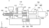
- FIG. 1 is an overall view of an electric injection molding machine according to a first embodiment.
- FIG. 1 shows a part of the electric injection molding machine 1 in cross section.
- the x-axis plus direction is the right direction of the page.
- the y-axis plus direction is the upward direction on the page.
- the z-axis plus direction is a front direction perpendicular to the paper surface.
- the electric injection molding machine 1 shown in FIG. 1 plasticizes resin pellets and injects the plasticized resin into a mold.
- the electric injection molding machine 1 includes a first motor 300 that drives the ball screw 200 coaxially with the ball screw 200, and the first motor 300 directly drives the ball screw 200. Further, the electric injection molding machine 1 has a structure in which the second motor 400 can be connected to the first motor 300.
- the electric injection molding machine 1 has a base 100, an injection device 110, a ball screw 200, a first motor 300, an encoder 500, and a control device 600 as main components.
- the base 100 is a casing composed of a plurality of metal plates or metal bars.
- a first fixed plate 101, a second fixed plate 102, and an injection device support portion 105 are erected on the upper surface of the base 100 (the surface on the y-axis plus side). These configurations standing on the base 100 are supported by the base 100.
- the first fixing plate 101 is a structure for fixing the first motor 300.
- the first motor 300 is fixed to the first fixing plate 101 by a fastening member such as a bolt.
- the first fixed plate 101 is made of a member that can suppress vibrations of the motor and the like. Such a member is, for example, iron or a metal containing iron as a main component.
- the first fixed plate 101 has a surface facing the second fixed plate 102, and a beam member 103 is erected on the surface.
- the first fixed plate 101 has a surface facing the injection device support portion 105, and a guide member 107 is erected on the surface.
- the second fixing plate 102 is a structure for fixing the second motor 400 connected to the first motor 300.
- the second fixed plate 102 is erected at a position where the first motor 300 and the second motor 400 can be connected. That is, in FIG. 1, the second fixed plate 102 is arranged in the order of the first fixed plate 101, the first motor 300, and the second fixed plate 102 along the x-axis plus direction.
- the second fixing plate 102 can fix the second motor 400 to the surface 102S opposite to the surface facing the first motor 300. Similar to the first fixed plate 101, the second fixed plate 102 is configured by a member that can suppress vibration of the motor and the like.
- the second fixed plate 102 has a beam member 103 erected on the surface facing the first fixed plate 101.
- the injection device support portion 105 is a structure that supports the cylinder 106 and the injection device 110.
- the cylinder 106 is mounted with a hopper 104, receives resin pellets from the hopper 104, and supplies the received resin pellets into the cylinder 106.
- the injection device support portion 105 has a surface facing the first fixed plate 101, and a guide member 107 is erected on the surface.
- the guide member 107 is a structure that bridges the first fixed plate 101 and the injection device support portion 105, and extends in the x-axis direction.
- the guide member 107 has a linear guide. The linear guide is engaged with the injection device 110, and the injection device 110 supports the x-axis so as to advance and retreat.
- the injection device 110 plasticizes the resin and injects the plasticized resin into the mold.
- the injection device 110 has a plasticizing motor 111.
- the power of the plasticizing motor 111 is transmitted to the screw 113 in the cylinder 106 via the belt 112.
- the screw 113 promotes plasticization of the resin and pushes the plasticized resin into a mold.
- the screw 113 is arranged such that the axial direction of the screw 113 is along the x axis, and the injection device 110 advances and retreats along the x axis.
- the injection device 110 is connected to the ball screw 200 and supported by a linear guide included in the guide member 107 so as to be able to advance and retract in the x-axis direction.
- the ball screw 200 is a ball screw having a rotation axis in a direction parallel to the x-axis, the x-axis plus side is connected to the first motor 300, and the x-axis minus side is connected to the injection device 110.
- the ball screw 200 receives a rotational driving force from the first motor 300, converts the received rotational driving force into a linear driving force, and uses the converted driving force to move the injection device 110 in the axial direction of the screw 113. Advance and retreat. That is, the ball screw 200 can be said to be a drive direction conversion unit having a mechanism for changing the drive direction.
- the first motor 300 is a motor that drives the ball screw 200 by being connected coaxially with the rotating shaft of the ball screw 200.
- the first motor 300 is fixed by the first fixing plate 101.
- the first motor 300 has a motor connecting portion 313 on the side opposite to the side connected to the ball screw 200.
- the motor connecting part 313 can be connected to the second motor 400 fixed to the second fixing plate 102.
- the second motor 400 can be fixed to the surface 102S of the second fixing plate 102. Further, the surface 102S has a structure that allows access to the motor connecting portion 313 of the first motor 300.
- the electric injection molding machine 1 according to the embodiment can connect the second motor 400 to the first motor 300 for driving the ball screw 200.
- the electric injection molding machine 1 according to the embodiment can drive the ball screw 200 by interlocking the first motor 300 and the second motor 400 connected to the first motor 300.
- the first motor 300 has an encoder 500.
- the encoder 500 is a device that detects the rotational speed of the first motor 300.
- the encoder 500 is, for example, a rotary encoder that includes a light emitting element and a light receiving element, a magnetic sensor using a Hall element, a coil, or the like.
- the second motor 400 may include an encoder 501. When the second motor 400 is connected to the first motor 300, the encoder 501 may supply the electric injection molding machine 1 with a signal regarding the rotation speed of the second motor 400 acquired by the encoder 501.
- the control device 600 is a device that controls the operation of the motor of the electric injection molding machine, and includes a substrate, a circuit, a microcomputer, and the like.
- the control device 600 includes a display unit 601 and an operation unit 602 as an interface for the user.
- the control device 600 can be installed at any location of the electric injection molding machine 1.
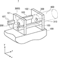
- FIG. 2 is a perspective view of a fixed plate of the electric injection molding machine according to the first embodiment.
- FIG. 2 shows a state in which a part of the electric injection molding machine 1 is cut out, and the ball screw 200, the first motor 300, and the connected second motor 400 are indicated by a two-dot chain line.
- the electric injection molding machine 1 includes a first fixing plate 101 that fixes a surface 300 ⁇ / b> S of the first motor 300 having a connecting portion with the ball screw 200.
- the electric injection molding machine 1 has a second fixing plate 102 for fixing the second motor 400 to the side of the first motor 300 having the motor connecting portion 313.
- the electric injection molding machine 1 has a beam member 103 that bridges the first fixed plate 101 and the second fixed plate 102.
- the beam member 103 extends in the x-axis direction so as to connect the first fixed plate 101 and the second fixed plate 102.
- the electric injection molding machine 1 has two such beam members 103 in the z-axis direction.
- a guide member 107 is erected on the x-axis minus side of the first fixed plate 101 and extends along the x-axis direction. As with the beam member 103, two guide members 107 are also provided in the z-axis direction.
- the guide member 107 extends in the x-axis direction and is connected to the injection device support portion 105. By connecting the guide member 107 to the first fixed plate 101 and the injection device support portion 105, the electric injection molding machine 1 increases the rigidity of the casing that supports the injection device 110 and the first motor 300.
- the electric injection molding machine 1 can improve the rigidity of the first fixed plate 101 and the second fixed plate 102 and suppress vibrations generated by the motor.
- the 1st fixing plate 101, the 2nd fixing plate 102, and the beam member 103 may be comprised by the integral member, and may be comprised by combining a some member.
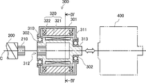
- FIG. 3 is a diagram for explaining the configuration of the motor according to the first embodiment.
- FIG. 4 is a cross-sectional view of the motor according to the first embodiment.
- FIG. 4 shows a cross section taken along line IV in FIG.
- the first motor 300 is a synchronous motor in which a rotor is rotated by a surrounding rotating magnetic field generated by an alternating current.
- An object of the present embodiment is to provide a motor with high torque and high acceleration in an electric injection molding machine. Therefore, the first motor 300 is preferably a synchronous motor.
- the first motor 300 includes, as main components, a rotor 310 that is a rotating shaft, a stator 320 disposed around the rotor 310, and a case 301 that supports the rotor 310 and the stator 320.
- the 1st motor 300 shown in FIG. 3 and FIG. 4 has shown the main structures, and has abbreviate
- the rotor 310 has a plurality of permanent magnets 311 for generating a rotational force according to a magnetic field generated by a coil of the stator 320.
- the rotor 310 has a drive connecting portion 312 for connecting the ball screw 200 at one end, and a motor connecting portion 313 for connecting the second motor 400 at the other end.
- the rotor 310 has a hollow structure.
- the rotor 310 is configured, for example, by laminating electromagnetic steel plates.
- the rotor 310 is supported by the case 301 via a bearing 302.
- the driving connecting portion 312 is fitted with the driven connecting portion 210 included in the ball screw 200.
- the drive connecting portion 312 and the driven connecting portion 210 are configured to be fixed without rattling when they are fitted, and to be interlocked around a common rotation axis C.
- the drive connecting portion 312 and the driven connecting portion 210 are in a male-female relationship and have a detent structure.
- the driven connection portion 210 is a spline-shaped shaft
- the drive connection portion 312 is a spline-shaped hole corresponding to the driven connection portion 210.
- the shape of the connecting portion is not limited to the spline shape, and may be serrations, D cuts, or the like.
- the motor connecting portion 313 has a shape for connecting to the second motor 400. That is, the motor connecting portion 313 is connected to the first motor 300 coaxially with the ball screw 200 and connects the second motor 400 that drives the ball screw 200 in conjunction with the first motor 300. Further, the motor connecting portion 313 has a structure capable of separating the second motor 400 again after connecting the second motor 400. In other words, the second motor 400 can be attached to and detached from the electric injection molding machine 1.
- the motor connecting portion 313 may have the same shape as the driven connecting portion 210 of the ball screw 200, for example.
- the first motor 300 has a drive connection portion 312 at one end of the rotor 310 and a motor connection portion 313 that has a shape that can be fitted to the drive connection portion 312 at the other end.
- the first motors 300 can be connected to each other.
- the first motor 300 and the second motor 400 may be the same.
- the stator 320 is provided around the rotor, and has a plurality of teeth 321 and a coil 322 wound around the plurality of teeth 321.
- the teeth 321 are configured by laminating electromagnetic steel plates, for example.
- the coil 322 is configured by winding a plurality of conductive wires, for example.
- the first motor 300 shown in FIGS. 3 and 4 is an example of a synchronous motor. That is, in the first motor according to the embodiment, the number of magnets included in the rotor, the number of teeth included in the stator, the coil winding specifications, the number of coil phases, and the like are various.
- the first motor 300 may be a reluctance motor that does not incorporate a magnet in the rotor.
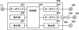
- FIG. 5 is a block diagram of the control device according to the first embodiment.
- the control device 600 includes a display unit 601, an operation unit 602, a servo amplifier 603, a control unit 604, a servo amplifier 605, a servo amplifier 606, a detection unit 607, and a connector 608.
- the electric injection molding machine 1 may include a mold clamping unit (not shown) that opens and closes the mold and a temperature control device (not shown) that controls the temperature of the resin and the mold.
- a mold clamping unit and a temperature control device are generally configured by a widely known technique. Therefore, in the present disclosure, these descriptions are omitted.
- the control device 600 may have a function of controlling these omitted configurations.
- the display unit 601 is a liquid crystal display device including a display controller, for example, and displays information when the user performs various operations.
- the operation unit 602 is an input device for a user to perform various input operations, and is, for example, a button or a touch panel.
- the display unit 601 and the operation unit 602 are connected to the control unit 604, and input various signals or output information via the control unit 604.
- the servo amplifier 603 receives an instruction from the control unit 604 and outputs a current for operating the plasticizing motor 111 based on the received instruction.
- the control unit 604 is connected to each component of the control device 600 and controls the operation of the electric injection molding machine 1.
- the control unit 604 includes, for example, a substrate on which a CPU (Central Processing Unit) and a memory are mounted.
- the control unit 604 sends an instruction for interlocking to the servo amplifier 605 and the servo amplifier 606. Accordingly, the first motor 300 and the second motor 400 drive the ball screw 200 in conjunction with each other.
- Servo amplifier 605 receives an instruction from control unit 604 and outputs a current for operating first motor 300 based on the received instruction.
- the servo amplifier 606 receives an instruction from the control unit 604, and outputs a current for operating the second motor 400 based on the received instruction.
- the servo amplifier 606 is connected to the connector 608.
- the connector 608 can be detachably connected to the connector 430.
- the connector 430 is connected to the second motor 400.
- the detection unit 607 is connected to the encoder 500 and supplies data related to the rotation of the first motor detected by the encoder 500 to the control unit 604.
- the encoder 500 may be connected to the servo amplifier 605 or the servo amplifier 606 via the control unit 604, or may be directly connected to the servo amplifier 605 and the servo amplifier 606 without going through the control unit 604.
- FIG. 6 is a block diagram of another example of the control device according to the first embodiment.
- the example illustrated in FIG. 6 is different from the control device 600 illustrated in FIG. 5 in that the servo amplifier 605 that operates the first motor 300 has a function of operating the second motor 400.
- the control device 600 can synchronize the first motor 300 and the second motor 400 with one servo amplifier. 5 and 6, the second motor 400 may include the encoder 501 illustrated in FIG. 1.
- the control device 600 can control the first motor 300 and the second motor 400 using at least one or both of the signals received from the encoder 500 and the encoder 501.
- control unit 604 may be connected to the encoder 501 and control the first motor 300 and the second motor 400 based on the signal from the encoder 501.
- control unit 604 acquires both the signals of the encoder 500 and the encoder 501, generates a combined signal from the acquired signals by a method set in advance, and based on the generated combined signal, the first motor 300 and the first Two motors 400 may be controlled.
- the preset method is, for example, synthesis by sum, product, or average of signals.
- the electric injection molding machine 1 can be connected to the second motor 400 that drives the ball screw 200 in conjunction with the first motor 300. Thereby, the electric injection molding machine 1 can set suitably the torque and responsiveness which drive the ball screw 200.
- FIG. That is, according to the first embodiment, it is possible to provide an electric injection molding machine having a high degree of freedom in design and having a motor with high torque and low inertia.
- the second embodiment is different from the first embodiment in that the second motor 400 is connected.
- FIG. 7 is an overall view of the electric injection molding machine 2 according to the second embodiment.
- the electric injection molding machine 2 includes a second motor 400 and an encoder 500 in addition to the electric injection molding machine 1 according to the first embodiment.
- the second motor 400 is fixed on the surface 102 ⁇ / b> S of the second fixed plate 102. That is, the electric injection molding machine 2 includes a first fixed plate 101 for fixing the first motor 300 and a second fixed plate 102 for fixing the second motor 400.
- the electric injection molding machine 2 includes a beam member 103 that bridges the first fixed plate 101 and the second fixed plate 102.
- the first motor 300 and the second motor 400 may be collectively referred to as a driving device 700.
- the driving device 700 includes a plurality of motors, and the plurality of motors drive the ball screw 200 in conjunction with each other.
- the encoder 500 is directly or indirectly engaged with a rotor included in the motor, and detects the number of rotor rotations to be engaged.
- FIG. 8 is a diagram for explaining the configuration of the driving apparatus according to the second embodiment.
- the driving device 700 has a first motor 300 and a second motor 400.
- An object of the present embodiment is to provide a motor with high torque and high acceleration in an electric injection molding machine. Therefore, the first motor 300 and the second motor 400 are preferably synchronous motors in which the rotor is rotated by the surrounding rotating magnetic field generated by the alternating current.
- the first motor 300 has the same configuration as that described with reference to FIG.
- the second motor 400 has the same configuration as the first motor 300. That is, the second motor 400 is a PM motor, and has a rotor 410, a stator 420, and a case 401 as main components.
- the first motor 300 and the second motor 400 have the same number of magnet poles and the same iron core thickness.
- the first motor 300 and the second motor 400 have the same number of coil phases and the same number of slots.
- the first motor 300 and the second motor 400 may be an SPM motor that incorporates a magnet on the rotor surface or an IPM motor that incorporates a magnet inside the rotor. Further, the first motor 300 and the second motor 400 may be a reluctance motor in which no magnet is incorporated in the rotor.
- the motor connecting portion 313 included in the first motor is connected to the drive connecting portion 412 included in the second motor 400. Further, the drive connection portion 312 of the rotor 310 is connected to the driven connection portion 210 of the ball screw 200. Therefore, the rotor 310 and the rotor 410 are coaxially connected to the rotation axis C of the ball screw 200 and drive the ball screw 200 in conjunction with each other.
- the second motor 400 has a motor connecting portion 413 on the side opposite to the drive connecting portion 412 connected to the first motor 300.
- the encoder 500 is connected to the motor connecting portion 413.
- the encoder 500 detects data related to the rotational speed of the drive device 700 and supplies the detected data related to the rotational speed to the servo amplifier of the drive device 700. That is, the servo amplifier of the driving device 700 shares the signal received from the encoder 500 when controlling the first motor 300 and the second motor 400, respectively.
- the control device 600 controls a plurality of motors included in the drive device 700 using signals received from the encoder 500.
- the control device 600 included in the electric injection molding machine 2 drives the first motor 300 and the second motor 400 by synchronizing the currents applied to the coil 322 of the first motor 300 and the coil 422 of the second motor 400.
- the number of motors included in the driving device 700 is not limited to two. That is, the driving device 700 has three or more motors, and the three or more motors are coaxially connected to the rotation axis C of the ball screw 200 and drive the ball screw 200 in conjunction with each other. Also good.
- the electric injection molding machine 2 has a plurality of fixing plates for fixing a plurality of motors, and one fixing plate has a configuration for fixing one motor.
- the electric injection molding machine 2 may have a beam member that bridges the plurality of fixing plates.
- the electric injection molding machine 2 includes the drive device 700 having a plurality of motors. Thereby, the electric injection molding machine 2 can set suitably the torque and responsiveness which drive the ball screw 200.
- FIG. That is, according to the second embodiment, it is possible to provide an electric injection molding machine having a motor with a high degree of design freedom and a high torque and low inertia.
Landscapes
- Engineering & Computer Science (AREA)
- Manufacturing & Machinery (AREA)
- Mechanical Engineering (AREA)
- Power Engineering (AREA)
- Injection Moulding Of Plastics Or The Like (AREA)
Abstract
電動射出成形機(1)は、樹脂を射出するためのスクリュ(113)を含む射出装置(110)と、射出装置(110)をスクリュ(113)のアキシャル方向に進退させる駆動方向変換部と、駆動方向変換部の回転軸と同軸上に連結して駆動方向変換部を駆動する第1モータ(300)と、を備える。第1モータ(300)は、駆動方向変換部と連結している側とは反対の側において、第1モータ(300)に対して駆動方向変換部と同軸上に連結し、第1モータ(300)と連動して駆動方向変換部を駆動する第2モータ(400)を連結するためのモータ連結部(313)を有する。
Description
本発明は電動射出成形機に関する。
近年、電動射出成形機に対して薄肉成形品への対応能力向上が期待されている。この要求に応えるためには、電動射出成形機が樹脂を高速で金型に注入する必要がある。樹脂を高速で金型に注入する技術の1つとして、例えば高トルクかつ低イナーシャで駆動するモータの開発が挙げられる。かかるモータは、樹脂を射出するためのスクリュを高加速かつ高速で移動させることに寄与し得る。かかるモータの技術について、種々の提案が行われている。
特許文献1に記載の電動射出成形機は、スクリュを備えた射出装置、可動プラテンを備えた型締装置、およびエジェクタピンを備えたエジェクタ装置を有する。かかる電動射出成形機は、各電動機のうちの少なくとも一つの電動機において、ステータの内径に対するロータの磁石の積層長さの比が3以上にされることを特徴とする。
特許文献2に記載のリラクタンスモータは、3個のモータ単体が1本の回転軸を共用する。
特許文献1に記載の電動射出成形機は、1つのモータが長尺となるため、ロータ、ステータ、およびその他の各部品の機械加工について求められる加工精度が高まり、ひいてはコストの増大につながるおそれがある。また、特許文献2に記載のリラクタンスモータは1本の回転軸を共用するものであり設計自由度が低い。そこで、上述のような設計制約を受けることなく、スクリュを高加速かつ高速で移動させるモータの実現が望まれる。
その他の課題と新規な特徴は、本明細書の記述および添付図面から明らかになるであろう。
一実施の形態にかかる電動射出成形機は、樹脂を射出するためのスクリュを含む射出装置と、前記射出装置を前記スクリュのアキシャル方向に進退させる駆動方向変換部と、前記駆動方向変換部の回転軸と同軸上に連結して前記駆動方向変換部を駆動する第1モータと、を備える。そして、前記第1モータは、前記駆動方向変換部と連結している側とは反対の側において、前記第1モータに対して前記駆動方向変換部と同軸上に連結し、前記第1モータと連動して前記駆動方向変換部を駆動する第2モータを連結するためのモータ連結部を有する。
また、一実施の形態にかかる電動射出成形機は、樹脂を射出するためのスクリュを含む射出装置と、前記射出装置を前記スクリュのアキシャル方向に進退させる駆動方向変換部と、前記駆動方向変換部を駆動するための駆動装置と、を備える。そして、前記駆動装置は、複数のモータを有し、前記複数のモータがそれぞれ有するロータは、前記駆動方向変換部の回転軸と同軸上に連結し、連動して前記駆動方向変換部を駆動する。
前記一実施の形態によれば、設計自由度が高く、かつ、高トルク低イナーシャのモータを有する電動射出成形機を提供することができる。
以下、図面を参照しつつ、実施の形態について説明する。なお、図面は簡略的なものであるから、この図面の記載を根拠として実施の形態の技術的範囲を狭く解釈してはならない。また、同一の要素には、同一の符号を付し、重複する説明は省略する。
以下の実施の形態においては便宜上その必要があるときは、複数のセクション又は実施の形態に分割して説明するが、特に明示した場合を除き、それらはお互いに無関係なものではなく、一方は他方の一部又は全部の変形例、応用例、詳細説明、補足説明等の関係にある。また、以下の実施の形態において、要素の数等(個数、数値、量、範囲等を含む)に言及する場合、特に明示した場合および原理的に明らかに特定の数に限定される場合等を除き、その特定の数に限定されるものではなく、特定の数以上でも以下でもよい。
さらに、以下の実施の形態において、その構成要素(動作ステップ等も含む)は、特に明示した場合および原理的に明らかに必須であると考えられる場合等を除き、必ずしも必須のものではない。同様に、以下の実施の形態において、構成要素等の形状、位置関係等に言及するときは、特に明示した場合および原理的に明らかにそうでないと考えられる場合等を除き、実質的にその形状等に近似又は類似するもの等を含むものとする。このことは、上記数等(個数、数値、量、範囲等を含む)についても同様である。
<実施の形態1>
以下、図面を参照して実施の形態1について説明する。
図1は、実施の形態1にかかる電動射出成形機の全体図である。なお、説明の便宜上、図1は、電動射出成形機1の一部を断面で表示している。また、理解を容易にするため、図1において右手系xyz座標を示している。x軸プラス方向は紙面の右方向である。y軸プラス方向は、紙面の上方向である。z軸プラス方向は、紙面に対して鉛直の手前方向である。
以下、図面を参照して実施の形態1について説明する。
図1は、実施の形態1にかかる電動射出成形機の全体図である。なお、説明の便宜上、図1は、電動射出成形機1の一部を断面で表示している。また、理解を容易にするため、図1において右手系xyz座標を示している。x軸プラス方向は紙面の右方向である。y軸プラス方向は、紙面の上方向である。z軸プラス方向は、紙面に対して鉛直の手前方向である。
図1に示す電動射出成形機1は、樹脂ペレットを可塑化し、可塑化した樹脂を金型に注入する。電動射出成形機1は、ボールねじ200と同軸上にボールねじ200を駆動する第1モータ300を配置し、第1モータ300がボールねじ200を直接駆動する方式を有している。また、電動射出成形機1は、第1モータ300に第2モータ400を連結可能な構造となっている。電動射出成形機1は主な構成として、基台100、射出装置110、ボールねじ200、第1モータ300、エンコーダ500、および制御装置600を有している。
基台100は、複数の金属板材又は金属棒材などにより構成される躯体である。基台100の上面(y軸プラス側の面)には、第1固定プレート101、第2固定プレート102、射出装置支持部105がそれぞれ立設されている。基台100に立設されるこれらの構成は、基台100により支持されている。
第1固定プレート101は、第1モータ300を固定するための構造体である。第1モータ300は、例えばボルトなどの締結部材によって第1固定プレート101に固定される。第1固定プレート101は、モータの振動等を抑えることができるような部材により構成される。かかる部材は、例えば、鉄又は鉄を主成分とする金属等である。第1固定プレート101は、第2固定プレート102と対向する面を有し、かかる面に梁部材103が立設されている。また、第1固定プレート101は、射出装置支持部105と対向する面を有し、かかる面にガイド部材107が立設されている。
第2固定プレート102は、第1モータ300に連結する第2モータ400を固定するための構造体である。第2固定プレート102は、第1モータ300と第2モータ400とを連結させ得る位置に立設されている。すなわち、図1において、第2固定プレート102はx軸プラス方向に沿って、第1固定プレート101、第1モータ300、そして第2固定プレート102の順に配置されている。第2固定プレート102は第1モータ300に対向する面の反対側の面102Sに第2モータ400を固定し得る。第2固定プレート102は、第1固定プレート101と同様に、モータの振動等を抑えることができるような部材により構成される。また、第2固定プレート102は、第1固定プレート101と対向する面に梁部材103が立設されている。
射出装置支持部105は、シリンダ106および射出装置110を支持する構造体である。シリンダ106は、ホッパ104を搭載し、ホッパ104から樹脂ペレットを受け取り、受け取った樹脂ペレットをシリンダ106内に供給する。また、射出装置支持部105は、第1固定プレート101と対向する面を有し、かかる面にガイド部材107が立設されている。ガイド部材107は、第1固定プレート101と射出装置支持部105とを橋架する構造体であって、x軸方向に延伸している。また、ガイド部材107は、リニアガイドを有している。かかるリニアガイドは、射出装置110と係合しており、射出装置110がx軸に進退可能に支持している。
射出装置110は、樹脂を可塑化し、可塑化した樹脂を金型に注入する。射出装置110は、可塑化モータ111を有している。可塑化モータ111の動力はベルト112を介してシリンダ106内のスクリュ113に伝えられる。スクリュ113は樹脂の可塑化を促進させるとともに、可塑化した樹脂を金型に押し出す。図1において、スクリュ113はスクリュ113のアキシャル方向がx軸に沿って配置されており、射出装置110は、x軸に沿って進退する。射出装置110は、ボールねじ200に連結すると共に、ガイド部材107が有しているリニアガイドによりx軸方向に進退可能に支持されている。
ボールねじ200は、x軸に平行な方向に回転軸を有するボールねじであり、x軸プラス側が第1モータ300に連結し、x軸マイナス側が射出装置110に連結している。ボールねじ200は、第1モータ300から回転方向の駆動力を受け、受けた回転方向の駆動力を直線方向の駆動力に変換し、変換した駆動力により射出装置110をスクリュ113のアキシャル方向に進退させる。すなわち、ボールねじ200は、駆動方向を変換する機構を有する駆動方向変換部ということができる。
第1モータ300は、ボールねじ200の回転軸と同軸上に連結してボールねじ200を駆動するモータである。第1モータ300は、第1固定プレート101により固定されている。第1モータ300は、ボールねじ200と連結している側とは反対の側に、モータ連結部313を有している。モータ連結部313は、第2固定プレート102に固定される第2モータ400と連結し得る。第2固定プレート102の面102Sは、第2モータ400が固定され得る。また、面102Sは、第1モータ300が有するモータ連結部313にアクセス可能な構造になっている。このような構造により、実施の形態にかかる電動射出成形機1は、ボールねじ200を駆動するための第1モータ300に第2モータ400を連結させることができる。また、実施の形態にかかる電動射出成形機1は、第1モータ300と第1モータ300に連結した第2モータ400とを連動させてボールねじ200を駆動することができる。
第1モータ300は、エンコーダ500を有している。エンコーダ500は、第1モータ300の回転速度を検出する装置である。エンコーダ500は例えば発光素子および受光素子を含むものや、ホール素子やコイル等を利用した磁気式センサによって構成されるロータリーエンコーダ等である。なお、第2モータ400は、エンコーダ501を有していてもよい。第2モータ400が第1モータ300に連結した場合、エンコーダ501は、エンコーダ501が取得する第2モータ400の回転数に関する信号を、電動射出成形機1に供給してもよい。
制御装置600は、電動射出成形機が有するモータの動作を制御する装置であり、基板、回路、マイコン等を含む。制御装置600は、使用者に対するインタフェイスとして表示部601および操作部602を有している。制御装置600は、電動射出成形機1の任意の場所に設置され得る。
次に、図2を参照しながら、電動射出成形機1が有する第1固定プレート101および第2固定プレート102の構造について説明する。図2は、実施の形態1にかかる電動射出成形機の固定プレートの斜視図である。図2は、電動射出成形機1の一部を切り出した状態であり、ボールねじ200、第1モータ300、および連結された第2モータ400を二点鎖線により示している。
図2に示すように、電動射出成形機1は、第1モータ300の、ボールねじ200との連結部を有する面300Sを固定する第1固定プレート101を有している。また、電動射出成形機1は、第1モータ300のモータ連結部313を有する側に前記第2モータ400を固定するための第2固定プレート102を有している。
電動射出成形機1は、第1固定プレート101と第2固定プレート102とを橋架する梁部材103を有している。梁部材103は、第1固定プレート101と第2固定プレート102を繋ぐように、x軸方向に延伸している。また、電動射出成形機1は、かかる梁部材103をz軸方向に2つ有している。また、第1固定プレート101のx軸マイナス側には、ガイド部材107が立設されており、x軸方向に沿って延伸している。ガイド部材107も、梁部材103と同様に、z軸方向に2つ設けられている。ガイド部材107は、x軸方向に延伸し、射出装置支持部105に繋がっている。ガイド部材107が第1固定プレート101と射出装置支持部105とに繋がることにより、電動射出成形機1は、射出装置110および第1モータ300を支持する躯体の剛性を高めている。
このような構成により、実施の形態に係る電動射出成形機1は、第1固定プレート101および第2固定プレート102の剛性が互いに向上し、モータが発生させる振動を抑制することができる。なお、第1固定プレート101、第2固定プレート102、および梁部材103は一体の部材により構成されていてもよいし、複数の部材を組み合わせることにより構成されてもよい。
次に、図3および図4を参照しながら第1モータ300の構造の一例について説明する。図3は、実施の形態1にかかるモータの構成を説明するための図である。図4は、実施の形態1にかかるモータの断面図である。図4は図3における線分IVにおける断面を示している。
第1モータ300は、交流電流が作る周囲の回転磁界によってロータが回転する、同期モータである。本実施の形態においては、電動射出成形機において高トルク且つ高加速のモータを提供することを目的としている。したがって、第1モータ300は、同期モータであることが好ましい。図3および図4に例示した第1モータ300は、ロータ310に永久磁石を有するPMモータ(PM= Permanent Magnet)である。第1モータ300は、主な構成として、回転軸であるロータ310と、ロータ310の周囲に配置されたステータ320と、ロータ310およびステータ320を支持するケース301と、を有している。なお、図3および図4に示す第1モータ300は、主な構成を示しており、より詳細な構成については適宜省略している。これら詳細については当業者が当然に知るところである。
ロータ310は、ステータ320が有するコイルが発生する磁界に応じて回転力を発生させるための複数の永久磁石311を有している。また、ロータ310は、一端にボールねじ200を連結するための駆動連結部312を有し、他端に第2モータ400を連結するためのモータ連結部313を有している。また、ロータ310は、中空構造を呈している。ロータ310は、例えば、電磁鋼板を積層させることにより構成されている。ロータ310は、軸受302を介して、ケース301に支持されている。
駆動連結部312は、ボールねじ200が有する被駆動連結部210と嵌合する。駆動連結部312と被駆動連結部210とは、嵌合するとガタツキなく固定され、共通する回転軸Cを中心として連動するように構成されている。駆動連結部312と被駆動連結部210とは、互いに雄雌の関係であって、かつ、回り止め構造を有している。図3の例においては、被駆動連結部210がスプライン形状の軸であり、駆動連結部312が被駆動連結部210に対応したスプライン形状の穴である。なお、連結部の形状は、スプライン形状に限らず、セレーションやDカット等であってもよい。
モータ連結部313は、第2モータ400に連結するための形状を呈している。すなわちモータ連結部313は、第1モータ300に対してボールねじ200と同軸上に連結し、第1モータ300と連動してボールねじ200を駆動する第2モータ400を連結する。また、モータ連結部313は、第2モータ400を連結した後に第2モータ400を再び分離可能な構造を有している。つまり、電動射出成形機1は、第2モータ400が着脱可能である。
モータ連結部313は、例えば、ボールねじ200の被駆動連結部210と同じ形状であってもよい。この場合、第1モータ300は、ロータ310の一端に駆動連結部312を有し、他端に駆動連結部312に対して嵌合し得る形状を呈するモータ連結部313を有する。このような構造を採用することにより、第1モータ300は、互いに連結することが可能な構造となる。この場合、第1モータ300と第2モータ400とは同じものであってもよい。
ステータ320は、ロータを周囲に設けられ、複数のティース321と、かかる複数のティース321に巻回されたコイル322とを有している。ティース321は、例えば電磁鋼板を積層することにより構成される。また、コイル322は、例えば導線を複数巻回することにより構成される。
なお、図3および図4において示した第1モータ300は、同期モータの一例である。すなわち、実施の形態にかかる第1モータにおいて、ロータが有する磁石の数、ステータが有するティースの数、コイルの巻回の仕様、またコイルの相数などは様々である。また、第1モータ300は、磁石をロータ表面に組み込むSPMモータ(SPM=Surface Permanent Magnet)であっても、磁石をロータ内部に組み込むIPMモータ(IPM=Interior permanent Magnet)であってもよい。また、第1モータ300は、ロータに磁石を組み込んでいないリラクタンスモータであってもよい。
次に、図5を参照しながら、制御装置600について説明する。図5は、実施の形態1にかかる制御装置のブロック図である。制御装置600は、表示部601、操作部602、サーボアンプ603、制御部604、サーボアンプ605、サーボアンプ606、検出部607、およびコネクタ608を有している。なお、電動射出成形機1は、金型を開閉する型締めユニット(不図示)や、樹脂や金型の温度を制御する温度制御装置(不図示)を含み得る。本実施の形態において、かかる型締めユニットや温度制御装置は、一般に広く知られた技術により構成されている。そのため、本開示において、これらの説明は省略する。制御装置600は、省略されたこれらの構成を制御する機能を有していてもよい。
表示部601は、例えば表示コントローラを含む液晶表示装置であり、使用者が種々の操作を行う際の情報を表示する。操作部602は、使用者が種々の入力操作をするための入力装置であって、例えば、ボタンやタッチパネル等である。表示部601および操作部602は、制御部604に接続し、制御部604を介して種々の信号の入力又は情報の出力を行う。
サーボアンプ603は、制御部604からの指示を受け取り、受け取った指示に基づいて、可塑化モータ111を動作するための電流を出力する。
制御部604は、制御装置600の各構成に接続し、電動射出成形機1の動作を制御する。制御部604は、例えば、CPU(Central Processing Unit)やメモリが実装された基板を含む。電動射出成形機1に第2モータ400が接続された場合、制御部604は、サーボアンプ605およびサーボアンプ606に対して、連動させるための指示を送る。これにより第1モータ300および第2モータ400は、連動してボールねじ200を駆動する。
サーボアンプ605は、制御部604からの指示を受け取り、受け取った指示に基づいて、第1モータ300を動作するための電流を出力する。
サーボアンプ606は、制御部604からの指示を受け取り、受け取った指示に基づいて、第2モータ400を動作するための電流を出力する。サーボアンプ606はコネクタ608に接続している。コネクタ608は、コネクタ430と着脱可能に接続し得る。コネクタ430は、第2モータ400に接続している。
検出部607は、エンコーダ500に接続し、エンコーダ500が検出した第1モータの回転に関するデータを制御部604に供給する。なお、エンコーダ500は、制御部604を介してサーボアンプ605又はサーボアンプ606に接続してもよいし、制御部604を介さず、直接サーボアンプ605およびサーボアンプ606に接続してもよい。
次に、図6を参照しながら、制御装置600の別の例について説明する。図6は、実施の形態1にかかる制御装置のもう一つの例を示すブロック図である。図6に示す例は、第1モータ300を動作させるサーボアンプ605が、第2モータ400も動作させる機能を有する点において、図5に例示した制御装置600と異なる。このような構成にすることにより、制御装置600は、第1モータ300および第2モータ400を1つのサーボアンプにより同期して連動させることができる。なお、図5および図6において、第2モータ400は、図1に図示したエンコーダ501を有していてもよい。この場合、制御装置600は、エンコーダ500又はエンコーダ501から受ける信号の少なくともいずれか一方又はその両方を利用して、第1モータ300および第2モータ400を制御しうる。すなわち、制御部604は、エンコーダ501に接続し、エンコーダ501の信号に基づいて第1モータ300および第2モータ400を制御してもよい。また、制御部604は、エンコーダ500およびエンコーダ501の信号をいずれも取得し、取得した信号を予め設定された方法により合成信号を生成し、生成した合成信号に基づいて、第1モータ300および第2モータ400を制御してもよい。ここで、予め設定された方法とは、例えば、信号の和、積、平均による合成などである。
以上に説明したように、実施の形態1にかかる電動射出成形機1は、第1モータ300に連動してボールねじ200を駆動する第2モータ400を連結可能である。これにより、電動射出成形機1は、ボールねじ200を駆動するトルクや応答性を好適に設定することが可能である。すなわち、実施の形態1により、設計自由度が高く、かつ、高トルク低イナーシャのモータを有する電動射出成形機を提供することができる。
<実施の形態2>
次に、実施の形態2について説明する。実施の形態2は、第2モータ400が連結した状態である点において、実施の形態1と異なる。
次に、実施の形態2について説明する。実施の形態2は、第2モータ400が連結した状態である点において、実施の形態1と異なる。
まず、図7を参照しながら、第1モータ300と第2モータ400とを連結した場合について説明する。図7は、実施の形態2にかかる電動射出成形機2の全体図である。
図7において、電動射出成形機2は、実施の形態1にかかる電動射出成形機1に加えて、第2モータ400、およびエンコーダ500を有している。第2モータ400は、第2固定プレート102の面102Sにおいて固定されている。すなわち、電動射出成形機2は、第1モータ300を固定するための第1固定プレート101と、第2モータ400を固定するための第2固定プレート102を有している。また、電動射出成形機2は、第1固定プレート101と第2固定プレート102とを橋架する梁部材103を有している。
電動射出成形機2において、第1モータ300および第2モータ400を併せて駆動装置700と称することもできる。駆動装置700は、複数のモータを有し、かかる複数のモータが連動してボールねじ200を駆動する。エンコーダ500は、モータが有するロータに直接又は間接に係合し、係合するロータ回転数を検出する。
次に、図8を参照しながら駆動装置700の構成について説明する。図8は、実施の形態2にかかる駆動装置の構成を説明するための図である。
駆動装置700は、第1モータ300および第2モータ400を有している。本実施の形態においては、電動射出成形機において高トルク且つ高加速のモータを提供することを目的としている。したがって、第1モータ300および第2モータ400は、交流電流が作る周囲の回転磁界によってロータが回転する、同期モータであることが好ましい。第1モータ300は、図3を参照しながら説明したものと同じ構成を有している。また、第2モータ400は、第1モータ300と同様の構成を有している。すなわち、第2モータ400は、PMモータであり、主な構成として、ロータ410、ステータ420、ケース401を有している。第1モータ300と第2モータ400とは、ロータが有する磁石の極数、および鉄心の積厚がそれぞれ同じである。また、第1モータ300と第2モータ400とは、コイルの相数およびスロット数がそれぞれ同じである。なお、第1モータ300はと第2モータ400とは、磁石をロータ表面に組み込むSPMモータであっても、磁石をロータ内部に組み込むIPMモータであってもよい。また、第1モータ300と第2モータ400とは、ロータに磁石を組み込んでいないリラクタンスモータであってもよい。
第1モータが有するモータ連結部313は、第2モータ400が有する駆動連結部412と連結している。また、ロータ310の駆動連結部312は、ボールねじ200の被駆動連結部210と連結している。したがって、ロータ310およびロータ410は、ボールねじ200の回転軸Cと同軸上に連結し、連動してボールねじ200を駆動する。
第2モータ400は、第1モータ300と連結している駆動連結部412とは反対の側に、モータ連結部413を有している。モータ連結部413には、エンコーダ500が連結している。エンコーダ500は、駆動装置700の回転速度に関するデータを検出し、検出した回転数に関するデータを駆動装置700のサーボアンプに供給する。すなわち、駆動装置700のサーボアンプは、第1モータ300と第2モータ400とをそれぞれ制御する際に、エンコーダ500から受け取る信号を共用する。換言すると、制御装置600は、エンコーダ500から受け取る信号を利用して駆動装置700が有する複数のモータを制御する。電動射出成形機2が有する制御装置600は、第1モータ300のコイル322および第2モータ400のコイル422に印加する電流を同期させて、第1モータ300および第2モータ400を駆動する。
なお、駆動装置700が有するモータは2つに限られない。すなわち、駆動装置700は、3つ以上のモータを有し、かかる3つ以上のモータがボールねじ200の回転軸Cと同軸上に連結し、連動してボールねじ200を駆動する構成であってもよい。その場合、電動射出成形機2は、複数のモータを固定するための複数の固定プレートを有し、一の固定プレートは、一のモータをそれぞれ固定する構成を有する。さらに、電動射出成形機2は、かかる複数の固定プレートを橋架する梁部材を有し得る。
以上に説明したように、実施の形態2にかかる電動射出成形機2は、複数のモータを有する駆動装置700を有する。これにより、電動射出成形機2は、ボールねじ200を駆動するトルクや応答性を好適に設定することが可能である。すなわち、実施の形態2により、設計自由度が高く、かつ、高トルク低イナーシャのモータを有する電動射出成形機を提供することができる。
なお、本発明は上記実施の形態に限られたものではなく、趣旨を逸脱しない範囲で適宜変更することが可能である。
この出願は、2018年2月28日に出願された日本出願特願2018-034582を基礎とする優先権を主張し、その開示の全てをここに取り込む。
1、2 電動射出成形機
100 基台
101 第1固定プレート
102 第2固定プレート
103 梁部材
104 ホッパ
105 射出装置支持部
106 シリンダ
107 ガイド部材
110 射出装置
111 可塑化モータ
112 ベルト
113 スクリュ
210 被駆動連結部
300 第1モータ
301、401 ケース
302 軸受
310、410 ロータ
311、411 永久磁石
312、412 駆動連結部
313、413 モータ連結部
320、420 ステータ
321、421 ティース
322、422 コイル
400 第2モータ
430 コネクタ
500、501 エンコーダ
600 制御装置
601 表示部
602 操作部
603 サーボアンプ
604 制御部
605 サーボアンプ
606 サーボアンプ
607 検出部
608 コネクタ
700 駆動装置
100 基台
101 第1固定プレート
102 第2固定プレート
103 梁部材
104 ホッパ
105 射出装置支持部
106 シリンダ
107 ガイド部材
110 射出装置
111 可塑化モータ
112 ベルト
113 スクリュ
210 被駆動連結部
300 第1モータ
301、401 ケース
302 軸受
310、410 ロータ
311、411 永久磁石
312、412 駆動連結部
313、413 モータ連結部
320、420 ステータ
321、421 ティース
322、422 コイル
400 第2モータ
430 コネクタ
500、501 エンコーダ
600 制御装置
601 表示部
602 操作部
603 サーボアンプ
604 制御部
605 サーボアンプ
606 サーボアンプ
607 検出部
608 コネクタ
700 駆動装置
Claims (13)
- 樹脂を射出するためのスクリュを含む射出装置と、前記射出装置を前記スクリュのアキシャル方向に進退させる駆動方向変換部と、前記駆動方向変換部の回転軸と同軸上に連結して前記駆動方向変換部を駆動する第1モータと、を備え、
前記第1モータは、
前記駆動方向変換部と連結している側とは反対の側において、前記回転軸と同軸上に連結し、前記第1モータと連動して前記駆動方向変換部を駆動する第2モータを連結するためのモータ連結部を有する、
電動射出成形機。 - 前記モータ連結部は、前記第2モータを連結した後に前記第2モータを再び分離可能な構造を有する、
請求項1に記載の電動射出成形機。 - 前記第1モータの前記駆動方向変換部との連結部を有する面を固定する第1固定プレートを有し、
前記第1モータの前記モータ連結部を有する側に前記第2モータを固定するための第2固定プレートを有する、
請求項1に記載の電動射出成形機。 - 前記第1固定プレートと前記第2固定プレートとを橋架する梁部材を有する、
請求項3に記載の電動射出成形機。 - 前記第1モータを駆動させるサーボアンプを含む制御装置をさらに有し、
前記制御装置は、
前記第1モータと前記第2モータとを連動して駆動させるための第2モータ駆動用コネクタを有する、
請求項1~4のいずれか一項に記載の電動射出成形機。 - 前記第1モータの回転数又は前記第2モータの回転数を検出するエンコーダをさらに有し、
前記制御装置は、前記エンコーダから受け取る信号を利用して前記第1モータと前記第2モータとを制御する、
請求項5に記載の電動射出成形機。 - 樹脂を射出するためのスクリュを含む射出装置と、前記射出装置を前記スクリュのアキシャル方向に進退させる駆動方向変換部と、前記駆動方向変換部を駆動するための駆動装置と、
を備える電動射出成形機であって、
前記駆動装置は、複数のモータを有し、
前記複数のモータがそれぞれ有するロータは、前記駆動方向変換部の回転軸と同軸上に連結し、連動して前記駆動方向変換部を駆動する、
電動射出成形機。 - 前記複数のモータを固定するための複数の固定プレートをさらに有し、
一の前記固定プレートは、一の前記モータをそれぞれ固定する、
請求項7に記載の電動射出成形機。 - 前記複数の固定プレートを橋架する梁部材を有する、
請求項8に記載の電動射出成形機。 - 前記複数のモータは、ロータと、前記ロータの周囲に複数の巻回されたコイルと、を有する同期モータである、
請求項7~9のいずれか一項に記載の電動射出成形機。 - 前記複数のモータは、前記ロータが有する極数および鉄心の積厚がそれぞれ同じであって、かつ、前記コイルの相数およびスロット数がそれぞれ同じである、
請求項10に記載の電動射出成形機。 - 前記コイルに印加する電流を同期させて前記複数のモータを駆動する制御装置をさらに備える、
請求項11に記載の電動射出成形機。 - 前記複数のモータのうち少なくとも一のモータの回転数を検出するエンコーダをさらに有し、
前記制御装置は、前記エンコーダから受け取る信号を利用して前記複数のモータを制御する、
請求項12に記載の電動射出成形機。
Priority Applications (4)
| Application Number | Priority Date | Filing Date | Title |
|---|---|---|---|
| CN201980014036.6A CN111770827B (zh) | 2018-02-28 | 2019-01-25 | 电动注塑机 |
| US16/968,156 US11673304B2 (en) | 2018-02-28 | 2019-01-25 | Electric injection molding machine |
| KR1020207026089A KR102689296B1 (ko) | 2018-02-28 | 2019-01-25 | 전동 사출 성형기 |
| DE112019001036.0T DE112019001036T5 (de) | 2018-02-28 | 2019-01-25 | Elektrisch angetriebene Spritzgussmaschine |
Applications Claiming Priority (2)
| Application Number | Priority Date | Filing Date | Title |
|---|---|---|---|
| JP2018-034582 | 2018-02-28 | ||
| JP2018034582A JP7061480B2 (ja) | 2018-02-28 | 2018-02-28 | 電動射出成形機 |
Publications (1)
| Publication Number | Publication Date |
|---|---|
| WO2019167494A1 true WO2019167494A1 (ja) | 2019-09-06 |
Family
ID=67805702
Family Applications (1)
| Application Number | Title | Priority Date | Filing Date |
|---|---|---|---|
| PCT/JP2019/002409 Ceased WO2019167494A1 (ja) | 2018-02-28 | 2019-01-25 | 電動射出成形機 |
Country Status (6)
| Country | Link |
|---|---|
| US (1) | US11673304B2 (ja) |
| JP (1) | JP7061480B2 (ja) |
| KR (1) | KR102689296B1 (ja) |
| CN (1) | CN111770827B (ja) |
| DE (1) | DE112019001036T5 (ja) |
| WO (1) | WO2019167494A1 (ja) |
Families Citing this family (1)
| Publication number | Priority date | Publication date | Assignee | Title |
|---|---|---|---|---|
| JP7766414B2 (ja) | 2021-05-31 | 2025-11-10 | 株式会社日本製鋼所 | 射出成形機 |
Citations (4)
| Publication number | Priority date | Publication date | Assignee | Title |
|---|---|---|---|---|
| JP2007537061A (ja) * | 2004-05-13 | 2007-12-20 | プロコントロル・アクチエンゲゼルシャフト | 射出成形機の射出ユニット用の駆動装置 |
| JP2008094035A (ja) * | 2006-10-13 | 2008-04-24 | Nissei Plastics Ind Co | 射出成形機 |
| JP2009039900A (ja) * | 2007-08-07 | 2009-02-26 | Toyo Mach & Metal Co Ltd | 成形機 |
| JP2012091371A (ja) * | 2010-10-26 | 2012-05-17 | Japan Steel Works Ltd:The | 電動射出成形機のスクリュ駆動装置 |
Family Cites Families (5)
| Publication number | Priority date | Publication date | Assignee | Title |
|---|---|---|---|---|
| US5891485A (en) * | 1997-05-30 | 1999-04-06 | Sumitomo Heavy Industries, Ltd. | Built-in motor type electric injection molding apparatus |
| DE10028066C1 (de) * | 2000-06-07 | 2001-12-20 | Krauss Maffei Kunststofftech | Einspritzaggregat für eine Spritzgießmaschine |
| KR100751825B1 (ko) | 2003-10-16 | 2007-08-23 | 스미도모쥬기가이고교 가부시키가이샤 | 전동사출성형기 및 그에 의한 성형방법 |
| JP5086396B2 (ja) * | 2010-07-06 | 2012-11-28 | 株式会社日本製鋼所 | 電動射出成形機の電力供給方法 |
| CN102184809B (zh) | 2011-03-30 | 2015-11-25 | 戴珊珊 | 电激励永磁开关和电激励永磁开关磁阻电动机及电激励方法 |
-
2018
- 2018-02-28 JP JP2018034582A patent/JP7061480B2/ja active Active
-
2019
- 2019-01-25 WO PCT/JP2019/002409 patent/WO2019167494A1/ja not_active Ceased
- 2019-01-25 DE DE112019001036.0T patent/DE112019001036T5/de active Pending
- 2019-01-25 KR KR1020207026089A patent/KR102689296B1/ko active Active
- 2019-01-25 US US16/968,156 patent/US11673304B2/en active Active
- 2019-01-25 CN CN201980014036.6A patent/CN111770827B/zh active Active
Patent Citations (4)
| Publication number | Priority date | Publication date | Assignee | Title |
|---|---|---|---|---|
| JP2007537061A (ja) * | 2004-05-13 | 2007-12-20 | プロコントロル・アクチエンゲゼルシャフト | 射出成形機の射出ユニット用の駆動装置 |
| JP2008094035A (ja) * | 2006-10-13 | 2008-04-24 | Nissei Plastics Ind Co | 射出成形機 |
| JP2009039900A (ja) * | 2007-08-07 | 2009-02-26 | Toyo Mach & Metal Co Ltd | 成形機 |
| JP2012091371A (ja) * | 2010-10-26 | 2012-05-17 | Japan Steel Works Ltd:The | 電動射出成形機のスクリュ駆動装置 |
Also Published As
| Publication number | Publication date |
|---|---|
| KR102689296B1 (ko) | 2024-07-30 |
| CN111770827A (zh) | 2020-10-13 |
| US20200361129A1 (en) | 2020-11-19 |
| US11673304B2 (en) | 2023-06-13 |
| JP2019147344A (ja) | 2019-09-05 |
| JP7061480B2 (ja) | 2022-04-28 |
| KR20200122335A (ko) | 2020-10-27 |
| DE112019001036T5 (de) | 2021-01-07 |
| CN111770827B (zh) | 2023-04-28 |
Similar Documents
| Publication | Publication Date | Title |
|---|---|---|
| JP3593671B2 (ja) | 成形機 | |
| US6538403B2 (en) | Brushless DC motor sensor control system and method | |
| EP1180850B1 (en) | Control unit of motor for injection molding machine | |
| US6051896A (en) | Molding machine | |
| EP1237257A2 (en) | Machine tool | |
| EP2127849A1 (en) | Drive apparatus for injection molding machine, injection apparatus, and mold clamping apparatus | |
| JPWO2010021168A1 (ja) | リニアモータ装置 | |
| WO2019167494A1 (ja) | 電動射出成形機 | |
| JP5063225B2 (ja) | 成形機 | |
| JP4777299B2 (ja) | 型締制御装置 | |
| JP4777298B2 (ja) | 型締制御装置 | |
| JP5829153B2 (ja) | 射出成形機 | |
| JP2006197722A (ja) | 直線駆動装置 | |
| JP6221389B2 (ja) | モータ | |
| JP4820730B2 (ja) | 射出成形機 | |
| JP2006115665A (ja) | 直線駆動装置 | |
| JP2007312575A (ja) | 直線駆動装置 | |
| JP2022055472A (ja) | モータ駆動制御装置およびモータユニット | |
| JP2010064349A (ja) | 成形機 | |
| JP4761242B2 (ja) | 複合駆動装置 | |
| JP2001292591A (ja) | リニアモータ駆動装置及び方法 | |
| JP4536203B2 (ja) | エンコーダ組付機能付ミシン | |
| JP2023143547A (ja) | タップ加工装置及びタップ加工ユニット | |
| WO2001082455A1 (en) | Multipolar brushless motor | |
| JP2005012963A (ja) | 可動磁石形リニアモータ |
Legal Events
| Date | Code | Title | Description |
|---|---|---|---|
| 121 | Ep: the epo has been informed by wipo that ep was designated in this application |
Ref document number: 19761575 Country of ref document: EP Kind code of ref document: A1 |
|
| ENP | Entry into the national phase |
Ref document number: 20207026089 Country of ref document: KR Kind code of ref document: A |
|
| 122 | Ep: pct application non-entry in european phase |
Ref document number: 19761575 Country of ref document: EP Kind code of ref document: A1 |