WO2019159730A1 - 端子 - Google Patents
端子 Download PDFInfo
- Publication number
- WO2019159730A1 WO2019159730A1 PCT/JP2019/003793 JP2019003793W WO2019159730A1 WO 2019159730 A1 WO2019159730 A1 WO 2019159730A1 JP 2019003793 W JP2019003793 W JP 2019003793W WO 2019159730 A1 WO2019159730 A1 WO 2019159730A1
- Authority
- WO
- WIPO (PCT)
- Prior art keywords
- slide
- electric wire
- clamping
- locking
- terminal
- Prior art date
- Legal status (The legal status is an assumption and is not a legal conclusion. Google has not performed a legal analysis and makes no representation as to the accuracy of the status listed.)
- Ceased
Links
Images


Classifications
-
- H—ELECTRICITY
- H01—ELECTRIC ELEMENTS
- H01R—ELECTRICALLY-CONDUCTIVE CONNECTIONS; STRUCTURAL ASSOCIATIONS OF A PLURALITY OF MUTUALLY-INSULATED ELECTRICAL CONNECTING ELEMENTS; COUPLING DEVICES; CURRENT COLLECTORS
- H01R4/00—Electrically-conductive connections between two or more conductive members in direct contact, i.e. touching one another; Means for effecting or maintaining such contact; Electrically-conductive connections having two or more spaced connecting locations for conductors and using contact members penetrating insulation
- H01R4/10—Electrically-conductive connections between two or more conductive members in direct contact, i.e. touching one another; Means for effecting or maintaining such contact; Electrically-conductive connections having two or more spaced connecting locations for conductors and using contact members penetrating insulation effected solely by twisting, wrapping, bending, crimping, or other permanent deformation
- H01R4/18—Electrically-conductive connections between two or more conductive members in direct contact, i.e. touching one another; Means for effecting or maintaining such contact; Electrically-conductive connections having two or more spaced connecting locations for conductors and using contact members penetrating insulation effected solely by twisting, wrapping, bending, crimping, or other permanent deformation by crimping
- H01R4/188—Electrically-conductive connections between two or more conductive members in direct contact, i.e. touching one another; Means for effecting or maintaining such contact; Electrically-conductive connections having two or more spaced connecting locations for conductors and using contact members penetrating insulation effected solely by twisting, wrapping, bending, crimping, or other permanent deformation by crimping having an uneven wire-receiving surface to improve the contact
-
- H—ELECTRICITY
- H01—ELECTRIC ELEMENTS
- H01R—ELECTRICALLY-CONDUCTIVE CONNECTIONS; STRUCTURAL ASSOCIATIONS OF A PLURALITY OF MUTUALLY-INSULATED ELECTRICAL CONNECTING ELEMENTS; COUPLING DEVICES; CURRENT COLLECTORS
- H01R13/00—Details of coupling devices of the kinds covered by groups H01R12/70 or H01R24/00 - H01R33/00
- H01R13/02—Contact members
-
- H—ELECTRICITY
- H01—ELECTRIC ELEMENTS
- H01R—ELECTRICALLY-CONDUCTIVE CONNECTIONS; STRUCTURAL ASSOCIATIONS OF A PLURALITY OF MUTUALLY-INSULATED ELECTRICAL CONNECTING ELEMENTS; COUPLING DEVICES; CURRENT COLLECTORS
- H01R4/00—Electrically-conductive connections between two or more conductive members in direct contact, i.e. touching one another; Means for effecting or maintaining such contact; Electrically-conductive connections having two or more spaced connecting locations for conductors and using contact members penetrating insulation
- H01R4/28—Clamped connections, spring connections
- H01R4/50—Clamped connections, spring connections utilising a cam, wedge, cone or ball also combined with a screw
- H01R4/5066—Clamped connections, spring connections utilising a cam, wedge, cone or ball also combined with a screw mounted in an insulating housing having a cover providing clamping force
-
- H—ELECTRICITY
- H01—ELECTRIC ELEMENTS
- H01R—ELECTRICALLY-CONDUCTIVE CONNECTIONS; STRUCTURAL ASSOCIATIONS OF A PLURALITY OF MUTUALLY-INSULATED ELECTRICAL CONNECTING ELEMENTS; COUPLING DEVICES; CURRENT COLLECTORS
- H01R4/00—Electrically-conductive connections between two or more conductive members in direct contact, i.e. touching one another; Means for effecting or maintaining such contact; Electrically-conductive connections having two or more spaced connecting locations for conductors and using contact members penetrating insulation
- H01R4/28—Clamped connections, spring connections
- H01R4/50—Clamped connections, spring connections utilising a cam, wedge, cone or ball also combined with a screw
- H01R4/5083—Clamped connections, spring connections utilising a cam, wedge, cone or ball also combined with a screw using a wedge
-
- H—ELECTRICITY
- H01—ELECTRIC ELEMENTS
- H01R—ELECTRICALLY-CONDUCTIVE CONNECTIONS; STRUCTURAL ASSOCIATIONS OF A PLURALITY OF MUTUALLY-INSULATED ELECTRICAL CONNECTING ELEMENTS; COUPLING DEVICES; CURRENT COLLECTORS
- H01R13/00—Details of coupling devices of the kinds covered by groups H01R12/70 or H01R24/00 - H01R33/00
- H01R13/02—Contact members
- H01R13/10—Sockets for co-operation with pins or blades
- H01R13/11—Resilient sockets
-
- H—ELECTRICITY
- H01—ELECTRIC ELEMENTS
- H01R—ELECTRICALLY-CONDUCTIVE CONNECTIONS; STRUCTURAL ASSOCIATIONS OF A PLURALITY OF MUTUALLY-INSULATED ELECTRICAL CONNECTING ELEMENTS; COUPLING DEVICES; CURRENT COLLECTORS
- H01R4/00—Electrically-conductive connections between two or more conductive members in direct contact, i.e. touching one another; Means for effecting or maintaining such contact; Electrically-conductive connections having two or more spaced connecting locations for conductors and using contact members penetrating insulation
- H01R4/10—Electrically-conductive connections between two or more conductive members in direct contact, i.e. touching one another; Means for effecting or maintaining such contact; Electrically-conductive connections having two or more spaced connecting locations for conductors and using contact members penetrating insulation effected solely by twisting, wrapping, bending, crimping, or other permanent deformation
- H01R4/18—Electrically-conductive connections between two or more conductive members in direct contact, i.e. touching one another; Means for effecting or maintaining such contact; Electrically-conductive connections having two or more spaced connecting locations for conductors and using contact members penetrating insulation effected solely by twisting, wrapping, bending, crimping, or other permanent deformation by crimping
- H01R4/183—Electrically-conductive connections between two or more conductive members in direct contact, i.e. touching one another; Means for effecting or maintaining such contact; Electrically-conductive connections having two or more spaced connecting locations for conductors and using contact members penetrating insulation effected solely by twisting, wrapping, bending, crimping, or other permanent deformation by crimping for cylindrical elongated bodies, e.g. cables having circular cross-section
Definitions
- the technology disclosed in this specification relates to a terminal.
- a terminal connected to a core wire exposed from the end of an electric wire is known.
- This terminal includes a crimping portion that crimps the core wire exposed from the end of the electric wire from the outside.
- a terminal having a predetermined shape is formed by pressing a metal plate material.
- a terminal is mounted on the mounting part of the lower mold located on the lower side of the pair of molds that can move in the vertical direction.
- the core wire exposed from the end of the electric wire is placed on the crimping portion of the terminal gold.
- one or both of the pair of molds are moved in a direction approaching each other, and the crimping part is sandwiched between the crimping part of the upper mold and the mounting part of the lower mold, thereby fixing the crimping part to the core wire of the electric wire.
- Crimp to. the terminal is connected to the end of the electric wire (see Patent Document 1).
- a terminal having a pair of clamping parts for clamping the electric wire is conceivable.
- a core wire is disposed between the pair of holding portions of the terminal, and a slide portion having a pressing portion that presses the pair of holding portions toward the core wire is slid in a direction in which the electric wire is led out from the terminal.
- the pressing part pressed the pair of holding parts toward the core wire, and the pair of holding parts was expected to connect the terminal and the electric wire by holding the core wire.
- the technology disclosed in the present specification has been completed based on the above-described circumstances, and aims to reduce the manufacturing cost of terminals.
- the technology disclosed in the present specification is a terminal connected to an electric wire, and includes a base, and an electric wire connecting portion that extends in the extending direction from the base and has a holding portion that holds the electric wire, A slide part that is slidable along the extending direction with respect to the electric wire connection part, and at least one of the electric wire connection part and the slide part deforms the clamping part toward the electric wire, and A pressurizing unit configured to change a deformation amount of the clamping unit according to an amount of movement of the slide unit along the extending direction with respect to the wire connecting unit;
- the amount of deformation of the clamping portion in the direction toward the electric wire can be changed by the amount of movement of the slide portion. Therefore, it can respond to the electric wire of a different standard with the terminal of one standard. As a result, it is possible to suppress an increase in the number of parts, thereby reducing the manufacturing cost of the terminals.
- sliding along the extending direction includes the case where the slide portion slides parallel to the extending direction, and even if the sliding part is not parallel to the extending direction, it extends substantially on the basis of the extending direction. This includes the case where the slide part slides according to the direction.
- the pressurizing unit includes an inclined surface that is provided on a surface of the slide unit that faces the clamping unit and is inclined along the extending direction.
- the clamping part can be pressurized by the inclined surface provided on the slide part, and therefore, a pressing force can be reliably exerted on the clamping part.
- the pressurizing part includes a boss projecting from the clamping part toward the slide part, and a guide groove provided on the slide part and receiving the boss, It is preferable that the guide groove extends while being inclined along the extending direction.
- the deformation amount of the sandwiching portion can be easily adjusted by adjusting the shape of the guide groove.
- At least one of the wire connection portion and the slide portion includes a temporary locking portion that holds a relative position between the wire connection portion and the slide portion at a temporary locking position where the holding portion does not pressurize the core wire. And a main locking portion that holds the relative position between the wire connecting portion and the slide portion at a final locking position where the clamping portion pressurizes the core wire. It is preferable to have a large deformation locking portion with a relatively large deformation amount of the clamping portion and a small deformation locking portion with a relatively small deformation amount of the clamping portion.
- the extending end portion of the clamping portion is directed from the base portion to the extending end portion in the extending direction. It is preferable that it is arranged at a position that is wider than the base.
- the extending end of the sandwiching portion is wider than the base, the operation of inserting the electric wire into the electric wire connecting portion can be easily performed. Thereby, the efficiency of the connection operation
- the manufacturing cost of the terminal can be reduced.
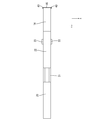
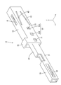
- FIG. Sectional view showing the electric wire with terminal The perspective view which shows a connection cylinder part, an extending part, and an electric wire connection part Side view showing connecting cylinder, extension, and wire connection
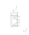
- Sectional drawing which shows the state by which the slide part was hold
- the side view which shows the state by which the electric wire was inserted in the state in which the slide part was hold
- Sectional drawing which shows the state by which the electric wire was inserted in the state by which the slide part was hold
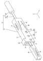
- the electric wire with terminal 10 includes an electric wire 11 and a female terminal 12 (an example of a terminal) connected to the electric wire 11.
- symbol may be attached
- the electric wire 11 includes a core wire 13 and an insulating coating 35 made of an insulating synthetic resin that covers the outer periphery of the core wire 13.
- a small-diameter core wire 13A having a relatively small diameter and a large-diameter core wire 13B having a relatively large diameter can be selected.
- a metal which comprises the core wire 13 it can select suitably from arbitrary metals as needed, such as copper, a copper alloy, aluminum, an aluminum alloy.
- the core wire 13 according to the present embodiment is made of copper or a copper alloy.
- the core wire 13 may be a stranded wire formed by twisting a plurality of metal strands, or may be a single core wire made of one rod-shaped metal material.
- the core wire 13 which concerns on this embodiment consists of a single core wire.
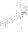
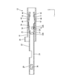
- the female terminal 12 includes an electric wire connecting portion 19 having a first holding portion 14 (an example of a holding portion) and a second holding portion 15 (an example of a holding portion) that hold the core wire 13 of the electric wire 11. And a slide part 18 slidably attached to the electric wire connection part 19.
- the female terminal 12 is made of a conductive metal material. As a metal which comprises the female terminal 12, it can select suitably from arbitrary metals as needed, such as copper, copper alloy, aluminum, aluminum alloy.
- the terminal according to the present embodiment is made of copper or a copper alloy.
- the female terminal 12 can be formed by a known method such as cutting, casting, or pressing.
- the female terminal 12 has a connecting cylinder portion 20 into which a male terminal (not shown) is inserted.
- the connecting tube portion 20 has a rectangular tube shape extending in the front-rear direction.
- the connecting cylinder part 20 is open forward and backward.
- An elastic contact piece 36 that protrudes inward of the connection cylinder part 20 is provided on the left side wall of the connection cylinder part 20.
- the elastic contact piece 36 extends forward from a position near the rear end portion of the connecting cylinder portion.
- the elastic contact piece 36 elastically contacts the male terminal, whereby the male terminal and the female terminal 12 are electrically connected.
- the rear end portion of the connecting tube portion 20 is connected to an extending portion 21 extending rearward.
- the wire connecting portion 19 is connected to the rear end portion of the extending portion 21.
- the electric wire connecting portion 19 includes a base portion 22 and a first holding portion 14 and a second holding portion 15 that extend rearward (an example of the extending direction) from the rear end portion of the base portion 22.
- the extended portion 21 is formed to open upward. Thereby, the core wire 13 arranged inside the extending portion 21 can be viewed from above.
- the base 22 has a rectangular tube shape extending in the front-rear direction.
- the base 22 opens forward and backward.
- the first clamping part 14 extends obliquely upward and rearward (an example of the extending direction).
- the first extending end portion 46 of the first sandwiching portion 14 is located above the rear end portion of the base portion 22.
- the first extending end portion 46 of the first sandwiching portion 14 is disposed at a position that is wider than the rear end portion of the base portion 22 in the front-rear direction.
- the 1st clamping part 14 has comprised the plate shape elongated in the front-back direction.
- the 1st clamping part 14 is formed so that bending deformation is possible about the plate
- Two first bosses 40 projecting outward in the left-right direction are provided on the left and right ends of the first extending end 46 of the first clamping part 14.
- the projecting dimension of the first boss 40 in the left-right direction from the side edge of the first clamping part is set to be substantially the same as the thickness dimension of the left and right side walls of the slide part 18. “Substantially the same” includes the case where the protruding dimension of the first boss 40 and the thickness dimension of the left and right side walls of the slide portion 18 are the same, and the case where the first boss 40 is recognized to be substantially the same even if it is not the same.
- the lower surface of the first clamping unit 14 is a first contact surface 24 that contacts the core wire 13.
- a first protrusion 25 that protrudes downward from the first contact surface 24 is formed at a position near the front end of the first sandwiching portion 14.
- a plurality of first serrations 26 that extend in the left-right direction and are arranged at intervals in the front-rear direction in the first contact surface 24 of the first holding portion 14 at a position behind the first protrusion 25 are V-shaped grooves. (See FIG. 6).
- the second sandwiching portion 15 extends obliquely downward and rearward (an example of the extending direction) from the rear end portion of the lower wall of the base portion 22.
- the second extending end portion 47 of the second sandwiching portion 15 is positioned below the rear end portion of the base portion 22.
- the second extending end portion 47 of the second sandwiching portion 15 is disposed at a position that is wider than the rear end portion of the base portion 22 in the front-rear direction.
- the 2nd clamping part 15 has comprised the plate shape elongated in the front-back direction.
- the 2nd clamping part 15 is formed so that bending deformation is possible about a plate
- Two left and right end portions of the second extending end portion 47 of the second holding portion 15 are provided with two second bosses 41 protruding outward in the left-right direction.
- the projecting dimension of the second boss 41 in the left-right direction from the side edge of the second clamping part is set to be substantially the same as the thickness dimension of the left and right side walls of the slide part 18.
- substantially the same includes the case where the protruding dimension of the second boss 41 and the thickness dimension of the left and right side walls of the slide portion 18 are the same, and the case where they are recognized to be substantially the same even if they are not the same.
- the upper surface of the second clamping unit 15 is a second contact surface 27 that contacts the core wire 13.
- a second protrusion 28 protruding upward from the second contact surface 27 is provided on the second contact surface 27 of the second sandwiching portion 15 at a position rearward of the rear end portion of the first protrusion of the first sandwiching portion 14. Is formed.
- the slide part 18 has a rectangular tube shape elongated in the front-rear direction, and is open in the front-rear direction.
- the opening on the front side of the slide portion 18 is formed to be the same as or slightly larger than the outer shape of the wire connection portion 19, and the wire connection portion 19 can be inserted.
- the slide portion 18 can be formed of any material such as metal, synthetic resin, ceramic, or the like as necessary.
- a metal which comprises the slide part 18 arbitrary metals can be suitably selected as needed, such as copper, copper alloy, aluminum, aluminum alloy, and stainless steel.
- the slide portion 18 is formed of a metal, it can be formed by any method as necessary, such as cutting, casting, or pressing.
- a jig contact portion 30 protruding upward is provided at the front end portion of the upper wall of the slide portion 18.
- the slide portion 18 slides forward.
- the slide portion 18 is elastically locked with the locking projections 23 at positions on the left side wall and the front end portion of the right side wall of the slide portion 18 so that the slide portion 18 is connected to the electric wire.
- a temporary locking portion 31 that is held at a temporary locking position with respect to the portion 19 is provided.
- the temporary locking portion 31 is formed as a through-hole penetrating the left side wall and the right side wall of the slide portion 18.
- the size of the hole edge of the temporary locking portion 31 is the same as or slightly larger than that of the locking projection 23, and the locking projection 23 can be fitted into the temporary locking portion 31.
- the left side wall and the right side wall of the slide part 18 are respectively elastically locked to the locking projections 23 behind the temporary locking part 31, and the slide part 18 is connected to the wire connection part 19.
- a plurality (two in this embodiment) of main locking portions 32 held at the main locking position are provided side by side in the front-rear direction.
- the main locking portion 32 is formed as a through-hole penetrating the left side wall and the right side wall of the slide portion 18.
- the size of the hole edge of the main locking part 32 is the same as or slightly larger than that of the locking protrusion 23, and the locking protrusion 23 can be fitted into the main locking part 32.
- the main locking portion 32 provided on each side wall of the slide portion 18 includes a large deformation locking portion 32A located on the rear side, and a small deformation locking portion 32B positioned in front of the large deformation locking portion 32A. ,including.
- the locking projection 23 is locked to the large deformation locking portion 32A
- the slide portion 18 is held at the large deformation locking position with respect to the electric wire connection portion 19, and the locking projection 23 is small.
- the slide portion 18 is held at the small deformation locking position with respect to the electric wire connecting portion 19 by being locked to the deformation locking portion 32B.
- a first projection 16 projecting downward is formed on the lower surface of the upper wall of the slide part 18 at a position rearward of the center position in the front-rear direction and extending in the front-rear direction.
- the rear end portion of the first projecting portion 16 extends to a position slightly ahead of the rear end portion of the slide portion 18 material.
- the projecting dimension of the first projecting portion 16 from the upper wall of the slide portion 18 is set so as to increase toward the rear.
- the lower surface of the 1st protrusion part 16 is made into the 1st inclined surface 44 which inclines and descends toward back (an example of a pressurization part and an inclined surface).
- the first inclined surface 44 according to the present embodiment is formed as a flat surface.
- the first inclined surface 44 faces the lower surface of the first clamping unit 14.
- the first inclined surface 44 may be a curved surface.
- a second projecting part 17 projecting upward is formed on the upper surface of the lower wall of the slide part 18 at a position rearward of the central position in the front-rear direction and extending in the front-rear direction.
- the rear end portion of the second projecting portion 17 extends to a position slightly ahead of the rear end portion of the slide portion 18 material.
- the projecting dimension of the second projecting portion 17 from the lower wall of the slide portion 18 is set to increase toward the rear.
- the upper surface of the 2nd protrusion part 17 is made into the 2nd inclined surface 45 which ascends as it goes back (an example of a pressurization part and an inclined surface).
- the second inclined surface 45 according to the present embodiment is formed as a flat surface.
- the second inclined surface 45 is opposed to the upper surface of the second clamping part.
- the second inclined surface 45 may be a curved surface.
- the shapes of the first protrusion 16 and the second protrusion 17 are formed symmetrically in the vertical direction. Thereby, the 1st inclined surface 44 and the 2nd inclined surface 45 are also formed symmetrically about the up-down direction. In addition, the 1st protrusion part 16 and the 2nd protrusion part 17 may be asymmetrical about an up-down direction.
- first guide grooves 42 are formed on the left and right side walls of the slide portion 18 at positions above the center in the vertical direction. Has been.
- the front end portion of the first guide groove 42 extends further forward than the front end portion of the first protrusion.
- the rear end portion of the first guide groove 42 extends rearward from the rear end portion of the first projecting portion.
- the first guide groove 42 according to the present embodiment is formed through the side wall of the slide portion 18. The first guide groove 42 may not penetrate the side wall of the slide portion 18.
- the first guide groove 42 is formed to be inclined downward in a straight line from the front to the rear.
- the 1st guide groove 42 may be formed in the curved downward inclination.
- 2nd guide groove 43 (an example of a pressurization part and a guide groove) is formed in the position below the center about the up-down direction at the both right and left side walls of the slide part 18, respectively.
- the front end portion of the second guide groove 43 extends further forward than the front end portion of the second protrusion.
- the rear end portion of the second guide groove 43 extends rearward from the rear end portion of the second protrusion.
- the second guide groove 43 according to the present embodiment is formed through the side wall of the slide portion 18. Note that the second guide groove 43 may not penetrate the side wall of the slide portion 18.
- the second guide groove 43 is formed to be inclined upward in a straight line from the front to the rear.
- the 2nd guide groove 43 may be formed in the curving downward inclination.
- first guide groove 42 and the second guide groove 43 are formed symmetrically in the vertical direction. Note that the first guide groove 42 and the second guide groove 43 may be asymmetric in the vertical direction.
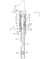
- FIGS. 10 to 12 show a state in which the slide portion 18 is temporarily locked to the wire connecting portion 19.
- the locking protrusion 23 of the electric wire connection portion 19 is fitted inside the temporary locking portion 31 of the slide portion 18.
- the front half portion of the slide portion 18 is approximately two thirds long from the rear end portion in the front-rear direction of the electric wire connection portion 19. It is externally fitted up to the size.
- the rear end portion of the first clamping portion 14 is located in front of the front end portion of the first projecting portion 16.
- the rear end portion of the second sandwiching portion 15 is located in front of the front end portion of the second projecting portion 17.
- the first sandwiching portion 14 and the first projecting portion 16 are not in contact with each other, and the second sandwiching portion 15 and the second projecting portion 17 are not in contact with each other.
- the first boss 40 of the first clamping portion 14 is fitted into the first guide groove 42 of the slide portion 18, and the front end of the first guide groove 42. It is located slightly behind the part.
- the second boss 41 of the second sandwiching portion 15 is fitted into the second guide groove 43 of the slide portion 18, and slightly from the front end portion of the second guide groove 43. Located behind.
- FIGS. 1 to 2 and FIG. 15 show a state in which the slide portion 18 is permanently locked to the large deformation locking portion 32A of the wire connecting portion 19.
- FIG. The locking projection 23 of the electric wire connection portion 19 is fitted inside the large deformation locking portion 32 ⁇ / b> A of the slide portion 18.
- the slide portion 18 In a state where the slide portion 18 is held at the large deformation locking position with respect to the electric wire connection portion 19, the slide portion 18 completely covers the electric wire connection portion 19 in the front-rear direction.
- the front end portion of the slide portion 18 is located in front of the front end portion of the electric wire connection portion 19, and the rear end portion of the slide portion 18 is located rearward of the rear end portion of the electric wire connection portion 19.
- the 1st protrusion part 16 is contact
- the second projecting portion 17 is in contact with the lower surface of the second sandwiching portion 15 (the surface opposite to the second contact surface 27) from below. Thereby, the 2nd clamping part 15 bends upwards and is contact
- the first boss 40 is located at the rear end portion of the first guide groove 42 in the large deformation locking position. Therefore, when the 1st extension end part 46 of the 1st clamping part 14 deform
- the second boss 41 is located at the rear end of the second guide groove 43.
- the second extending end portion 47 of the second holding portion 15 is deformed upward, so that the second holding portion 15 contacts the small-diameter core wire 13A from above.
- the first sandwiching portion 14 abuts on the first projecting portion 16 from above and the second sandwiching portion 15 abuts on the second projecting portion 17 from below so that the first sandwiching portion 14 and the second sandwiching portion 15 are in contact with each other.
- the small-diameter core wire 13 ⁇ / b> A arranged therebetween is sandwiched between the first sandwiching portion 14 and the second sandwiching portion 15. Thereby, the electric wire 11 and the female terminal 12 are electrically connected.
- the small-diameter core wire 13 ⁇ / b> A is sandwiched between the first protrusion 25 of the first holding part 14 and the second protrusion 28 of the second holding part 15 provided so as to be shifted in the front-rear direction. It is bent in a crank shape. Thereby, the small-diameter core wire 13 ⁇ / b> A is firmly held between the first sandwiching portion 14 and the second sandwiching portion 15.
- the small-diameter core wire 13 ⁇ / b> A is fitted inside the first serration 26 formed on the first contact surface 24. Thereby, the oxide film formed on the surface of the small-diameter core wire 13A is peeled off to expose the metal surface. When the exposed metal surface and the first contact surface 24 come into contact with each other, the electrical resistance between the first sandwiching portion 14 and the small-diameter core wire 13A can be reduced.
- the small diameter core wire 13A is inserted into the second serration 29 formed on the second contact surface 27.
- the oxide film formed on the surface of the small-diameter core wire 13A is peeled off to expose the metal surface.
- the electrical resistance between the second sandwiching portion 15 and the small-diameter core wire 13A can be reduced.
- Full lock state (small deformation lock state) 16 to 17 show a state in which the slide portion 18 is permanently locked to the small deformation locking portion 32B of the electric wire connection portion 19.
- FIG. The locking projection 23 of the electric wire connection portion 19 is fitted inside the small deformation locking portion 32B of the slide portion 18.
- the front end portion of the wire connection portion 19 protrudes forward from the front end portion of the slide portion 18, and the wire connection portion 19.
- the rear end portion is located in front of the rear end portion of the slide portion 18.
- a large-diameter core wire 13B is used in which the diameter dimension of the core wire 13 is larger than that of the small-diameter core wire 13A.
- the 1st protrusion part 16 is contact
- the second projecting portion 17 is in contact with the lower surface of the second sandwiching portion 15 (the surface opposite to the second contact surface 27) from below. Thereby, the 2nd clamping part 15 bends upwards and is contact
- the first boss 40 is located in the vicinity of the center position in the front-rear direction in the first guide groove 42 at the small deformation locking position.
- the second boss 41 In the small deformation locking position, the second boss 41 is located in the vicinity of the center position in the front-rear direction in the second guide groove 43. Thereby, when the 2nd extension end part 47 of the 2nd clamping part 15 deform
- the first sandwiching portion 14 abuts on the first projecting portion 16 from above and the second sandwiching portion 15 abuts on the second projecting portion 17 from below so that the first sandwiching portion 14 and the second sandwiching portion 15 are in contact with each other.
- the large-diameter core wire 13 ⁇ / b> B arranged therebetween is sandwiched between the first sandwiching portion 14 and the second sandwiching portion 15. Thereby, the electric wire 11 and the female terminal 12 are electrically connected.
- the downward deformation amount of the first clamping portion 14 and the upward deformation amount of the second clamping portion 15 are the downward deformation of the first clamping portion 14 in the large deformation locking position. It is smaller than the amount and the upward deformation amount of the second sandwiching portion 15. Thereby, an appropriate pressing force can be applied to the large-diameter core wire 13B.
- the large-diameter core wire 13 ⁇ / b> B is sandwiched between the first protrusion 25 of the first holding part 14 and the second protrusion 28 of the second holding part 15 provided so as to be shifted in the front-rear direction. Therefore, it is bent into a crank shape. Thereby, the large-diameter core wire 13 ⁇ / b> B is firmly held between the first sandwiching portion 14 and the second sandwiching portion 15.
- the large-diameter core wire 13B fits inside the first serration 26 formed on the first contact surface 24. Thereby, the oxide film formed on the surface of the large-diameter core wire 13B is peeled off and the metal surface is exposed. When the exposed metal surface and the first contact surface 24 come into contact with each other, the electrical resistance between the first sandwiching portion 14 and the large-diameter core wire 13B can be reduced.
- the large-diameter core wire 13B is inserted into the second serration 29 formed on the second contact surface 27. Thereby, the oxide film formed on the surface of the large-diameter core wire 13B is peeled off and the metal surface is exposed. When the exposed metal surface and the second contact surface 27 come into contact with each other, the electrical resistance between the second sandwiching portion 15 and the large-diameter core wire 13B can be reduced.
- connection process of female terminal 12 and electric wire 11 An example of a connection process of female terminal 12 and electric wire 11 Then, an example of a connection process of female terminal 12 and electric wire 11 concerning this embodiment is explained. In addition, about the connection process of the female terminal 12 and the electric wire 11, it is not limited to the following description.
- the slide part 18 is externally fitted to the electric wire connection part 19 of the female terminal 12 from behind.
- the rear end portion of the electric wire connecting portion 19 of the female terminal 12 is inserted into the opening on the front side of the slide portion 18, and the slide portion 18 is moved forward.
- the first boss 40 of the first clamping part 14 and the second boss 41 of the second clamping part 15 abut against the opening edge on the front side of the slide part 18 from the front, the left and right side walls of the slide part 18 are laterally moved. Elastically deform outward.
- the slide portion 18 is further moved forward, the locking projection 23 of the wire connection portion 19 comes into contact with the opening edge on the front side of the slide portion 18 from the front. Then, the left and right side walls of the slide portion 18 are elastically deformed outward in the left-right direction.
- the first boss 40 is fitted in the first guide groove 42
- the second boss 41 is fitted in the second guide groove 43, and is locked in the temporary locking portion 31.
- the protrusions 23 are inserted, and the left and right side walls of the slide portion 18 are restored and deformed.
- the locking projection 23 abuts against the hole edge of the temporary locking portion 31 from the front or the rear, so that the slide portion 18 is held at the temporary locking position with respect to the electric wire connection portion 19.
- the first extending end portion 46 of the first sandwiching portion 14 and the second extending end portion 47 of the second sandwiching portion 15 are held at a position expanded with respect to the rear end portion of the base portion 22 ( (See FIGS. 10 to 12).
- the insulation coating 35 is peeled off at the end of the electric wire 11 to expose the small-diameter core wire 13A.
- the exposed small-diameter core wire 13A is inserted from the opening on the rear side of the slide portion 18. Further, the small-diameter core wire 13A is inserted forward so that the front end portion of the small-diameter core wire 13A is positioned inside the extending portion 21.
- the front end portion of the small-diameter core wire 13 ⁇ / b> A is located inside the extended portion 21.
- the jig 34 is brought into contact with the jig abutting portion 30 from the rear and pressed from the rear, thereby moving the slide portion 18 forward. Then, the left and right side walls of the slide portion 18 ride on the locking projections 23 of the wire connection portion 19. As a result, the left and right side walls of the wire connecting portion 19 are elastically deformed inward in the left-right direction.
- the first projecting portion 16 comes into contact with the upper surface of the first holding portion 14 from above and the second projecting portion 17 comes into contact with the lower surface of the second holding portion 15 from below.
- the slide portion 18 by moving the slide portion 18 forward, the first inclined surface 44 of the first projecting portion 16 presses the first sandwiching portion 14 from above to below, and the second inclined surface 45 of the second projecting portion 17 is moved.
- the second clamping unit 15 is pressed from below to above. Accordingly, the first sandwiching portion 14 is deformed downward and the second sandwiching portion 15 is deformed upward, whereby the small-diameter core wire 13A is sandwiched between the first sandwiching portion 14 and the second sandwiching portion 15.
- the female terminal 12 is a female terminal 12 connected to the electric wire 11, and includes a base portion 22, a first holding portion 14 that extends from the base portion 22 in the extending direction, and holds the electric wire 11.
- the electric wire connecting part 19 having the second holding part 15 and the slide part 18 slidable along the extending direction (front-rear direction) in the electric wire connecting part 19 include the first holding part 14 and the slide part 18.
- the first inclined surface 44 and the second inclined surface 45 are provided.
- the wire connecting portion 19 has a first boss 40 and a second boss 41, and the slide portion 18 has a first guide groove 42 with which the first boss 40 is engaged and a second boss 41 with which the second boss 41 is engaged.
- Two guide grooves 43 are provided.
- the amount of deformation of the first clamping unit 14 and the second clamping unit 15 in the direction toward the electric wire 11 can be changed by the amount of movement of the slide unit 18. Thereby, it can respond to the electric wire 11 of a different standard with the female terminal 12 of one standard. As a result, an increase in the number of parts can be suppressed, and the manufacturing cost of the female terminal 12 can be reduced.
- sliding along the extending direction includes the case where the slide portion slides parallel to the extending direction, and even if the sliding part is not parallel to the extending direction, it extends substantially on the basis of the extending direction. This includes the case where the slide part slides according to the direction.
- the slide portion 18 is provided with the first inclined surface 44 facing the first sandwiching portion 14 and the second inclined surface 45 facing the second sandwiching portion 15.
- the first clamping part 14 is pressurized by the first inclined surface 44 and the second clamping part 15 is pressurized by the second inclined surface 45, so that the first clamping part 14 and the second clamping part 15 are reliably pressed. Can exert pressure.
- the first clamping unit 14 has the first boss 40
- the second clamping unit 15 has the second boss 41.
- a first guide groove 42 with which the first boss 40 is engaged is formed in the slide portion
- a second guide groove 43 with which the second boss 41 is engaged is formed.
- the 1st guide groove 42 and the 2nd guide groove 43 are inclined and extended along the extending direction (front-back direction).
- the slide portion 18 has a relative position between the wire connecting portion 19 and the slide portion 18, and the first holding portion 14 and the second holding portion 15 do not pressurize the core wire 13.
- the temporary holding portion 31 held at the locking position, and the relative positions of the wire connecting portion 19 and the slide portion 18 are set to the main locking position where the first holding portion 14 and the second holding portion 15 pressurize the core wire 13.
- the main locking portion 32 is provided, and the main locking portion 32 includes a large deformation locking portion 32A in which the deformation amount of the first holding portion 14 and the second holding portion 15 is relatively large, A small deformation locking portion 32B in which the deformation amount of the first sandwiching portion 14 and the second sandwiching portion 15 is relatively small.
- the second extending end portion 47 is arranged at a position that is wider than the base portion 22 as it goes rearward from the base portion 22.
- the electric wire 11 is electric wire.
- the operation of inserting into the connecting portion 19 can be easily performed. Thereby, the efficiency of the connection work of the female terminal 12 and the electric wire 11 can be improved.
- the terminal is the female terminal 12 in the above embodiment, the terminal is not limited to this, and may be a male terminal, a round terminal, or a splice terminal that connects the plurality of electric wires 11 to each other.
- the electric wire 11 is a covered electric wire, but may be a bare electric wire. Moreover, the electric wire 11 may be a stranded wire in which a plurality of fine metal wires are twisted together.
- the female terminal 12 has the first clamping portion 14 and the second clamping portion 15.
- the present invention is not limited to this, and the number of clamping portions may be one, or three or more. But you can.
- the base portion 22 has a rectangular tube shape, but is not limited thereto, and may be a polygonal tube shape such as a cylindrical shape, a triangular tube shape, or a hexagonal tube shape.
- the slide part 18 material may also be a cylindrical shape, and may be a polygonal cylindrical shape such as a triangular cylindrical shape.
- a pressurizing part is good also as only an inclined surface. Moreover, it is good also as only a guide groove and a boss
- the main locking portion 32 includes the large deformation locking portion 32A and the small deformation locking portion 32B.
- the present locking portion 32 is not limited to this, and depending on the deformation amount of the clamping portion, It is good also as a structure by which three or more book latching
- the present invention is not limited to this, and the appropriate pressing force on the core wire 13 can be obtained by different materials. Even when different, the technique described in the present specification can be suitably used.
Landscapes
- Connections Effected By Soldering, Adhesion, Or Permanent Deformation (AREA)
- Connector Housings Or Holding Contact Members (AREA)
Priority Applications (2)
| Application Number | Priority Date | Filing Date | Title |
|---|---|---|---|
| US16/967,550 US20210234286A1 (en) | 2018-02-15 | 2019-02-04 | Terminal |
| CN201980011874.8A CN111684663B (zh) | 2018-02-15 | 2019-02-04 | 端子 |
Applications Claiming Priority (2)
| Application Number | Priority Date | Filing Date | Title |
|---|---|---|---|
| JP2018-025419 | 2018-02-15 | ||
| JP2018025419A JP6954170B2 (ja) | 2018-02-15 | 2018-02-15 | 端子 |
Publications (1)
| Publication Number | Publication Date |
|---|---|
| WO2019159730A1 true WO2019159730A1 (ja) | 2019-08-22 |
Family
ID=67619049
Family Applications (1)
| Application Number | Title | Priority Date | Filing Date |
|---|---|---|---|
| PCT/JP2019/003793 Ceased WO2019159730A1 (ja) | 2018-02-15 | 2019-02-04 | 端子 |
Country Status (4)
| Country | Link |
|---|---|
| US (1) | US20210234286A1 (https=) |
| JP (1) | JP6954170B2 (https=) |
| CN (1) | CN111684663B (https=) |
| WO (1) | WO2019159730A1 (https=) |
Cited By (4)
| Publication number | Priority date | Publication date | Assignee | Title |
|---|---|---|---|---|
| WO2020196478A1 (ja) * | 2019-03-28 | 2020-10-01 | 株式会社オートネットワーク技術研究所 | ジョイントコネクタ |
| WO2020196480A1 (ja) * | 2019-03-28 | 2020-10-01 | 株式会社オートネットワーク技術研究所 | ジョイントコネクタ |
| JP2021034307A (ja) * | 2019-08-28 | 2021-03-01 | 株式会社オートネットワーク技術研究所 | 端子、および端子付き電線 |
| WO2021182373A1 (ja) * | 2020-03-12 | 2021-09-16 | 株式会社オートネットワーク技術研究所 | 端子、および端子付き電線 |
Families Citing this family (6)
| Publication number | Priority date | Publication date | Assignee | Title |
|---|---|---|---|---|
| JP7133513B2 (ja) * | 2019-06-12 | 2022-09-08 | 株式会社オートネットワーク技術研究所 | 端子、および端子付き電線 |
| WO2020250800A1 (ja) | 2019-06-12 | 2020-12-17 | 株式会社オートネットワーク技術研究所 | 端子、および端子付き電線 |
| JP7353922B2 (ja) * | 2019-11-07 | 2023-10-02 | 古河電気工業株式会社 | 接続構造体、ハウジング付接続構造体、及び、端子 |
| JP7353921B2 (ja) * | 2019-11-07 | 2023-10-02 | 古河電気工業株式会社 | 接続構造体、ハウジング付接続構造体、及び、端子 |
| JP2021190286A (ja) * | 2020-05-29 | 2021-12-13 | 株式会社オートネットワーク技術研究所 | 端子、および端子付き電線 |
| JP7478057B2 (ja) | 2020-07-30 | 2024-05-02 | タイコエレクトロニクスジャパン合同会社 | 電気端子 |
Citations (4)
| Publication number | Priority date | Publication date | Assignee | Title |
|---|---|---|---|---|
| JPS4998795U (https=) * | 1972-12-16 | 1974-08-26 | ||
| US20020119710A1 (en) * | 2001-02-27 | 2002-08-29 | Fci Usa, Inc. | Electrical connector having frame and slidable members |
| JP2011014466A (ja) * | 2009-07-03 | 2011-01-20 | Tyco Electronics Japan Kk | コネクタ |
| JP2015056209A (ja) * | 2013-09-10 | 2015-03-23 | ヒロセ電機株式会社 | 電気コネクタ用端子及び電気コネクタ |
Family Cites Families (11)
| Publication number | Priority date | Publication date | Assignee | Title |
|---|---|---|---|---|
| JPS325148Y1 (https=) * | 1955-05-25 | 1957-06-12 | ||
| US6688905B2 (en) * | 2001-04-09 | 2004-02-10 | Roger Williams | Field attachable electrical connector and self-tightening method of strain relief |
| DE20119530U1 (de) * | 2001-12-01 | 2002-04-18 | HARTING Electric GmbH & Co. KG, 32339 Espelkamp | Elektrisches Kontaktelement |
| JP2006049211A (ja) * | 2004-08-06 | 2006-02-16 | Three M Innovative Properties Co | 同軸ケーブル接地構造並びにコネクタ及びその結線方法 |
| US7086897B2 (en) * | 2004-11-18 | 2006-08-08 | John Mezzalingua Associates, Inc. | Compression connector and method of use |
| US20090215306A1 (en) * | 2006-05-26 | 2009-08-27 | Centerpin Technology, Inc. | Electrical connector with compression gores |
| US7934954B1 (en) * | 2010-04-02 | 2011-05-03 | John Mezzalingua Associates, Inc. | Coaxial cable compression connectors |
| JP5274693B1 (ja) * | 2012-06-15 | 2013-08-28 | 昌範 木本 | 電力ケーブル用接続器 |
| JP2015156285A (ja) * | 2014-02-20 | 2015-08-27 | 住友電装株式会社 | 接続端子及びワイヤーハーネス |
| JP6086940B2 (ja) * | 2015-06-03 | 2017-03-01 | 株式会社木村電気工業 | 電線接続装置 |
| CN106025584A (zh) * | 2016-05-02 | 2016-10-12 | 胡小青 | 用于电力线路的夹线金具 |
-
2018
- 2018-02-15 JP JP2018025419A patent/JP6954170B2/ja active Active
-
2019
- 2019-02-04 CN CN201980011874.8A patent/CN111684663B/zh active Active
- 2019-02-04 WO PCT/JP2019/003793 patent/WO2019159730A1/ja not_active Ceased
- 2019-02-04 US US16/967,550 patent/US20210234286A1/en not_active Abandoned
Patent Citations (4)
| Publication number | Priority date | Publication date | Assignee | Title |
|---|---|---|---|---|
| JPS4998795U (https=) * | 1972-12-16 | 1974-08-26 | ||
| US20020119710A1 (en) * | 2001-02-27 | 2002-08-29 | Fci Usa, Inc. | Electrical connector having frame and slidable members |
| JP2011014466A (ja) * | 2009-07-03 | 2011-01-20 | Tyco Electronics Japan Kk | コネクタ |
| JP2015056209A (ja) * | 2013-09-10 | 2015-03-23 | ヒロセ電機株式会社 | 電気コネクタ用端子及び電気コネクタ |
Cited By (16)
| Publication number | Priority date | Publication date | Assignee | Title |
|---|---|---|---|---|
| US11942737B2 (en) | 2019-03-28 | 2024-03-26 | Autonetworks Technologies, Ltd. | Joint connector |
| WO2020196480A1 (ja) * | 2019-03-28 | 2020-10-01 | 株式会社オートネットワーク技術研究所 | ジョイントコネクタ |
| WO2020196478A1 (ja) * | 2019-03-28 | 2020-10-01 | 株式会社オートネットワーク技術研究所 | ジョイントコネクタ |
| US12062874B2 (en) | 2019-03-28 | 2024-08-13 | Autonetworks Technologies, Ltd. | Joint connector |
| JP2021034307A (ja) * | 2019-08-28 | 2021-03-01 | 株式会社オートネットワーク技術研究所 | 端子、および端子付き電線 |
| WO2021039359A1 (ja) * | 2019-08-28 | 2021-03-04 | 株式会社オートネットワーク技術研究所 | 端子、および端子付き電線 |
| CN114270629A (zh) * | 2019-08-28 | 2022-04-01 | 株式会社自动网络技术研究所 | 端子及带端子电线 |
| US20220294131A1 (en) * | 2019-08-28 | 2022-09-15 | Autonetworks Technologies, Ltd. | Terminal and wire with terminal |
| CN114270629B (zh) * | 2019-08-28 | 2024-04-02 | 株式会社自动网络技术研究所 | 端子及带端子电线 |
| JP7216895B2 (ja) | 2019-08-28 | 2023-02-02 | 株式会社オートネットワーク技術研究所 | 端子、および端子付き電線 |
| WO2021182373A1 (ja) * | 2020-03-12 | 2021-09-16 | 株式会社オートネットワーク技術研究所 | 端子、および端子付き電線 |
| JP7310661B2 (ja) | 2020-03-12 | 2023-07-19 | 株式会社オートネットワーク技術研究所 | 端子、および端子付き電線 |
| CN115244788A (zh) * | 2020-03-12 | 2022-10-25 | 株式会社自动网络技术研究所 | 端子以及带端子的电线 |
| JP2021144870A (ja) * | 2020-03-12 | 2021-09-24 | 株式会社オートネットワーク技術研究所 | 端子、および端子付き電線 |
| US12230933B2 (en) | 2020-03-12 | 2025-02-18 | Autonetworks Technologies, Ltd. | Terminal and wire with terminal |
| CN115244788B (zh) * | 2020-03-12 | 2025-08-12 | 株式会社自动网络技术研究所 | 端子以及带端子的电线 |
Also Published As
| Publication number | Publication date |
|---|---|
| US20210234286A1 (en) | 2021-07-29 |
| CN111684663B (zh) | 2022-08-23 |
| JP2019145214A (ja) | 2019-08-29 |
| JP6954170B2 (ja) | 2021-10-27 |
| CN111684663A (zh) | 2020-09-18 |
Similar Documents
| Publication | Publication Date | Title |
|---|---|---|
| WO2019159730A1 (ja) | 端子 | |
| WO2019159746A1 (ja) | 端子、及び端子付き電線 | |
| JP2019145210A (ja) | 端子付き電線 | |
| CN107453182A (zh) | 具有端子的电线的制造方法 | |
| CN113574738A (zh) | 端子及带端子电线 | |
| CN101227030B (zh) | 金属端子 | |
| JP6156185B2 (ja) | 端子付き電線 | |
| CN113678320B (zh) | 端子及带端子电线 | |
| CN113875091A (zh) | 端子及带端子的电线 | |
| WO2020226056A1 (ja) | 端子、および端子付き電線 | |
| CN115244788B (zh) | 端子以及带端子的电线 | |
| WO2021039359A1 (ja) | 端子、および端子付き電線 | |
| CN115668646A (zh) | 端子及带端子的电线 | |
| CN114128055B (zh) | 端子及带端子的电线 | |
| CN113646970B (zh) | 端子及带端子电线 | |
| JP7113796B2 (ja) | 端子、および端子付き電線 | |
| JP2006049117A (ja) | 端子付電線及びその製造方法 | |
| WO2017068965A1 (ja) | 端子付き電線の製造方法、圧着冶具、および端子付き電線 | |
| JP2010062099A (ja) | 端子金具及び端子金具の電線への接続方法 |
Legal Events
| Date | Code | Title | Description |
|---|---|---|---|
| 121 | Ep: the epo has been informed by wipo that ep was designated in this application |
Ref document number: 19753895 Country of ref document: EP Kind code of ref document: A1 |
|
| NENP | Non-entry into the national phase |
Ref country code: DE |
|
| 122 | Ep: pct application non-entry in european phase |
Ref document number: 19753895 Country of ref document: EP Kind code of ref document: A1 |