WO2019150899A1 - 電気部品製造装置および電気部品の製造方法 - Google Patents
電気部品製造装置および電気部品の製造方法 Download PDFInfo
- Publication number
- WO2019150899A1 WO2019150899A1 PCT/JP2019/000431 JP2019000431W WO2019150899A1 WO 2019150899 A1 WO2019150899 A1 WO 2019150899A1 JP 2019000431 W JP2019000431 W JP 2019000431W WO 2019150899 A1 WO2019150899 A1 WO 2019150899A1
- Authority
- WO
- WIPO (PCT)
- Prior art keywords
- heating
- preheating
- melting
- workpiece
- unit
- Prior art date
- Legal status (The legal status is an assumption and is not a legal conclusion. Google has not performed a legal analysis and makes no representation as to the accuracy of the status listed.)
- Ceased
Links
Images





Classifications
-
- B—PERFORMING OPERATIONS; TRANSPORTING
- B23—MACHINE TOOLS; METAL-WORKING NOT OTHERWISE PROVIDED FOR
- B23K—SOLDERING OR UNSOLDERING; WELDING; CLADDING OR PLATING BY SOLDERING OR WELDING; CUTTING BY APPLYING HEAT LOCALLY, e.g. FLAME CUTTING; WORKING BY LASER BEAM
- B23K31/00—Processes relevant to this subclass, specially adapted for particular articles or purposes, but not covered by any single one of main groups B23K1/00 - B23K28/00
- B23K31/02—Processes relevant to this subclass, specially adapted for particular articles or purposes, but not covered by any single one of main groups B23K1/00 - B23K28/00 relating to soldering or welding
-
- B—PERFORMING OPERATIONS; TRANSPORTING
- B23—MACHINE TOOLS; METAL-WORKING NOT OTHERWISE PROVIDED FOR
- B23K—SOLDERING OR UNSOLDERING; WELDING; CLADDING OR PLATING BY SOLDERING OR WELDING; CUTTING BY APPLYING HEAT LOCALLY, e.g. FLAME CUTTING; WORKING BY LASER BEAM
- B23K1/00—Soldering, e.g. brazing, or unsoldering
- B23K1/0008—Soldering, e.g. brazing, or unsoldering specially adapted for particular articles or work
- B23K1/0016—Soldering of electronic components
-
- B—PERFORMING OPERATIONS; TRANSPORTING
- B23—MACHINE TOOLS; METAL-WORKING NOT OTHERWISE PROVIDED FOR
- B23K—SOLDERING OR UNSOLDERING; WELDING; CLADDING OR PLATING BY SOLDERING OR WELDING; CUTTING BY APPLYING HEAT LOCALLY, e.g. FLAME CUTTING; WORKING BY LASER BEAM
- B23K1/00—Soldering, e.g. brazing, or unsoldering
- B23K1/20—Preliminary treatment of work or areas to be soldered, e.g. in respect of a galvanic coating
-
- B—PERFORMING OPERATIONS; TRANSPORTING
- B23—MACHINE TOOLS; METAL-WORKING NOT OTHERWISE PROVIDED FOR
- B23K—SOLDERING OR UNSOLDERING; WELDING; CLADDING OR PLATING BY SOLDERING OR WELDING; CUTTING BY APPLYING HEAT LOCALLY, e.g. FLAME CUTTING; WORKING BY LASER BEAM
- B23K3/00—Tools, devices or special appurtenances for soldering, e.g. brazing, or unsoldering, not specially adapted for particular methods
- B23K3/08—Auxiliary devices therefor
-
- B—PERFORMING OPERATIONS; TRANSPORTING
- B23—MACHINE TOOLS; METAL-WORKING NOT OTHERWISE PROVIDED FOR
- B23K—SOLDERING OR UNSOLDERING; WELDING; CLADDING OR PLATING BY SOLDERING OR WELDING; CUTTING BY APPLYING HEAT LOCALLY, e.g. FLAME CUTTING; WORKING BY LASER BEAM
- B23K3/00—Tools, devices or special appurtenances for soldering, e.g. brazing, or unsoldering, not specially adapted for particular methods
- B23K3/08—Auxiliary devices therefor
- B23K3/082—Flux dispensers; Apparatus for applying flux
-
- B—PERFORMING OPERATIONS; TRANSPORTING
- B23—MACHINE TOOLS; METAL-WORKING NOT OTHERWISE PROVIDED FOR
- B23K—SOLDERING OR UNSOLDERING; WELDING; CLADDING OR PLATING BY SOLDERING OR WELDING; CUTTING BY APPLYING HEAT LOCALLY, e.g. FLAME CUTTING; WORKING BY LASER BEAM
- B23K3/00—Tools, devices or special appurtenances for soldering, e.g. brazing, or unsoldering, not specially adapted for particular methods
- B23K3/08—Auxiliary devices therefor
- B23K3/087—Soldering or brazing jigs, fixtures or clamping means
-
- H—ELECTRICITY
- H01—ELECTRIC ELEMENTS
- H01R—ELECTRICALLY-CONDUCTIVE CONNECTIONS; STRUCTURAL ASSOCIATIONS OF A PLURALITY OF MUTUALLY-INSULATED ELECTRICAL CONNECTING ELEMENTS; COUPLING DEVICES; CURRENT COLLECTORS
- H01R43/00—Apparatus or processes specially adapted for manufacturing, assembling, maintaining, or repairing of line connectors or current collectors or for joining electric conductors
- H01R43/02—Apparatus or processes specially adapted for manufacturing, assembling, maintaining, or repairing of line connectors or current collectors or for joining electric conductors for soldered or welded connections
- H01R43/0235—Apparatus or processes specially adapted for manufacturing, assembling, maintaining, or repairing of line connectors or current collectors or for joining electric conductors for soldered or welded connections for applying solder
-
- H—ELECTRICITY
- H01—ELECTRIC ELEMENTS
- H01R—ELECTRICALLY-CONDUCTIVE CONNECTIONS; STRUCTURAL ASSOCIATIONS OF A PLURALITY OF MUTUALLY-INSULATED ELECTRICAL CONNECTING ELEMENTS; COUPLING DEVICES; CURRENT COLLECTORS
- H01R43/00—Apparatus or processes specially adapted for manufacturing, assembling, maintaining, or repairing of line connectors or current collectors or for joining electric conductors
- H01R43/02—Apparatus or processes specially adapted for manufacturing, assembling, maintaining, or repairing of line connectors or current collectors or for joining electric conductors for soldered or welded connections
- H01R43/0242—Apparatus or processes specially adapted for manufacturing, assembling, maintaining, or repairing of line connectors or current collectors or for joining electric conductors for soldered or welded connections comprising means for controlling the temperature, e.g. making use of the curie point
-
- H—ELECTRICITY
- H05—ELECTRIC TECHNIQUES NOT OTHERWISE PROVIDED FOR
- H05K—PRINTED CIRCUITS; CASINGS OR CONSTRUCTIONAL DETAILS OF ELECTRIC APPARATUS; MANUFACTURE OF ASSEMBLAGES OF ELECTRICAL COMPONENTS
- H05K3/00—Apparatus or processes for manufacturing printed circuits
- H05K3/30—Assembling printed circuits with electric components, e.g. with resistors
- H05K3/32—Assembling printed circuits with electric components, e.g. with resistors electrically connecting electric components or wires to printed circuits
- H05K3/34—Assembling printed circuits with electric components, e.g. with resistors electrically connecting electric components or wires to printed circuits by soldering
-
- B—PERFORMING OPERATIONS; TRANSPORTING
- B23—MACHINE TOOLS; METAL-WORKING NOT OTHERWISE PROVIDED FOR
- B23K—SOLDERING OR UNSOLDERING; WELDING; CLADDING OR PLATING BY SOLDERING OR WELDING; CUTTING BY APPLYING HEAT LOCALLY, e.g. FLAME CUTTING; WORKING BY LASER BEAM
- B23K2101/00—Articles made by soldering, welding or cutting
- B23K2101/36—Electric or electronic devices
-
- B—PERFORMING OPERATIONS; TRANSPORTING
- B23—MACHINE TOOLS; METAL-WORKING NOT OTHERWISE PROVIDED FOR
- B23K—SOLDERING OR UNSOLDERING; WELDING; CLADDING OR PLATING BY SOLDERING OR WELDING; CUTTING BY APPLYING HEAT LOCALLY, e.g. FLAME CUTTING; WORKING BY LASER BEAM
- B23K2101/00—Articles made by soldering, welding or cutting
- B23K2101/36—Electric or electronic devices
- B23K2101/40—Semiconductor devices
Definitions
- the disclosure in this specification relates to an electrical component manufacturing apparatus and an electrical component manufacturing method.
- Patent Document 1 describes a reflow furnace having a conveyor that transports a workpiece, a solder processing section that cools a workpiece after preheating and main heating the workpiece and then cooling, and a main body that forms the furnace. ing.
- Hot air generators are installed above and below the conveyor in the preheating zone, and hot air generators are also installed above and below the conveyor in the main heating zone.
- Patent Document 2 describes an apparatus for performing reflow soldering by heat conducted by moving the heat of a heater block to a work through a conveyor belt that conveys the work to heat the work.
- This apparatus includes a preheating heater block for preheating a work, a reflow heater block for melting a solder paste applied to the work downstream of the preheating heater block, a work cooling speed adjusting heater block, and a work cooling And a block.
- the work cooling speed adjusting heater block cools the work gently by adjusting the heating so as to delay the work cooling speed downstream of the reflow heater block.
- the work cooling block rapidly cools the work on the downstream side of the work cooling speed adjusting heater block.
- Patent Document 1 Since the apparatus of Patent Document 1 has a hot air generator and a reflow furnace, there is a problem that the manufacturing apparatus tends to be large.
- the device of Patent Document 2 can be made smaller than the device of Patent Document 1.
- Patent Document 2 since the work is continuously conveyed by the conveyor in the preheat heater block area and the reflow heater block area, the work is heated in a state of straddling an area having a temperature difference. Due to this heating state, the temperature difference of the workpiece tends to increase in the conveying direction. For this reason, there is a problem that a tombstone phenomenon occurs due to a difference in the surface tension of the solder melted in the workpiece. Further, the apparatus described in Patent Document 2 has a problem that the molten solder flows and adheres to the heater block.
- One object disclosed in this specification is to provide an electric component manufacturing apparatus and an electric component manufacturing method that can reduce the size of the manufacturing apparatus and suppress a temperature difference in a workpiece.
- One object disclosed in this specification is to provide an electric component manufacturing apparatus and a method of manufacturing an electric component that can reduce the size of the manufacturing apparatus and suppress the flow of solder.
- One of the disclosed electrical component manufacturing apparatuses is an apparatus that manufactures an electrical component by performing soldering coupling of components by heat conducted to the conveyed work, and a preheating unit that preheats the contacting workpiece,
- a melting heating unit that is provided downstream of the preheating unit and is set at a temperature higher than the preheating unit and capable of melting the solder; and a heating unit that heats the workpiece in contact;
- a cooling unit that cools the workpiece that is in contact, and a conveyance unit that supports the workpiece and conveys the workpiece while contacting the workpiece in the order of the preheating unit, the melt heating unit, and the cooling unit,
- the workpiece is moved from the preheating portion to the melting and heating portion without stopping in a state where the workpiece is in contact with both the preheating portion and the melting and heating portion at the same time, and intermittent conveyance is performed in which the workpiece is stopped in the melting and heating portion.
- a conveyance part performs the intermittent conveyance which moves a workpiece
- melting heating part can shorten time for heating a workpiece
- the electrical component manufacturing apparatus can provide the downsizing of the manufacturing apparatus and the effect of suppressing the temperature difference in the workpiece.
- One of the disclosed electrical component manufacturing apparatuses is an apparatus that manufactures electrical components by performing soldering coupling of components by heat conducted to a conveyed work, a preheating unit that preheats in contact with the work, Melting and heating unit that is provided downstream of the preheating unit and is set at a temperature that is higher than the preheating unit and at which the solder can be melted, and that contacts and heats the contact heating part of the workpiece excluding the soldered part.
- a cooling unit that is provided downstream of the melting and heating unit to cool the contacting workpiece, and a conveyance unit that supports the workpiece and conveys the workpiece while contacting the workpiece in the order of the preheating unit, the melting and heating unit, and the cooling unit. And comprising.
- the electrical component manufacturing apparatus since the work has a structure in which the temperature is adjusted in each part while contacting the preheating part, the fusion heating part, and the cooling part in this order, the occupied volume of the manufacturing apparatus can be suppressed. Since the melting and heating unit applies heat to the contact heating part of the workpiece excluding the soldered part, the molten solder is prevented from flowing largely and the molten solder flows toward the melting and heating unit. This can be suppressed. Thus, the electrical component manufacturing apparatus can provide downsizing of the manufacturing apparatus and suppression of solder flow.
- One of the disclosed methods of manufacturing an electrical component includes a step of preparing solder for soldering and bonding an element to a terminal, an installation step of installing the element in a soldering portion of the terminal, and a soldering process after the installation step. Stop the terminal in contact with the preheating member, which has a preheating temperature lower than the meltable temperature, and preheat the preheating process with the preheating member. After the preheating process, transport the terminal from the stopped state in the preheating process.
- a melting heating process in which the terminal is brought into contact with the melting heating member, which is the melting temperature of the solder, and heated by the melting heating member, and a temperature at which the solder is solidified by transporting the terminal after the melting heating process
- the cooling member is stopped in a state where the terminal is in contact with the cooling member, cooled by the cooling member, and the element is soldered to the terminal.
- the temperature of each part is adjusted while contacting the workpiece in the order of the preheating member, the melting and heating member, and the cooling member, so that the volume occupied by the manufacturing apparatus can be suppressed.
- the manufacturing method is such that the stopped workpiece is moved from the preheating member to the melting and heating member and stopped at the melting and heating member, the time for both the preheating member and the melting and heating member to heat the workpiece simultaneously is short, and the workpiece is melted and heated. Sufficient time for heating by the member can be secured.
- this manufacturing method it is possible to realize heating of the workpiece so as to suppress a temperature difference in the conveyance direction of the workpiece in the workpiece conveyance process.
- This method of manufacturing an electrical component can provide a downsizing of a manufacturing apparatus and an effect of suppressing a temperature difference in a workpiece.
- the manufacturing apparatus of 1st Embodiment it is the figure which showed the temperature change of the workpiece
- the conventional manufacturing apparatus it is the figure which showed the temperature change of the workpiece
- the manufacturing apparatus of 1st Embodiment it is the figure which showed the temperature change of the workpiece
- the first embodiment will be described with reference to FIGS.
- an example of an electrical component manufacturing apparatus and a manufacturing method capable of achieving the object disclosed in the specification will be described.
- an electrical component including a workpiece having a configuration in which portions having thermal conductivity are joined by soldering can be manufactured.
- an electrical component including a work in which a terminal of a component is soldered to a terminal having conductivity can be manufactured.
- This workpiece can also be referred to as a terminal on which a component is mounted or an electrical component on which a component is mounted.
- the electrical component can have one or more elements soldered to the terminal.
- the electrical component includes, for example, a semiconductor device, but is not limited to such a product.
- this manufacturing apparatus and manufacturing method are systems in which the workpiece 52 is heated by heat transfer between solids.
- an electrical component 5 as illustrated in FIGS. 1 and 2 is disclosed in the first embodiment.
- the electrical component 5 includes a workpiece 52 and a first element 50 welded to the workpiece 52.
- the work 52 includes a second element 51 and a terminal 520 on which the second element 51 is mounted.
- the first element 50 includes a plurality of terminals 500 having conductivity and extending toward the terminal 520 side.
- the first element 50 is coupled to the terminal 520 by a configuration in which the terminal 500 is welded to the terminal 520. This welding connection is completed before the soldering connection between the second element 51 and the terminal 520 is performed. That is, in a state where the second element 51 is installed at a predetermined position of the terminal 520, the terminal 500 is already welded to the terminal 520.
- the work 52 has two terminals 520 arranged in the horizontal direction.
- the terminal 520 is a plate-like member formed by punching a conductive flat plate, for example.
- the work 52 has a connecting portion 521 that connects the two terminals 520 on one end side.
- the connecting portion 521 is a plate-like portion extending in the direction in which the two terminals 520 are arranged.
- the connecting portion 521 is provided with two hole portions 521a arranged in the direction in which the two terminals 520 are arranged.
- the hole portion 521 a is a supported portion that is supported by the support device 21 in order to transport the workpiece 52 onto the production line 1.
- the first element 50 is a component constituting an electronic circuit such as a semiconductor integrated circuit, for example.
- the second element 51 is, for example, a chip capacitor such as a ceramic capacitor.
- the second element 51 is integrated with the terminal 520 by a configuration in which the conductive portion is soldered to the soldering portion 510 of the terminal 520. A solder material is attached to or coated on the soldering portion 510.
- the second element 51 is provided on the electrical component 5 so as to be placed on the terminal 520 via the soldering portion 510.
- the second element 51 is provided on the opposite side of the terminal 520 away from the supported portion that is the hole 521a.
- the terminal 520 is provided with a pressed portion that is pressed by the manufacturing apparatus when the terminal 520 is pressed against the melting and heating member 12 in order to increase the degree of contact with the melting and heating member 12 in the process of melting the solder in the manufacturing process. ing.
- This pressed portion is located between the hole 521a and the soldering portion 510.
- the connecting portion 521 is provided on one end side of the terminal 520, and the second element 51 is coupled to the other end side of the terminal 520.
- the first element 50 and the weld joint 501 are preferably provided on the other side of the terminal 520 with respect to the second element 51 and the soldering portion 510. With this configuration, the connecting portion 521, the pressed portion, the soldering portion 510, and the weld joint portion 501 are located in this order from one side of the terminal 520 to the other side.
- the soldering portion 510 is provided on the surface of the plate-like terminal 520 opposite to the surface including the weld joint portion 501 to which the terminal 500 of the first element 50 is welded. Therefore, the soldering part 510 is provided on the back surface of the weld joint surface.
- two second elements 51 arranged in the direction in which the terminals 520 are arranged or the direction in which the terminals 500 extend are mounted.
- the manufacturing apparatus includes a manufacturing line 1 on which the work 52 slides, a pressing device 3 for pressing the work 52 against the manufacturing line 1, and a transport unit 2 that transports the work 52 on the manufacturing line 1.
- the control device 4 that controls the operation of the manufacturing apparatus is an electronic control device that controls the heater 100, the heater 110, and the heater 120 in order to adjust the temperature of each member in the manufacturing line 1.
- the heater 100 is a heat generating device that adjusts the temperature of the preheating member 10 in the production line 1.
- the heater 110 is a heat generating device that adjusts the temperature of the intermediate heating member 11 in the production line 1.
- the heater 120 is a heating device that adjusts the temperature of the melt heating member 12 in the production line 1.
- the apparatus for heating the preheating member 10, the intermediate heating member 11, and the melt heating member 12 may be any means that directly heats each member, and is not limited to the heater described above.
- the production line 1 is provided with a collection passage for communicating the upper surface of the preheating member 10, the intermediate heating member 11, the melting heating member 12, and the like with the collection unit in order to collect the vaporized flux.
- a suction force by a suction blower or the like acts on the collection passage. According to this configuration, the vaporized flux drifting above the preheating member 10, the intermediate heating member 11, the melting heating member 12, and the like can be drawn into the collection passage and discharged and collected inside the collection unit.
- control device 4 is configured to control the operation of the pressing device 3, the operation of the support device 21, and the driving force of the transport drive device 20.
- the control device 4 has hardware and software for controlling the operation of the control target component.
- the control device 4 includes a device such as a microcomputer that operates according to a program as a main hardware element.
- the pressing device 3 is a device that applies an external force to the workpiece 52 to press the terminal 520 against the heat source in the process of melting the solder in the manufacturing method.
- the pressing device 3 can drive the columnar pressing portion 30 so as to be close to or away from the production line 1 and can press the pressed portion located near the center of the terminal 520 and the periphery thereof with appropriate pressure.
- the pressing device 3 includes an actuator that is controlled over a contact state in which the pressing unit 30 presses the terminal 520 against the production line 1 and a non-contact state in which the pressing unit 30 is separated from the terminal 520. Since the contact degree between the terminal 520 and the production line 1 is increased by the operation in the contact state, the pressing device 3 is an example of a contact force strengthening unit that provides a force for increasing the contact degree between the workpiece 52 and the production line 1.
- the supporting device 21 is a device that supports the terminal 520 in order to move the workpiece 52 on the manufacturing line 1 in the manufacturing method.
- the support device 21 can support the terminal 520 by fitting a pin-shaped portion provided in the conveyance unit 2 that slides on the side of the production line 1 into the hole 521 a in the terminal 520.
- the transport drive device 20 is a device that provides a driving force for transporting the transport unit 2 in a direction along the production line 1.
- the transport drive device 20 drives the transport unit 2 in a state where the support device 21 supports the terminal 520.
- the transport drive device 20 includes an actuator that drives the transport unit 2 so as to perform intermittent transport in which the workpiece 52 is stepped according to a predetermined feed speed, a predetermined feed distance, and a predetermined stop time. By this operation, it is possible to prevent a large temperature difference from occurring in the terminal 520 in the process of melting the solder, and to perform manufacturing so that no trouble occurs in the soldered connection state of the workpiece 52.
- FIG. 4 shows the manufacturing apparatus in a state in which the transport unit 2 is removed for easy understanding of the manufacturing line 1.
- FIG. 5 shows a regular manufacturing apparatus by adding the transport unit 2 to FIG.
- On the production line 1 a large number of workpieces 52 are arranged side by side in the transport direction of the transport unit 2.
- a number of workpieces 52 arranged on the production line 1 are sent from the stopped state by a predetermined pitch in the transport direction by the transport unit 2 shown in FIG.
- it is set to a predetermined pitch that feeds the workpieces 52 by two or one by one in accordance with the dimension of the intermediate heating portion having the shortest conveyance direction dimension. According to such a feed pitch, a situation in which the workpiece 52 stops over two adjacent areas in the manufacturing process is avoided.
- the production line 1 includes a preheating part, an intermediate heating part, a melting heating part, and a cooling part.
- the preheating unit includes a preheating member 10 that preheats the workpiece 52 that is in contact therewith.
- the preheating member 10 constitutes an area to be preheated before raising the temperature of the terminal 520 to a temperature at which the solder melts, and is set so as to have a longer dimension in the transport direction than the melting and heating unit in order to secure a preheating time. Has been.
- the preheating member 10 is set to a temperature in the range of 140 ° C. to 180 ° C., for example, by the heater 100.
- the intermediate heating unit is provided downstream of the preheating unit.
- the conveyance downstream is intended to mean a position further advanced in the direction in which the conveyance unit 2 proceeds in the manufacturing process.
- the intermediate heating unit includes an intermediate heating member 11 that heats the workpiece 52 in contact with the workpiece 52 to a temperature higher than that of the preheating unit.
- the intermediate heating member 11 constitutes an area where the temperature of the terminal 520 approaches the solder melting temperature, and is set to have a shorter dimension in the transport direction than the preheating part and the melting heating part.
- the intermediate heating member 11 is set to a temperature included between the temperature of the preheating portion and the temperature of the melting heating portion, and is set to a temperature in the range of 180 ° C. to 220 ° C. by the heater 110, for example.
- the melt heating unit is provided downstream of the preheating unit and the intermediate heating unit.
- the melting and heating unit includes a melting and heating member 12 that heats the contacting workpiece 52 to a temperature higher than that of the preheating unit and the intermediate heating unit.
- the melting and heating member 12 is set to a temperature in the range of 230 ° C. to 250 ° C., for example, by the heater 110 so that the temperature of the terminal 520 in contact with the melting heating member 12 becomes a temperature at which the solder can be melted. That is, the solder provided in the soldering portion 510 is a material that melts when the terminal 520 is controlled within this temperature range. For example, a material having a melting temperature of 217 ° C. is used for solder.
- FIG. 7 shows a state immediately before the pressing device 3 provides a pressing force to all the workpieces 52 that are stopped in the melting and heating unit.
- the pressing portion 30 is positioned immediately above the center of the corresponding workpiece 52.
- all the workpieces 52 stopped in the melting and heating unit are pressed against the melting and heating member 12 by the pressing device 3.
- work 52 is strengthened, and the efficiency of the heat transfer between solids can be improved.
- the cooling unit is provided downstream of the melting and heating unit.
- the cooling unit includes a cooling member 13 that cools the workpiece 52 that is in contact therewith.
- the cooling member 13 is controlled by, for example, the endothermic action of the fluid flowing through the inside so that the temperature of the terminal 520 in contact with the cooling member 13 becomes a temperature at which the solder solidifies.
- the manufacturing apparatus illustrated in FIG. 4 and the like is not limited to the number of workpieces 52, the stop time, and the movement time described in this embodiment, and can be configured by various combinations.
- the preheating member 10, the intermediate heating member 11, the melting heating member 12, and the cooling member 13 are formed in a block state having the same cross-sectional shape although the lengths in the conveying direction are different, and are adjacently connected in this order.
- the production line 1 is formed.
- 20 workpieces 52 are arranged on the preheating member 10
- two workpieces 52 are arranged on the intermediate heating member 11
- ten workpieces 52 are arranged on the melting heating member 12
- a cooling member In FIG. 13, two workpieces 52 are arranged.
- the production line 1 can also be constituted by the preheating member 10, the melt heating member 12 and the cooling member 13 excluding the intermediate heating member 11.
- the conveyance unit 2 supports each workpiece 52 in a state in which the pin-shaped portion of the support device 21 is fitted into the hole portion 521a from below.
- the pin-like portion supports the connecting portion 521 at a position corresponding to each terminal 520 in the transport direction. Therefore, the support device 21 supports the single workpiece 52 at two places aligned in the transport direction.
- the hole 521a is formed so that its inner diameter is larger than the outer diameter of the pin-shaped part.
- the manufacturing apparatus has a plurality of conveyance units 2, and each conveyance unit 2 supports four workpieces 52 arranged in the conveyance direction.
- the melt heating member 12 is in contact with a contact heating portion excluding the soldering portion 510 with the second element 51 at the terminal 520.
- this contact heating portion is a portion that contacts the upper surface 12 a of the melt heating member 12 at the terminal 520.
- This contact heating portion is a range between the soldered portion 510 and the connecting portion 521 in the terminal 520. Therefore, the soldering part 510, the 1st element 50, and the welding junction part 501 are located outside this contact heating part.
- the method of manufacturing the electrical component includes a preparation step of preparing solder for soldering and joining the second element 51 to the terminal 520, an installation step of installing the second element 51 in the soldering portion 510 of the terminal 520, a preheating step, An intermediate heating process, a melt heating process, and a cooling process are provided.
- the preparation step is a step of installing solder on the soldering portion 510 with respect to the terminal 520 to which the first element 50 has already been welded.
- the installation process is a process of installing the second element 51 at a predetermined position so that the conductive portion of the second element 51 is in contact with the soldering part 510 for all the workpieces 52 placed on the production line 1.
- the preheating member 10 is stopped in a state where the terminal 520 is in contact with the preheating member 10 set to a preheating temperature lower than the solder melting temperature, and is preheated by the preheating member 10.
- the workpiece 52 is stepped by one piece at a time, and is stopped until, for example, 4 seconds have elapsed after the movement starts from the stopped state. Therefore, each workpiece 52 is preheated for 80 seconds in the preheating step.
- the terminal 520 is transported from a stopped state in the preheating step, and the terminal 520 is brought into contact with the intermediate heating member 11 set to a temperature between the preheating temperature and the solder melting temperature. Stop and heat in state. Even in the intermediate heating step, the workpiece 52 is stepped by one piece, and for example, after moving from the stopped state, the workpiece 52 is stopped until 4 seconds have elapsed. Therefore, each workpiece 52 is heated for 8 seconds in the intermediate heating step.
- the terminal 520 is transported from the stopped state in the intermediate heating member step, and stopped while the terminal 520 is in contact with the melting and heating member 12 set to a solder melting temperature. Heating is performed by the melt heating member 12. Even in the melting and heating step, the workpiece 52 is stepped by one piece and stopped until, for example, 4 seconds elapse after starting to move from the stopped state, so that each workpiece 52 is heated for 40 seconds in the melting and heating step.
- the terminal 520 is conveyed from the stopped state in the melting and heating process, and is stopped in a state where the terminal 520 is in contact with the cooling member 13 that is a temperature at which the solder is solidified. Cooling. Even in the cooling process, the workpieces 52 are stepped one by one, and for example, after moving from the stopped state, the workpieces 52 are stopped until 4 seconds have elapsed, so that each workpiece 52 is cooled for 8 seconds in the cooling step.
- all the workpieces 52 on the production line 1 are simultaneously stepped by a predetermined pitch, then stopped for a predetermined time, and again stopped by a predetermined pitch and then stopped for a predetermined time. repeat. That is, the transport unit 2 repeats step-feeding the workpiece 52 in a short time from the workpiece 52 indicated by the broken line in FIG. 10 to the workpiece 52 indicated by the solid line. According to the operation of the transport unit 2, since the workpieces 52 pass between members having different temperatures in a short time, the workpieces 52 do not stop in a state where both the workpieces 52 are in contact with both the preheating member 10 and the intermediate heating member 11 at the same time.
- the workpiece 52 does not stop at the position of the workpiece 52 indicated by a two-dot chain line in FIG. 10 throughout the manufacturing process. As a result, it is possible to avoid a situation in which the temperature of each workpiece 52 greatly varies in the transport direction throughout the manufacturing process.
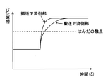
- FIG. 11 shows the temperature change of the workpiece 52 in the preheating step and the melt heating step in the manufacturing apparatus and method when the intermediate heating member 11 is not provided.
- the terminal 520 on the upstream side of conveyance in the workpiece 52 also moves from the preheating member 10 to the melting and heating member 12. Move quickly to.
- the terminal 520 on the upstream side of the conveyance can contact the molten heating member 12 for the same time as the terminal 520 on the downstream side of the conveyance.
- the conveyance upstream side intends the opposite side to the direction where the conveyance part 2 advances in a manufacturing process. Accordingly, the terminal 520 on the upstream side of conveyance indicates the terminal 520 on the left side in FIG.
- the temperature change of the terminal 520 on the upstream side of conveyance is the temperature change of the terminal 520 on the downstream side of conveyance from the start of the stop state of the preheating member 10 to the end of the halt state of the melting and heating member 12. And not much different.
- the temperature of the workpiece 52 rapidly rises in the initial stage of the stop state with respect to the melting and heating member 12, the difference in the rising time of the temperature between the terminal 520 on the upstream side of the conveyance and the terminal 520 on the downstream side of the conveyance is small.
- work 52 is small, it can suppress that the molten state of a solder becomes non-uniform
- FIG. 12 shows the temperature change of the workpiece in the preheating process and the melt heating process in the conventional manufacturing apparatus.
- the conventional manufacturing apparatus referred to here is an apparatus that conveys a workpiece at a constant speed over both the preheating area and the melt heating area, not intermittent conveyance.
- the time at which the terminal 520 on the upstream side of the work 52 receives heat from the melting and heating member is shorter than the terminal 520 on the downstream side of the work. Therefore, as shown in FIG. 12, the temperature change on the upstream side of the workpiece rises more gently than the temperature change on the downstream side of the workpiece. That is, the temperature difference in the conveyance direction in the workpiece is larger than the temperature difference shown in FIG. Due to this temperature difference, a time difference occurs in the solder in a molten state, the molten state becomes non-uniform, and defects such as tombstones are likely to occur.
- FIG. 13 shows the temperature change of the workpiece 52 in the preheating step and the melting heating step with respect to the manufacturing apparatus and method having the intermediate heating member 11 between the preheating member 10 and the melting heating member 12.
- the temperature change shown by the two-dot chain line in FIG. 13 is the temperature change when the intermediate heating member 11 shown in FIG. 11 is not provided.
- the workpiece 52 moves quickly from a stop state with respect to the preheating member 10 until it reaches a stop state with respect to the intermediate heating member 11, and further from a stop state with respect to the intermediate heating member 11 to a stop state with respect to the molten heating member 12. Move quickly.
- the terminal 520 on the upstream side of the conveyance can contact the intermediate heating member 11 for the same time as the terminal 520 on the downstream side of the conveyance.
- the temperature change of the terminal 520 on the upstream side of the conveyance is the same as that of the terminal 520 on the downstream side of the conveyance even during the period from the start of the stopped state with respect to the preheating member 10 to the end of the stopped state with respect to the intermediate heating member 11. It shows that it is not much different from temperature change.
- the intermediate heating member 11 By providing the intermediate heating member 11 in this way, the temperature of the workpiece 52 can be increased stepwise toward the melting temperature of the solder. It is also possible to suppress the stop time of the work 52 in the area.
- the electrical component manufacturing apparatus is an apparatus that manufactures electrical components by performing soldering coupling of the components with heat conducted to the workpiece 52 being conveyed.
- One of the manufacturing apparatuses includes a preheating unit that preheats the workpiece 52 that is in contact, a melting heating unit that is provided downstream of the preheating unit, a cooling unit that is provided downstream of the melting heating unit, and a preheating unit.
- a transport unit that transports the work 52 while contacting the part, the melt heating unit, and the cooling unit in this order.
- the melting and heating unit is set to a temperature that is higher than that of the preheating unit and can melt the solder, and heats the workpiece 52 that is in contact therewith.
- the conveyance unit performs intermittent conveyance in which the workpiece 52 is moved from the preheating unit to the melting and heating unit and stopped at the melting and heating unit without stopping in a state where the workpiece 52 is in contact with both the preheating unit and the melting and heating unit at the same time.
- the workpiece 52 has a structure in which the temperature is adjusted in each part while contacting the preheating part, the melt heating part, and the cooling part in this order. Since this heating method is not based on convection heating but based on heat transfer by solids, the occupied volume of the manufacturing apparatus can be suppressed.
- the conveyance unit performs intermittent conveyance in which the workpiece 52 is moved from the preheating unit to the melting heating unit without stopping in a state where the workpiece 52 is in contact with both the preheating unit and the melting heating unit at the same time. As described above, both the preheating unit and the melting heating unit simultaneously heat the workpiece 52 in a short time, and can sufficiently secure the time for heating the entire workpiece 52 in the melting heating unit.
- the manufacturing apparatus contributes to downsizing of the entire apparatus and temperature difference suppression in the workpiece 52.
- the electrical component manufacturing apparatus is provided downstream of the preheating unit and is set at a temperature that is higher than the preheating unit and at which the solder can be melted.
- a melt heating unit is provided for heating in contact.
- this manufacturing apparatus since heat is applied to the contact heating portion of the work 52 other than the soldering portion 510 with the part in the melting and heating portion, it is possible to suppress the solder from flowing excessively. By suppressing the excessive molten state of the solder, it is possible to prevent the molten solder from flowing and adhering to the molten heating member 12. This manufacturing apparatus contributes to downsizing of the entire apparatus and suppression of solder flow.
- the electrical component manufacturing apparatus further includes a contact force strengthening unit that provides a force for increasing the degree of contact between the work 52 and the melt heating unit that are stopped by the melt heating unit.
- a contact force strengthening unit that provides a force for increasing the degree of contact between the work 52 and the melt heating unit that are stopped by the melt heating unit.
- the work 52 includes a terminal 520 and an element to be soldered to the terminal 520.
- the fusion heating part is in contact with the contact heating part except the soldering part 510 with the element in the terminal 520.
- the contact heating part in the terminal 520 that is in contact with the melting and heating unit does not include the soldering part 510, the solder is melted so that the temperature of the soldering part 510 does not increase excessively. Contributes to According to this, it can suppress that the viscosity of the solder of a molten state falls too much, flows excessively, and adheres to the fusion
- the electrical component manufacturing apparatus further includes an intermediate heating unit that is provided between the preheating unit and the melt heating unit and is set to a temperature included between the temperature of the preheating unit and the temperature of the melt heating unit.
- the conveyance unit 2 performs intermittent conveyance in which the workpiece 52 is stopped in the preheating unit, moved from the preheating unit to the intermediate heating unit, and stopped in the intermediate heating unit. According to this manufacturing apparatus, the stopped workpiece 52 is moved from the preheating unit to the intermediate heating unit and stopped, and the stopped workpiece 52 is moved from the intermediate heating unit to the melting heating unit and stopped.
- the time for which the workpiece 52 is heated by both the preheating portion and the intermediate heating portion and the time for which the workpiece 52 is heated by both the intermediate heating portion and the melting heating portion can be shortened, and the entire workpiece 52 is melted by the intermediate heating portion and the melting portion.
- Sufficient time for heating in the heating section can be secured. Therefore, the heating which suppressed the temperature difference of the workpiece
- the intermediate heating unit between the preheating unit and the melt heating unit the temperature setting for heating the workpiece 52 becomes smaller, which contributes to setting the thermal change of the workpiece 52 gently.
- One method of manufacturing an electrical component includes a step of preparing solder for soldering the second element 51 to the terminal 520 and an installation step of installing the second element 51 in the soldering portion 510 of the terminal 520. carry out.
- This manufacturing method further performs a preheating step, a melt heating step, and a cooling step.
- the preheating process is a process in which, after the installation process, the preheating member 10 is stopped in a state in which the terminal 520 is in contact with the preheating member 10 having a preheating temperature lower than the solder melting temperature, and is preheated by the preheating member 10.
- the terminal 520 is transported from a stopped state in the preheating step, and stopped in a state in which the terminal 520 is brought into contact with the melting and heating member 12 that is a solder melting temperature. It is the process of heating by.
- the terminal 520 is conveyed and stopped in a state where the terminal 520 is brought into contact with the cooling member 13 which is a temperature at which the solder is solidified, and cooled by the cooling member 13, and the element is placed on the terminal 520. Join with solder.
- the temperature of the work 52 is adjusted while contacting the preheating member 10, the melting and heating member 12, and the cooling member 13 in this order, so that the occupied volume of the manufacturing apparatus can be suppressed.
- the manufacturing method is a method in which the stopped workpiece 52 is moved from the preheating member 10 to the melting heating member 12 and stopped at the melting heating member 12. For this reason, the time for which both the preheating member 10 and the fusion heating member 12 simultaneously heat the workpiece 52 is short, and the time for which the entire workpiece 52 is heated by the fusion heating member 12 can be sufficiently secured.
- This manufacturing method in the process of transporting the workpiece 52, it is possible to realize heating that suppresses the temperature difference in the transport direction in the workpiece 52, and it is possible to suppress defects such as tombstones.
- This electrical component manufacturing method contributes to downsizing of the manufacturing apparatus and temperature difference suppression in the workpiece 52.
- the preheating member 10 and the melt heating member 12 are in contact with the contact heating portion of the terminal 520 excluding the soldering portion 510.
- heat is applied to the contact heating portion of the melt heating member 12 excluding the soldered portion 510 with the second element 51 in the work 52, so that the solder is prevented from flowing excessively. Can do. Thereby, it can suppress that the solder of a molten state flows into the fusion
- This manufacturing method contributes to downsizing of the entire device and suppression of solder flow.
- the contact degree between the terminal 520 and the melting and heating member 12 can be increased as compared with the state in which the workpiece 52 is placed on and in contact with the melting and heating member 12. Due to this effect, the heat of the melting and heating member 12 is efficiently transferred to the terminal 520, which contributes to more surely performing the soldering connection between the terminal 520 and the second element 51.
- a gap is provided between the adjacent preheating member 10 and the melt heating member 12.
- a gap is provided between the adjacent intermediate heating member 11 and the melt heating member 12.
- a gap may be provided between the adjacent melt heating member 12 and the cooling member 13, or a gap may be provided between the adjacent preheating member 10 and the intermediate heating member 11.
- the preheating member 10 includes a corner portion 10a1 having a surface shape in which the upper surface 10a is lowered toward the conveyance downstream end surface 10b facing the adjacent intermediate heating member 11 and the melt heating member 12.
- the intermediate heating member 11 includes a corner portion 11a1 having a surface shape in which the upper surface 11a becomes lower toward the conveyance downstream end surface 11b facing the adjacent melting heating member 12.
- the intermediate heating member 11 includes a corner portion having a surface shape in which the upper surface 11a is lowered toward the upstream end surface of the conveyance facing the adjacent preheating member 10.
- the melting and heating member 12 includes a corner portion 12a1 having a surface shape in which the upper surface 12a becomes lower toward the upstream conveying end surface 12b facing the adjacent preheating member 10 and intermediate heating member 11.
- These corners can be formed in a curved surface shape or a chamfered shape. These corners are set to dimensions that allow the workpiece 52 to be conveyed stably and smoothly on the production line 1.
- the manufacturing apparatus of the second embodiment when the work 52 is transported by the transport unit 2, it contributes to smoothly sliding the work 52 between adjacent members in the manufacturing line 1. Therefore, according to 2nd Embodiment, the manufacturing apparatus excellent in productivity can be provided.
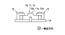
- each of the preheating member 10, the intermediate heating member 11, and the melting heating member 12 is fixed to the base member 14 on one side or the other side in the transport direction.
- Each of the preheating member 10, the intermediate heating member 11, and the melt heating member 12 includes a fixing portion 15 that is fixed to the pedestal member 14 in the vicinity of the transport downstream end or the transport upstream end.
- the fixing portion 15 is provided at one place in the transport direction. Therefore, each of the preheating member 10, the intermediate heating member 11, and the fusion heating member 12 is fixed to the pedestal member 14 at only one place in the transport direction.
- the restraint site for the base member 14 in each member is one in the transport direction. Deformation due to thermal expansion can be missed. Therefore, it is possible to avoid a large deformation of the contact surface with the workpiece 52, and it is possible to provide a manufacturing apparatus that can ensure heat transfer performance to the workpiece 52.
- the workpiece 52 has two terminals 520 arranged in the horizontal direction, but the number of terminals is not limited to two.
- the work 52 may be configured to have one or three or more terminals.
- the pressing device 3 is included in a contact force strengthening unit that provides a force that increases the degree of contact between the workpiece 52 and the fusion heating unit.
- the contact force strengthening portion in the manufacturing apparatus is not limited to the configuration in which the workpiece 52 is pressed against the melting and heating portion as in the pressing device 3.
- the contact force strengthening unit may be configured to attract the workpiece 52 to the melting and heating unit by suction force or the like.
- the pressing device 3 in the above-described embodiment may be configured to provide a force that increases the degree of contact with the workpiece 52 not only in the melting and heating unit but also in other areas. Thereby, the contact degree with the workpiece
Landscapes
- Engineering & Computer Science (AREA)
- Mechanical Engineering (AREA)
- Manufacturing & Machinery (AREA)
- Microelectronics & Electronic Packaging (AREA)
- Electric Connection Of Electric Components To Printed Circuits (AREA)
Abstract
この製造装置は、接触しているワーク(52)を予熱する予熱部材(10)と、予熱部材(10)よりも搬送下流に設けられる溶融加熱部材(12)と、溶融加熱部材(12)よりも搬送下流に設けられて、ワーク(52)を冷却する冷却部材(13)を備える。製造装置はさらに予熱部材(10)、溶融加熱部材(12)、冷却部材(13)の順に接触させながらワーク(52)を搬送する搬送部材を備える。溶融加熱部材(12)は、はんだが溶融可能な温度に設定されてワーク(52)を加熱する。搬送部は、ワーク(52)が予熱部材(10)と中間加熱部材(11)の両方に同時に接触した状態で停止することなく、さらに中間加熱部材11と溶融加熱部材12の両方に同時に接触した状態で停止することなくワーク52を移動させる間欠搬送を行う。製造装置の小型化とワークにおける温度差の抑制とを図ることができる。
Description
本出願は、当該開示内容が参照によって本出願に組み込まれた、2018年2月2日に出願された日本特許出願2018-017400号を基にしている。
この明細書における開示は、電気部品製造装置および電気部品の製造方法に関する。
特許文献1には、ワークを搬送するコンベアと、ワークに予備加熱および本加熱を施してはんだ付処理した後、冷却するはんだ処理部と、炉を形成する本体部とを有するリフロー炉が記載されている。予備加熱ゾーンのコンベアの上部および下部には熱風発生部が設置され、本加熱ゾーンのコンベアの上部および下部にも熱風発生部が設置されている。
特許文献2には、ワークを搬送するコンベアベルトを通して、ヒータブロックの熱をワークに移動させてワークを加熱することにより、伝導される熱によりリフローはんだ付を行う装置が記載されている。この装置は、ワークを予熱するプリヒート用ヒータブロックと、プリヒート用ヒータブロックの下流側でワークに塗布されたソルダペーストを溶融するリフロー用ヒータブロックと、ワーク冷却速度調整用ヒータブロックと、ワーク冷却用ブロックとを備える。ワーク冷却速度調整用ヒータブロックはリフロー用ヒータブロックの下流側でワークの冷却速度を遅らせるように加熱調節することでワークを緩やかに冷却する。ワーク冷却用ブロックはワーク冷却速度調整用ヒータブロックの下流側でワークを急速に冷却する。
特許文献1の装置は、熱風発生装置とリフロー炉とを有するため、製造装置の大型になりやすいという課題がある。
特許文献2の装置は特許文献1の装置に比べて小型化できる。しかし、特許文献2では、プリヒート用ヒータブロックのエリアとリフロー用ヒータブロックのエリアにおいてワークをコンベアで連続的に搬送するため、ワークが温度差のあるエリアをまたいだ状態で加熱される。この加熱状態により、搬送方向においてワークの温度差が大きくなりやすい。このため、ワークにおいて溶融するはんだの表面張力に差が生じてツームストーン現象が発生するという課題がある。また、特許文献2に記載の装置では、溶融したはんだが流動してヒータブロックに付着するという課題がある。
この明細書に開示する一つの目的は、製造装置の小型化とワークにおける温度差の抑制とを図る電気部品製造装置および電気部品の製造方法を提供することである。
この明細書に開示する一つの目的は、製造装置の小型化とはんだの流動抑制とを図る電気部品製造装置および電気部品の製造方法を提供することである。
開示された電気部品製造装置の一つは、搬送されるワークに伝導する熱により部品のはんだ付結合を実施して電気部品を製造する装置であり、接触しているワークを予熱する予熱部と、予熱部よりも搬送下流に設けられ予熱部よりも高温であってはんだが溶融可能な温度に設定されて、接触しているワークを加熱する溶融加熱部と、溶融加熱部よりも搬送下流に設けられて、接触しているワークを冷却する冷却部と、ワークを支持して、予熱部、溶融加熱部、冷却部の順に接触させながらワークを搬送する搬送部と、を備え、搬送部は、ワークが予熱部と溶融加熱部の両方に同時に接触した状態で停止することなくワークを予熱部から溶融加熱部へ移動させ、溶融加熱部において停止させる間欠搬送を行う。
開示された電気部品製造装置によれば、ワークは予熱部、溶融加熱部、冷却部の順に接触しながら各部において温度調節される構造であるので、製造装置の占有容積を抑えることができる。搬送部は、ワークが予熱部と溶融加熱部の両方に同時に接触した状態で停止することなくワークを予熱部から溶融加熱部へ移動させて溶融加熱部において停止させる間欠搬送を行う。このため、予熱部と溶融加熱部の両方が同時にワークを加熱する時間が短く、ワークを溶融加熱部で加熱する時間を十分に確保できる。これにより、ワークの搬送過程において、ワークにおける搬送方向の温度差を抑えるようなワークの加熱を実現できる。このように電気部品製造装置は、製造装置の小型化とワークにおける温度差の抑制効果とを提供することができる。
開示された電気部品製造装置の一つは、搬送されるワークに伝導する熱により部品のはんだ付結合を実施して電気部品を製造する装置であり、ワークに接触して予熱する予熱部と、予熱部よりも搬送下流に設けられ予熱部よりも高温であってはんだが溶融可能な温度に設定されて、ワークにおける部品とのはんだ付部を除く接触加熱部位に接触して加熱する溶融加熱部と、溶融加熱部よりも搬送下流に設けられて接触しているワークを冷却する冷却部と、ワークを支持して予熱部、溶融加熱部、冷却部の順に接触させながらワークを搬送する搬送部と、を備える。
開示された電気部品製造装置によれば、ワークは予熱部、溶融加熱部、冷却部の順に接触しながら各部において温度調節される構造であるため、製造装置の占有容積を抑えることができる。溶融加熱部は、ワークにおける部品とのはんだ付部を除く接触加熱部位に熱を与えるため、溶融状態のはんだが大きく流動することを抑えて、溶融状態のはんだが溶融加熱部側に流れてしまうことを抑制できる。このように電気部品製造装置は、製造装置の小型化とはんだの流動抑制とを提供することができる。
開示された電気部品の製造方法の一つは、ターミナルに素子をはんだ付結合するためのはんだを準備する工程と、素子をターミナルにおけるはんだ付部に設置する設置工程と、設置工程の後、はんだの溶融可能温度よりも低い予熱温度である予熱部材にターミナルを接触させた状態で停止させて、予熱部材によって予熱する予熱工程と、予熱工程の後、ターミナルを予熱工程における停止状態から搬送して、はんだの溶融可能温度である溶融加熱部材にターミナルを接触させた状態で停止させて、溶融加熱部材によって加熱する溶融加熱工程と、溶融加熱工程の後、ターミナルを搬送してはんだが固化する温度である冷却部材にターミナルを接触させた状態で停止させて冷却部材によって冷却して、ターミナルに素子をはんだ付結合する冷却工程と、を実施する。
開示された電気部品の製造方法によれば、ワークを予熱部材、溶融加熱部材、冷却部材の順に接触させながら各部において温度調節するので、製造装置の占有容積を抑えることができる。さらに、停止状態のワークを予熱部材から溶融加熱部材へ移動させ溶融加熱部材において停止させる製造方法であるため、予熱部材と溶融加熱部材の両方が同時にワークを加熱する時間が短く、ワークを溶融加熱部材で加熱する時間を十分に確保できる。この製造方法によれば、ワークの搬送過程において、ワークにおける搬送方向の温度差を抑えるようなワークの加熱を実現できる。この電気部品の製造方法は、製造装置の小型化とワークにおける温度差の抑制効果とを提供することができる。
以下に、図面を参照しながら本開示を実施するための複数の形態を説明する。各形態において先行する形態で説明した事項に対応する部分には同一の参照符号を付して重複する説明を省略する場合がある。各形態において構成の一部のみを説明している場合は、構成の他の部分については先行して説明した他の形態を適用することができる。各実施形態で具体的に組合せが可能であることを明示している部分同士の組合せばかりではなく、特に組合せに支障が生じなければ、明示してなくとも実施形態同士を部分的に組み合せることも可能である。
(第1実施形態)
第1実施形態について、図1~図13を参照して説明する。第1実施形態では、明細書に開示の目的を達成可能な電気部品製造装置や製造方法の一例を説明する。この電気部品製造装置や製造方法では、熱伝導性を有する部位同士をはんだ付結合する構成を有するワークを含む電気部品を製造することができる。この電気部品製造装置や製造方法では、例えば、導電性を有するターミナルに部品の端子がはんだ付結合されたワークを含む電気部品を製造することができる。このワークは、部品が搭載されたターミナル、または部品が搭載された電気部品とも称することができる。この電気部品は、ターミナルにはんだ付結合されている単数または複数の素子を有することができる。この電気部品は、例えば半導体デバイスを含むが、このような製品に限定されない。
第1実施形態について、図1~図13を参照して説明する。第1実施形態では、明細書に開示の目的を達成可能な電気部品製造装置や製造方法の一例を説明する。この電気部品製造装置や製造方法では、熱伝導性を有する部位同士をはんだ付結合する構成を有するワークを含む電気部品を製造することができる。この電気部品製造装置や製造方法では、例えば、導電性を有するターミナルに部品の端子がはんだ付結合されたワークを含む電気部品を製造することができる。このワークは、部品が搭載されたターミナル、または部品が搭載された電気部品とも称することができる。この電気部品は、ターミナルにはんだ付結合されている単数または複数の素子を有することができる。この電気部品は、例えば半導体デバイスを含むが、このような製品に限定されない。
第1実施形態において開示する電気部品製造装置や製造方法は、ワーク52に固定物を接触させて固体物からの熱移動によってワーク52を直接加熱し、はんだ付部510に設けられたはんだを溶融する。したがって、この製造装置や製造方法は、ワーク52が固体間の熱伝達によって加熱される方式である。この製造装置や製造方法による製造物である電気部品の一例として、第1実施形態では図1および図2に図示するような電気部品5を開示する。
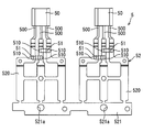
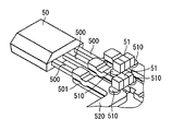
電気部品5は、ワーク52と、ワーク52に溶接接合された第1素子50とを備えている。ワーク52は、第2素子51と第2素子51が搭載されたターミナル520とを含む。第1素子50は、導電性を有しターミナル520側に延びる複数の端子500を備える。第1素子50は、端子500がターミナル520に溶接接合されている構成によってターミナル520に結合されている。この溶接結合は、第2素子51とターミナル520とのはんだ付結合を実施する前に完了している。つまり、第2素子51をターミナル520の所定位置に設置する状態では、すでに端子500はターミナル520に溶接接合されている。
図1に示すように、ワーク52は横方向に並ぶ2個のターミナル520を有している。ターミナル520は、例えば導電性の平板を打ち抜き加工して形成した板状の部材である。ワーク52は、2個のターミナル520を一端側で連結する連結部521を有している。連結部521は、2個のターミナル520の並び方向に延びる板状部分である。連結部521には、2個のターミナル520の並び方向に並ぶ2個の孔部521aが設けられている。孔部521aは、ワーク52を製造ライン1上に搬送するために支持装置21によって支持される被支持部である。
各ターミナル520は、第1素子50と第2素子51とが結合されている。第1素子50は、例えば、半導体集積回路等の電子回路を構成する部品である。第2素子51は、例えば、セラミックコンデンサ等のチップコンデンサである。第2素子51は、導電部がターミナル520のはんだ付部510にはんだ付結合されている構成によってターミナル520と一体になっている。はんだ付部510には、はんだ材料が付着または被覆されている。第2素子51は、はんだ付部510を介してターミナル520に載置されるように電気部品5に設けられている。第2素子51は、ターミナル520において、孔部521aである被支持部とは離れた反対側に設けられている。
ターミナル520には、製造工程のうちはんだを溶融する工程において溶融加熱部材12との接触度合を高めるために溶融加熱部材12にターミナル520を押しつける際に、製造装置によって押さえられる被押圧部が設けられている。この被押圧部は孔部521aとはんだ付部510との間に位置している。連結部521はターミナル520の一端側に設けられ、第2素子51はターミナル520の他端側に結合されている。第1素子50および溶接接合部501は、第2素子51およびはんだ付部510よりもターミナル520において他方側に設けられていることが好ましい。この構成により、連結部521、被押圧部、はんだ付部510、溶接接合部501は、ターミナル520一方側から他方側にかけてこの順に位置している。
はんだ付部510は、板状のターミナル520において、第1素子50の端子500が溶接接合されている溶接接合部501を含む面とは反対側の面に設けられている。したがって、はんだ付部510は溶接接合面の裏面に設けられている。各ターミナル520には、ターミナル520の並び方向や端子500の延びる方向に並ぶ2個の第2素子51が搭載されている。
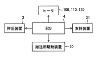
次に図3~図9を参照しながら製造装置および製造方法について説明する。製造装置は、ワーク52がスライド移動する製造ライン1と、ワーク52を製造ライン1に押し付けるための押圧装置3と、ワーク52を製造ライン1上で搬送する搬送部2と、を備えている。図3に示すように、製造装置の運転をつかさどる制御装置4は、製造ライン1における各部材の温度を調節するためにヒータ100、ヒータ110、ヒータ120を制御する電子式の制御装置である。ヒータ100は、製造ライン1における予熱部材10の温度を調節する発熱装置である。ヒータ110は、製造ライン1における中間加熱部材11の温度を調節する発熱装置である。ヒータ120は、製造ライン1における溶融加熱部材12の温度を調節する発熱装置である。予熱部材10、中間加熱部材11、溶融加熱部材12を加熱する装置は、各部材を直接に加熱する手段であればよく、前述のヒータに限定するものではない。
製造ライン1には、気化したフラックスを回収するために、予熱部材10、中間加熱部材11、溶融加熱部材12等の上面と回収部とを連通させる回収通路が設けられている。回収通路には、吸入用の送風機等による吸引力が作用するように構成されている。この構成によれば、予熱部材10、中間加熱部材11、溶融加熱部材12等の上方に漂う気化したフラックスを回収通路に引き込み、回収部の内部に排出して集めることができる。
さらに制御装置4は、押圧装置3の動作、支持装置21の動作、搬送用駆動装置20の駆動力を制御するように構成されている。制御装置4は、制御対象部品の作動を制御するハードウェアおよびソフトウェアを有する。制御装置4は、プログラムに従って動作するマイコンのようなデバイスを主なハードウェア要素として備える。
押圧装置3は、製造方法のはんだを溶融する工程において、ターミナル520を熱源に押し付ける外力をワーク52に与える装置である。押圧装置3は、柱状の押圧部30を製造ライン1に近づけたり離間させたりするように駆動して、ターミナル520の中心付近に位置する被押圧部およびその周囲を適切な圧力で押さえることができる。押圧装置3は、押圧部30がターミナル520を製造ライン1に押し付ける接触状態と、押圧部30がターミナル520から離間した非接触状態とにわたって制御されるアクチュエータを有する。接触状態の動作により、ターミナル520と製造ライン1との接触度合が高まるため、押圧装置3は、ワーク52と製造ライン1との接触度合を高める力を提供する接触力強化部の一例である。
支持装置21は、製造方法において、ワーク52を製造ライン1上で移動させるためにターミナル520を支持する装置である。支持装置21は、製造ライン1の側方をスライド移動する搬送部2に設けられたピン状部がターミナル520における孔部521aに嵌ることによってターミナル520を支持することができる。搬送用駆動装置20は、搬送部2を製造ライン1に沿う方向に搬送する駆動力を提供する装置である。搬送用駆動装置20は、支持装置21がターミナル520を支持した状態である搬送部2を駆動する。搬送用駆動装置20は、所定の送り速度、所定の送り距離、所定の停止時間にしたがってワーク52をステップ送りする間欠搬送を行うように、搬送部2を駆動するアクチュエータを有する。この動作により、はんだが溶融する工程においてターミナル520において大きな温度差が生じないようにでき、ワーク52におけるはんだ付結合状態に不具合が生じないような製造を実施できる。
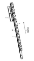
図4は、製造ライン1を理解しやすくするために、搬送部2を除いた状態の製造装置を示している。図5は、図4に搬送部2を追加して、正規の製造装置を示している。製造ライン1上には、多数のワーク52が搬送部2の搬送方向に並んで配置されている。製造ライン1上に並んでいる多数のワーク52は、図5に示す搬送部2によって、停止状態から所定ピッチずつ搬送方向に送られた後、再び所定時間停止する。この実施形態の例では、最も搬送方向寸法が短い中間加熱部の寸法に合わせて、ワーク52を2個ずつまたは1個ずつ送る所定ピッチに設定されている。このような送りピッチによれば、製造工程において、ワーク52が隣接する2つエリアにまたがって停止するような事態を回避している。
製造ライン1は、予熱部、中間加熱部、溶融加熱部、冷却部を備えている。予熱部は、接触しているワーク52を予熱する予熱部材10を備えている。予熱部材10は、ターミナル520の温度をはんだが溶融する温度に上げる前に予備加熱するエリアを構成し、予備加熱時間を確保するために溶融加熱部よりも搬送方向に長い寸法となるように設定されている。予熱部材10は、ヒータ100によって、例えば140℃~180℃の範囲の温度に設定されている。
中間加熱部は、予熱部よりも搬送下流に設けられている。搬送下流とは、製造工程で搬送部2が進行する方向に、より進んだ位置のことを意図している。中間加熱部は、接触しているワーク52を予熱部よりも高い温度に加熱する中間加熱部材11を備えている。中間加熱部材11は、ターミナル520の温度をはんだ溶融可能温度に近づけるエリアを構成し、予熱部や溶融加熱部よりも搬送方向に短い寸法となるように設定されている。中間加熱部材11は、予熱部の温度と溶融加熱部の温度との間に含まれる温度に設定されており、ヒータ110によって、例えば180℃~220℃の範囲の温度に設定されている。
溶融加熱部は、予熱部や中間加熱部よりも搬送下流に設けられている。溶融加熱部は、接触しているワーク52を予熱部や中間加熱部よりも高い温度に加熱する溶融加熱部材12を備えている。溶融加熱部材12は、接触しているターミナル520の温度をはんだが溶融可能な温度になるように、ヒータ110によって、例えば230℃~250℃の範囲の温度に設定されている。つまり、はんだ付部510に設けられたはんだは、ターミナル520がこの温度範囲に制御された場合に溶融する材料である。例えば、はんだには溶融温度が217℃となる材料が用いられている。
図7は、溶融加熱部で停止している状態のすべてのワーク52に対して、押圧装置3が押圧力を提供する直前の状態を示している。この状態では、押圧部30は対応するワーク52の中心付近の直上に位置している。この後、溶融加熱部で停止している状態のすべてのワーク52は、押圧装置3によって溶融加熱部材12に押し付けられている。これにより、溶融加熱部材12とワーク52との接触度合が強化されて、固体間の熱伝達の効率を高めることができる。
冷却部は、溶融加熱部よりも搬送下流に設けられている。冷却部は、接触しているワーク52を冷却する冷却部材13を備えている。冷却部材13は、接触しているターミナル520の温度をはんだが固化する温度になるように、例えば内部を流通する流体の吸熱作用によって制御されている。
図4等に例示された製造装置は、この実施形態で説明するワーク52の個数、停止時間、移動時間に限定されず、多様な組み合わせによって構成することができる。例えば、予熱部材10、中間加熱部材11、溶融加熱部材12および冷却部材13は、搬送方向の長さが異なるものの同様の横断面形状を有するブロック状態で形成されており、この順に隣接して連なることによって製造ライン1を形成している。製造工程において、予熱部材10には20個のワーク52が配置され、中間加熱部材11には2個のワーク52が配置され、溶融加熱部材12には10個のワーク52が配置され、冷却部材13には2個のワーク52が配置されるようになっている。また、製造ライン1は、中間加熱部材11を除いた、予熱部材10、溶融加熱部材12および冷却部材13によって構成することもできる。
図6および図8は、製造装置においてワーク52が搬送部2によって支持されている状態を示している。搬送部2は、支持装置21のピン状部が孔部521aに下方から嵌った状態によって各ワーク52を支持している。ピン状部は、搬送方向について各ターミナル520に対応する位置で連結部521を支持している。したがって、支持装置21は1個のワーク52について搬送方向に並ぶ2箇所で支持している。孔部521aはその内径がピン状部の外径よりも大きくなるように形成されている。このため、ピン状部が孔部521aに嵌った状態で、ピン状部と孔部521aとの間にクリアランスが生じ、支持装置21がワーク52を支持する工程を円滑に実施することに貢献できる。
図6に示すように、製造装置は複数の搬送部2を有し、各搬送部2は搬送方向に並ぶ4個のワーク52を支持している。溶融加熱部材12は、ターミナル520において第2素子51とのはんだ付部510を除く接触加熱部位に接触している。図8および図9に示すように、この接触加熱部位は、ターミナル520において溶融加熱部材12の上面12aと接触する部分である。この接触加熱部位は、ターミナル520において、はんだ付部510と連結部521との間の範囲である。したがって、はんだ付部510と第1素子50および溶接接合部501は、この接触加熱部位の外に位置している。
電気部品を製造する方法は、ターミナル520に第2素子51をはんだ付結合するためのはんだを準備する準備工程、第2素子51をターミナル520におけるはんだ付部510に設置する設置工程、予熱工程、中間加熱工程、溶融加熱工程、および冷却工程を備える。準備工程は、すでに第1素子50が溶接接合されたターミナル520に対してはんだ付部510にはんだを設置する工程である。設置工程は、製造ライン1上に載置するすべてのワーク52について、はんだ付部510に第2素子51の導電部が接触するように第2素子51を所定の位置に設置する工程である。
予熱工程は、設置工程の後、はんだの溶融可能温度よりも低い予熱温度に設定した予熱部材10にターミナル520を接触させた状態で停止させて予熱部材10によって予熱する。予熱工程では、ワーク52を1個分ずつステップ送りし、例えば停止状態から移動を開始後、4秒間経過するまで停止する。したがって、各ワーク52は予熱工程において80秒間予熱されることになる。中間加熱工程は、予熱工程の後、ターミナル520を予熱工程における停止状態から搬送して、予熱温度とはんだの溶融可能温度との間の温度に設定した中間加熱部材11にターミナル520を接触させた状態で停止させて加熱する。中間加熱工程でもワーク52を1個分ずつステップ送りし、例えば停止状態から移動を開始後、4秒間経過するまで停止するので、各ワーク52は中間加熱工程において8秒間加熱されることになる。
溶融加熱工程は、中間加熱工程の後、ターミナル520を中間加熱部材工程における停止状態から搬送して、はんだの溶融可能温度に設定した溶融加熱部材12にターミナル520を接触させた状態で停止させて溶融加熱部材12によって加熱する。溶融加熱工程でもワーク52を1個分ずつステップ送りし、例えば停止状態から移動を開始後、4秒間経過するまで停止するので、各ワーク52は溶融加熱工程において40秒間加熱されることになる。冷却工程は、溶融加熱工程の後、ターミナル520を溶融加熱工程における停止状態から搬送して、はんだが固化する温度である冷却部材13にターミナル520を接触させた状態で停止させて冷却部材13によって冷却する。冷却工程でもワーク52を1個分ずつステップ送りし、例えば停止状態から移動を開始後、4秒間経過するまで停止するので、各ワーク52は冷却工程において8秒間冷却されることになる。
各工程において搬送部2の動作を制御することにより、製造ライン1上のすべてのワーク52を同時に所定ピッチ分ステップ送りした後、所定時間停止させ、再び所定ピッチ分ステップ送り後所定時間停止することを繰り返す。つまり、搬送部2は、図10において破線で示したワーク52から実線で示したワーク52へ短時間でワーク52をステップ送りすることを繰り返す。この搬送部2の動作によればワーク52は温度の異なる部材間を短時間で通過するため、各ワーク52が予熱部材10と中間加熱部材11の両方に同時に接触した状態で停止しないし、中間加熱部材11と溶融加熱部材12の両方に同時に接触した状態で停止しない。つまり、製造工程を通じてワーク52は、図10において二点鎖線で示したワーク52の位置に停止することがない。これにより、製造工程を通じて各ワーク52の温度が搬送方向について大きくばらつくような事態を回避できる。
図11は、中間加熱部材11を有していない場合の製造装置および方法において、予熱工程と溶融加熱工程とにおけるワーク52の温度変化を示している。この製造装置の場合、ワーク52は予熱部材10に対する停止状態から溶融加熱部材12に対する停止状態になるまで速やかに移動するので、ワーク52における搬送上流側のターミナル520も予熱部材10から溶融加熱部材12へ迅速に移動する。この間欠搬送により、搬送上流側のターミナル520は搬送下流側のターミナル520と同程度の時間、溶融加熱部材12に接触することができる。なお、搬送上流側とは、製造工程で搬送部2が進行する方向とは反対側を意図している。したがって、搬送上流側のターミナル520は、図8において左側のターミナル520のことを示している。
図11に示すように、予熱部材10に対する停止状態の開始から溶融加熱部材12に対する停止状態を終了するまでの間、搬送上流側のターミナル520の温度変化は、搬送下流側のターミナル520の温度変化とあまり変わらないことを示している。溶融加熱部材12に対する停止状態の初期にワーク52の温度は急上昇するが、搬送上流側のターミナル520と搬送下流側のターミナル520とは、温度の立ち上がり時間の差が小さくなっている。これにより、ワーク52の搬送方向におけるはんだ溶融の時間差が小さく、はんだの溶融状態が不均一になることを抑制でき、はんだ付結合を良好に実施することに寄与する。
これに対して、図12は従来の製造装置において、予熱工程と溶融加熱工程とにおけるワークの温度変化を示している。ここでいう従来の製造装置は、間欠搬送ではなく、予熱エリアと溶融加熱エリアとの両方にわたって一定の速度でワークを搬送する装置である。この製造装置の場合、ワーク52における搬送上流側のターミナル520は、搬送下流側のターミナル520よりも溶融加熱部材から受熱する時間が短くなる。したがって、図12に示すように、ワークにおいて搬送上流側部の温度変化が搬送下流側部の温度変化よりもなだらかに立ち上がっている。つまり、ワークにおいて搬送方向の温度差が、図11に示す温度差よりも大きいことを示している。この温度差により、はんだが溶融状態となるのに時間差が生じて溶融状態が不均一になり、ツームストーンなどの不具合が発生しやすくなる。
図13は、予熱部材10と溶融加熱部材12との間に中間加熱部材11を有している製造装置および方法に関して、予熱工程と溶融加熱工程とにおけるワーク52の温度変化を示している。図13において二点鎖線で示している温度変化は、図11に示した、中間加熱部材11を有していない場合の温度変化である。この製造装置の場合、ワーク52は予熱部材10に対する停止状態から中間加熱部材11に対する停止状態になるまで迅速に移動し、さらに中間加熱部材11に対する停止状態から溶融加熱部材12に対する停止状態になるまで迅速に移動する。この間欠搬送により、搬送上流側のターミナル520は搬送下流側のターミナル520と同程度の時間、中間加熱部材11に接触することができる。
図13に示すように、予熱部材10に対する停止状態の開始から中間加熱部材11に対する停止状態を終了するまでの間においても、搬送上流側のターミナル520の温度変化は、搬送下流側のターミナル520の温度変化とあまり変わらないことを示している。このように中間加熱部材11を備えることにより、ワーク52の温度を、はんだの溶融可能温度に向けてさらに段階的に上昇させることができるので、はんだが溶融する温度により到達しやく、また溶融加熱エリアにおけるワーク52の停止時間を抑えることも可能にする。
次に第1実施形態がもたらす作用、効果について説明する。第1実施形態の電気部品製造装置は、搬送されるワーク52に伝導する熱により部品のはんだ付結合を実施して電気部品を製造する装置である。この製造装置の一つは、接触しているワーク52を予熱する予熱部と、予熱部よりも搬送下流に設けられる溶融加熱部と、溶融加熱部よりも搬送下流に設けられる冷却部と、予熱部、溶融加熱部、冷却部の順に接触させながらワーク52を搬送する搬送部とを備える。溶融加熱部は、予熱部よりも高温であってはんだが溶融可能な温度に設定されて、接触しているワーク52を加熱する。搬送部は、ワーク52が予熱部と溶融加熱部の両方に同時に接触した状態で停止することなくワーク52を予熱部から溶融加熱部へ移動させ、溶融加熱部において停止させる間欠搬送を行う。
この製造装置によれば、ワーク52は予熱部、溶融加熱部、冷却部の順に接触しながら各部において温度調節される構造である。この加熱方式は、対流加熱でなく固体による熱伝達によるものであるので、製造装置の占有容積を抑えることができる。搬送部は、ワーク52が予熱部と溶融加熱部の両方に同時に接触した状態で停止することなくワーク52を予熱部から溶融加熱部へ移動させる間欠搬送を行う。このように予熱部と溶融加熱部の両方が同時にワーク52を加熱する時間が短く、溶融加熱部でワーク52全体を加熱する時間を十分に確保できる。これにより、はんだの溶融過程において、ワーク52における搬送方向の温度差を抑えるようなワーク52の加熱を実現でき、例えばツームストーンなどの不具合を抑制できる。このように製造装置は、装置全体の小型化とワーク52における温度差抑制とに寄与する。
電気部品製造装置は、予熱部よりも搬送下流に設けられ予熱部よりも高温であってはんだが溶融可能な温度に設定されて、ワーク52における部品とのはんだ付部510を除く接触加熱部位に接触して加熱する溶融加熱部を備える。
この製造装置によれば、溶融加熱部において、ワーク52における部品とのはんだ付部510を除く接触加熱部位に熱を与えるので、はんだが過剰に流動する状態になることを抑えることができる。はんだの過剰な溶融状態を抑えることにより、溶融状態のはんだが溶融加熱部材12に流れて付着してしまうことを抑制できる。この製造装置は、装置全体の小型化とはんだの流動抑制とに寄与する。
電気部品製造装置は、溶融加熱部で停止している状態であるワーク52と溶融加熱部との接触度合を高める力を提供する接触力強化部をさらに備える。この製造装置によれば、ワーク52が溶融加熱部に載置されて接触している状態に比べて、ターミナル520と溶融加熱部との接触度合を高めることができる。この効果により、溶融加熱部の熱をターミナル520に効率的に熱伝達させることができるので、はんだの溶融状態を所望の状態にして、より確実なはんだ付結合を実施することに寄与する。
ワーク52は、ターミナル520と、ターミナル520にはんだ付結合される素子とを含んでいる。溶融加熱部は、ターミナル520において素子とのはんだ付部510を除く接触加熱部位に接触している。この製造装置によれば、溶融加熱部と接触しているターミナル520における接触加熱部位は、はんだ付部510を含んでいないので、はんだ付部510の温度が過剰に上がりすぎないようにはんだを溶融させることに寄与する。これによれば、溶融状態のはんだの粘性が下がりすぎて過剰に流動して溶融加熱部材12に付着することを抑制できる。
電気部品製造装置は、予熱部と溶融加熱部との間に設けられ、予熱部の温度と溶融加熱部の温度との間に含まれる温度に設定されている中間加熱部をさらに備える。搬送部2は、ワーク52を、予熱部において停止させ、予熱部から中間加熱部へ移動させ、中間加熱部において停止させる間欠搬送を行う。この製造装置によれば、停止状態のワーク52を予熱部から中間加熱部に移動させて停止し、さらに停止状態のワーク52を中間加熱部から溶融加熱部に移動させて停止する。これにより、ワーク52が予熱部と中間加熱部の両方で加熱される時間や中間加熱部と溶融加熱部の両方で加熱される時間を短くすることができ、ワーク52全体を中間加熱部や溶融加熱部で加熱する時間を十分に確保できる。したがって、搬送方向についてワーク52の温度差を抑えた加熱を実施でき、例えばツームストーンなどの不具合を抑制できる。さらに、予熱部と溶融加熱部との間に中間加熱部を備えることにより、ワーク52を加熱する温度設定がより小刻みになるので、ワーク52の熱変化を緩やかに設定することに寄与する。
電気部品の製造方法の一つは、ターミナル520に第2素子51をはんだ付結合するためのはんだを準備する工程と、第2素子51をターミナル520におけるはんだ付部510に設置する設置工程とを実施する。この製造方法は、さらに予熱工程と溶融加熱工程と冷却工程とを実施する。予熱工程は、設置工程の後、はんだの溶融可能温度よりも低い予熱温度である予熱部材10にターミナル520を接触させた状態で停止させて、予熱部材10によって予熱する工程である。溶融加熱工程は、予熱工程の後、ターミナル520を予熱工程における停止状態から搬送して、はんだの溶融可能温度である溶融加熱部材12にターミナル520を接触させた状態で停止させて溶融加熱部材12によって加熱する工程である。冷却工程は、溶融加熱工程の後、ターミナル520を搬送してはんだが固化する温度である冷却部材13にターミナル520を接触させた状態で停止させて冷却部材13によって冷却してターミナル520に素子をはんだ付結合する。
この製造方法によれば、ワーク52を予熱部材10、溶融加熱部材12、冷却部材13の順に接触させながら温度調節するので、製造装置の占有容積を抑えることができる。さらに製造方法は、停止状態のワーク52を予熱部材10から溶融加熱部材12へ移動させ溶融加熱部材12において停止させる方法である。このため、予熱部材10と溶融加熱部材12の両方が同時にワーク52を加熱する時間が短く、ワーク52全体が溶融加熱部材12で加熱されている時間を十分に確保できる。この製造方法によれば、ワーク52の搬送過程において、ワーク52において搬送方向の温度差を抑える加熱を実現でき、例えばツームストーンなどの不具合を抑制できる。この電気部品の製造方法は、製造装置の小型化とワーク52における温度差抑制とに寄与する。
予熱工程および溶融加熱工程において、予熱部材10および溶融加熱部材12は、ターミナル520におけるはんだ付部510を除く接触加熱部位に接触する。この製造方法によれば、溶融加熱部材12において、ワーク52における第2素子51とのはんだ付部510を除く接触加熱部位に熱を与えるので、はんだが過剰に流動する状態になることを抑えることができる。これにより、溶融状態のはんだが溶融加熱部材12に流れて付着してしまうことを抑制できる。この製造方法は、装置全体の小型化とはんだの流動抑制とに寄与する。
溶融加熱工程においては、溶融加熱部材12で停止している状態であるワーク52と溶融加熱部材12との接触度合を高める外力を提供する。この製造方法によれば、ワーク52が溶融加熱部材12に載置されて接触している状態に比べて、ターミナル520と溶融加熱部材12との接触度合を高めることができる。この効果により、溶融加熱部材12の熱がターミナル520に効率的に熱伝達するので、ターミナル520と第2素子51とのはんだ付結合をより確実に実施することに寄与する。
(第2実施形態)
第2実施形態について図14を参照して説明する。第2実施形態において、第1実施形態に係る図面と同一符号を付した構成部品および説明しない構成は、第1実施形態と同様であり、同様の作用効果を奏する。第2実施形態では、第1実施形態との相違点のみ説明する。
第2実施形態について図14を参照して説明する。第2実施形態において、第1実施形態に係る図面と同一符号を付した構成部品および説明しない構成は、第1実施形態と同様であり、同様の作用効果を奏する。第2実施形態では、第1実施形態との相違点のみ説明する。
図14に示すように、隣接する予熱部材10と溶融加熱部材12との間には隙間が設けられている。隣接する中間加熱部材11と溶融加熱部材12との間には隙間が設けられている。また、隣接する溶融加熱部材12と冷却部材13の間に隙間が設けられていてもよく、隣接する予熱部材10と中間加熱部材11との間に隙間が設けられていてもよい。これらの隙間は、搬送されるワーク52が製造ライン1から脱落しないように設定されている。
予熱部材10は、隣接する中間加熱部材11や溶融加熱部材12に対面する搬送下流端面10bに向かうにつれて、上面10aが低くなる表面形状を有する角部10a1を備える。中間加熱部材11は、隣接する溶融加熱部材12に対面する搬送下流端面11bに向かうにつれて、上面11aが低くなる表面形状を有する角部11a1を備える。中間加熱部材11は、隣接する予熱部材10に対面する搬送上流端面に向かうにつれて、上面11aが低くなる表面形状を有する角部を備える。溶融加熱部材12は、隣接する予熱部材10や中間加熱部材11に対面する搬送上流端面12bに向かうにつれて、上面12aが低くなる表面形状を有する角部12a1を備える。これらの角部は、湾曲面状、面取り形状で形成することができる。これらの角部は、ワーク52を製造ライン1で安定的かつ円滑に搬送できるような寸法に設定されている。
第2実施形態の製造装置によれば、搬送部2によってワーク52を搬送する際に、製造ライン1において隣接する部材間でワーク52をスムーズに滑らすことに寄与する。したがって、第2実施形態によれば、生産性に優れた製造装置を提供できる。
(第3実施形態)
第3実施形態について図15および図16を参照して説明する。第3実施形態において、第1実施形態に係る図面と同一符号を付した構成部品および説明しない構成は、第1実施形態と同様であり、同様の作用効果を奏する。第3実施形態では、第1実施形態との相違点のみ説明する。
第3実施形態について図15および図16を参照して説明する。第3実施形態において、第1実施形態に係る図面と同一符号を付した構成部品および説明しない構成は、第1実施形態と同様であり、同様の作用効果を奏する。第3実施形態では、第1実施形態との相違点のみ説明する。
図15および図16に示すように、予熱部材10、中間加熱部材11、溶融加熱部材12のそれぞれは、搬送方向について一方側または他方側において、台座部材14に固定されている。予熱部材10、中間加熱部材11、溶融加熱部材12のそれぞれは、搬送下流端部近傍または搬送上流端部近傍において、台座部材14に固定されている固定部15を備える。固定部15は、予熱部材10、中間加熱部材11、溶融加熱部材12のそれぞれにおいて、搬送方向について1箇所に設けられている。したがって、予熱部材10、中間加熱部材11、溶融加熱部材12のそれぞれは、搬送方向について1箇所のみで台座部材14に固定されている。
第3実施形態によれば、製造過程において予熱部材10、中間加熱部材11、溶融加熱部材12が熱膨張したとしても、各部材における台座部材14に対する拘束部位が搬送方向に1箇所であるため、熱膨張による変形を逃すことができる。したがって、ワーク52との接触面が大きく変形することを回避でき、ワーク52への熱伝達性能を確保できる製造装置を提供できる。
(他の実施形態)
この明細書の開示は、例示された実施形態に制限されない。開示は、例示された実施形態と、それらに基づく当業者による変形態様を包含する。例えば、開示は、実施形態において示された部品、要素の組み合わせに限定されず、種々変形して実施することが可能である。開示は、多様な組み合わせによって実施可能である。開示は、実施形態に追加可能な追加的な部分をもつことができる。開示は、実施形態の部品、要素が省略されたものを包含する。開示は、一つの実施形態と他の実施形態との間における部品、要素の置き換え、または組み合わせを包含する。開示される技術的範囲は、実施形態の記載に限定されない。
この明細書の開示は、例示された実施形態に制限されない。開示は、例示された実施形態と、それらに基づく当業者による変形態様を包含する。例えば、開示は、実施形態において示された部品、要素の組み合わせに限定されず、種々変形して実施することが可能である。開示は、多様な組み合わせによって実施可能である。開示は、実施形態に追加可能な追加的な部分をもつことができる。開示は、実施形態の部品、要素が省略されたものを包含する。開示は、一つの実施形態と他の実施形態との間における部品、要素の置き換え、または組み合わせを包含する。開示される技術的範囲は、実施形態の記載に限定されない。
前述の実施形態において、ワーク52は横方向に並ぶ2個のターミナル520を有しているが、ターミナルの個数は2個の限定するものではない。例えばワーク52は、1個または3個以上のターミナルを有する構成でもよい。
前述の実施形態において押圧装置3は、ワーク52と溶融加熱部との接触度合を高める力を提供する接触力強化部に含まれる。製造装置における接触力強化部は、押圧装置3のようにワーク52を溶融加熱部に対して押し付ける構成に限定するものではない。接触力強化部は、ワーク52を吸引力等によって溶融加熱部に引き付ける構成であってもよい。
前述の実施形態における押圧装置3は、溶融加熱部だけでなく、他のエリアにおいてもワーク52との接触度合を高める力を提供する構成としてもよい。これにより、溶融加熱部だけでなく、他のエリアにおいてもワーク52との接触度合が強化されて、固体間の熱伝達の効率を高めることができる。
本開示は実施例を参照して記載されているが、本開示は開示された上記実施例や構造に限定されるものではないと理解される。寧ろ、本開示は、様々な変形例や均等範囲内の変形を包含する。加えて、本開示の様々な要素が、様々な組み合わせや形態によって示されているが、それら要素よりも多くの要素、あるいは少ない要素、またはそのうちの1つだけの要素を含む他の組み合わせや形態も、本開示の範疇や思想範囲に入るものである。
Claims (9)
- 搬送されるワーク(52)に伝導する熱により部品(51)のはんだ付結合を実施して電気部品を製造する装置であって、
接触している前記ワークを予熱する予熱部(10)と、
前記予熱部よりも搬送下流に設けられ前記予熱部よりも高温であってはんだが溶融可能な温度に設定されて、接触している前記ワークを加熱する溶融加熱部(12)と、
前記溶融加熱部よりも搬送下流に設けられて、接触している前記ワークを冷却する冷却部(13)と、
前記ワークを支持して、前記予熱部、前記溶融加熱部、前記冷却部の順に接触させながら前記ワークを搬送する搬送部(2)と、
を備え、
前記搬送部は、前記ワークが前記予熱部と前記溶融加熱部の両方に同時に接触した状態で停止することなく前記ワークを前記予熱部から前記溶融加熱部に移動させ、前記溶融加熱部において停止させる間欠搬送を行う電気部品製造装置。 - 前記溶融加熱部で停止している状態である前記ワークと前記溶融加熱部との接触度合を高める力を提供する接触力強化部(3)をさらに備える請求項1に記載の電気部品製造装置。
- 前記ワークは、ターミナル(520)と、前記ターミナルにはんだ付結合される素子(51)とを含んでおり、
前記溶融加熱部は、前記ターミナルにおいて前記素子とのはんだ付部(510)を除く接触加熱部位に接触している請求項1または請求項2に記載の電気部品製造装置。 - 前記予熱部と前記溶融加熱部との間に設けられ、前記予熱部の温度と前記溶融加熱部の温度との間に含まれる温度に設定されている中間加熱部(11)をさらに備え、
前記搬送部は、前記ワークを、前記予熱部において停止させ、前記予熱部から前記中間加熱部へ移動させ、前記中間加熱部において停止させる間欠搬送を行う請求項1から請求項3のいずれか一項に記載の電気部品製造装置。 - 搬送されるワークに伝導する熱により部品のはんだ付結合を実施して電気部品を製造する装置であって、
前記ワークに接触して予熱する予熱部(10)と、
前記予熱部よりも搬送下流に設けられ前記予熱部よりも高温であってはんだが溶融可能な温度に設定されて、前記ワークにおける前記部品とのはんだ付部(510)を除く接触加熱部位に接触して加熱する溶融加熱部(12)と、
前記溶融加熱部よりも搬送下流に設けられて接触している前記ワークを冷却する冷却部(13)と、
前記ワークを支持して前記予熱部、前記溶融加熱部、前記冷却部の順に接触させながら前記ワークを搬送する搬送部(2)と、
を備える電気部品製造装置。 - 前記溶融加熱部で停止している状態である前記接触加熱部位と前記溶融加熱部との接触度合を高める力を提供する接触力強化部(3)をさらに備える請求項5に記載の電気部品製造装置。
- 前記予熱部と前記溶融加熱部との間に設けられ、前記予熱部の温度と前記溶融加熱部の温度との間に含まれる温度に設定されている中間加熱部(11)をさらに備える請求項5または請求項6に記載の電気部品製造装置。
- ターミナル(520)に素子(51)をはんだ付結合するためのはんだを準備する工程と、
前記素子を前記ターミナルにおけるはんだ付部(510)に設置する設置工程と、
前記設置工程の後、はんだの溶融可能温度よりも低い予熱温度である予熱部材(10)に前記ターミナルを接触させた状態で停止させて、前記予熱部材によって予熱する予熱工程と、
前記予熱工程の後、前記ターミナルを前記予熱工程における停止状態から搬送して、はんだの溶融可能温度である溶融加熱部材(12)に前記ターミナルを接触させた状態で停止させて、前記溶融加熱部材によって加熱する溶融加熱工程と、
前記溶融加熱工程の後、前記ターミナルを搬送してはんだが固化する温度である冷却部材(13)に前記ターミナルを接触させた状態で停止させて前記冷却部材によって冷却して、前記ターミナルに前記素子をはんだ付結合する冷却工程と、
を含む電気部品の製造方法。 - 前記予熱工程および前記溶融加熱工程において、前記予熱部材および前記溶融加熱部材は、前記ターミナルにおける前記はんだ付部を除く接触加熱部位に接触する請求項8に記載の電気部品の製造方法。
Priority Applications (2)
| Application Number | Priority Date | Filing Date | Title |
|---|---|---|---|
| CN201980010987.6A CN111655416B (zh) | 2018-02-02 | 2019-01-10 | 电气零件制造装置及电气零件的制造方法 |
| US16/941,125 US11618107B2 (en) | 2018-02-02 | 2020-07-28 | Device for manufacturing electric component and method for manufacturing electric component |
Applications Claiming Priority (2)
| Application Number | Priority Date | Filing Date | Title |
|---|---|---|---|
| JP2018-017400 | 2018-02-02 | ||
| JP2018017400A JP7024464B2 (ja) | 2018-02-02 | 2018-02-02 | 電気部品製造装置および電気部品の製造方法 |
Related Child Applications (1)
| Application Number | Title | Priority Date | Filing Date |
|---|---|---|---|
| US16/941,125 Continuation US11618107B2 (en) | 2018-02-02 | 2020-07-28 | Device for manufacturing electric component and method for manufacturing electric component |
Publications (1)
| Publication Number | Publication Date |
|---|---|
| WO2019150899A1 true WO2019150899A1 (ja) | 2019-08-08 |
Family
ID=67478057
Family Applications (1)
| Application Number | Title | Priority Date | Filing Date |
|---|---|---|---|
| PCT/JP2019/000431 Ceased WO2019150899A1 (ja) | 2018-02-02 | 2019-01-10 | 電気部品製造装置および電気部品の製造方法 |
Country Status (4)
| Country | Link |
|---|---|
| US (1) | US11618107B2 (ja) |
| JP (1) | JP7024464B2 (ja) |
| CN (1) | CN111655416B (ja) |
| WO (1) | WO2019150899A1 (ja) |
Families Citing this family (1)
| Publication number | Priority date | Publication date | Assignee | Title |
|---|---|---|---|---|
| CN113600953B (zh) * | 2021-08-27 | 2022-08-02 | 上海航天电子通讯设备研究所 | 一种真空汽相焊接方法 |
Citations (2)
| Publication number | Priority date | Publication date | Assignee | Title |
|---|---|---|---|---|
| JP2003051672A (ja) * | 2001-08-06 | 2003-02-21 | Matsushita Electric Ind Co Ltd | リフロー半田付け装置 |
| JP2004006650A (ja) * | 2002-03-22 | 2004-01-08 | Seiko Epson Corp | 電子デバイス製造装置、電子デバイスの製造方法および電子デバイスの製造プログラム |
Family Cites Families (26)
| Publication number | Priority date | Publication date | Assignee | Title |
|---|---|---|---|---|
| US1199530A (en) * | 1915-10-27 | 1916-09-26 | Laminated Shim Company | Apparatus for making laminated sheet-metal stock. |
| US3886650A (en) * | 1974-03-28 | 1975-06-03 | Amp Inc | Method and apparatus for precrimping solder rings on electrical terminal posts |
| US4310116A (en) * | 1978-10-11 | 1982-01-12 | Libbey-Owens-Ford Company | Method for producing solar collector panels |
| US4527731A (en) * | 1983-03-31 | 1985-07-09 | At&T Technologies, Inc. | Method and apparatus for applying stripes of solder to articles |
| US4504008A (en) * | 1983-06-02 | 1985-03-12 | At&T Technologies, Inc. | Method and apparatus for reflowing solder stripes on articles |
| US4607779A (en) * | 1983-08-11 | 1986-08-26 | National Semiconductor Corporation | Non-impact thermocompression gang bonding method |
| JP3138486B2 (ja) | 1991-02-19 | 2001-02-26 | 株式会社タムラ製作所 | 伝熱リフローはんだ付け装置 |
| KR970005713B1 (en) * | 1992-07-31 | 1997-04-19 | Nec Kk | Process for correcting warped surface of plastic encapsulated semiconductor device |
| US5683026A (en) * | 1995-05-31 | 1997-11-04 | Sony Corporation | Pressure-bonding unit and pressure-bonding head unit |
| US6047875A (en) * | 1995-09-20 | 2000-04-11 | Unitek Miyachi Coporation | Reflow soldering self-aligning fixture |
| KR100204171B1 (ko) * | 1997-02-17 | 1999-06-15 | 윤종용 | 자동 적층 및 솔더링 장치 및 3차원 적층형 패키지 소자 제조 방법 |
| JP3372511B2 (ja) * | 1999-08-09 | 2003-02-04 | ソニーケミカル株式会社 | 半導体素子の実装方法及び実装装置 |
| JP2001135653A (ja) * | 1999-11-02 | 2001-05-18 | Mitsubishi Electric Corp | ダイボンディング装置及び半導体装置 |
| JP3599706B2 (ja) * | 1999-11-30 | 2004-12-08 | 東レエンジニアリング株式会社 | チップボンディング装置 |
| US6547121B2 (en) * | 2000-06-28 | 2003-04-15 | Advanced Micro Devices, Inc. | Mechanical clamper for heated substrates at die attach |
| US6799712B1 (en) * | 2001-02-21 | 2004-10-05 | Electronic Controls Design, Inc. | Conveyor oven profiling system |
| JP3770237B2 (ja) | 2002-03-22 | 2006-04-26 | セイコーエプソン株式会社 | 電子デバイス製造装置および電子デバイスの製造方法 |
| US6840424B2 (en) * | 2002-10-08 | 2005-01-11 | Chien-Min Sung | Compression bonding tools and associated bonding methods |
| JP4066872B2 (ja) * | 2003-04-22 | 2008-03-26 | セイコーエプソン株式会社 | リフロ−装置及びリフロ−装置の制御方法 |
| US7793819B2 (en) * | 2007-03-19 | 2010-09-14 | Infineon Technologies Ag | Apparatus and method for connecting a component with a substrate |
| JP2011009357A (ja) * | 2009-06-24 | 2011-01-13 | Fujitsu Ltd | 実装装置 |
| JP5459294B2 (ja) * | 2011-11-15 | 2014-04-02 | 株式会社デンソー | リフロー装置 |
| CN102689071B (zh) * | 2012-06-18 | 2016-07-06 | 日东电子科技(深圳)有限公司 | 回流焊接设备 |
| JP5910601B2 (ja) | 2013-10-16 | 2016-04-27 | 千住金属工業株式会社 | ノズル及びはんだ付け装置 |
| CN107231762A (zh) * | 2017-06-02 | 2017-10-03 | 江苏久正光电有限公司 | 一种smt的加工系统及其工艺 |
| CN107968129A (zh) * | 2017-12-21 | 2018-04-27 | 君泰创新(北京)科技有限公司 | 光伏电池加工工艺以及光伏电池串焊固化装置 |
-
2018
- 2018-02-02 JP JP2018017400A patent/JP7024464B2/ja active Active
-
2019
- 2019-01-10 CN CN201980010987.6A patent/CN111655416B/zh active Active
- 2019-01-10 WO PCT/JP2019/000431 patent/WO2019150899A1/ja not_active Ceased
-
2020
- 2020-07-28 US US16/941,125 patent/US11618107B2/en active Active
Patent Citations (2)
| Publication number | Priority date | Publication date | Assignee | Title |
|---|---|---|---|---|
| JP2003051672A (ja) * | 2001-08-06 | 2003-02-21 | Matsushita Electric Ind Co Ltd | リフロー半田付け装置 |
| JP2004006650A (ja) * | 2002-03-22 | 2004-01-08 | Seiko Epson Corp | 電子デバイス製造装置、電子デバイスの製造方法および電子デバイスの製造プログラム |
Also Published As
| Publication number | Publication date |
|---|---|
| US20200353571A1 (en) | 2020-11-12 |
| JP7024464B2 (ja) | 2022-02-24 |
| US11618107B2 (en) | 2023-04-04 |
| JP2019134136A (ja) | 2019-08-08 |
| CN111655416B (zh) | 2022-03-25 |
| CN111655416A (zh) | 2020-09-11 |
Similar Documents
| Publication | Publication Date | Title |
|---|---|---|
| CN113036026B (zh) | 半导体装置的制造方法和半导体装置的制造装置 | |
| CN107427947B (zh) | 焊料处理装置 | |
| CN104221480A (zh) | 电子零件安装方法及电子零件安装线 | |
| JP2004006650A (ja) | 電子デバイス製造装置、電子デバイスの製造方法および電子デバイスの製造プログラム | |
| JP7024464B2 (ja) | 電気部品製造装置および電気部品の製造方法 | |
| CN101933411B (zh) | 用于硅管芯的预加热系统和方法 | |
| CN106612592A (zh) | 预镀锡成型系统及其方法 | |
| JP2013010117A (ja) | リフローはんだ付け方法、およびリフローはんだ付け装置 | |
| US7367486B2 (en) | System and method for forming solder joints | |
| KR102117766B1 (ko) | 개량형 리플로우 장치 및 이를 이용한 접합 방법 | |
| WO2005081602A1 (ja) | 電子部品実装方法とそれに用いる回路基板及び回路基板ユニット | |
| JP2004214553A (ja) | リフロー炉 | |
| JP3063390B2 (ja) | 端子用ハンダの製造装置 | |
| JP4785486B2 (ja) | 電子装置の製造方法及び製造装置 | |
| CN220774287U (zh) | 载台机构及激光辅助键合系统 | |
| JP4952683B2 (ja) | 基板搬出装置 | |
| JPH09330953A (ja) | 混成要素を基板に混成化する方法と装置 | |
| JP2008159961A (ja) | 基板搬送装置 | |
| JPWO2006087820A1 (ja) | リフロー装置およびリフロー方法 | |
| JP2006147880A (ja) | 半田バンプ付き半導体接合方法および半田バンプ付き半導体接合装置 | |
| CN118875417A (zh) | 用于回流焊接系统的控制方法和回流焊接系统 | |
| JP2006222170A (ja) | はんだ付け方法 | |
| JP2023180576A (ja) | 半田付け装置、および半田付け方法 | |
| WO2019171835A1 (ja) | 半導体装置の製造方法 | |
| JP2020115528A (ja) | ボンディング装置、フレームフィーダ及びヒータユニット |
Legal Events
| Date | Code | Title | Description |
|---|---|---|---|
| 121 | Ep: the epo has been informed by wipo that ep was designated in this application |
Ref document number: 19746626 Country of ref document: EP Kind code of ref document: A1 |
|
| NENP | Non-entry into the national phase |
Ref country code: DE |
|
| 122 | Ep: pct application non-entry in european phase |
Ref document number: 19746626 Country of ref document: EP Kind code of ref document: A1 |