WO2019150629A1 - ロータ、モータおよびロータの製造方法 - Google Patents
ロータ、モータおよびロータの製造方法 Download PDFInfo
- Publication number
- WO2019150629A1 WO2019150629A1 PCT/JP2018/031596 JP2018031596W WO2019150629A1 WO 2019150629 A1 WO2019150629 A1 WO 2019150629A1 JP 2018031596 W JP2018031596 W JP 2018031596W WO 2019150629 A1 WO2019150629 A1 WO 2019150629A1
- Authority
- WO
- WIPO (PCT)
- Prior art keywords
- magnet
- rotating shaft
- rotor
- balance
- adjusting unit
- Prior art date
- Legal status (The legal status is an assumption and is not a legal conclusion. Google has not performed a legal analysis and makes no representation as to the accuracy of the status listed.)
- Ceased
Links
Images




Classifications
-
- H—ELECTRICITY
- H02—GENERATION; CONVERSION OR DISTRIBUTION OF ELECTRIC POWER
- H02K—DYNAMO-ELECTRIC MACHINES
- H02K1/00—Details of the magnetic circuit
- H02K1/06—Details of the magnetic circuit characterised by the shape, form or construction
- H02K1/22—Rotating parts of the magnetic circuit
- H02K1/27—Rotor cores with permanent magnets
- H02K1/2706—Inner rotors
- H02K1/272—Inner rotors the magnetisation axis of the magnets being perpendicular to the rotor axis
- H02K1/2726—Inner rotors the magnetisation axis of the magnets being perpendicular to the rotor axis the rotor consisting of a single magnet or two or more axially juxtaposed single magnets
- H02K1/2733—Annular magnets
-
- H—ELECTRICITY
- H02—GENERATION; CONVERSION OR DISTRIBUTION OF ELECTRIC POWER
- H02K—DYNAMO-ELECTRIC MACHINES
- H02K7/00—Arrangements for handling mechanical energy structurally associated with dynamo-electric machines, e.g. structural association with mechanical driving motors or auxiliary dynamo-electric machines
- H02K7/04—Balancing means
-
- H—ELECTRICITY
- H02—GENERATION; CONVERSION OR DISTRIBUTION OF ELECTRIC POWER
- H02K—DYNAMO-ELECTRIC MACHINES
- H02K1/00—Details of the magnetic circuit
- H02K1/06—Details of the magnetic circuit characterised by the shape, form or construction
- H02K1/22—Rotating parts of the magnetic circuit
- H02K1/28—Means for mounting or fastening rotating magnetic parts on to, or to, the rotor structures
-
- H—ELECTRICITY
- H02—GENERATION; CONVERSION OR DISTRIBUTION OF ELECTRIC POWER
- H02K—DYNAMO-ELECTRIC MACHINES
- H02K15/00—Processes or apparatus specially adapted for manufacturing, assembling, maintaining or repairing of dynamo-electric machines
- H02K15/02—Processes or apparatus specially adapted for manufacturing, assembling, maintaining or repairing of dynamo-electric machines of stator or rotor bodies
- H02K15/03—Processes or apparatus specially adapted for manufacturing, assembling, maintaining or repairing of dynamo-electric machines of stator or rotor bodies having permanent magnets
-
- H—ELECTRICITY
- H02—GENERATION; CONVERSION OR DISTRIBUTION OF ELECTRIC POWER
- H02K—DYNAMO-ELECTRIC MACHINES
- H02K15/00—Processes or apparatus specially adapted for manufacturing, assembling, maintaining or repairing of dynamo-electric machines
- H02K15/16—Centring rotors within the stators
- H02K15/165—Balancing the rotors
-
- H—ELECTRICITY
- H02—GENERATION; CONVERSION OR DISTRIBUTION OF ELECTRIC POWER
- H02K—DYNAMO-ELECTRIC MACHINES
- H02K7/00—Arrangements for handling mechanical energy structurally associated with dynamo-electric machines, e.g. structural association with mechanical driving motors or auxiliary dynamo-electric machines
- H02K7/08—Structural association with bearings
- H02K7/083—Structural association with bearings radially supporting the rotary shaft at both ends of the rotor
Definitions
- the present invention relates to a rotor, a motor, and a method for manufacturing the rotor.
- a rotor including a balance adjusting unit that adjusts the rotational balance of a rotor that is a rotating body has been proposed.
- the unbalance of rotation is adjusted by scraping the outer peripheral surface of the balance adjusting unit or adding a putty to the outer peripheral surface.
- the present invention has been made in view of the above, and an object of the present invention is to provide a rotor, a motor, and a method of manufacturing the rotor that can fix the balance adjusting unit and the rotating shaft without decentering.
- a rotor in order to solve the above-described problems and achieve the object, includes a cylindrical magnet and a balance adjustment unit.
- the balance adjusting unit is provided at at least one end in the rotation axis direction of the magnet and adjusts the rotation balance of the rotor.
- the balance adjusting unit includes a first member that contacts the end of the magnet, and a second member that is press-fitted into the rotating shaft via the first member.
- FIG. 1 is a perspective view of a motor according to the embodiment.
- FIG. 2 is a cross-sectional view of the motor according to the embodiment.
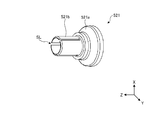
- FIG. 3 is a perspective view of the first member in the balance adjusting unit according to the embodiment.
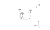
- FIG. 4 is a perspective view of a second member in the balance adjustment unit according to the embodiment.
- FIG. 5 is a diagram showing a change in state when the first member and the second member are mounted.
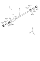
- FIG. 6 is an exploded perspective view of the rotor according to the embodiment.
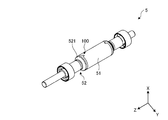
- FIG. 7 is a perspective view of the rotor according to the embodiment.
- FIG. 8 is a perspective view of a rotor according to a modification.
- FIG. 1 is a perspective view of a motor 1 according to the embodiment.
- the motor 1 includes a rotating shaft 2 and a main body 3.
- the rotation shaft 2 extends at a position passing through the central axis of the columnar main body 3 and is provided so as to protrude from the main body 3 toward the Z-axis positive direction, which is the axial direction.
- the Z-axis direction that is the extending direction of the rotation shaft 2 is referred to as the rotation axis direction.
- Each drawing shows a three-dimensional orthogonal coordinate system including the Z-axis for easy understanding.
- the main body 3 is a substantially cylindrical casing, and accommodates a stator 4 and a rotor 5 described later.
- a stator 4 and a rotor 5 described later.
- the internal configuration of the main body 3 in the motor 1 will be described with reference to FIG.
- FIG. 2 is a cross-sectional view of the motor 1 according to the embodiment.
- FIG. 2 shows a cross section of the motor 1 taken along the line AA in FIG.
- the motor 1 includes a stator 4 and a rotor 5.
- stator 4 and the rotor 5 are accommodated inside the main body 3 by the cylindrical portion 31, the first cap 32, and the second cap 33 in the main body 3.
- the stator 4 is a stator in the motor 1 and is provided with a cylindrical stator core 41 and a stator core 41 that are formed by stacking a plurality of plate-like metal members such as soft magnetic steel plates such as silicon steel plates and electromagnetic steel plates. And a coil 42 wound around the teeth.
- the rotor 5 is a rotor in the motor 1 and includes a magnet 51, a balance adjustment unit 52, and a bearing unit 53.
- the magnet 51 is a cylindrical permanent magnet, for example, and is fixed to the rotating shaft 2.
- a ferrite magnet or a neodymium magnet can be used as the magnet 51.
- the balance adjustment unit 52 is provided at both ends of the magnet 51 in the rotation axis direction, and adjusts the rotation balance of the rotor 5. Specifically, the balance adjustment unit 52 adjusts the rotation balance by cutting the outer peripheral surface in accordance with, for example, rotation imbalance measured in advance through experiments or the like.
- the balance adjustment unit 52 includes a first member 521 and a second member 522. Details of the first member 521 and the second member 522 will be described later. Further, FIG. 2 shows the case where the balance adjusting unit 52 is provided at both ends of the magnet 51, but the balance adjusting unit 52 may be provided only at one of the both ends.
- a pair of bearings 53 is provided by press-fitting the magnet 51 and the balance adjusting unit 52 at a position between which the magnet 51 and the balance adjusting unit 52 are sandwiched in the Z-axis direction, which is the rotation axis direction, and rotatably supports the rotation shaft 2. Thereby, it is possible to prevent the magnet 51 and the balance adjustment unit 52 from being displaced in the rotation axis direction.
- the bearing portion 53 can be configured by a rolling bearing such as a ball bearing, but is not limited thereto, and may be configured by a bearing having another structure such as a slide bearing or a magnetic bearing.
- the inner diameter of the balance adjusting part is made larger than the outer diameter of the rotating shaft, and an adhesive is put into a gap generated by the difference between the two diameters to fix both.
- the center axis of each of the balance adjusting unit and the rotating shaft may be shifted, and both may be fixed in an eccentric state.
- the balance adjusting unit is pressed into the rotating shaft and fixed, so that no gap is created between them. When doing so, the surface of the rotating shaft may be damaged or the rotating shaft may be deformed.
- the balance adjustment unit 52 includes two members, a first member 521 and a second member 522, and the second member 522 is press-fitted into the rotary shaft 2 via the first member 521. Specifically, the balance adjusting unit 52 is fixed to the rotating shaft 2 by the first member 521 pressing the second member 522 and the second member 522 pressing the rotating shaft 2 along with the pressing. . In other words, the balance adjusting unit 52 is fixed in a state where the opening of the first member 521 follows the outer diameter of the rotating shaft 2 (sometimes referred to as an interference fit).
- the balance adjusting unit 52 can be prevented from being fixed to the rotating shaft 2 in an eccentric state. Further, the balance adjusting unit 52 is configured such that when the second member 522 is press-fitted into the rotary shaft 2 via the first member 521, that is, when the second member 522 is press-fitted, the surface of the rotary shaft 2 is moved by the first member 521. Since it is protected, the surface of the rotating shaft 2 can be prevented from being damaged.
- the balance adjusting unit 52 can be fixed while maintaining a high concentricity without damaging the surface of the rotating shaft 2.
- FIG. 3 is a perspective view of the first member 521 in the balance adjustment unit 52 according to the embodiment.
- FIG. 4 is a perspective view of the second member 522 in the balance adjustment unit 52 according to the embodiment.
- the first member 521 includes a proximal end portion 521a and a distal end portion 521b.
- the first member 521 may be formed by integrally forming the base end portion 521a and the tip end portion 521b, or may be configured by combining separate members.
- the base end portion 521a is made of a metal material such as brass or stainless steel, and is an adjustment portion that adjusts the rotational balance of the rotor 5. Note that the adjustment site is not limited to being provided in the first member 521, and may be provided in the second member 522 described later.
- the adjustment portion of the base end portion 521a has a tapered shape that is inclined downward toward the distal end portion 521b, and the tapered portion is thick. That is, by making the adjustment portion of the base end portion 521a thick, the amount to be cut increases, so that the adjustment range of the rotation balance can be widened.
- the distal end portion 521b is a portion that is made of, for example, a resin material and is inserted into the second member 522.
- the tip portion 521b is configured by a member that can be bent in the X-axis direction, which is the radial direction of the rotating shaft 2.
- the tip portion 521 b has a plurality of slits SL arranged at predetermined intervals in the circumferential direction of the rotating shaft 2.
- the slit SL is a cutout portion cut out toward the Z-axis negative direction, which is the rotation axis direction from the distal end portion 521b toward the proximal end portion 521a.
- each slit SL is not limited to three, and may be two or four or more. Further, the width, depth, and shape of each slit SL may all be the same, or may be different from each other.
- the distal end portion 521b may have a shape that becomes thinner (also referred to as a tapered shape) as the distance from the proximal end portion 521a increases, and may have a shape that can be deformed by pressing the second member 522.
- the second member 522 is a cylindrical member.
- the second member 522 is made of a hard material such as a resin material or a metal material, for example.
- the opening diameter of the second end 522b is smaller than that of the first end 522a of the second member 522.
- the second end 522b is preferably not in contact with the rotating shaft 2, and further, the gap with the rotating shaft 2 is preferably as small as possible.
- the second member 522 is a bent portion that is bent inward in the radial direction of the rotating shaft 2.
- the second member 522 is a part in contact with the inner ring when the bearing portion 53 is a ball bearing. That is, by bending the second member 522, the area of the bearing portion 53 in contact with the inner ring can be increased, so that the bearing portion 53 with various inner ring widths can be handled. Further, the strength can be improved by bending.
- the second end 522b has a smaller opening diameter than the first end 522a.
- the diameters of both the openings may be the same.
- the second member 522 may be provided with an adjustment portion that adjusts the rotational balance of the rotor 5.
- the second member 522 can be thickened and the thickened portion can be configured as an adjustment site.
- FIG. 5 is a diagram illustrating a state change when the first member 521 and the second member 522 are mounted.
- FIG. 5 shows a case where the second member 522 is attached while the first member 521 and the magnet 51 are attached to the rotating shaft 2.
- an upper diagram shows a state before mounting
- a lower diagram shows a state after mounting.
- the first member 521 is provided in a state separated from the rotary shaft 2 in a state before the second member 522 is mounted.
- the second member 522 is inserted along the rotation shaft 2 toward the first member 521.
- the first end 522a of the second member 522 and the tip 521b of the first member 521 have a tapered shape.
- the first end portion 522 a of the second member 522 has a tapered shape that tapers toward the first member 521
- the distal end portion 521 b has a tapered shape that tapers toward the second member 522. is there. This facilitates the insertion of the distal end portion 521b into the second member 522, so that the distal end portion 521b can be prevented from being damaged during manufacturing.
- the second member 522 has a first end 522 a that is in contact with the end surface of the base end 521 a of the first member 521, and the tip 521 b of the first member 521 is connected to the rotating shaft 2. It is fixed in the state pushed toward. And the front-end
- the first member 521 has a base end portion 521 a that is one end on the side close to the magnet 51, separated from the outer peripheral surface of the rotating shaft 2, and a tip end portion 521 b that is the other end.
- the tip is in contact with the rotating shaft 2 with the second member 522 being bent by press-fitting.
- the second member 522 is press-fitted into the rotating shaft 2 via the first member 521, and as a result, the balance adjusting unit 52 is fixed to the rotating shaft 2.
- the balance adjusting portion 52 can be easily fixed to the rotary shaft 2 without using an adhesive.
- FIG. 5 shows the case where the second member 522 is inserted and fixed until the first end 522a is in contact with the base end 521a of the first member 521, but the first end 522a and the base end are shown.
- the portion 521a may be fixed in a separated state.
- the balance adjusting unit 52 is fixed in a state where the tip of the tip 521 b of the first member 521 and the second end 522 b of the second member 522 are separated from each other.
- the second end 522b may be fixed in contact with the second end 522b. In such a case, it can be said that the second end portion 522b functions as a stopper of the tip end portion 521b.
- FIG. 6 is an exploded perspective view of the rotor 5 according to the embodiment.
- FIG. 7 is a perspective view of the rotor 5 according to the embodiment.
- one of the pair of first members 521 is inserted to a predetermined position of the rotary shaft 2.
- the first member 521-2 on the Z-axis negative direction side in FIG. 6 is inserted.
- the second member 522-2 is press-fitted into the distal end portion 521b-2 of the first member 521-2.
- the balance adjusting unit 52 including the first member 521-2 and the second member 522-2 is fixed to the rotating shaft 2.
- the magnet 51 is moved from the Z-axis positive direction side to a position in contact with the end surface of the base end portion 521a-2 of the first member 521-2. insert. Thereby, the end surface 51b of the magnet 51 and the end surface of the base end portion 521a-2 are bonded and fixed, and the magnet 51 is fixed to the rotating shaft 2. Since the magnet 51 is bonded and fixed to the first member 521-2, it is difficult to shift from the central axis of the rotating shaft 2. In other words, the magnet 51 is in a rotation-stopped state by being coupled with the first member 521-2, so that it is possible to prevent a rotational shift that is a shift in the circumferential direction. Moreover, the adhesive member applied to the magnet 51 may be, for example, a double-sided tape, a liquid adhesive, a resin member, or a metal member welded.
- an adhesive member may be applied to the outer peripheral surface of the rotary shaft 2, and the adhesive member may be interposed between the rotary shaft 2 and the magnet 51 to fix them.
- the magnet 51 is a soft material such as a rubber magnet, it may be press-fitted and fixed.
- the end surface of the base end portion 521a-1 of the other first member 521-1 is inserted from the Z axis positive direction side to a position where it contacts the end surface 51a of the magnet 51.
- the end surface of the base end portion 521a-1 of the first member 521-1 and the end surface 51a of the magnet 51 are bonded and fixed.
- the second member 522-1 is press-fitted into the distal end portion 521b-1 of the first member 521-1.
- the balance adjusting unit 52 including the first member 521-1 and the second member 522-1 is fixed to the rotating shaft 2.
- a pair of bearing portions 53-1 and 53-2 are inserted from both ends so as to press-fit at a position where the magnet 51, the first members 521-1 and 521-2 and the second members 522-1 and 522-2 are sandwiched.
- the manufacture of the rotor 5 shown in FIG. 7 is completed.
- the first member 521-2 and the second member 522-2 are first inserted into the rotating shaft 2 and then the magnet 51 is inserted.
- the magnet 51 is inserted.
- the first member 521-2 and the second member 522-2 may be inserted into the rotating shaft 2.
- the adhesive member is applied to the end surfaces 51a and 51b of the magnet 51, the present invention is not limited to this.
- at least one of the end surfaces 51a and 51b of the magnet 51 and the end surface of the first member 521 is roughened.
- the magnet 51 and the first member 521 may be prevented from rotating independently of each other.
- the balance adjusting unit 52 roughens the surface so that the end surface of the first member 521 and the end surfaces 51a and 51b of the magnet 51 are fixed by the frictional resistance generated by the mutual surface roughness. Thereby, since the balance adjustment part 52 becomes attachable / detachable with respect to the magnet 51, maintainability improves.
- the rotor 5 includes the cylindrical magnet 51 and the balance adjusting unit 52.
- the balance adjustment unit 52 is provided at at least one end in the rotation axis direction of the magnet 51 and adjusts the rotation balance of the rotor 5.
- the balance adjustment unit 52 includes a first member 521 that contacts the end of the magnet 51 and a second member 522 that is press-fitted into the rotary shaft 2 via the first member 521.
- the balance adjusting unit 52 can be prevented from being fixed to the rotating shaft 2 in an eccentric state. Further, the balance adjusting unit 52 is configured such that when the second member 522 is press-fitted into the rotary shaft 2 via the first member 521, that is, when the second member 522 is press-fitted, the surface of the rotary shaft 2 is moved by the first member 521. Since it is protected, the surface of the rotating shaft 2 can be prevented from being damaged.
- the balance adjusting unit 52 and the magnet 51 are fixed by the adhesive member.
- the present invention is not limited to this.
- the balance adjusting unit 52 and the magnet 51 are fixed by an inlay structure. You can also. This point will be described with reference to FIG.
- FIG. 8 is a perspective view of the rotor 5 according to a modification. As shown in FIG. 8, in the balance adjusting unit 52, the first member 521 is fixed to the end of the magnet 51 by the spigot structure 100.
- the balance adjusting unit 52 has a protruding portion that protrudes from the first member 521 toward the magnet 51.
- the magnet 51 has a recessed portion whose end is recessed toward the opposite side to the first member 521.
- the inlay structure 100 is formed because the protrusion part of the 1st member 521 and the hollow part of the magnet 51 mesh.
- the balance adjusting unit 52 can be detachably fixed to the magnet 51 without adding a new member.
Landscapes
- Engineering & Computer Science (AREA)
- Power Engineering (AREA)
- Manufacturing & Machinery (AREA)
- Manufacture Of Motors, Generators (AREA)
- Permanent Field Magnets Of Synchronous Machinery (AREA)
Abstract
実施形態に係るロータ(5)は、筒状のマグネット(51)と、バランス調整部(52)とを備える。バランス調整部(52)は、マグネット(51)の回転軸(2)方向における少なくとも一方の端部に設けられ、ロータ(5)の回転バランスを調整する。また、バランス調整部(52)は、マグネット(51)の端部と接する第1部材(521)と、第1部材(521)を介して回転軸(2)に圧入される第2部材(522)とを有する。
Description
本発明は、ロータ、モータおよびロータの製造方法に関する。
従来、特に高速モータ等の回転電機において、回転体であるロータの回転バランスを調整するバランス調整部を備えるロータが提案されている。かかるロータでは、バランス調整部の外周面を削ったり、かかる外周面にパテを追加したりすることで回転のアンバランスを調整する。
ところで、バランス調整部と回転軸とを固定する場合、バランス調整部の内径を回転軸の外径よりも大きくして、径の違いにより生じる隙間に接着剤を入れて両者を固定することが一般的である。
しかしながら、上記した方法で固定した場合、バランス調整部と回転軸との軸ずれにより偏心した状態で両者が固定されるおそれがあった。
本発明は、上記に鑑みてなされたものであって、バランス調整部と回転軸とを偏心させずに固定することができるロータ、モータおよびロータの製造方法を提供することを目的とする。
上述した課題を解決し、目的を達成するために、本発明の一態様に係るロータは、筒状のマグネットと、バランス調整部とを備える。前記バランス調整部は、前記マグネットの回転軸方向における少なくとも一方の端部に設けられ、ロータの回転バランスを調整する。また、前記バランス調整部は、前記マグネットの前記端部と接する第1部材と、当該第1部材を介して前記回転軸に圧入される第2部材とを有する。
本発明の一態様によれば、バランス調整部と回転軸とを偏心させずに固定することができるロータ、モータおよびロータの製造方法を提供することができる。
以下、実施形態に係るロータ、モータおよびロータの製造方法について図面を参照して説明する。なお、図面における各要素の寸法の関係、各要素の比率などは、現実と異なる場合がある。図面の相互間においても、互いの寸法の関係や比率が異なる部分が含まれている場合がある。また、以下では、モータの一例としてインナーロータ型のブラシレスモータを挙げて説明する。
まず、図1を用いて実施形態に係るモータの外観について説明する。図1は、実施形態に係るモータ1の斜視図である。
図1に示すように、実施形態に係るモータ1は、回転軸2と、本体部3とを備える。回転軸2は、円柱状である本体部3の中心軸を通る位置で延在し、本体部3から軸方向であるZ軸正方向側へ突出して設けられる。なお、以下では、回転軸2の延在方向であるZ軸方向を回転軸方向と記載する。また、各図面には、説明を分かりやすくするためにかかるZ軸を含む3次元の直交座標系を図示している。
本体部3は、略円柱状の筐体であり、内部に後述のステータ4やロータ5等を収容する。ここで、図2を用いて、モータ1における本体部3の内部構成について説明する。
図2は、実施形態に係るモータ1の断面図である。図2では、図1におけるA-A線で切断した場合のモータ1の断面を示す。図2に示すように、モータ1は、ステータ4とロータ5とを備える。
また、図2に示すように、ステータ4およびロータ5は、本体部3における筒部31と、第1キャップ32と、第2キャップ33とによって本体部3の内部に収容される。
ステータ4は、モータ1における固定子であり、例えばケイ素鋼板、電磁鋼板等といった軟磁性鋼板等の板状の金属部材が複数積まれて形成される円筒状のステータコア41とステータコア41が備える図示しないティースに巻回されるコイル42とを備える。
ロータ5は、モータ1における回転子であり、マグネット51と、バランス調整部52と、軸受部53とを備える。マグネット51は、例えば、筒状の永久磁石であり、回転軸2に対して固定される。なお、マグネット51は、例えばフェライト磁石やネオジム磁石等を用いることができる。
バランス調整部52は、マグネット51の回転軸方向における両端に設けられ、ロータ5の回転バランスを調整する。具体的には、バランス調整部52は、例えば実験等により予め測定した回転のアンバランスに応じて外周面を削ることで回転バランスを調整する。
また、バランス調整部52は、第1部材521と第2部材522とを備える。なお、第1部材521および第2部材522の詳細については後述する。また、図2では、バランス調整部52は、マグネット51の両端に設けられる場合を示したが、かかる両端のうち、いずれか一方の端部にのみ設けられてもよい。
軸受部53は、マグネット51およびバランス調整部52を回転軸方向であるZ軸方向に挟み込む位置で圧入して1対設けられ、回転軸2を回転自在に支持する。これにより、マグネット51およびバランス調整部52が回転軸方向に位置ずれすることを防止できる。例えば、軸受部53は、ボールベアリング等の転がり軸受で構成できるが、これに限定されず、すべり軸受や磁気軸受等といった他の構造の軸受で構成されてもよい。
ところで、一般に、バランス調整部を回転軸に固定する場合、バランス調整部の内径を回転軸の外径よりも大きくし、両者の径の違いにより生じる隙間に接着剤を入れて両者を固定する。
しかしながら、従来のバランス調整部では、上記した接着剤による固定を行った場合、バランス調整部および回転軸それぞれの中心軸がずれることで、偏心した状態で両者が固定されるおそれがあった。
また、仮に、バランス調整部の内径を回転軸の外径より小さくした場合、バランス調整部を回転軸に圧入して固定することで、両者の間に隙間が生じなくなるが、バランス調整部を圧入する際、回転軸の表面を傷つけたり、回転軸を変形させたりするおそれがある。
そこで、実施形態に係るバランス調整部52は、第1部材521および第2部材522の2つの部材で構成され、第2部材522が第1部材521を介して回転軸2に圧入される。具体的には、バランス調整部52は、第1部材521が第2部材522を押圧し、第2部材522がかかる押圧に伴って回転軸2を押圧することで、回転軸2に固定される。換言すれば、バランス調整部52は、第1部材521の開口が回転軸2の外径に倣った状態で固定される(しまり嵌めとも呼ばれることがある)。
これにより、バランス調整部52は、回転軸2の間に隙間が生じないため、偏心した状態で回転軸2に固定されることを防止できる。また、バランス調整部52は、第2部材522が第1部材521を介して回転軸2に圧入される、すなわち、第2部材522を圧入する際、第1部材521によって回転軸2の表面が保護されるため、回転軸2の表面が傷つくことを防止できる。
このように、実施形態に係るロータ5では、回転軸2の表面を傷つけることなく、高い同心度を保った状態でバランス調整部52を固定することができる。
次に、図3および図4を用いて、実施形態に係るバランス調整部52についてさらに説明する。図3は、実施形態に係るバランス調整部52における第1部材521の斜視図である。図4は、実施形態に係るバランス調整部52における第2部材522の斜視図である。
まず、図3を用いて、第1部材521について説明する。図3に示すように、第1部材521は、基端部521aと、先端部521bとを備える。なお、第1部材521は、基端部521aと、先端部521bとが一体成形されてもよく、それぞれ別部材が組み合わされて構成されてもよい。
基端部521aは、例えば、真鍮やステンレス鋼等といった金属材料で構成され、ロータ5の回転バランスを調整する調整部位である。なお、調整部位は、第1部材521に設けられる場合に限定されず、後述の第2部材522に設けられてもよい。
具体的には、基端部521aの調整部位は、先端部521bに向かって下り傾斜となるテーパー形状となっており、かかるテーパー形状の部位が肉厚状になっている。つまり、基端部521aの調整部位を肉厚状にすることで、削る量が増えるため、回転バランスの調整幅を広くすることができる。
先端部521bは、例えば樹脂材料で構成され、第2部材522に挿入される部位である。具体的には、先端部521bは、回転軸2における径方向であるX軸方向へ撓み可能な部材で構成される。
具体的には、図3に示す例では、先端部521bは、回転軸2における周方向に所定の間隔で並んだ複数のスリットSLを有する。換言すれば、スリットSLは、先端部521bから基端部521aに向かう回転軸方向であるZ軸負方向側へ向かって切り欠かれた切欠き部である。なお、第1部材521が撓んで回転軸2に固定される状態については、図5で後述する。
また、図3に示す例では、3つのスリットSLを等間隔(120度間隔)で設ける場合を示した。これにより、先端部521bは、回転軸2の外周面に対して均等に押圧できるため、押圧が偏ることによる先端部521bの破損を低減できる。なお、スリットSLの数は、3つに限定されるものではなく、2つであってもよく、4つ以上であってもよい。また、各スリットSLの幅や深さ、形状がすべて同じであってもよく、それぞれが異なっていてもよい。
なお、図3に示す例では、先端部521bに複数のスリットSLを設けることで撓み可能に構成されたが、先端部521bが撓み可能であれば、スリットSLに限定されるものではない。
例えば、先端部521bは、基端部521aから離れるに従って肉薄(先細りテーパー状ともいう)となる形状にし、第2部材522の押圧により変形可能な形状にしてもよい。
次に、図4を用いて、第2部材522について説明する。図4に示すように、第2部材522は、筒状の部材である。第2部材522は、例えば、樹脂材料や、金属材料等の硬質材料で構成される。
また、第2部材522の第1端部522aよりも第2端部522bの方が、開口の径が小さい。また、第2端部522bは、回転軸2と接しない状態であることが好ましく、さらには、回転軸2との隙間が極力小さいことが好ましい。
また、第2部材522は、回転軸2における径方向内側に向かって屈曲した屈曲部であるとも言える。第2部材522は、軸受部53がボールベアリングである場合の内輪に接する部位である。つまり、第2部材522を屈曲させることで、軸受部53の内輪と接する面積を大きくできるため、様々な内輪幅の軸受部53に対応できる。また、屈曲させることにより強度を向上させることもできる。
なお、図4では、第1端部522aよりも第2端部522bの方が、開口の径が小さい場合を示したが、両者の開口の径が同じであってもよい。
また、上記したように、ロータ5の回転バランスを調整する調整部位が第2部材522に設けられてもよい。かかる場合、例えば、第2部材522を肉厚し、かかる肉厚部を調整部位として構成することができる。
次に、図5を用いて、第1部材521および第2部材522の装着時における状態変化について説明する。図5は、第1部材521および第2部材522の装着時における状態変化を示す図である。図5では、第1部材521およびマグネット51が回転軸2に装着された状態で、第2部材522を装着する場合を示す。図5において、上段には装着前の状態の図を示し、下段には装着後の状態の図を示す。
図5の上段に示すように、第1部材521は、第2部材522が装着される前の状態では、回転軸2から離れた状態で設けられる。そして、第2部材522は、回転軸2に沿って第1部材521側へ挿入される。
図5に示す例では、第2部材522の第1端部522aおよび第1部材521の先端部521bは、テーパー形状を有する。具体的には、第2部材522の第1端部522aは、第1部材521に向かって先細りとなるテーパー形状であり、先端部521bは、第2部材522に向かって先細りとなるテーパー形状である。これにより、先端部521bの第2部材522への挿入が容易になるため、製造時に先端部521bの破損を防止できる。
そして、図5の下段に示すように、第2部材522は、第1端部522aが第1部材521の基端部521aの端面に接するとともに、第1部材521の先端部521bを回転軸2へ向かって押した状態で固定される。そして、先端部521bは、第2部材522によって押されることで、回転軸2側へ撓んだ状態で回転軸2と接することとなる。
つまり、図5の下段に示す状態のように、第1部材521は、マグネット51に近い側の一端である基端部521aが回転軸2の外周面と離れ、他端である先端部521bの先端が第2部材522の圧入により撓んだ状態で回転軸2に接する。これにより、第2部材522は、第1部材521を介して回転軸2に圧入され、結果、バランス調整部52は、回転軸2に対して固定される。
このように、第1部材521の先端部521bを撓み可能な部材とすることで、接着剤を使用することなく、簡単にバランス調整部52を回転軸2に固定することができる。
なお、図5では、第2部材522は、第1端部522aが第1部材521の基端部521aに接するまで挿入されて固定される場合を示したが、第1端部522aと基端部521aとが離れた状態で固定されてもよい。
また、図5では、バランス調整部52は、第1部材521の先端部521bの先端と第2部材522の第2端部522bとが離れた状態で固定されたが、先端部521bの先端と第2端部522bとが接した状態で固定されてもよい。かかる場合、第2端部522bは、先端部521bのストッパとして機能するとも言える。
次に、図6および図7を用いて、実施形態に係るロータ5の製造方法について説明する。図6は、実施形態に係るロータ5の分解斜視図である。図7は、実施形態に係るロータ5の斜視図である。
実施形態に係るロータ5の製造方法では、まず、1対の第1部材521のうち、一方の第1部材521を回転軸2の所定の位置まで挿入する。例えば、まず、図6におけるZ軸負方向側の第1部材521-2を挿入することとする。
つづいて、挿入した第1部材521-2が回転軸方向にずれないように位置決めした状態で、かかる第1部材521-2の先端部521b-2に第2部材522-2を圧入する。これにより、第1部材521-2および第2部材522-2で構成されるバランス調整部52が回転軸2に固定される。
つづいて、マグネット51における2つの端面51a,51bとに接着部材を塗布した状態で、マグネット51をZ軸正方向側から第1部材521-2における基端部521a-2の端面と接する位置まで挿入する。これにより、マグネット51の端面51bと基端部521a-2の端面とが接着固定されるとともに、マグネット51が回転軸2に対して固定される。なお、マグネット51は、第1部材521-2と接着固定されるため、回転軸2の中心軸とずれにくくなる。換言すれば、マグネット51は、第1部材521-2との結合によって回転止めの状態となるため、周方向へのずれである回転ずれを防止できる。また、マグネット51に塗布される接着部材は、例えば、両面テープや、液状の接着剤、樹脂部材や金属部材を溶着したものであってよい。
なお、マグネット51を挿入する前に、回転軸2の外周面に接着部材を塗布し、回転軸2とマグネット51との間に接着部材を介在させて両者を固定してもよい。また、マグネット51がラバーマグネット等の柔らかい材料であれば、圧入固定としてもよい。
つづいて、Z軸正方向側から他方の第1部材521-1における基端部521a-1の端面がマグネット51の端面51aと接する位置まで挿入する。これにより、第1部材521-1における基端部521a-1の端面と、マグネット51の端面51aとが接着固定される。
つづいて、第1部材521-1の先端部521b-1に第2部材522-1を圧入する。これにより、第1部材521-1および第2部材522-1で構成されるバランス調整部52が回転軸2に固定される。つづいて、マグネット51、第1部材521-1,521-2および第2部材522-1,522-2を挟み込む位置で圧入するように一対の軸受部53-1,53-2を両端から挿入することで、図7に示すロータ5の製造が完了する。
そして、図7に示す完成後のロータ5の回転バランスを測定し、アンバランスが生じた場合、露出した箇所である第1部材521における基端部521aの外周面を削ることでアンバランスを解消する。
なお、上記したロータ5の製造方法では、まず、第1部材521-2および第2部材522-2を回転軸2に挿入してから、マグネット51を挿入したが、例えば、マグネット51を挿入してから、第1部材521-2および第2部材522-2を回転軸2に挿入してもよい。
また、マグネット51の端面51a,51bに接着部材を塗布したが、これに限定されるものではなく、例えば、マグネット51の端面51a,51bおよび第1部材521の端面の少なくとも一方の表面を荒くして、マグネット51と第1部材521とが互いに独立して回転することを防止してもよい。
具体的には、バランス調整部52は、第1部材521の端面とマグネット51の端面51a,51bとが互いの表面粗さにより生じる摩擦抵抗によって固定されるように、表面を荒くする。これにより、バランス調整部52がマグネット51に対して着脱可能になるため、メンテナンス性が向上する。
上述したように、実施形態に係るロータ5は、筒状のマグネット51と、バランス調整部52とを備える。バランス調整部52は、マグネット51の回転軸方向における少なくとも一方の端部に設けられ、ロータ5の回転バランスを調整する。また、バランス調整部52は、マグネット51の端部と接する第1部材521と、第1部材521を介して回転軸2に圧入される第2部材522とを有する。
これにより、バランス調整部52は、回転軸2の間に隙間が生じないため、偏心した状態で回転軸2に固定されることを防止できる。また、バランス調整部52は、第2部材522が第1部材521を介して回転軸2に圧入される、すなわち、第2部材522を圧入する際、第1部材521によって回転軸2の表面が保護されるため、回転軸2の表面が傷つくことを防止できる。
なお、上述した実施形態では、バランス調整部52とマグネット51とを接着部材で固定する場合を示したが、これに限らず、例えば、バランス調整部52とマグネット51とをインロー構造によって固定することもできる。かかる点について、図8を用いて説明する。
図8は、変形例に係るロータ5の斜視図である。図8に示すように、バランス調整部52は、第1部材521がマグネット51の端部に対してインロー構造100によって固定される。
具体的には、バランス調整部52は、第1部材521からマグネット51に向かって突出する突出部を有する。また、マグネット51は、端部が第1部材521とは反対側へ窪んだ窪み部を有する。そして、第1部材521の突出部と、マグネット51の窪み部とがかみ合うことでインロー構造100が形成される。これにより、バランス調整部52とマグネット51とが固定され、互いに独立して回転することが防止される。
このように、インロー構造100を用いることで、新たな部材を追加することなく、バランス調整部52をマグネット51に対して着脱可能に固定することができる。
また、上記実施の形態により本発明が限定されるものではない。上述した各構成素を適宜組み合わせて構成したものも本発明に含まれる。また、さらなる効果や変形例は、当業者によって容易に導き出すことができる。よって、本発明のより広範な態様は、上記の実施の形態に限定されるものではなく、様々な変更が可能である。
1 モータ、2 回転軸、3 本体部、4 ステータ、5 ロータ、31 筒部、32 第1キャップ、33 第2キャップ、41 ステータコア、42 コイル、51 マグネット、51a,51b 端面、52 バランス調整部、53,53-1,53-2 軸受部、100 インロー構造、521,521-1 第1部材、521a,521a―1,521a―2 基端部、521b,521b-1,521b-2 先端部、522,522-1,522-2 第2部材、522a 第1端部、522b 第2端部、SL スリット
Claims (12)
- 回転軸が挿入される筒状のマグネットと、
前記マグネットの回転軸方向における少なくとも一方の端部に設けられ、ロータの回転バランスを調整するバランス調整部と、を備え、
前記バランス調整部は、
前記マグネットの前記端部と接する第1部材と、
当該第1部材を介して前記回転軸に圧入されている第2部材と、を有する、
ロータ。 - 前記第1部材は、
前記マグネットに近い側の一端が前記回転軸の外周面と離れ、他端が前記第2部材への圧入により撓んだ状態で前記回転軸に接する、
請求項1に記載のロータ。 - 前記第1部材は、
前記他端側に前記回転軸方向へのスリットが形成されている、
請求項2に記載のロータ。 - 前記第1部材は、
前記回転バランスを調整可能な調整部位が設けられる、
請求項1~3のいずれか1つに記載のロータ。 - 前記マグネットおよび前記バランス調整部を前記回転軸方向に挟み込む位置で圧入した状態で設けられ、前記回転軸を回転自在に支持する1対の軸受部をさらに備える、
請求項1~4のいずれか1つに記載のロータ。 - 前記バランス調整部は、
前記第1部材が前記マグネットの前記端部に固定されている、
請求項1~5のいずれか1つに記載のロータ。 - 前記バランス調整部は、
前記第1部材が前記マグネットの前記端部に接着部材によって固定されている、
請求項6に記載のロータ。 - 前記バランス調整部は、
前記第1部材が前記マグネットの前記端部に対してインロー構造によって固定されている、
請求項6に記載のロータ。 - 前記バランス調整部は、
前記第1部材と前記マグネットの前記端部とが互いの表面粗さにより生じる摩擦抵抗によって固定されている、
請求項6に記載のロータ。 - 請求項1~9のいずれか1つに記載のロータと、
ステータと、
を備えるモータ。 - 筒状のマグネットを回転軸に挿入するマグネット挿入工程と、
前記マグネットの回転軸方向における少なくとも一方の端部に、ロータの回転バランスを調整するバランス調整部を前記回転軸に挿入するバランス調整部挿入工程と、を含み、
前記バランス調整部挿入工程は、
前記マグネットの前記端部と接するまで第1部材を前記回転軸に挿入する第1工程と、
第2部材を前記回転軸に挿入して、当該第2部材を、前記第1部材を介して前記回転軸に圧入する第2工程と、
を含むロータの製造方法。 - 回転軸が挿入される筒状のマグネットと、
前記マグネットの回転軸方向における少なくとも一方の端部に設けられ、ロータの回転バランスを調整するバランス調整部と、を備え、
前記バランス調整部は、
前記マグネットの前記端部と接する第1部材と、
当該第1部材を介して前記回転軸に圧入されている第2部材と、を有するロータの製造方法であって、
前記第1部材を前記回転軸に挿入する第1工程と、
前記第1工程後、前記第2部材を前記回転軸に挿入して、当該第2部材を、前記第1部材を介して前記回転軸に圧入する第2工程と、
前記第2工程後、前記マグネットを、当該マグネットの端部が前記第1部材に接するまで前記回転軸に挿入するマグネット挿入工程と、
を含むロータの製造方法。
Priority Applications (4)
| Application Number | Priority Date | Filing Date | Title |
|---|---|---|---|
| CN201880088044.0A CN111684685B (zh) | 2018-01-31 | 2018-08-27 | 转子、马达以及转子的制造方法 |
| US16/961,815 US11277053B2 (en) | 2018-01-31 | 2018-08-27 | Rotor, motor, and method for manufacturing rotor |
| DE112018006984.2T DE112018006984T5 (de) | 2018-01-31 | 2018-08-27 | Rotor, motor, und verfahren zur herstellung eines rotors |
| US17/654,672 US11757327B2 (en) | 2018-01-31 | 2022-03-14 | Rotor, motor, and method for manufacturing rotor |
Applications Claiming Priority (2)
| Application Number | Priority Date | Filing Date | Title |
|---|---|---|---|
| JP2018014642A JP6935342B2 (ja) | 2018-01-31 | 2018-01-31 | ロータ、モータおよびロータの製造方法 |
| JP2018-014642 | 2018-01-31 |
Related Child Applications (2)
| Application Number | Title | Priority Date | Filing Date |
|---|---|---|---|
| US16/961,815 A-371-Of-International US11277053B2 (en) | 2018-01-31 | 2018-08-27 | Rotor, motor, and method for manufacturing rotor |
| US17/654,672 Continuation-In-Part US11757327B2 (en) | 2018-01-31 | 2022-03-14 | Rotor, motor, and method for manufacturing rotor |
Publications (1)
| Publication Number | Publication Date |
|---|---|
| WO2019150629A1 true WO2019150629A1 (ja) | 2019-08-08 |
Family
ID=67479667
Family Applications (1)
| Application Number | Title | Priority Date | Filing Date |
|---|---|---|---|
| PCT/JP2018/031596 Ceased WO2019150629A1 (ja) | 2018-01-31 | 2018-08-27 | ロータ、モータおよびロータの製造方法 |
Country Status (5)
| Country | Link |
|---|---|
| US (1) | US11277053B2 (ja) |
| JP (1) | JP6935342B2 (ja) |
| CN (1) | CN111684685B (ja) |
| DE (1) | DE112018006984T5 (ja) |
| WO (1) | WO2019150629A1 (ja) |
Families Citing this family (4)
| Publication number | Priority date | Publication date | Assignee | Title |
|---|---|---|---|---|
| US11757327B2 (en) * | 2018-01-31 | 2023-09-12 | Minebea Mitsumi Inc. | Rotor, motor, and method for manufacturing rotor |
| DE102022207609A1 (de) | 2022-07-26 | 2024-02-01 | Mahle International Gmbh | Gebaute Rotorwelle eines Elektromotors und Elektromotor |
| JPWO2024048184A1 (ja) * | 2022-08-29 | 2024-03-07 | ||
| GB2626582B (en) * | 2023-01-27 | 2025-09-10 | Dyson Technology Ltd | A Rotor Assembly |
Citations (3)
| Publication number | Priority date | Publication date | Assignee | Title |
|---|---|---|---|---|
| JP2006304565A (ja) * | 2005-04-25 | 2006-11-02 | Matsushita Electric Ind Co Ltd | ブラシレスモータとその製造方法 |
| US20120062050A1 (en) * | 2010-09-13 | 2012-03-15 | Alex Horng | Rotor for Motor |
| JP2015070786A (ja) * | 2013-09-26 | 2015-04-13 | エスカエフ・マニュティック・メシャトロニク | 永久磁石回転子軸組立体および方法 |
Family Cites Families (19)
| Publication number | Priority date | Publication date | Assignee | Title |
|---|---|---|---|---|
| DE3808311A1 (de) * | 1988-03-12 | 1989-09-21 | Frankl & Kirchner | Rotor fuer eine permanent-magnetisch erregte elektrische maschine |
| JP3411617B2 (ja) * | 1993-03-25 | 2003-06-03 | 神鋼電機株式会社 | 回転電機における永久磁石型回転子 |
| JP2005176530A (ja) * | 2003-12-12 | 2005-06-30 | Meidensha Corp | 永久磁石形回転電機の回転バランス修正構造 |
| JP2007135332A (ja) | 2005-11-11 | 2007-05-31 | Osada Res Inst Ltd | ブラシレスモータ及び該ブラシレスモータに用いるロータ |
| KR20080023456A (ko) * | 2006-09-11 | 2008-03-14 | 삼성광주전자 주식회사 | 압축기 모터의 마그네트 착자방법 |
| JP2011083136A (ja) * | 2009-10-08 | 2011-04-21 | Panasonic Corp | ロータ、モータ、発電機、電動送風機ならびに電気掃除機 |
| DE102011110752A1 (de) * | 2010-08-20 | 2012-03-15 | Johnson Electric S.A. | Bürstenloser Motor |
| JP2012165534A (ja) * | 2011-02-04 | 2012-08-30 | Fuji Electric Co Ltd | 永久磁石形回転電機のロータ及びそのバランス調整方法 |
| JP5615231B2 (ja) * | 2011-06-08 | 2014-10-29 | 三菱電機株式会社 | 電動機内蔵過給装置のバランス調整構造とその方法 |
| US9246365B2 (en) * | 2012-01-23 | 2016-01-26 | Aisan Kogyo Kabushiki Kaisha | Regulation of permanent magnet motion in a brushless motor |
| JP5973839B2 (ja) * | 2012-08-21 | 2016-08-23 | 株式会社荏原製作所 | 真空ポンプ用モータ及びこれを備える真空ポンプ |
| KR101367054B1 (ko) * | 2012-08-28 | 2014-02-24 | 삼성전기주식회사 | 스위치드 릴럭턴스 모터 어셈블리 |
| JP6055725B2 (ja) * | 2013-06-28 | 2016-12-27 | 株式会社日立産機システム | 回転子および回転子を用いたアキシャル型回転電機 |
| JP6327907B2 (ja) * | 2014-03-28 | 2018-05-23 | アイチエレック株式会社 | 永久磁石電動機および圧縮機 |
| EP3176929B1 (en) * | 2014-07-31 | 2021-05-19 | Nakanishi Inc. | Electric motor and dental device |
| CN104348279B (zh) * | 2014-10-22 | 2017-12-08 | 广东威灵电机制造有限公司 | 转子及具有其的电机 |
| JP2016092966A (ja) * | 2014-11-05 | 2016-05-23 | 日本電産テクノモータ株式会社 | ロータおよびモータ |
| CN205544760U (zh) * | 2016-03-20 | 2016-08-31 | 东莞市精一机器人科技有限公司 | 一种微型振动马达 |
| JP6412895B2 (ja) * | 2016-05-06 | 2018-10-24 | 本田技研工業株式会社 | 回転電機のロータのバランス修正方法 |
-
2018
- 2018-01-31 JP JP2018014642A patent/JP6935342B2/ja active Active
- 2018-08-27 US US16/961,815 patent/US11277053B2/en active Active
- 2018-08-27 DE DE112018006984.2T patent/DE112018006984T5/de active Pending
- 2018-08-27 CN CN201880088044.0A patent/CN111684685B/zh active Active
- 2018-08-27 WO PCT/JP2018/031596 patent/WO2019150629A1/ja not_active Ceased
Patent Citations (3)
| Publication number | Priority date | Publication date | Assignee | Title |
|---|---|---|---|---|
| JP2006304565A (ja) * | 2005-04-25 | 2006-11-02 | Matsushita Electric Ind Co Ltd | ブラシレスモータとその製造方法 |
| US20120062050A1 (en) * | 2010-09-13 | 2012-03-15 | Alex Horng | Rotor for Motor |
| JP2015070786A (ja) * | 2013-09-26 | 2015-04-13 | エスカエフ・マニュティック・メシャトロニク | 永久磁石回転子軸組立体および方法 |
Also Published As
| Publication number | Publication date |
|---|---|
| JP2019134585A (ja) | 2019-08-08 |
| US20210075294A1 (en) | 2021-03-11 |
| DE112018006984T5 (de) | 2020-10-08 |
| JP6935342B2 (ja) | 2021-09-15 |
| CN111684685A (zh) | 2020-09-18 |
| US11277053B2 (en) | 2022-03-15 |
| CN111684685B (zh) | 2022-09-27 |
Similar Documents
| Publication | Publication Date | Title |
|---|---|---|
| WO2019150629A1 (ja) | ロータ、モータおよびロータの製造方法 | |
| JP2016093021A (ja) | ロータ構造 | |
| WO2015162956A1 (ja) | ロータ、ロータの製造方法及びロータを備える回転電機 | |
| JP5391325B1 (ja) | 電動機にコイルを固定するコイル固定装置、及び該コイル固定装置を備えた電動機 | |
| US10742081B2 (en) | Rotor and motor | |
| US20020047390A1 (en) | Motor | |
| JP2019205340A (ja) | 電気モータ及びそのロータ | |
| JP6967987B2 (ja) | ロータ、モータおよびロータの製造方法 | |
| JP6074887B2 (ja) | 電動機の組み立てに用いられるギャップゲージおよび電動機の製造方法 | |
| JP6981959B2 (ja) | 電気モータのための磁気ホィール | |
| WO2019123952A1 (ja) | ロータおよびモータ | |
| JP6975129B2 (ja) | 回転電機のロータ | |
| KR101867973B1 (ko) | 모터의 로터 및 이를 갖는 모터 | |
| EP3193142A2 (en) | Fixing structure of resolver rotor and fixing structure of rotation body for motor | |
| US11757327B2 (en) | Rotor, motor, and method for manufacturing rotor | |
| JP2018201302A (ja) | モータ | |
| JP2018157705A (ja) | ロータおよびレゾルバ | |
| JP6585690B2 (ja) | ホルダ、電動機および温度検出素子の固定方法 | |
| WO2022107714A1 (ja) | モータ | |
| JPH0578158U (ja) | 回転電機の回転子 | |
| JP6791909B2 (ja) | 磁石が接着剤にて固定された磁石埋込み型電動機のロータおよび磁石埋込み型電動機のロータの製造方法 | |
| JP7672427B2 (ja) | モータの製造方法 | |
| JP2016086620A (ja) | 回転電機の回転子 | |
| JP5422879B2 (ja) | エアギャップ測定方法及びアキシャルギャップ型回転機の製造方法及びアキシャルギャップ型回転機 | |
| WO2026006973A1 (zh) | 步进电机 |
Legal Events
| Date | Code | Title | Description |
|---|---|---|---|
| 121 | Ep: the epo has been informed by wipo that ep was designated in this application |
Ref document number: 18903191 Country of ref document: EP Kind code of ref document: A1 |
|
| 122 | Ep: pct application non-entry in european phase |
Ref document number: 18903191 Country of ref document: EP Kind code of ref document: A1 |