WO2019146513A1 - 流体漏れ検出機器及び往復動型流体圧機器 - Google Patents
流体漏れ検出機器及び往復動型流体圧機器 Download PDFInfo
- Publication number
- WO2019146513A1 WO2019146513A1 PCT/JP2019/001402 JP2019001402W WO2019146513A1 WO 2019146513 A1 WO2019146513 A1 WO 2019146513A1 JP 2019001402 W JP2019001402 W JP 2019001402W WO 2019146513 A1 WO2019146513 A1 WO 2019146513A1
- Authority
- WO
- WIPO (PCT)
- Prior art keywords
- cylinder head
- piston rod
- fluid
- annular member
- press
- Prior art date
- Legal status (The legal status is an assumption and is not a legal conclusion. Google has not performed a legal analysis and makes no representation as to the accuracy of the status listed.)
- Ceased
Links
Images
Classifications
-
- F—MECHANICAL ENGINEERING; LIGHTING; HEATING; WEAPONS; BLASTING
- F15—FLUID-PRESSURE ACTUATORS; HYDRAULICS OR PNEUMATICS IN GENERAL
- F15B—SYSTEMS ACTING BY MEANS OF FLUIDS IN GENERAL; FLUID-PRESSURE ACTUATORS, e.g. SERVOMOTORS; DETAILS OF FLUID-PRESSURE SYSTEMS, NOT OTHERWISE PROVIDED FOR
- F15B15/00—Fluid-actuated devices for displacing a member from one position to another; Gearing associated therewith
- F15B15/08—Characterised by the construction of the motor unit
- F15B15/14—Characterised by the construction of the motor unit of the straight-cylinder type
- F15B15/1423—Component parts; Constructional details
- F15B15/1428—Cylinders
-
- F—MECHANICAL ENGINEERING; LIGHTING; HEATING; WEAPONS; BLASTING
- F15—FLUID-PRESSURE ACTUATORS; HYDRAULICS OR PNEUMATICS IN GENERAL
- F15B—SYSTEMS ACTING BY MEANS OF FLUIDS IN GENERAL; FLUID-PRESSURE ACTUATORS, e.g. SERVOMOTORS; DETAILS OF FLUID-PRESSURE SYSTEMS, NOT OTHERWISE PROVIDED FOR
- F15B15/00—Fluid-actuated devices for displacing a member from one position to another; Gearing associated therewith
- F15B15/08—Characterised by the construction of the motor unit
- F15B15/14—Characterised by the construction of the motor unit of the straight-cylinder type
- F15B15/1423—Component parts; Constructional details
- F15B15/1433—End caps
-
- F—MECHANICAL ENGINEERING; LIGHTING; HEATING; WEAPONS; BLASTING
- F15—FLUID-PRESSURE ACTUATORS; HYDRAULICS OR PNEUMATICS IN GENERAL
- F15B—SYSTEMS ACTING BY MEANS OF FLUIDS IN GENERAL; FLUID-PRESSURE ACTUATORS, e.g. SERVOMOTORS; DETAILS OF FLUID-PRESSURE SYSTEMS, NOT OTHERWISE PROVIDED FOR
- F15B15/00—Fluid-actuated devices for displacing a member from one position to another; Gearing associated therewith
- F15B15/08—Characterised by the construction of the motor unit
- F15B15/14—Characterised by the construction of the motor unit of the straight-cylinder type
- F15B15/1423—Component parts; Constructional details
- F15B15/1457—Piston rods
- F15B15/1461—Piston rod sealings
-
- F—MECHANICAL ENGINEERING; LIGHTING; HEATING; WEAPONS; BLASTING
- F15—FLUID-PRESSURE ACTUATORS; HYDRAULICS OR PNEUMATICS IN GENERAL
- F15B—SYSTEMS ACTING BY MEANS OF FLUIDS IN GENERAL; FLUID-PRESSURE ACTUATORS, e.g. SERVOMOTORS; DETAILS OF FLUID-PRESSURE SYSTEMS, NOT OTHERWISE PROVIDED FOR
- F15B15/00—Fluid-actuated devices for displacing a member from one position to another; Gearing associated therewith
- F15B15/20—Other details, e.g. assembly with regulating devices
-
- F—MECHANICAL ENGINEERING; LIGHTING; HEATING; WEAPONS; BLASTING
- F15—FLUID-PRESSURE ACTUATORS; HYDRAULICS OR PNEUMATICS IN GENERAL
- F15B—SYSTEMS ACTING BY MEANS OF FLUIDS IN GENERAL; FLUID-PRESSURE ACTUATORS, e.g. SERVOMOTORS; DETAILS OF FLUID-PRESSURE SYSTEMS, NOT OTHERWISE PROVIDED FOR
- F15B19/00—Testing; Calibrating; Fault detection or monitoring; Simulation or modelling of fluid-pressure systems or apparatus not otherwise provided for
- F15B19/005—Fault detection or monitoring
-
- F—MECHANICAL ENGINEERING; LIGHTING; HEATING; WEAPONS; BLASTING
- F15—FLUID-PRESSURE ACTUATORS; HYDRAULICS OR PNEUMATICS IN GENERAL
- F15B—SYSTEMS ACTING BY MEANS OF FLUIDS IN GENERAL; FLUID-PRESSURE ACTUATORS, e.g. SERVOMOTORS; DETAILS OF FLUID-PRESSURE SYSTEMS, NOT OTHERWISE PROVIDED FOR
- F15B20/00—Safety arrangements for fluid actuator systems; Applications of safety devices in fluid actuator systems; Emergency measures for fluid actuator systems
- F15B20/005—Leakage; Spillage; Hose burst
-
- F—MECHANICAL ENGINEERING; LIGHTING; HEATING; WEAPONS; BLASTING
- F16—ENGINEERING ELEMENTS AND UNITS; GENERAL MEASURES FOR PRODUCING AND MAINTAINING EFFECTIVE FUNCTIONING OF MACHINES OR INSTALLATIONS; THERMAL INSULATION IN GENERAL
- F16J—PISTONS; CYLINDERS; SEALINGS
- F16J15/00—Sealings
- F16J15/002—Sealings comprising at least two sealings in succession
- F16J15/004—Sealings comprising at least two sealings in succession forming of recuperation chamber for the leaking fluid
-
- F—MECHANICAL ENGINEERING; LIGHTING; HEATING; WEAPONS; BLASTING
- F16—ENGINEERING ELEMENTS AND UNITS; GENERAL MEASURES FOR PRODUCING AND MAINTAINING EFFECTIVE FUNCTIONING OF MACHINES OR INSTALLATIONS; THERMAL INSULATION IN GENERAL
- F16J—PISTONS; CYLINDERS; SEALINGS
- F16J15/00—Sealings
- F16J15/16—Sealings between relatively-moving surfaces
- F16J15/32—Sealings between relatively-moving surfaces with elastic sealings, e.g. O-rings
- F16J15/3204—Sealings between relatively-moving surfaces with elastic sealings, e.g. O-rings with at least one lip
- F16J15/3232—Sealings between relatively-moving surfaces with elastic sealings, e.g. O-rings with at least one lip having two or more lips
- F16J15/3236—Sealings between relatively-moving surfaces with elastic sealings, e.g. O-rings with at least one lip having two or more lips with at least one lip for each surface, e.g. U-cup packings
-
- F—MECHANICAL ENGINEERING; LIGHTING; HEATING; WEAPONS; BLASTING
- F16—ENGINEERING ELEMENTS AND UNITS; GENERAL MEASURES FOR PRODUCING AND MAINTAINING EFFECTIVE FUNCTIONING OF MACHINES OR INSTALLATIONS; THERMAL INSULATION IN GENERAL
- F16J—PISTONS; CYLINDERS; SEALINGS
- F16J15/00—Sealings
- F16J15/16—Sealings between relatively-moving surfaces
- F16J15/32—Sealings between relatively-moving surfaces with elastic sealings, e.g. O-rings
- F16J15/3296—Arrangements for monitoring the condition or operation of elastic sealings; Arrangements for control of elastic sealings, e.g. of their geometry or stiffness
-
- F—MECHANICAL ENGINEERING; LIGHTING; HEATING; WEAPONS; BLASTING
- F16—ENGINEERING ELEMENTS AND UNITS; GENERAL MEASURES FOR PRODUCING AND MAINTAINING EFFECTIVE FUNCTIONING OF MACHINES OR INSTALLATIONS; THERMAL INSULATION IN GENERAL
- F16J—PISTONS; CYLINDERS; SEALINGS
- F16J15/00—Sealings
- F16J15/56—Other sealings for reciprocating rods
-
- F—MECHANICAL ENGINEERING; LIGHTING; HEATING; WEAPONS; BLASTING
- F15—FLUID-PRESSURE ACTUATORS; HYDRAULICS OR PNEUMATICS IN GENERAL
- F15B—SYSTEMS ACTING BY MEANS OF FLUIDS IN GENERAL; FLUID-PRESSURE ACTUATORS, e.g. SERVOMOTORS; DETAILS OF FLUID-PRESSURE SYSTEMS, NOT OTHERWISE PROVIDED FOR
- F15B2211/00—Circuits for servomotor systems
- F15B2211/50—Pressure control
- F15B2211/505—Pressure control characterised by the type of pressure control means
- F15B2211/50509—Pressure control characterised by the type of pressure control means the pressure control means controlling a pressure upstream of the pressure control means
- F15B2211/50518—Pressure control characterised by the type of pressure control means the pressure control means controlling a pressure upstream of the pressure control means using pressure relief valves
-
- F—MECHANICAL ENGINEERING; LIGHTING; HEATING; WEAPONS; BLASTING
- F15—FLUID-PRESSURE ACTUATORS; HYDRAULICS OR PNEUMATICS IN GENERAL
- F15B—SYSTEMS ACTING BY MEANS OF FLUIDS IN GENERAL; FLUID-PRESSURE ACTUATORS, e.g. SERVOMOTORS; DETAILS OF FLUID-PRESSURE SYSTEMS, NOT OTHERWISE PROVIDED FOR
- F15B2211/00—Circuits for servomotor systems
- F15B2211/60—Circuit components or control therefor
- F15B2211/63—Electronic controllers
- F15B2211/6303—Electronic controllers using input signals
- F15B2211/6306—Electronic controllers using input signals representing a pressure
-
- F—MECHANICAL ENGINEERING; LIGHTING; HEATING; WEAPONS; BLASTING
- F15—FLUID-PRESSURE ACTUATORS; HYDRAULICS OR PNEUMATICS IN GENERAL
- F15B—SYSTEMS ACTING BY MEANS OF FLUIDS IN GENERAL; FLUID-PRESSURE ACTUATORS, e.g. SERVOMOTORS; DETAILS OF FLUID-PRESSURE SYSTEMS, NOT OTHERWISE PROVIDED FOR
- F15B2211/00—Circuits for servomotor systems
- F15B2211/80—Other types of control related to particular problems or conditions
- F15B2211/86—Control during or prevention of abnormal conditions
- F15B2211/863—Control during or prevention of abnormal conditions the abnormal condition being a hydraulic or pneumatic failure
- F15B2211/864—Failure of an output member, e.g. actuator or motor failure
-
- F—MECHANICAL ENGINEERING; LIGHTING; HEATING; WEAPONS; BLASTING
- F15—FLUID-PRESSURE ACTUATORS; HYDRAULICS OR PNEUMATICS IN GENERAL
- F15B—SYSTEMS ACTING BY MEANS OF FLUIDS IN GENERAL; FLUID-PRESSURE ACTUATORS, e.g. SERVOMOTORS; DETAILS OF FLUID-PRESSURE SYSTEMS, NOT OTHERWISE PROVIDED FOR
- F15B2211/00—Circuits for servomotor systems
- F15B2211/80—Other types of control related to particular problems or conditions
- F15B2211/865—Prevention of failures
-
- F—MECHANICAL ENGINEERING; LIGHTING; HEATING; WEAPONS; BLASTING
- F15—FLUID-PRESSURE ACTUATORS; HYDRAULICS OR PNEUMATICS IN GENERAL
- F15B—SYSTEMS ACTING BY MEANS OF FLUIDS IN GENERAL; FLUID-PRESSURE ACTUATORS, e.g. SERVOMOTORS; DETAILS OF FLUID-PRESSURE SYSTEMS, NOT OTHERWISE PROVIDED FOR
- F15B2211/00—Circuits for servomotor systems
- F15B2211/80—Other types of control related to particular problems or conditions
- F15B2211/87—Detection of failures
Definitions
- the present invention relates to a fluid leak detection device and a reciprocating fluid pressure device.
- a reciprocating fluid pressure device such as a fluid pressure cylinder or a shock absorber
- the working fluid may leak from between the cylinder head and the piston rod due to deterioration of the seal member provided on the inner periphery of the cylinder head. If the amount of leakage of the working fluid is increased, the reciprocating fluid pressure device may not be able to achieve its intended performance. For these reasons, it has been proposed that a fluid leak detection device be attached to a cylinder head to detect a leak of working fluid (JPS 62-240275A).
- the fluid leak detection device disclosed in JPS62-240275A is attached to the cylinder head using a bolt. Therefore, in order to attach the fluid leak detection device to the cylinder head of the reciprocating fluid pressure device, it is necessary to form a hole for fixing the bolt in the cylinder head, and the fluid leak detection device can be easily attached. Can not.
- the present invention aims to facilitate the installation of a fluid leak detection device on a cylinder head.
- the fluid leak detector is attached to the cylinder head and formed into an annular member through which the piston rod passes, and an annular member, from between the outer periphery of the piston rod and the inner periphery of the cylinder head
- the annular member has a press-in portion press-fit into an annular groove formed in the cylinder head.
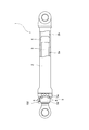
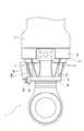
- FIG. 1 is a partial sectional view of a hydraulic cylinder according to an embodiment of the present invention.
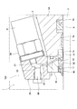
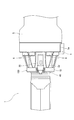
- FIG. 2 is an enlarged cross-sectional view of the hydraulic cylinder shown in FIG. 1 showing a fluid leak detector.
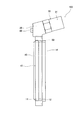
- FIG. 3 is a front view of a fluid leak detection device according to an embodiment of the present invention.
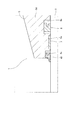
- FIG. 4 is an enlarged cross-sectional view of a hydraulic cylinder used with no fluid leak detection device attached, corresponding to FIG.
- FIG. 5 is an enlarged view showing the periphery of the cylinder head.
- FIG. 6 is an enlarged view showing the periphery of the cylinder head, and shows a state rotated 90 degrees around the axis from the state shown in FIG.
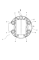
- FIG. 7 is an axial view of the hydraulic cylinder shown in FIG.
- the hydraulic cylinder 1 includes a cylindrical cylinder tube 2, a piston rod 3 inserted into the cylinder tube 2, and a piston 4 provided at one end of the piston rod 3.
- the piston 4 is slidable along the inner peripheral surface of the cylinder tube 2, and the inside of the cylinder tube 2 is divided by the piston 4 into a rod side chamber 2 a and an opposite rod side chamber 2 b.
- the piston rod 3 extends from the open end of the cylinder tube 2.
- hydraulic fluid is selectively introduced from the hydraulic pressure source (not shown) to the rod side chamber 2 a or the opposite rod side chamber 2 b, the piston rod 3 moves relative to the cylinder tube 2.
- the hydraulic cylinder 1 is operated to expand and contract.
- a cylinder head 5 At the open end of the cylinder tube 2 is provided a cylinder head 5 through which the piston rod 3 is inserted.
- the cylinder head 5 is fastened to the open end of the cylinder tube 2 using a plurality of bolts 6 as fastening members.
- annular grooves 5 a and 5 b are formed on the inner periphery of the cylinder head 5.
- a bush 7 as a bearing for slidably supporting the piston rod 3 is disposed.
- a U-packing 8 as a sealing member is disposed in the annular groove 5b.
- the U-packing 8 is compressed between the outer periphery of the piston rod 3 and the inner periphery of the cylinder head 5 to seal between them. Thereby, the hydraulic oil in the rod side chamber 2a (see FIG. 1) can be prevented from leaking to the outside.
- the bush 7 and the U-packing 8 are provided on the inner periphery of the cylinder head 5 in this order in the direction in which the hydraulic cylinder 1 contracts, but may be provided in the reverse order.
- the U-packing 8 is worn by the expansion / contraction operation of the hydraulic cylinder 1, that is, the reciprocation of the piston rod 3, and the sealability gradually decreases.
- the sealing performance decreases, the amount of hydraulic fluid leaking from the rod side chamber 2a between the outer periphery of the piston rod 3 and the inner periphery of the cylinder head 5 increases.
- the hydraulic cylinder 1 may not be able to exhibit the desired performance.
- the hydraulic cylinder 1 is provided with a fluid leak detection device 100 in order to grasp the deterioration in performance caused by the hydraulic fluid leak.
- the fluid leak detection device 100 includes an annular member 10 attached to the tip of the cylinder head 5 through which the piston rod 3 is inserted, a sensor holder 20 provided on the outer periphery of the annular member 10, and a sensor And a pressure sensor 30 as a detector held by the holder 20.
- the sensor holder 20 is fastened to the annular member 10 using a bolt not shown.
- the pressure sensor 30 is screwed and fixed to a hole 21 formed in the sensor holder 20.
- Annular grooves 11 and 12 are formed on the inner periphery of the annular member 10.
- a dust seal 40 which prevents dust from entering the cylinder tube 2 from the outside, is press-fit into the annular groove 11, and a U-packing 50 as a seal member is disposed in the annular groove 12.
- the dust seal 40 and the U-packing 50 are provided in this order in the direction in which the hydraulic cylinder 1 contracts.
- the U-packing 50 is compressed between the outer periphery of the piston rod 3 and the inner periphery of the annular member 10 to seal between them.
- the hydraulic oil introduced from the rod side chamber 2a (see FIG. 1) to the annular groove 12 through the gap between the outer periphery of the piston rod 3 and the inner periphery of the cylinder head 5 is prevented from leaking into the annular groove 11. it can.
- the annular member 10 is formed with a passage 13 passing between the bottom of the annular groove 12 and the outer periphery of the annular member 10.
- the U-packing 50 is disposed in the annular groove 12 so as not to close the opening of the passage 13, and the hydraulic oil guided to the annular groove 12 flows into the passage 13.
- the sensor holder 20 is formed with a passage 22 communicating the passage 13 of the annular member 10 and the hole 21 of the sensor holder 20. Therefore, the hydraulic oil that has flowed into the passage 13 is guided to the hole 21 of the sensor holder 20 through the passage 22.
- the pressure sensor 30 is attached to the sensor holder 20 so as to detect the pressure of the hydraulic fluid introduced to the hole 21 of the sensor holder 20.
- the pressure in the bore 21 increases with the increase of the amount of hydraulic fluid introduced into the bore 21.
- the amount of hydraulic fluid introduced into the hole 21 increases with the increase of the amount of hydraulic fluid leaking from the rod side chamber 2a (see FIG. 1) between the outer periphery of the piston rod 3 and the inner periphery of the cylinder head 5. Therefore, by measuring the pressure in the hole 21 using the pressure sensor 30, it is possible to grasp the leakage amount of the hydraulic oil.
- the pressure sensor 30 transmits a signal corresponding to the detected pressure by a transmitter 31 to a processing unit (not shown) in a wired or wireless manner.
- the processing unit determines the deterioration state of the U-packing 8 based on the detected pressure. If the detected pressure is equal to or less than a preset threshold value, the processing unit determines that the U-packing 8 replacement time has not been reached. When the detected pressure exceeds a preset threshold value, the processing unit determines that the U-packing 8 replacement time has been reached, and the U-packing 8 replacement time has been reached by a not-shown warning lamp or the like. Notify the operator.
- deterioration of the U-packing 8 can be known based on the pressure detected by the pressure sensor 30 of the fluid leak detection device 100. Therefore, the replacement time of the U-packing 8 can be easily managed.
- the annular member 10 has a press-fit portion 14 which is press-fit into an annular groove 5 c formed in the cylinder head 5.
- the outer diameter of the press-fit portion 14 is slightly larger than the inner diameter of the annular groove 5 c in a state before being press-fitted into the annular groove 5 c. Therefore, the press-fit portion 14 is tightened by the annular groove 5 c in a state of being press-fitted into the annular groove 5 c. Thereby, the press-fit portion 14 is fixed in the annular groove 5 c, and the annular member 10 is attached to the cylinder head 5.
- the annular member 10 can be attached to the cylinder head 5 by press-fitting the press-fit portion 14 into the annular groove 5c. Therefore, the fluid leak detection device 100 can be attached to the cylinder head 5 without forming a hole for fixing a fastening member such as a bolt in the cylinder head 5.
- the annular member 10 is attached to the cylinder head 5 by press-fitting the press-fit portion 14 into the annular groove 5 c, the position of the pressure sensor 30 in the circumferential direction can be easily adjusted when attaching the annular member 10 to the cylinder head 5 can do.
- the cylinder head 5 has a holding portion 5 d for holding the bush 7 and the U-packing 8, and a flange portion 5 e projecting radially from the holding portion 5 d.
- a plurality of holes (not shown) penetrating in the axial direction are formed in the flange portion 5e.
- the bolt 6 is inserted through the hole of the flange 5 e to press the flange 5 e against the open end of the cylinder tube 2.
- the bolts 6 are arranged side by side in the circumferential direction, and axially project from the flange portion 5 e of the cylinder head 5.
- the fluid leak detection device 100 is attached to the tip of the cylinder head 5 such that the pressure sensor 30 is disposed between the bolts 6 adjacent in the circumferential direction. Therefore, interference between the pressure sensor 30 and the bolt 6 can be prevented. Therefore, the pressure sensor 30 can be disposed in the vicinity of the flange portion 5e of the cylinder head 5, and the hydraulic cylinder 1 can be miniaturized.
- the pressure sensor 30 may be disposed between the bolts 6, and the fluid leak detection device 100 may be mounted on the cylinder head 5 by a method other than press fitting. It may be attached.
- the outer diameter of the press-in portion 14 is substantially equal to the outer diameter of the dust seal 40. Therefore, as shown in FIG. 4, the dust seal 40 removed from the annular groove 11 of the annular member 10 can be press-fit into the annular groove 5 c of the cylinder head 5 instead of the press-fit portion 14 of the annular member 10. Therefore, the hydraulic cylinder 1 can be used with the fluid leak detection device 100 removed from the cylinder head 5 and the dust seal 40 attached to the cylinder head 5.
- the fluid leak detection device 100 can be easily attached and used, and the fluid leak detection device 100 can be easily detached and used.
- the fluid leak detection device 100 when the hydraulic cylinder 1 is used in a state where the fluid leak detection device 100 is not attached, the fluid leak detection device 100 is used when it is necessary to manage the amount of hydraulic fluid leak due to a change in the use environment. To easily manage the amount of hydraulic fluid leakage. The same applies to the reverse.
- the sensor holder 20 is also provided with a relief valve 60 connected to the passage 13 of the annular member 10 in parallel with the pressure sensor 30.
- the sensor holder 20 is formed with a branch passage 23 branched from the passage 22, and the branch passage 23 is provided with a relief valve 60.
- the relief valve 60 opens when the pressure of the hydraulic oil in the branch passage 23 reaches a predetermined pressure, and discharges the hydraulic oil from the passage 22 through the branch passage 23 to the outside.
- the pressure in the passage 22 is limited by the relief valve 60 to a predetermined pressure.
- this predetermined pressure is also referred to as "opening pressure".
- the valve opening pressure of the relief valve 60 is set smaller than the pressure of the hydraulic fluid when the press-fit portion 14 of the annular member 10 is extracted from the annular groove 5c by the hydraulic fluid. Therefore, it is possible to prevent the force that the press-fit portion 14 is extracted from the annular groove 5c from acting on the annular member 10. As a result, the fluid leak detection device 100 can be more reliably attached to the cylinder head 5 even when the sealing performance of the U-packing 8 is reduced and the amount of leakage is increased.
- the bush 7 is provided coaxially with the inner periphery of the cylinder head 5 instead of the inner periphery of the annular member 10. Therefore, the piston rod 3 can be supported coaxially with the cylinder head 5.
- the annular member 10 can be provided coaxially with the piston rod 3 by press-fitting the press-fit portion 14 into the annular groove 5 c and attaching the annular member 10 coaxially to the cylinder head 5.
- the press-fit portion 14 of the annular member 10 is press-fit into the annular groove 5 c of the cylinder head 5, whereby the annular member 10 is attached to the cylinder head 5. Therefore, the fluid leak detection device 100 can be easily attached to the cylinder head 5 as compared with the case where the annular member 10 is attached to the cylinder head 5 using a fastening member such as a bolt.
- the hydraulic oil leaking from between the outer periphery of the piston rod 3 and the inner periphery of the cylinder head 5 is guided to the passage 13 by the U-packing 50. Therefore, the hydraulic oil can be reliably guided by the pressure sensor 30, and the leakage of the hydraulic oil can be detected more reliably.
- the relief valve 60 can prevent the force that the press-in portion 14 is extracted from the annular groove 5c from acting on the annular member 10. Therefore, the fluid leak detection device 100 can be attached to the cylinder head 5 more reliably.
- the present embodiment is a fluid leak detection for detecting a leak of hydraulic oil from between a piston rod 3 extending from a cylinder tube 2 and a cylinder head 5 provided in the cylinder tube 2 and through which the piston rod 3 is inserted.
- the device 100 is related.
- the fluid leak detection device 100 is attached to the cylinder head 5 and formed into an annular member 10 through which the piston rod 3 is inserted, and the annular member 10, and hydraulic oil from between the outer periphery of the piston rod 3 and the inner periphery of the cylinder head 5
- the annular member 10 has a press-fitting portion 14 press-fit into an annular groove 5 c formed in the cylinder head 5.
- the pressure sensor 30 detects a hydraulic fluid introduced through the passage 13.
- the annular member 10 can be attached to the cylinder head 5 by press-fitting the press-fit portion 14 of the annular member 10 into the annular groove 5 c of the cylinder head 5. Therefore, the fluid leak detection device 100 can be easily attached to the cylinder head 5.
- the fluid leak detection device 100 is provided on the inner periphery of the annular member 10 and closes the space between the inner periphery of the annular member 10 and the outer periphery of the piston rod 3 to U packing 50 which leads hydraulic fluid to passage 13 from between.
- the fluid leak detection device 100 further includes a relief valve 60 connected to the passage 13 in parallel with the pressure sensor 30 and opening when the pressure in the passage 13 reaches a predetermined pressure, and the predetermined pressure is press-fit by hydraulic oil The pressure of the hydraulic oil when the portion 14 is withdrawn from the annular groove 5c is smaller.
- the relief valve 60 can prevent the force that the press-in portion 14 is extracted from the annular groove 5 c from acting on the annular member 10. Therefore, the fluid leak detection device 100 can be attached to the cylinder head 5 more reliably.
- the hydraulic cylinder 1 is provided on the cylinder tube 2, the piston rod 3 extending from the cylinder tube 2, the cylinder tube 2, the cylinder head 5 through which the piston rod 3 is inserted, and the cylinder head 5.
- a passage 13 formed in the annular member 10 and through which the hydraulic oil is introduced from between the outer periphery of the piston rod 3 and the inner periphery of the cylinder head 5, and the hydraulic oil introduced through the passage 13 A pressure sensor 30 is provided, and the annular member 10 has a press-fit portion 14 press-fitted into an annular groove 5 c formed in the cylinder head 5.
- the annular member 10 can be attached to the cylinder head 5 by press-fitting the press-fit portion 14 of the annular member 10 into the annular groove 5 c of the cylinder head 5. Therefore, the fluid leak detection device 100 can be easily attached to the cylinder head 5.
- the hydraulic cylinder 1 further includes a bush 7 provided on the inner periphery of the cylinder head 5 and slidably supporting the piston rod 3.
- the piston rod 3 can be supported coaxially with the cylinder head 5.
- the hydraulic cylinder 1 further includes a plurality of bolts 6 protruding from the cylinder head 5, and the pressure sensor 30 is disposed between the bolts 6.
- the pressure sensor 30 can be disposed in the vicinity of the cylinder head 5, and the hydraulic cylinder 1 can be miniaturized.
- the reciprocating fluid pressure device is the hydraulic cylinder 1
- the fluid leak detection device 100 may be used for a shock absorber or the like as a reciprocating fluid pressure device.
- a working fluid not only hydraulic fluid but water and other liquids may be used, for example.
- the sealing member was U packing 8 and 50 .
- the present invention is not limited to this, and any type of seal member may be disposed in a compressed state between the piston rod 3 and the cylinder head 5 or the annular member 10 so as to prevent leakage of hydraulic oil.
- it may be an O-ring.
- the detector may be a sensor that detects the hydraulic oil leak by detecting the pressure force of the U-packing 50.
- the passage 13 opens at the bottom of the annular groove 12.
- the passage 13 may be formed to open to the inner peripheral surface of the press-fit portion 14 through the press-fit portion 14.
- the annular groove 12 and the press-fit portion 14 can be brought close to each other, and the fluid leak detection device 100 can be miniaturized.
Landscapes
- Engineering & Computer Science (AREA)
- General Engineering & Computer Science (AREA)
- Mechanical Engineering (AREA)
- Physics & Mathematics (AREA)
- Fluid Mechanics (AREA)
- Chemical & Material Sciences (AREA)
- Analytical Chemistry (AREA)
- Actuator (AREA)
- Examining Or Testing Airtightness (AREA)
- Sealing With Elastic Sealing Lips (AREA)
Priority Applications (3)
| Application Number | Priority Date | Filing Date | Title |
|---|---|---|---|
| CN201980007328.7A CN111566358B (zh) | 2018-01-29 | 2019-01-18 | 流体泄漏检测设备和往复运动型流体压力设备 |
| US16/961,607 US11225985B2 (en) | 2018-01-29 | 2019-01-18 | Fluid leakage detection device and reciprocating fluid pressure device |
| DE112019000578.2T DE112019000578B4 (de) | 2018-01-29 | 2019-01-18 | Fluidleckage-erfassungsvorrichtung und hin- und herbewegende fluiddruckvorrichtung |
Applications Claiming Priority (2)
| Application Number | Priority Date | Filing Date | Title |
|---|---|---|---|
| JP2018-012565 | 2018-01-29 | ||
| JP2018012565A JP6677751B2 (ja) | 2018-01-29 | 2018-01-29 | 流体漏れ検出機器、及び往復動型流体圧機器 |
Publications (1)
| Publication Number | Publication Date |
|---|---|
| WO2019146513A1 true WO2019146513A1 (ja) | 2019-08-01 |
Family
ID=67395438
Family Applications (1)
| Application Number | Title | Priority Date | Filing Date |
|---|---|---|---|
| PCT/JP2019/001402 Ceased WO2019146513A1 (ja) | 2018-01-29 | 2019-01-18 | 流体漏れ検出機器及び往復動型流体圧機器 |
Country Status (5)
| Country | Link |
|---|---|
| US (1) | US11225985B2 (enExample) |
| JP (1) | JP6677751B2 (enExample) |
| CN (1) | CN111566358B (enExample) |
| DE (1) | DE112019000578B4 (enExample) |
| WO (1) | WO2019146513A1 (enExample) |
Cited By (1)
| Publication number | Priority date | Publication date | Assignee | Title |
|---|---|---|---|---|
| EP4153870A4 (en) * | 2020-07-02 | 2023-12-13 | Ozel, Ali | Cylinder piston end cap and lock mechanism at full safe load that can be integrated into hydraulic and pneumatic cylinders |
Families Citing this family (4)
| Publication number | Priority date | Publication date | Assignee | Title |
|---|---|---|---|---|
| JP7530205B2 (ja) * | 2020-04-28 | 2024-08-07 | 株式会社バルカー | 液圧機器監視システム |
| TWI893170B (zh) * | 2021-07-21 | 2025-08-11 | 日商華爾卡股份有限公司 | 液壓機器監視系統 |
| JP7756512B2 (ja) * | 2021-07-28 | 2025-10-20 | カヤバ株式会社 | 流体圧シリンダ |
| EP4602269A2 (en) * | 2022-10-13 | 2025-08-20 | Checkpoint Group, Inc. | Plunger pumps having leak-detection systems and methods for using the same |
Citations (6)
| Publication number | Priority date | Publication date | Assignee | Title |
|---|---|---|---|---|
| JPS56158561U (enExample) * | 1980-04-28 | 1981-11-26 | ||
| JP2005221069A (ja) * | 2003-06-20 | 2005-08-18 | Honda Motor Co Ltd | シリンダーリーク検出構造及び同検出方法 |
| JP2009174555A (ja) * | 2008-01-21 | 2009-08-06 | Komatsu Ltd | ダストシールシステム |
| WO2017077786A1 (ja) * | 2015-11-04 | 2017-05-11 | Kyb株式会社 | 液漏れ検知装置 |
| JP2017207078A (ja) * | 2016-05-16 | 2017-11-24 | Kyb株式会社 | 液漏れ検知装置 |
| JP2018054021A (ja) * | 2016-09-29 | 2018-04-05 | 日本バルカー工業株式会社 | 液体漏れ検知ユニット |
Family Cites Families (8)
| Publication number | Priority date | Publication date | Assignee | Title |
|---|---|---|---|---|
| JPS4738253U (enExample) * | 1971-05-25 | 1972-12-27 | ||
| DE3517137A1 (de) * | 1985-05-11 | 1986-11-13 | Montan-Hydraulik GmbH, 4755 Holzwickede | Arbeitszylinder mit dichter elastischer kolbenstangendichtung |
| JPS62240275A (ja) | 1986-04-09 | 1987-10-21 | 株式会社日立製作所 | 油圧エレベ−タ |
| JPH06207608A (ja) | 1993-01-12 | 1994-07-26 | Toshiba Mach Co Ltd | 油圧装置の油漏れ検知方法 |
| CN203655776U (zh) * | 2013-12-26 | 2014-06-18 | 海卓泰克液压技术(苏州)有限公司 | 变浆油缸 |
| CN104006029A (zh) | 2014-05-12 | 2014-08-27 | 天津优瑞纳斯液压机械有限公司 | 具有漏油检测结构的液压缸 |
| CN105864148B (zh) * | 2016-05-10 | 2017-09-22 | 燕山大学 | 一种液压缸用密封圈泄漏量的定量测量装置及测量方法 |
| CN206111726U (zh) * | 2016-11-01 | 2017-04-19 | 常州海宏液压设备有限公司 | 活塞杆外泄漏自动检测冻干机油缸 |
-
2018
- 2018-01-29 JP JP2018012565A patent/JP6677751B2/ja active Active
-
2019
- 2019-01-18 CN CN201980007328.7A patent/CN111566358B/zh active Active
- 2019-01-18 DE DE112019000578.2T patent/DE112019000578B4/de active Active
- 2019-01-18 US US16/961,607 patent/US11225985B2/en active Active
- 2019-01-18 WO PCT/JP2019/001402 patent/WO2019146513A1/ja not_active Ceased
Patent Citations (6)
| Publication number | Priority date | Publication date | Assignee | Title |
|---|---|---|---|---|
| JPS56158561U (enExample) * | 1980-04-28 | 1981-11-26 | ||
| JP2005221069A (ja) * | 2003-06-20 | 2005-08-18 | Honda Motor Co Ltd | シリンダーリーク検出構造及び同検出方法 |
| JP2009174555A (ja) * | 2008-01-21 | 2009-08-06 | Komatsu Ltd | ダストシールシステム |
| WO2017077786A1 (ja) * | 2015-11-04 | 2017-05-11 | Kyb株式会社 | 液漏れ検知装置 |
| JP2017207078A (ja) * | 2016-05-16 | 2017-11-24 | Kyb株式会社 | 液漏れ検知装置 |
| JP2018054021A (ja) * | 2016-09-29 | 2018-04-05 | 日本バルカー工業株式会社 | 液体漏れ検知ユニット |
Cited By (1)
| Publication number | Priority date | Publication date | Assignee | Title |
|---|---|---|---|---|
| EP4153870A4 (en) * | 2020-07-02 | 2023-12-13 | Ozel, Ali | Cylinder piston end cap and lock mechanism at full safe load that can be integrated into hydraulic and pneumatic cylinders |
Also Published As
| Publication number | Publication date |
|---|---|
| JP6677751B2 (ja) | 2020-04-08 |
| DE112019000578T5 (de) | 2020-11-19 |
| US11225985B2 (en) | 2022-01-18 |
| CN111566358B (zh) | 2023-02-03 |
| US20210079936A1 (en) | 2021-03-18 |
| JP2019132293A (ja) | 2019-08-08 |
| CN111566358A (zh) | 2020-08-21 |
| DE112019000578B4 (de) | 2024-04-11 |
Similar Documents
| Publication | Publication Date | Title |
|---|---|---|
| WO2019146513A1 (ja) | 流体漏れ検出機器及び往復動型流体圧機器 | |
| JP2812555B2 (ja) | ピストン密閉緩衝装置 | |
| KR101052195B1 (ko) | 유체압기기의 시일구조 | |
| US20200256451A1 (en) | Sealing array for a transmission, in particular for the output shaft of a transmission, and transmission having the sealing array | |
| RU2692885C1 (ru) | Гидро(пневмо)цилиндр | |
| JP6764427B2 (ja) | 流体漏れ検出機器及び往復動型流体圧機器 | |
| RU2687333C2 (ru) | Гидро (пневмо) цилиндр | |
| WO2011111488A1 (ja) | 流体圧シリンダ | |
| KR850000614A (ko) | 로울샤프트에로울 링을 고정시키기 위한 장치 | |
| US20180201084A1 (en) | Adjustable Spring Support | |
| JP2019132293A5 (enExample) | ||
| US10330170B2 (en) | Shock absorber | |
| RU2692867C1 (ru) | Гидро(пневмо)цилиндр | |
| US6796216B2 (en) | Guide for the piston rod of a piston-cylinder assembly | |
| JP2015025506A (ja) | 流体圧シリンダ | |
| US10443769B2 (en) | Pivot joint | |
| JP6188228B2 (ja) | シリンダ装置 | |
| JP7369011B2 (ja) | シリンダ装置 | |
| JPH07133866A (ja) | シリンダ装置 | |
| CN109667928B (zh) | 用于致动变速器的选择器杆的设定装置 | |
| KR102569737B1 (ko) | 고압 디젤 연료 펌프 | |
| US20120006016A1 (en) | Hydropneumatic piston reservoir | |
| RU2164628C1 (ru) | Гидроцилиндр | |
| US20240077125A1 (en) | Vibration damper | |
| JP7756512B2 (ja) | 流体圧シリンダ |
Legal Events
| Date | Code | Title | Description |
|---|---|---|---|
| 121 | Ep: the epo has been informed by wipo that ep was designated in this application |
Ref document number: 19744031 Country of ref document: EP Kind code of ref document: A1 |
|
| DPE1 | Request for preliminary examination filed after expiration of 19th month from priority date (pct application filed from 20040101) | ||
| 122 | Ep: pct application non-entry in european phase |
Ref document number: 19744031 Country of ref document: EP Kind code of ref document: A1 |