WO2019138731A1 - 熱管理システム - Google Patents
熱管理システム Download PDFInfo
- Publication number
- WO2019138731A1 WO2019138731A1 PCT/JP2018/044453 JP2018044453W WO2019138731A1 WO 2019138731 A1 WO2019138731 A1 WO 2019138731A1 JP 2018044453 W JP2018044453 W JP 2018044453W WO 2019138731 A1 WO2019138731 A1 WO 2019138731A1
- Authority
- WO
- WIPO (PCT)
- Prior art keywords
- heat medium
- battery
- cooling water
- circuit
- connection
- Prior art date
- Legal status (The legal status is an assumption and is not a legal conclusion. Google has not performed a legal analysis and makes no representation as to the accuracy of the status listed.)
- Ceased
Links
Images


Classifications
-
- B—PERFORMING OPERATIONS; TRANSPORTING
- B60—VEHICLES IN GENERAL
- B60L—PROPULSION OF ELECTRICALLY-PROPELLED VEHICLES; SUPPLYING ELECTRIC POWER FOR AUXILIARY EQUIPMENT OF ELECTRICALLY-PROPELLED VEHICLES; ELECTRODYNAMIC BRAKE SYSTEMS FOR VEHICLES IN GENERAL; MAGNETIC SUSPENSION OR LEVITATION FOR VEHICLES; MONITORING OPERATING VARIABLES OF ELECTRICALLY-PROPELLED VEHICLES; ELECTRIC SAFETY DEVICES FOR ELECTRICALLY-PROPELLED VEHICLES
- B60L58/00—Methods or circuit arrangements for monitoring or controlling batteries or fuel cells, specially adapted for electric vehicles
- B60L58/10—Methods or circuit arrangements for monitoring or controlling batteries or fuel cells, specially adapted for electric vehicles for monitoring or controlling batteries
- B60L58/24—Methods or circuit arrangements for monitoring or controlling batteries or fuel cells, specially adapted for electric vehicles for monitoring or controlling batteries for controlling the temperature of batteries
- B60L58/26—Methods or circuit arrangements for monitoring or controlling batteries or fuel cells, specially adapted for electric vehicles for monitoring or controlling batteries for controlling the temperature of batteries by cooling
-
- B—PERFORMING OPERATIONS; TRANSPORTING
- B60—VEHICLES IN GENERAL
- B60H—ARRANGEMENTS OF HEATING, COOLING, VENTILATING OR OTHER AIR-TREATING DEVICES SPECIALLY ADAPTED FOR PASSENGER OR GOODS SPACES OF VEHICLES
- B60H1/00—Heating, cooling or ventilating [HVAC] devices
- B60H1/00271—HVAC devices specially adapted for particular vehicle parts or components and being connected to the vehicle HVAC unit
- B60H1/00278—HVAC devices specially adapted for particular vehicle parts or components and being connected to the vehicle HVAC unit for the battery
-
- B—PERFORMING OPERATIONS; TRANSPORTING
- B60—VEHICLES IN GENERAL
- B60H—ARRANGEMENTS OF HEATING, COOLING, VENTILATING OR OTHER AIR-TREATING DEVICES SPECIALLY ADAPTED FOR PASSENGER OR GOODS SPACES OF VEHICLES
- B60H1/00—Heating, cooling or ventilating [HVAC] devices
- B60H1/00357—Air-conditioning arrangements specially adapted for particular vehicles
- B60H1/00385—Air-conditioning arrangements specially adapted for particular vehicles for vehicles having an electrical drive, e.g. hybrid or fuel cell
- B60H1/00392—Air-conditioning arrangements specially adapted for particular vehicles for vehicles having an electrical drive, e.g. hybrid or fuel cell for electric vehicles having only electric drive means
-
- B—PERFORMING OPERATIONS; TRANSPORTING
- B60—VEHICLES IN GENERAL
- B60H—ARRANGEMENTS OF HEATING, COOLING, VENTILATING OR OTHER AIR-TREATING DEVICES SPECIALLY ADAPTED FOR PASSENGER OR GOODS SPACES OF VEHICLES
- B60H1/00—Heating, cooling or ventilating [HVAC] devices
- B60H1/00642—Control systems or circuits; Control members or indication devices for heating, cooling or ventilating devices
- B60H1/00814—Control systems or circuits characterised by their output, for controlling particular components of the heating, cooling or ventilating installation
- B60H1/00878—Control systems or circuits characterised by their output, for controlling particular components of the heating, cooling or ventilating installation the components being temperature regulating devices
- B60H1/00885—Controlling the flow of heating or cooling liquid, e.g. valves or pumps
-
- B—PERFORMING OPERATIONS; TRANSPORTING
- B60—VEHICLES IN GENERAL
- B60H—ARRANGEMENTS OF HEATING, COOLING, VENTILATING OR OTHER AIR-TREATING DEVICES SPECIALLY ADAPTED FOR PASSENGER OR GOODS SPACES OF VEHICLES
- B60H1/00—Heating, cooling or ventilating [HVAC] devices
- B60H1/02—Heating, cooling or ventilating [HVAC] devices the heat being derived from the propulsion plant
- B60H1/14—Heating, cooling or ventilating [HVAC] devices the heat being derived from the propulsion plant otherwise than from cooling liquid of the plant, e.g. heat from the grease oil, the brakes, the transmission unit
- B60H1/143—Heating, cooling or ventilating [HVAC] devices the heat being derived from the propulsion plant otherwise than from cooling liquid of the plant, e.g. heat from the grease oil, the brakes, the transmission unit the heat being derived from cooling an electric component, e.g. electric motors, electric circuits, fuel cells or batteries
-
- B—PERFORMING OPERATIONS; TRANSPORTING
- B60—VEHICLES IN GENERAL
- B60K—ARRANGEMENT OR MOUNTING OF PROPULSION UNITS OR OF TRANSMISSIONS IN VEHICLES; ARRANGEMENT OR MOUNTING OF PLURAL DIVERSE PRIME-MOVERS IN VEHICLES; AUXILIARY DRIVES FOR VEHICLES; INSTRUMENTATION OR DASHBOARDS FOR VEHICLES; ARRANGEMENTS IN CONNECTION WITH COOLING, AIR INTAKE, GAS EXHAUST OR FUEL SUPPLY OF PROPULSION UNITS IN VEHICLES
- B60K11/00—Arrangement in connection with cooling of propulsion units
- B60K11/02—Arrangement in connection with cooling of propulsion units with liquid cooling
-
- B—PERFORMING OPERATIONS; TRANSPORTING
- B60—VEHICLES IN GENERAL
- B60L—PROPULSION OF ELECTRICALLY-PROPELLED VEHICLES; SUPPLYING ELECTRIC POWER FOR AUXILIARY EQUIPMENT OF ELECTRICALLY-PROPELLED VEHICLES; ELECTRODYNAMIC BRAKE SYSTEMS FOR VEHICLES IN GENERAL; MAGNETIC SUSPENSION OR LEVITATION FOR VEHICLES; MONITORING OPERATING VARIABLES OF ELECTRICALLY-PROPELLED VEHICLES; ELECTRIC SAFETY DEVICES FOR ELECTRICALLY-PROPELLED VEHICLES
- B60L1/00—Supplying electric power to auxiliary equipment of vehicles
- B60L1/003—Supplying electric power to auxiliary equipment of vehicles to auxiliary motors, e.g. for pumps, compressors
-
- B—PERFORMING OPERATIONS; TRANSPORTING
- B60—VEHICLES IN GENERAL
- B60L—PROPULSION OF ELECTRICALLY-PROPELLED VEHICLES; SUPPLYING ELECTRIC POWER FOR AUXILIARY EQUIPMENT OF ELECTRICALLY-PROPELLED VEHICLES; ELECTRODYNAMIC BRAKE SYSTEMS FOR VEHICLES IN GENERAL; MAGNETIC SUSPENSION OR LEVITATION FOR VEHICLES; MONITORING OPERATING VARIABLES OF ELECTRICALLY-PROPELLED VEHICLES; ELECTRIC SAFETY DEVICES FOR ELECTRICALLY-PROPELLED VEHICLES
- B60L1/00—Supplying electric power to auxiliary equipment of vehicles
- B60L1/02—Supplying electric power to auxiliary equipment of vehicles to electric heating circuits
-
- B—PERFORMING OPERATIONS; TRANSPORTING
- B60—VEHICLES IN GENERAL
- B60L—PROPULSION OF ELECTRICALLY-PROPELLED VEHICLES; SUPPLYING ELECTRIC POWER FOR AUXILIARY EQUIPMENT OF ELECTRICALLY-PROPELLED VEHICLES; ELECTRODYNAMIC BRAKE SYSTEMS FOR VEHICLES IN GENERAL; MAGNETIC SUSPENSION OR LEVITATION FOR VEHICLES; MONITORING OPERATING VARIABLES OF ELECTRICALLY-PROPELLED VEHICLES; ELECTRIC SAFETY DEVICES FOR ELECTRICALLY-PROPELLED VEHICLES
- B60L3/00—Electric devices on electrically-propelled vehicles for safety purposes; Monitoring operating variables, e.g. speed, deceleration or energy consumption
- B60L3/0023—Detecting, eliminating, remedying or compensating for drive train abnormalities, e.g. failures within the drive train
- B60L3/0046—Detecting, eliminating, remedying or compensating for drive train abnormalities, e.g. failures within the drive train relating to electric energy storage systems, e.g. batteries or capacitors
-
- B—PERFORMING OPERATIONS; TRANSPORTING
- B60—VEHICLES IN GENERAL
- B60H—ARRANGEMENTS OF HEATING, COOLING, VENTILATING OR OTHER AIR-TREATING DEVICES SPECIALLY ADAPTED FOR PASSENGER OR GOODS SPACES OF VEHICLES
- B60H1/00—Heating, cooling or ventilating [HVAC] devices
- B60H1/00271—HVAC devices specially adapted for particular vehicle parts or components and being connected to the vehicle HVAC unit
- B60H2001/00307—Component temperature regulation using a liquid flow
-
- B—PERFORMING OPERATIONS; TRANSPORTING
- B60—VEHICLES IN GENERAL
- B60K—ARRANGEMENT OR MOUNTING OF PROPULSION UNITS OR OF TRANSMISSIONS IN VEHICLES; ARRANGEMENT OR MOUNTING OF PLURAL DIVERSE PRIME-MOVERS IN VEHICLES; AUXILIARY DRIVES FOR VEHICLES; INSTRUMENTATION OR DASHBOARDS FOR VEHICLES; ARRANGEMENTS IN CONNECTION WITH COOLING, AIR INTAKE, GAS EXHAUST OR FUEL SUPPLY OF PROPULSION UNITS IN VEHICLES
- B60K1/00—Arrangement or mounting of electrical propulsion units
- B60K2001/003—Arrangement or mounting of electrical propulsion units with means for cooling the electrical propulsion units
- B60K2001/005—Arrangement or mounting of electrical propulsion units with means for cooling the electrical propulsion units the electric storage means
-
- B—PERFORMING OPERATIONS; TRANSPORTING
- B60—VEHICLES IN GENERAL
- B60L—PROPULSION OF ELECTRICALLY-PROPELLED VEHICLES; SUPPLYING ELECTRIC POWER FOR AUXILIARY EQUIPMENT OF ELECTRICALLY-PROPELLED VEHICLES; ELECTRODYNAMIC BRAKE SYSTEMS FOR VEHICLES IN GENERAL; MAGNETIC SUSPENSION OR LEVITATION FOR VEHICLES; MONITORING OPERATING VARIABLES OF ELECTRICALLY-PROPELLED VEHICLES; ELECTRIC SAFETY DEVICES FOR ELECTRICALLY-PROPELLED VEHICLES
- B60L2240/00—Control parameters of input or output; Target parameters
- B60L2240/10—Vehicle control parameters
- B60L2240/34—Cabin temperature
-
- B—PERFORMING OPERATIONS; TRANSPORTING
- B60—VEHICLES IN GENERAL
- B60L—PROPULSION OF ELECTRICALLY-PROPELLED VEHICLES; SUPPLYING ELECTRIC POWER FOR AUXILIARY EQUIPMENT OF ELECTRICALLY-PROPELLED VEHICLES; ELECTRODYNAMIC BRAKE SYSTEMS FOR VEHICLES IN GENERAL; MAGNETIC SUSPENSION OR LEVITATION FOR VEHICLES; MONITORING OPERATING VARIABLES OF ELECTRICALLY-PROPELLED VEHICLES; ELECTRIC SAFETY DEVICES FOR ELECTRICALLY-PROPELLED VEHICLES
- B60L2240/00—Control parameters of input or output; Target parameters
- B60L2240/40—Drive Train control parameters
- B60L2240/42—Drive Train control parameters related to electric machines
- B60L2240/425—Temperature
-
- B—PERFORMING OPERATIONS; TRANSPORTING
- B60—VEHICLES IN GENERAL
- B60L—PROPULSION OF ELECTRICALLY-PROPELLED VEHICLES; SUPPLYING ELECTRIC POWER FOR AUXILIARY EQUIPMENT OF ELECTRICALLY-PROPELLED VEHICLES; ELECTRODYNAMIC BRAKE SYSTEMS FOR VEHICLES IN GENERAL; MAGNETIC SUSPENSION OR LEVITATION FOR VEHICLES; MONITORING OPERATING VARIABLES OF ELECTRICALLY-PROPELLED VEHICLES; ELECTRIC SAFETY DEVICES FOR ELECTRICALLY-PROPELLED VEHICLES
- B60L2240/00—Control parameters of input or output; Target parameters
- B60L2240/40—Drive Train control parameters
- B60L2240/52—Drive Train control parameters related to converters
- B60L2240/525—Temperature of converter or components thereof
-
- B—PERFORMING OPERATIONS; TRANSPORTING
- B60—VEHICLES IN GENERAL
- B60L—PROPULSION OF ELECTRICALLY-PROPELLED VEHICLES; SUPPLYING ELECTRIC POWER FOR AUXILIARY EQUIPMENT OF ELECTRICALLY-PROPELLED VEHICLES; ELECTRODYNAMIC BRAKE SYSTEMS FOR VEHICLES IN GENERAL; MAGNETIC SUSPENSION OR LEVITATION FOR VEHICLES; MONITORING OPERATING VARIABLES OF ELECTRICALLY-PROPELLED VEHICLES; ELECTRIC SAFETY DEVICES FOR ELECTRICALLY-PROPELLED VEHICLES
- B60L2240/00—Control parameters of input or output; Target parameters
- B60L2240/40—Drive Train control parameters
- B60L2240/54—Drive Train control parameters related to batteries
- B60L2240/545—Temperature
-
- F—MECHANICAL ENGINEERING; LIGHTING; HEATING; WEAPONS; BLASTING
- F01—MACHINES OR ENGINES IN GENERAL; ENGINE PLANTS IN GENERAL; STEAM ENGINES
- F01P—COOLING OF MACHINES OR ENGINES IN GENERAL; COOLING OF INTERNAL-COMBUSTION ENGINES
- F01P2050/00—Applications
- F01P2050/24—Hybrid vehicles
-
- F—MECHANICAL ENGINEERING; LIGHTING; HEATING; WEAPONS; BLASTING
- F01—MACHINES OR ENGINES IN GENERAL; ENGINE PLANTS IN GENERAL; STEAM ENGINES
- F01P—COOLING OF MACHINES OR ENGINES IN GENERAL; COOLING OF INTERNAL-COMBUSTION ENGINES
- F01P3/00—Liquid cooling
- F01P3/12—Arrangements for cooling other engine or machine parts
-
- F—MECHANICAL ENGINEERING; LIGHTING; HEATING; WEAPONS; BLASTING
- F01—MACHINES OR ENGINES IN GENERAL; ENGINE PLANTS IN GENERAL; STEAM ENGINES
- F01P—COOLING OF MACHINES OR ENGINES IN GENERAL; COOLING OF INTERNAL-COMBUSTION ENGINES
- F01P3/00—Liquid cooling
- F01P3/20—Cooling circuits not specific to a single part of engine or machine
-
- F—MECHANICAL ENGINEERING; LIGHTING; HEATING; WEAPONS; BLASTING
- F01—MACHINES OR ENGINES IN GENERAL; ENGINE PLANTS IN GENERAL; STEAM ENGINES
- F01P—COOLING OF MACHINES OR ENGINES IN GENERAL; COOLING OF INTERNAL-COMBUSTION ENGINES
- F01P7/00—Controlling of coolant flow
- F01P7/14—Controlling of coolant flow the coolant being liquid
- F01P7/16—Controlling of coolant flow the coolant being liquid by thermostatic control
- F01P7/165—Controlling of coolant flow the coolant being liquid by thermostatic control characterised by systems with two or more loops
-
- Y—GENERAL TAGGING OF NEW TECHNOLOGICAL DEVELOPMENTS; GENERAL TAGGING OF CROSS-SECTIONAL TECHNOLOGIES SPANNING OVER SEVERAL SECTIONS OF THE IPC; TECHNICAL SUBJECTS COVERED BY FORMER USPC CROSS-REFERENCE ART COLLECTIONS [XRACs] AND DIGESTS
- Y02—TECHNOLOGIES OR APPLICATIONS FOR MITIGATION OR ADAPTATION AGAINST CLIMATE CHANGE
- Y02T—CLIMATE CHANGE MITIGATION TECHNOLOGIES RELATED TO TRANSPORTATION
- Y02T10/00—Road transport of goods or passengers
- Y02T10/60—Other road transportation technologies with climate change mitigation effect
- Y02T10/64—Electric machine technologies in electromobility
-
- Y—GENERAL TAGGING OF NEW TECHNOLOGICAL DEVELOPMENTS; GENERAL TAGGING OF CROSS-SECTIONAL TECHNOLOGIES SPANNING OVER SEVERAL SECTIONS OF THE IPC; TECHNICAL SUBJECTS COVERED BY FORMER USPC CROSS-REFERENCE ART COLLECTIONS [XRACs] AND DIGESTS
- Y02—TECHNOLOGIES OR APPLICATIONS FOR MITIGATION OR ADAPTATION AGAINST CLIMATE CHANGE
- Y02T—CLIMATE CHANGE MITIGATION TECHNOLOGIES RELATED TO TRANSPORTATION
- Y02T10/00—Road transport of goods or passengers
- Y02T10/60—Other road transportation technologies with climate change mitigation effect
- Y02T10/70—Energy storage systems for electromobility, e.g. batteries
-
- Y—GENERAL TAGGING OF NEW TECHNOLOGICAL DEVELOPMENTS; GENERAL TAGGING OF CROSS-SECTIONAL TECHNOLOGIES SPANNING OVER SEVERAL SECTIONS OF THE IPC; TECHNICAL SUBJECTS COVERED BY FORMER USPC CROSS-REFERENCE ART COLLECTIONS [XRACs] AND DIGESTS
- Y02—TECHNOLOGIES OR APPLICATIONS FOR MITIGATION OR ADAPTATION AGAINST CLIMATE CHANGE
- Y02T—CLIMATE CHANGE MITIGATION TECHNOLOGIES RELATED TO TRANSPORTATION
- Y02T10/00—Road transport of goods or passengers
- Y02T10/60—Other road transportation technologies with climate change mitigation effect
- Y02T10/7072—Electromobility specific charging systems or methods for batteries, ultracapacitors, supercapacitors or double-layer capacitors
-
- Y—GENERAL TAGGING OF NEW TECHNOLOGICAL DEVELOPMENTS; GENERAL TAGGING OF CROSS-SECTIONAL TECHNOLOGIES SPANNING OVER SEVERAL SECTIONS OF THE IPC; TECHNICAL SUBJECTS COVERED BY FORMER USPC CROSS-REFERENCE ART COLLECTIONS [XRACs] AND DIGESTS
- Y02—TECHNOLOGIES OR APPLICATIONS FOR MITIGATION OR ADAPTATION AGAINST CLIMATE CHANGE
- Y02T—CLIMATE CHANGE MITIGATION TECHNOLOGIES RELATED TO TRANSPORTATION
- Y02T90/00—Enabling technologies or technologies with a potential or indirect contribution to GHG emissions mitigation
- Y02T90/10—Technologies relating to charging of electric vehicles
- Y02T90/14—Plug-in electric vehicles
Definitions
- the present disclosure relates to a thermal management system having a plurality of heat transfer medium circuits.
- Patent Document 1 discloses a thermal management system for an electric vehicle.
- the thermal management system for electric vehicles which concerns on patent document 1 has the air-conditioner cycle which comprises a refrigerating cycle, a high water temperature loop, and a low water temperature loop.
- the high water temperature loop is configured to circulate cooling water via a water condenser, a radiator, and a heater core.
- a low water temperature loop is comprised so that cooling water may be circulated via a warm water heater, a battery, and a chiller.
- the heat management system for an electric vehicle is, for example, during battery charging or heating, in two types of heat medium circuits of a low water temperature loop and a high water temperature loop, heat generated in one heat medium circuit is used as the other heat medium circuit. It is used by Specifically, in Patent Document 1, heat generated in the low water temperature loop during battery charging and heating is pumped up by the heat pump cycle and used on the high water temperature loop side.
- Patent Document 1 in order to use the heat generated in the low water temperature loop on the high water temperature loop side, it is necessary that sufficient heat is generated on the low water temperature loop side. Therefore, in the heating mode in Patent Document 1, when there is not enough heat on the low water temperature loop side, the heat source for heating is insufficient, and there is a possibility that sufficient heating can not be performed.
- a hot water heater is disposed in the low water temperature loop of Patent Document 1. Therefore, it is conceivable that the cooling water of the low water temperature loop is heated by the hot water heater so that sufficient heat is generated on the low water temperature loop side.
- the temperature of the cooling water in the low water temperature loop may be limited by the characteristics of the battery. That is, in the case of Patent Document 1, the cooling water of the low water temperature loop can not be heated to a temperature exceeding the limit due to the characteristics of the battery, and the heat of the low water temperature loop is effectively used on the high water temperature loop side. Can be difficult.
- the present disclosure has been made in view of these points, and a heat management system having a plurality of heat medium circuits can effectively use the heat generated in one heat medium circuit in another heat medium circuit. It aims to provide a management system.
- a thermal management system includes a temperature adjustment side heat medium circuit, a heating side heat medium circuit, a third connection flow path, a fourth connection flow path, a first switching unit, and a second switching unit. And a third switching unit.
- the temperature adjustment side heat medium circuit includes an apparatus side heat medium circuit, a battery side heat medium circuit, a first connection flow path, a second connection flow path, and a bypass flow path.
- the device-side heat medium circuit is a heat-generating device that generates heat with operation, a device-side heat exchanger that exchanges heat with the heat medium flowing through the heat-generating device, and a device-side heat medium pump that delivers the heat medium according to the control of the control unit
- the heat transfer medium is configured to be able to circulate.
- the battery side heat medium circuit includes a battery, a battery side heat exchanger for heat exchange between the heat medium flowing through the battery and the outside air, a chiller for absorbing heat of the heat medium to the low pressure refrigerant of the refrigeration cycle, and control of the control unit
- the heat medium can be circulated via the battery side heat medium pump that delivers the heat medium.
- the first connection flow path connects the device-side heat medium circuit and the battery-side heat medium circuit.
- the second connection channel connects the device-side heat medium circuit and the battery-side heat medium circuit at a position different from the first connection channel.
- the bypass flow path diverts the heat medium flowing in the battery side heat medium circuit to the battery side heat exchanger.
- the heating-side heat medium circuit is a refrigerant heat medium heat exchanger that exchanges heat between the high-pressure refrigerant and the heat medium in the refrigeration cycle, a heating device that heats the heat medium, and a heat target fluid by heat exchange between the heat medium and the fluid to be heated.
- the heat medium can be circulated through the heater core to be heated and the heating-side heat medium pump that delivers the heat medium according to the control of the control unit.
- the third connection channel connects the temperature adjustment side heat medium circuit and the heating side heat medium circuit.
- the fourth connection channel connects the temperature adjustment side heat medium circuit and the heating side heat medium circuit at a position different from the third connection channel.
- the first switching unit switches the presence or absence of inflow and outflow of the heat medium to and from the device-side heat medium circuit according to the control of the control unit.
- the second switching unit switches the presence or absence of the flow of the heat medium into the battery side heat medium circuit according to the control of the control unit.
- the third switching unit switches the presence or absence of the outflow / inflow of the heat medium to the heating side heat medium circuit according to the control of the control unit.
- the device-side heat medium circuit, the battery-side heat medium circuit, and the heating-side heat medium circuit are mutually connected via the first connection flow path to the fourth connection flow path and the bypass flow path. ing. Then, according to the heat management system, the device-side heat medium pump, the battery-side heat medium pump, the heating-side heat medium pump, and the first switching unit, the second switching unit, and the third switching unit are operated. It is possible to switch the flow of the heat medium to and from the side heat medium circuit, the battery side heat medium circuit, and the heating side heat medium circuit.
- the apparatus-side heat medium circuit and the battery-side heat medium are switched by switching the inflow and outflow of the heat medium in the apparatus-side heat medium circuit, the battery side heat medium circuit, and the heating side heat medium circuit.
- the heat generated in any of the circuit and the heating side heat medium circuit can be supplied to the other heat medium circuit via the heat medium and can be effectively utilized in the other heat medium circuit.
- a thermal management system includes an apparatus-side heat medium circuit, a battery-side heat medium circuit, a heating-side heat medium circuit, a circuit connection unit, a flow path switching unit, and a control unit.
- the device-side heat medium circuit is configured to allow the heat medium to circulate through the heat generating device that generates heat with operation.
- the battery side heat medium circuit is configured to be able to circulate the heat medium via the battery.
- the heating side heat medium circuit is configured to be able to circulate the heat medium through the heating device for heating the heat medium and the heater core for heating the fluid to be heated by heat exchange between the heat medium and the fluid to be heated.
- the circuit connection portion allows the heat medium to flow into and out of the apparatus side heat medium circuit, the battery side heat medium circuit, and the heating side heat medium circuit.
- the flow path switching unit switches the flow of the heat medium in the circuit connection unit.
- the control unit controls the operation of the flow path switching unit.
- the control unit controls the heat medium connection state such that any one of the heat mediums of the device side heat medium circuit, the battery side heat medium circuit, and the heating side heat medium circuit is connected to the other heat medium connected to the other. Control the operation of the road switching unit.
- the device-side heat medium circuit, the battery-side heat medium circuit, and the heating-side heat medium circuit are mutually connected by the circuit connection portion so that the heat medium can flow in and out.
- the flow of the heat medium at the circuit connection can be switched.
- the heat management system switches to the heat medium connection state by the control unit, and any one heat medium of the device side heat medium circuit, the battery side heat medium circuit, and the heating side heat medium circuit flows out to the other It is possible to make it possible to enter.
- the heat management system supplies the heat generated in any of the device-side heat medium circuit, the battery-side heat medium circuit, and the heating-side heat medium circuit to the other heat medium circuit via the heat medium.
- the heat can be effectively utilized in the other heat medium circuit.
- the heat management system according to the present disclosure is applied to a vehicle heat management system 1 in an electric vehicle which obtains a driving force for vehicle traveling from a traveling electric motor.
- the said vehicle thermal management system 1 adjusts the temperature of the heat-generating equipment such as the inverter 11, the motor generator 12, etc., and the battery 21 to an appropriate temperature, respectively, in the electric vehicle. Perform the function that
- the vehicle heat management system 1 can switch the heating mode, the cooling mode, and the dehumidifying heating mode as the air conditioning operation mode for performing the air conditioning of the vehicle interior.
- the heating mode is an operation mode in which the blowing air blown into the vehicle compartment is heated and blown into the vehicle compartment.
- the blowing air in this case corresponds to the fluid to be heated in the present disclosure.
- the cooling mode is an operation mode in which the blown air is cooled and blown into the vehicle compartment.
- the dehumidifying and heating mode is an operation mode in which the cooled and dehumidified blown air is reheated and blown into the vehicle compartment.
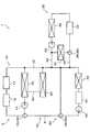
- the vehicle thermal management system 1 includes an apparatus-side coolant circuit 10, a battery-side coolant circuit 20, a heating-side coolant circuit 30, a circuit connection unit 40, and a flow path switching unit 50. And the control unit 60 and the like, and corresponds to the thermal management system according to the present disclosure.
- the device side cooling water circuit 10, the battery side cooling water circuit 20, and the heating side cooling water circuit 30 are cooling water circuits through which cooling water circulates.
- the device side cooling water circuit 10 is a cooling water circuit for adjusting the temperature of a heat generating device mounted on an electric vehicle.
- the battery side cooling water circuit 20 is a cooling water circuit for adjusting the temperature of the battery 21 mounted on the electric vehicle.
- the temperature control side cooling water circuit 5 is configured by the device side cooling water circuit 10 and the battery side cooling water circuit 20.
- the temperature control side cooling water circuit 5 corresponds to the temperature control side heat medium circuit in the present disclosure.
- the heating side cooling water circuit 30 is a cooling water circuit used when heating blowing air in heating mode or dehumidification heating mode.
- the cooling water is a fluid as a heat medium.
- the cooling water is a liquid containing at least ethylene glycol, dimethylpolysiloxane or nanofluid, or an antifreeze liquid.
- the device-side cooling water circuit 10 is a cooling water circuit for adjusting the temperature of the inverter 11 and the motor generator 12 that generate heat with operation, and corresponds to the device-side heat medium circuit in the present disclosure.
- the upper limit temperature of the cooling water circulating through the device-side cooling water circuit 10 is set to, for example, about 65 ° C., due to the nature of the devices such as the inverter 11 and the motor generator 12.
- the apparatus-side cooling water circuit 10 includes an inverter 11, a motor generator 12, an apparatus-side radiator 13, a first water pump 14, and a first switching valve 15. Cooling water as a heat medium is used. It is configured to be recyclable.
- the first water pump 14, the inverter 11, the motor generator 12, the first switching valve 15, and the device-side radiator 13 perform the cooling water circulation in this order. It is arranged in ten.
- the inverter 11 and the motor generator 12 are in-vehicle devices mounted on an electric vehicle, and are heat-generating devices that generate heat as they operate.
- the inverter 11 is a power conversion unit that converts DC power supplied from the battery 21 of the electric vehicle into AC power and outputs the AC power to the motor generator 12.
- the motor generator 12 generates driving force for traveling using the electric power output from the inverter 11, and generates regenerative electric power during deceleration or downhill.
- the inverter 11 and the motor generator 12 radiate the exhaust heat generated as a result of the operation to the cooling water of the device-side cooling water circuit 10. In other words, the inverter 11 and the motor generator 12 supply heat to the cooling water of the device-side cooling water circuit 10.
- the device-side radiator 13 exchanges heat between the cooling water flowing through the inverter 11 and the motor generator 12 and the outside air in the device-side cooling water circuit 10. Outside air is blown to the device-side radiator 13 by an outdoor fan (not shown). Accordingly, the device-side radiator 13 can radiate the heat of the cooling water of the device-side cooling water circuit 10 to the outside air.
- the device-side radiator 13 corresponds to the device-side heat exchanger in the present disclosure.
- the first water pump 14 is a heat medium pump that sucks and discharges the cooling water on the cooling water flow path (that is, the heat medium flow path in the present disclosure) of the device-side cooling water circuit 10.
- the first water pump 14 is an electric pump, and functions as part of a flow rate adjustment unit that adjusts the flow rate of the cooling water circulating in the device-side cooling water circuit 10.
- a first switching valve 15 is connected to the discharge port side of the first water pump 14 via an inverter 11 and a motor generator 12.
- a second connection channel 42 constituting the circuit connection portion 40 is connected to one of the outflow and inlet ports of the first switching valve 15.
- the first water pump 14 sends out the cooling water to the second connection flow path 42 side in the device-side cooling water circuit 10 via the inverter 11 and the motor generator 12.
- the first water pump 14 corresponds to the device-side heat medium pump in the present disclosure.
- the first switching valve 15 is disposed between the motor generator 12 and the device-side radiator 13 in the device-side cooling water circuit 10.
- the first switching valve 15 is constituted by a so-called electromagnetic three-way valve, and has three outflow and inlet ports.
- the inlet / outlet of the cooling water in the device-side radiator 13 is connected to one of the inlet / outlet of the first switching valve 15, and the outlet / inlet of the motor generator 12 is connected to the other outlet / inlet. Is connected.
- the second connection channel 42 is connected to the remaining one of the outflow and inlet ports of the first switching valve 15. That is, the first switching valve 15 is disposed at the connection position between the circulation circuit of the device-side coolant circuit 10 and the second connection flow path 42.
- the first switching valve 15 operates the internal valve body to circulate cooling water in the equipment-side cooling water circuit 10 and stops the circulation of cooling water in the equipment-side cooling water circuit 10 And can be switched.
- the first switching valve 15 can switch the presence or absence of the inflow and outflow of the cooling water with respect to the device-side cooling water circuit 10.
- the operation of the first switching valve 15 is controlled by a control signal output from the control unit 60.
- the said 1st switching valve 15 is corresponded to the 1st switching part in this indication, and comprises a part of flow-path switching part which concerns on this indication.
- the battery side cooling water circuit 20 in the vehicle thermal management system 1 is a cooling water circuit for adjusting the temperature of the battery 21 which generates heat during rapid charging and power utilization, and corresponds to the battery side heat medium circuit in the present disclosure.
- the battery side cooling water circuit 20 includes a battery 21, a chiller 22, a battery side radiator 23, a second water pump 24, and a second switching valve 25. Cooling water as a heat medium circulates It is configured to be possible.
- the second water pump 24, the chiller 22, the battery 21, the second switching valve 25, and the battery side radiator 23 are such that the cooling water is circulated in this order. It is disposed in the circuit 20.
- the battery 21 is a secondary battery that can be charged and discharged.
- a lithium ion battery is employed as the battery 21.
- the battery 21 supplies the charged power to an on-vehicle apparatus such as a traveling electric motor.
- the battery 21 corresponds to the battery in the present disclosure.
- the temperature of the cooling water (i.e., the battery water temperature TW) in the battery side cooling water circuit 20 is determined by the characteristics of the battery 21, and the battery 21 has sufficient performance. It is adjusted to be within the range that can be exhibited.
- the water temperature upper limit value TWu which is the upper limit value of the battery water temperature TW
- the water temperature lower limit value TWl which is the lower limit value of the battery water temperature TW
- the water temperature upper limit value TWu is set to 30 ° C.
- the water temperature lower limit value TWl which is the lower limit value of the battery water temperature TW
- the chiller 22 is one of the components in the vapor compression refrigeration cycle, and is a heat medium cooling heat exchanger that cools the coolant by heat exchange between the low pressure refrigerant and the coolant in the refrigeration cycle.
- the chiller 22 absorbs the heat of the cooling water of the battery side cooling water circuit 20 to the low pressure refrigerant of the refrigeration cycle.
- the chiller 22 corresponds to the chiller in the present disclosure.
- the refrigeration cycle in the first embodiment is a vapor compression refrigeration system having a compressor, a condenser, a water refrigerant heat exchanger 33, a pressure reducing device, an evaporator, a chiller 22, an outdoor heat exchanger, etc. Machine.
- a fluorocarbon-based refrigerant is used as the refrigerant in the refrigeration cycle.
- the refrigeration cycle is a subcritical refrigeration cycle in which the high pressure side refrigerant pressure does not exceed the critical pressure of the refrigerant.
- the battery side radiator 23 exchanges heat between the cooling water flowing through the battery 21 and the chiller 22 and the outside air in the battery side cooling water circuit 20. Outside air is blown to the battery side radiator 23 by an outdoor fan (not shown) as in the device side radiator 13.
- the battery side radiator 23 can radiate the heat which the cooling water of the battery side cooling water circuit 20 has to the open air.
- the battery side radiator 23 corresponds to the battery side heat exchanger in the present disclosure.
- the second water pump 24 is a heat medium pump that sucks in and discharges the cooling water on the cooling water flow path of the battery side cooling water circuit 20.
- the second water pump 24 is an electric pump, and functions as part of a flow rate adjustment unit that adjusts the flow rate of the cooling water circulating in the battery side cooling water circuit 20.
- a second switching valve 25 is connected to the discharge port side of the second water pump 24 via a battery 21 and a chiller 22.
- the first connection flow path 41 constituting the circuit connection portion 40 is connected to one of the outflow / inflow ports of the second switching valve 25.
- the second water pump 24 sends the cooling water to the first connection flow path 41 via the battery 21 and the chiller 22 in the battery side cooling water circuit 20.
- the second water pump 24 corresponds to the battery side heat medium pump in the present disclosure.
- the second switching valve 25 is disposed between the battery 21 and the battery side radiator 23 in the battery side cooling water circuit 20. Similar to the first switching valve 15, the second switching valve 25 is constituted by a so-called electromagnetic three-way valve, and has three outflow and inlet ports.
- the outlet of the cooling water in the battery 21 is connected to one of the inlet and outlet of the second switching valve 25, and the outlet and inlet of the battery side radiator 23 is connected to the other outlet and inlet. It is connected.
- the first connection channel 41 is connected to the remaining one of the outflow and inlet ports of the second switching valve 25. That is, the second switching valve 25 is disposed at the connection position between the circulation circuit of the battery side cooling water circuit 20 and the first connection flow path 41.
- the second switching valve 25 operates the internal valve body to circulate the cooling water in the battery side cooling water circuit 20 and stops the circulation of the cooling water in the battery side cooling water circuit 20. And can be switched.
- the second switching valve 25 can switch the presence or absence of the inflow and outflow of the cooling water to and from the battery side cooling water circuit 20.
- the operation of the second switching valve 25 is controlled by a control signal output from the control unit 60.
- the said 2nd switching valve 25 is corresponded to the 2nd switching part in this indication, and comprises a part of flow-path switching part which concerns on this indication.
- the heating side cooling water circuit 30 which comprises the vehicle thermal management system 1 is a cooling water circuit used when heating the vehicle interior which is air-conditioning object space, and is equivalent to the heating side heat medium circuit in this indication.
- the heating side cooling water circuit 30 has a heater core 31, a heating device 32, a water refrigerant heat exchanger 33, a third water pump 34, and a third switching valve 35, and is used as a heat medium for cooling. Water is configured to be recyclable.
- the third water pump 34, the water refrigerant heat exchanger 33, the heating device 32, the third switching valve 35, and the heater core 31 perform the heating so that the cooling water circulates in this order. It is disposed in the side cooling water circuit 30.
- the heater core 31 is an air heating heat exchanger that heat-exchanges the cooling water of the heating side cooling water circuit 30 with the air blown into the vehicle interior to heat the air blown into the vehicle interior.
- the heat of the cooling water of the heating side cooling water circuit 30 is dissipated with respect to the blowing air blown into the vehicle compartment which is the space to be air conditioned.
- the heat of the cooling water is dissipated to the blowing air by the heater core 31, so that the blowing air can be warmed, and the heating of the vehicle interior and the dehumidifying heating can be performed.
- the heater core 31 corresponds to the heater core in the present disclosure.
- the heating device 32 is a heating device that heats the cooling water flowing through the heating side cooling water circuit 30.
- the heating device 32 includes, for example, a PTC element or a nichrome wire, and generates heat when the control power output from the control unit 60 is supplied to heat the cooling water.
- the heating capacity for the cooling water by the heating device 32 is controlled by the control power output from the control unit 60. That is, the heating device 32 functions as a heating device in the present disclosure.
- the water refrigerant heat exchanger 33 is one of the components of the refrigeration cycle (not shown) like the chiller 22 described above, and is a high pressure refrigerant compressed by the compressor of the refrigeration cycle and cooling of the heating side cooling water circuit 30 Heat is exchanged with water to dissipate heat to the cooling water of the heating side cooling water circuit 30.
- the cooling water of the heating side cooling water circuit 30 is heated by using the heat of the high pressure refrigerant as a heat source. That is, according to the heat management system 1 for vehicles concerned, blowing air can be heated by using the high-pressure refrigerant of a frozen cycle as a heat source at least in heating mode or dehumidification heating mode.
- the water refrigerant heat exchanger 33 corresponds to the refrigerant heat medium heat exchanger in the present disclosure.
- the third water pump 34 is a heat medium pump that sucks and discharges the cooling water on the cooling water flow path of the heating side cooling water circuit 30.
- the third water pump 34 is an electric pump, and functions as part of a flow rate adjustment unit that adjusts the flow rate of the cooling water circulating through the heating side cooling water circuit 30.
- the water refrigerant heat exchanger 33, the heating device 32, and the heater core 31 are connected to the discharge port side of the third water pump 34. Therefore, the third water pump 34 can send the coolant of the heating side coolant circuit 30 so as to pass through the water refrigerant heat exchanger 33, the heating device 32, and the heater core 31.
- the third water pump 34 corresponds to the heating side heat medium pump in the present disclosure.
- a third switching valve 35 is disposed between the heating device 32 and the heater core 31 in the heating side cooling water circuit 30. Similar to the first switching valve 15 and the second switching valve 25, the third switching valve 35 is constituted by a so-called electromagnetic three-way valve, and has three outflow and inlet ports.
- an outlet / inlet of cooling water in the heater core 31 is connected to one of the inlet / outlet of the third switching valve 35. Further, the other inlet / outlet of the third switching valve 35 is connected to the outlet / inlet of the cooling water passage in the heating device 32.
- the fourth connection flow path 44 that constitutes the circuit connection portion 40 is connected to one remaining outflow port of the third switching valve 35. That is, the third switching valve 35 is disposed at the connection position between the circulation circuit of the heating side cooling water circuit 30 and the fourth connection flow path 44.
- the third switching valve 35 operates the internal valve element to circulate the cooling water in the heating side cooling water circuit 30 and stops the circulation of the cooling water in the heating side cooling water circuit 30. And can be switched.
- the third switching valve 35 can switch the presence or absence of the outflow / inflow of the cooling water to the heating side cooling water circuit 30.
- the operation of the third switching valve 35 is controlled by a control signal output from the control unit 60.
- the said 3rd switching valve 35 is corresponded to the 3rd switching part in this indication, and comprises a part of flow-path switching part which concerns on this indication.
- the circuit connection unit 40 is connected to the apparatus-side cooling water circuit 10, the battery-side cooling water circuit 20, and the heating-side cooling water circuit 30 by a cooling water flow path that allows cooling water as a heat medium to flow in and out mutually. It is configured.
- the circuit connection unit 40 in the first embodiment includes a first connection channel 41, a second connection channel 42, a third connection channel 43, and a fourth connection channel 44. And a bypass flow passage 45.
- the circuit connection unit 40 corresponds to the circuit connection unit in the present disclosure.
- the first connection flow path 41 is a cooling water flow path connecting the device-side cooling water circuit 10 and the battery-side cooling water circuit 20, and the cooling water flow between the device-side cooling water circuit 10 and the battery-side cooling water circuit 20 It enables inflow and outflow.
- the said 1st connection flow path 41 is corresponded to the 1st connection flow path in this indication, and comprises a part of circuit connection part.
- one end of the first connection channel 41 is connected between the outlet / inlet of the device-side radiator 13 and the suction port of the first water pump 14 in the device-side cooling water circuit 10. . Further, as described above, the other end portion of the first connection flow channel 41 is connected to one of the outflow and inlet ports of the second switching valve 25 of the battery side cooling water circuit 20.
- the second connection flow path 42 is a cooling water flow path connecting the device side cooling water circuit 10 and the battery side cooling water circuit 20 at a position different from the first connection flow path 41, and the battery side cooling water circuit 20 and the other It enables the outflow and inflow of cooling water between the cooling water circuits of
- the second connection channel 42 corresponds to the second connection channel in the present disclosure, and constitutes a part of the circuit connection portion.
- One end of the second connection flow channel 42 is connected to one of the outflow and inlet ports of the first switching valve 15 of the device-side cooling water circuit 10.
- the other end portion of the second connection flow path 42 is connected between the battery side radiator 23 and the suction port of the second water pump 24 in the battery side cooling water circuit 20 as shown in FIG. 1.
- the temperature adjustment side cooling water circuit 5 in the vehicle thermal management system 1 connects the device side cooling water circuit 10 and the battery side cooling water circuit 20 by the first connection flow passage 41 and the second connection flow passage 42. It consists of
- the third connection flow path 43 is a cooling water flow path connecting the temperature adjustment side cooling water circuit 5 and the heating side cooling water circuit 30, and between the temperature adjustment side cooling water circuit 5 and the heating side cooling water circuit 30. It enables the inflow and outflow of cooling water.
- the said 3rd connection flow path 43 is corresponded to the 3rd connection flow path in this indication, and comprises a part of circuit connection part.
- one end of the third connection channel 43 is connected to the second connection channel 42 in the temperature adjustment side cooling water circuit 5.
- the other end of the third connection channel 43 is connected between the outlet / inlet of the heater core 31 in the heating side cooling water circuit 30 and the suction port of the third water pump 34.
- the fourth connection flow path 44 is a cooling water flow path connecting the temperature adjustment side cooling water circuit 5 and the heating side cooling water circuit 30 at a position different from the third connection flow path 43, and the temperature adjustment side cooling water circuit
- the cooling water can be flowed in and out between the heating water cooling circuit 5 and the heating side cooling water circuit 30.
- the said 4th connection flow path 44 is corresponded to the 4th connection flow path in this indication, and comprises a part of circuit connection part.
- one end portion of the fourth connection flow channel 44 is connected to the battery side cooling water circuit 20 side of the connection position of the third connection flow channel 43 in the second connection flow channel 42.
- the other end of the fourth connection channel 44 is connected to one of the outflow and inlet ports of the third switching valve 35 of the heating side cooling water circuit 30.
- the bypass channel 45 is a cooling water channel connected to the first connection channel 41 and the second connection channel 42. One end of the bypass flow path 45 is connected to an intermediate position in the device-side cooling water circuit 10 and the battery-side cooling water circuit 20 in the first connection flow path 41.
- the other end of the bypass flow path 45 is connected to an intermediate position in the device-side cooling water circuit 10 and the battery-side cooling water circuit 20 in the second connection flow path 42.
- the other end of the bypass flow path 45 is the connection position of the second connection flow path 42 and the third connection flow path 43, and the connection position of the second connection flow path 42 and the fourth connection flow path 44. And is connected to the second connection channel 42.
- the vehicle thermal management system 1 passes the flow of the cooling water having passed through the battery 21 and the like in the battery side cooling water circuit 20 through the bypass flow passage 45.
- the battery side radiator 23 can be bypassed. That is, the vehicle thermal management system 1 can suppress the amount of heat released to the outside air by the battery side radiator 23.
- the flow path switching unit 50 is configured to switch the flow of the cooling water in the circuit connection unit 40 described above, and the first switching valve 15 of the device side cooling water circuit 10 and the first of the battery side cooling water circuit 20 A second switching valve 25 and a third switching valve 35 of the heating side cooling water circuit 30 are provided.
- the flow path switching unit 50 includes the first switching valve 15, the second switching valve 25, and the third switching valve 35 in accordance with the operation states of the first water pump 14, the second water pump 24, and the third water pump 34. By combining the states, it is possible to switch the inflow and outflow of the cooling water with respect to the device side cooling water circuit 10, the battery side cooling water circuit 20, and the heating side cooling water circuit 30.
- the first switching valve 15, the second switching valve 25, and the third switching valve 35 are configured by the electromagnetic three-way valve.
- the first switching valve 15 operates the valve body to allow the flow of cooling water into and out of the equipment side cooling water circuit 10, and the state of blocking the flow of cooling water into and out of the equipment side cooling water circuit 10 Can be switched.
- the second switching valve 25 operates the valve body to shut off the flow of the cooling water into and out of the battery side cooling water circuit 20 and the state of permitting the flow of the cooling water into and out of the battery side cooling water circuit 20. It is possible to switch between states.
- the third switching valve 35 operates the valve body to shut off the flow of cooling water into and out of the heating side cooling water circuit 30 while permitting the flow of cooling water into and out of the heating side cooling water circuit 30. It is possible to switch between states.
- the vehicle thermal management system 1 includes a control unit 60 for controlling the operation of the control target device in the vehicle thermal management system 1.
- the control unit 60 is configured of a known microcomputer including a CPU, a ROM, a RAM, and the like, and peripheral circuits thereof.
- the control unit 60 corresponds to the control unit in the present disclosure.
- control unit 60 performs various operations and processes based on the control program stored in the ROM, and controls the operation of various control target devices connected to the output side.
- the control contents of the control program will be described in detail later with reference to FIG.
- the devices to be controlled by the control unit 60 include a first water pump 14, a first switching valve 15, a second water pump 24, a second switching valve 25, a third water pump 34, and a third switching valve. Contains 35.
- the vehicle thermal management system 1 can control the flow of the cooling water in the vehicle thermal management system 1 in a desired mode by controlling the operation of these control target devices by the control unit 60.
- a battery water temperature sensor 61 and an outside air temperature sensor 62 are connected to the input side of the control unit 60. As shown in FIG. 1, the battery coolant temperature sensor 61 is disposed in the coolant flow path between the battery 21 and the chiller 22 in the battery side coolant circuit 20.
- the battery water temperature sensor 61 detects the temperature of the cooling water flowing through the battery side cooling water circuit 20 as the battery water temperature TW.
- the outside air temperature sensor 62 is an outside air temperature detection unit that detects an outside temperature (outside air temperature) Tam of the electric vehicle.
- the control unit 60 performs control related to the operation of the refrigeration cycle (not shown) and performs control related to the air volume of the blowing air blown into the vehicle compartment. That is, the control unit 60 performs operation control of the compressor, the pressure reducing device, and the blower that constitute the refrigeration cycle, and switching control of the refrigerant circuit in the refrigeration cycle. Further, on the input side of the control unit 60, a sensor group for various air conditioning control such as an internal air temperature sensor (not shown) is connected.
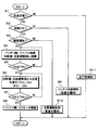
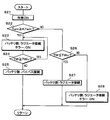
- the flowcharts illustrated in FIG. 2 and the like are executed by the control unit 60 after executing a predetermined initialization process when the entire system of the electric vehicle including the vehicle thermal management system 1 is started (started). And the control by the said flowchart is repeatedly performed while the thermal management system 1 for vehicles is starting.
- step S1 it is determined whether or not the battery 21 in the electric vehicle is rapidly charged. If the rapid charging of the battery 21 is being performed, the process proceeds to step S2, and if not, the process proceeds to traveling control in step S11. The contents of the on-running control will be described later.
- step S2 in the heat management system 1 for a vehicle, it is determined whether the air conditioning inside the vehicle compartment is ON. If the interior air conditioning is ON, the process proceeds to step S3, and if not, the process proceeds to step S9. In step S9, battery cooling control at the time of rapid charging of the battery 21 is performed. The control contents of step S9 will be described in detail later.
- step S3 If it transfers to step S3, it will be judged whether the content of vehicle interior air conditioning is heating operation. If the vehicle interior air conditioning is heating operation, the process proceeds to step S4, and if it is not heating operation, the process proceeds to step S10. In step S10, cooling operation control at the time of rapid charge of the battery 21 is performed. The control contents of step S10 will be described later with reference to the drawings.
- control in step S4 to step S8 are control in the case where the passenger compartment is heated at the time of rapid charging of the battery 21.
- the vehicle heat management system 1 when heating the vehicle interior, it is necessary to heat the blown air supplied into the vehicle interior by heat exchange in the heater core 31.
- the cooling water passing through the heater core 31 of the heating side cooling water circuit 30 needs to have a certain amount of heat.
- the battery 21 when the battery 21 is rapidly charged, the battery 21 generates heat. In the battery side cooling water circuit 20, the cooling water passing through the battery 21 is heated by the heat generated by the rapid charging.
- step S4 the operation of the flow path switching unit 50 and the like is controlled in order to heat the vehicle interior by effectively utilizing the heat generated during rapid charging of the battery 21.
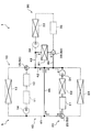
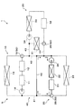
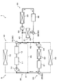
- FIG. 3 shows the state of the vehicle thermal management system 1 under the control of step S4, and is an explanatory view showing the flow of the cooling water in the initial stage of the heating mode at the time of quick charge.
- circulating is shown with the continuous line among the cooling water flow paths of the thermal management system 1 for vehicles, and the part with which the cooling water remains is shown with the broken line.
- the control target devices in operation are indicated by solid lines, and the control target devices in which operation is stopped are indicated by broken lines.
- step S 4 the second water pump 24 pressure-feeds the cooling water from the discharge port, and the first water pump 14 and the third water pump 34 are controlled to be kept stopped. . Further, since the operation of the refrigeration cycle is also stopped, heat exchange in the chiller 22 and the water refrigerant heat exchanger 33 is not performed, and the heating device 32 is also stopped.
- the first switching valve 15 is controlled so as to close the second connection flow path 42 and to communicate the motor generator 12 side with the device-side radiator 13 side.
- the second switching valve 25 communicates with the second connection flow path 42 side and the battery 21 side, and is controlled so as to close the battery side radiator 23 side.
- the third switching valve 35 is controlled to communicate all of the heater core 31 side, the heating device 32 side, and the fourth connection flow path 44 side.
- the device-side coolant circuit 10 and the heating-side coolant circuit 30 are connected via the circuit connection unit 40. become. That is, the battery side cooling water circuit 20 and the heating side cooling water circuit 30 are controlled to the heat medium connection state in the present disclosure.
- the cooling water flows from the second water pump 24 ⁇ the chiller 22 ⁇ the battery 21 ⁇ the first connection channel 41 ⁇ the bypass channel 45 ⁇ the second connection channel 42, the battery The water is circulated in the side cooling water circuit 20.
- the heat generated in the battery 21 due to the rapid charging is absorbed by the cooling water and transferred together with the cooling water.
- the cooling water flowing into the second connection flow channel 42 flows into the heating side cooling water circuit 30 via the third connection flow channel 43.
- the cooling water flowing out of the third connection channel 43 has a flow of heater core 31 ⁇ third switching valve 35, and third water pump 34 ⁇ water refrigerant heat exchanger 33 ⁇ heating device 32 ⁇ third It branches into the flow of 3 switching valve 35, and flows in parallel.
- the vehicle thermal management system 1 can allow the cooling water warmed by the exhaust heat from the rapid charging of the battery 21 to pass through the heater core 31. That is, the vehicle thermal management system 1 can effectively utilize the exhaust heat of the battery 21 to warm the heating and heating-side coolant circuit 30 side of the vehicle interior.
- the vehicle thermal management system 1 performs heating of the interior of the vehicle without operating the refrigeration cycle and the heating device 32, it is possible to reduce power consumption required for heating the interior of the vehicle. That is, the vehicle thermal management system 1 can enhance the charging efficiency of the battery 21 when performing the rapid charging and the heating in the passenger compartment in parallel.
- step S4 for example, when the immediate heating setting is set by the user or the like, various control target devices are controlled so as to be the flow of the cooling water shown in FIG. Unlike the case of FIG. 3 described above, the third switching valve 35 communicates with the heater core 31 side and the fourth connection flow path 44 side, and is controlled so as to close the heating device 32 side.
- the vehicle thermal management system 1 can use all the heat generated in the battery 21 due to the rapid charging for heating the vehicle interior, so in a shorter period of time than the case shown in FIG. It can warm the passenger compartment and improve comfort.
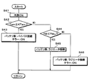
- step S5 in the state of FIG. 3 or FIG. 4, it is determined whether battery water temperature TW is equal to or higher than water temperature upper limit value TWu. If the battery water temperature TW is equal to or higher than the water temperature upper limit value TWu, the process proceeds to step S6. If not, the process returns to step S4.
- the state in which the battery water temperature TW becomes equal to or higher than the water temperature upper limit value TWu after shifting to step S4 is referred to as the middle period of the heating mode during rapid charge.
- step S6 the operation of the flow path switching unit 50 and the like is controlled in order to efficiently perform temperature control of the battery 21 at the time of rapid charge and heating the vehicle interior in parallel.
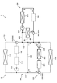
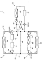
- FIG. 5 shows the state of the vehicle thermal management system 1 under the control of step S6, and is an explanatory view showing the flow of cooling water in the middle stage of the heating mode at the time of quick charge.
- step S6 the operation of each control target device is controlled so that the state of FIG. 3 or 4 according to step S4 is changed to the state of FIG.
- the chiller 22 is controlled so that the low pressure refrigerant of the refrigeration cycle flows, and the low pressure refrigerant absorbs heat of the cooling water in the battery side cooling water circuit 20.
- the 3rd switching valve 35 is controlled so that the heater core 31 side and the heating device 32 side may be connected, and the 4th connection channel 44 side may be closed.
- the third water pump 34 pumps the cooling water of the heating side cooling water circuit 30.
- the water refrigerant heat exchanger 33 is controlled so that the high pressure refrigerant of the refrigeration cycle flows, and heats the cooling water of the heating side cooling water circuit 30 by the heat of the high pressure refrigerant.
- the operation of the other control target device in the vehicle thermal management system 1 is the same as in the state of FIG. 3 or FIG. 4.
- independent cooling water is circulated in the battery side cooling water circuit 20 and the heating side cooling water circuit 30. Become. That is, the battery side cooling water circuit 20 and the heating side cooling water circuit 30 are controlled to the circulation state in the present disclosure.
- the cooling water flows from the second water pump 24 ⁇ the chiller 22 ⁇ the battery 21 ⁇ the first connection channel 41 ⁇ the bypass channel 45 ⁇ the second connection channel 42, the battery The water is circulated in the side cooling water circuit 20.
- the heat generated in the battery 21 due to the rapid charging is absorbed by the cooling water and transferred together with the cooling water. Then, in the chiller 22, the heat of the cooling water is absorbed by the low pressure refrigerant of the refrigeration cycle. Therefore, the battery side cooling water circuit 20 can cool the battery 21 which generates heat by rapid charging by the cooling water.
- the cooling water flows from the third water pump 34 ⁇ the water refrigerant heat exchanger 33 ⁇ the heating device 32 ⁇ the third switching valve 35 ⁇ the heater core 31 by the operation of the third water pump 34. , And circulate through the heating side cooling water circuit 30.
- the cooling water When passing through the water refrigerant heat exchanger 33, the cooling water is heated by the high pressure refrigerant of the refrigeration cycle. That is, the said thermal management system 1 for vehicles can heat up a cooling water by pumping up the heat which arose by the rapid charge of the battery 21 by a refrigerating cycle.
- the said vehicle thermal management system 1 can perform vehicle interior heating, using the heat which arose by the rapid charge of the battery 21 effectively.
- step S6 the vehicle thermal management system 1 recovers the heat generated in the battery 21 by the chiller 22, and the heating side cooling water circuit 30 through the refrigeration cycle and the water refrigerant heat exchanger 33. You can warm the side indirectly.
- step S7 in the state of FIG. 5, it will be judged whether battery water temperature TW is more than the water temperature upper limit TWu. If the battery water temperature TW is equal to or higher than the water temperature upper limit value TWu, the process proceeds to step S8. If not, the process returns to step S6.
- step S8 the operation of the flow path switching unit 50 and the like is controlled in order to efficiently perform temperature control of the battery 21 at the time of rapid charging and heating the vehicle interior in parallel.
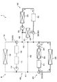
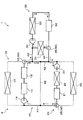
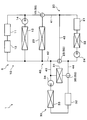
- FIG. 6 shows the state of the vehicle thermal management system 1 under the control of step S8, and is an explanatory view showing the flow of the cooling water in the late stage of the heating mode at the time of quick charge.
- step S8 the operation of each control target device is controlled so as to change from the state of FIG. 5 in step S6 to the state of FIG.
- the second switching valve 25 communicates the battery 21 side with the battery side radiator 23 side, and is controlled so as to close the second connection flow path 42 side.
- the operation of the other control target device in the vehicle thermal management system 1 is the same as in the state of FIG.
- independent cooling water is circulated in the battery side cooling water circuit 20 and the heating side cooling water circuit 30. Become. That is, the battery side cooling water circuit 20 and the heating side cooling water circuit 30 are controlled to the circulation state in the present disclosure.
- the cooling water flows from the second water pump 24 ⁇ the chiller 22 ⁇ the battery 21 ⁇ the battery side radiator 23 and circulates in the battery side cooling water circuit 20.
- the heat generated in the battery 21 due to the rapid charging is absorbed by the cooling water and transferred together with the cooling water. Then, in the chiller 22, the heat of the cooling water is absorbed by the low pressure refrigerant of the refrigeration cycle.
- the battery side cooling water circuit 20 can cool the battery 21 which generates heat by rapid charging by the cooling water.
- the thermal management system 1 for vehicles can cool the cooling water of the battery side cooling water circuit 20 using the heat absorption effect in the chiller 22 and the heat radiation to the open air in the battery side radiator 23.
- the vehicle thermal management system 1 can warm the temperature of the cooling water of the battery side cooling water circuit 20 more than the water temperature upper limit value TWu by the heat of the battery 21 accompanying rapid charging. Correspondingly, the temperature of the cooling water can be properly adjusted.
- the vehicle thermal management system 1 controls the operation of the flow path switching unit 50. Can correspond to this condition.
- the second switching valve 25 is controlled so that all of the battery 21 side, the battery side radiator 23 side, and the second connection flow path 42 side communicate with each other.
- the first switching valve 15 communicates with the device-side radiator 13 side and the second connection flow path 42 side, and is controlled to close the motor generator 12 side.
- the cooling water flows from the second water pump 24 ⁇ the chiller 22 ⁇ the battery 21 ⁇ the second switching valve 25 and then the battery side radiator 23 side and the first connection flow path Branch to the 41 side. Therefore, the cooling water which has flowed into the battery side radiator 23 dissipates the heat to the outside air.
- the cooling water having flowed to the side of the first connection channel 41 flows into the device-side radiator 13 via the first connection channel 41. Therefore, the cooling water that has flowed into the device-side radiator 13 dissipates its heat to the outside air. Thereafter, the cooling water flows from the first water pump 14 to the second connection channel 42 and reaches the suction port of the second water pump 24.
- the battery using the heat absorbing action of the chiller 22 and the heat dissipation to the outside air of the device-side radiator 13 and the battery-side radiator 23
- the cooling water of the side cooling water circuit 20 can be cooled.
- step S9 battery cooling control at the time of quick charge is performed. Specifically, the flow of the cooling water in the battery side cooling water circuit 20 is switched according to the battery water temperature TW of the battery water temperature sensor 61 and the outside air temperature Tam by the outside air temperature sensor 62, and the heat generated by the rapid charge is dissipated .
- the heat radiation amount to the outside air using the battery side radiator 23 and the device side radiator 13 and the heat absorption amount by the chiller 22 are changed to change the temperature of the cooling water passing through the battery 21 adjust.
- the battery 21 which generates heat due to rapid charging can be cooled by the cooling water adjusted to an appropriate temperature.
- step S10 cooling operation control during rapid charging is performed.
- the operation of each control target device of the vehicle thermal management system 1 is controlled according to the flowchart shown in FIG. The control contents in step S10 will be described in detail later with reference to FIG.
- step S11 control at the time of driving
- the operation of each control target device of the vehicle thermal management system 1 is controlled according to the flowchart shown in FIG. The control contents of step S11 will be described in detail later with reference to FIG.
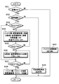
- step S21 When cooling operation control at the time of rapid charging in step S10 is started, first, in step S21, the operation of the refrigeration cycle and the blower is switched to the cooling mode as shown in FIG. That is, in step S21, in the refrigeration cycle, the low-pressure refrigerant reduced in pressure by the pressure reducing device flows into the evaporator, and the evaporator controls heat exchange with the air blown into the vehicle compartment by the blower. Be done.
- step S22 using the detection result of the outside air temperature sensor 62, it is determined whether the outside air temperature Tam is equal to or more than a predetermined outside air temperature Ktam.
- the standard outside temperature KTam is a reference value for determining whether the outside temperature Tam is high temperature, and is set to, for example, 30 ° C. If the outside air temperature Tam is equal to or higher than the outside air temperature KTam, the process proceeds to step S23. If not, the process proceeds to step S26.
- step S23 the operation of the flow path switching unit 50 and the like is controlled in order to cool the interior of the vehicle while cooling the battery 21 that generates heat due to rapid charging.
- the second water pump 24 delivers the cooling water of the battery side cooling water circuit 20
- the second switching valve 25 is on the battery 21 side and the battery side radiator 23 side.
- the first switching valve 15 is controlled so as to close the side of the inverter 11 and the motor generator 12.
- control unit 60 controls the operation of the refrigeration cycle so that the heat of the cooling water of the battery side cooling water circuit 20 is absorbed by the low pressure refrigerant of the refrigeration cycle by the chiller 22.
- the heat absorbed by the chiller 22 is radiated to the outside air by the outdoor heat exchanger connected to the refrigeration cycle.
- step S23 the flow of the cooling water in the battery side cooling water circuit 20 is switched.
- the vehicle thermal management system 1 can put the battery side cooling water circuit 20 in a circulating state, and by using the refrigeration cycle and the battery side radiator 23 and the device side radiator 13, The temperature of the cooling water of the battery side cooling water circuit 20 can be adjusted appropriately. Thereby, the said vehicle thermal management system 1 can implement
- step S24 it is determined using the detection result of the battery water temperature sensor 61 whether the battery water temperature TW is equal to or higher than the water temperature upper limit value TWu. If the battery water temperature TW is equal to or higher than the water temperature upper limit value TWu, the process returns to step S23, and the heat absorption by the chiller 22 is combined with the heat radiation by the battery side radiator 23 and the device side radiator 13 to lower the temperature of the cooling water. If not, the process proceeds to step S25.
- step S25 the operation of the flow path switching unit 50 and the like is controlled in response to the battery water temperature TW falling below the water temperature upper limit value TWu.
- the second switching valve 25 communicates the battery 21 side and the first connection flow path 41 side, and is controlled so as to close the battery side radiator 23 side.
- the operation of the other control target devices is the same as in step S23.
- the cooling water is supplied from the second water pump 24 ⁇ chiller 22 ⁇ battery 21 ⁇ second switching valve 25 ⁇ first connection flow path 41 ⁇ bypass flow path It flows in the order of 45 ⁇ the second connection flow path 42 and circulates in the battery side cooling water circuit 20.
- step S25 the vehicle thermal management system 1 cools the cooling water by utilizing the heat absorption effect of the chiller 22, and the battery side radiator 23 and the device side radiator 13 do not release the heat to the outside air. .
- the vehicle thermal management system 1 can suppress the cooling capacity of the battery 21 by the battery side cooling water circuit 20 more than in the case of step S23, and adjusts the temperature of the battery 21 during rapid charge to an appropriate temperature. can do.
- step S26 it will be judged whether battery water temperature TW is below water temperature upper limit TWu. If the battery water temperature TW is less than or equal to the water temperature upper limit TWu, the process proceeds to step S27. If not, the process proceeds to step S28.
- step S27 in order to cope with the situation where the outside air temperature Tam is low and the battery water temperature TW is lower than the water temperature upper limit TWu, the operation of the flow path switching unit 50 etc. is controlled. Specifically, in the battery side cooling water circuit 20, the second water pump 24 is operated. Also, the operation of the refrigeration cycle is controlled so that the low pressure refrigerant of the refrigeration cycle does not flow into the chiller 22.
- the second switching valve 25 communicates the battery 21 side, the battery side radiator 23 side, and the device side radiator 13, and the first switching valve 15 is controlled to close the inverter 11 and the motor generator 12 side.
- the cooling water flows in the order of the second water pump 24 ⁇ chiller 22 ⁇ battery 21 ⁇ battery side radiator 23 and the equipment side radiator 13 and circulates in the battery side cooling water circuit 20.
- the heat generated in the battery 21 by the rapid charging is dissipated from the battery side radiator 23 and the device side radiator 13 through the cooling water of the battery side cooling water circuit 20.
- step S28 in order to cope with the situation where the outside air temperature Tam is low and the battery water temperature is higher than the water temperature upper limit value TWu, the operation of the flow path switching unit 50 etc. is controlled. Specifically, in the battery side cooling water circuit 20, the second water pump 24 is operated, and the second switching valve 25 connects the battery 21 side, the battery side radiator 23 side, and the device side radiator 13 side, The 1 switching valve 15 is controlled to close the side of the inverter 11 and the motor generator 12.
- the cooling water flows in the order of the second water pump 24 ⁇ chiller 22 ⁇ battery 21 ⁇ battery side radiator 23 and the equipment side radiator 13 and circulates in the battery side cooling water circuit 20.
- control unit 60 controls the operation of the refrigeration cycle so that the heat of the cooling water of the battery side cooling water circuit 20 is absorbed by the low pressure refrigerant of the refrigeration cycle by the chiller 22.
- the heat absorbed by the chiller 22 is radiated to the outside air by the outdoor heat exchanger connected to the refrigeration cycle.
- step S28 in the battery side cooling water circuit 20, the battery 21 is discharged rapidly to the outside air in the battery side radiator 23 and the device side radiator 13 due to quick charging, and the heat absorbing action in the chiller 22. It is cooled through the cooling water.
- control contents to be executed in the traveling control in step S11 will be described with reference to FIG. As described above, this traveling control is performed when the electric vehicle is traveling.
- the inverter 11 and the motor generator 12 generate heat as the electric vehicle travels, and the battery 21 also generates heat as the electric power is used.
- the vehicle thermal management system 1 effectively uses the heat generated in the heat generating devices such as the inverter 11 and the motor generator 12 and the heat of the battery 21 accompanying the use of electric power. Each component in the thermal management system 1 is adjusted to an appropriate temperature.
- step 31 it is determined whether or not the interior air conditioning is ON when the electric vehicle is traveling. If the interior air conditioning is ON, the process proceeds to step S32, and if not, the process proceeds to step S40.
- step S40 battery cooling control is performed when the electric vehicle travels. The control contents of step S40 will be described in detail later.
- step S32 it is determined whether the content of the air conditioning in the passenger compartment is the heating operation. If the vehicle interior air conditioning is the heating operation, the process proceeds to step S33, and if the heating operation is not performed, the process proceeds to step S39. In step S39, cooling operation control is performed when the electric vehicle travels. The control contents of step S39 will be described later with reference to the drawings.
- control contents in the following steps S33 to S38 are control in the case where the passenger compartment is heated when the electric vehicle travels.
- the control unit 60 controls the operation of various control target devices in order to effectively use the heat generated by the inverter 11, the motor generator 12, and the battery 21 as the electric vehicle travels for heating the vehicle interior.
- step S33 using the detection result of the battery water temperature sensor 61, it is determined whether the battery water temperature TW is less than or equal to the water temperature lower limit value TW1. If the battery water temperature TW is equal to or lower than the water temperature lower limit value TW1, the process proceeds to step S34. If not, the process proceeds to S37.
- step S34 the operation of the flow path switching unit 50 and the like is controlled in order to heat the vehicle interior by effectively utilizing the heat generated in the heat-generating equipment such as the inverter 11 and the like and the battery 21.
- the battery water temperature TW is in the state of being equal to or lower than the water temperature lower limit value TWl. Therefore, in this case, in order to heat the blowing air by the heater core 31, a period for raising the temperature of the low temperature cooling water is required in the vehicle thermal management system 1.
- the first water pump 14 pressure-feeds the cooling water from the discharge port.
- the first switching valve 15 communicates the motor generator 12 side with the second connection flow path 42 side, and is controlled to close the device-side radiator 13 side.
- the second water pump 24 pumps the cooling water from the discharge port.
- the second switching valve 25 communicates the battery 21 side with the first connection flow path 41, and is controlled to close the battery side radiator 23 side. At this time, the refrigeration cycle is controlled so that the low pressure refrigerant does not flow into the chiller 22.
- the third water pump 34 pumps cooling water from the discharge port, and the third switching valve 35 is on the heater core 31 side, the heating device 32 side, and the fourth connection flow path 44. It is controlled to connect all the sides.
- the heating device 32 is controlled to heat the cooling water with a predetermined calorific value.
- the refrigeration cycle is controlled such that the high pressure refrigerant of the refrigeration cycle flows into the water refrigerant heat exchanger 33.
- the refrigeration cycle absorbs heat from the outside air by the outdoor heat exchanger (not shown), and the water refrigerant heat exchanger 33 dissipates the heat of the high pressure refrigerant to the cooling water.
- the cooling water is heated by the heating device 32 and the water refrigerant heat exchanger 33.
- the device-side cooling water circuit 10 By thus controlling the operation of the circuit connection unit 40, in the vehicle thermal management system 1, the device-side cooling water circuit 10, the battery-side cooling water circuit 20, and the heating-side cooling water circuit 30 It will be connected via That is, the device side cooling water circuit 10, the battery side cooling water circuit 20, and the heating side cooling water circuit 30 are controlled to the heat medium connection state in the present disclosure.
- the cooling water is processed by the first water pump 14 and the second water pump 24 so that the first water pump 14 ⁇ the inverter 11 ⁇ the motor generator 12 ⁇ the first switching valve 15 ⁇
- the third connection flow channel 43 and the fourth connection flow channel 44 are connected to the second connection flow channel 42, and the third water pump 34 is operating. Therefore, part of the cooling water flowing through the second connection flow channel 42 branches to the third connection flow channel 43 side.
- a part of the cooling water flowing out of the third connection flow path 43 flows from the third water pump 34 ⁇ the water refrigerant heat exchanger 33 ⁇ the heating device 32 ⁇ the third switching valve 35 ⁇ the heater core 31.
- the cooling water heated by the heating device 32 and the water refrigerant heat exchanger 33 passes through the heater core 31, and the blown air can be heated.
- part of the cooling water flowing into the third switching valve 35 flows into the fourth connection flow channel 44 and merges with the cooling water flowing through the second connection flow channel 42 on the temperature adjustment side cooling water circuit 5 side. .
- the vehicle thermal management system 1 can utilize the exhaust heat of the heat-generating device such as the inverter 11 or the like and the battery 21 generated when the electric vehicle travels, for heating the vehicle interior via the cooling water.
- the vehicle thermal management system 1 supplies the exhaust heat of the heat generating device such as the inverter 11 or the like generated during traveling of the electric vehicle or the battery 21 to the heating side cooling water circuit 30 via the cooling water, The components on the circuit 30 side and the entire circuit can be warmed.
- the vehicle thermal management system 1 can cope with the case where the passenger compartment is immediately heated while the electric vehicle is traveling.
- step S35 in the state shown in FIG. 11, it is determined whether battery water temperature TW is equal to or higher than water temperature lower limit value TW1. If the battery water temperature TW is equal to or higher than the water temperature lower limit value TW1, the cooling water circulating in the vehicle thermal management system 1 is sufficiently warmed, so the process proceeds to step S36. Otherwise, the process returns to step S34 .
- step S36 the cooling water on the heating-side cooling water circuit 30 side is sufficiently warmed, and the diagram in step S34 is performed in order to perform heating of the vehicle interior and temperature control of the heating device such as the inverter 11 etc. and the battery 21 in parallel.
- the operation of each control target device is controlled so that the state of 11 changes to the state of FIG.
- the third switching valve 35 is controlled to communicate the heater core 31 side with the heating device 32 side and to close the fourth connection flow path 44 side.
- the heating device 32, the water refrigerant heat exchanger 33, and the third water pump 34 are operating.
- the heating side cooling water circuit 30 is separated from the temperature adjustment side cooling water circuit 5 side with respect to the flow of the cooling water in the vehicle thermal management system 1, and is circulated independently. become. That is, the cooling water flows and circulates in the order of the third water pump 34 ⁇ the water refrigerant heat exchanger 33 ⁇ the heating device 32 ⁇ the heater core 31 in the heating side cooling water circuit 30.
- the cooling water of the heating side cooling water circuit 30 is heated by the heating device 32 and the water refrigerant heat exchanger 33, and is released to the air by the heater core 31. Therefore, the vehicle thermal management system 1 can perform heating in the passenger compartment in this state.
- the cooling water is processed by the first water pump 14 ⁇ the inverter 11 ⁇ the motor generator 12 ⁇ by the operation of the first water pump 14 and the second water pump 24 as in step S34.
- the first switching valve 15 ⁇ the second connection flow channel 42 ⁇ the second water pump 24 ⁇ the chiller 22 ⁇ the battery 21 ⁇ the second switching valve 25 ⁇ the first connection flow channel 41 flows in this order and circulates.
- step S36 the operation of the refrigeration cycle is controlled such that the low pressure refrigerant flows into the chiller 22.
- the cooling water warmed by the heat generation of the inverter 11 and the motor generator 12 and the heat of the battery 21 is cooled by heat exchange with the low pressure refrigerant by the chiller 22.
- the heat absorbed by the chiller 22 is pumped up by the refrigeration cycle, and is dissipated to the cooling water of the heating side cooling water circuit 30 by the water refrigerant heat exchanger 33. Therefore, the said vehicle thermal management system 1 can pump up the heat of heat-producing apparatus, such as inverter 11, etc., and the battery 21 with a refrigerating cycle, and can utilize it for vehicle interior heating.
- step S37 in the state shown in FIG. 12, it is determined whether battery water temperature TW is equal to or higher than water temperature upper limit value TWu. If the battery water temperature TW is equal to or higher than the water temperature upper limit value TWu, the process proceeds to step S38 to lower the temperature of the cooling water to protect the battery 21 and the like, and otherwise returns to step S36.
- step S38 the state of FIG. 12 in step S36 is changed to the state of FIG. 13 in order to perform cooling of the heat-generating equipment such as inverter 11 and cooling of battery 21 respectively in parallel and heating the vehicle interior in parallel.
- the operation of each control target device is controlled.
- the first switching valve 15 is controlled to communicate the motor generator 12 side with the device-side radiator 13 side and to close the second connection flow path 42 side. .
- the cooling water flows and circulates in the order of the first water pump 14, the inverter 11, the motor generator 12, the first switching valve 15, and the device side radiator 13. Therefore, in the device side cooling water circuit 10, the exhaust heat of the inverter 11 and the motor generator 12 is dissipated from the device side radiator 13 to the outside air through the cooling water.
- the 2nd switching valve 25 connects the battery 21 side and the battery side radiator 23 side, and is controlled so that the 1st connection flow path 41 side may be obstruct
- the cooling water flows and circulates in the order of the second water pump 24, the chiller 22, the battery 21, the second switching valve 25, and the battery side radiator 23. Therefore, in the battery side cooling water circuit 20, the exhaust heat of the battery 21 is dissipated to the outside air from the battery side radiator 23 through the cooling water, and is absorbed by the low pressure refrigerant by the chiller 22.
- step S36 movement of a control object apparatus is controlled similarly to the case of step S36. Accordingly, the heat generated in the heating device 32 and the water refrigerant heat exchanger 33 can be used to heat the interior of the vehicle.
- step S38 the device-side cooling water circuit 10, the battery-side cooling water circuit 20, and the heating-side cooling water circuit 30 are each controlled to the circulation state in the present disclosure.
- the equipment side cooling water circuit 10 can control the cooling performance according to the heat generated in the inverter 11 and the motor generator 12.
- the battery side cooling water circuit 20 can control its cooling performance in accordance with the heat generated in the battery 21.
- the vehicle thermal management system 1 can adjust the temperature of the cooling water so that the heat generating devices such as the inverter 11 and the motor generator 12 and the battery 21 have temperature ranges respectively suitable.
- step S39 cooling operation control is performed when the electric vehicle travels.
- the operation of each control target device of the vehicle thermal management system 1 is controlled according to the flowchart shown in FIG. The control contents in step S39 will be described in detail later with reference to FIG.
- step S40 battery cooling control is performed when the electric vehicle travels. Specifically, in accordance with the battery water temperature TW of the battery water temperature sensor 61 and the outside air temperature Tam by the outside air temperature sensor 62, the flow of the cooling water in the device side cooling water circuit 10 or the battery side cooling water circuit 20 is switched, The heat generated during traveling is dissipated.
- the heat radiation amount to the outside air using the battery side radiator 23 and the device side radiator 13 and the heat absorption amount by the chiller 22 are changed. Adjust the temperature of Thus, in step S40, the heat-generating device and the battery 21 that generate heat when traveling the electric vehicle can be cooled by the cooling water adjusted to an appropriate temperature.
- step S41 When cooling operation control during traveling of the electric vehicle is started in step S39, as shown in FIG. 14, first, in step S41, the operation of the refrigeration cycle and the blower is switched to the cooling operation mode. This point is the same as step S21 described above.
- step S42 using the detection result of the outside air temperature sensor 62, it is determined whether the outside air temperature Tam is equal to or higher than a reference outside air temperature KTam. If the outside air temperature Tam is equal to or higher than the outside air temperature KTam, the process proceeds to step S43. If not, the process proceeds to step S44.
- step S43 the flow path switching unit 50 is used to cool the passenger compartment while cooling the heat-generating device and the battery 21 that are heated as the electric vehicle travels according to the environment in which the outside air temperature Tam is high. Etc. are controlled.
- the first water pump 14 is operating, the first switching valve 15 communicates the motor generator 12 side with the device-side radiator 13 side, and the second connection is made. It is controlled to close the flow path 42 side. Thereby, in the device side cooling water circuit 10, the exhaust heat of the inverter 11 and the motor generator 12 is radiated from the device side radiator 13 to the outside air through the cooling water.
- the 2nd water pump 24 is working, the 2nd switching valve 25 makes the 2nd water pump 24 side and the 2nd connection channel 42 side connect, and the battery side radiator It is controlled to close 23.
- control unit 60 controls the operation of the refrigeration cycle so that the heat of the cooling water of the battery side cooling water circuit 20 is absorbed by the low pressure refrigerant of the refrigeration cycle by the chiller 22.
- the heat absorbed by the chiller 22 is radiated to the outside air by the outdoor heat exchanger connected to the refrigeration cycle.
- the vehicle thermal management system 1 can make the device side cooling water circuit 10 and the battery side cooling water circuit 20 circulate.
- the heat generated in the inverter 11 and the motor generator 12 can be released from the device-side radiator 13 to the outside air, so that the heat-generating device can be adjusted to a temperature suitable for operation.
- the heat generated in the battery 21 can be absorbed using a refrigeration cycle, and the temperature of the cooling water of the battery side cooling water circuit 20 can be appropriately adjusted.
- the vehicle thermal management system 1 can appropriately cool the heat-generating equipment and the battery 21 generated when the electric vehicle travels while performing cooling of the passenger compartment.
- step S44 using the detection result of the battery water temperature sensor 61, it is determined whether the battery water temperature TW is less than or equal to the water temperature upper limit value TWu. If the battery water temperature TW is less than or equal to the water temperature upper limit value TWu, the process proceeds to step S45. If not, the process proceeds to step S46.
- step S45 in order to cope with the situation where the outside air temperature Tam is low and the battery water temperature TW is less than or equal to the water temperature upper limit TWu, the operation of the flow path switching unit 50 etc. is controlled. Specifically, in the battery side cooling water circuit 20, the second water pump 24 is operated. Also, the operation of the refrigeration cycle is controlled so that the low pressure refrigerant of the refrigeration cycle does not flow into the chiller 22.
- the second switching valve 25 communicates the battery 21 side with the battery side radiator 23 side, and is controlled to close the first connection flow path 41 side. Thereby, in the battery side cooling water circuit 20, the cooling water flows in the order of the second water pump 24 ⁇ chiller 22 ⁇ battery 21 ⁇ battery side radiator 23, and circulates in the battery side cooling water circuit 20.
- each control object apparatus is controlled similarly to step S43. That is, as in FIG. 15, in the device-side cooling water circuit 10, the cooling water flows in the order of the first water pump 14, the inverter 11, the motor generator 12, the first switching valve 15, and the device-side radiator 13. ing. And about each control object apparatus of the heating side cooling water circuit 30, the operation
- the heat generated in the inverter 11 and the motor generator 12 by the traveling of the electric vehicle is dissipated to the outside air from the device-side radiator 13 through the cooling water on the device-side cooling water circuit 10 side.
- the heat generated in the battery 21 by the traveling of the electric vehicle is dissipated from the battery side radiator 23 through the cooling water of the battery side cooling water circuit 20.
- the vehicle thermal management system 1 appropriately heats the inverter 11, the heat generator of the motor generator 12, and the battery 21 in a situation where the outside air temperature Tam is low and the battery water temperature TW is less than or equal to the water temperature upper limit TWu. Can be adjusted.
- step S46 in order to cope with the situation where the outside air temperature Tam is low and the battery water temperature is higher than the water temperature upper limit TWu, the operation of the flow path switching unit 50 etc. is controlled. Specifically, in the battery side cooling water circuit 20, the second water pump 24 is operated, and the chiller 22 absorbs heat of the cooling water of the battery side cooling water circuit 20 to the low pressure refrigerant of the refrigeration cycle. , Control the operation of the refrigeration cycle.
- the second switching valve 25 communicates the battery 21 side with the battery side radiator 23 side, and is controlled to close the first connection flow path 41 side. Thereby, in the battery side cooling water circuit 20, the cooling water flows in the order of the second water pump 24 ⁇ chiller 22 ⁇ battery 21 ⁇ battery side radiator 23, and circulates in the battery side cooling water circuit 20.
- each control object apparatus is controlled similarly to step S43. That is, as in FIG. 15, in the device-side cooling water circuit 10, the cooling water flows in the order of the first water pump 14, the inverter 11, the motor generator 12, the first switching valve 15, and the device-side radiator 13. ing.
- each control object apparatus of the heating side cooling water circuit 30 has stopped the operation
- step S46 the heat generated in the inverter 11 and the motor generator 12 by the traveling of the electric vehicle is radiated from the device-side radiator 13 to the outside air through the cooling water on the device-side cooling water circuit 10 side.
- the battery 21 which generates heat due to the traveling of the electric vehicle is cooled via the cooling water of the battery side cooling water circuit 20 by the heat radiation to the outside air in the battery side radiator 23 and the heat absorbing action of the chiller 22.
- the vehicle thermal management system 1 adjusts the heat generation equipment of the inverter 11 and the motor generator 12 and the battery 21 to an appropriate temperature in a situation where the outside air temperature Tam is low and the battery water temperature TW is higher than the water temperature upper limit TWu. be able to.
- the vehicle thermal management system 1 includes the device side cooling water circuit 10, the battery side cooling water circuit 20, and the heating side cooling water circuit 30.
- the device-side cooling water circuit 10 is a cooling water circuit that circulates the cooling water by the first water pump 14 via the heat-generating device such as the inverter 11 and the device-side radiator 13.
- the battery side cooling water circuit 20 is a cooling water circuit in which the cooling water is circulated by the second water pump 24 via the battery 21, the chiller 22, and the battery side radiator 23.
- the heating side cooling water circuit 30 is a cooling water circuit in which the cooling water is circulated by the third water pump 34 via the heater core 31, the heating device 32, and the water refrigerant heat exchanger 33.
- the first connection flow path 41 and the second connection flow path 42 connect the device-side cooling water circuit 10 and the battery-side cooling water circuit 20 so that the cooling water can flow in and out.
- the bypass flow path 45 bypasses the battery side radiator 23 of the battery side cooling water circuit 20 with respect to the flow of the cooling water.
- the 3rd connection flow path 43 and the 4th connection flow path 44 are the temperature control side cooling water circuit 5 which consists of apparatus side cooling water circuit 10 and battery side cooling water circuit 20,
- the heating side cooling water circuit 30 is connected to the cooling water so as to be able to flow in and out.
- the said thermal management system 1 for vehicles has the 1st switching valve 15, the 2nd switching valve 25, and the 3rd switching valve 35, The operation can be controlled by the control part 60, respectively.
- the first switching valve 15 switches the flow of the cooling water into and out of the device-side cooling water circuit 10.
- the second switching valve 25 switches the flow of the cooling water into and out of the battery side cooling water circuit 20.
- the third switching valve 35 switches the inflow and outflow of the cooling water to the heating side cooling water circuit 30.
- the vehicle thermal management system 1 switches the connection state of the device side cooling water circuit 10, the battery side cooling water circuit 20, and the heating side cooling water circuit 30 by the control unit 60, and the first water pump 14 to the third water pump 14 By controlling the operating state of the water pump 34, the cooling water in any one of the device side cooling water circuit 10, the battery side cooling water circuit 20, and the heating side cooling water circuit 30 can flow into and out of the other. can do.
- the vehicle thermal management system 1 generates heat from any of the device side cooling water circuit 10, the battery side cooling water circuit 20, and the heating side cooling water circuit 30 through the cooling water and the other It can be supplied to the cooling water circuit and can be effectively utilized in the other cooling water circuit.
- one end of the third connection channel 43 is connected to the second connection channel 42, and the other end of the third connection channel 43 is
- the heater core 31 of the heating side cooling water circuit 30 is connected to one side of the outlet / inlet.
- one end of the fourth connection flow channel 44 is connected to the battery side cooling water circuit 20 side in the second connection flow channel 42 rather than the connection position with the third connection flow channel 43, and the fourth connection flow is The other end of the passage 44 is connected to one side of the outlet / inlet of the heater core 31 of the heating side coolant circuit 30.
- the thermal management system 1 for vehicles when the temperature control side cooling water circuit 5 which consists of the said apparatus side cooling water circuit 10 and the battery side cooling water circuit 20, and the heating side cooling water circuit 30 are connected.
- the cooling water flowing from the temperature adjustment side cooling water circuit 5 can be smoothly discharged to the temperature adjustment side cooling water circuit 5 through the entire heating side cooling water circuit 30.
- the 1st switching valve 15 is arrange
- the second switching valve 25 is disposed at the connection position of the battery side cooling water circuit 20 and the first connection flow path 41. Therefore, the second switching valve 25 can reliably switch the flow of the cooling water into and out of the battery side cooling water circuit 20.
- the third switching valve 35 is disposed at the connection position of the heating side coolant circuit 30 and the fourth connection flow path 44. As a result, the third switching valve 35 can reliably switch the flow of the cooling water into and out of the heating side cooling water circuit 30.
- the device side cooling water circuit 10 the battery side cooling water circuit 20, and the heating according to the operating states of the first switching valve 15, the second switching valve 25 and the third switching valve 35
- the connection mode of the side cooling water circuit 30 can be switched to various states, and the heat generated in each cooling water circuit can be effectively used in other cooling water circuits.
- the first water pump 14 connects the first connection flow path 41 to the device-side cooling water circuit 10, and the device-side cooling Between the connection position of the second connection flow path 42 to the water circuit 10, and in the cooling water flow path in which the inverter 11 and the motor generator 12 are arranged.
- the first water pump 14 pumps the coolant to the second connection flow path 42 side via the inverter 11 and the motor generator 12 in the device-side coolant circuit 10 and sends it to another coolant circuit. ing.
- the cooling water having heat generated in the heat generating devices of the inverter 11 and the motor generator 12 can be supplied from the device-side cooling water circuit 10 to another cooling water circuit. It is possible to effectively utilize the heat of the heat generating equipment in other cooling water circuits.
- the second water pump 24 is connected to the connection position of the first connection flow passage 41 with respect to the battery side cooling water circuit 20, and the second Between the connection positions of the connection flow channel 42, the battery 21 and the chiller 22 are disposed in the cooling water flow channel.
- the second water pump 24 pumps the cooling water to the first connection flow path 41 side via the battery 21 and the chiller 22, and sends it out to another cooling water circuit. There is.
- the vehicle thermal management system 1 can supply the cooling water whose temperature is adjusted by the battery 21 and the chiller 22 from the battery side cooling water circuit 20 to another heat medium circuit, and the other cooling water circuits.
- the heat of the cooling water can be properly utilized.
- the third water pump 34 delivers the coolant so as to pass through the water-refrigerant heat exchanger 33, the heater 32, and the heater core 31 in the coolant flow path of the heating-side coolant circuit 30.
- the vehicle thermal management system 1 has the first connection flow path 41 to the bypass flow path 45 in addition to the device side cooling water circuit 10, the battery side cooling water circuit 20, and the heating side cooling water circuit 30.
- a flow path switching unit 50 having a circuit connection unit 40, a first switching valve 15, a second switching valve 25 and a third switching valve 35, and a control unit 60 for controlling the operation of the circuit connection unit 40 and the like. There is.
- the vehicle thermal management system 1 controls the operation of the flow path switching unit 50 by 10, any one of the battery side cooling water circuit 20 and the heating side cooling water circuit 30 can be connected to a heat medium which can flow into and out of the other.
- the heat generated in any one of the device side cooling water circuit 10, the battery side cooling water circuit 20, and the heating side cooling water circuit 30 is supplied to the other cooling water circuit It can be used effectively in the other cooling water.
- the device side cooling water circuit 10 by controlling the action
- at least one of the device side cooling water circuit 10, the battery side cooling water circuit 20, and the heating side cooling water circuit 30 can switch to a circulating state in which the cooling water circulates independently.
- the vehicle thermal management system 1 can ensure a certain amount of heat since the heat flow through the cooling water is not performed with respect to the circulating cooling water circuit. That is, the vehicle thermal management system 1 can adjust the temperature of the cooling water to different temperature zones with respect to the cooling water circuit in a circulating state and the other cooling water circuits, and can appropriately adjust the temperature.
- the chiller 22 is disposed in the battery side cooling water circuit 20, and the water refrigerant heat exchanger 33 is disposed in the heating side cooling water circuit 30.
- the vehicle thermal management system 1 can be used as the battery side cooling water circuit 20.
- the heat generated can be absorbed by the chiller 22, pumped up in the refrigeration cycle, and dissipated to the coolant on the heating side coolant circuit 30 side.
- the said vehicle thermal management system 1 even when the battery side cooling water circuit 20 side and the heating side cooling water circuit 30 are in a circulation state, the heat which generate
- the heating side cooling water circuit 30 can be supplied, and can be effectively utilized on the heating side cooling water circuit 30 side.
- the vehicle thermal management system 1 is mounted on an electric vehicle, as in the first embodiment.
- the vehicle heat management system 1 has a heat generating device such as the inverter 11 and the motor generator 12 and a temperature adjustment function of the battery 21 and an air conditioning function of the vehicle interior.
- the vehicle thermal management system 1 includes the device side cooling water circuit 10, the battery side cooling water circuit 20, the heating side cooling water circuit 30, and the circuit connection portion 40. And a control unit 60 and the like.
- the vehicle thermal management system 1 according to the second embodiment is different from the first embodiment in that a flow rate limiting unit 42 a is provided on the cooling water flow path that constitutes the circuit connection unit 40.
- the configurations related to the device side cooling water circuit 10, the battery side cooling water circuit 20, the heating side cooling water circuit 30, the flow path switching unit 50, and the control unit 60 It is the same as that of the first embodiment. Moreover, the said thermal management system 1 for vehicles is controlled similarly to 1st Embodiment.
- the circuit connection unit 40 according to the second embodiment includes the first connection flow channel 41, the second connection flow channel 42, the third connection flow channel 43, and the fourth connection flow channel 44, as in the first embodiment. And a bypass passage 45. As shown in FIG. 16, in the vehicle thermal management system 1 according to the second embodiment, the connection mode of the first connection flow passage 41 to the bypass flow passage 45 is the same as that of the first embodiment.
- the flow rate limiting unit 42 a is disposed in the second connection flow path 42 configuring the circuit connection unit 40.
- the flow rate limiting unit 42 a is configured by a so-called fixed throttle.
- the flow passage area of the cooling water in the flow rate limiting unit 42 a is configured to be sharply reduced with respect to the flow passage area of the second connection flow passage 42. Therefore, the flow rate limiting unit 42 a functions as a flow resistance of the cooling water at this position, and is configured to be able to limit the flow rate of the cooling water flowing through the second connection flow path 42.
- connection channel 43 the fourth connection channel 44, and the bypass channel 45 are connected to the second connection channel 42, respectively.
- the third connection flow path 43 is connected to a portion of the second connection flow path 42 on the device-side cooling water circuit 10 side.
- connection flow path 44 is connected to a portion of the second connection flow path 42 on the battery side cooling water circuit 20 side.
- the bypass flow channel 45 is connected between the connection positions of the third connection flow channel 43 and the fourth connection flow channel 44 with respect to the second connection flow channel 42.
- the flow rate limiting unit 42 a is disposed between the connection position of the second connection flow channel 42 and the fourth connection flow channel 44 and the connection position of the second connection flow channel 42 and the bypass flow channel 45. ing. Therefore, the flow of the cooling water that has passed through the bypass flow channel 45 and flowed into the second connection flow channel 42 is the third connection flow channel 43 rather than the fourth connection flow channel 44 due to the flow resistance of the flow restriction portion 42a. It is led to the side.
- the flow of the cooling water that has passed through the fourth connection flow channel 44 and has flowed into the second connection flow channel 42 is the battery side cooling water circuit 20 rather than the bypass flow channel 45 side due to the water flow resistance by the flow restriction portion 42 a It is led to the side.
- the battery side cooling water circuit 20 and the heating side cooling water circuit 30 are brought into the heat medium connection state as in step S4 and step S5 described above.
- the cooling water of the battery side cooling water circuit 20 can be led to the heating side cooling water circuit 30 side.
- the vehicle thermal management system 1 when the vehicle thermal management system 1 according to the second embodiment performs heating of the vehicle interior during rapid charging of the battery 21, the exhaust heat of the battery 21 in the battery side cooling water circuit 20 is generated via the cooling water.
- the heat can be efficiently supplied to the heating side cooling water circuit 30, and the exhaust heat of the battery 21 can be effectively used as a heat source for heating the vehicle interior.
- the same advantages as those of the first embodiment can be obtained from the same configuration and operation as those of the first embodiment described above. be able to.
- the flow rate limiting unit 42a includes the connection position of the second connection flow path 42 and the fourth connection flow path 44, the second connection flow path 42, and the bypass flow path. It is arranged between 45 connection positions.
- the vehicle thermal management system 1 when the battery side cooling water circuit 20 and the heating side cooling water circuit 30 are in the heat medium connection state, the flow rate of the cooling water of the battery side cooling water circuit 20 is limited.
- the water flow resistance of the portion 42a can lead to the heating side cooling water circuit 30 side, and the heat generated in the battery side cooling water circuit 20 is efficiently supplied to the heating side cooling water circuit 30 via the cooling water. be able to.
- the configuration of the thermal management system according to the present disclosure is not limited to this aspect.
- the thermal management system according to the present disclosure may be configured as shown in FIG. Reference numerals in FIG. 17 correspond to those in the above-described embodiments.
- a bypass flow path 45 for flowing cooling water around the battery side radiator 23 is disposed. Then, one end of the fourth connection flow path 44 is connected to the cooling water flow path of the battery side cooling water circuit 20 located between the second water pump 24 and the second switching valve 25.
- one end of the fourth connection flow path 44 is connected to the cooling water flow path from the outlet / inlet of the battery side radiator 23 to the suction port of the second water pump 24 by the battery side cooling water circuit 20.
- the other end of the fourth connection channel 44 is connected to the outlet / inlet of the heater core 31 via the third switching valve 35.
- the configuration of the thermal management system according to the present disclosure may be different from the configuration shown in FIG.
- the thermal management system according to the present disclosure can also be configured as shown in FIG. Reference numerals in FIG. 18 correspond to those in the above-described embodiments.
- a flow path passing through the device side radiator 13 and a flow path passing through the device side radiator 13 and the battery side radiator 23 are arranged in parallel. Further, one end portion of the fourth connection flow path 44 is connected to the cooling water flow path of the battery side cooling water circuit 20 located between the chiller 22 and the second switching valve 25.
- one end of the fourth connection flow path 44 is connected to the cooling water flow path from the outlet / inlet of the battery side radiator 23 to the suction port of the second water pump 24 in the battery side cooling water circuit 20.
- the other end of the fourth connection channel 44 is connected to the outlet / inlet of the heater core 31 via the third switching valve 35.
- Step S9 battery cooling control at the time of rapid charge of battery 21 is performed in Step S9 of an embodiment mentioned above.
- the flow of the cooling water in the battery side cooling water circuit 20 is switched according to the battery water temperature TW of the battery water temperature sensor 61 and the outside air temperature Tam by the outside air temperature sensor 62.
- FIG. 19 is a configuration diagram showing the flow of cooling water when the outside air temperature Tam is equal to or higher than the reference outside air temperature KTam and the battery water temperature TW is equal to or higher than the water temperature upper limit TWu.
- the operation of the first water pump 14 is stopped on the device side cooling water circuit 10 side.
- the first switching valve 15 communicates with the device-side radiator 13 side and the second connection flow path 42 side, and is controlled to close the motor generator 12 side.
- the 2nd water pump 24 sends out cooling water from a discharge port.
- the second switching valve 25 is controlled to communicate all of the battery 21 side, the battery side radiator 23 side, and the first connection flow path 41 side.
- the operation of the refrigeration cycle is controlled so that the chiller 22 absorbs the heat of the cooling water to the low-pressure refrigerant of the refrigeration cycle.
- the heat absorbed by the refrigerant of the refrigeration cycle is radiated to the outside air by the outdoor heat exchanger. And in the heating side cooling water circuit 30, the operation
- the cooling water passes through the second water pump 24, the chiller 22 and the battery 21, and in the second switching valve 25, the battery side radiator It branches to the 23 side and the 1st connection channel 41 side.
- the cooling water that has flowed to the battery side radiator 23 dissipates the heat added by the rapid charging of the battery 21 to the outside air when passing through the battery side radiator 23.
- the cooling water which has flowed to the first connection flow channel 41 flows into the device-side cooling water circuit 10 and flows from the device-side radiator 13 ⁇ the first water pump 14 ⁇ the second connection flow channel 42
- the suction port of the water pump 24 is reached. Therefore, the said cooling water thermally radiates the heat added by rapid charge of the battery 21 with external air, when passing the apparatus side radiator 13. As shown in FIG.
- the vehicle thermal management system 1 generates heat due to rapid charging by utilizing the heat dissipation to the outside air in the device side radiator 13 and the battery side radiator 23 and the heat absorption action in the chiller 22. 21 can be cooled.
- step S40 of the above-described embodiment battery cooling control is performed when the electric vehicle is traveling.
- the flow of the cooling water in the device-side cooling water circuit 10 or the battery-side cooling water circuit 20 is switched according to the battery water temperature TW of the battery water temperature sensor 61 and the outside air temperature Tam by the outside air temperature sensor 62.
- the heat generated during traveling is dissipated.
- FIG. 20 is a configuration diagram showing the flow of the cooling water when the outside air temperature Tam is lower than the reference outside air temperature KTam and the battery water temperature TW is equal to or higher than the water temperature upper limit TWu.
- the first water pump 14 delivers the cooling water from the discharge port.
- the first switching valve 15 communicates the motor generator 12 side with the device-side radiator 13 side, and is controlled to close the second connection flow path 42 side.
- the 2nd water pump 24 is sending out the cooling water from the discharge port.
- the second switching valve 25 communicates the battery 21 side and the battery side radiator 23 side, and is controlled to close the first connection flow path 41 side.
- the operation of the refrigeration cycle is controlled so that the chiller 22 absorbs the heat of the cooling water to the low-pressure refrigerant of the refrigeration cycle.
- the heat absorbed by the refrigerant of the refrigeration cycle is radiated to the outside air by the outdoor heat exchanger. And in the heating side cooling water circuit 30, the operation
- the cooling water passes through the inverter 11, which generates heat as it travels, and the motor generator 12, and then passes through the device-side radiator 13. Therefore, in the device-side cooling water circuit 10, the heat generated in the heat-generating device such as the inverter 11 is dissipated from the device-side radiator 13 to the outside air through the cooling water.
- the cooling water warmed by the heat generated by the battery 21 is cooled by the heat radiation to the outside air in the battery side radiator 23 and the heat absorbing action in the chiller 22.
- the vehicle thermal management system 1 converts the heat generating device such as the inverter 11 and the motor generator 12 and the battery 21 which generate heat when traveling the electric vehicle to the outside air in the device side radiator 13 and the battery side radiator 23 It can be cooled by utilizing the heat radiation of the heat sink and the heat absorption effect of the chiller 22.
- thermal management system concerning this indication was made into the thermal management system 1 for vehicles in an electric vehicle, it is not limited to this. Application to hybrid vehicles is also possible.
- the thermal management system according to the present disclosure can be applied to various devices as long as it has a device side heat medium circuit, a battery side heat medium circuit, and a heating side heat medium circuit, and is limited to vehicles. It is not a thing.
- the heat medium in each heat medium circuit is not limited to the cooling water in the above-described embodiment, and various heat mediums can be used.
- the inverter 11 and the motor generator 12 were mentioned as a heat-generation apparatus, it is not limited to this.
- the heat generating device in the present disclosure various devices can be adopted as long as the device generates heat with operation.
- a charger or the like for charging the battery 21 may be used as the heat generating device in the present disclosure.
- the 1st switching valve 15, the 2nd switching valve 25, and the 3rd switching which consist of an electromagnetic three-way valve as the 1st switching part concerning this indication, the 2nd switching part, and the 3rd switching part.
- the valve 35 was used, it is not limited to this aspect.
- one switching unit may be configured by a plurality of (for example, three) on-off valves.
- the flow restriction part 42a in 2nd Embodiment was comprised by what is called a fixed throttle, it is also possible to implement
- the flow rate limiting unit may be configured by a variable throttle or an on-off valve capable of changing the flow passage area.
Landscapes
- Engineering & Computer Science (AREA)
- Mechanical Engineering (AREA)
- Power Engineering (AREA)
- Transportation (AREA)
- Physics & Mathematics (AREA)
- Thermal Sciences (AREA)
- Life Sciences & Earth Sciences (AREA)
- Sustainable Development (AREA)
- Sustainable Energy (AREA)
- Chemical & Material Sciences (AREA)
- Combustion & Propulsion (AREA)
- Electric Propulsion And Braking For Vehicles (AREA)
- Air-Conditioning For Vehicles (AREA)
- Cooling, Air Intake And Gas Exhaust, And Fuel Tank Arrangements In Propulsion Units (AREA)
- Arrangement Or Mounting Of Propulsion Units For Vehicles (AREA)
Priority Applications (2)
| Application Number | Priority Date | Filing Date | Title |
|---|---|---|---|
| DE112018006797.1T DE112018006797T5 (de) | 2018-01-09 | 2018-12-04 | Wärmeverwaltungssystem |
| CN201880085599.XA CN111556821A (zh) | 2018-01-09 | 2018-12-04 | 热管理系统 |
Applications Claiming Priority (2)
| Application Number | Priority Date | Filing Date | Title |
|---|---|---|---|
| JP2018001394A JP7024413B2 (ja) | 2018-01-09 | 2018-01-09 | 熱管理システム |
| JP2018-001394 | 2018-01-09 |
Publications (1)
| Publication Number | Publication Date |
|---|---|
| WO2019138731A1 true WO2019138731A1 (ja) | 2019-07-18 |
Family
ID=67219639
Family Applications (1)
| Application Number | Title | Priority Date | Filing Date |
|---|---|---|---|
| PCT/JP2018/044453 Ceased WO2019138731A1 (ja) | 2018-01-09 | 2018-12-04 | 熱管理システム |
Country Status (4)
| Country | Link |
|---|---|
| JP (1) | JP7024413B2 (enExample) |
| CN (1) | CN111556821A (enExample) |
| DE (1) | DE112018006797T5 (enExample) |
| WO (1) | WO2019138731A1 (enExample) |
Cited By (8)
| Publication number | Priority date | Publication date | Assignee | Title |
|---|---|---|---|---|
| CN113400887A (zh) * | 2020-03-17 | 2021-09-17 | 丰田自动车株式会社 | 热管理装置 |
| CN113547896A (zh) * | 2020-09-30 | 2021-10-26 | 株式会社电装 | 具有电池加热功能的车载空调系统 |
| FR3112719A1 (fr) * | 2020-07-27 | 2022-01-28 | Valeo Systemes Thermiques | Dispositif de gestion thermique des batteries d’un véhicule automobile électrique ou hybride |
| WO2022057936A1 (zh) * | 2020-09-21 | 2022-03-24 | 比亚迪股份有限公司 | 车辆热管理系统及电动汽车 |
| US11465519B2 (en) * | 2018-06-27 | 2022-10-11 | Abb Schweiz Ag | Electric vehicle charge equipment |
| US11524672B2 (en) | 2018-09-26 | 2022-12-13 | Elephant Racing, LLC | Control techniques for controlling electric hybrid retrofitted vehicles |
| US20220410763A1 (en) * | 2019-12-03 | 2022-12-29 | Microvast Power Systems Co., Ltd. | Electric vehicle thermal management system, battery thermal management method and electric vehicle |
| US12325281B2 (en) * | 2018-09-12 | 2025-06-10 | Valeo Systemes Thermiques | Heat transfer liquid circuit |
Families Citing this family (19)
| Publication number | Priority date | Publication date | Assignee | Title |
|---|---|---|---|---|
| EP3992243B1 (en) | 2019-06-27 | 2025-11-12 | Kuraray Co., Ltd. | Methacrylic resin composition, molded article of same, and method for producing film |
| KR102703179B1 (ko) * | 2019-09-02 | 2024-09-04 | 현대자동차 주식회사 | 차량용 히트펌프 시스템 |
| KR102299297B1 (ko) * | 2020-02-12 | 2021-09-09 | 현대위아(주) | 차량의 통합열관리 시스템 및 멀티웨이밸브 |
| JP7404936B2 (ja) * | 2020-03-03 | 2023-12-26 | 株式会社デンソー | 熱管理システム |
| JP7201633B2 (ja) | 2020-03-19 | 2023-01-10 | トヨタ自動車株式会社 | 電気自動車用の熱管理システム |
| JP7193495B2 (ja) | 2020-03-31 | 2022-12-20 | トヨタ自動車株式会社 | 車両用の熱管理システム |
| JP7332523B2 (ja) | 2020-04-01 | 2023-08-23 | トヨタ自動車株式会社 | 熱管理装置 |
| KR102420001B1 (ko) * | 2020-06-19 | 2022-07-12 | 현대위아 주식회사 | 차량의 통합 열관리 시스템 |
| KR102420002B1 (ko) * | 2020-06-19 | 2022-07-12 | 현대위아 주식회사 | 차량의 통합 열관리 시스템 |
| JP7203794B2 (ja) * | 2020-09-25 | 2023-01-13 | 本田技研工業株式会社 | 車両の回路温度調整システム |
| JP6946535B1 (ja) * | 2020-10-08 | 2021-10-06 | マレリ株式会社 | 温度調整システム |
| CN116457982A (zh) * | 2020-11-20 | 2023-07-18 | 尼得科株式会社 | 调温装置 |
| KR102691339B1 (ko) * | 2021-05-06 | 2024-08-05 | 한온시스템 주식회사 | 듀얼 냉각수 히터 |
| WO2023067919A1 (ja) * | 2021-10-21 | 2023-04-27 | 日産自動車株式会社 | 車両 |
| DE102021214728A1 (de) | 2021-12-20 | 2023-06-22 | Mahle International Gmbh | Kühlsystem |
| CN114473769B (zh) * | 2022-01-17 | 2022-11-18 | 合肥工业大学 | 一种分离废旧动力锂电池正负极片表面附着物的自动化装置 |
| JP7726172B2 (ja) * | 2022-10-07 | 2025-08-20 | トヨタ自動車株式会社 | 冷却水循環装置及び車両用電池の昇温方法 |
| FR3140798B1 (fr) * | 2022-10-12 | 2024-12-13 | Valeo Systemes Thermiques | Systeme de gestion thermique pour vehicule hybride ou electrique |
| WO2025017810A1 (ja) * | 2023-07-14 | 2025-01-23 | 日立Astemo株式会社 | 熱管理システム |
Citations (6)
| Publication number | Priority date | Publication date | Assignee | Title |
|---|---|---|---|---|
| JPH0277317A (ja) * | 1988-09-14 | 1990-03-16 | Sanden Corp | 自動車用暖房装置 |
| JP2013119259A (ja) * | 2011-12-06 | 2013-06-17 | Toyota Industries Corp | 車載用バッテリ温度調整装置 |
| JP2014020280A (ja) * | 2012-07-18 | 2014-02-03 | Denso Corp | 車両用熱管理システム |
| JP2014043181A (ja) * | 2012-08-28 | 2014-03-13 | Denso Corp | 車両用熱管理システム |
| JP2014213664A (ja) * | 2013-04-24 | 2014-11-17 | 株式会社デンソー | 車両用空調装置 |
| JP2015140093A (ja) * | 2014-01-29 | 2015-08-03 | 株式会社デンソー | 車両用熱管理システム |
Family Cites Families (4)
| Publication number | Priority date | Publication date | Assignee | Title |
|---|---|---|---|---|
| EP2737572B1 (en) * | 2011-07-26 | 2022-08-24 | Gogoro Inc. | Thermal management of components in electric motor drive vehicles |
| JP6060797B2 (ja) * | 2012-05-24 | 2017-01-18 | 株式会社デンソー | 車両用熱管理システム |
| JP2015186989A (ja) | 2014-03-12 | 2015-10-29 | カルソニックカンセイ株式会社 | 車載温調装置、車両用空調装置及びバッテリ温調装置 |
| JP6398764B2 (ja) * | 2015-02-06 | 2018-10-03 | 株式会社デンソー | 車両用熱管理システム |
-
2018
- 2018-01-09 JP JP2018001394A patent/JP7024413B2/ja active Active
- 2018-12-04 WO PCT/JP2018/044453 patent/WO2019138731A1/ja not_active Ceased
- 2018-12-04 CN CN201880085599.XA patent/CN111556821A/zh not_active Withdrawn
- 2018-12-04 DE DE112018006797.1T patent/DE112018006797T5/de active Pending
Patent Citations (6)
| Publication number | Priority date | Publication date | Assignee | Title |
|---|---|---|---|---|
| JPH0277317A (ja) * | 1988-09-14 | 1990-03-16 | Sanden Corp | 自動車用暖房装置 |
| JP2013119259A (ja) * | 2011-12-06 | 2013-06-17 | Toyota Industries Corp | 車載用バッテリ温度調整装置 |
| JP2014020280A (ja) * | 2012-07-18 | 2014-02-03 | Denso Corp | 車両用熱管理システム |
| JP2014043181A (ja) * | 2012-08-28 | 2014-03-13 | Denso Corp | 車両用熱管理システム |
| JP2014213664A (ja) * | 2013-04-24 | 2014-11-17 | 株式会社デンソー | 車両用空調装置 |
| JP2015140093A (ja) * | 2014-01-29 | 2015-08-03 | 株式会社デンソー | 車両用熱管理システム |
Cited By (10)
| Publication number | Priority date | Publication date | Assignee | Title |
|---|---|---|---|---|
| US11465519B2 (en) * | 2018-06-27 | 2022-10-11 | Abb Schweiz Ag | Electric vehicle charge equipment |
| US12325281B2 (en) * | 2018-09-12 | 2025-06-10 | Valeo Systemes Thermiques | Heat transfer liquid circuit |
| US11524672B2 (en) | 2018-09-26 | 2022-12-13 | Elephant Racing, LLC | Control techniques for controlling electric hybrid retrofitted vehicles |
| US20220410763A1 (en) * | 2019-12-03 | 2022-12-29 | Microvast Power Systems Co., Ltd. | Electric vehicle thermal management system, battery thermal management method and electric vehicle |
| US12304352B2 (en) * | 2019-12-03 | 2025-05-20 | Microvast Inc. | Electric vehicle thermal management system, battery thermal management method and electric vehicle |
| CN113400887A (zh) * | 2020-03-17 | 2021-09-17 | 丰田自动车株式会社 | 热管理装置 |
| FR3112719A1 (fr) * | 2020-07-27 | 2022-01-28 | Valeo Systemes Thermiques | Dispositif de gestion thermique des batteries d’un véhicule automobile électrique ou hybride |
| WO2022057936A1 (zh) * | 2020-09-21 | 2022-03-24 | 比亚迪股份有限公司 | 车辆热管理系统及电动汽车 |
| US12441156B2 (en) | 2020-09-21 | 2025-10-14 | Byd Company Limited | Vehicle thermal management system and electric vehicle |
| CN113547896A (zh) * | 2020-09-30 | 2021-10-26 | 株式会社电装 | 具有电池加热功能的车载空调系统 |
Also Published As
| Publication number | Publication date |
|---|---|
| DE112018006797T5 (de) | 2020-09-24 |
| JP7024413B2 (ja) | 2022-02-24 |
| JP2019119369A (ja) | 2019-07-22 |
| CN111556821A (zh) | 2020-08-18 |
Similar Documents
| Publication | Publication Date | Title |
|---|---|---|
| JP7024413B2 (ja) | 熱管理システム | |
| CN114312205B (zh) | 热管理系统、热管理系统的控制方法与电动汽车 | |
| CN111806190B (zh) | 车载温度调节装置 | |
| JP5644648B2 (ja) | 電池温度調整装置 | |
| JP5860361B2 (ja) | 電動車両用熱管理システム | |
| CN105431313B (zh) | 车辆用空调装置 | |
| JP6108322B2 (ja) | 車両用空調装置 | |
| JP6838518B2 (ja) | 冷凍サイクル装置 | |
| CN111907289A (zh) | 车载调温装置 | |
| CN113370739B (zh) | 车载温度调节系统 | |
| CN111231657A (zh) | 车辆热管理系统及其控制方法、车辆 | |
| CN111231770A (zh) | 车辆热管理系统和车辆 | |
| CN111231617B (zh) | 车辆热管理系统及其控制方法、车辆 | |
| JPWO2016059791A1 (ja) | 車両用空調装置 | |
| US11780293B2 (en) | In-vehicle temperature control system | |
| CN111231656A (zh) | 车辆热管理系统和车辆 | |
| JP2014037179A (ja) | 電動車両用熱管理システム | |
| CN110949087A (zh) | 车辆以及车辆的热泵系统和方法 | |
| JP2020199871A (ja) | 車両用熱管理システム | |
| KR102843941B1 (ko) | 전기 자동차의 통합 열관리 시스템 | |
| CN119175975A (zh) | 热管理系统及车辆 | |
| CN119947906A (zh) | 车辆用温控系统 | |
| WO2024009577A1 (ja) | 電池温調システム及び車両用熱マネジメントシステム | |
| JP2020147115A (ja) | 車両用空気調和装置 | |
| JP7097345B2 (ja) | 車両用空調装置 |
Legal Events
| Date | Code | Title | Description |
|---|---|---|---|
| 121 | Ep: the epo has been informed by wipo that ep was designated in this application |
Ref document number: 18899382 Country of ref document: EP Kind code of ref document: A1 |
|
| 122 | Ep: pct application non-entry in european phase |
Ref document number: 18899382 Country of ref document: EP Kind code of ref document: A1 |