WO2019130982A1 - 打撃作業機 - Google Patents
打撃作業機 Download PDFInfo
- Publication number
- WO2019130982A1 WO2019130982A1 PCT/JP2018/044200 JP2018044200W WO2019130982A1 WO 2019130982 A1 WO2019130982 A1 WO 2019130982A1 JP 2018044200 W JP2018044200 W JP 2018044200W WO 2019130982 A1 WO2019130982 A1 WO 2019130982A1
- Authority
- WO
- WIPO (PCT)
- Prior art keywords
- cover
- cylinder
- case
- cylinder case
- striking
- Prior art date
- Legal status (The legal status is an assumption and is not a legal conclusion. Google has not performed a legal analysis and makes no representation as to the accuracy of the status listed.)
- Ceased
Links
Images




Classifications
-
- B—PERFORMING OPERATIONS; TRANSPORTING
- B25—HAND TOOLS; PORTABLE POWER-DRIVEN TOOLS; MANIPULATORS
- B25D—PERCUSSIVE TOOLS
- B25D17/00—Details of, or accessories for, portable power-driven percussive tools
- B25D17/04—Handles; Handle mountings
-
- B—PERFORMING OPERATIONS; TRANSPORTING
- B25—HAND TOOLS; PORTABLE POWER-DRIVEN TOOLS; MANIPULATORS
- B25D—PERCUSSIVE TOOLS
- B25D17/00—Details of, or accessories for, portable power-driven percussive tools
- B25D17/20—Devices for cleaning or cooling tool or work
-
- B—PERFORMING OPERATIONS; TRANSPORTING
- B25—HAND TOOLS; PORTABLE POWER-DRIVEN TOOLS; MANIPULATORS
- B25F—COMBINATION OR MULTI-PURPOSE TOOLS NOT OTHERWISE PROVIDED FOR; DETAILS OR COMPONENTS OF PORTABLE POWER-DRIVEN TOOLS NOT PARTICULARLY RELATED TO THE OPERATIONS PERFORMED AND NOT OTHERWISE PROVIDED FOR
- B25F5/00—Details or components of portable power-driven tools not particularly related to the operations performed and not otherwise provided for
- B25F5/02—Construction of casings, bodies or handles
Definitions
- the present invention relates to an impact working machine that applies an impact force to a work object with a tip tool to process the work object.
- Hammering machines include hammers and hammer drills.
- the hammer is used to apply a striking force to a work object such as concrete with a tip tool to perform a crushing process operation, a hatching process operation, and the like of the operation object.
- the hammer drill is used to perform a drilling operation and the like while applying an impact force to a work object by means of a tip tool.
- Such a striking work machine has a striker or striker that applies an striking force to the tip tool, and a piston that drives the striker via air pressure, and the striker and the piston are incorporated in a metal cylinder tube There is.
- the cylinder tube is accommodated in a metal cylinder case, and a tip tool is attached to the tip of the cylinder case.
- a motor case is connected to a rear end portion of the cylinder case in a direction substantially perpendicular thereto.
- the motor case houses an electric motor for reciprocating the piston.
- a power conversion unit is provided between the cylinder case and the motor case in order to decelerate the rotational movement of the rotary shaft of the electric motor and convert it into linear reciprocating movement of the piston.
- the impact working machine is provided with a handle portion at its rear end and a sub handle at its tip end. Therefore, when performing various processing operations on the operation target portion, normally, the cylinder case is not gripped, but depending on the operation object or the processing operation, it is desired that the portion of the cylinder case be gripped to perform the operation There is.
- a cylinder cover made of an elastic member is mounted on a cylinder case so as to be wound around a cylinder case, and a split portion of a winding end is fixed by a surface fastener.
- a surface fastener is used, although the cylinder cover can be easily attached and detached, the cylinder cover may be displaced with respect to the cylinder case during work, which makes it difficult for the operator to grip the cylinder cover. Furthermore, there is a problem that the cylinder cover may be peeled off, and there is a problem that the workability of the striking work machine is poor.
- An object of the present invention is to provide a striking work machine having excellent operability, having a cylinder cover which can be easily attached and detached and in which careless shifting or dropping is suppressed.
- the striking work machine comprises a cylindrical cylinder tube in which a striking mechanism for striking a tip tool is incorporated, a cylinder case accommodating the cylinder tube, and a cylinder cover made of a heat insulating material covering the outer periphery of the cylinder case.
- the cylinder cover includes a first cover and a second cover which can be separated from each other in a direction perpendicular to the axial direction of the cylinder tube, and the axes of the first cover and the second cover A locking member engaged with the end of the direction and restricting separation of the first cover and the second cover in a direction perpendicular to the axial direction.
- the cylinder case of the striking work machine is covered by the heat insulating cylinder cover, even if the cylinder case generates heat, the operator does not directly touch the cylinder case. Since the cylinder cover is not heated, even if the worker grips the cylinder cover and performs a striking operation, the operation can be easily performed, and the operability of the striking operation can be improved.
- the cylinder cover is formed by the first and second separable covers, and the ends of the first cover and the second cover are restricted in separation by the fastening members.
- the cylinder cover can be easily attached to the outside of the cylinder case, the cylinder cover does not shift with respect to the cylinder case during work, and the workability of the striking work machine can be improved.
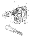
- FIG. 8 It is a perspective view showing the appearance of the striking operation machine which is one embodiment. It is the partially notched front view of FIG. It is a perspective view which shows the external appearance of the striking operation machine in the state which removed the sub handle. It is a longitudinal cross-sectional view of FIG. It is an expanded sectional view which shows a part of FIG. It is a disassembled perspective view of the striking working machine shown by FIG. It is a perspective view which shows a 1st cover and a 2nd cover. It is a perspective view which shows a cylinder case and a fastening member. (A) is an enlarged perspective view of the 9A portion of FIG. 8, (B) is an enlarged perspective view of the 9B portion of FIG.
- the striking working machine 10 has a working machine body 11 and a drive unit 12 disposed below the working machine body 11.
- a handle 13 is provided between the rear end portion of the work implement main body 11 and the rear surface side of the lower end portion of the drive unit 12, and a worker's hand enters between the handle 13 and the drive unit 12.
- Space 14 is provided.
- a sub handle 15 is detachably mounted on the tip end side of the working machine main body 11.
- the striking work machine 10 is a hammer, and can be used to apply a striking force to a work object such as concrete with a tip tool to perform a crushing process or a hatching process of the work object.
- the worker can perform the striking work by holding the handle 13 with one hand at the time of striking work and the sub handle 15 at the other hand. Further, as shown in FIG. 3, the sub-handle 15 is removed from the striking working machine 10, and the handle 13 is gripped with one hand, and the tip side portion of the working machine main body 11 is grasped with the other hand for striking work You can also do
- the work implement body 11 has a cylinder case 16 as shown in FIGS. 4 and 5, and the cylinder case 16 is made of metal.
- a drive unit case 17 is attached to a rear end portion of the cylinder case 16, and the drive unit case 17 faces in a direction substantially perpendicular to the cylinder case 16, and constitutes a drive unit 12.
- the cylinder case 16 is, as shown in FIGS. 5 and 6, located at a cylindrical portion 16a having a substantially circular cross section perpendicular to the direction of the axis A, and at one end side of the cylindrical portion 16a, that is, the tip end side and perpendicular to the axial direction. And an end face of the cylindrical portion 16b.
- the width dimension of the upper, lower, left, and right of the rectangular cylindrical portion 16b is larger than the outer diameter of the cylindrical portion 16a, and the rectangular cylindrical portion 16b protrudes outward in the radial direction of the cylindrical portion 16a.
- the cylinder case 16 and the drive unit case 17 connected to the cylinder case 16 constitute a case assembly 18 for accommodating the respective members constituting the striking working machine 10.
- a second hammer or an intermediate member 19 is disposed in the tip end portion of the cylinder case 16 so as to be capable of reciprocating in the axial direction.
- the end tool T is attached to the attachment hole 19 a of the intermediate member 19, protrudes forward of the cylinder case 16, and applies an impact force to the work object S.
- a tool holder 21 is attached to the tip of the cylinder case 16, and the tool holder 21 guides the reciprocating motion of the tip tool T.
- the tool retainer 21a is rotatably attached to the tool holder 21, and at the time of operation, the tool retainer 21a is directed to a position along the tip tool T, as shown in FIG.
- one end on which the tip tool T is mounted is a front end, and the other end on which the handle 13 is attached is a rear end.
- the side where the working machine main body 11 is provided with respect to the drive unit 12 is the upper side of the striking working machine 10.
- the electric motor 22 as a drive source is accommodated in the drive unit case 17.
- the electric motor 22 includes a rotor 23 and a stator 24 in which the rotor 23 is incorporated.
- the rotary shaft 25 is attached to the rotor 23, the lower end of the rotary shaft 25 is supported by the bearing 26 a, and the bearing 26 a is fixed to the end plate 17 a of the drive case 17.
- the upper end portion of the rotating shaft 25 is supported by a bearing 26 b, and the bearing 26 b is fixed to the support block piece 27.
- the support block piece 27 is attached to the upper end side of the drive unit case 17 and constitutes a part of the drive unit case 17.
- the rotary shaft 25 is rotatable by both bearings 26a, 26b.
- the central axis or axis B of the rotation shaft 25 is substantially perpendicular to the center line or axis A of the cylinder case 16.
- a power cable 28 is attached to the lower end of the handle 13, and the power cable 28 is connected to a commercial power source.
- the handle 13 is provided with a trigger switch 29a which is turned on and off by a trigger 29. When the operator operates the trigger 29 to turn on the trigger switch 29a, electric power is supplied to the electric motor 22 to drive the electric motor 22. Be done. When the trigger switch 29a is turned off, the electric motor 22 is stopped.
- the crankshaft 31 is disposed in parallel to the rotation shaft 25. As shown in FIG. 5, the crankshaft 31 is rotatably supported by a bearing 32 a attached to the support block 27 and a bearing 32 b attached to the cylinder case 16.
- a small gear 33 is provided at the upper end portion of the rotation shaft 25, and the small gear 33 meshes with a large gear 34 attached to the crankshaft 31.
- the small gear 33 and the large gear 34 form a reduction mechanism, and the rotation of the rotation shaft 25 is reduced and transmitted to the crankshaft 31.
- a disc portion 35 is attached to the upper end portion of the crankshaft 31, and a pin 36 is provided at a position eccentric from the rotation center of the disc portion 35.
- a cylindrical cylinder tube 37 is accommodated in the cylinder case 16.
- the cylinder tube 37 is fixed to the cylinder case 16, and a cylinder assembly 38 is formed by the cylinder case 16 and the cylinder tube 37.
- a piston 41 is incorporated inside the cylinder tube 37, and the piston 41 can be reciprocated in the direction of the axis A inside the cylinder tube 37.
- One end of a connecting rod 43 is swingably attached to a pin 42 attached to the piston 41, and the other end of the connecting rod 43 is attached to a pin 36. Therefore, the rotational movement of the rotary shaft 25 of the electric motor 22 is transmitted to the crankshaft 31 decelerated by the reduction mechanism, and the rotational movement of the crankshaft 31 is converted to the reciprocating movement of the piston 41 via the connecting rod 43.
- FIG. 4 shows a state in which the piston 41 has moved to the most distal end side of the cylinder tube 37, that is, a state in which the piston 41 has reached the bottom dead center position.
- the disk portion 35 and the connecting rod 43 constitute the power conversion portion 44 for converting the rotational movement of the rotary shaft 25 into the axial reciprocating movement of the piston 41.
- An accommodating portion 45 is formed at the other end portion of the cylinder case 16, that is, the rear end portion of the cylinder case 16 so as to be positioned above the driving portion case 17, and the power conversion portion 44 is disposed in the accommodating portion 45.
- the cylinder case 16 is provided with an opening 46, and the housing 45 is exposed to the outside of the cylinder case 16 through the opening 46.
- a striker or striker 47 is disposed inside the cylinder tube 37, and the striker 47 abuts on the intermediate piece 19.
- the piston 41 and the striker 47 incorporated in the cylinder tube 37 constitute an impact mechanism 48.
- a pressure chamber 51 is formed between the striker 47 and the piston 41.
- a cylindrical space 52 is formed between the cylinder tube 37 and the cylinder case 16, and the space 52 is in communication with the outside of the striking work machine 10.
- a communication hole 53 for communicating the pressure chamber 51 with the space 52 is formed in the cylinder tube 37.
- the communication hole 53 is located closer to the tip end of the cylinder tube 37 than the O-ring 41a of the piston 41 even when the piston 41 is at the bottom dead center position. Also in the position, the pressure chamber 51 and the space 52 are communicated.
- a cylindrical sleeve 54 is mounted so as to be capable of reciprocating in the axial direction.
- a compression coil spring 55 is mounted in the space 52 so as to be positioned on the rear end side of the sleeve 54.
- the compression coil spring 55 biases the sleeve 54 in a spring force in the direction toward the tip of the cylinder tube 37.
- the cylinder tube 37 is provided with a breathing hole 56 communicating the pressure chamber 51 with the space 52 at a position closer to the tip end of the cylinder tube 37 than the communication hole 53. As shown in FIG. 5, when the sleeve 54 is in the retracted position, the breathing hole 56 is closed by the sleeve 54. Thus, the communication between the pressure chamber 51 and the space 52 is blocked via the breathing hole 56.
- the sleeve 54 is axially driven in conjunction with the axial movement of the intermediate 19.
- the sleeve 54 is driven to a position closing the breathing hole 56, as shown in FIG.
- the electric motor 22 drives the piston 41 from the bottom dead center position toward the top dead center position shown in FIG. 5 toward the rear end of the cylinder tube 37. Be done.
- air is introduced from the space 52 into the pressure chamber 51 via the communication hole 53.
- a plurality of breathing holes 56 are provided at the same cross-sectional position of the cylinder tube 37, and the total communication area is set larger than the communication area of the communication hole 53.
- the intermediate element 19 moves to the tip portion side of the cylinder case 16.
- the sleeve 54 is driven to the tip end side of the cylinder tube 37, and the blocking of the breathing hole 56 is released by the sleeve 54.
- the pressure chamber 51 and the space 52 are in communication with each other through the breathing hole 56, and even if the piston 41 is driven, only air flows between the pressure chamber 51 and the space 52, and the intermediate 19 is driven. Without being carried out, the blanking by the striking working machine 10 is prevented.
- the outer periphery of the cylinder case 16 is covered by a cylinder cover 60 as shown in FIGS. 1 to 3.
- the cylinder cover 60 has an upper cover 61 as a first cover and a lower cover 71 as a second cover, as shown in FIGS. 6 and 7.
- the upper cover 61 and the lower cover 71 can be separated from each other in a direction perpendicular to the axial direction of the cylinder case 16. As illustrated, the two covers 61 and 71 are vertically separable.
- the upper cover 61 and the lower cover 71 are made of resin such as nylon, and have lower thermal conductivity than the metal cylinder case 16 and have heat insulating properties.
- the material of the upper cover 61 and the lower cover 71 is not limited to resin but rubber or the like may be used as long as it is made of a heat insulating material having thermal conductivity lower than that of metal and having heat insulating properties.
- the upper cover 61 is fixed to an arc-shaped portion 62 facing the outer peripheral surface of the cylindrical portion 16 a of the cylinder case 16 and covering the upper side of the cylindrical portion 16 a, and fixed to the rectangular cylindrical portion 16 b of the cylinder case 16 to cover the rectangular cylindrical portion 16 b
- the fixed end portion 63 is integrated with one end side of the arc-shaped portion 62, that is, the tip end side.
- a closing portion 64 is provided on the other end side of the upper cover 61, that is, the rear end side, and the closing portion 64 closes the opening 46 as shown in FIG.
- an extension portion 65 which covers the left and right of the upper end portion of the drive portion case 17 is provided as a first extension portion.
- Each extension portion 65 is continuous with the left and right of the closing portion 64 and covers a portion on the upper end portion side of the drive portion case 17.
- mounting holes 66 are provided in the closed portion 64, and screw holes 66 a are provided in the cylinder case 16 corresponding to the mounting holes 66.
- the upper cover 61 is detachably attached to the cylinder case 16 at the portion of the closed portion 64 by the screw members 67 which are screwed to the screw holes 66 a through the respective attachment holes 66.
- the lower cover 71 is fixed to an arc-shaped portion 72 facing the outer peripheral surface of the cylindrical portion 16a of the cylinder case 16 and covering the lower side of the cylindrical portion 16a, and fixed to the rectangular cylindrical portion 16b of the cylinder case 16 to cover the rectangular cylindrical portion 16b.
- the fixed end 73 is integrated with one end side of the arc-shaped portion 72, that is, the tip end side.
- an extension 74 covering the front of the drive unit case 17 is provided as a second extension.
- the extension portion 74 covers the upper end portion of the front of the drive unit case 17.
- a screw hole 75 is formed in the support block piece 27 and a mounting hole 75a is formed in the extension portion 74 corresponding to the screw hole 75.
- the lower cover 71 is detachably attached to the drive portion case 17 at the extension portion 74 by a screw member 76 which penetrates the attachment hole 75 a and is screwed to the screw hole 75.
- the lower end of the arc-shaped portion 62 of the upper cover 61 abuts against the upper end of the arc-shaped portion 72 of the lower cover 71, and the front end face of the extension 65 Is abutted against the rear end face of the extension 74.
- the upper cover 61 is provided with a fitting protrusion 68
- the lower cover 71 is provided with a fitting groove 77 in which the fitting protrusion 68 is fitted.
- the fitting protrusion 68 and the fitting groove 77 are fitted and connected. As a result, the cylinder cover 60 is not deformed at the time of use, and the upper cover 61 and the lower cover 71 are prevented from coming off carelessly.
- the tip end portion of the upper cover 61 and the tip end side, ie, one end side, of the lower cover 71 are engaged with the tip cover 81 as a fastening member, and the upper cover 61 and the lower cover 71 are fixed to the cylinder case 16 with restricted separation. Ru.
- the tip end cover 81 has an angular ring shape corresponding to the square cylinder portion 16 b of the cylinder case 16 as shown in FIGS. 6 and 8. Similar to the upper cover 61 and the lower cover 71, the tip cover 81 is made of a heat insulating material having a thermal conductivity smaller than that of a metal material, and a resin material such as nylon is used.
- the outer peripheral surface 82 of the tip of the fixed end 63, 73 of the upper cover 61 and the lower cover 71 is inclined inward toward the tip.
- a overlapping portion 83 engaged with the upper cover 61 and the lower cover 71 is provided at the rear end portion of the front end cover 81 so as to cover the outer surface of the outer peripheral surface 82. Therefore, the separable upper cover 61 and the lower cover 71 are fixed in a state of covering the cylinder case 16 by the tip cover 81 engaging with the end of the upper cover 61 and the lower cover 71.
- the cylinder case 16 is covered by the cylinder cover 60 made of a heat insulating material, even if the cylinder case 16 is heated, the cylinder cover 60 is prevented from becoming hot due to the heat. That is, when the piston 41 and the striker 47 reciprocate and the pressure chamber 51 is pressurized, the metal cylinder tube 37 is heated, and the heat is transmitted to the metal cylinder case 16. For this reason, when the striking work machine 10 is used, the temperature of the cylinder case 16 becomes high, but since the cylinder case 16 is covered by the cylinder cover 60, the operator does not touch the cylinder case 16 The workability of the work machine 10 can be improved.
- the striking working machine 10 may be used with the sub handle 15 removed from the working machine main body 11. In that case, when the worker operates the impact working machine 10, one hand holds the cylinder cover 60, but since the cylinder cover 60 does not have a high temperature, even in such a usage form, The workability of the striking work machine 10 can be improved.
- the upper cover 61 and the lower cover 71 are fixed at one end side by the front end cover 81 and therefore do not shift relative to the cylinder case 16. Therefore, even if the operation is performed by gripping the cylinder cover 60, the operator can perform the operation smoothly without the cylinder cover 60 being displaced. Moreover, since the closed portion 64 of the upper cover 61 is fastened to the cylinder case 16 by the screw member 67 and the extension 74 of the lower cover 71 is fastened to the support block piece 27 by the screw member 76, the upper cover 61 and the lower cover The other end side of 71 is fastened, and the shift movement with respect to these cylinder cases 16 is prevented more reliably.
- the upper cover 61 is removed from the cylinder case 16 at the time of maintenance for inspecting the power conversion unit 44 or replenishing the lubricating oil. At this time, the screw member 67 is removed from the cylinder case 16 and the upper cover 61 is moved to the rear of the striking work machine 10. Thus, the upper cover 61 can be easily separated from the lower cover 71, and the power conversion unit 44 is exposed to the outside through the opening 46. Thus, maintenance work can be easily performed.
- an engagement recess 84 is provided on the side surface of the square tube portion 16 b of the cylinder case 16.
- FIGS. 6 and 8 show the whole of the two engagement recesses 84 provided on one side surface of the rectangular tube portion 16b.
- two engagement recesses 84 are provided on the other side surface of the rectangular tube portion 16b, and a portion thereof is shown.
- the distal end cover 81 is provided with an engagement convex portion 85 which engages with an engagement concave portion 84 provided on the other side surface of the rectangular tube portion 16b.
- the distal end cover 81 is provided with an engagement convex portion 85 opposed to the engagement convex portion 85 shown in FIG. 8.
- screw holes 86 are provided at the four corners of the square tube portion 16 b of the cylinder case 16 as shown in FIGS. 6 and 8.
- the flange 87 of the tool holder 21 is provided with a mounting hole 86a corresponding to the screw hole 86, and the tool holder 21 is a cylinder case by a screw member 88 screwed to the screw hole 86 through the mounting hole 86a. Attached to the 16th.
- a bottom cover 89 is attached to the bottom of the drive unit case 17, and the bottom cover 89 is also formed of a heat insulating material.
- a cooling air passage 91 is formed between the cylinder case 16 and the cylinder cover 60.
- a cooling fan 92 is attached to the rotating shaft 25, and the cooling fan 92 is disposed between the support block 27 and the electric motor 22.
- the drive case 17 is provided with a not-shown air guide, and the cooling air generated by the cooling fan 92 is introduced into the drive case 17.
- the introduced cooling air flows along the electric motor 22 to cool the electric motor 22.
- the cooling air flows into the power conversion unit 44 and the cooling air passage 91, and the cooling air that has flowed in is discharged to the outside from the air vent 93 provided in the cylinder cover 60 as shown in FIGS. 6 and 7. Ru.
- the cylinder case 16 and the cylinder tube 37 are cooled by the cooling air flowing outside the cylinder case 16, and the heat transfer from the cylinder case 16 to the cylinder cover 60 is further suppressed.
- the cylinder case 16 has a plurality of projections 94 extending in the axial direction on the outer peripheral surface of the cylindrical portion 16a, as shown in FIG. A protrusion 95 is provided.
- the present invention is not limited to the above embodiment, and various modifications can be made without departing from the scope of the invention.
- the upper cover 61 as the first cover and the lower cover 71 as the second cover are vertically divided into two, but may be horizontally divided into two.
Landscapes
- Engineering & Computer Science (AREA)
- Mechanical Engineering (AREA)
- Percussive Tools And Related Accessories (AREA)
Abstract
容易に着脱することができるとともに、不用意のずれや脱落を抑制したシリンダカバーを有し、作業性に優れた打撃作業機を提供する。打撃作業機(10)は、先端工具を打撃する打撃機構が組み込まれるシリンダチューブを収容するシリンダケース(16)と、シリンダケース(16)の外周を覆う断熱材料製のシリンダカバー(60)とを備えている。シリンダカバー(60)は、シリンダケース(16)の軸線方向に対して垂直な方向に互いに分離可能な第1のカバーである上部カバー(61)と第2のカバーである下部カバー(71)と、これらに係合し、第1のカバーと第2のカバーとをシリンダケース(16)に固定する留め部材としての先端カバー(81)とを有している。
Description
本発明は、先端工具により作業対象物に打撃力を加えて作業対象物を処理する打撃作業機に関する。
打撃作業機には、ハンマやハンマドリル等がある。ハンマは、コンクリート等の作業対象物に先端工具により打撃力を加えて作業対象物の破砕処理作業やハツリ処理作業等を行うために使用される。ハンマドリルは、先端工具により作業対象物に打撃力を加えながら穴あけ作業等を行うために使用される。
このような打撃作業機は、先端工具に打撃力を加えるストライカーつまり打撃子と、空気圧を介して打撃子を駆動するピストンとを有し、打撃子とピストンは金属製のシリンダチューブに組み込まれている。シリンダチューブは金属製のシリンダケースに収容され、シリンダケースの先端部には先端工具が装着される。シリンダケースの後端部には、これに対して略直角方向となってモータケースが連結される。モータケースには、ピストンを往復動するための電動モータが収容される。電動モータの回転軸の回転運動を減速してピストンの直線往復動に変換するために、シリンダケースとモータケースとの間には動力変換部が設けられている。
シリンダケースが外部に露出されていると、温度変化の大きい金属部材に作業者が触れる可能性があり、作業者が不快に感じて操作性が悪くなるという課題がある。打撃作業機には、その後端部にハンドル部が設けられ、先端側にはサブハンドルが設けられている。したがって、作業対象部に種々の処理作業を行うときには、通常では、シリンダケースを把持することはないが、作業対象物や処理作業によっては、シリンダケースの部分を把持して作業を行いたいという要望がある。
このため、シリンダケースの外周にゴム等の弾性部材からなるシリンダカバーを設けた電気ハンマが特許文献1に記載されている。
特許文献1に記載される電気ハンマにおいては、弾性部材からなるシリンダカバーをシリンダケースに巻き付けるようにして装着し、巻付け端の割り部を面ファスナーにより固定するようにしている。面ファスナーを用いると、シリンダカバーの着脱を容易に行うことができるが、作業中にシリンダカバーがシリンダケースに対してずれることがあり、作業者はシリンダカバーを把持しにくくなったりする。さらには、シリンダカバーが剥がれてしまったりするという問題が生じることがあり、打撃作業機の作業性が悪いという課題がある。
面ファスナーを用いてシリンダカバーを固定するとなく、円筒形状のシリンダカバーをシリンダケースの先端部から滑らせるようにして被せるようにすることも可能であるが、使用者は容易にシリンダカバーを着脱することが困難になる。打撃作業機においては、動力変換部を点検したり、潤滑油を補充したりするために、メンテナンスが行われるが、シリンダカバーの着脱が困難になると、メンテナンスの作業性が悪くなる。さらに、円筒形状のシリンダカバーをシリンダケースに被せるには、シリンダケースの形状が限定されてしまうという課題がある。
本発明の目的は、容易に着脱することができるとともに、不用意のずれや脱落を抑制したシリンダカバーを有し、作業性に優れた打撃作業機を提供することにある。
本発明の打撃作業機は、先端工具を打撃する打撃機構が組み込まれる円筒状のシリンダチューブと、前記シリンダチューブを収容するシリンダケースと、前記シリンダケースの外周を覆う断熱材料製のシリンダカバーと、を備え、前記シリンダカバーは、前記シリンダチューブの軸線方向に対して垂直な方向に互いに分離可能な第1のカバーおよび第2のカバーと、前記第1のカバーと前記第2のカバーの前記軸線方向の端部に係合し、前記第1のカバーと前記第2のカバーとの前記軸線方向に対して垂直な方向への分離を規制する留め部材と、を有する。
打撃作業機のシリンダケースは断熱材製のシリンダカバーにより覆われるので、シリンダケースが発熱しても、作業者がシリンダケースに直接触れることがない。シリンダカバーは加熱されることがないので、作業者がシリンダカバーを把持して打撃作業を行っても、容易に作業を行うことができ、打撃作業の操作性を向上させることができる。
シリンダカバーは第1と第2の分離可能なカバーにより形成されており、第1のカバーと第2のカバーの端部は、留め部材により分離が規制される。これにより、シリンダカバーをシリンダケースの外側に容易に装着することができ、作業中にシリンダカバーがシリンダケースに対してずれることがなく、打撃作業機の作業性を向上することができる。
以下、本発明の実施の形態を図面に基づいて詳細に説明する。打撃作業機10は、図1および図2に示されるように、作業機本体11とこの作業機本体11の下側に配置される駆動部12とを有している。作業機本体11の後端部と駆動部12の下端部の背面側との間には、ハンドル13が設けられ、ハンドル13と駆動部12との間には、作業者の手が入り込む作業用の空間14が設けられている。作業機本体11の先端側には、サブハンドル15が着脱自在に装着されている。
打撃作業機10はハンマであり、コンクリート等の作業対象物に先端工具により打撃力を加えて作業対象物の破砕処理やハツリ処理を行うために使用することができる。作業者は、打撃作業時に、一方の手でハンドル13を把持し、他方の他でサブハンドル15を把持して、打撃作業を行うことができる。また、図3に示されるように、サブハンドル15を打撃作業機10から取り外して、一方の手でハンドル13を把持し、他方の手で作業機本体11の先端側部を把持して打撃作業を行うこともできる。
作業機本体11は、図4および図5に示されるように、シリンダケース16を有しており、シリンダケース16は金属製である。シリンダケース16の後端部には駆動部ケース17が取り付けられ、駆動部ケース17は、シリンダケース16に対して略直角方向を向いており、駆動部12を構成する。シリンダケース16は、図5および図6に示されるように、軸線A方向に垂直な断面が略円形の円筒部16aと、円筒部16aの一端部側つまり先端部側に位置し軸線方向に垂直な端面が略四角形の角筒部16bとを有している。角筒部16bの上下左右の幅寸法は、円筒部16aの外径よりも大きく、角筒部16bは円筒部16aの径方向外方に突出している。
シリンダケース16とこれに連結される駆動部ケース17とにより、打撃作業機10を構成する各部材を収容するためのケース組立体18が構成される。
シリンダケース16の先端部内には、セカンドハンマつまり中間子19が軸線方向に往復動自在に配置される。図4に示されるように、先端工具Tは、中間子19の取付孔19aに装着されてシリンダケース16の前方に突出し、作業対象物Sに打撃力を加える。シリンダケース16の先端にはツールホルダ21が取り付けられ、ツールホルダ21は先端工具Tの往復動を案内する。ツールリテーナ21aがツールホルダ21に回動自在に装着され、ツールリテーナ21aは、作業時には図4に示されるように、先端工具Tに沿う位置に向けられる。
打撃作業機10の前後、上下については、図1~図4に示されるように、先端工具Tが装着される一端部を先端部とし、ハンドル13が取り付けられる他端部を後端部とし、駆動部12に対して作業機本体11が設けられる側を打撃作業機10の上側とする。
駆動部ケース17内には、駆動源としての電動モータ22が収容され、電動モータ22はロータ23と、ロータ23が組み込まれるステータ24とを備えている。図5に示されるように、ロータ23には回転軸25が取り付けられ、回転軸25の下端部は軸受26aに支持され、軸受26aは駆動部ケース17の端板17aに固定されている。回転軸25の上端部は軸受26bに支持され、軸受26bは支持ブロック片27に固定されている。支持ブロック片27は駆動部ケース17の上端側に取り付けられて、駆動部ケース17の一部を構成する。回転軸25は両方の軸受26a、26bにより回転自在である。回転軸25の中心軸つまり軸線Bは、シリンダケース16の中心線つまり軸線Aに対して略垂直方向となっている。
ハンドル13の下端部には電源ケーブル28が取り付けられており、電源ケーブル28は、商用電源に接続される。ハンドル13にはトリガ29によりオンオフ操作されるトリガスイッチ29aが設けられており、作業者がトリガ29を操作してトリガスイッチ29aがオンすると、電力が電動モータ22に供給されて電動モータ22が駆動される。トリガスイッチ29aがオフされると、電動モータ22は停止する。
回転軸25に平行となってクランク軸31が配置されている。図5に示されるように、クランク軸31は支持ブロック片27に装着された軸受32aと、シリンダケース16に装着された軸受32bとにより支持されて回転自在である。回転軸25の上端部には小歯車33が設けられ、小歯車33はクランク軸31に取り付けられた大歯車34に噛み合っている。小歯車33と大歯車34は減速機構を形成しており、回転軸25の回転は減速されてクランク軸31に伝達される。クランク軸31の上端部に円板部35が取り付けられており、円板部35の回転中心から偏心した位置にピン36が設けられている。
図5に示されるように、シリンダケース16の内部には円筒状のシリンダチューブ37が収容されている。シリンダチューブ37はシリンダケース16に固定され、シリンダケース16とシリンダチューブ37とによりシリンダ組立体38が形成される。
シリンダチューブ37の内部にピストン41が組み込まれ、ピストン41はシリンダチューブ37の内部で軸線Aの方向に往復動可能である。ピストン41に取り付けられたピン42にはコンロッド43の一端部が揺動自在に装着され、コンロッド43の他端部はピン36に装着されている。したがって、電動モータ22の回転軸25の回転運動は、減速機構により減速されたクランク軸31に伝達され、クランク軸31の回転運動はコンロッド43を介してピストン41の往復動に変換される。図4においては、ピストン41がシリンダチューブ37の最も先端側に移動した状態、つまりピストン41が下死点の位置となった状態を示す。
このように、円板部35とコンロッド43は、回転軸25の回転運動をピストン41の軸線方向の往復運動に変換するための動力変換部44を構成する。シリンダケース16の他端部つまり後端部には、駆動部ケース17の上方に位置させて収容部45が形成されており、動力変換部44は収容部45内に配置されている。シリンダケース16には開口部46が設けられ、収容部45は開口部46を介してシリンダケース16の外部に露出される。
シリンダチューブ37の内部にストライカーつまり打撃子47が配置され、打撃子47は中間子19に当接する。シリンダチューブ37内に組み込まれるピストン41、打撃子47は、打撃機構48を構成する。打撃子47とピストン41の間に圧力室51が形成されている。シリンダチューブ37とシリンダケース16との間には、円筒形状の空間52が形成されており、空間52は打撃作業機10の外部に連通されている。シリンダチューブ37には、圧力室51と空間52とを連通させる連通孔53が形成されている。連通孔53は、ピストン41が下死点の位置となった状態のもとでも、ピストン41のOリング41aよりもシリンダチューブ37の先端側に位置しており、連通孔53はピストン41がどの位置においても、圧力室51と空間52とを連通させる。
円筒状の空間52には、円筒形状のスリーブ54が軸方向に往復動自在に装着されている。スリーブ54の後端部側に位置させて空間52には圧縮コイルばね55が装着されている。圧縮コイルばね55はスリーブ54に対してシリンダチューブ37の先端部に向かう方向のばね力を付勢する。シリンダチューブ37には、圧力室51と空間52とを連通させる呼吸孔56が連通孔53よりもシリンダチューブ37の先端部側に位置させて設けられている。図5に示されるように、スリーブ54が後退限位置となると、呼吸孔56はスリーブ54により閉じられる。これにより、呼吸孔56を介して圧力室51と空間52との連通が遮断される。
スリーブ54は、中間子19の軸方向移動に連動して軸方向に駆動される。作業者が打撃作業機10を操作して先端工具Tが作業対象物Sに突き当てられると、図5に示されるように、スリーブ54は呼吸孔56を閉じる位置に駆動される。この状態のもとで、トリガ29が操作されると、電動モータ22によりピストン41は図5に示される下死点位置から上死点位置に向けてシリンダチューブ37の後端部に向けて駆動される。このときには、連通孔53を介して空間52から圧力室51内に空気が導入される。呼吸孔56は、シリンダチューブ37の同一断面位置に複数個設けられており、合計の連通面積は、連通孔53の連通面積よりも大きく設定されている。
電動モータ22によりピストン41がシリンダチューブ37の先端部、つまり下死点の位置に向けて駆動されると、圧力室51の圧力が上昇して打撃子47が駆動される。これにより、打撃子47の打撃力は中間子19を介して先端工具Tに伝達され、中間子19に装着された先端工具Tにより作業対象物Sの破砕処理等が行われる。ピストン41が下死点に向けて駆動されるときには、連通孔53を介して圧力室51の空気が一部漏出するが、連通面積が小さく設定されているので、漏出する空気は僅かである。
破砕処理等が終了し、先端工具Tが作業対象物Sから離されると、中間子19がシリンダケース16の先端部側に移動する。これに連動してスリーブ54がシリンダチューブ37の先端部側に駆動され、スリーブ54により呼吸孔56の閉塞が解除される。これにより、呼吸孔56を介して圧力室51と空間52とが連通状態となり、ピストン41が駆動されても、圧力室51と空間52との間で空気が流れるのみであり、中間子19は駆動されずに、打撃作業機10による空打ちが防止される。
シリンダケース16の外周は、図1~図3に示されるように、シリンダカバー60により覆われる。シリンダカバー60は、図6および図7に示されるように、第1のカバーとしての上部カバー61と、第2のカバーとしての下部カバー71とを有している。上部カバー61と下部カバー71は、シリンダケース16の軸線方向に対して垂直な方向に互いに分離可能である。図示するように、2つのカバー61、71は上下に分離可能となっている。上部カバー61と下部カバー71は、ナイロン等からなる樹脂製であり、金属製のシリンダケース16よりも熱伝導率が低く、断熱特性を有している。上部カバー61と下部カバー71の材料としては、金属よりも熱伝導率が低く、断熱特性を有する断熱材料製であれば、樹脂に限られずゴム等を用いても良い。
上部カバー61は、シリンダケース16の円筒部16aの外周面に対向して円筒部16aの上側を覆う円弧状部62と、シリンダケース16の角筒部16bに固定され角筒部16bを覆う固定端部63とを有し、固定端部63は円弧状部62の一端部側つまり先端部側に一体となっている。
上部カバー61の他端部側つまり後端部側には、閉塞部64が設けられており、閉塞部64は、図5に示されるように、開口部46を閉じる。上部カバー61の閉塞部64には、駆動部ケース17の上端部の左右を覆う延長部65が第1の延長部として設けられている。それぞれの延長部65は、閉塞部64の左右に連なっており、駆動部ケース17の上端部側の部分を覆う。
閉塞部64には4つの取付孔66が設けられており、取付孔66に対応してシリンダケース16にはねじ孔66aが設けられている。それぞれの取付孔66を貫通してねじ孔66aにねじ結合されるねじ部材67により、上部カバー61は閉塞部64の部分でシリンダケース16に着脱自在に取り付けられる。
下部カバー71は、シリンダケース16の円筒部16aの外周面に対向して円筒部16aの下側を覆う円弧状部72と、シリンダケース16の角筒部16bに固定され角筒部16bを覆う固定端部73とを有し、固定端部73は円弧状部72の一端部側つまり先端部側に一体となっている。下部カバー71の後端部には、駆動部ケース17の正面を覆う延長部74が第2の延長部として設けられている。延長部74は駆動部ケース17の正面の上端部分を覆う。図5および図6に示されるように、支持ブロック片27にねじ孔75が形成され、ねじ孔75に対応させて延長部74に取付孔75aが形成されている。取付孔75aを貫通してねじ孔75にねじ結合されるねじ部材76により、下部カバー71は延長部74の部分で駆動部ケース17に着脱自在に取り付けられる。
上部カバー61と下部カバー71とをシリンダケース16に取り付けると、上部カバー61の円弧状部62の下端部は下部カバー71の円弧状部72の上端部に突き当てられ、延長部65の前端面は延長部74の後端面に突き当てられる。上部カバー61には嵌合突起68が設けられ、下部カバー71には嵌合突起68が嵌合する嵌合溝77が設けられている。上部カバー61と下部カバー71とが突き当てられる部分は、嵌合突起68と嵌合溝77とが嵌合して連なった状態となる。これにより、シリンダカバー60は使用時に変形することなく、不用意に上部カバー61と下部カバー71とが外れることがない。
上部カバー61の先端部と下部カバー71の先端側つまり一端側は、留め部材としての先端カバー81に係合し、上部カバー61と下部カバー71は、分離が規制されてシリンダケース16に固定される。先端カバー81は、図6および図8に示されるように、シリンダケース16の角筒部16bに対応した角環形状である。先端カバー81は、上部カバー61と下部カバー71と同様に、金属材料よりも熱伝導率が小さい断熱材料製であり、ナイロンなどの樹脂材料が用いられている。
上部カバー61と下部カバー71の固定端部63、73の先端部の外周面82は、先端に向けて内側に傾斜している。一方、先端カバー81の後端部には、外周面82の外面を覆うように上部カバー61と下部カバー71とに係合する重合部83が設けられている。したがって、分離可能な上部カバー61と下部カバー71は、先端カバー81が上部カバー61と下部カバー71の端部に係合することによって、シリンダケース16を覆った状態で固定される。シリンダケース16は、断熱材料製のシリンダカバー60により覆われているので、シリンダケース16が加熱しても、その熱によってシリンダカバー60が高温となることが防止される。つまり、ピストン41、打撃子47が往復動し、圧力室51が加圧されると、金属製のシリンダチューブ37が加熱され、その熱は金属製のシリンダケース16に伝達される。このため、打撃作業機10が使用されると、シリンダケース16の温度が高くなるが、シリンダケース16はシリンダカバー60により覆われているので、作業者がシリンダケース16に触れることはなく、打撃作業機10の作業性を高めることができる。
図3に示されるように、打撃作業機10は、サブハンドル15を作業機本体11から取り外した状態で使用されることがある。その場合には、作業者が打撃作業機10を操作するときには、片方の手でシリンダカバー60を把持することになるが、シリンダカバー60は高温にはならないので、そのような使用形態においても、打撃作業機10の作業性を高めることができる。
上部カバー61と下部カバー71は、先端カバー81により一端側が固定されているので、シリンダケース16に対してずれ移動することがない。したがって、シリンダカバー60を把持して作業を行っても、シリンダカバー60がずれることなく、作業者は円滑に作業を行うことができる。しかも、上部カバー61の閉塞部64はねじ部材67によりシリンダケース16に締結され、下部カバー71の延長部74はねじ部材76により支持ブロック片27に締結されているので、上部カバー61と下部カバー71の他端側は締結され、これらのシリンダケース16に対するずれ移動は、より確実に防止される。
動力変換部44を点検したり、潤滑油を補充したりするメンテナンス時には、上部カバー61がシリンダケース16から取り外される。このときには、ねじ部材67をシリンダケース16から取り外し、上部カバー61を打撃作業機10の後方に移動させる。これにより、容易に上部カバー61を下部カバー71から分離させることができるとともに、動力変換部44は開口部46を介して外部に露出される。これにより、メンテナンス作業を容易に行うことができる。
図6および図8に示されるように、シリンダケース16の角筒部16bの側面には、係合凹部84が設けられている。図6および図8には、角筒部16bの一方の側面に設けられた2つの係合凹部84の全体が示されている。角筒部16bの他方の側面にも同様に2つの係合凹部84が設けられており、その一部が示されている。先端カバー81には、角筒部16bの他方の側面に設けられた係合凹部84に係合する係合凸部85が設けられている。同様に、先端カバー81には、図8に示された係合凸部85に対向して係合凸部85が設けられている。したがって、先端カバー81をシリンダケース16の角筒部16bに装着すると、係合凸部85が係合凹部84に係合し、先端カバー81のシリンダケース16に対するずれ移動が防止される。
ツールホルダ21をシリンダケース16の先端面に取り付けるために、図6および図8に示されるように、シリンダケース16の角筒部16bの四隅には、ねじ孔86が設けられている。ツールホルダ21のフランジ87にはねじ孔86に対応させて取付孔86aが設けられており、取付孔86aを貫通してねじ孔86にねじ結合されるねじ部材88により、ツールホルダ21はシリンダケース16に取り付けられる。
ツールホルダ21がシリンダケース16に取り付けられると、フランジ87の内面には係合凸部85の先端面が接触する。これにより、先端カバー81がシリンダケース16からシリンダケース16の前方に外れることが抑制される。駆動部ケース17の底部には、底部カバー89が装着されており、底部カバー89も断熱材料により形成されている。
図5に示されるように、シリンダケース16とシリンダカバー60との間には、冷却風通路91が形成されている。冷却ファン92が回転軸25に取り付けられ、冷却ファン92は支持ブロック片27と電動モータ22との間に配置されている。駆動部ケース17には図示しない導風口が設けられており、冷却ファン92により生成される冷却風が駆動部ケース17の内部に導入される。導入された冷却風は電動モータ22に沿って流れ、電動モータ22を冷却する。さらに、冷却風は動力変換部44と冷却風通路91に流入し、流入した冷却風は、図6および図7に示されるように、シリンダカバー60に設けられた通風口93から外部に排出される。
このように、シリンダケース16の外側を流れる冷却風によってシリンダケース16とシリンダチューブ37が冷却され、さらにシリンダカバー60へのシリンダケース16からの熱伝達が抑制される。
シリンダケース16にはサブハンドル15が装着される部分に対応させて、図8に示されるように、円筒部16aの外周面には軸線方向に延びる複数本の突起部94と、円周方向の突起部95とが設けられている。
本発明は前記実施の形態に限定されるものではなく、その要旨を逸脱しない範囲で種々変更可能である。例えば、第1のカバーとしての上部カバー61と、第2のカバーとしての下部カバー71は、上下に2分割されているが、左右に2分割された形態としても良い。
10…打撃作業機、11…作業機本体、12…駆動部、13…ハンドル、14…空間、15…サブハンドル、16…シリンダケース、16a…円筒部、16b…角筒部、17…駆動部ケース、18…ケース組立体、19…中間子、21…ツールホルダ、22…電動モータ、27…支持ブロック片、29…トリガ、29a…トリガスイッチ、31…クランク軸、33…小歯車、34…大歯車、35…円板部、37…シリンダチューブ、38…シリンダ組立体、41…ピストン、43…コンロッド、44…動力変換部、45…収容部、46…開口部、47…打撃子、48…打撃機構、51…圧力室、52…空間、53…連通孔、54…スリーブ、55…圧縮コイルばね、56…呼吸孔、60…シリンダカバー、61…上部カバー、62…円弧状部、63…固定端部、64…閉塞部、65…延長部、66…取付孔、67…ねじ部材、68…嵌合突起、71…下部カバー、72…円弧状部、73…固定端部、74…延長部、75…ねじ孔、76…ねじ部材、77…嵌合溝、81…先端カバー、82…外周面、83…重合部、84…係合凹部、85…係合凸部、86…ねじ孔、87…フランジ、88…ねじ部材、91…冷却風通路、92…冷却ファン、93…通風口、94…突起部、95…突起部。
Claims (10)
- 先端工具を打撃する打撃機構が組み込まれる円筒状のシリンダチューブと、
前記シリンダチューブを収容するシリンダケースと、
前記シリンダケースの外周を覆う断熱材料製のシリンダカバーと、を備え、
前記シリンダカバーは、
前記シリンダチューブの軸線方向に対して垂直な方向に互いに分離可能な第1のカバーおよび第2のカバーと、
前記第1のカバーと前記第2のカバーの前記軸線方向の端部に係合し、前記第1のカバーと前記第2のカバーとの前記軸線方向に対して垂直な方向への分離を規制する留め部材と、
を有する打撃作業機。 - 前記シリンダケースに連結されてケース組立体を形成し、駆動源を収容する駆動部ケースを有し、
前記第1のカバーと前記第2のカバーは、前記軸線方向の一端側が前記留め部材に係合し、他端側が前記ケース組立体に着脱自在に取り付けられる、請求項1記載の打撃作業機。 - 前記シリンダケースの前記軸線方向の他端側に形成された収容部に配置され、前記駆動源の回転軸の回転運動を前記打撃機構の軸線方向の往復運動に変換する動力変換部を有し、前記シリンダケースは、前記収容部を外部に露出させる開口部を有し、前記第1のカバーは前記開口部を閉じる閉塞部を有する、請求項2記載の打撃作業機。
- 前記第1のカバーは前記駆動部ケースの一部を覆う第1の延長部を有し、前記第2のカバーは前記第1の延長部に連なる第2の延長部を有する、請求項2または3記載の打撃作業機。
- 前記留め部材は、前記シリンダケースに向けて突出する係合凸部を有し、前記シリンダケースは前記係合凸部が係合する係合凹部を有する、請求項1~4のいずれか1項に記載の打撃作業機。
- 前記シリンダケースの一端に固定され、先端工具の移動を案内するツールホルダを有し、前記係合凸部は前記ツールホルダに当接し、前記留め部材が前記シリンダケースから外れるのを抑制する、請求項5記載の打撃作業機。
- 前記回転軸に冷却ファンを装着し、前記シリンダカバーと前記シリンダケースの間に冷却風通路を形成し、前記冷却ファンにより生成される冷却風を、前記冷却風通路を介して外部に排出する、請求項3記載の打撃作業機。
- 前記留め部材は、前記第1のカバーおよび前記第2のカバーの外側を覆うように係合する重合部を有する、請求項1~7のいずれか1項に記載の打撃作業機。
- 前記シリンダケースは、前記軸線方向に垂直な断面が略円形の円筒部と、前記円筒部の一端部側に位置し前記軸線方向に垂直な断面が略四角形の角筒部と、を有し、
前記留め部材は、前記角筒部に対応する略四角形であり、前記シリンダケースの一端部を覆う、請求項1~8のいずれか1項に記載の打撃作業機。 - 前記第1のカバーと前記第2のカバーの一方に嵌合突起を設け、他方に嵌合溝を設け、前記嵌合突起と前記嵌合溝との嵌合により、前記第1のカバーと前記第2のカバーとを分離可能に組み付ける、請求項1~9のいずれか1項に記載の打撃作業機。
Priority Applications (1)
| Application Number | Priority Date | Filing Date | Title |
|---|---|---|---|
| JP2019562890A JP6801798B2 (ja) | 2017-12-28 | 2018-11-30 | 打撃作業機 |
Applications Claiming Priority (2)
| Application Number | Priority Date | Filing Date | Title |
|---|---|---|---|
| JP2017254192 | 2017-12-28 | ||
| JP2017-254192 | 2017-12-28 |
Publications (1)
| Publication Number | Publication Date |
|---|---|
| WO2019130982A1 true WO2019130982A1 (ja) | 2019-07-04 |
Family
ID=67067266
Family Applications (1)
| Application Number | Title | Priority Date | Filing Date |
|---|---|---|---|
| PCT/JP2018/044200 Ceased WO2019130982A1 (ja) | 2017-12-28 | 2018-11-30 | 打撃作業機 |
Country Status (2)
| Country | Link |
|---|---|
| JP (1) | JP6801798B2 (ja) |
| WO (1) | WO2019130982A1 (ja) |
Cited By (4)
| Publication number | Priority date | Publication date | Assignee | Title |
|---|---|---|---|---|
| EP3845341A1 (de) * | 2019-12-19 | 2021-07-07 | Robert Bosch GmbH | Handwerkzeugmaschine mit fingerschutz |
| EP3888851A1 (de) * | 2020-04-03 | 2021-10-06 | Hilti Aktiengesellschaft | Elektrische handwerkzeugmaschine |
| AU2021203133B2 (en) * | 2020-06-02 | 2022-10-06 | Snap-On Incorporated | Housing clamp for a power tool |
| JP2022552813A (ja) * | 2019-10-08 | 2022-12-20 | アトラス・コプコ・インダストリアル・テクニーク・アクチボラグ | 絶縁用工具カバー組立体 |
Citations (10)
| Publication number | Priority date | Publication date | Assignee | Title |
|---|---|---|---|---|
| JPH0486186U (ja) * | 1990-11-30 | 1992-07-27 | ||
| JPH0636787U (ja) * | 1992-10-23 | 1994-05-17 | 日立工機株式会社 | 打撃工具 |
| JP2003522040A (ja) * | 2000-02-10 | 2003-07-22 | ローベルト ボツシユ ゲゼルシヤフト ミツト ベシユレンクテル ハフツング | 手持ち工作機械 |
| JP2005161497A (ja) * | 2003-12-04 | 2005-06-23 | Hitachi Koki Co Ltd | 打撃工具 |
| JP2009050962A (ja) * | 2007-08-27 | 2009-03-12 | Hitachi Koki Co Ltd | 往復動工具 |
| US20120118599A1 (en) * | 2009-05-11 | 2012-05-17 | Robert Bosch Gmbh | Hand-Held Power Tool, in particular Electric Hand-Held Power Tool |
| JP2013075351A (ja) * | 2011-09-30 | 2013-04-25 | Hitachi Koki Co Ltd | 電動工具 |
| JP2014124697A (ja) * | 2012-12-25 | 2014-07-07 | Makita Corp | 打撃工具 |
| JP2015217470A (ja) * | 2014-05-16 | 2015-12-07 | 株式会社マキタ | 打撃工具 |
| JP2017080853A (ja) * | 2015-10-30 | 2017-05-18 | 日立工機株式会社 | 電動工具 |
-
2018
- 2018-11-30 WO PCT/JP2018/044200 patent/WO2019130982A1/ja not_active Ceased
- 2018-11-30 JP JP2019562890A patent/JP6801798B2/ja active Active
Patent Citations (10)
| Publication number | Priority date | Publication date | Assignee | Title |
|---|---|---|---|---|
| JPH0486186U (ja) * | 1990-11-30 | 1992-07-27 | ||
| JPH0636787U (ja) * | 1992-10-23 | 1994-05-17 | 日立工機株式会社 | 打撃工具 |
| JP2003522040A (ja) * | 2000-02-10 | 2003-07-22 | ローベルト ボツシユ ゲゼルシヤフト ミツト ベシユレンクテル ハフツング | 手持ち工作機械 |
| JP2005161497A (ja) * | 2003-12-04 | 2005-06-23 | Hitachi Koki Co Ltd | 打撃工具 |
| JP2009050962A (ja) * | 2007-08-27 | 2009-03-12 | Hitachi Koki Co Ltd | 往復動工具 |
| US20120118599A1 (en) * | 2009-05-11 | 2012-05-17 | Robert Bosch Gmbh | Hand-Held Power Tool, in particular Electric Hand-Held Power Tool |
| JP2013075351A (ja) * | 2011-09-30 | 2013-04-25 | Hitachi Koki Co Ltd | 電動工具 |
| JP2014124697A (ja) * | 2012-12-25 | 2014-07-07 | Makita Corp | 打撃工具 |
| JP2015217470A (ja) * | 2014-05-16 | 2015-12-07 | 株式会社マキタ | 打撃工具 |
| JP2017080853A (ja) * | 2015-10-30 | 2017-05-18 | 日立工機株式会社 | 電動工具 |
Cited By (10)
| Publication number | Priority date | Publication date | Assignee | Title |
|---|---|---|---|---|
| JP2022552813A (ja) * | 2019-10-08 | 2022-12-20 | アトラス・コプコ・インダストリアル・テクニーク・アクチボラグ | 絶縁用工具カバー組立体 |
| JP7617089B2 (ja) | 2019-10-08 | 2025-01-17 | アトラス・コプコ・インダストリアル・テクニーク・アクチボラグ | 絶縁用工具カバー組立体 |
| EP3845341A1 (de) * | 2019-12-19 | 2021-07-07 | Robert Bosch GmbH | Handwerkzeugmaschine mit fingerschutz |
| EP3888851A1 (de) * | 2020-04-03 | 2021-10-06 | Hilti Aktiengesellschaft | Elektrische handwerkzeugmaschine |
| WO2021198023A1 (de) * | 2020-04-03 | 2021-10-07 | Hilti Aktiengesellschaft | Elektrische handwerkzeugmaschine |
| CN115210045A (zh) * | 2020-04-03 | 2022-10-18 | 喜利得股份公司 | 手持式电动动力工具 |
| US12257683B2 (en) * | 2020-04-03 | 2025-03-25 | Hilti Aktiengesellschaft | Electric hand-held power tool |
| AU2021203133B2 (en) * | 2020-06-02 | 2022-10-06 | Snap-On Incorporated | Housing clamp for a power tool |
| US11691261B2 (en) | 2020-06-02 | 2023-07-04 | Snap-On Incorporated | Housing clamp for a power tool |
| US12162131B2 (en) | 2020-06-02 | 2024-12-10 | Snap-On Incorporated | Housing clamp for a power tool |
Also Published As
| Publication number | Publication date |
|---|---|
| JP6801798B2 (ja) | 2020-12-16 |
| JPWO2019130982A1 (ja) | 2020-09-24 |
Similar Documents
| Publication | Publication Date | Title |
|---|---|---|
| JP6334144B2 (ja) | 往復動式作業工具 | |
| US10843321B2 (en) | Power tool | |
| WO2019130982A1 (ja) | 打撃作業機 | |
| US9943940B2 (en) | Power tool | |
| JP6258093B2 (ja) | 打撃工具 | |
| CN104114332B (zh) | 冲击工具 | |
| CN101633163A (zh) | 具有传动转换器的电动工具 | |
| EP3213876B1 (en) | Striking device | |
| CN100415453C (zh) | 锤钻 | |
| JP2017144507A (ja) | 集塵装置および作業工具 | |
| JP6116058B2 (ja) | 作業工具 | |
| US20210146520A1 (en) | Piston | |
| JP7251612B2 (ja) | 打撃作業機 | |
| US20230390911A1 (en) | Universal Chisel Attachment | |
| CN211758686U (zh) | 击打工具 | |
| JP6348337B2 (ja) | 往復動式作業工具 | |
| US12246426B2 (en) | Rotary hammer | |
| JP2015047661A (ja) | 打撃工具 | |
| JP2012171063A (ja) | 打撃工具 | |
| US20250058446A1 (en) | Transverse axis rotary hammer | |
| JP5794191B2 (ja) | 打撃工具 | |
| JP2024030739A (ja) | 打撃工具 | |
| JP5857851B2 (ja) | 打撃工具 | |
| JP5783119B2 (ja) | 打撃工具 | |
| JP2025004946A (ja) | 往復動工具 |
Legal Events
| Date | Code | Title | Description |
|---|---|---|---|
| 121 | Ep: the epo has been informed by wipo that ep was designated in this application |
Ref document number: 18895555 Country of ref document: EP Kind code of ref document: A1 |
|
| ENP | Entry into the national phase |
Ref document number: 2019562890 Country of ref document: JP Kind code of ref document: A |
|
| NENP | Non-entry into the national phase |
Ref country code: DE |
|
| 122 | Ep: pct application non-entry in european phase |
Ref document number: 18895555 Country of ref document: EP Kind code of ref document: A1 |