WO2019130686A1 - 含油排水処理用濾過膜及び含油排水処理用濾過モジュール - Google Patents
含油排水処理用濾過膜及び含油排水処理用濾過モジュール Download PDFInfo
- Publication number
- WO2019130686A1 WO2019130686A1 PCT/JP2018/035038 JP2018035038W WO2019130686A1 WO 2019130686 A1 WO2019130686 A1 WO 2019130686A1 JP 2018035038 W JP2018035038 W JP 2018035038W WO 2019130686 A1 WO2019130686 A1 WO 2019130686A1
- Authority
- WO
- WIPO (PCT)
- Prior art keywords
- filtration
- oil
- layer
- structural unit
- group
- Prior art date
- Legal status (The legal status is an assumption and is not a legal conclusion. Google has not performed a legal analysis and makes no representation as to the accuracy of the status listed.)
- Ceased
Links
Images


Classifications
-
- B—PERFORMING OPERATIONS; TRANSPORTING
- B01—PHYSICAL OR CHEMICAL PROCESSES OR APPARATUS IN GENERAL
- B01D—SEPARATION
- B01D63/00—Apparatus in general for separation processes using semi-permeable membranes
- B01D63/02—Hollow fibre modules
-
- B—PERFORMING OPERATIONS; TRANSPORTING
- B01—PHYSICAL OR CHEMICAL PROCESSES OR APPARATUS IN GENERAL
- B01D—SEPARATION
- B01D17/00—Separation of liquids, not provided for elsewhere, e.g. by thermal diffusion
-
- B—PERFORMING OPERATIONS; TRANSPORTING
- B01—PHYSICAL OR CHEMICAL PROCESSES OR APPARATUS IN GENERAL
- B01D—SEPARATION
- B01D69/00—Semi-permeable membranes for separation processes or apparatus characterised by their form, structure or properties; Manufacturing processes specially adapted therefor
- B01D69/02—Semi-permeable membranes for separation processes or apparatus characterised by their form, structure or properties; Manufacturing processes specially adapted therefor characterised by their properties
-
- B—PERFORMING OPERATIONS; TRANSPORTING
- B01—PHYSICAL OR CHEMICAL PROCESSES OR APPARATUS IN GENERAL
- B01D—SEPARATION
- B01D69/00—Semi-permeable membranes for separation processes or apparatus characterised by their form, structure or properties; Manufacturing processes specially adapted therefor
- B01D69/08—Hollow fibre membranes
-
- B—PERFORMING OPERATIONS; TRANSPORTING
- B01—PHYSICAL OR CHEMICAL PROCESSES OR APPARATUS IN GENERAL
- B01D—SEPARATION
- B01D71/00—Semi-permeable membranes for separation processes or apparatus characterised by the material; Manufacturing processes specially adapted therefor
- B01D71/06—Organic material
- B01D71/30—Polyalkenyl halides
- B01D71/32—Polyalkenyl halides containing fluorine atoms
- B01D71/36—Polytetrafluoroethylene
-
- C—CHEMISTRY; METALLURGY
- C02—TREATMENT OF WATER, WASTE WATER, SEWAGE, OR SLUDGE
- C02F—TREATMENT OF WATER, WASTE WATER, SEWAGE, OR SLUDGE
- C02F1/00—Treatment of water, waste water, or sewage
- C02F1/44—Treatment of water, waste water, or sewage by dialysis, osmosis or reverse osmosis
Definitions
- the present disclosure relates to a filtration membrane for oil-containing wastewater treatment and a filtration module for oil-containing wastewater treatment.
- a filtration membrane is used to remove oil from oil-containing wastewater.
- This filtration membrane performs a filtration process by allowing other than these impurities to permeate while preventing permeation of oil and other impurities contained in oil-containing wastewater.
- a porous membrane mainly composed of polytetrafluoroethylene (PTFE) is used from the viewpoint of having an excellent oil component removing function and being excellent in heat resistance, mechanical strength, etc. See JP 2010-36183 A).
- the filtration membrane for oil-impregnated waste water treatment is mainly composed of polytetrafluoroethylene, is laminated on the surface of the support layer having a large number of fibrous skeletons, and the support layer, and is mainly composed of polytetrafluoroethylene.
- each R 1 is independently a hydrogen atom or a methyl group.
- R 2 is a single bond or an alkanediyl group having 1 to 4 carbon atoms
- R 3 is a C 1 to C 20 perfluoroalkyl group or a C 3 to C 20 perfluorocycloalkyl group
- n is an integer of 1 to 50.
- R 4 is a single bond or an alkanediyl group having 1 to 10 carbon atoms
- R 5 is a monovalent hydrophilic group.
- the filtration module for oil-impregnated wastewater treatment is a filter membrane for oil-impregnated wastewater treatment, which is a plurality of hollow fiber membranes aligned in one direction; And a pair of holding members for fixing both ends of the filtration membrane.
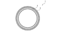
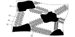
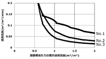
- FIG. 1 is a schematic perspective view showing a filtration membrane for oil-impregnated waste water treatment according to an embodiment of the present disclosure. It is the sectional view on the AA line of the filtration membrane for oil-impregnated waste water treatment of FIG. It is a schematic diagram which shows the microstructure of the filtration membrane for oil-impregnated waste water processing of FIG. It is a typical sectional view showing a filtration module for oil waste water disposal concerning one embodiment of this indication. It is a graph which shows the relationship between the cumulative filtration flow volume per membrane area of a filtration module of an Example and a comparative example (No. 1-No. 3), and filtration flux.
- the present disclosure has been made based on such circumstances, and is capable of suppressing clogging caused by the adhesion of oil while maintaining sufficient water permeability, and a filter membrane for oil-containing wastewater treatment and oil-containing wastewater treatment.
- the task is to provide a filtration module.
- the filter membrane for oil-impregnated waste water treatment and the filter module for oil-impregnated waste water treatment according to the present disclosure can suppress clogging due to adhesion of oil while maintaining sufficient water permeability.
- the filtration membrane for oil-impregnated waste water treatment is mainly composed of polytetrafluoroethylene, is laminated on the surface of the support layer having a large number of fibrous skeletons, and the support layer, and is mainly composed of polytetrafluoroethylene.
- each R 1 is independently a hydrogen atom or a methyl group.
- R 2 is a single bond or an alkanediyl group having 1 to 4 carbon atoms
- R 3 is a C 1 to C 20 perfluoroalkyl group or a C 3 to C 20 perfluorocycloalkyl group
- n is an integer of 1 to 50.
- R 4 is a single bond or an alkanediyl group having 1 to 10 carbon atoms
- R 5 is a monovalent hydrophilic group.
- the filter membrane for treatment of oil-containing wastewater has a heat resistance, mechanical strength and oil removal function. Excellent.
- the filtration membrane for oil-impregnated waste water treatment is represented by the first structural unit represented by the above-mentioned formula (1), and the above-mentioned formula (2) on the outer peripheral surface of many fibrous skeletons of the above-mentioned support layer and filter layer.
- the presence of a resin having a second structural unit and a third structural unit represented by the above formula (3) suppresses clogging due to adhesion of oil while maintaining sufficient water permeability. it can.
- the molar ratio of the first structural unit to the total of the second structural unit and the third structural unit in the resin is preferably 0.10 or more and 0.45 or less.
- the oil repellency can be enhanced while suppressing the decrease in water permeability, The adhesion of oil can be suppressed more reliably.
- the contact angle of pure water on the surface of the filtration layer is preferably 40 ° or more and 90 ° or less, and the contact angle of oil in water is preferably 80 ° or more and 150 ° or less.
- the oil repellency can be enhanced while the decrease in water permeability is suppressed, and the adhesion of the oil is further ensured. Can be suppressed.
- the oil-impregnated waste water treatment filter membrane may be a hollow fiber membrane in which the filter layer is disposed on the outer peripheral side.
- the oil-impregnated waste water treatment filter membrane is a hollow fiber membrane, so that the permeation of impurities including oil to the inner surface side of the support layer is prevented, and the impurities other than these impurities are transferred to the inner surface side of the support layer. By permeating, the oil in the oil-containing wastewater can be removed easily and reliably.
- the filter module for oil-impregnated waste water processing which concerns on the other one aspect of this indication is the said oil-impregnated waste water treatment filter membrane for the said oil-impregnated waste water which is a plurality of hollow fiber membranes aligned in one direction. And a pair of holding members for fixing both ends of the filtration membrane.
- the filter module for oil-impregnated waste water treatment comprises a plurality of the oil-impregnated waste water treatment filter membranes, these oil-impregnated waste water treatment filter membranes maintain sufficient water permeability while suppressing clogging due to adhesion of oil. can do.
- main component refers to a component with the largest content in terms of mass, and for example, a component with a content of 50 mass% or more.
- pure water contact angle refers to a value measured according to the static drop method of JIS-R 3257: 1999.
- oil-in-water contact angle on the surface of the filter layer refers to the contact angle measured by placing C heavy oil on the surface of the filter layer by placing it in water with the filter layer facing downward.
- the filtration membrane 1 for oil-impregnated waste water treatment shown in FIGS. 1 and 2 (hereinafter, also simply referred to as “filtration membrane 1”) is mainly composed of polytetrafluoroethylene (PTFE) and a support layer 2 having a large number of fibrous skeletons. And a filtration layer 3 laminated on the surface of the support layer 2 and mainly composed of PTFE and having a large number of fibrous skeletons.
- the said filtration membrane 1 is a 1st structural unit represented by following formula (1), and a 2nd structural unit represented by following formula (2) in the outer peripheral surface of many fibrous frame
- R 1 is each independently a hydrogen atom or a methyl group.
- R 2 is a single bond or an alkanediyl group having 1 to 4 carbon atoms.
- R 3 is a C 1-20 perfluoroalkyl group or a C 3-20 perfluorocycloalkyl group.
- n is an integer of 1 to 50.
- R 4 is a single bond or an alkanediyl group having 1 to 10 carbon atoms.
- R 5 is a monovalent hydrophilic group.
- the filtration membrane 1 is used to remove oil from oil-containing wastewater containing water-insoluble oil.
- the filtration membrane 1 is used, for example, to remove non-water-soluble oil from oil refinery wastewater or oil field associated water discharged in crude oil mining.
- both of the support layer 2 and the filtration layer 3 stacked on each other are mainly composed of PTFE, have a large number of fibrous skeletons, and a plurality of regions surrounded by the large number of fibrous skeletons. A void is formed.
- the said filtration membrane 1 performs a filtration process by making some void
- the filtration membrane 1 is represented by the first structural unit represented by the above formula (1), and the above formula (2) on the outer peripheral surface of a large number of fibrous skeletons of the support layer 2 and the filtration layer 3.
- a resin having a second structural unit and a third structural unit represented by the above formula (3) is present.
- the above-mentioned resin has a (meth) acrylate skeleton as a main chain, and a perfluoroalkyl group or a perfluorocycloalkyl group (hereinafter, also referred to as "perfluoro (cyclo) alkyl group”) in a side chain, a polyoxyethylene alkyl ether group And a monovalent hydrophilic group.
- the perfluoro (cyclo) alkyl group is water and oil repellent, and the polyoxyethylene alkyl ether group and the monovalent hydrophilic group are hydrophilic.
- a perfluoro group-containing compound having a perfluoro (cyclo) alkyl group in the side chain is present on the outer peripheral surface of a large number of fibrous skeletons mainly composed of PTFE, the surface tension of the membrane surface can be reduced, Oily can be expressed.
- the water permeability is increased because the oil repellency and the water repellency are enhanced.
- the filtration membrane 1 is a two-layer structure in which the support layer 2 and the filtration layer 3 are directly laminated.
- the filtration membrane 1 can improve water permeability and mechanical strength by providing the support layer 2 and the filtration layer 3.
- the support layer 2 and the filter layer 3 may contain other fluororesins and additives as long as the desired effects of the present disclosure are not impaired.
- the additives include pigments for coloring, inorganic fillers for improving abrasion resistance, preventing low temperature flow, and facilitating formation of pores, metal powder, metal oxide powder, metal sulfide powder and the like.
- the filtration membrane 1 is a hollow fiber membrane in which the filtration layer 3 is disposed on the outer peripheral side. Since the filtration membrane 1 is a hollow fiber membrane in which the filtration layer 3 is disposed on the outer peripheral side of the support layer 2, these impurities are prevented from being transmitted to the inner surface side of the support layer 2 while these impurities By permeating the other components to the inner surface side of the support layer 2, the oil component in the oil-containing wastewater can be removed easily and reliably.
- the lower limit of the average inner diameter of the filtration membrane 1 is preferably 0.3 mm, more preferably 0.5 mm.
- an upper limit of the mean inside diameter of the filtration membrane 1 12.0 mm is preferable and 6.0 mm is more preferable. If the above-mentioned average inner diameter is smaller than the above-mentioned lower limit, there is a possibility that the pressure loss when discharging the filtered water which has permeated to the inner surface side of the support layer 2 may become large. Conversely, if the average inner diameter exceeds the upper limit, the size of the filtration module using the filtration membrane 1 may be increased, and the filtration efficiency per unit volume may be insufficient.
- the fibrous skeletons of the support layer 2 and the filtration layer 3 will be described with reference to FIG.
- the fibrous framework has a network structure in which a particle mass (secondary particles) called node 11 is connected by a fibrous portion called fibrils 12.
- fibrils 12 In the support layer 2 and the filtration layer 3, gaps between the fibrils 12 or between the fibrils 12 and the nodes 11 form pores.
- the resin is, as described above, the first structural unit represented by the formula (1), the second structural unit represented by the formula (2), and the third structural unit represented by the formula (3) Have.
- the above resin is composed of a main skeleton 13 consisting of a (meth) acrylate skeleton, a water and oil repellent group 14 consisting of a perfluoroalkyl group or a perfluorocycloalkyl group, a polyoxyethylene alkyl ether group and a monovalent hydrophilic group. And the following hydrophilic group 15.
- the above-mentioned resin is non-crosslinked and fixed to the outer peripheral surface of a large number of fibrous skeletons of PTFE by the physical interaction between the perfluoro (cyclo) alkyl group and the PTFE, as well as the anchor effect.
- Examples of the alkanediyl group having 1 to 4 carbon atoms represented by R 2 in the above formula (1) in the first structural unit include a methanediyl group, an ethanediyl group, a propanediyl group, a butanediyl group and the like.
- an alkanediyl group is preferable, and an ethanediyl group is more preferable.
- Examples of the C 1 -C 20 perfluoroalkyl group represented by R 3 in the above formula (1) in the first structural unit include —C m F 2m + 1 and the like. m is an integer of 1 to 20.
- m As a lower limit of m, 2 is preferable and 4 is more preferable. As an upper limit of m, 15 is preferable and 10 is more preferable.
- Examples of the perfluorocycloalkyl group having 3 to 20 carbon atoms represented by R 3 in the above-mentioned formula (1) include nonafluorocyclopentyl group and undecafluorocyclohexyl group.
- a perfluoroalkyl group is preferable, a C 4-10 perfluoroalkyl group is more preferable, and a tridecafluorohexyl group is more preferable.
- R 1 is a hydrogen atom or a methyl group.
- n of the said Formula (2) in a 2nd structural unit 2 is preferable and 5 is more preferable.
- the upper limit of n is preferably 40, and more preferably 30.
- a methanediyl group, ethanediyl group, butanediyl group, hexanediyl group, octanediyl group, decanediyl group etc. are mentioned, for example Can be mentioned.
- an alkanediyl group is preferable, an alkanediyl group having 1 to 4 carbon atoms is more preferable, and an ethanediyl group is more preferable.
- substituted amino group examples include alkylamino groups such as methylamino group and ethylamino group, and dialkylamino groups such as dimethylamino group and diethylamino group.
- amide group for example, -CONR 2 (R is each independently a hydrogen atom or a monovalent hydrocarbon group having 1 to 10 carbon atoms), -N (R ') COR' (R 'is each independently And hydrogen atoms or monovalent hydrocarbon groups having 1 to 10 carbon atoms).
- a (substituted) amino group is preferable, a dialkylamino group is more preferable, and a dimethylamino group is more preferable.
- the lower limit of the molar ratio of the first structural unit to the total of the second structural unit and the third structural unit in the resin is preferably 0.10, and more preferably 0.15.
- the upper limit of the molar ratio is preferably 0.45, and more preferably 0.25. If the molar ratio is less than the above lower limit, oil repellency may be insufficient, and adhesion of oil may not be sufficiently suppressed. Conversely, when the molar ratio exceeds the upper limit, the water wettability may be insufficient, and the water permeability may be insufficient.
- the upper limit of the molar ratio is preferably 0.85, more preferably 0.80. If the molar ratio is outside the above range, control of the hydrophilicity of the resin may not be easy.
- the resin is present substantially uniformly on the entire outer peripheral surface of the fibrous layers of the support layer 2 and the filter layer 3. That is, the resin is present on the surface and inside of the support layer 2 and the filtration layer 3.
- 4.0 ⁇ g / mm 3 is preferable, and 5.0 ⁇ g / mm 3 is more preferable.
- 10.0 ⁇ g / mm 3 is preferable, and 8.0 ⁇ g / mm 3 is more preferable.
- the amount of adhesion is less than the above lower limit, there is a possibility that it becomes difficult to sufficiently increase the oil repellency.
- the above-mentioned fixed amount exceeds the above-mentioned upper limit, there is a possibility that the existence rate of the above-mentioned resin becomes high unnecessarily, and the manufacturing cost of the filtration membrane 1 concerned becomes needlessly high.
- the said resin is laminated
- the lower limit of the average thickness of the resin layers laminated on the outer peripheral surface of the large number of fibrous skeletons is preferably 5 nm, more preferably 10 nm.
- an upper limit of the average thickness of the said resin layer 50 nm is preferable and 30 nm is more preferable. If the above average thickness is smaller than the above lower limit, there is a possibility that it becomes difficult to sufficiently improve the oil repellency.
- the thickness of the resin layer means energy dispersive X-ray analysis (EDX) in cross-sectional images in the thickness direction of the support layer and the filtration layer taken by a transmission electron microscope (TEM). It refers to the thickness of the specified resin.
- average thickness means the average value of thickness of arbitrary 10 points
- the support layer 2 is a tube body obtained by extruding a support layer forming material containing, for example, PTFE. As described above, by forming the support layer 2 by extrusion molding, the mechanical strength of the support layer 2 can be enhanced and the pores can be easily formed.
- the support layer 2 is preferably formed by being stretched in the axial direction and the circumferential direction after extrusion.
- the stretch ratio in the axial direction can be, for example, 50% to 700%, and the stretch ratio in the circumferential direction can be, for example, 5% to 100%.
- the size and shape of the pores can be adjusted in the support layer 2 by adjusting the stretching conditions such as the stretching temperature and the stretching ratio.
- the lower limit of the average thickness of the support layer 2 is preferably 0.1 mm, more preferably 0.3 mm.
- an upper limit of the average thickness of the support layer 2 3.0 mm is preferable and 1.0 mm is more preferable. If the average thickness is smaller than the lower limit, the mechanical strength of the support layer 2 may be insufficient. Conversely, when the average thickness exceeds the upper limit, the water permeability of the support layer 2 may be reduced.
- the lower limit of the average pore diameter of the support layer 2 is preferably 0.5 ⁇ m, more preferably 1.0 ⁇ m.
- the upper limit of the average pore diameter of the support layer 2 is preferably 5.0 ⁇ m, more preferably 3.0 ⁇ m.
- the “average pore diameter” of the support layer means the average diameter of the pores on the surface of the support layer, and is measured by a pore diameter distribution measuring apparatus (for example, palm porometer “CFP-1200A” manufactured by PMI). Can.
- the lower limit of the porosity of the support layer 2 is preferably 40% by volume, and more preferably 50% by volume.
- the upper limit of the porosity of the support layer 2 is preferably 90% by volume, more preferably 85% by volume. If the porosity is less than the above lower limit, the water permeability may be reduced and the filtration efficiency may be insufficient. On the other hand, when the porosity exceeds the upper limit, the mechanical strength of the support layer 2 may be insufficient.
- the “porosity” of the support layer refers to the ratio of the total volume of pores to the volume of the support layer, and can be determined by measuring the density of the support layer in accordance with ASTM-D-792.
- the filtration layer 3 is formed, for example, by winding and sintering a sheet having a large number of fibrous skeletons around the outer peripheral surface of the support layer 2, for example, based on PTFE.
- the stretching condition is adjusted and then the above-mentioned sheet body is stretched, so that the size and shape of the pores, and the thickness of the filtration layer 3 Can be easily adjusted.
- the support layer 2 and the filtration layer 3 can be integrated, and the pores of both can be communicated to enhance water permeability.
- the draw ratio in the longitudinal direction of the sheet can be, for example, 50% or more and 1000% or less, and the draw ratio in the short direction can be 50% or more and 2500% or less.
- the thickness of the filtration layer 3 is preferably smaller than the thickness of the support layer 2.
- an upper limit of average thickness of filtration layer 3 100 micrometers is preferred and 50 micrometers is more preferred. If the above average thickness is smaller than the above lower limit, the mechanical strength of the filtration layer 3 may be insufficient. On the contrary, when the above-mentioned average thickness exceeds the above-mentioned upper limit, there is a possibility that water permeability of filtration layer 3 may fall.
- the lower limit of the average pore diameter of the filtration layer 3 is preferably 0.01 ⁇ m, more preferably 0.05 ⁇ m.
- the upper limit of the average pore diameter of the filtration layer 3 is preferably 0.45 ⁇ m, more preferably 0.20 ⁇ m.
- the porosity of the filtration layer 3 can be in the same range as the porosity of the support layer 2 described above.
- a pure water contact angle on the surface of filtration layer 3 40 degrees is preferred and 50 degrees is more preferred.
- an upper limit of the pure water contact angle of the surface of filtration layer 3 90 degrees is preferred and 80 degrees is more preferred. If the pure water contact angle is less than the above lower limit, the oil repellency of the filter layer 3 may not be sufficiently improved. Conversely, when the pure water contact angle exceeds the upper limit, the water permeability of the filtration layer 3 may be insufficient.
- the lower limit of the oil-in-water contact angle of the surface of the filter layer 3 is preferably 80 °, more preferably 120 °.
- an upper limit of the oil-in-water contact angle of filtration layer 3 surface 150 degrees is preferred and 140 degrees is more preferred. If the above-mentioned oil-in-water contact angle is less than the above-mentioned minimum, oil repellency of filter layer 3 will become insufficient, and there is a possibility that clogging by adhesion of oil can not fully be controlled. Conversely, when the oil-in-water contact angle exceeds the upper limit, the water permeability of the filtration layer 3 may not be sufficiently improved.
- the oil-in-water contact angle on the surface of the filter layer 3 is preferably larger than the pure water contact angle.
- a difference of an oil-in-water contact angle on the surface of filtration layer 3, and a pure water contact angle 20 degrees is preferred and 40 degrees is more preferred.
- an upper limit of the said difference 100 degrees is preferable and 80 degrees is more preferable.
- the difference is smaller than the lower limit, it may be difficult to sufficiently increase the oil repellency while suppressing the decrease in water permeability. Conversely, when the difference exceeds the upper limit, the formation of the filtration layer 3 becomes difficult, and the manufacturing cost may be increased.
- the method for producing the filtration membrane 1 comprises a laminate forming step of forming a laminate in which the support layer 2 and the filtration layer 3 are laminated, and a large number of the support layers 2 and filtration layers 3 laminated in the laminate formation step. It has a first structural unit represented by the above formula (1), a second structural unit represented by the above formula (2), and a third structural unit represented by the above formula (3) on the outer peripheral surface of the fibrous skeleton And fixing the resin.
- the support layer is formed on the outer peripheral surface of a support layer forming tube obtained by extruding a support layer forming material obtained by blending a liquid lubricant such as naphtha with fine powder into a tube shape.
- a filtration layer-forming sheet formed by extruding a filtration layer-forming material made of the same material as the material into a sheet is laminated.
- seat for filtration layer formation around the outer peripheral surface of the said tube for support layer formation is mentioned, for example.
- the support layer-forming tube and the filtration layer-forming sheet may be unfired or may be fired.
- the number of times of winding of the filtration layer forming sheet can be adjusted by the thickness of the sheet, and can be made once or plural times.
- the support layer forming tube and the filtration layer forming sheet are sintered in a state where the filtration layer forming sheet is laminated on the support layer forming tube.
- the support layer 2 and the filtration layer 3 are integrated by sintering the support layer forming tube and the filtration layer forming sheet in a state of being laminated to each other, and the holes of both are communicated with each other. Permeability can be improved.
- the fixing step includes a pre-wet treatment step of wetting the laminate formed in the laminate formation step with a solvent, an application step of applying the resin to the laminate after the pre-wet treatment, and the resin after the application step And d) drying.
- the above-mentioned fixing step the above-mentioned resin is non-cross-linked and fixed to the outer peripheral surface of a large number of fibrous skeletons of PTFE by the physical interaction between the perfluoroalkyl group or perfluorocycloalkyl group and PTFE and the anchor effect.
- the solvent include alcohols, surfactant solutions and the like.
- Examples of the coating method include a method of immersing the laminate in an aqueous dispersion in which the resin is dispersed in water. As described above, by immersing the laminate in an aqueous dispersion in which the resin is dispersed in water, the resin can be substantially uniformly fixed to the entire region of the outer peripheral surface of many fibrous skeletons of PTFE. .
- the method for producing the filtration membrane can produce the filtration membrane 1 easily and reliably.
- filtration module 21 for oil-impregnated waste water treatment (hereinafter, also simply referred to as “filtration module 21”) having the filtration membrane 1 of FIGS. 1 and 2 will be described.
- the filtration module 21 includes a plurality of filtration membranes 1 aligned in one direction, and a pair of holding members (upper holding member 22 and lower holding member 23) for fixing both ends of the plurality of filtration membranes 1. Equipped with
- the filtration module 21 is used to remove oil from oil-containing wastewater containing non-water-soluble oil.
- the filtration module 21 is an external pressure type which makes the outer peripheral surface side of the filtration membrane 1 have a high pressure and permeates filtered water to the inner peripheral surface side of the filtration membrane 1 and the negative pressure of the inner peripheral surface side of the filtration membrane 1 It is suitably used for an immersion type (also referred to as suction type) filtration device that allows permeation to the inner peripheral surface side of the filtration membrane.
- the filtration module 21 includes a plurality of the filtration membranes 1, it is possible to suppress clogging due to adhesion of oil while maintaining sufficient water permeability.
- the upper holding member 22 is formed in a rod-like and hollow shape.
- the upper holding member 22 fixes upper ends of the plurality of filtration membranes 1.
- the upper holding member 22 is formed in an internal space 22a communicating with the inner cavity of the plurality of filtration membranes 1 and one end (upper end in the present embodiment) of the internal space 22a and filtered by the plurality of filtration membranes 1 And an outlet 22b capable of discharging the filtered water.
- the lower holding member 23 is formed in a rod shape.
- the lower side holding member 23 may have an internal space like the upper side holding member 22, and lower end portions of the plurality of filtration membranes 1 may be closed by closing the lower openings of the plurality of filtration membranes 1. You may hold it.
- the shape of the filtration membrane can be designed according to the configuration of the filtration device to be applied, and may be, for example, a flat membrane. Further, the filtration membrane is preferably a two-layer structure of a support layer and a filtration layer, but may have other layers other than the support layer and the filtration layer.
- the hollow fiber membrane was prewet with alcohol. Subsequently, it has a first structural unit represented by the above formula (4), a second structural unit represented by the above formula (2), and a third structural unit represented by the above formula (3), N in (2) is 10, R 4 in the above formula (3) is an ethanediyl group, R 5 is a dimethylamino group, and R 1 in the above formulas (2) to (4) is a methyl group
- the pre-wet hollow fiber membrane was immersed in an aqueous dispersion in which a certain resin was uniformly dispersed in water. Then, the said resin was dried and the filtration membrane was manufactured by making the said resin adhere to the said hollow fiber membrane.
- the molar ratio of the first structural unit, the second structural unit, and the third structural unit was 3: 4: 3.
- the upper ends of the plurality of filtration membranes aligned in one direction are fixed to an upper holding member having an internal space communicating with the lumens of the filtration membranes and an outlet formed at the upper end of the internal space; And the filtration module of membrane effective area 18 cm ⁇ 2 > which fixed the lower end part of these filtration membranes to the lower side holding member was manufactured.
- occludes the lower opening of several filtration membranes was used as a lower side holding member.
- Frtration module A plurality of the above-mentioned filtration membranes are referred By fixing to the upper side holding member and the lower side holding member similar to 1, a filtration module with a membrane effective area of 18 cm 2 was manufactured.
- No. 1 filter module had a filtration flux of 0.065 m 3 / m 2 / min when the cumulative filtration flow rate per membrane area was 2.0 m 3 / m 2 .
- No. 2 filtration module had a surface area of 0.030 m 3 / m 2 / min.
- the filtration module of No. 3 has 0.017 m 3 / m 2 / min. That is, no. In the filtration module of No. 1, the filtration flux at the time when the cumulative filtration flow rate reached 2.0 m 3 / m 2 was No. 1 2.17 times of No. 2 filtration module, No. It is 3.82 times of 3 filtration modules. From this, No. No. 1 filtration module has no. 2 and No. It can be understood that clogging due to adhesion of oil can be prevented while maintaining water permeability as compared with the third filtration module.
- the filtration membrane of No. 1 is excellent in both water permeability and oil repellency when the contact angle of pure water on the surface of the filtration layer is 40 ° and the contact angle of oil in water is 128 °.
- the filter membrane of No. 2 has a large pure water contact angle of 126 ° and low water permeability.
- no. The filter membrane No. 3 has a pure water contact angle of 120 ° and an oil-in-water contact angle of 50 °, and both water permeability and oil repellency are low.
Landscapes
- Chemical & Material Sciences (AREA)
- Chemical Kinetics & Catalysis (AREA)
- Life Sciences & Earth Sciences (AREA)
- Hydrology & Water Resources (AREA)
- Engineering & Computer Science (AREA)
- Environmental & Geological Engineering (AREA)
- Water Supply & Treatment (AREA)
- Organic Chemistry (AREA)
- Physics & Mathematics (AREA)
- Thermal Sciences (AREA)
- Separation Using Semi-Permeable Membranes (AREA)
- Addition Polymer Or Copolymer, Post-Treatments, Or Chemical Modifications (AREA)
Abstract
本発明の一態様に係る含油排水処理用濾過膜は、ポリテトラフルオロエチレンを主成分とし、多数の繊維状骨格を有する支持層と、この支持層の表面に積層され、ポリテトラフルオロエチレンを主成分とし、多数の繊維状骨格を有する濾過層とを備え、上記支持層及び濾過層の多数の繊維状骨格の外周面に下記式(1)で表される第1構造単位、下記式(2)で表される第2構造単位及び下記式(3)で表される第3構造単位を有する樹脂が存在している。
Description
本開示は、含油排水処理用濾過膜及び含油排水処理用濾過モジュールに関する。本出願は、2017年12月27日出願の日本出願第2017-250918号に基づく優先権を主張し、前記日本出願に記載された全ての記載内容を援用するものである。
含油排水から油分を除去するために濾過膜が用いられている。この濾過膜は、含油排水に含まれる油分及びその他の不純物の透過を防ぎつつ、これらの不純物以外を透過させることで濾過処理を行う。この濾過膜としては、優れた油分の除去機能を有し、かつ耐熱性、機械的強度等に優れる点から、ポリテトラフルオロエチレン(PTFE)を主成分とする多孔質膜が使用されている(特開2010-36183号公報参照)。
本開示の一態様に係る含油排水処理用濾過膜は、ポリテトラフルオロエチレンを主成分とし、多数の繊維状骨格を有する支持層と、この支持層の表面に積層され、ポリテトラフルオロエチレンを主成分とし、多数の繊維状骨格を有する濾過層とを備え、上記支持層及び濾過層の多数の繊維状骨格の外周面に下記式(1)で表される第1構造単位、下記式(2)で表される第2構造単位及び下記式(3)で表される第3構造単位を有する樹脂が存在している。
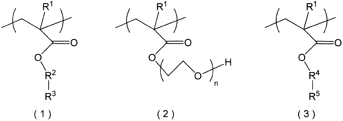
(式(1)~(3)中、R1は、それぞれ独立して、水素原子又はメチル基である。式(1)中、R2は、単結合又は炭素数1~4のアルカンジイル基である。また、R3は、炭素数1~20のパーフルオロアルキル基又は炭素数3~20のパーフルオロシクロアルキル基である。式(2)中、nは、1~50の整数である。式(3)中、R4は、単結合又は炭素数1~10のアルカンジイル基である。また、R5は、1価の親水基である。)
本開示の他の一態様に係る含油排水処理用濾過モジュールは、一方向に引き揃えられた複数本の中空糸膜である当該含油排水処理用濾過膜と、上記複数本の当該含油排水処理用濾過膜の両端部を固定する一対の保持部材とを備える。
[本開示が解決しようとする課題]
特許文献1に記載のPTFEを主成分とする濾過膜は、継続して使用するうちに油分が膜表面に付着しやすい。そのため、この濾過膜は、油分の付着に起因する目詰まりを防止する点でさらなる改良の余地がある。
特許文献1に記載のPTFEを主成分とする濾過膜は、継続して使用するうちに油分が膜表面に付着しやすい。そのため、この濾過膜は、油分の付着に起因する目詰まりを防止する点でさらなる改良の余地がある。
本開示は、このような事情に基づいてなされたものであり、十分な通水性を維持しつつ油分の付着に起因する目詰まりを抑制することができる含油排水処理用濾過膜及び含油排水処理用濾過モジュールの提供を課題とする。
[本開示の効果]
[本開示の効果]
本開示に係る含油排水処理用濾過膜及び含油排水処理用濾過モジュールは、十分な通水性を維持しつつ油分の付着に起因する目詰まりを抑制することができる。
[本開示の実施形態の説明]
最初に本開示の実施態様を列記して説明する。
最初に本開示の実施態様を列記して説明する。
本開示の一態様に係る含油排水処理用濾過膜は、ポリテトラフルオロエチレンを主成分とし、多数の繊維状骨格を有する支持層と、この支持層の表面に積層され、ポリテトラフルオロエチレンを主成分とし、多数の繊維状骨格を有する濾過層とを備え、上記支持層及び濾過層の多数の繊維状骨格の外周面に下記式(1)で表される第1構造単位、下記式(2)で表される第2構造単位及び下記式(3)で表される第3構造単位を有する樹脂が存在している。

(式(1)~(3)中、R1は、それぞれ独立して、水素原子又はメチル基である。式(1)中、R2は、単結合又は炭素数1~4のアルカンジイル基である。また、R3は、炭素数1~20のパーフルオロアルキル基又は炭素数3~20のパーフルオロシクロアルキル基である。式(2)中、nは、1~50の整数である。式(3)中、R4は、単結合又は炭素数1~10のアルカンジイル基である。また、R5は、1価の親水基である。)
当該含油排水処理用濾過膜は、互いに積層される支持層及び濾過層が何れもポリテトラフルオロエチレンを主成分とし、多数の繊維状骨格を有するので、耐熱性、機械的強度及び油分除去機能に優れる。また、当該含油排水処理用濾過膜は、上記支持層及び濾過層の多数の繊維状骨格の外周面に上記式(1)で表される第1構造単位、上記式(2)で表される第2構造単位及び上記式(3)で表される第3構造単位を有する樹脂が存在していることで、十分な通水性を維持しつつ油分の付着に起因する目詰まりを抑制することができる。
上記樹脂における第2構造単位及び第3構造単位の合計に対する第1構造単位のモル比としては0.10以上0.45以下が好ましい。このように、上記樹脂における第2構造単位及び第3構造単位の合計に対する第1構造単位のモル比が上記範囲内であることによって、通水性の低下を抑えつつ撥油性を高めることができ、油分の付着をより確実に抑制することができる。
上記濾過層表面の純水接触角としては40°以上90°以下が好ましく、水中油接触角としては80°以上150°以下が好ましい。このように、上記濾過層表面の純水接触角及び水中油接触角がいずれも上記範囲内であることによって、通水性の低下を抑えつつ撥油性を高めることができ、油分の付着をより確実に抑制することができる。
当該含油排水処理用濾過膜は、上記濾過層が外周側に配置された中空糸膜であるとよい。このように、当該含油排水処理用濾過膜が中空糸膜であることによって、油分を含む不純物の上記支持層の内面側への透過を防ぎつつ、これらの不純物以外を上記支持層の内面側に透過させることで、含油排水中の油分を容易かつ確実に除去することができる。
また、本開示の他の一態様に係る含油排水処理用濾過モジュールは、一方向に引き揃えられた複数本の中空糸膜である当該含油排水処理用濾過膜と、上記複数本の含油排水処理用濾過膜の両端部を固定する一対の保持部材とを備える。
当該含油排水処理用濾過モジュールは、複数本の当該含油排水処理用濾過膜を備えるので、これらの含油排水処理用濾過膜によって十分な通水性を維持しつつ油分の付着に起因する目詰まりを抑制することができる。
なお、本開示において、「主成分」とは、質量換算で最も含有量の多い成分をいい、例えば含有量が50質量%以上の成分をいう。「純水接触角」とは、JIS-R3257:1999の静滴法に準拠して測定される値をいう。濾過層表面の「水中油接触角」とは、濾過層が下側になるように水中に置き、濾過層の表面にC重油を着滴させて測定される接触角をいう。
[本開示の実施形態の詳細]
以下、適宜図面を参照しつつ、本開示の一実施形態に係る含油排水処理用濾過膜及び含油排水処理用濾過モジュールについて説明する。
以下、適宜図面を参照しつつ、本開示の一実施形態に係る含油排水処理用濾過膜及び含油排水処理用濾過モジュールについて説明する。
[含油排水処理用濾過膜]
図1及び図2の含油排水処理用濾過膜1(以下、単に「濾過膜1」ともいう)は、ポリテトラフルオロエチレン(PTFE)を主成分とし、多数の繊維状骨格を有する支持層2と、支持層2の表面に積層され、PTFEを主成分とし、多数の繊維状骨格を有する濾過層3とを備える。当該濾過膜1は、支持層2及び濾過層3の多数の繊維状骨格の外周面に下記式(1)で表される第1構造単位、下記式(2)で表される第2構造単位及び下記式(3)で表される第3構造単位を有する樹脂が存在している。
図1及び図2の含油排水処理用濾過膜1(以下、単に「濾過膜1」ともいう)は、ポリテトラフルオロエチレン(PTFE)を主成分とし、多数の繊維状骨格を有する支持層2と、支持層2の表面に積層され、PTFEを主成分とし、多数の繊維状骨格を有する濾過層3とを備える。当該濾過膜1は、支持層2及び濾過層3の多数の繊維状骨格の外周面に下記式(1)で表される第1構造単位、下記式(2)で表される第2構造単位及び下記式(3)で表される第3構造単位を有する樹脂が存在している。

式(1)~(3)中、R1は、それぞれ独立して、水素原子又はメチル基である。式(1)中、R2は、単結合又は炭素数1~4のアルカンジイル基である。また、R3は、炭素数1~20のパーフルオロアルキル基又は炭素数3~20のパーフルオロシクロアルキル基である。式(2)中、nは、1~50の整数である。式(3)中、R4は、単結合又は炭素数1~10のアルカンジイル基である。また、R5は、1価の親水基である。
当該濾過膜1は、非水溶性油分を含む含油排水から油分を除去するために用いられる。当該濾過膜1は、例えば含油工場排水や、原油採掘に際して排出される油田随伴水から非水溶性油分を除去するために用いられる。
当該濾過膜1は、互いに積層される支持層2及び濾過層3が何れもPTFEを主成分とし、多数の繊維状骨格を有しており、上記多数の繊維状骨格に囲まれる領域に複数の空孔が形成されている。当該濾過膜1は、含油排水中の油分を含む不純物の透過を上記複数の繊維状骨格で防ぎつつ、これらの不純物以外については複数の空孔を透過させることで濾過処理を行う。当該濾過膜1は、支持層2及び濾過層3がPTFEを主成分とするので、耐熱性、機械的強度及び油分除去機能に優れる。
当該濾過膜1は、上述のように、支持層2及び濾過層3の多数の繊維状骨格の外周面に上記式(1)で表される第1構造単位、上記式(2)で表される第2構造単位及び上記式(3)で表される第3構造単位を有する樹脂が存在している。上記樹脂は、(メタ)アクリレート骨格を主鎖とし、側鎖にパーフルオロアルキル基又はパーフルオロシクロアルキル基(以下、「パーフルオロ(シクロ)アルキル基」ともいう)と、ポリオキシエチレンアルキルエーテル基と、1価の親水基とを有している。上記パーフルオロ(シクロ)アルキル基は撥水撥油性であり、上記ポリオキシエチレンアルキルエーテル基と1価の親水基とは親水性である。PTFEを主成分とする多数の繊維状骨格の外周面にパーフルオロ(シクロ)アルキル基を側鎖に有するパーフルオロ基含有化合物が存在する場合、膜表面の表面張力を低下させることができ、撥油性を発現することができる。しかしながら、この場合、撥油性と共に撥水性も高められるため通水性が不十分となる。これに対し、本発明者が鋭意検討したところ、このパーフルオロ基含有化合物にポリオキシエチレンアルキルエーテル基と親水基とを導入することで、水濡れ性を適切に向上し、十分な通水性を維持しつつ油分の付着に起因する目詰まりを抑制することができる。
当該濾過膜1は、支持層2及び濾過層3が直接積層された2層構造体である。当該濾過膜1は、支持層2及び濾過層3を備えることで、通水性及び機械的強度を高めることができる。なお、支持層2及び濾過層3は、PTFEの他、本開示の所望の効果を害しない範囲で他のフッ素樹脂や添加剤を含有していてもよい。上記添加剤としては、例えば着色のための顔料や、耐摩耗性改良、低温流れ防止、空孔生成容易化のための無機充填剤、金属粉、金属酸化物粉、金属硫化物粉等が挙げられる。
当該濾過膜1は、濾過層3が外周側に配置された中空糸膜である。当該濾過膜1は、濾過層3が支持層2の外周側に配置された中空糸膜であることによって、油分を含む不純物が支持層2の内面側に透過することを防ぎつつ、これらの不純物以外を支持層2の内面側に透過させることで、含油排水中の油分を容易かつ確実に除去することができる。
当該濾過膜1の平均内径の下限としては、0.3mmが好ましく、0.5mmがより好ましい。一方、当該濾過膜1の平均内径の上限としては、12.0mmが好ましく、6.0mmがより好ましい。上記平均内径が上記下限より小さいと、支持層2の内面側に透過した濾過水を排出する時の圧損が大きくなるおそれがある。逆に、上記平均内径が上記上限を超えると、当該濾過膜1を用いた濾過モジュールのサイズが大きくなり、単位体積当たりの濾過効率が不十分となるおそれがある。
図3を参照して、支持層2及び濾過層3の繊維状骨格について説明する。上記繊維状骨格は、ノード11と称される粒子塊(2次粒子)がフィブリル12と称される繊維状の部分で繋がれた網状構造を有する。支持層2及び濾過層3は、フィブリル12間、又はフィブリル12とノード11との間の間隙が空孔を形成している。
〈樹脂〉
上記樹脂は、上述のように、上記式(1)で表される第1構造単位、上記式(2)で表される第2構造単位及び上記式(3)で表される第3構造単位を有する。上記樹脂は、(メタ)アクリレート骨格からなる主骨格13と、パーフルオロアルキル基又はパーフルオロシクロアルキル基からなる撥水撥油基14と、ポリオキシエチレンアルキルエーテル基と1価の親水基とからなる親水基15とを有する。上記樹脂は、パーフルオロ(シクロ)アルキル基とPTFEとの物理的相互作用、並びにアンカー効果によって、PTFEの多数の繊維状骨格の外周面に非架橋固着されている。
上記樹脂は、上述のように、上記式(1)で表される第1構造単位、上記式(2)で表される第2構造単位及び上記式(3)で表される第3構造単位を有する。上記樹脂は、(メタ)アクリレート骨格からなる主骨格13と、パーフルオロアルキル基又はパーフルオロシクロアルキル基からなる撥水撥油基14と、ポリオキシエチレンアルキルエーテル基と1価の親水基とからなる親水基15とを有する。上記樹脂は、パーフルオロ(シクロ)アルキル基とPTFEとの物理的相互作用、並びにアンカー効果によって、PTFEの多数の繊維状骨格の外周面に非架橋固着されている。
第1~第3構造単位における上記式(1)~(3)のR1としては、メチル基が好ましい。
第1構造単位における上記式(1)のR2で表される炭素数1~4のアルカンジイル基としては、例えばメタンジイル基、エタンジイル基、プロパンジイル基、ブタンジイル基等が挙げられる。
R2としては、アルカンジイル基が好ましく、エタンジイル基がより好ましい。
第1構造単位における上記式(1)のR3で表される炭素数1~20のパーフルオロアルキル基としては、例えば-CmF2m+1等が挙げられる。mは、1~20の整数である。
mの下限としては、2が好ましく、4がより好ましい。mの上限としては、15が好ましく、10がより好ましい。
上記式(1)のR3で表される炭素数3~20のパーフルオロシクロアルキル基としては、例えばノナフルオロシクロペンチル基、ウンデカフルオロシクロヘキシル基等が挙げられる。
R3としては、パーフルオロアルキル基が好ましく、炭素数4~10のパーフルオロアルキル基がより好ましく、トリデカフルオロヘキシル基がさらに好ましい。
上記第1構造単位の具体例としては、例えば下記式(4)で表される構造単位等が挙げられる。
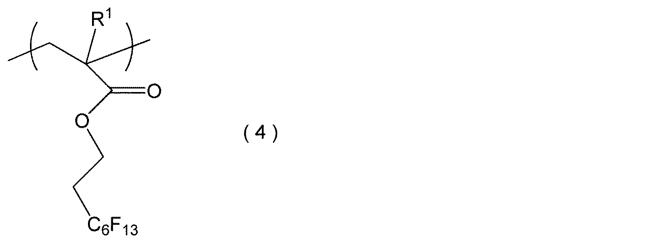
式(4)中、R1は水素原子又はメチル基である。
第2構造単位における上記式(2)のnの下限としては、2が好ましく、5がより好ましい。nの上限としては、40が好ましく、30がより好ましい。
第3構造単位における上記式(3)のR4で表される炭素数1~10のアルカンジイル基としては、例えばメタンジイル基、エタンジイル基、ブタンジイル基、ヘキサンジイル基、オクタンジイル基、デカンジイル基等が挙げられる。
R4としては、アルカンジイル基が好ましく、炭素数1~4のアルカンジイル基がより好ましく、エタンジイル基がさらに好ましい。
上記R5で表される1価の親水基としては、例えばアミノ基(置換アミノ基を含む)、アミド基、ヒドロキシ基等が挙げられる。
置換アミノ基としては、例えばメチルアミノ基、エチルアミノ基等のアルキルアミノ基、ジメチルアミノ基、ジエチルアミノ基等のジアルキルアミノ基などが挙げられる。
アミド基としては、例えば-CONR2(Rは、それぞれ独立して、水素原子又は炭素数1~10の1価の炭化水素基)、-N(R’)COR’(R’は、それぞれ独立して、水素原子又は炭素数1~10の1価の炭化水素基)等が挙げられる。
R5としては、(置換)アミノ基が好ましく、ジアルキルアミノ基がより好ましく、ジメチルアミノ基がさらに好ましい。
上記樹脂における第2構造単位及び第3構造単位の合計に対する第1構造単位のモル比の下限としては、0.10が好ましく、0.15がより好ましい。一方、上記モル比の上限としては、0.45が好ましく、0.25がより好ましい。上記モル比が上記下限に満たないと、撥油性が不十分となり、油分の付着を十分に抑制できなくなるおそれがある。逆に、上記モル比が上記上限を超えると、水濡れ性が不足して、通水性が不十分となるおそれがある。
上記樹脂における第2構造単位に対する第3構造単位のモル比の下限としては、0.50が好ましく、0.65がより好ましい。一方、上記モル比の上限としては、0.85が好ましく、0.80がより好ましい。上記モル比が上記範囲外であると、上記樹脂の親水性の制御が容易でなくなるおそれがある。
上記樹脂は、支持層2及び濾過層3の多数の繊維状骨格の外周面の全面に略均一に存在している。つまり、上記樹脂は、支持層2及び濾過層3の表面及び内部に存在している。支持層2及び濾過層3の全体における上記樹脂の固着量の下限としては、4.0μg/mm3が好ましく、5.0μg/mm3がより好ましい。一方、支持層2及び濾過層3の全体における上記樹脂の固着量の上限としては、10.0μg/mm3が好ましく、8.0μg/mm3がより好ましい。上記固着量が上記下限に満たないと、撥油性を十分に高め難くなるおそれがある。逆に、上記固着量が上記上限を超えると、上記樹脂の存在割合が不要に高くなり、当該濾過膜1の製造コストが不要に高くなるおそれがある。
上記樹脂は、支持層2及び濾過層3の多数の繊維状骨格の外周面上に層状に積層されていることが好ましい。この場合、上記多数の繊維状骨格の外周面上に積層される樹脂層の平均厚さの下限としては、5nmが好ましく、10nmがより好ましい。一方、上記樹脂層の平均厚さの上限としては、50nmが好ましく、30nmがより好ましい。上記平均厚さが上記下限より小さいと、撥油性を十分に高め難くなるおそれがある。逆に、上記平均厚さが上記上限を超えると、上記樹脂層が不要に厚くなり、当該濾過膜1の製造コストが不要に高くなるおそれがある。なお、「樹脂層の厚さ」とは、透過型電子顕微鏡(TEM)により撮影される支持層及び濾過層の厚さ方向の断面画像において、エネルギー分散型X線分析(EDX)を用いることで特定される上記樹脂の厚さをいう。また、「平均厚さ」とは、任意の10点の厚さの平均値をいう。
(支持層)
支持層2は、例えばPTFEを含む支持層形成用材料を押出成形して得られるチューブ体である。このように、支持層2を押出成形によって形成することで、支持層2の機械的強度を高めると共に、空孔を容易に形成することができる。支持層2は、押出後、軸方向及び周方向に延伸して形成されることが好ましい。軸方向における延伸率としては例えば50%以上700%以下とすることができ、周方向における延伸率としては例えば5%以上100%以下とすることができる。支持層2は、延伸温度、延伸率等の延伸条件を調節することで、空孔の大きさや形状を調節することができる。
支持層2は、例えばPTFEを含む支持層形成用材料を押出成形して得られるチューブ体である。このように、支持層2を押出成形によって形成することで、支持層2の機械的強度を高めると共に、空孔を容易に形成することができる。支持層2は、押出後、軸方向及び周方向に延伸して形成されることが好ましい。軸方向における延伸率としては例えば50%以上700%以下とすることができ、周方向における延伸率としては例えば5%以上100%以下とすることができる。支持層2は、延伸温度、延伸率等の延伸条件を調節することで、空孔の大きさや形状を調節することができる。
支持層2の平均厚さの下限としては、0.1mmが好ましく、0.3mmがより好ましい。一方、支持層2の平均厚さの上限としては、3.0mmが好ましく、1.0mmがより好ましい。上記平均厚さが上記下限より小さいと、支持層2の機械的強度が不十分となるおそれがある。逆に、上記平均厚さが上記上限を超えると、支持層2の通水性が低下するおそれがある。
支持層2の平均孔径の下限としては、0.5μmが好ましく、1.0μmがより好ましい。一方、支持層2の平均孔径の上限としては、5.0μmが好ましく、3.0μmがより好ましい。上記平均孔径が上記下限より小さいと、濾過水を透過する時の圧損が大きくなるおそれがある。逆に、上記平均孔径が上記上限を超えると、油分の透過を確実に抑制することができないおそれがある。なお、支持層の「平均孔径」とは、支持層の表面の空孔の平均径を意味し、細孔直径分布測定装置(例えばPMI社のパームポロメーター「CFP-1200A」)によって測定することができる。
支持層2の気孔率の下限としては、40体積%が好ましく、50体積%がより好ましい。一方、支持層2の気孔率の上限としては、90体積%が好ましく、85体積%がより好ましい。上記気孔率が上記下限に満たないと、通水性が低下し、濾過効率が不十分となるおそれがある。逆に、上記気孔率が上記上限を超えると、支持層2の機械的強度が不十分となるおそれがある。なお、支持層の「気孔率」とは、支持層の体積に対する空孔の総体積の割合をいい、ASTM-D-792に準拠して支持層の密度を測定することで求めることができる。
(濾過層)
濾過層3は、例えばPTFEを主成分とし、多数の繊維状骨格を有するシート体を支持層2の外周面に巻き付けて焼結することで形成される。このように、上記シート体を用いて濾過層3を形成することで、延伸条件を調節したうえで上記シート体を延伸することで、空孔の大きさ、形状や、濾過層3の厚さを容易に調節することができる。また、上記シート体を支持層2の外周面に巻き付けて焼結することで、支持層2及び濾過層3を一体化し、両者の空孔を連通させて通水性を高めることができる。上記シート体の長手方向における延伸倍率としては例えば50%以上1000%以下とすることができ、短手方向における延伸倍率としては50%以上2500%以下とすることができる。
濾過層3は、例えばPTFEを主成分とし、多数の繊維状骨格を有するシート体を支持層2の外周面に巻き付けて焼結することで形成される。このように、上記シート体を用いて濾過層3を形成することで、延伸条件を調節したうえで上記シート体を延伸することで、空孔の大きさ、形状や、濾過層3の厚さを容易に調節することができる。また、上記シート体を支持層2の外周面に巻き付けて焼結することで、支持層2及び濾過層3を一体化し、両者の空孔を連通させて通水性を高めることができる。上記シート体の長手方向における延伸倍率としては例えば50%以上1000%以下とすることができ、短手方向における延伸倍率としては50%以上2500%以下とすることができる。
濾過層3の厚さは支持層2の厚さより小さいことが好ましい。濾過層3の平均厚さの下限としては、5μmが好ましく、10μmがより好ましい。一方、濾過層3の平均厚さの上限としては、100μmが好ましく、50μmがより好ましい。上記平均厚さが上記下限より小さいと、濾過層3の機械的強度が不十分となるおそれがある。逆に、上記平均厚さが上記上限を超えると、濾過層3の通水性が低下するおそれがある。
濾過層3の平均孔径の下限としては、0.01μmが好ましく、0.05μmがより好ましい。一方、濾過層3の平均孔径の上限としては、0.45μmが好ましく、0.20μmがより好ましい。上記平均孔径が上記下限より小さいと、濾過水を透過する時の圧損が大きくなるおそれがある。逆に、上記平均孔径が上記上限を超えると、油分の透過を確実に抑制することができないおそれがある。
濾過層3の気孔率としては、上述の支持層2の気孔率と同様の範囲とすることができる。
濾過層3表面の純水接触角の下限としては、40°が好ましく、50°がより好ましい。一方、濾過層3の表面の純水接触角の上限としては、90°が好ましく、80°がより好ましい。上記純水接触角が上記下限に満たないと、濾過層3の撥油性を十分に向上し難くなるおそれがある。逆に、上記純水接触角が上記上限を超えると、濾過層3の通水性が不十分となるおそれがある。
濾過層3表面の水中油接触角の下限としては、80°が好ましく、120°がより好ましい。一方、濾過層3表面の水中油接触角の上限としては、150°が好ましく、140°がより好ましい。上記水中油接触角が上記下限に満たないと、濾過層3の撥油性が不十分となり、油分の付着による目詰まりを十分に抑制することができないおそれがある。逆に、上記水中油接触角が上記上限を超えると、濾過層3の通水性を十分に向上し難くなるおそれがある。
濾過層3表面の水中油接触角は純水接触角よりも大きい方が好ましい。濾過層3表面の水中油接触角と純水接触角との差の下限としては、20°が好ましく、40°がより好ましい。一方、上記差の上限としては、100°が好ましく、80°がより好ましい。上記差が上記下限より小さいと、通水性の低下を抑えつつ撥油性を十分に高めることが困難になるおそれがある。逆に、上記差が上記上限を超えると、濾過層3の形成が困難となり、製造コストが高くなるおそれがある。
<製造方法>
当該濾過膜1の製造方法は、支持層2及び濾過層3が積層された積層体を形成する積層体形成工程と、上記積層体形成工程で積層された支持層2及び濾過層3の多数の繊維状骨格の外周面に上記式(1)で表される第1構造単位、上記式(2)で表される第2構造単位及び上記式(3)で表される第3構造単位を有する樹脂を固着させる固着工程とを備える。
当該濾過膜1の製造方法は、支持層2及び濾過層3が積層された積層体を形成する積層体形成工程と、上記積層体形成工程で積層された支持層2及び濾過層3の多数の繊維状骨格の外周面に上記式(1)で表される第1構造単位、上記式(2)で表される第2構造単位及び上記式(3)で表される第3構造単位を有する樹脂を固着させる固着工程とを備える。
(積層体形成工程)
上記積層体形成工程では、例えばファインパウダーにナフサ等の液状潤滑剤をブレンドした支持層形成用材料をチューブ状に押出成形して得られる支持層形成用チューブの外周面に、上記支持層形成用材料と同様の材料からなる濾過層形成用材料をシート状に押し出して成形された濾過層形成用シートを積層する。この積層方法としては、例えば上記濾過層形成用シートを上記支持層形成用チューブの外周面に巻き付ける方法が挙げられる。上記支持層形成用チューブ及び濾過層形成用シートは、未焼成であってもよく、焼成したものであってもよい。なお、濾過層形成用シートの巻き付け回数はシートの厚さによって調整することが可能であり、1回又は複数回とすることができる。
上記積層体形成工程では、例えばファインパウダーにナフサ等の液状潤滑剤をブレンドした支持層形成用材料をチューブ状に押出成形して得られる支持層形成用チューブの外周面に、上記支持層形成用材料と同様の材料からなる濾過層形成用材料をシート状に押し出して成形された濾過層形成用シートを積層する。この積層方法としては、例えば上記濾過層形成用シートを上記支持層形成用チューブの外周面に巻き付ける方法が挙げられる。上記支持層形成用チューブ及び濾過層形成用シートは、未焼成であってもよく、焼成したものであってもよい。なお、濾過層形成用シートの巻き付け回数はシートの厚さによって調整することが可能であり、1回又は複数回とすることができる。
続いて、上記積層体形成工程では、上記濾過層形成用シートを上記支持層形成用チューブに積層した状態で上記支持層形成用チューブ及び上記濾過層形成用シートを焼結する。このように、上記支持層形成用チューブ及び上記濾過層形成用シートを互いに積層された状態で焼結することで、支持層2及び濾過層3が一体化され、両者の空孔を連通させて透水性を向上することができる。
(固着工程)
上記固着工程は、上記積層体形成工程で形成された積層体を溶剤で濡らすプリウェット処理工程と、上記プリウェット処理後の積層体に上記樹脂を塗布する塗布工程と、上記塗布工程後に上記樹脂を乾燥させる乾燥工程とを備える。上記固着工程によって、上記樹脂がパーフルオロアルキル基又はパーフルオロシクロアルキル基とPTFEとの物理的相互作用、並びにアンカー効果によって、PTFEの多数の繊維状骨格の外周面に非架橋固着される。上記溶剤としては、例えばアルコール、界面活性剤溶液等が挙げられる。上記塗布方法としては、例えば上記樹脂が水中に分散された水分散液に上記積層体を浸漬する方法が挙げられる。このように、上記樹脂が水中に分散された水分散液に上記積層体を浸漬することで、PTFEの多数の繊維状骨格の外周面の全領域に上記樹脂を略均一に固着させることができる。
上記固着工程は、上記積層体形成工程で形成された積層体を溶剤で濡らすプリウェット処理工程と、上記プリウェット処理後の積層体に上記樹脂を塗布する塗布工程と、上記塗布工程後に上記樹脂を乾燥させる乾燥工程とを備える。上記固着工程によって、上記樹脂がパーフルオロアルキル基又はパーフルオロシクロアルキル基とPTFEとの物理的相互作用、並びにアンカー効果によって、PTFEの多数の繊維状骨格の外周面に非架橋固着される。上記溶剤としては、例えばアルコール、界面活性剤溶液等が挙げられる。上記塗布方法としては、例えば上記樹脂が水中に分散された水分散液に上記積層体を浸漬する方法が挙げられる。このように、上記樹脂が水中に分散された水分散液に上記積層体を浸漬することで、PTFEの多数の繊維状骨格の外周面の全領域に上記樹脂を略均一に固着させることができる。
当該濾過膜の製造方法は、当該濾過膜1を容易かつ確実に製造することができる。
[濾過モジュール]
次に、図4を参照して、図1及び図2の濾過膜1を有する含油排水処理用濾過モジュール21(以下、単に「濾過モジュール21」ともいう)について説明する。当該濾過モジュール21は、一方向に引き揃えられた複数本の濾過膜1と、複数本の濾過膜1の両端部を固定する一対の保持部材(上側保持部材22及び下側保持部材23)とを備える。
次に、図4を参照して、図1及び図2の濾過膜1を有する含油排水処理用濾過モジュール21(以下、単に「濾過モジュール21」ともいう)について説明する。当該濾過モジュール21は、一方向に引き揃えられた複数本の濾過膜1と、複数本の濾過膜1の両端部を固定する一対の保持部材(上側保持部材22及び下側保持部材23)とを備える。
当該濾過モジュール21は、非水溶性油分を含む含油排水から油分を除去するために用いられる。当該濾過モジュール21は、濾過膜1の外周面側を高圧にして濾過水を濾過膜1の内周面側に透過させる外圧式、及び濾過膜1の内周面側の負圧により濾過水を濾過膜の内周面側に透過させる浸漬式(吸引式ともいう)の濾過装置に好適に用いられる。
当該濾過モジュール21は、複数本の当該濾過膜1を備えるので、十分な通水性を維持しつつ油分の付着に起因する目詰まりを抑制することができる。
上側保持部材22は棒状かつ中空状に形成されている。上側保持部材22は、複数本の濾過膜1の上端部を固定する。上側保持部材22は、複数本の濾過膜1の内腔と連通する内部空間22aと、この内部空間22aの一端(本実施形態では上端)に形成され、複数本の濾過膜1によって濾過された濾過水を排出可能な排出口22bとを有する。
下側保持部材23は棒状に形成されている。下側保持部材23は、上側保持部材22と同様に内部空間を有していてもよく、複数本の濾過膜1の下部開口を閉塞するような方法で複数本の濾過膜1の下端部を保持してもよい。
[その他の実施形態]
今回開示された実施の形態は全ての点で例示であって制限的なものではないと考えられるべきである。本発明の範囲は、上記実施形態の構成に限定されるものではなく、請求の範囲によって示され、請求の範囲と均等の意味及び範囲内での全ての変更が含まれることが意図される。
今回開示された実施の形態は全ての点で例示であって制限的なものではないと考えられるべきである。本発明の範囲は、上記実施形態の構成に限定されるものではなく、請求の範囲によって示され、請求の範囲と均等の意味及び範囲内での全ての変更が含まれることが意図される。
当該濾過膜の形状は、適用される濾過装置の構成に応じて設計可能であり、例えば平膜状であってもよい。また、当該濾過膜は、支持層及濾過層の2層構造体であることが好ましいが、支持層及び濾過層以外の他の層を有していてもよい。
以下、実施例によって本発明をさらに詳細に説明するが、本発明はこれらの実施例に限定されるものではない。
[実施例]
[No.1]
(濾過膜)
PTFEを主成分とし、多数の繊維状骨格を有する支持層の外周面に、PTFEを主成分とし、多数の繊維状骨格を有する濾過層が積層された2層構造の中空糸膜(住友電気工業社製の「ポアフロン(登録商標)WTB-2311-020」)を用意した。この中空糸膜の支持層の平均厚さは0.6μm、平均孔径は2.0μm、気孔率は80体積%であり、濾過層の平均厚さは15μm、平均孔径は0.2μm、気孔率は60体積%であった。
[No.1]
(濾過膜)
PTFEを主成分とし、多数の繊維状骨格を有する支持層の外周面に、PTFEを主成分とし、多数の繊維状骨格を有する濾過層が積層された2層構造の中空糸膜(住友電気工業社製の「ポアフロン(登録商標)WTB-2311-020」)を用意した。この中空糸膜の支持層の平均厚さは0.6μm、平均孔径は2.0μm、気孔率は80体積%であり、濾過層の平均厚さは15μm、平均孔径は0.2μm、気孔率は60体積%であった。
次に、上記中空糸膜をアルコールでプリウェット処理した。続いて、上記式(4)で表される第1構造単位、上記式(2)で表される第2構造単位及び上記式(3)で表される第3構造単位を有し、上記式(2)中のn=10であり、上記式(3)中のR4がエタンジイル基、R5がジメチルアミノ基であり、上記式(2)~(4)中のR1がメチル基である樹脂を水中に均一に分散させた水分散液に上記プリウェット後の中空糸膜を浸漬した。続いて、上記樹脂を乾燥させ、上記樹脂を上記中空糸膜に固着させることで濾過膜を製造した。なお、上記第1構造単位、第2構造単位及び第3構造単位のモル比は、3:4:3であった。
(濾過モジュール)
一方向に引き揃えられた複数本の上記濾過膜の上端部をこれらの濾過膜の内腔と連通する内部空間及びこの内部空間の上端に形成される排出口を有する上側保持部材に固定し、かつこれらの濾過膜の下端部を下側保持部材に固定した膜有効面積18cm2の濾過モジュールを製造した。下側保持部材としては複数本の濾過膜の下部開口を閉塞する構成のものを用いた。
一方向に引き揃えられた複数本の上記濾過膜の上端部をこれらの濾過膜の内腔と連通する内部空間及びこの内部空間の上端に形成される排出口を有する上側保持部材に固定し、かつこれらの濾過膜の下端部を下側保持部材に固定した膜有効面積18cm2の濾過モジュールを製造した。下側保持部材としては複数本の濾過膜の下部開口を閉塞する構成のものを用いた。
[比較例]
[No.2]
(濾過膜)
No.1と同様の中空糸膜を用意した。次に、この中空糸膜をアルコールでプリウェット処理した後、下記式(5)で表される単量体から形成された樹脂をNo.1と同様の手順で上記中空糸膜に固着させることで濾過膜を製造した。
[No.2]
(濾過膜)
No.1と同様の中空糸膜を用意した。次に、この中空糸膜をアルコールでプリウェット処理した後、下記式(5)で表される単量体から形成された樹脂をNo.1と同様の手順で上記中空糸膜に固着させることで濾過膜を製造した。

(濾過モジュール)
複数本の上記濾過膜をNo.1と同様の上側保持部材及び下側保持部材に固定することで膜有効面積18cm2の濾過モジュールを製造した。
複数本の上記濾過膜をNo.1と同様の上側保持部材及び下側保持部材に固定することで膜有効面積18cm2の濾過モジュールを製造した。
[No.3]
No.1の中空糸膜からなる濾過膜を用意した。また、複数本の上記濾過膜をNo.1と同様の上側保持部材及び下側保持部材に固定することで膜有効面積18cm2の濾過モジュールを製造した。
No.1の中空糸膜からなる濾過膜を用意した。また、複数本の上記濾過膜をNo.1と同様の上側保持部材及び下側保持部材に固定することで膜有効面積18cm2の濾過モジュールを製造した。
<品質>
(透過流束)
No.1~No.3の濾過モジュールを100質量ppmの含油水に浸漬し、外圧50kPaでデッドエンド濾過した。各濾過モジュールの膜面積当たりの累計濾過流量と濾過流束との関係を図5に示す。
(透過流束)
No.1~No.3の濾過モジュールを100質量ppmの含油水に浸漬し、外圧50kPaでデッドエンド濾過した。各濾過モジュールの膜面積当たりの累計濾過流量と濾過流束との関係を図5に示す。
(純水接触角)
No.1~No.3の濾過膜の平膜状のサンプルを用い、これらのサンプルの濾過層表面の純水接触角をJIS-R3257:1999の静滴法に準拠して、協和界面科学社製の「CONTACT ANGLE METER CA-D」を用いて測定した。この測定結果を表1に示す。
No.1~No.3の濾過膜の平膜状のサンプルを用い、これらのサンプルの濾過層表面の純水接触角をJIS-R3257:1999の静滴法に準拠して、協和界面科学社製の「CONTACT ANGLE METER CA-D」を用いて測定した。この測定結果を表1に示す。
(水中油接触角)
No.1~No.3の濾過膜の平膜状のサンプルを用い、これらのサンプルを濾過層が下側になるように水中に置き、濾過層の表面にC重油を着滴させ、協和界面科学社製の「CONTACT ANGLE METER CA-D」を用いて水中油接触角を測定した。この測定結果を表1に示す。
No.1~No.3の濾過膜の平膜状のサンプルを用い、これらのサンプルを濾過層が下側になるように水中に置き、濾過層の表面にC重油を着滴させ、協和界面科学社製の「CONTACT ANGLE METER CA-D」を用いて水中油接触角を測定した。この測定結果を表1に示す。

<評価結果>
図5に示すように、No.1の濾過モジュールは、膜面積当たりの累計濾過流量が2.0m3/m2となった時点での濾過流束が0.065m3/m2/minであるのに対し、No.2の濾過モジュールは0.030m3/m2/min、No.3の濾過モジュールは0.017m3/m2/minである。つまり、No.1の濾過モジュールは、累計濾過流量が2.0m3/m2となった時点での濾過流束が、No.2の濾過モジュールの2.17倍、No.3の濾過モジュールの3.82倍である。このことから、No.1の濾過モジュールは、No.2及びNo.3の濾過モジュールに比べて通水性を維持しつつ油分の付着に起因する目詰まりが防止できることが分かる。
図5に示すように、No.1の濾過モジュールは、膜面積当たりの累計濾過流量が2.0m3/m2となった時点での濾過流束が0.065m3/m2/minであるのに対し、No.2の濾過モジュールは0.030m3/m2/min、No.3の濾過モジュールは0.017m3/m2/minである。つまり、No.1の濾過モジュールは、累計濾過流量が2.0m3/m2となった時点での濾過流束が、No.2の濾過モジュールの2.17倍、No.3の濾過モジュールの3.82倍である。このことから、No.1の濾過モジュールは、No.2及びNo.3の濾過モジュールに比べて通水性を維持しつつ油分の付着に起因する目詰まりが防止できることが分かる。
また、表1に示すように、No.1の濾過膜は、濾過層表面の純水接触角が40°、水中油接触角が128°で通水性及び撥油性に共に優れることが分かる。これに対し、No.2の濾過膜は、純水接触角が126°と大きく通水性が低い。また、No.3の濾過膜は、純水接触角が120°、水中油接触角が50°で、通水性及び撥油性が共に低い。
1 含油排水処理用濾過膜
2 支持層
3 濾過層
11 ノード
12 フィブリル
13 主骨格
14 撥水撥油基
15 親水基
21 含油排水処理用濾過モジュール
22 上側保持部材
22a 内部空間
22b 排出口
23 下側保持部材
2 支持層
3 濾過層
11 ノード
12 フィブリル
13 主骨格
14 撥水撥油基
15 親水基
21 含油排水処理用濾過モジュール
22 上側保持部材
22a 内部空間
22b 排出口
23 下側保持部材
Claims (5)
- ポリテトラフルオロエチレンを主成分とし、多数の繊維状骨格を有する支持層と、この支持層の表面に積層され、ポリテトラフルオロエチレンを主成分とし、多数の繊維状骨格を有する濾過層とを備え、
上記支持層及び濾過層の多数の繊維状骨格の外周面に下記式(1)で表される第1構造単位、下記式(2)で表される第2構造単位及び下記式(3)で表される第3構造単位を有する樹脂が存在している含油排水処理用濾過膜。

- 上記樹脂における第2構造単位及び第3構造単位の合計に対する第1構造単位のモル比が0.10以上0.45以下である請求項1に記載の含油排水処理用濾過膜。
- 上記濾過層表面の純水接触角が40°以上90°以下、水中油接触角が80°以上150°以下である請求項1又は請求項2に記載の含油排水処理用濾過膜。
- 上記濾過層が外周側に配置された中空糸膜である請求項1、請求項2又は請求項3に記載の含油排水処理用濾過膜。
- 一方向に引き揃えられた複数本の請求項4に記載の含油排水処理用濾過膜と、
上記複数本の含油排水処理用濾過膜の両端部を固定する一対の保持部材と
を備える含油排水処理用濾過モジュール。
Priority Applications (2)
| Application Number | Priority Date | Filing Date | Title |
|---|---|---|---|
| JP2019562752A JP7104270B2 (ja) | 2017-12-27 | 2018-09-21 | 含油排水処理用濾過膜及び含油排水処理用濾過モジュール |
| CN201880083667.9A CN111511460B (zh) | 2017-12-27 | 2018-09-21 | 含油废水处理用过滤膜和含油废水处理用过滤模块 |
Applications Claiming Priority (2)
| Application Number | Priority Date | Filing Date | Title |
|---|---|---|---|
| JP2017-250918 | 2017-12-27 | ||
| JP2017250918 | 2017-12-27 |
Publications (1)
| Publication Number | Publication Date |
|---|---|
| WO2019130686A1 true WO2019130686A1 (ja) | 2019-07-04 |
Family
ID=67066921
Family Applications (1)
| Application Number | Title | Priority Date | Filing Date |
|---|---|---|---|
| PCT/JP2018/035038 Ceased WO2019130686A1 (ja) | 2017-12-27 | 2018-09-21 | 含油排水処理用濾過膜及び含油排水処理用濾過モジュール |
Country Status (3)
| Country | Link |
|---|---|
| JP (1) | JP7104270B2 (ja) |
| CN (1) | CN111511460B (ja) |
| WO (1) | WO2019130686A1 (ja) |
Families Citing this family (1)
| Publication number | Priority date | Publication date | Assignee | Title |
|---|---|---|---|---|
| WO2023272451A1 (en) * | 2021-06-28 | 2023-01-05 | Entegris, Inc. | Oleophobic fluoropolymers and filter materials prepared therefrom |
Citations (5)
| Publication number | Priority date | Publication date | Assignee | Title |
|---|---|---|---|---|
| JPH02160026A (ja) * | 1988-12-14 | 1990-06-20 | Daicel Chem Ind Ltd | 親水性分離膜 |
| JPH04249548A (ja) * | 1990-12-29 | 1992-09-04 | Japan Gore Tex Inc | 耐久性のある親水性多孔質フッ素樹脂材料及びその製造方法 |
| JP2010036183A (ja) * | 2008-07-08 | 2010-02-18 | Sumitomo Electric Fine Polymer Inc | 含油排水処理用の分離膜モジュール、含油排水処理方法および含油排水処理装置 |
| JP2015100777A (ja) * | 2013-11-27 | 2015-06-04 | 住友電気工業株式会社 | 膜蒸留モジュールおよび排水処理装置 |
| WO2017110288A1 (ja) * | 2015-12-22 | 2017-06-29 | 住友電気工業株式会社 | 水処理方法及び水処理システム |
Family Cites Families (5)
| Publication number | Priority date | Publication date | Assignee | Title |
|---|---|---|---|---|
| CN101716471B (zh) * | 2010-01-21 | 2012-10-10 | 天津大学 | 氟化醋酸纤维素膜及制备方法 |
| WO2012148359A1 (en) * | 2011-04-28 | 2012-11-01 | National University Of Singapore | A highly hydrophilic and highly oleophobic membrane for oil-water separation |
| JP2015006653A (ja) * | 2013-05-30 | 2015-01-15 | 住友電気工業株式会社 | 濾過モジュール及び濾過装置 |
| US9517952B2 (en) * | 2013-11-15 | 2016-12-13 | General Electric Company | Hydrophilic-oleophobic copolymer composition and uses thereof |
| CN105536556A (zh) * | 2015-12-31 | 2016-05-04 | 中国科学院烟台海岸带研究所 | 具有疏油性质的分离膜及其应用 |
-
2018
- 2018-09-21 CN CN201880083667.9A patent/CN111511460B/zh active Active
- 2018-09-21 WO PCT/JP2018/035038 patent/WO2019130686A1/ja not_active Ceased
- 2018-09-21 JP JP2019562752A patent/JP7104270B2/ja active Active
Patent Citations (5)
| Publication number | Priority date | Publication date | Assignee | Title |
|---|---|---|---|---|
| JPH02160026A (ja) * | 1988-12-14 | 1990-06-20 | Daicel Chem Ind Ltd | 親水性分離膜 |
| JPH04249548A (ja) * | 1990-12-29 | 1992-09-04 | Japan Gore Tex Inc | 耐久性のある親水性多孔質フッ素樹脂材料及びその製造方法 |
| JP2010036183A (ja) * | 2008-07-08 | 2010-02-18 | Sumitomo Electric Fine Polymer Inc | 含油排水処理用の分離膜モジュール、含油排水処理方法および含油排水処理装置 |
| JP2015100777A (ja) * | 2013-11-27 | 2015-06-04 | 住友電気工業株式会社 | 膜蒸留モジュールおよび排水処理装置 |
| WO2017110288A1 (ja) * | 2015-12-22 | 2017-06-29 | 住友電気工業株式会社 | 水処理方法及び水処理システム |
Also Published As
| Publication number | Publication date |
|---|---|
| JPWO2019130686A1 (ja) | 2020-11-19 |
| CN111511460B (zh) | 2022-04-01 |
| JP7104270B2 (ja) | 2022-07-21 |
| CN111511460A (zh) | 2020-08-07 |
Similar Documents
| Publication | Publication Date | Title |
|---|---|---|
| JP6845919B2 (ja) | 膜蒸留用多孔質膜及び膜蒸留用モジュールの運転方法 | |
| TWI406887B (zh) | 多孔質氟樹脂複合體及分離膜元件 | |
| KR101826451B1 (ko) | 다공질 중공사막 및 그의 제조 방법 | |
| CN102958587B (zh) | 多孔的多层过滤器 | |
| US10391457B2 (en) | Porous filter | |
| CN113842792A (zh) | 一种除病毒用不对称的pes滤膜及其制备方法 | |
| JP6694326B2 (ja) | 複合膜 | |
| EP2789380B1 (en) | Process for producing a porous polytetrafluoroethylene film composite | |
| KR20090017488A (ko) | 폴리테트라플루오로에틸렌 다공질막의 제조 방법과 필터 여과재 및 필터 유닛 | |
| WO1997022405A1 (en) | Hollow fiber type filtration membrane | |
| JP2013067076A (ja) | ポリテトラフルオロエチレン多孔質膜の製造方法 | |
| WO2019130686A1 (ja) | 含油排水処理用濾過膜及び含油排水処理用濾過モジュール | |
| JP2007154153A (ja) | フッ素樹脂多孔質膜 | |
| EP4299167B1 (en) | Separation-membrane nonwoven fabric and manufacturing method therefor | |
| US7665615B2 (en) | Composite article having hydrophilic properties and method of manufacture | |
| JP7205543B2 (ja) | 中空糸膜 | |
| WO2023162368A1 (ja) | 多孔質膜積層体 | |
| KR20240136350A (ko) | 다공질막 및 다공질막 적층체 | |
| TW201836699A (zh) | 聚偏二氟乙烯系微多孔膜 | |
| JP2009120775A (ja) | フッ素樹脂多孔質体の表面改質方法 | |
| JPH09262406A (ja) | 作動油の脱気方法 | |
| WO2019220694A1 (ja) | 中空糸膜及び中空糸膜の製造方法 | |
| TWI920413B (zh) | 多孔質膜積層體 | |
| JP5564018B2 (ja) | フッ素樹脂多孔質膜 | |
| TW202538008A (zh) | 濾膜 |
Legal Events
| Date | Code | Title | Description |
|---|---|---|---|
| 121 | Ep: the epo has been informed by wipo that ep was designated in this application |
Ref document number: 18894041 Country of ref document: EP Kind code of ref document: A1 |
|
| ENP | Entry into the national phase |
Ref document number: 2019562752 Country of ref document: JP Kind code of ref document: A |
|
| NENP | Non-entry into the national phase |
Ref country code: DE |
|
| 122 | Ep: pct application non-entry in european phase |
Ref document number: 18894041 Country of ref document: EP Kind code of ref document: A1 |