WO2019130639A1 - Endoscope et système d'endoscope - Google Patents
Endoscope et système d'endoscope Download PDFInfo
- Publication number
- WO2019130639A1 WO2019130639A1 PCT/JP2018/029376 JP2018029376W WO2019130639A1 WO 2019130639 A1 WO2019130639 A1 WO 2019130639A1 JP 2018029376 W JP2018029376 W JP 2018029376W WO 2019130639 A1 WO2019130639 A1 WO 2019130639A1
- Authority
- WO
- WIPO (PCT)
- Prior art keywords
- flexible tube
- hardness
- overtube
- endoscope
- hardness change
- Prior art date
Links
Images


Classifications
-
- A—HUMAN NECESSITIES
- A61—MEDICAL OR VETERINARY SCIENCE; HYGIENE
- A61B—DIAGNOSIS; SURGERY; IDENTIFICATION
- A61B1/00—Instruments for performing medical examinations of the interior of cavities or tubes of the body by visual or photographical inspection, e.g. endoscopes; Illuminating arrangements therefor
- A61B1/00131—Accessories for endoscopes
- A61B1/00135—Oversleeves mounted on the endoscope prior to insertion
-
- A—HUMAN NECESSITIES
- A61—MEDICAL OR VETERINARY SCIENCE; HYGIENE
- A61B—DIAGNOSIS; SURGERY; IDENTIFICATION
- A61B1/00—Instruments for performing medical examinations of the interior of cavities or tubes of the body by visual or photographical inspection, e.g. endoscopes; Illuminating arrangements therefor
- A61B1/00064—Constructional details of the endoscope body
- A61B1/00071—Insertion part of the endoscope body
- A61B1/00078—Insertion part of the endoscope body with stiffening means
-
- A—HUMAN NECESSITIES
- A61—MEDICAL OR VETERINARY SCIENCE; HYGIENE
- A61B—DIAGNOSIS; SURGERY; IDENTIFICATION
- A61B1/00—Instruments for performing medical examinations of the interior of cavities or tubes of the body by visual or photographical inspection, e.g. endoscopes; Illuminating arrangements therefor
- A61B1/005—Flexible endoscopes
- A61B1/0051—Flexible endoscopes with controlled bending of insertion part
- A61B1/0052—Constructional details of control elements, e.g. handles
-
- A—HUMAN NECESSITIES
- A61—MEDICAL OR VETERINARY SCIENCE; HYGIENE
- A61B—DIAGNOSIS; SURGERY; IDENTIFICATION
- A61B1/00—Instruments for performing medical examinations of the interior of cavities or tubes of the body by visual or photographical inspection, e.g. endoscopes; Illuminating arrangements therefor
- A61B1/00064—Constructional details of the endoscope body
- A61B1/00071—Insertion part of the endoscope body
- A61B1/0008—Insertion part of the endoscope body characterised by distal tip features
- A61B1/00082—Balloons
Definitions
- the present invention relates to an endoscope having a hardness changing mechanism in an insertion portion, and an endoscope system including the endoscope and an overtube.
- An endoscope equipped is used, for example, in the medical field and the industrial field.
- the endoscope disclosed in Japanese Patent Application Laid-Open No. 10-276965 has a hardness changing mechanism portion that changes the hardness in the bending direction of a part of the insertion portion.
- the hardness change mechanism unit includes a coil pipe inserted into the insertion portion, a wire inserted into the coil pipe, and a pulling mechanism unit that applies a compressive force to the coil pipe by pulling the wire.
- the coil pipe changes its hardness in the bending direction according to the applied compression force. For this reason, the hardness of the part by which the coil pipe of the insertion part was penetrated changes according to the compressive force applied to a coil pipe.
- Japanese Patent Laid-Open Publication No. 2005-334474 discloses an endoscope system provided with an overtube that is extrapolated to the insertion portion in order to assist the insertion operation of the endoscope into the subject. There is.
- the hardness changes only in the region where the coil pipe of the insertion portion is inserted. For this reason, when the hardness of the insertion part is increased by the hardness change mechanism part, the boundary part between the hardness change area where the hardness of the insertion part changes and the area excluding this hardness change area (generally insertion) The hardness of the insertion part changes sharply at the position between the tip of the part and the bending part).
- WO 2017/086312 discloses an endoscope system in which an overtube is combined with an endoscope provided with a hardness changing mechanism.
- the entire overtube is moved back and forth along the insertion portion of the endoscope to make it possible to select whether the boundary portion at the front end of the hardness change region is covered with the overtube or exposed .
- the present invention solves the above-mentioned point, and when using an endoscope provided with a hardness changing mechanism and an overtube in combination, the positional relationship between the tip of the hardness changing region and the overtube can be easily made.
- An object of the present invention is to provide a confirmable endoscope and an endoscope system.
- An endoscope includes an elongated insertion portion, a flexible tube portion constituting a proximal end side of the insertion portion, and an operation on the proximal side provided in a tube of the flexible tube portion.
- a hardness change mechanism that changes the hardness of the flexible tube, and an index that is provided on the outer periphery of the flexible tube and indicates the tip of the hardness change area of the flexible tube by the hardness change mechanism; Is equipped.
- An endoscope system is provided in an elongated tube, a flexible tube forming a proximal end side of the insert, and a tube of the flexible tube.
- a hardness change mechanism unit for changing the hardness of the flexible tube portion, wherein the hardness change region of the flexible tube portion by the hardness change mechanism portion is set to extend from the middle portion to the proximal end portion of the flexible tube portion
- the endoscope has a flexible, axially extending cylindrical shape, and the insertion portion is slidably inserted therein, and the entire length in the axial direction is shorter than the entire length of the hardness change area
- An overtube for exposing the distal end portion of the hardness change region when the proximal end portion in the axial direction is positioned on the most proximal side of the insertion portion of the endoscope; Notification means for notifying that the tip of the tube has passed the tip of the hardness change area; It is provided.
- An endoscope system 50 of the present embodiment shown in FIG. 1 includes an endoscope 1 and an overtube 40.
- the endoscope 1 has an elongated insertion portion 2 which can be introduced into a subject such as a human body, and the insertion portion 2 has a configuration for observing the inside of the subject.
- the subject into which the insertion portion 2 of the endoscope 1 is introduced is not limited to the human body, and may be another living body.
- the endoscope 1 includes an elongated insertion portion 2 introduced into the inside of a subject, an operation portion 3 positioned at a proximal end of the insertion portion 2, and a universal extending from the operation portion 3. It is mainly composed of Code 4.
- the insertion portion 2 includes a distal end portion 8 disposed at the distal end, a bendable curved portion 9 disposed at the proximal end side of the distal end portion 8, a proximal end side of the curved portion 9 and a distal end side of the operation portion 3 And a flexible tube portion 10 having flexibility to connect the two.
- the distal end portion 8 is provided with a configuration and the like for observing the inside of the subject.
- an imaging unit for optically observing the inside of the subject including an objective lens and an imaging device is disposed at the distal end portion 8.
- the distal end portion 8 is also provided with an illumination light emitting unit that emits light for illuminating the subject of the imaging unit.
- the distal end portion 8 may be provided with an ultrasonic transducer for acoustically observing the inside of the subject using ultrasonic waves.
- the operating portion 3 disposed at the proximal end of the insertion portion 2 is provided with an angle operating knob 6 for operating the bending of the bending portion 9.
- An endoscope connector 5 configured to be connectable to an external device (not shown) is provided at the proximal end of the universal cord 4.
- the external device to which the endoscope connector 5 is connected includes a camera control unit or the like that controls an imaging unit provided at the distal end portion 8.
- the operation unit 3 is provided with a hardness change knob 21 for operating the hardness change mechanism unit 20 disposed in the flexible tube 10.
- the hardness change mechanism 20 is inserted into the flexible tube 10 along the longitudinal direction of the flexible tube 10, and has a configuration in which the hardness against bending changes according to the operation input by the hardness change knob 21. . That is, the hardness changing mechanism unit 20 changes the hardness of the flexible tube 10 against bending.
- the configuration of the hardness changing mechanism 20 is known, and thus the detailed description will be omitted. However, as shown in FIG. 3, the hardness changing mechanism 20 pulls the coil pipe 22, the first wire 24 and the second wire 26, and pulls it. A mechanism unit 30 is provided. With regard to members constituting the insertion portion 2 and the hardness change mechanism portion 20, the direction toward the distal end portion 8 side of the insertion portion 2 is referred to as a distal direction, and the direction toward the operation portion 3 is referred to as a proximal direction.
- the coil pipe 22 is a linear member formed by, for example, spirally winding a linear wire made of metal such as a stainless steel alloy around a predetermined axis A parallel to the longitudinal direction of the insertion portion 2.
- the proximal end 22 b of the coil pipe 22 is fixed to a coil fixing portion 23 provided in the operation portion 3.
- the distal end 22 a of the coil pipe 22 is disposed in the proximal direction by a predetermined distance from the distal end 10 a of the flexible tube 10 in the flexible tube 10. That is, the coil pipe 22 extends from the proximal end 10 b of the flexible tube 10 to the front of the distal end 10 a of the flexible tube 10 in the flexible tube 10.
- the first wire 24 is inserted into the coil pipe 22.
- a distal end 24 a of the first wire 24 is fixed to a distal end 22 a of the coil pipe 22, and a proximal end 24 b is fixed to a wire holding portion 30 a of the pulling mechanism 30 described later.
- the tip 24 a of the first wire 24 is fixed to the connecting portion 25 fixed to the tip 22 a of the coil pipe 22.
- the distal end 24 a of the first wire 24 may be directly fixed to the distal end 22 a of the coil pipe 22.
- a distal end 26 a of the second wire 26 is fixed to a wire fixing portion 28 provided on the frame member 9 a on the base end side of the bending portion 9, and a proximal end 26 b is fixed to the connecting portion 25.
- the second wire 26 restricts movement of the distal end 22 a of the coil pipe 22 in the flexible tube 10 in the proximal direction, and maintains the longitudinal position of the coil pipe 22 in the flexible tube 10.
- a large diameter functioning as an index is formed by covering the thread wound portion with an adhesive after winding the thread.
- the part 10c is arranged.
- the outer diameter of the large diameter portion 10c is configured to be slightly larger (for example, about 0.5 to 1.0 mm larger) than the inner diameter of the distal end portion 41a of the cylindrical portion 41 of the overtube 40.
- the pulling mechanism unit 30 holds the proximal end 24 b of the first wire 24 and the hardness change knob 21 which rotates with respect to the operation unit 3, and moves back and forth in the direction along the axis A according to the rotation of the hardness change knob 21. And a wire holding unit 30a.
- a cam groove 21 b is engraved on the inner peripheral surface of the hardness change knob 21.
- the wire holding portion 30a is provided with a cam pin 30b slidably engaged with the cam groove 21b.
- the engagement between the cam groove 21b and the cam pin 30b causes the wire holding portion 30a to move forward and backward in the direction along the axis A in accordance with the rotation of the hardness change knob 21.
- the pulling mechanism unit 30 of the present embodiment configured as described above pulls the first wire 24 in the proximal direction in response to the turning operation of the hardness change knob 21 by the user, and causes the first wire 24 to be pulled.
- the applied tension can be changed.
- a compressive force is applied to the coil pipe 22 in response to the tension applied to the first wire 24 by the traction mechanism 30.
- the coil pipe 22 is increased in resistance to bending deformation by the application of a compressive force. Therefore, the hardness of the flexible pipe portion 10 in the range in which the coil pipe 22 is disposed inside changes in accordance with the resistance to bending deformation of the coil pipe 22.
- the hardness changing mechanism unit 20 changes the hardness of the portion of the flexible tube portion 10 through which the coil pipe 22 is inserted.
- the length from the proximal end 10 b of the flexible tube 10 to the tip of the coil pipe 22 when the flexible tube 10 is held in a straight line is L1. Therefore, in the insertion portion 2 of the endoscope 1 of the present embodiment, the hardness change mechanism 20 makes the range of the length L1 in the distal direction in the longitudinal direction from the proximal end 10b of the flexible tube 10 by the hardness change mechanism 20 Of the hardness change area 2a.
- the overtube 40 is provided with a flexible cylindrical portion 41.
- the cylindrical portion 41 has a cylindrical shape with both ends open, and as shown in FIG. 2, the insertion portion 2 of the endoscope 1 can be inserted therethrough. In other words, the cylindrical portion 41 can be put on the outer periphery of the insertion portion 2.
- the tubular portion 41 bends in accordance with the deformation of the insertion portion 2 in a state where the insertion portion 2 is inserted inside.
- the cylindrical portion 41 is slidable relative to the insertion portion 2 along the longitudinal direction of the insertion portion 2.
- the inner diameter at the tip of the cylindrical portion 41 is an outer diameter that slides to the outer diameter of the flexible tube 10 described above, and slightly smaller than the outer diameter of the large diameter portion 10 c of the flexible tube 10 It is formed to be small (for example, about 0.5 mm to about 1.0 mm).
- the inner diameter at the tip of the cylindrical portion 41 is such that the sliding resistance is as small as possible when sliding on the outer periphery of the flexible tube portion 10, and when the operator moves over the large diameter portion 10c
- the size should be set to the extent that some resistance is felt.
- FIG. 2 shows a state in which the tubular portion 41 is disposed most proximal to the insertion portion 2. That is, FIG. 2 shows a state in which the insertion portion 2 of the endoscope 1 is most pushed into the overtube 40.
- length L 2 of the axial direction (longitudinal direction) of the cylindrical part 41 is shorter than length L 1 of the hardness change area
- a balloon 42 made of an expandable member is disposed at the distal end portion 41 a of the cylindrical portion 41. Further, a balloon vent 43 communicating with the inside of the balloon 42 through a conduit (not shown) is disposed at the proximal end 41 b of the cylindrical portion 41.
- the balloon 42 has a donut shape arranged to surround the outer periphery of the distal end portion 41 a of the cylindrical portion 41. The balloon 42 inflates or deflates in response to the inflow and outflow of gas through the balloon vent 43.
- the entire length L2 of the cylindrical portion 41 extrapolated to the insertion portion 2 of the overtube 40 is the length L1 of the hardness change area 2a of the insertion portion 2 Less than. Therefore, in the endoscope system 50 of the present embodiment, in the state where the overtube 40 is extrapolated to the insertion portion 2, the hardness change area is changed by changing the relative position of the overtube 40 and the insertion portion 2 in the longitudinal direction. It is possible to select a state in which the tip of 2a is exposed in the distal direction more than the overtube 40, and a state in which the tip of the hardness change area 2a is covered by the overtube 40.
- the tip of the hardness change area 2 a is exposed in the distal direction more than the overtube 40.
- the tip of the hardness change area 2 a is covered by the overtube 40.
- FIGS. 4 to 5 when the insertion portion 2 is relatively pulled back in the proximal direction, the distal end portion 41 a of the cylindrical portion 41 of the overtube 40 passes over the large diameter portion 10 c of the flexible tube portion 10. And moves toward the distal end side of the insertion portion 2. Thereby, the operator feels from the touch at hand that the tip end portion 41a of the cylindrical portion 41 of the overtube 40 has moved to the tip end side relative to the hardness change area 2a.
- FIGS. 6, 7, 8 and 9 show changes in the hardness of the insertion portion 2 and the overtube 40 in the longitudinal direction.
- the x-axis which is the horizontal axis, indicates the distance in the longitudinal direction from the tip of the insertion portion 2.
- the y-axis which is the vertical axis, indicates the hardness against deformation in the bending direction of the insertion portion 2 and the overtube 40.
- the hardness becomes higher as it goes upward in the figure.
- the dashed-dotted line in the figure shows the hardness of the insertion part 2
- the dashed-two dotted line shows the hardness of the overtube 40.
- a value obtained by integrating the hardness of the insertion portion 2 and the hardness of the overtube 40 at the same x-coordinate indicates the hardness of the insertion portion 2 of the endoscope system 50 at the x-coordinate.
- FIG. 6 shows a state in which the distal end portion of the hardness change area 2a is exposed in the distal direction more than the overtube 40, and the hardness change mechanism 20 performs the operation of increasing the hardness of the flexible tube 10 Not showing. That is, in the state shown in FIG. 6, the value of the x coordinate xC of the tip of the overtube 40 is larger than L0-L1.
- the hardness of the insertion portion 2 of the endoscope is shown as a constant value I1 related to the x-coordinate for the purpose of explanation, but the hardness of the insertion portion 2 corresponds to the change of the x-coordinate It may change accordingly.
- I1 the hardness of the insertion portion 2 of the endoscope
- FIG. 7 shows a state in which the distal end of the hardness change area 2a is exposed in the distal direction more than the overtube 40, and the hardness change mechanism 20 performs the operation of increasing the hardness of the flexible tube 10 It shows the state.
- the hardness change area 2a is an area in which the x coordinate is larger than L0-L1.
- the tip of the overtube 40 is located in the hardness change area 2a.
- region where hardness rises by extrapolating the overtube 40 is located more proximal than the front-end
- the hardness of the first region (x ⁇ (L0-L1)) on the tip end side of the hardness change region 2a is the lowest, and then the overtube 40 of the hardness change region 2a.
- the second region ((L0 ⁇ L1) ⁇ x ⁇ xC) exposed in the distal direction more than the tip direction becomes the intermediate hardness, and then the third region (xxxC) covered with the overtube 40 of the hardness change region 2a Hardness is the highest.
- the first area, the second area, and the third area, which increase in hardness in this order, are arranged in order from the distal end of the insertion portion 2 in the proximal direction. Therefore, in the state shown in FIG. 7, the hardness of the insertion portion 2 increases with a gradual change from the distal end toward the proximal end. Since the inclination of the change in hardness in the direction of the proximal end from the distal end of the insertion portion 2 becomes gentle, the insertability at the time of insertion of the insertion portion 2 into the subject can be improved.
- FIG. 8 shows a state in which the tip of the hardness change area 2a is covered by the overtube 40, and the hardness change mechanism 20 does not perform the operation of increasing the hardness of the flexible tube 10. That is, in the state shown in FIG. 7, the value of the x coordinate xC of the tip of the overtube 40 is smaller than L0-L1.
- FIG. 9 shows a state in which the tip of the hardness change area 2a is covered by the overtube 40, and the hardness change mechanism 20 performs the operation of increasing the hardness of the flexible tube 10.
- the rising width St of the hardness by extrapolating the overtube 40 is set to be equal to the rising width of the hardness of the flexible tube portion 10 by the hardness changing mechanism portion 20. Therefore, in the present embodiment, when the end of the overtube 40 is positioned closer to the end than the hardness change area 2a, as shown in FIG. 8, the hardness increase operation by the hardness change mechanism unit 20 may not be performed. The hardness of the flexible tube portion 10 can be increased.
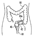
- the overtube 40 is extrapolated to the insertion portion 2, and the overtube 40 is drawn to the proximal end 10 b side (the operation portion 3 side) of the flexible tube portion 10. That is, the overtube 40 is located outside the anus 61.
- the range in which the hardness change mechanism unit 20 does not raise the hardness of the flexible tube portion 10 is not performed in the range inserted in the large intestine 60 of the insertion portion 2 and the overtube 40 It is the softest state with the lowest hardness because it is not broken. Therefore, the insertion portion 2 can be easily advanced in the bent S-shaped colon 60a.
- the overtube 40 is moved along the insertion portion 2 in the distal direction, and the tip of the overtube 40 reaches the S-shaped colon 60a.
- the overtube 40 is positioned on the tip side of the tip of the hardness change mechanism 20.
- a gas is sent from the balloon vent 43 into the balloon 42 to inflate the balloon 42 and fix the position of the overtube 40.
- the S-shaped colon 60a is linearized by pulling the overtube 40 whose position is fixed and the insertion portion 2 whose hardness is increased. Further, the hardness of the flexible tube portion 10 is increased by the hardness change mechanism portion 20.
- the insertion portion 2 on which the hardness increase operation has been performed is pushed in, and the distal end of the insertion portion 2 is the descending colon 60b and the transverse colon 60c. Advance to splenic curvature 60d between.
- the hardness of the insertion portion 2 is in a state of rising with a gradual change from the distal end toward the proximal end. That is, the distal end side of the insertion portion 2 with low hardness can be easily advanced while maintaining the hardness of the proximal end portion of the insertion portion 2 inserted into the straightened S-shaped colon 60a. .
- the distal end of the insertion portion 2 is advanced into the transverse colon 60c.
- the overtube 40 is moved in the distal direction along the insertion portion 2 to advance the tip of the overtube 40 to the splenic curve 60d Let And it is set as the state which does not raise operation of hardness of flexible tube part 10 by hardness change mechanism part 20.
- the hardness of the flexible tube portion 10 is increased by the presence of the overtube 40, even if the hardness increasing operation by the hardness changing mechanism portion 20 is not performed.
- the shape of the linearized sigmoid colon 60a is maintained.
- the position of the overtube 40 is fixed while the hardness changing operation of the hardness changing unit 20 is not performed.
- Only the insertion portion 2 is advanced until the tip reaches the liver curvature 60e.
- the shape of the S-shaped colon 60a linearized by the hardness of the overtube 40 is maintained, and the range inserted in the large intestine 60 of the insertion portion 2 is the flexible tube portion 10 by the hardness change mechanism portion 20.
- the insertion portion can be easily inserted even in the transverse colon 60c in which a large amount of bending is not fixed because the operation of increasing the hardness of the lower hardness is not performed and the softest state where the hardness is not covered by the overtube 40 is low. 2 can be progressed (if it remains rigid, the inflection of the transverse colon drops largely on the anal side, making insertion difficult).
- the hardness change operation of the flexible tube 10 by the hardness change mechanism 20 is performed to lift the transverse colon 60c.
- the overtube 40 is moved in the distal direction along the insertion portion 2 to advance the tip of the overtube 40 to the liver curvature 60e, and then the balloon 42 is inflated to fix the position of the overtube 40.
- the shapes of the straightened S-shaped colon 60a and the lifted transverse colon 60c are maintained, so the insertion portion 2 is further advanced as far as the colon.
- the operation to progress to the colon 60 f is facilitated.
- the hardness change mechanism unit 20 switches the presence or absence of the operation of increasing the hardness of the flexible tube 10 and the overtube 40 to the insertion unit 2.
- the hardness change mechanism unit 20 switches the presence or absence of the operation of increasing the hardness of the flexible tube 10 and the overtube 40 to the insertion unit 2.
- the large diameter portion 10c having an outer diameter larger than the outer diameter of the flexible tube portion 10 is provided at a position corresponding to the tip portion of the hardness change region in the flexible tube portion 10 as the notification means.
- the proximal end 41b of the overtube 40 is positioned when the distal end 41a of the overtube 40 is on the distal end of the hardness change region on the proximal end side of the flexible tube 10
- An index may be provided on the part. This indicator is always located outside the patient's body, so it can be easily viewed by the operator.
Landscapes
- Health & Medical Sciences (AREA)
- Life Sciences & Earth Sciences (AREA)
- Surgery (AREA)
- Biomedical Technology (AREA)
- Medical Informatics (AREA)
- Optics & Photonics (AREA)
- Pathology (AREA)
- Radiology & Medical Imaging (AREA)
- Biophysics (AREA)
- Engineering & Computer Science (AREA)
- Physics & Mathematics (AREA)
- Heart & Thoracic Surgery (AREA)
- Nuclear Medicine, Radiotherapy & Molecular Imaging (AREA)
- Molecular Biology (AREA)
- Animal Behavior & Ethology (AREA)
- General Health & Medical Sciences (AREA)
- Public Health (AREA)
- Veterinary Medicine (AREA)
- Endoscopes (AREA)
- Instruments For Viewing The Inside Of Hollow Bodies (AREA)
Abstract
La présente invention concerne un endoscope qui comprend : une partie d'insertion allongée; une partie de tube flexible qui forme un côté d'extrémité proximale de la partie d'insertion; un mécanisme de changement de rigidité qui est disposé à l'intérieur du tube de la partie de tube flexible et qui est destiné à modifier la rigidité de la partie de tube flexible lors du fonctionnement sur le côté utilisateur; et une partie de grand diamètre qui est disposée sur la circonférence extérieure de la partie de tube flexible et indique, sur la partie de tube flexible, l'extrémité distale d'une région de rigidité variable de celle-ci qui est commandée par le mécanisme de changement de rigidité.
Priority Applications (3)
| Application Number | Priority Date | Filing Date | Title |
|---|---|---|---|
| CN201880080891.2A CN111479493B (zh) | 2017-12-28 | 2018-08-06 | 内窥镜及内窥镜系统 |
| JP2019562732A JP6751824B2 (ja) | 2017-12-28 | 2018-08-06 | 内視鏡及び内視鏡システム |
| US16/911,454 US20200323421A1 (en) | 2017-12-28 | 2020-06-25 | Endoscope and endoscope system |
Applications Claiming Priority (2)
| Application Number | Priority Date | Filing Date | Title |
|---|---|---|---|
| JP2017253118 | 2017-12-28 | ||
| JP2017-253118 | 2017-12-28 |
Related Child Applications (1)
| Application Number | Title | Priority Date | Filing Date |
|---|---|---|---|
| US16/911,454 Continuation US20200323421A1 (en) | 2017-12-28 | 2020-06-25 | Endoscope and endoscope system |
Publications (1)
| Publication Number | Publication Date |
|---|---|
| WO2019130639A1 true WO2019130639A1 (fr) | 2019-07-04 |
Family
ID=67063030
Family Applications (1)
| Application Number | Title | Priority Date | Filing Date |
|---|---|---|---|
| PCT/JP2018/029376 WO2019130639A1 (fr) | 2017-12-28 | 2018-08-06 | Endoscope et système d'endoscope |
Country Status (4)
| Country | Link |
|---|---|
| US (1) | US20200323421A1 (fr) |
| JP (1) | JP6751824B2 (fr) |
| CN (1) | CN111479493B (fr) |
| WO (1) | WO2019130639A1 (fr) |
Families Citing this family (3)
| Publication number | Priority date | Publication date | Assignee | Title |
|---|---|---|---|---|
| CN110325098A (zh) | 2016-11-28 | 2019-10-11 | 适内有限责任公司 | 具有可分离一次性轴的内窥镜 |
| USD1018844S1 (en) | 2020-01-09 | 2024-03-19 | Adaptivendo Llc | Endoscope handle |
| CN116369829B (zh) * | 2023-06-06 | 2023-09-08 | 新光维医疗科技(苏州)股份有限公司 | 内窥镜、成像系统及内窥镜控制方式 |
Citations (3)
| Publication number | Priority date | Publication date | Assignee | Title |
|---|---|---|---|---|
| JPH1189790A (ja) * | 1997-09-25 | 1999-04-06 | Olympus Optical Co Ltd | 内視鏡装置 |
| JP2012070854A (ja) * | 2010-09-28 | 2012-04-12 | Hoya Corp | 手術用内視鏡装置 |
| WO2017086312A1 (fr) * | 2015-11-20 | 2017-05-26 | オリンパス株式会社 | Système d'endoscope |
Family Cites Families (18)
| Publication number | Priority date | Publication date | Assignee | Title |
|---|---|---|---|---|
| JPH05285090A (ja) * | 1992-04-13 | 1993-11-02 | Asahi Optical Co Ltd | 内視鏡における湾曲部被覆チューブの装着方法 |
| US5885208A (en) * | 1996-12-24 | 1999-03-23 | Olympus Optical Co., Ltd. | Endoscope system |
| JP3776557B2 (ja) * | 1997-04-10 | 2006-05-17 | オリンパス株式会社 | 内視鏡 |
| JP3969678B2 (ja) * | 1997-05-01 | 2007-09-05 | 幸士 生田 | 剛性可変型索状体 |
| JP4629213B2 (ja) * | 2000-11-24 | 2011-02-09 | Hoya株式会社 | 内視鏡の外装チューブ装着構造及び内視鏡の外装チューブ装着方法 |
| JP4681752B2 (ja) * | 2001-05-08 | 2011-05-11 | Hoya株式会社 | 内視鏡の曲げ剛性調整具 |
| JP4772208B2 (ja) * | 2001-05-10 | 2011-09-14 | オリンパス株式会社 | 内視鏡 |
| JP2002360504A (ja) * | 2001-06-04 | 2002-12-17 | Pentax Corp | 可撓性可変内視鏡 |
| JP4172966B2 (ja) * | 2002-08-08 | 2008-10-29 | Hoya株式会社 | 内視鏡の硬度可変シースアダプタ |
| JP3864344B2 (ja) * | 2003-12-05 | 2006-12-27 | フジノン株式会社 | 内視鏡の挿入補助具 |
| JP2005237817A (ja) * | 2004-02-27 | 2005-09-08 | Olympus Corp | 内視鏡 |
| JP4323441B2 (ja) * | 2005-02-14 | 2009-09-02 | オリンパス株式会社 | 内視鏡 |
| JP2008035909A (ja) * | 2006-08-01 | 2008-02-21 | Olympus Medical Systems Corp | 内視鏡用挿入補助具 |
| JP5810037B2 (ja) * | 2012-06-04 | 2015-11-11 | オリンパス株式会社 | 内視鏡システム |
| JP5711434B1 (ja) * | 2013-08-30 | 2015-04-30 | オリンパスメディカルシステムズ株式会社 | 内視鏡 |
| JP6419219B2 (ja) * | 2015-01-28 | 2018-11-07 | オリンパス株式会社 | 可撓管挿入装置 |
| JP2016187382A (ja) * | 2015-03-30 | 2016-11-04 | Hoya株式会社 | 内視鏡挿入部の先端部接続構造 |
| JP6444809B2 (ja) * | 2015-06-05 | 2018-12-26 | 富士フイルム株式会社 | 内視鏡システム |
-
2018
- 2018-08-06 CN CN201880080891.2A patent/CN111479493B/zh active Active
- 2018-08-06 JP JP2019562732A patent/JP6751824B2/ja active Active
- 2018-08-06 WO PCT/JP2018/029376 patent/WO2019130639A1/fr active Application Filing
-
2020
- 2020-06-25 US US16/911,454 patent/US20200323421A1/en not_active Abandoned
Patent Citations (3)
| Publication number | Priority date | Publication date | Assignee | Title |
|---|---|---|---|---|
| JPH1189790A (ja) * | 1997-09-25 | 1999-04-06 | Olympus Optical Co Ltd | 内視鏡装置 |
| JP2012070854A (ja) * | 2010-09-28 | 2012-04-12 | Hoya Corp | 手術用内視鏡装置 |
| WO2017086312A1 (fr) * | 2015-11-20 | 2017-05-26 | オリンパス株式会社 | Système d'endoscope |
Also Published As
| Publication number | Publication date |
|---|---|
| JP6751824B2 (ja) | 2020-09-09 |
| CN111479493A (zh) | 2020-07-31 |
| JPWO2019130639A1 (ja) | 2020-09-03 |
| US20200323421A1 (en) | 2020-10-15 |
| CN111479493B (zh) | 2023-04-25 |
Similar Documents
| Publication | Publication Date | Title |
|---|---|---|
| JP6423539B2 (ja) | 内視鏡システム | |
| JP4637903B2 (ja) | 内視鏡システム | |
| JP5245138B2 (ja) | 内視鏡 | |
| CA2898586C (fr) | Dispositif de direction integre | |
| JP5917467B2 (ja) | 内視鏡 | |
| US20200323421A1 (en) | Endoscope and endoscope system | |
| CN107405045B (zh) | 挠性管插入装置 | |
| US10485410B2 (en) | Flexible tube insertion apparatus | |
| JP6444809B2 (ja) | 内視鏡システム | |
| US9872607B2 (en) | Endoscope | |
| US10156304B2 (en) | Flexible tube and insertion device | |
| JP3923701B2 (ja) | 内視鏡 | |
| WO2018122976A1 (fr) | Appareil d'insertion de tuyau flexible | |
| JP6203455B1 (ja) | 内視鏡システム | |
| JP3934593B2 (ja) | 内視鏡システム | |
| JP5161420B2 (ja) | 内視鏡の挿入部 | |
| EP3260034A1 (fr) | Système d'endoscope | |
| JP5996307B2 (ja) | 内視鏡 | |
| JP2010035759A (ja) | 内視鏡 | |
| JP5797363B1 (ja) | 内視鏡に用いられるコイル構造、このコイル構造を備えた内視鏡および処置具 | |
| JPH0445177B2 (fr) | ||
| WO2017109987A1 (fr) | Appareil d'insertion de tube flexible | |
| JP2005279124A (ja) | 内視鏡の湾曲装置 | |
| JP2018175225A (ja) | 内視鏡システム |
Legal Events
| Date | Code | Title | Description |
|---|---|---|---|
| 121 | Ep: the epo has been informed by wipo that ep was designated in this application |
Ref document number: 18895535 Country of ref document: EP Kind code of ref document: A1 |
|
| ENP | Entry into the national phase |
Ref document number: 2019562732 Country of ref document: JP Kind code of ref document: A |
|
| NENP | Non-entry into the national phase |
Ref country code: DE |
|
| 122 | Ep: pct application non-entry in european phase |
Ref document number: 18895535 Country of ref document: EP Kind code of ref document: A1 |