WO2019112042A1 - 基板処理装置、基板処理方法及び基板処理方法を実行させるプログラムが記録された記憶媒体 - Google Patents
基板処理装置、基板処理方法及び基板処理方法を実行させるプログラムが記録された記憶媒体 Download PDFInfo
- Publication number
- WO2019112042A1 WO2019112042A1 PCT/JP2018/045099 JP2018045099W WO2019112042A1 WO 2019112042 A1 WO2019112042 A1 WO 2019112042A1 JP 2018045099 W JP2018045099 W JP 2018045099W WO 2019112042 A1 WO2019112042 A1 WO 2019112042A1
- Authority
- WO
- WIPO (PCT)
- Prior art keywords
- substrate
- processing
- film
- unit
- substrate processing
- Prior art date
- Legal status (The legal status is an assumption and is not a legal conclusion. Google has not performed a legal analysis and makes no representation as to the accuracy of the status listed.)
- Ceased
Links
Images





Classifications
-
- H—ELECTRICITY
- H10—SEMICONDUCTOR DEVICES; ELECTRIC SOLID-STATE DEVICES NOT OTHERWISE PROVIDED FOR
- H10P—GENERIC PROCESSES OR APPARATUS FOR THE MANUFACTURE OR TREATMENT OF DEVICES COVERED BY CLASS H10
- H10P50/00—Etching of wafers, substrates or parts of devices
- H10P50/20—Dry etching; Plasma etching; Reactive-ion etching
- H10P50/28—Dry etching; Plasma etching; Reactive-ion etching of insulating materials
- H10P50/282—Dry etching; Plasma etching; Reactive-ion etching of insulating materials of inorganic materials
- H10P50/283—Dry etching; Plasma etching; Reactive-ion etching of insulating materials of inorganic materials by chemical means
-
- B—PERFORMING OPERATIONS; TRANSPORTING
- B08—CLEANING
- B08B—CLEANING IN GENERAL; PREVENTION OF FOULING IN GENERAL
- B08B3/00—Cleaning by methods involving the use or presence of liquid or steam
- B08B3/02—Cleaning by the force of jets or sprays
-
- H—ELECTRICITY
- H10—SEMICONDUCTOR DEVICES; ELECTRIC SOLID-STATE DEVICES NOT OTHERWISE PROVIDED FOR
- H10P—GENERIC PROCESSES OR APPARATUS FOR THE MANUFACTURE OR TREATMENT OF DEVICES COVERED BY CLASS H10
- H10P14/00—Formation of materials, e.g. in the shape of layers or pillars
- H10P14/60—Formation of materials, e.g. in the shape of layers or pillars of insulating materials
- H10P14/68—Organic materials, e.g. photoresists
- H10P14/683—Organic materials, e.g. photoresists carbon-based polymeric organic materials, e.g. polyimides, poly cyclobutene or PVC
-
- H—ELECTRICITY
- H10—SEMICONDUCTOR DEVICES; ELECTRIC SOLID-STATE DEVICES NOT OTHERWISE PROVIDED FOR
- H10P—GENERIC PROCESSES OR APPARATUS FOR THE MANUFACTURE OR TREATMENT OF DEVICES COVERED BY CLASS H10
- H10P50/00—Etching of wafers, substrates or parts of devices
- H10P50/20—Dry etching; Plasma etching; Reactive-ion etching
- H10P50/26—Dry etching; Plasma etching; Reactive-ion etching of conductive or resistive materials
- H10P50/264—Dry etching; Plasma etching; Reactive-ion etching of conductive or resistive materials by chemical means
- H10P50/266—Dry etching; Plasma etching; Reactive-ion etching of conductive or resistive materials by chemical means by vapour etching only
- H10P50/269—Dry etching; Plasma etching; Reactive-ion etching of conductive or resistive materials by chemical means by vapour etching only pre- or post-treatments, e.g. anti-corrosion processes
-
- H—ELECTRICITY
- H10—SEMICONDUCTOR DEVICES; ELECTRIC SOLID-STATE DEVICES NOT OTHERWISE PROVIDED FOR
- H10P—GENERIC PROCESSES OR APPARATUS FOR THE MANUFACTURE OR TREATMENT OF DEVICES COVERED BY CLASS H10
- H10P50/00—Etching of wafers, substrates or parts of devices
- H10P50/71—Etching of wafers, substrates or parts of devices using masks for conductive or resistive materials
-
- H—ELECTRICITY
- H10—SEMICONDUCTOR DEVICES; ELECTRIC SOLID-STATE DEVICES NOT OTHERWISE PROVIDED FOR
- H10P—GENERIC PROCESSES OR APPARATUS FOR THE MANUFACTURE OR TREATMENT OF DEVICES COVERED BY CLASS H10
- H10P70/00—Cleaning of wafers, substrates or parts of devices
- H10P70/20—Cleaning during device manufacture
- H10P70/23—Cleaning during device manufacture during, before or after processing of insulating materials
- H10P70/234—Cleaning during device manufacture during, before or after processing of insulating materials the processing being the formation of vias or contact holes
-
- H—ELECTRICITY
- H10—SEMICONDUCTOR DEVICES; ELECTRIC SOLID-STATE DEVICES NOT OTHERWISE PROVIDED FOR
- H10P—GENERIC PROCESSES OR APPARATUS FOR THE MANUFACTURE OR TREATMENT OF DEVICES COVERED BY CLASS H10
- H10P70/00—Cleaning of wafers, substrates or parts of devices
- H10P70/20—Cleaning during device manufacture
- H10P70/27—Cleaning during device manufacture during, before or after processing of conductive materials, e.g. polysilicon or amorphous silicon layers
- H10P70/273—Cleaning during device manufacture during, before or after processing of conductive materials, e.g. polysilicon or amorphous silicon layers the processing being a delineation of conductive layers, e.g. by RIE
-
- H—ELECTRICITY
- H10—SEMICONDUCTOR DEVICES; ELECTRIC SOLID-STATE DEVICES NOT OTHERWISE PROVIDED FOR
- H10P—GENERIC PROCESSES OR APPARATUS FOR THE MANUFACTURE OR TREATMENT OF DEVICES COVERED BY CLASS H10
- H10P72/00—Handling or holding of wafers, substrates or devices during manufacture or treatment thereof
- H10P72/04—Apparatus for manufacture or treatment
- H10P72/0402—Apparatus for fluid treatment
- H10P72/0406—Apparatus for fluid treatment for cleaning followed by drying, rinsing, stripping, blasting or the like
- H10P72/0411—Apparatus for fluid treatment for cleaning followed by drying, rinsing, stripping, blasting or the like for wet cleaning or washing
- H10P72/0414—Apparatus for fluid treatment for cleaning followed by drying, rinsing, stripping, blasting or the like for wet cleaning or washing using mainly spraying means, e.g. nozzles
-
- H—ELECTRICITY
- H10—SEMICONDUCTOR DEVICES; ELECTRIC SOLID-STATE DEVICES NOT OTHERWISE PROVIDED FOR
- H10P—GENERIC PROCESSES OR APPARATUS FOR THE MANUFACTURE OR TREATMENT OF DEVICES COVERED BY CLASS H10
- H10P72/00—Handling or holding of wafers, substrates or devices during manufacture or treatment thereof
- H10P72/04—Apparatus for manufacture or treatment
- H10P72/0431—Apparatus for thermal treatment
- H10P72/0436—Apparatus for thermal treatment mainly by radiation
-
- H—ELECTRICITY
- H10—SEMICONDUCTOR DEVICES; ELECTRIC SOLID-STATE DEVICES NOT OTHERWISE PROVIDED FOR
- H10P—GENERIC PROCESSES OR APPARATUS FOR THE MANUFACTURE OR TREATMENT OF DEVICES COVERED BY CLASS H10
- H10P72/00—Handling or holding of wafers, substrates or devices during manufacture or treatment thereof
- H10P72/04—Apparatus for manufacture or treatment
- H10P72/0448—Apparatus for applying a liquid, a resin, an ink or the like
-
- H—ELECTRICITY
- H10—SEMICONDUCTOR DEVICES; ELECTRIC SOLID-STATE DEVICES NOT OTHERWISE PROVIDED FOR
- H10P—GENERIC PROCESSES OR APPARATUS FOR THE MANUFACTURE OR TREATMENT OF DEVICES COVERED BY CLASS H10
- H10P76/00—Manufacture or treatment of masks on semiconductor bodies, e.g. by lithography or photolithography
- H10P76/40—Manufacture or treatment of masks on semiconductor bodies, e.g. by lithography or photolithography of masks comprising inorganic materials
- H10P76/408—Manufacture or treatment of masks on semiconductor bodies, e.g. by lithography or photolithography of masks comprising inorganic materials characterised by their sizes, orientations, dispositions, behaviours or shapes
- H10P76/4085—Manufacture or treatment of masks on semiconductor bodies, e.g. by lithography or photolithography of masks comprising inorganic materials characterised by their sizes, orientations, dispositions, behaviours or shapes characterised by the processes involved to create the masks
Definitions
- the present invention relates to a substrate processing apparatus and a substrate processing method for removing deposits on the substrate from a substrate, and a storage medium storing a program for executing the substrate processing method.
- a film to be etched (for example, an interlayer insulating film, a metal film, etc.) formed on a substrate such as a semiconductor wafer is etched using a resist film as a mask material and patterned into a predetermined pattern Process is performed.
- Low-k film low dielectric constant film
- a dual damascene method is employed in which holes are formed and Cu is embedded therein.
- Organic low-k films are often used, and when etching such organic low-k films, the selectivity with the resist film which is the same organic film can not be sufficiently obtained.
- An inorganic hard mask film such as a Ti film or a TiN film is used as a mask material for etching. That is, the hard mask film is etched to a predetermined pattern using the resist film as a mask material, and the low-k film is etched using the hard mask film etched to a predetermined pattern as a mask material.
- the removal of these unnecessary deposits can be performed, for example, by continuously supplying a removal solution to the center of a semiconductor wafer as a substrate to be processed using a single-wafer cleaning apparatus, and using centrifugal force. The removal is performed while spreading the removal solution on the entire surface of the semiconductor wafer (for example, Patent Document 1, Patent Document 2, Patent Document 3).
- An object of the present invention is to provide a technique capable of effectively removing deposits (for example, a resist film, a hard coat film, etc.) on a substrate from the substrate.
- deposits for example, a resist film, a hard coat film, etc.
- a substrate processing apparatus for removing a deposit on a substrate from a substrate, wherein the substrate has a remover for the deposit and a boiling point lower than the boiling point of the remover.
- a first processing liquid supply unit for supplying a first processing liquid containing a solvent having a thickener and a thickener, and a second for forming a gas diffusion preventing film on a substrate to which the first processing liquid is supplied
- a second processing liquid supply unit that supplies the processing liquid; a substrate heating unit that heats the substrate to which the second processing liquid is supplied at a predetermined temperature that is higher than the boiling point of the solvent and lower than the boiling temperature of the removal agent;
- a removal processing unit having a rinse liquid supply unit for supplying a rinse liquid, and the first processing liquid supply unit supplies the first processing liquid to the substrate, and then the second processing liquid supply unit is the substrate Supply the second processing liquid to the substrate, and then the substrate heating unit The heating is performed at a constant temperature, which promotes the evaporation of the
- a control unit configured to control the first processing liquid supply unit, the second processing liquid supply unit, the substrate heating unit, and the rinse liquid supply unit so as to remove the deposit from the substrate;
- a substrate processing apparatus is provided, wherein the diffusion prevention film prevents the gaseous reactive product generated by the reaction of the deposit and the removing agent from diffusing around the substrate.
- a substrate processing method for removing a deposit on a substrate from a substrate comprising: (A) a remover for the deposit and a boiling point of the remover on the substrate. Supplying a first processing solution containing a solvent having a lower boiling point and a thickener, and (B) after step (A), the substrate contains an organic polymer to be a gas diffusion preventing film And (C) after the step (B), the substrate is heated at a predetermined temperature not lower than the boiling point of the solvent and lower than the boiling point of the remover, to evaporate the solvent, and And (D) supplying a rinse liquid to the substrate after the step (C) to remove the deposit from the substrate.
- the gas diffusion preventing film is a reaction of the deposit and the removing agent in the step (C). More resulting gaseous reactive product is prevented from diffusing around the substrate, the substrate processing method is provided.
- a program that, when executed by a computer for controlling the operation of a substrate processing apparatus, the computer controls the substrate processing apparatus to execute the substrate processing method.
- a recorded storage medium is provided.
- the deposit for example, resist film, hard coat film, etc.
- the deposit can be effectively removed from the substrate.
- gas diffusion preventing film when the substrate is heated, gaseous reactive products generated by the reaction of the deposit and the removing agent diffuse through the gas diffusion preventing film around the substrate. Therefore, even if the gaseous reactive product is corrosive, the reactive product may damage the components of the processing apparatus or particles from the reactive product may be generated. Can be prevented.
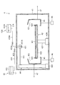
- FIG. 1 is a schematic view showing the configuration of a substrate processing apparatus according to an embodiment of the present invention.
- FIG. 2 is a schematic plan view showing the configuration of a substrate processing unit provided in the substrate processing apparatus shown in FIG.
- FIG. 3 is a schematic cross-sectional view showing a configuration of a first processing unit provided in the substrate processing unit shown in FIG.
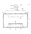
- FIG. 4 is a schematic cross-sectional view showing a configuration of a second processing unit provided in the substrate processing unit shown in FIG.
- FIG. 5 is a schematic cross-sectional view showing a configuration of a third processing unit provided in the substrate processing unit shown in FIG.
- FIG. 6 is a schematic cross-sectional view for explaining the dry etching process.
- FIG. 1 is a schematic view showing the configuration of a substrate processing apparatus according to an embodiment of the present invention.
- FIG. 2 is a schematic plan view showing the configuration of a substrate processing unit provided in the substrate processing apparatus shown in FIG.
- FIG. 3 is a schematic cross-sectional view showing
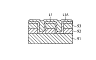
- FIG. 7 is a schematic cross-sectional view for explaining the state of the film obtained by supplying the first treatment liquid.
- FIG. 8 is a schematic cross-sectional view for explaining the state of the film obtained by supplying the second treatment liquid onto the film with the first treatment liquid. It is the schematic explaining the method to remove the hard mask of a board
- FIG. 1 is a schematic view showing the configuration of a substrate processing apparatus according to an embodiment of the present invention.
- a substrate processing apparatus 1 includes a substrate processing unit 2 and a control unit 3 that controls the operation of the substrate processing unit 2.
- the substrate processing unit 2 performs various types of processing on a substrate. The various processes performed by the substrate processing unit 2 will be described later.
- the control unit 3 is, for example, a computer, and includes a control unit and a storage unit.
- the control unit is, for example, a central processing unit (CPU), and controls the operation of the substrate processing unit 2 by reading and executing a program stored in the storage unit.
- the storage unit is composed of, for example, a storage device such as a random access memory (RAM), a read only memory (ROM), or a hard disk, and stores a program for controlling various processes executed in the substrate processing unit 2.
- the program may be recorded on a computer-readable storage medium, or may be installed from the storage medium to the storage unit. Examples of the computer-readable storage medium include a hard disk (HD), a flexible disk (FD), a compact disk (CD), a magnet optical disk (MO), and a memory card.
- a program that causes the computer to control the substrate processing apparatus 1 to execute a substrate processing method which will be described later, is recorded on the recording medium, when executed by a computer for controlling the operation of the substrate processing apparatus 1.
- FIG. 2 is a schematic plan view showing the configuration of the substrate processing unit 2.
- the dotted line in FIG. 2 represents a substrate.
- the substrate processing unit 2 performs various types of processing on a substrate.
- the substrate processing unit 2 performs a removal process for removing the hard mask film on the substrate after the dry etching process.
- the process performed by the substrate processing unit 2 is not particularly limited as long as it includes the process of removing the hard mask film on the substrate from the substrate.
- the processing performed by the substrate processing unit 2 may include other processing.
- the hard mask film on the substrate after dry etching is the removal target, but the hard mask film is an example of the deposit on the substrate.
- the deposit on the substrate include an unnecessary organic film, an inorganic film, an organic-inorganic composite film (eg, a resist film, an antireflective film, etc.) remaining on the substrate after dry etching, and an etching process.
- By-products eg, polymers derived from etching gas, resist film, hard mask film, etc.
- resist residues generated during ashing of the resist film are not limited to the deposit on the substrate after dry etching, and may be, for example, a cured resist layer after ion implantation.
- the substrate processing unit 2 includes a loading and unloading station 21 and a processing station 22 provided adjacent to the loading and unloading station 21.
- the loading / unloading station 21 includes a placement unit 211 and a transport unit 212 provided adjacent to the placement unit 211.
- carriers C accommodating the plurality of substrates in a horizontal state are placed.
- the transport unit 212 includes a transport mechanism 213 and a delivery unit 214.
- the transport mechanism 213 is provided with a holding mechanism for holding a substrate, and is configured to be able to move in the horizontal direction and the vertical direction and to turn around the vertical axis.
- the processing station 22 includes a first processing unit 4 that supplies the processing liquid to the substrate, a second processing unit 5 that heats the substrate to which the processing liquid has been supplied by the first processing unit 4, and a second processing unit 5.
- the third processing unit 6 supplies the rinse liquid to the substrate heated by the processing unit 5.
- the number of first processing units 4 included in the processing station 22 is two or more, but may be one. The same applies to the second processing unit 5 and the third processing unit 6.
- the first processing unit 4 is arranged on one side of the transport path 221 extending in a predetermined direction
- the second processing unit 5 is arranged on the other side of the transport path 221.
- the third processing units 6 are arranged on both sides of the transport path 221.
- the arrangement of the present embodiment is an example, and the arrangement of the first to third processing units may be arbitrarily determined according to the design, the operation reason, and the like.
- the transport mechanism 222 includes a holding mechanism that holds the substrate, and is configured to be able to move in the horizontal direction and the vertical direction and to pivot around the vertical axis.
- the substrate before the first processing liquid 4 is supplied with the first processing liquid L1 and the second processing liquid L1A is referred to as “substrate W1”, and the first processing liquid 4 includes the first processing liquid L1 and the second processing liquid L1A.
- the substrate before being heated in the second processing unit 5 is “substrate W 2”, and after being heated in the second processing unit 5, the rinse liquid L 2 is supplied in the third processing unit 6.
- the substrate before the process is referred to as "substrate W3”
- the substrate after the rinse liquid L2 is supplied by the third processing unit 6 is referred to as "the substrate W4".
- the transport mechanism 213 of the loading / unloading station 21 transports the substrates W 1 and W 4 between the carrier C and the delivery unit 214. Specifically, the transport mechanism 213 takes out the substrate W1 from the carrier C placed on the placement unit 211, and places the taken-out substrate W1 on the delivery unit 214. Further, the transport mechanism 213 takes out the substrate W4 placed on the delivery unit 214 by the transport mechanism 222 of the processing station 22 and stores the substrate W4 in the carrier C of the placement unit 211.
- the transport mechanism 222 of the processing station 22 is between the delivery unit 214 and the first processing unit 4, between the first processing unit 4 and the second processing unit 5, the second processing unit 5 and the second processing unit 5.
- the substrates W 1 to W 4 are transported to and from the third processing unit 6 and between the third processing unit 6 and the delivery unit 214.
- the transport mechanism 222 takes out the substrate W1 placed on the delivery unit 214 and carries the taken-out substrate W1 into the first processing unit 4.
- the transport mechanism 222 takes out the substrate W2 from the first processing unit 4 and carries the taken out substrate W2 into the second processing unit 5.
- the transport mechanism 222 takes out the substrate W3 from the second processing unit 5 and carries the taken-out substrate W3 into the third processing unit 6.
- the transport mechanism 222 takes out the substrate W4 from the third processing unit 6, and places the taken-out substrate W4 on the delivery unit 214.
- FIG. 3 is a schematic cross-sectional view showing the configuration of the first processing unit 4.
- the first processing unit 4 performs processing including supply of a processing liquid to the substrate W1. Other processes may be included in the process performed by the first processing unit 4.
- the substrate W1 is a substrate after the dry etching process, and has a concavo-convex pattern on the surface.
- An example of the structure of the substrate W1 is shown in FIG.
- the substrate W1 has, for example, a semiconductor wafer 91, a to-be-etched film 92, and a hard mask film 93 in order.
- the to-be-etched film 92 and the hard mask film 93 are patterned into a predetermined pattern by dry etching, and form a concavo-convex pattern on the surface of the substrate W1.
- the semiconductor wafer 91 is, for example, a silicon wafer.
- the film to be etched 92 is, for example, an insulating film, a conductor film, or the like.
- the insulating film is, for example, a silicon-based insulating film such as a SiO 2 film or a low dielectric constant film called a low-k film.
- the low-k film is, for example, a film whose relative dielectric constant is lower than that of silicon dioxide, such as a SiOC film, a SiCOH film or the like.
- the conductor film is, for example, a metal film such as a Cu film or an Al film.
- the hard mask film 93 is, for example, an inorganic hard mask film, an organic hard mask film, an organic-inorganic composite hard mask film, or the like.
- Examples of the inorganic material constituting the inorganic hard mask film include titanium (Ti), titanium nitride (TiN), silicon oxide (SiO 2 ), silicon nitride (Si 3 N 4 ), and silicon oxynitride (SiON). , Silicon nitride (SiN), silicon carbide (SiC), silicon carbonitride (SiCN), and the like.
- organic material which comprises an organic hard mask film
- organic-inorganic composite material constituting the organic-inorganic hard mask film examples include polycarbosilane, organopolysilazane, organopolysilane, copolymer of polysiloxane and metal oxide (titanium oxide, aluminum oxide, tungsten oxide) Etc.
- the substrate W1 is obtained, for example, by the dry etching process of the raw material substrate W0 shown in FIG.
- the raw material substrate W0 has a semiconductor wafer 91, a film 92 to be etched, a hard mask film 93 ', and a photoresist film 94 patterned in a predetermined pattern by a photolithography process in order.
- the to-be-etched film 92 'and the hard mask film 93' are not yet patterned in a predetermined pattern.
- the dry etching process of the raw material substrate W0 is performed, for example, as follows. First, as shown in FIG. 6B, the hard mask film 93 'is dry etched using the photoresist film 94 as a mask material. Thereby, the pattern of the photoresist film 94 is transferred to the hard mask film 93 ', and the hard mask film 93 patterned in a predetermined pattern is formed.
- the photoresist film 94 is removed by ashing.
- the film to be etched 92 ' is dry etched using the hard mask film 93 as a mask material.
- an etching target film 92 patterned in a predetermined pattern is formed.
- the dry etching process may be anisotropic etching or may be isotropic etching.
- Examples of the etching method used in the dry etching process include ECR etching method, ICP etching method, CCP etching method, Helicon etching method, TCP etching method, UHF plasma method, SWP etching method and the like.
- the substrate W1 is generated during ashing of a resist film, a by-product generated during etching (for example, a polymer derived from an etching gas, a resist film, a hard mask film, etc.)
- Substance P such as resist residue may be adhered.
- the first processing unit 4 includes a chamber 41, and performs substrate processing including supply of a processing liquid in the chamber 41.
- the first processing unit 4 includes a substrate holding unit 42.
- the substrate holding unit 42 is provided on the outer periphery of the upper surface of the rotary shaft 421 extending in the vertical direction in the chamber 41, the turntable 422 attached to the upper end of the rotary shaft 421, and the turntable 422.
- a chuck 423 for supporting the outer edge portion and a drive unit 424 for rotationally driving the rotation shaft 421 are provided, and the substrate W1 can be held and rotated.
- the substrate W1 is supported by the chuck 423 and held horizontally by the turntable 422 in a state slightly separated from the upper surface of the turntable 422.
- the holding method of the substrate W1 by the substrate holding unit 42 is a so-called mechanical chuck type in which the outer edge portion of the substrate W1 is gripped by the movable chuck 423, but a so-called vacuum which vacuum-sucks the back surface of the substrate W1. It may be of a chuck type.
- the proximal end of the rotation shaft 421 is rotatably supported by the drive unit 424, and the tip of the rotation shaft 421 supports the turntable 422 horizontally.
- the control unit 3 controls the operation of the drive unit 424, and controls the rotation timing, the rotation speed, and the like of the substrate W1.
- the first processing unit 4 includes a first processing liquid supply unit 43 that supplies the first processing liquid L1 to the substrate W1 held by the substrate holding unit 42.
- the first processing liquid supply unit 43 supplies the first processing liquid L1 to the nozzle 431 and the nozzle 431 that discharges the first processing liquid L1 to the substrate W1 held by the substrate holding unit 42. And 432.
- the first processing liquid L 1 is stored in a tank of the processing liquid supply source 432, and a supply conduit 434 in which a flow rate adjuster such as a valve 433 is interposed in the nozzle 431 from the processing liquid supply source 432. Through which the first processing liquid L1 is supplied.
- the first processing unit 4 may include a plurality of processing liquid supply units that supply different processing liquids.
- the additional treatment liquid supply unit can be configured in the same manner as the first treatment liquid supply unit 43.
- the first treatment liquid L1 contains a remover for the hard mask film 93 (hereinafter sometimes simply referred to as “remover”), a solvent having a boiling point lower than that of the remover, and a thickener.
- a remover for the hard mask film 93 hereinafter sometimes simply referred to as “remover”
- a solvent having a boiling point lower than that of the remover and a thickener.
- the removal agent for the hard mask film 93 is Other agents for removing deposits on substrates, for example, agents for removing unnecessary organic film, inorganic film, organic-inorganic composite film (eg, resist film, antireflective film, etc.) remaining on the substrate after dry etching, Removal agent of by-products generated during etching (for example, polymer derived from etching gas, resist film, hard mask film, etc.), removal agent of resist residue generated during ashing of resist film, resist after ion implantation It can be read as a remover for the hardened layer and the like, and can be applied to removers for deposits on other substrates.
- the description of the solvent contained in the first treatment liquid L1 can be similarly applied to the solvent contained in the treatment liquid for removing other deposits.
- the remover can be appropriately selected from known removers according to the type of the material of the adherend (the hard mask film 93 in this embodiment) to be removed, and the like.
- removal agents for removing organisms eg, polymers derived from etching gas, resist film, hard mask film, etc.
- resist residues generated during ashing of the resist film hardened resist layer after ion implantation, etc.
- the action mechanism of the removal agent is not particularly limited.
- the action mechanism of the removing agent is, for example, the dissolution of the adherent (the hard mask film 93 in this embodiment) to be removed, and the adhesion of the adherend (the hard mask film 93 in this embodiment) to be removed.
- the molecular weight of the attached substance (hard mask film 93 in the present embodiment) to be reduced or removed is reduced, and the functional group having affinity to the rinse liquid L2 is adhered to the hard mask film 93 in the present embodiment Introduction etc. are mentioned. Therefore, the remover is a concept including a remover, a solubilizer and the like.
- examples of the remover include hydrogen peroxide and hydrochloric acid.
- examples of the remover include quaternary ammonium hydroxide, water-soluble amine, hydrogen peroxide, sulfuric acid, hydrogen fluoride, etc.
- quaternary ammonium hydroxide water-soluble amine
- hydrogen peroxide sulfuric acid
- hydrogen fluoride etc.
- One of these may be used alone, or two or more may be used in combination as long as the removal performance is exhibited.
- a combination of two or more types capable of exhibiting the removal performance for example, a combination of a quaternary ammonium salt and a water-soluble amine, a combination of hydrogen peroxide and sulfuric acid, and the like can be mentioned.
- quaternary ammonium hydroxides examples include tetramethyl ammonium hydroxide (TMAH).
- water-soluble amines examples include alkanolamines such as monoethanolamine.
- the solvent contained in the first treatment liquid L1 is not particularly limited as long as it has a boiling point lower than the boiling point of the removing agent, and can be appropriately selected from known solvents.
- the two or more solvents are selected such that the boiling point of the solvent mixture is lower than the boiling point of the remover.
- Examples of the solvent contained in the first treatment liquid L1 include water, a water-soluble organic solvent and the like, and one of them may be used alone, or two or more may be used in combination. .
- water-soluble organic solvent examples include sulfoxides such as dimethyl sulfoxide.
- the first treatment liquid L1 include a mixture of a quaternary ammonium salt and water, a mixture of a quaternary ammonium salt and a water-soluble organic solvent such as dimethylsulfoxide and water, and a quaternary ammonium hydroxide Examples thereof include mixtures of alkanolamines and water-soluble organic solvents such as dimethyl sulfoxide and water.
- the thickener is not particularly limited as long as the viscosity of the first treatment liquid L1 can be increased, and can be appropriately selected from known thickeners.
- Examples of the thickener include methylcellulose, carboxymethylcellulose, polyethylene glycol, sodium polyacrylate, polyvinyl alcohol and the like, and one of these may be used alone, or two or more may be used in combination You may
- a thickener having a glass transition point which exceeds the boiling point of the solvent contained in the first treatment liquid L1 and is equal to or less than the boiling point of the removal agent contained in the first treatment liquid L1 is used. Be done. In the present embodiment, when two or more types of removing agents are contained in the first treatment liquid L1, a glass transition not higher than the boiling point of the removing agent having the lowest boiling point among all the removing agents contained in the first treatment liquid L1. A thickener having a point is selected. In the present embodiment, when two or more solvents are contained in the first treatment liquid L1, a thickener having a glass transition point exceeding the boiling point of the solvent mixture is selected.
- the relationship between the glass transition point of the thickener and the boiling point of the solvent and the remover contained in the first treatment liquid L1 is not particularly limited to the present embodiment.
- the thickener should have a glass transition point above the boiling point of the removal agent contained in the first treatment liquid L1. preferable.
- a hard mask is formed of the film of the first processing liquid L1 along the concavo-convex pattern of the substrate W1.
- the membrane 93 can be covered (that is, conformal coating by the first treatment liquid L1 is possible). Therefore, by using a thickener in the first treatment liquid L1, it is possible to reduce the amount of the first treatment liquid L1 used to form the film of the first treatment liquid L1 covering the hard mask film 93. it can.
- the first processing unit 4 further includes a second processing liquid supply unit 43A that supplies a liquid (hereinafter, referred to as "second processing liquid L1A") for forming a gas diffusion preventing film.
- the configuration of the second processing liquid supply unit 43A is substantially the same as the configuration of the first processing liquid supply unit 43, and only the liquid supplied is different. That is, like the first treatment liquid supply unit 43, the second treatment liquid supply unit 43A has a nozzle 431A, a treatment liquid supply source 432A, a valve 433A, and a supply pipeline 434A.
- a film (a gas diffusion preventing film) formed by the second processing liquid L1A is formed of the first processing liquid L1 and the deposit (object to be removed) on the substrate W1, for example, a carbon hard mask
- the liquid may be any liquid as long as it can capture the gas or gaseous substance generated by the reaction and prevent the diffusion of the gas through the film to the surroundings of the substrate W.
- the second processing liquid L1A a solution in which a polymer satisfying the above requirements is dissolved can be used.
- methacrylic acid which is an acrylic polymer contained in ArF resist is used as an organic solvent (specifically, PGME (propylene glycol monomethyl ether), PGMEA (propylene glycol monomethyl ether acetate), CHN (cyclohexanone) ), EL (ethyl lactone), ⁇ -butyrolactone etc.
- polyhydroxystyrene which is a phenolic polymer contained in KrF resist are organic solvents (specifically, PGME (propylene glycol monomethyl ether), PGMEA (propylene glycol monomethyl) Those dissolved in ether acetate), CHN (cyclohexanone), EL (ethyl lactone), ⁇ -butyrolactone etc. are exemplified.
- the first processing unit 4 includes a nozzle moving mechanism 44 that drives the nozzles 431 and 431A (the latter is a nozzle of the second processing liquid supply unit 43A).
- the nozzle moving mechanism 44 has an arm 441, a drive mechanism built-in type movable body 442 movable along the arm 441, and a pivoting elevating mechanism 443 for pivoting and elevating the arm 441.
- the nozzles 431 and 431A are attached to the moving body 442.
- the nozzle moving mechanism 44 can move the nozzles 431 and 431A between the position above the center of the substrate W1 held by the substrate holding unit 42 and the position above the peripheral edge of the substrate W1, and further, It can be moved to a standby position outside the cup 45 described later in plan view.
- the first processing unit 4 includes a cup 45 having a discharge port 451.
- the cup 45 is provided around the substrate holding unit 42, and receives various processing liquids (for example, cleaning liquid etc.) scattered from the substrate W1.
- the cup 45 is provided with an elevating mechanism 46 for driving the cup 45 in the vertical direction, and a liquid discharge mechanism 47 for collecting various processing liquids scattered from the substrate W1 at a discharge port 451 and discharging the same.
- FIG. 4 is a schematic cross-sectional view showing the configuration of the second processing unit 5.
- the second processing unit 5 performs processing including heating of the substrate W2 to which the first processing liquid L1 has been supplied.
- the processing performed by the second processing unit 5 may include other processing.
- the second processing unit 5 includes a chamber 51, and performs substrate processing including heating of the substrate W2 in the chamber 51.
- the second processing unit 5 includes a substrate placement unit (placement table) 52 provided in the chamber 51.
- the substrate mounting unit 52 may have a built-in heater such as a resistance heating unit or a lamp heater (for example, an LED lamp heater).
- a plurality of substrate holding members 53 project from the upper surface of the substrate mounting portion 52.
- a small gap is formed between the lower surface of the substrate W2 and the upper surface of the substrate mounting portion 52 by the substrate holding member 53 supporting the lower surface peripheral portion of the substrate W2.
- the second processing unit 5 includes a substrate heating unit 54 provided above the substrate placement unit 52 in the chamber 51.
- the substrate heating unit 54 includes a heater such as a resistance heating unit and a lamp heater (for example, an LED lamp heater).
- the substrate heating unit 54 is, for example, a heat plate.
- the substrate heating unit 54 may heat the substrate W2 held on the substrate placement unit 52 by the substrate holding member 53 at a predetermined temperature not lower than the boiling point of the solvent in the first processing liquid L1 and lower than the boiling point of the remover. it can.
- the initial temperature (the temperature before heating) of the substrate W2 is, for example, room temperature.
- the substrate heating unit 54 can perform heating at a set temperature and time.
- the substrate heating unit 54 can also heat the substrate W2 while gradually changing the heating temperature, and can also heat the substrate W2 while maintaining the heating temperature constant.
- the substrate heating unit 54 has a sufficient time to promote the reaction between the evaporation of the solvent in the processing liquid L on the substrate W2 and the deposit on the substrate (in the present embodiment, the hard mask film 93) and the removing agent. , And the substrate W2 can be heated.
- an exhaust unit 55 for exhausting the atmosphere in the chamber 51 is provided.
- the exhaust unit 55 includes one or more exhaust ports 551 provided at the top of the chamber 51, a cold trap 553 connected to the exhaust port 551 via an exhaust duct (exhaust line) 552, and an exhaust duct ( And a vacuum pump 554 connected to a cold trap 553 via an exhaust line 552.
- the atmosphere in the chamber 51 is exhausted from the chamber 51 through the exhaust port 551 and the exhaust duct 552 which are sucked by the vacuum pump 554, whereby the solvent evaporated from the substrate W2 is also exhausted from the chamber 51, and the evaporated solvent Is prevented from adhering to the substrate W2.
- FIG. 5 is a schematic cross-sectional view showing the configuration of the third processing unit 6.
- the third processing unit 6 performs processing including supply of a rinse liquid to the substrate W3 heated after supply of the first processing liquid L1.
- the processing performed by the third processing unit 6 may include other processing.
- the third processing unit 6 includes a chamber 61, and performs substrate processing including supply of a rinse liquid in the chamber 61.
- the third processing unit 6 includes a substrate holding unit 62.
- the substrate holding portion 62 is provided on the outer periphery of the upper surface of the rotary shaft 621 extending in the vertical direction in the chamber 61, the turntable 622 attached to the upper end of the rotary shaft 621, and the turntable 622.
- a chuck 623 for supporting the outer edge portion, and a drive unit 624 for rotationally driving the rotating shaft 621 are provided, and the substrate W3 can be held and rotated.
- the substrate W3 is supported by the chuck 623 and held horizontally by the turntable 622 while being slightly separated from the top surface of the turntable 622.
- the holding method of the substrate W3 by the substrate holding portion 62 is a so-called mechanical chuck type in which the outer edge portion of the substrate W3 is gripped by the movable chuck 623, but a so-called vacuum which vacuum-sucks the back surface of the substrate W3. It may be of a chuck type.
- the proximal end of the rotating shaft 621 is rotatably supported by the drive unit 624, and the distal end of the rotating shaft 621 supports the turntable 622 horizontally.
- the turntable 622 attached to the upper end of the rotating shaft 621 rotates, thereby rotating the substrate W3 held by the turntable 622 while being supported by the chuck 623.
- the control unit 3 controls the operation of the drive unit 624, and controls the rotation timing, the rotation speed, and the like of the substrate W3.
- the third processing unit 6 includes a rinse liquid supply unit 63 that supplies the rinse liquid L2 to the substrate W3 held by the substrate holding unit 62.
- the rinse liquid supply unit 63 includes a nozzle 631 for discharging the rinse liquid L2 to the substrate W3 held by the substrate holding unit 62, and a rinse liquid supply source 632 for supplying the rinse liquid L2 to the nozzle 631.
- the rinse liquid L 2 is stored in a tank of the rinse liquid supply source 632, and the nozzle 631 receives the rinse liquid supply source 632 from the rinse liquid supply source 632 through a supply pipeline 634 having a flow rate adjuster such as a valve 633 interposed therebetween.
- the rinse liquid L2 is supplied.
- the third processing unit 6 may include a plurality of rinse liquid supply units that supply different rinse liquids.
- the additional rinse liquid supply unit can be configured in the same manner as the rinse liquid supply unit 63.
- the rinse liquid L2 can be selected from liquids having the ability to remove the substance remaining on the substrate W3 from the substrate W3.
- the substance remaining on the substrate W3 may be, for example, a remover contained in the first processing liquid L1, an adherent that has reacted with the remover, a thickener, a polymer contained in the second processing liquid L1A, etc. It is.
- the thickener and polymer after heating may be these decomposition products, modification products, etc.
- the deposit (in the present embodiment, the hard mask film 93) that has reacted with the removal agent may be a dissolved product, a decomposed product, a modified product, or the like of the deposit.
- the rinse liquid L2 is a rinse liquid of two types of a first rinse liquid suitable for removing a substance derived from the first processing liquid L1 and a second rinse liquid suitable for removing a substance derived from the second processing liquid L1A. It may be In this case, it is preferable to first supply the second rinse liquid to the substrate W3 and then supply the first rinse to the substrate W3.
- the first rinse liquid for example, water, isopropyl alcohol (IPA), N-methylpyrrolidone (NMP) or the like can be used. Water is preferable as the rinse solution when the thickener is methylcellulose, carboxymethylcellulose, polyvinyl alcohol or the like. When the thickener is polyethylene glycol, sodium polyacrylate or the like, NMP is preferred as the rinse solution.
- the rinse liquid L2 supplied to the substrate W3 may be at normal temperature or may be heated to a temperature higher than normal temperature. By heating and supplying the rinse liquid L2 to a temperature higher than normal temperature, the rinse efficiency by the rinse liquid L2 can be increased. Further, as the second rinse liquid, PGME (propylene glycol monomethyl ether), PGMEA (propylene glycol monomethyl ether acetate), CHN (cyclohexanone), EL (ethyl lactone) or the like can be used as the second rinse liquid.
- PGME propylene glycol monomethyl ether
- PGMEA propylene glycol monomethyl ether acetate
- CHN cyclohexanone
- EL ethyl lactone
- the rinse liquid L2 may be one type of rinse liquid that can remove the substance derived from the first processing liquid L1 and can remove the substance derived from the second processing liquid L1A.
- TMAH, APM (SC1), cyclopentane, etc. are illustrated as such a rinse solution, and a carbon hard mask, a polyimide, etc. are illustrated as a removal object when such a rinse solution is used.
- the removal object When the removal object is an adherent other than the hard mask film 93, for example, the removal object may be another unnecessary organic film, inorganic film, or organic film remaining on the substrate after dry etching.
- Inorganic composite film for example, resist film, antireflective film, etc.
- by-product generated during etching for example, polymer derived from etching gas, resist film, hard mask film, etc.
- the present invention can also be applied to the case where the resist residue, the resist hardened layer after ion implantation, and the like are used.
- the third processing unit 6 includes a nozzle moving mechanism 64 that drives the nozzles 631 and 631.
- the nozzle moving mechanism 64 has an arm 641, a drive mechanism built-in moving body 642 movable along the arm 641, and a pivoting elevating mechanism 643 for pivoting and elevating the arm 641.
- the nozzle 631 is attached to the moving body 642.
- the nozzle moving mechanism 64 can move the nozzle 631 between a position above the center of the substrate W3 held by the substrate holding unit 62 and a position above the peripheral edge of the substrate W3, and further, in plan view Can be moved to a standby position outside the cup 65 described later.
- the third processing unit 6 includes a cup 65 having a discharge port 651.
- the cup 65 is provided around the substrate holding unit 62, and receives various processing liquids (for example, rinse liquid etc.) scattered from the substrate W3.
- the cup 65 is provided with a lift mechanism 66 for driving the cup 65 in the vertical direction, and a liquid discharge mechanism 67 for collecting various processing liquids scattered from the substrate W3 at a discharge port 651 and discharging the collected processing liquid.
- the third processing unit 6 supplies a drying solvent such as isopropyl alcohol (IPA) or the like to the substrate W3 held by the substrate holding unit 62, and supplies the drying solvent to the nozzle.
- IPA isopropyl alcohol
- a drying solvent supply having a source may be provided.
- the third processing unit 6 is a nozzle for discharging a drying gas such as nitrogen gas or dry air to the substrate W3 held by the substrate holding unit 62, and a drying gas for supplying the drying gas to the nozzle.
- a drying gas supply unit having a supply source may be provided.
- the substrate processing method implemented by the substrate processing apparatus 1 is a method of removing the hard mask (for example, carbon hard mask) film on the substrate after the dry etching processing.
- the hard mask film on the substrate after dry etching is the removal target, but the hard mask film is an example of the deposit on the substrate.
- the deposit on the substrate include an unnecessary organic film, an inorganic film, an organic-inorganic composite film (eg, a resist film, an antireflective film, etc.) remaining on the substrate after dry etching, and an etching process.
- By-products eg, polymers derived from etching gas, resist film, hard mask film, etc.
- resist residues generated during ashing of the resist film and a cured resist layer after ion implantation.
- the substrate processing method implemented by the substrate processing apparatus 1 is (A) supplying, to the substrate W1, a first processing liquid L1 containing a remover for the hard mask film 93, a solvent having a boiling point lower than that of the remover, and a thickener; (B) supplying a second treatment liquid L1A containing an organic polymer to be a gas diffusion preventing film after the step (A); (C) After the step (B), the substrate W2 is heated at a predetermined temperature not lower than the boiling point of the solvent in the first processing liquid L1 and lower than the boiling point of the removing agent, and the solvent in the first processing liquid L1 on the substrate W2 is Promoting the reaction of the hard mask film 93 and the removing agent, and (D) After the step (C), the step of supplying the rinse solution L2 to the substrate W3 to remove the hard mask film 93 from the substrate W3.
- the transport mechanism 213 takes out the substrate W1 from the carrier C placed on the placement unit 211, and places the taken-out substrate W1 on the delivery unit 214.
- the transport mechanism 222 takes out the substrate W1 placed on the delivery unit 214 and carries the taken-out substrate W1 into the first processing unit 4.
- the substrate W ⁇ b> 1 carried into the first processing unit 4 is held by the substrate holding unit 42.
- the substrate holding unit 42 holds the outer edge portion of the substrate W 1 horizontally on the turntable 422 while supporting the outer edge of the substrate W 1 by the chuck 423.
- the driving unit 424 rotates the substrate W1 held by the substrate holding unit 42 at a predetermined speed.
- the control unit 3 controls the operation of the drive unit 424, and controls the rotation timing, the rotation speed, and the like of the substrate W1.
- the step (A) is performed on the substrate W1 held by the substrate holding unit 42.
- the nozzle 431 of the processing liquid supply unit 43 is positioned above the center of the substrate W1 while rotating the substrate W1 held by the substrate holding unit 42 at a predetermined speed, and the nozzle 431 to the substrate W1
- the first processing liquid L1 is supplied.
- the control unit 3 controls the operation of the treatment liquid supply unit 43, and controls the supply timing, supply time, supply amount, and the like of the first treatment liquid L1.
- the first processing liquid L1 supplied to the substrate W1 spreads on the surface of the substrate W1 by the centrifugal force accompanying the rotation of the substrate W1. As a result, as shown in FIG.
- the hard mask film 93 is covered with the film of the first treatment liquid L1 along the uneven pattern of the substrate W1.
- the first processing liquid L1 scattered from the substrate W1 is discharged through the discharge port 451 of the cup 45 and the liquid discharge mechanism 47.
- the substrate W1 is continuously rotated for a predetermined time, which causes trouble in executing the next step (B) (for example, the film of the first processing liquid L1 is affected by the second processing liquid L1A
- the film of the first treatment liquid L1 is cured (at least the flowability is reduced) to such an extent that it is not removed.
- the nozzle 431A of the second processing liquid supply unit 43A is positioned above the center of the substrate W1, and the nozzle 431A is moved to the substrate W1.
- the second processing liquid L1A is supplied.
- the control unit 3 controls the operation of the treatment liquid supply unit 43, and controls the supply timing, supply time, supply amount, and the like of the second treatment liquid L1A.
- the second processing liquid L1A supplied to the substrate W1 spreads on the surface of the film of the first processing liquid L1 by the centrifugal force accompanying the rotation of the substrate W1. As a result, as shown in FIG. 8, the film of the second treatment liquid L1A covers the film of the first treatment liquid L1.
- the substrate W1 After stopping the supply of the second processing liquid L1A, the substrate W1 is continuously rotated for a predetermined time, so that the second processing liquid L1A does not interfere with the transport to the second processing unit that performs the next step (C). Hardens (at least the flowability decreases).
- the substrate W2 subjected to the above-mentioned processing in the first processing unit 4 is transported to the second processing unit 5.
- the transport mechanism 222 takes out the substrate W2 from the first processing unit 4 and carries the taken out substrate W2 into the second processing unit 5.
- the substrate W ⁇ b> 2 carried into the second processing unit 5 is held on the substrate placement unit 52 by the substrate holding member 53.
- the step (C) is performed on the substrate W2 held on the substrate placement unit 52.
- the substrate heating unit 54 causes the substrate W2 to be at least the boiling point of the solvent in the first treatment liquid L1. Further, heating is performed at a predetermined temperature less than the boiling point of the removing agent to promote the evaporation of the solvent in the first processing liquid L1 on the substrate W2 and the reaction between the hard mask film 93 and the removing agent. The heating promotes the reaction between the hard mask film 93 and the remover.
- the concentration of the remover present at the interface of the hard mask film 93 increases and the remover is easily diffused into the hard mask film 93.
- the reaction between the hard mask film 93 and the remover is promoted.
- Such reaction promotion enables not only effective (for example, rapid) removal of the same removal target as the known removal agent but also removal of a different removal target from the known removal agent. .
- the “predetermined temperature of the solvent in the first treatment liquid L1 or more and the boiling point of the remover” is (1) the boiling point of the solvent in the first treatment liquid L1 or more and less than the glass transition temperature of the thickener Temperature, and (2) a temperature above the glass transition point of the thickener in the first treatment liquid L1 and below the boiling point of the remover.
- the temperature (1) is preferable to the temperature (2) in that the rinse efficiency in the step (C) is improved.
- the temperature (2) is preferable to the temperature (1) in that the reactivity of the removing agent can be utilized and the reaction between the hard mask film 93 and the removing agent is promoted.
- the substrate heating unit 54 may heat the substrate W2 while changing the heating temperature stepwise, or may heat the substrate W2 while maintaining the heating temperature constant.
- the heating time by the substrate heating unit 54 is appropriately adjusted to a time sufficient to promote the evaporation of the solvent in the first processing liquid L1 on the substrate W2 and the reaction between the hard mask film 93 and the removing agent.
- the heating time is usually 60 to 300 seconds, preferably 140 to 160 seconds.
- an acidic gas in the case of the removing agent such as hydrochloric acid
- an alkaline gas in the case of the removing agent such as TMAH
- the gas derived from the acid or alkaline remover diffuses into the inner space of the chamber 51, such gas may corrode the components in the chamber 51, and the products derived from the gas may cause the components in the chamber 51 to be diffused. Contaminants may adhere to the particles and cause particles.
- the coating film formed by the second processing liquid L1A prevents the diffusion of such harmful gas, so that the corrosion and the contamination of the components in the chamber 51 can be prevented.
- the heating of the substrate W2 is performed while the atmosphere in the chamber 51 is exhausted by the exhaust unit 55.
- the vapor of the solvent present in the atmosphere in the chamber 51 is exhausted from the chamber 51 by the exhaust unit 55. Since the vapor of the solvent easily flows upward in the atmosphere in the chamber 51, the exhaust unit 55 provided at the top of the chamber 51 effectively exhausts the vapor of the solvent present in the atmosphere in the chamber 51. be able to.
- Such an effective discharge is advantageous in preventing reattachment of the evaporated solvent to the substrate W2.
- the gas discharged from the chamber 51 is cooled when passing through the cold trap 553, and the solvent contained in the gas is liquefied in the cold trap 553, for example, on the inner wall surface of the cold trap 553. Therefore, the concentration of the solvent contained in the gas flowing into the vacuum pump 554 is low.
- the substrate W3 subjected to the above-described processing in the second processing unit 5 is transported to the third processing unit 6.
- the transport mechanism 222 takes out the substrate W3 from the second processing unit 5 and carries the taken-out substrate W3 into the third processing unit 6.
- the substrate W ⁇ b> 3 carried into the third processing unit 6 is held by the substrate holding unit 62.
- the substrate holding portion 62 holds the outer edge portion of the substrate W 3 horizontally on the turntable 622 while supporting the outer edge portion of the substrate W 3 by the chuck 623.
- the driving unit 624 rotates the substrate W3 held by the substrate holding unit 62 at a predetermined speed.
- the control unit 3 controls the operation of the drive unit 624, and controls the rotation timing, the rotation speed, and the like of the substrate W3.
- the step (D) is performed on the substrate W3 held by the substrate holding unit 62.
- the nozzle 631 of the rinse liquid supply unit 63 is positioned above the center of the substrate W3 while rotating the substrate W3 held by the substrate holding unit 62 at a predetermined speed, and the nozzle 631 to the substrate W3 is moved.
- the second rinse liquid suitable for removing the substance derived from the second processing liquid L1A, and the first rinse liquid suitable for removing the substance derived from the first processing liquid L1 May be sequentially supplied to the substrate W3, or the one type of rinse solution capable of removing the substance derived from the first processing liquid L1 and capable of removing the substance derived from the second processing liquid L1A.
- the control unit 3 controls the operation of the rinse liquid supply unit 63 to control the supply timing, supply time, supply amount and the like of the rinse liquid L2.
- the rinse liquid L2 supplied to the substrate W3 spreads on the surface of the substrate W3 by the centrifugal force accompanying the rotation of the substrate W3. Thereby, the hard mask film 93 which has reacted with the removing agent is removed from the substrate W3.
- the rinse liquid L2 scattered from the substrate W3 is discharged through the discharge port 651 of the cup 65 and the liquid discharge mechanism 67.
- substances other than the deposit (in the present embodiment, the hard mask film) 93 which has reacted with the remover for example, the remover, thickener, and second process liquid L1A contained in the first process liquid L1. If the polymer or the like that remains is left on the substrate W3, the substance is also removed by the rinse liquid L2.
- the thickener and polymer after heating may be these decomposition products, modification products, etc.
- the deposit (in the present embodiment, the hard mask film 93) that has reacted with the removal agent may be a dissolved product, a decomposed product, a modified product, or the like of the deposit.
- a drying solvent such as IPA may be supplied to the substrate W3.
- the substrate W4 subjected to the above-described processing in the third processing unit 6 is taken out of the third processing unit 6.
- the transport mechanism 222 takes out the substrate W4 from the third processing unit 6, and places the taken-out substrate W4 on the delivery unit 214.
- the transport mechanism 213 takes out the substrate W4 placed on the delivery unit 214 by the transport mechanism 222, and stores the substrate W4 in the carrier C of the placement unit 211.
- the substrate W is transported from the first processing unit 4 to the second processing unit 5,
- the process (C) (heating) is performed in the 2nd process part 5, it is not limited to this.
- the steps (A) to (C) (rinsing) may all be performed by the first processing unit 4.
- the processing station 22 does not have to include the second processing unit 5 and can be configured by the first processing unit 4 and the third processing unit 6.
- the steps (A) to (C) are carried out with the substrate held by the substrate holder.
- the substrate heating unit may be provided above the substrate held by the substrate holding unit 42 or held by the substrate holding unit 42. It may be provided below the formed substrate.
- the substrate heating unit may be built in the turntable 422.
- the substrate heating unit of the first processing unit 4 can be configured by, for example, a heater such as a resistance heating unit or a lamp heater (for example, an LED lamp heater).
- the substrate W subjected to the step (C) (heating) in the second processing unit 5 is transported to the third processing unit 6 and subjected to the step (D) (rinsing) there.
- the substrate W subjected to the step (C) in the second processing unit 5 may be returned to the first processing unit 4 and the step (D) may be performed there.
- the first processing unit 4 includes a rinse liquid supply unit.
- the rinse liquid supply unit of the first processing unit 4 can be configured in the same manner as the rinse liquid supply unit 63 of the third processing unit 6.
- the processing station 22 does not have to include the third processing unit 6, and can be configured by the first processing unit 4 and the second processing unit 5.
- the step (C) in the first processing unit 4 is performed in a state where the substrate is held by the substrate holding unit 42.
- the first processing unit 4 includes a substrate heating unit and a rinse liquid supply unit, as in the above-described modification.
- the steps (A) to (D) are carried out in a state where the substrate is held by the substrate holder.
- the processing station 22 can be configured by only the first processing unit 4.
- the dry etching process described with reference to FIG. 6 is performed in an apparatus different from the substrate processing apparatus 1, and the substrate W1 after the dry etching process shown in FIG. Although it mounts, it is not limited to this.
- at least one of the units included in the processing station 22 has a function of performing the dry etching process, and the transport mechanism 222 is configured to directly carry the substrate W1 into the first processing unit 4 from the unit. May be
- TMAH tetramethyl ammonium hydroxide
- PGME propylene glycol monomethyl ether
- polyhydroxystyrene was applied to a carbon hard mask film formed on a silicon wafer.
- the mixing ratio of TMAH, PGME and polyhydroxystyrene was 3: 6: 1 (weight ratio).
- a mixture of polyhydroxystyrene and an organic solvent such as cyclohexanone (CHN) was applied.
- CHN cyclohexanone
- the mixing ratio of polyhydrostyrene and the organic solvent was 2: 8 (weight ratio).
- the silicon wafer was heated at 110 ° C. for 15 seconds, 30 seconds or 60 seconds. After heating, gas generation decreased at any heating time, and when washed with water or an organic solvent, the carbon hard mask film could be peeled off.
- the film of the first treatment liquid L1 described above is formed only on the peripheral portion of the substrate W using a known bevel coater (not shown).
- a known bevel coater As the first treatment liquid L1, an oxidizing chemical such as hydrochloric acid is used as the above-mentioned remover.
- the bevel coater holds the substrate W in a horizontal posture by a spin chuck (not shown) and rotates it about a vertical axis, and supplies the first processing liquid L1 to the peripheral portion of the rotating substrate W by the nozzle N1.
- the film of the first processing liquid L1 is formed only on the peripheral portion of the substrate W.
- the substrate W is carried into a bake module (not shown) having the same configuration as that of the second processing unit 5, and the substrate W is heated.
- the solvent in the first processing liquid L1 on the substrate W is evaporated, and the reaction between the hard mask and the removing agent is promoted.
- the rinse liquid L2 described above is supplied to the substrate W to the peripheral portion of the substrate W using a known bevel cleaning apparatus (not shown), and the first processing is performed.
- the solution-derived film residue and the hard mask HM which has become easy to be removed by the reaction with the removing agent are removed.
- an alkaline chemical solution is used as the rinse liquid L2.
- a spin chuck (not shown) holds the substrate W in a horizontal posture and rotates it about a vertical axis, and supplies the rinse liquid L2 from the nozzle to the peripheral portion of the rotating substrate W.
Landscapes
- Cleaning Or Drying Semiconductors (AREA)
- Health & Medical Sciences (AREA)
- Toxicology (AREA)
Abstract
Description
本発明の一実施形態に係る基板処理装置の構成について図1を参照して説明する。図1は、本発明の一実施形態に係る基板処理装置の構成を示す概略図である。
次に、基板処理ユニット2の構成について図2を参照して説明する。図2は、基板処理ユニット2の構成を示す概略平面図である。なお、図2中の点線は基板を表す。
次に、第1処理部4の構成について図3を参照して説明する。図3は、第1処理部4の構成を示す概略断面図である。
基板W1の構造の一例を図6(D)に示す。図6(D)に示すように、基板W1は、例えば、半導体ウエハ91と、被エッチング膜92と、ハードマスク膜93とを順に有する。被エッチング膜92及びハードマスク膜93は、ドライエッチング処理により所定のパターンにパターニングされており、基板W1の表面の凹凸パターンを形成している。半導体ウエハ91は、例えば、シリコンウエハである。被エッチング膜92は、例えば、絶縁膜、導電体膜等である。絶縁膜は、例えば、SiO2膜、Low-k膜と呼ばれる低誘電率膜等のシリコン系絶縁膜である。Low-k膜は、例えば、比誘電率が二酸化シリコンの比誘電率よりも低い膜、例えば、SiOC膜、SiCOH膜等である。導電体膜は、例えば、Cu膜、Al膜等の金属膜である。ハードマスク膜93は、例えば、無機ハードマスク膜、有機ハードマスク膜、有機-無機複合ハードマスク膜等である。
次に、第2処理部5の構成について図4を参照して説明する。図4は、第2処理部5の構成を示す概略断面図である。
排気部55は、チャンバ51の上部に設けられた1つ又は2つ以上の排気口551と、排気ダクト(排気ライン)552を介して排気口551に接続されたコールドトラップ553と、排気ダクト(排気ライン)552を介してコールドトラップ553に接続された真空ポンプ554とを有する。チャンバ51内の雰囲気が、真空ポンプ554により吸引されている排気口551及び排気ダクト552を介してチャンバ51から排出されることにより、基板W2から蒸発した溶媒もチャンバ51から排出され、蒸発した溶媒の基板W2への再付着が防止される。
次に、第3処理部6の構成について図5を参照して説明する。図5は、第3処理部6の構成を示す概略断面図である。
以下、基板処理装置1により実施される基板処理方法について説明する。基板処理装置1によって実施される基板処理方法は、ドライエッチング処理後の基板から、該基板上のハードマスク(例えばカーボンハードマスク)膜を除去する方法である。本実施形態では、ドライエッチング後の基板上のハードマスク膜が除去対象であるが、ハードマスク膜は、基板上の付着物の一例である。
(A)基板W1に、ハードマスク膜93の除去剤と、該除去剤の沸点よりも低い沸点を有する溶媒と、増粘剤とを含有する第1処理液L1を供給する工程と、
(B)工程(A)の後、ガス拡散防止膜となる有機ポリマーを含有する第2処理液L1Aを供給する工程と、
(C)工程(B)の後、基板W2を、第1処理液L1中の溶媒の沸点以上かつ除去剤の沸点未満の所定温度で加熱し、基板W2上の第1処理液L1中の溶媒の蒸発及びハードマスク膜93と除去剤との反応を促進させる工程と、
(D)工程(C)の後、基板W3にリンス液L2を供給して、基板W3からハードマスク膜93を除去する工程と
を含む。
他の実施形態として、図9(A)に示すように表面の全体に膜として例えばカーボンハードマスクHMが形成された基板Wから、周縁部にある膜のみを除去するベベルカットの実施手順について説明する。
2 基板処理ユニット
3 制御ユニット
4 第1処理部
43 第1処理液供給部
43A 第2処理液供給部
5 第2処理部
54 基板加熱部
6 第3処理部
63 リンス液供給部
Claims (13)
- 基板から、前記基板上の付着物を除去する基板処理装置であって、
前記基板に、前記付着物の除去剤と、前記除去剤の沸点よりも低い沸点を有する溶媒と、増粘剤とを含有する第1処理液を供給する第1処理液供給部と、
前記第1処理液が供給された基板に、ガス拡散防止膜を形成するための第2処理液を供給する第2処理液供給部と、
前記第2処理液が供給された基板を前記溶媒の沸点以上かつ前記除去剤の沸点未満の所定温度で加熱する基板加熱部と、
前記基板にリンス液を供給するリンス液供給部と、
を有する除去処理部と、
前記第1処理液供給部が前記基板に前記第1処理液を供給し、次いで、前記第2処理液供給部が前記基板に前記第2処理液を供給し、次いで、前記基板加熱部が前記基板を前記所定温度で加熱し、これにより、前記溶媒の蒸発及び前記付着物と前記除去剤との反応が促進し、次いで、前記リンス液供給部が前記基板に前記リンス液を供給し、これにより、前記基板から前記付着物が除去されるように、前記第1処理液供給部、前記第2処理液供給部、前記基板加熱部及び前記リンス液供給部を制御する制御部と、
を備え、
前記ガス拡散防止膜は、前記付着物及び前記除去剤の反応により生じるガス状の反応性生成物が前記基板の周囲に拡散することを防止するものである、前記基板処理装置。 - 前記ガス拡散防止膜は有機ポリマーを含有する、請求項1記載の基板処理装置。
- 前記有機ポリマーは、フェノールポリマーまたはアクリルポリマーである、請求項2記載の基板処理装置。
- 前記除去剤は、塩酸またはテトラメチルアンモニウムを含む、請求項1から3のうちのいずれか一項に記載の基板処理装置。
- 前記第1処理液供給部、前記第2処理液供給部、前記基板加熱部及び前記リンス液供給部のうちの少なくとも2つが同じチャンバ内に収容されている、請求項1から4のうちのいずれか一項に記載の基板処理装置。
- 前記付着物が、エッチング用ハードマスク膜である、請求項1から5のうちのいずれか一項に記載の基板処理装置。
- 基板から、前記基板上の付着物を除去する基板処理方法であって、
(A)前記基板に、前記付着物の除去剤と、前記除去剤の沸点よりも低い沸点を有する溶媒と、増粘剤とを含有する第1処理液を供給する工程と、
(B)工程(A)の後、前記基板に、ガス拡散防止膜となる有機ポリマーを含有する第2処理液を供給する工程と、
(C)工程(B)の後、前記基板を、前記溶媒の沸点以上かつ前記除去剤の沸点未満の所定温度で加熱し、前記溶媒の蒸発及び前記付着物と前記除去剤との反応を促進させる工程と、
(D)工程(C)の後、前記基板にリンス液を供給して、前記基板から前記付着物を除去する工程と、
を含み、
前記ガス拡散防止膜が、前記工程(C)において前記付着物及び前記除去剤の反応により生じるガス状の反応性生成物が前記基板の周囲に拡散することを防止する、前記基板処理方法。 - 前記ガス拡散防止膜は有機ポリマーを含有する、請求項7記載の基板処理方法。
- 前記有機ポリマーは、フェノールポリマーまたはアクリルポリマーである、請求項8記載の基板処理方法。
- 前記除去剤は、塩酸またはテトラメチルアンモニウムを含む、請求項7から9のうちのいずれか一項に記載の基板処理方法。
- 前記工程(A)~(D)のうちの少なくとも2つが同じチャンバ内で実行される、請求項7から10のうちのいずれか一項に記載の基板処理方法。
- 前記付着物が、エッチング用ハードマスク膜である、請求項7から11のうちのいずれか一項に記載の基板処理方法。
- 基板処理装置の動作を制御するためのコンピュータにより実行されたときに、前記コンピュータが前記基板処理装置を制御して請求項7から12のうちのいずれか一項に記載の基板処理方法を実行させるプログラムが記録された記憶媒体。
Priority Applications (4)
| Application Number | Priority Date | Filing Date | Title |
|---|---|---|---|
| CN201880076270.7A CN111418043B (zh) | 2017-12-07 | 2018-12-07 | 基板处理装置、基板处理方法和记录有执行基板处理方法的程序的存储介质 |
| JP2019558298A JP6888120B2 (ja) | 2017-12-07 | 2018-12-07 | 基板処理装置、基板処理方法及び基板処理方法を実行させるプログラムが記録された記憶媒体 |
| US16/769,179 US11551931B2 (en) | 2017-12-07 | 2018-12-07 | Substrate processing apparatus, substrate processing method, and storage medium storing program for executing substrate processing method |
| KR1020207018418A KR102570382B1 (ko) | 2017-12-07 | 2018-12-07 | 기판 처리 장치, 기판 처리 방법 및 기판 처리 방법을 실행시키는 프로그램이 기록된 기억 매체 |
Applications Claiming Priority (2)
| Application Number | Priority Date | Filing Date | Title |
|---|---|---|---|
| JP2017235212 | 2017-12-07 | ||
| JP2017-235212 | 2017-12-07 |
Publications (1)
| Publication Number | Publication Date |
|---|---|
| WO2019112042A1 true WO2019112042A1 (ja) | 2019-06-13 |
Family
ID=66751676
Family Applications (1)
| Application Number | Title | Priority Date | Filing Date |
|---|---|---|---|
| PCT/JP2018/045099 Ceased WO2019112042A1 (ja) | 2017-12-07 | 2018-12-07 | 基板処理装置、基板処理方法及び基板処理方法を実行させるプログラムが記録された記憶媒体 |
Country Status (5)
| Country | Link |
|---|---|
| US (1) | US11551931B2 (ja) |
| JP (1) | JP6888120B2 (ja) |
| KR (1) | KR102570382B1 (ja) |
| CN (1) | CN111418043B (ja) |
| WO (1) | WO2019112042A1 (ja) |
Cited By (1)
| Publication number | Priority date | Publication date | Assignee | Title |
|---|---|---|---|---|
| CN115769342A (zh) * | 2020-07-14 | 2023-03-07 | 株式会社斯库林集团 | 衬底处理方法及衬底处理装置 |
Citations (3)
| Publication number | Priority date | Publication date | Assignee | Title |
|---|---|---|---|---|
| JP2006100482A (ja) * | 2004-09-29 | 2006-04-13 | Neos Co Ltd | ケイ酸スケール除去剤 |
| WO2009096480A1 (ja) * | 2008-01-30 | 2009-08-06 | Nissan Chemical Industries, Ltd. | ハードマスク用除去組成物および除去方法 |
| JP2016186971A (ja) * | 2015-03-27 | 2016-10-27 | 株式会社Screenホールディングス | 基板処理装置および基板処理方法 |
Family Cites Families (10)
| Publication number | Priority date | Publication date | Assignee | Title |
|---|---|---|---|---|
| JP2002305173A (ja) * | 2001-02-01 | 2002-10-18 | Dainippon Screen Mfg Co Ltd | 基板処理装置 |
| JP4535629B2 (ja) | 2001-02-21 | 2010-09-01 | ルネサスエレクトロニクス株式会社 | 半導体装置の製造方法 |
| JP2004146594A (ja) | 2002-10-24 | 2004-05-20 | Dainippon Screen Mfg Co Ltd | 基板処理装置および基板処理方法 |
| US20080092806A1 (en) * | 2006-10-19 | 2008-04-24 | Applied Materials, Inc. | Removing residues from substrate processing components |
| JP2008311385A (ja) * | 2007-06-14 | 2008-12-25 | Hitachi High-Technologies Corp | 基板処理装置 |
| JP5033108B2 (ja) | 2008-11-05 | 2012-09-26 | 東京エレクトロン株式会社 | 液処理方法、液処理装置、および記憶媒体 |
| JP5715981B2 (ja) | 2012-03-28 | 2015-05-13 | 東京エレクトロン株式会社 | 基板処理方法および基板処理装置 |
| JP6255650B2 (ja) * | 2013-05-13 | 2018-01-10 | 株式会社Screenホールディングス | 基板処理装置 |
| US10008367B2 (en) | 2013-06-26 | 2018-06-26 | Taiwan Semiconductor Manufacturing Company, Ltd. | Gas diffuser unit, process chamber and wafer processing method |
| JP6552931B2 (ja) * | 2015-09-18 | 2019-07-31 | 東京エレクトロン株式会社 | 基板処理装置及び基板処理方法 |
-
2018
- 2018-12-07 KR KR1020207018418A patent/KR102570382B1/ko active Active
- 2018-12-07 US US16/769,179 patent/US11551931B2/en active Active
- 2018-12-07 WO PCT/JP2018/045099 patent/WO2019112042A1/ja not_active Ceased
- 2018-12-07 JP JP2019558298A patent/JP6888120B2/ja active Active
- 2018-12-07 CN CN201880076270.7A patent/CN111418043B/zh active Active
Patent Citations (3)
| Publication number | Priority date | Publication date | Assignee | Title |
|---|---|---|---|---|
| JP2006100482A (ja) * | 2004-09-29 | 2006-04-13 | Neos Co Ltd | ケイ酸スケール除去剤 |
| WO2009096480A1 (ja) * | 2008-01-30 | 2009-08-06 | Nissan Chemical Industries, Ltd. | ハードマスク用除去組成物および除去方法 |
| JP2016186971A (ja) * | 2015-03-27 | 2016-10-27 | 株式会社Screenホールディングス | 基板処理装置および基板処理方法 |
Cited By (2)
| Publication number | Priority date | Publication date | Assignee | Title |
|---|---|---|---|---|
| CN115769342A (zh) * | 2020-07-14 | 2023-03-07 | 株式会社斯库林集团 | 衬底处理方法及衬底处理装置 |
| CN115769342B (zh) * | 2020-07-14 | 2026-03-10 | 株式会社斯库林集团 | 衬底处理方法及衬底处理装置 |
Also Published As
| Publication number | Publication date |
|---|---|
| JP6888120B2 (ja) | 2021-06-16 |
| US20210217620A1 (en) | 2021-07-15 |
| KR20200092359A (ko) | 2020-08-03 |
| JPWO2019112042A1 (ja) | 2020-12-10 |
| KR102570382B1 (ko) | 2023-08-25 |
| CN111418043A (zh) | 2020-07-14 |
| US11551931B2 (en) | 2023-01-10 |
| CN111418043B (zh) | 2023-06-23 |
Similar Documents
| Publication | Publication Date | Title |
|---|---|---|
| KR100810163B1 (ko) | 반도체 장치의 제조 방법, 기판 처리 시스템 및 기록 매체 | |
| US20190279861A1 (en) | Substrate processing apparatus, substrate processing method, and storage medium with program stored therein for executing substrate processing method | |
| JP6425517B2 (ja) | 基板処理方法、基板処理装置および記憶媒体 | |
| CN107437517B (zh) | 基板清洗方法、基板清洗系统以及存储介质 | |
| JP6552931B2 (ja) | 基板処理装置及び基板処理方法 | |
| JP4334844B2 (ja) | デバイス用溝構造体の製造方法 | |
| JP2008047779A (ja) | 半導体装置の製造方法 | |
| JP2021009894A (ja) | 基板処理方法および基板処理装置 | |
| JP7431077B2 (ja) | 基板処理方法および基板処理装置 | |
| JP6888120B2 (ja) | 基板処理装置、基板処理方法及び基板処理方法を実行させるプログラムが記録された記憶媒体 | |
| JP7535912B2 (ja) | 基板処理システムおよび基板処理方法 | |
| JP2021153139A (ja) | 基板処理方法および基板処理装置 | |
| JP7734566B2 (ja) | 基板処理方法 | |
| JP2003203972A (ja) | 半導体デバイスおよびその製造方法 |
Legal Events
| Date | Code | Title | Description |
|---|---|---|---|
| 121 | Ep: the epo has been informed by wipo that ep was designated in this application |
Ref document number: 18885592 Country of ref document: EP Kind code of ref document: A1 |
|
| WWE | Wipo information: entry into national phase |
Ref document number: 2019558298 Country of ref document: JP |
|
| NENP | Non-entry into the national phase |
Ref country code: DE |
|
| ENP | Entry into the national phase |
Ref document number: 20207018418 Country of ref document: KR Kind code of ref document: A |
|
| 122 | Ep: pct application non-entry in european phase |
Ref document number: 18885592 Country of ref document: EP Kind code of ref document: A1 |