WO2019106806A1 - Bande de fixation, demi-chaîne de fermeture, fermeture à glissière, vêtement et procédé de fabrication de vêtement - Google Patents
Bande de fixation, demi-chaîne de fermeture, fermeture à glissière, vêtement et procédé de fabrication de vêtement Download PDFInfo
- Publication number
- WO2019106806A1 WO2019106806A1 PCT/JP2017/043168 JP2017043168W WO2019106806A1 WO 2019106806 A1 WO2019106806 A1 WO 2019106806A1 JP 2017043168 W JP2017043168 W JP 2017043168W WO 2019106806 A1 WO2019106806 A1 WO 2019106806A1
- Authority
- WO
- WIPO (PCT)
- Prior art keywords
- tape
- fastener
- area
- garment
- weft
- Prior art date
Links
Images


Classifications
-
- A—HUMAN NECESSITIES
- A44—HABERDASHERY; JEWELLERY
- A44B—BUTTONS, PINS, BUCKLES, SLIDE FASTENERS, OR THE LIKE
- A44B19/00—Slide fasteners
- A44B19/24—Details
- A44B19/26—Sliders
-
- A—HUMAN NECESSITIES
- A44—HABERDASHERY; JEWELLERY
- A44B—BUTTONS, PINS, BUCKLES, SLIDE FASTENERS, OR THE LIKE
- A44B19/00—Slide fasteners
- A44B19/24—Details
- A44B19/34—Stringer tapes; Flaps secured to stringers for covering the interlocking members
-
- A—HUMAN NECESSITIES
- A44—HABERDASHERY; JEWELLERY
- A44B—BUTTONS, PINS, BUCKLES, SLIDE FASTENERS, OR THE LIKE
- A44B19/00—Slide fasteners
- A44B19/10—Slide fasteners with a one-piece interlocking member on each stringer tape
- A44B19/12—Interlocking member in the shape of a continuous helix
-
- A—HUMAN NECESSITIES
- A44—HABERDASHERY; JEWELLERY
- A44B—BUTTONS, PINS, BUCKLES, SLIDE FASTENERS, OR THE LIKE
- A44B19/00—Slide fasteners
- A44B19/24—Details
- A44B19/34—Stringer tapes; Flaps secured to stringers for covering the interlocking members
- A44B19/346—Woven stringer tapes
Definitions
- the present disclosure relates to fastener tapes, fastener stringers, slide fasteners, garments and methods of making garments.
- Patent Document 1 discloses a slide fastener in which the tape of one stringer can be positioned on the tape surface of the other stringer beyond the meshing tooth portion.
- page 4 lines 3-5 of the same document, it is described that the warp density of the folded portion is rougher than other portions to facilitate folding.
- Patent Document 2 discloses a tape for a slide fastener suitable for handicrafts.
- holes defined by zigzag wefts are used as through holes for handicraft yarn (see also FIG. 2 of the same document). ).
- the inventors of the present invention have newly found the meaning of providing a fastener tape having directionality with respect to the bending of the fastener tape.
- the fastener tape according to an aspect of the present disclosure comprises a plurality of warps extending in the longitudinal direction and at least one weft extending in the transverse direction orthogonal to the longitudinal direction, and each warp is the weft on the upper surface side of the tape.
- a fastener tape extending so as to repeat straddling the weft on the lower surface side of the tape, A first tape region in which a first portion of the weft yarn straddled by the warp yarn is disposed at a first pitch interval; A second tape region in which a second portion of the weft yarn straddled by the warp yarn is disposed at a second pitch interval equal to the first pitch interval; A third tape area located between the first tape area and the second tape area; In the third tape area, the warp does not exist, and a third portion of the weft extending between the first and second portions of the weft is disposed at a third pitch interval equal to the first or second pitch interval. Be done.
- each of the first to third portions is the longitudinally adjacent set of weft portions included in the at least one weft.
- a laterally long opening is formed between the first tape area and the second tape area between the longitudinally adjacent third portions.
- the longitudinal opening width of the opening is a width corresponding to the space required for the warp to pass between the first or second portion of the adjacent weft in the longitudinal direction.
- a laterally long opening is formed between the first tape area and the second tape area between the longitudinally adjacent third portions.
- the lateral aperture width of the aperture is greater than twice the longitudinal aperture width of the aperture.
- first and second side edges extending along the longitudinal direction
- the first tape area is located closer to the first side edge as compared to the second side edge
- the second tape area is positioned closer to the second side edge as compared to the first side edge.
- the first tape area may be a first secondary tape area adjacent to the third tape area, and a second secondary tape disposed closer to the first side edge than the first secondary tape area Including the region, The tape organization of the first secondary tape area and the tape organization of the second secondary tape area are different.
- the warp and weft yarns are woven at a higher density in the first secondary tape region as compared to the second secondary tape region.
- the first secondary tape area has 1/1 tape organization.
- the warp included in the first secondary tape area is thinner than the warp included in the second secondary tape area.
- the second tape area has 1/1 tape organization.
- the second tape area is a third sub-tape area adjacent to the third tape area and a fourth sub-tape disposed closer to the second side edge than the third sub-tape area Including the region, The tape organization of the third secondary tape area and the tape organization of the fourth secondary tape area are different.
- the warp and the weft are woven at a higher density in the third secondary tape region as compared to the fourth secondary tape region.
- the third secondary tape area has 1/1 tape organization.
- the warp included in the third secondary tape area is thinner than the warp included in the fourth secondary tape area.
- a fastener stringer according to one aspect of the present disclosure is any one of the above fastener tapes, A fastener element is provided for the first side edge of the fastener tape.
- the third tape area is disposed closer to the second side edge than the first side edge.
- a slide fastener includes a pair of fastener stringers, each of which is the above-described fastener stringer.
- a slider is provided to open and close the pair of fastener stringers.
- the lateral spacing between the fastener element and the third tape area is greater than the lateral width of the second tape area.
- a garment according to the present disclosure comprises the above-mentioned slide fastener, A garment comprising a garment portion to which the slide fastener is sewn.
- the garment portion and the fastener tape are sewn together with the attachment portion of the garment portion sandwiched between the first tape area and the second tape area of the fastener tape.
- the garment portion and the fastener tape are sewn together by the at least two longitudinally extending sutures.
- a method of producing a garment according to the present disclosure is a method of producing a garment to which the above-mentioned slide fastener is sewn. Bending the fastener tape in the third tape area of the fastener tape to form a folded portion; And stitching the garment portion and the fastener tape in a state where the attachment portion of the garment portion included in the garment is sandwiched between the first tape area and the second tape area of the fastener tape.
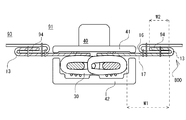
- FIG. 1 is a schematic top view of a slide fastener according to the present disclosure. It is a schematic diagram which shows the tape structure
- FIG. 6 is a schematic view showing another schematic tape structure of the upper surface or lower surface of the tape according to the present disclosure.
- FIG. 5 is a schematic view showing another schematic tape structure of the upper surface or lower surface of the tape according to the present disclosure.
- FIG. 10 is a schematic cross-sectional schematic view of a fastener stringer according to the present disclosure, schematically illustrating that the fastener tape is bent in the third tape region to form a folded portion.
- FIG. 1 is a schematic top view of a slide fastener according to the present disclosure. It is a schematic diagram which shows the tape structure
- FIG. 6 is a schematic
- FIG. 5 is a schematic view showing a fastener stringer according to the present disclosure sewn to a garment portion of a garment, with the attachment portion of the garment portion being sandwiched between the first and second tape areas; It is a schematic diagram which shows the state by which the slide fastener which concerns on this indication was sewn on with respect to the clothing part of clothing. It is a schematic diagram which shows the state which the fastener stringer which concerns on this indication was sewn on with respect to the clothing part of clothing, and unlike FIG.6 and FIG.7, the fastener tape and the clothing part are sewn together by two sutures. .
- FIG. 10 is a reference view showing that a bias tape is used for stitching a fastener tape and a garment portion.
- FIGS. 1 to 11 Each feature included in one or more embodiments and embodiments of the disclosure is not individually independent. Those skilled in the art can combine each embodiment and / or each feature without requiring an over description. Those skilled in the art can also understand the synergistic effects of this combination. Duplicate descriptions between the embodiments will be omitted in principle.
- the reference drawings are mainly for the description of the invention and may be simplified for the convenience of drawing.
- a plurality of features described with respect to a method of manufacturing a fastener tape and / or a garment will be understood as a combination of these features, as well as separate features independent of other features.
- An individual feature is understood as an independent individual feature without necessarily in combination with other features, but also as a combination with one or more other individual features. Describing all combinations of individual features is redundant as it is redundant to the person skilled in the art and is omitted.
- the individual features are specified by the expression "in some cases”. For example, the individual features are not only effective in the method of manufacturing the fastener tape and / or the garment disclosed in the drawings, but also universally applicable to the method of manufacturing various other fastener tapes and / or the garment. It is understood as a feature.
- the slide fastener 91 has a pair of left and right fastener stringers 92 and a slider 40 for opening and closing the pair of left and right fastener stringers 92.
- Each fastener stringer 92 has a fastener tape 10 and a fastener element 30 provided to the fastener tape 10.
- the forward movement of the slider 40 closes the pair of left and right fastener stringers 92, and the backward movement of the slider 40 opens the pair of left and right fastener stringers 92.
- the forward movement of the sliders 40 engages the fastener elements 30 of each fastener stringer 92, and the reverse movement of the sliders 40 disengages the fastener elements 30 of each fastener stringer 92.
- the back and forth direction is understood in light of the direction of movement of the slider.
- the left-right direction is understood in light of the direction in which the fastener stringers 92 are adjacent.
- the up and down direction is orthogonal to the front and back direction and the left and right direction.
- the slider 40 may be a metal or resin slider. In some cases, as shown in FIGS. 1 and 7, the slider 40 extends along the upper blade 41, the lower blade 42, and the vertical direction to connect the upper blade 41 and the lower blade 42 (not shown). A pair of left and right flanges 43 extending in the vertical direction (downward in the figure) from the left and right side edges of the upper wing plate 41, a pull attachment bracket 44, and a pull 45.
- the slider 40 has a pair of front ports on the left and right of the connecting column, and one rear port on the opposite side. When the slider 40 moves backward, each of the left and right fastener elements 30 disengaged by the connecting column moves from inside the slider to outside the slider via the front opening.
- each fastener stringer 92 is passed through a slit extending in the front-rear direction between the flange portion 43 of the slider 40 and the lower blade 42.
- slider 40 sliders of types other than the illustrated example may be employed.
- the fastener tape 10 is long in one direction.
- the longitudinal direction of the fastener tape 10 coincides with the front-rear direction.
- the fastener tape 10 has first and second side edges 1 and 2 extending along its longitudinal direction.
- the first and second side edge portions 1 and 2 can also be referred to as a pair of left and right side edges.
- a fastener element 30 is provided for the first side edge 1.
- a fastener element 30 is provided on the second side edge 2 in addition to the first side edge 1.
- the fastener tape 10 is a flexible fabric having a tape upper surface 16 (see FIG. 5) and a tape lower surface 17 opposite the tape upper surface 16 (see FIG. 5).
- the fastener element 30 is, in some cases, a coiled element in which monofilaments are spirally wound along the front-rear direction.
- the coiled element may be sewn to the first side edge 1 of the fastener tape 10 by means of a sewing thread.
- the fastener element 30 is not limited to a coiled element.
- a resin element or a metal element may be employed as the fastener element 30.
- the resin or metal elements may be arranged at a constant pitch in the longitudinal direction of the fastener tape 10.
- Each fastener stringer 92 comprises in some cases at least one of a front stop 51, a first reinforcement film 61, and a second reinforcement film 62.
- the front stop 51 is a resin or metal part, and is fixed to the first side edge 1 of the fastener tape 10 at the front end position of the fastener element 30.
- the front stop 51 prevents the slider 40 from moving forward, that is, defines the front stop position of the slider 40.
- the first reinforcing film 61 is a resin film for reinforcing the front end portion of the fastener tape 10.
- the second reinforcing film 62 is a resin film for reinforcing the rear end portion of the fastener tape 10.
- the respective films 61 and 62 are attached to the tape upper surface 16 and / or the tape lower surface 17 of the fastener tape 10. Each film 61, 62 may be attached to the fastener tape 10 by thermocompression bonding.
- the slide fastener 91 further comprises, in some cases, a snap fit fitting 52 so that the pair of fastener stringers 92 can be completely separated.
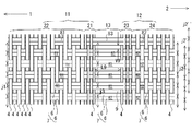
- Each fastener tape 10 includes at least a first tape area 11, a second tape area 12, and a third tape area 13 as described below.
- each fastener tape 10 can be divided into at least a first tape area 11, a second tape area 12, and a third tape area 13.
- each film 61, 62 is selectively affixed to the first tape area 11.
- each film 61, 62 is also affixed to the second tape area 12.
- a reinforcing film is not attached to the third tape area 13. It is avoided or suppressed that the bending of the fastener tape 10 in the third tape area 13 is prevented by the reinforcing film. It is also envisioned that a flexible reinforcing film may be applied to the third tape area 13.
- the lateral spacing W1 between the fastener element 30 and the third tape area 13 is greater than the lateral width W2 of the second tape area 12 (see FIGS. 5 and 9).
- the width W 2 of the second tape area 12 is smaller than the width W 1 between the fastener element 30 and the third tape area 13.
- the fastener tape 10 is composed of a plurality of warp yarns 4 extending in the longitudinal direction and at least one weft yarn 6 extending in the transverse direction orthogonal to the longitudinal direction.
- Each warp 4 straddles the weft 6 on the tape upper surface 16 side, and extends so as to repeatedly straddle the weft 6 on the tape lower surface 17 side.
- a portion of the warp 4 located above the weft 6 may be called a "floating portion”
- a portion of the warp 4 located below the weft 6 may be called a "sinking portion”.
- floats and sinks are alternately and continuously formed.
- the fastener tape 10 has a first tape area 11 in which a first portion 81 of the weft 6 straddled by the warp 4 is disposed at a first pitch interval j1, and a second portion 82 of the weft 6 straddles by the warp 4
- a second tape area 12 disposed at a second pitch interval j2 equal to one pitch interval j1 and a third tape area 13 located between the first tape area 11 and the second tape area 12 are provided.
- the first tape area 11 straddles the first portion 81 of the weft yarn 6 on the tape upper surface 16 side, and includes a plurality of warp yarns 4 extending repeatedly so as to straddle the first portion 81 of the weft yarn 6 on the tape lower surface 17 side.
- the second tape region 12 includes a plurality of warp yarns 4 extending repeatedly so as to straddle the second portion 82 of the weft 6 on the tape upper surface 16 side and straddle the second portion 82 of the weft 6 on the tape lower surface 17 side.
- the first portion 81 of the weft yarn 6 can be understood as the portion of the weft yarn 6 belonging to the first tape area 11.
- the second portion 82 of the weft yarn 6 can be understood as the portion of the weft yarn 6 belonging to the second tape area 12.
- the first tape area 11 is located closer to the first side edge 1 compared to the second side edge 2.
- the second tape area 12 is located closer to the second side edge 2 compared to the first side edge 1.
- the third tape area 13 is located closer to the second side edge 2 than the first side edge 1.
- the first side edge 1 is included in the first tape area 11 and / or the second side edge 2 is included in the second tape area 12.
- the first side edge 1 is included in the tape area of the tape tissue different from the first tape area 11 and / or the second side edge 2 is different from the second tape area 12 Included in the tape area of the tape tissue.
- the third tape region 13 there is no warp yarn 4, and a third portion 83 of the weft yarn 6 extending between the first and second portions 81, 82 of the weft yarn 6 is equal to the first or second pitch interval j1, j2.
- Three pitches j3 are provided.
- the third tape area 13 comprises only the third portion 83 of the third pitch interval j3.
- a horizontally long opening 9 is formed between the third tape section 83 adjacent in the longitudinal direction, extending between the first tape area 11 and the second tape area 12.
- the weft yarn 6 comprises a plurality of thinner yarns, or a plurality of thinner yarns are twisted.
- the third portion 83 of the weft thread 6 is not restrained by the warp threads 4, it can have a bulge in the longitudinal direction.
- the horizontally long opening 9 is totally or partially closed by the third portion 83 of the weft 6.
- the laterally long opening 9 is formed between the third portions 83.
- the longitudinal opening width V9 of the horizontal opening 9 may be constant over the distance between the first tape area 11 and the second tape area 12. This can be understood as a consequence of the third portion 83 of the weft 6 being arranged at the third pitch interval j3.
- the longitudinal opening width V9 of the opening 9 may vary due to the expansion of the third portion 83 of the weft 6. That is, fluctuation of the opening width V9 in the lateral direction according to the swelling of the third portion 83 is expected.
- the longitudinal opening width V9 of the opening 9 is a width corresponding to the space required for the warp yarn 4 to pass between the first or second portions 81, 82 of the adjacent weft yarns 6 in the longitudinal direction. In some cases, the longitudinal opening width V9 of the opening 9 is observed in a state in which the fastener tape 10 is horizontally drawn in the lateral direction and each third portion 83 extends in parallel in the lateral direction without swelling in the longitudinal direction.
- the lateral opening width L9 of the opening 9 is in some cases 0.3 mm or more. Additionally or alternatively, the lateral opening width L9 of the opening 9 is in some cases less than or equal to 2.6 mm. In some cases, including the illustrated example, the opening 9 is a horizontally long rectangular opening. Depending on the relative position of the second tape area 12 to the first tape area 11, the opening shape of the opening 9 may change. For example, when the second tape area 12 is shifted forward with respect to the first tape area 11, the third portion 83 obliquely extends, and the opening 9 has an obliquely extending opening shape.
- the third tape area 13 is an area in which the third portions 83 of the weft yarns 6 are arranged at the third pitch interval j 3, straddles the third portions 83 of the weft yarns 6 on the tape upper surface 16 side, and the weft yarns 6 on the tape lower surface 17 side. There is no warp 4 extending to repeat straddling the third portion 83 of the.
- the third tape area 13 comprises a plurality of water soluble warp yarns (not shown). The water-soluble warp extends across the third portion 83 of the weft 6 on the tape upper surface 16 side and repeatedly straddles the third portion 83 of the weft 6 on the tape lower surface 17 side.
- the third portion 83 of the weft yarn 6 can be understood as the portion of the weft yarn 6 belonging to the third tape area 13.
- the fastener tape 10 according to the present disclosure can be manufactured using an existing loom as it is.
- Each of the first to third portions 81, 82, 83 may be a longitudinally adjacent set of weft yarn portions 7 included in at least one weft yarn 6.
- the weft yarn portion 7 is a portion extending in the lateral direction.
- at least one weft yarn 6 is folded back at both ends in one fastener tape 10.
- wefts are woven with a set of portions of weft yarn 6 extending in the transversely opposite direction. This is because, when the loom weaves the fastener tape 10, the weft yarn 6 is drawn in the first lateral direction, and then the weft yarn 6 is drawn in the second direction opposite to the first lateral direction. possible.
- the first pitch interval j 1 is larger than the longitudinal width of the first portion 81 of the weft yarn 6 straddled by the warp yarn 4.
- the second pitch interval j 2 is larger than the longitudinal width of the second portion 82 of the weft yarn 6 straddled by the warp yarn 4.
- the third pitch interval j3 is larger than the longitudinal width of the third portion 83 of the weft 6.
- Each of the first to third pitch intervals j1, j2, j3 may be defined as an interval of the longitudinal center points of the pair of weft yarn portions 7. As illustrated in FIG. 2, the pitch spacing may be understood to be shifted in the longitudinal direction, such as pitch spacing j2 ', j2' '.
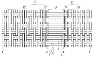
- the first tape area 11 is provided closer to the first side edge 1 than the first sub tape area 21 adjacent to the third tape area 13 and the first sub tape area 21.
- the tape organization of the first secondary tape area 21 and the tape organization of the second secondary tape area 22 are different.
- the warp 4 straddles one first portion 81 on the tape upper surface 16 side, and extends so as to repeat straddling one first portion 81 on the tape lower surface 17 side.
- the warp yarn 4 extends so as to straddle the two first portions 81 on the tape upper surface 16 side and repeatedly straddle the two first portions 81 on the tape lower surface 17 side.
- the portion of the warp 4 exposed to the tape upper surface 16 or the tape lower surface 17 is shifted in an oblique direction.
- the first secondary tape area 21 has 1/1 tape structure
- the second secondary tape area 22 has twill tape structure.
- one set of weft yarn portion 7 is one weft yarn.
- the warp yarns 4 and the weft yarns 6 are woven at a higher density than the second sub-tape region 22.
- the warp 4 in the first tape area 11 is prevented from moving to the third tape area 13 side without using an adhesive and / or without fixing the warp 4 and the weft 6. Be done.
- the tape organization of the first secondary tape area 21 and the tape organization of the second secondary tape area 22 are identical.
- the warp 4 straddles the two first portions 81 on the tape upper surface 16 side, and extends so as to repeatedly straddle the two first portions 81 on the tape lower surface 17 side.
- the warp 4 straddles the two first portions 81 on the tape upper surface 16 side, and extends so as to repeatedly straddle the two first portions 81 on the tape lower surface 17 side.
- the portion of the warp 4 exposed to the tape upper surface 16 or the tape lower surface 17 is shifted in an oblique direction.
- the first secondary tape area 21 and the second secondary tape area 22 have twill tape structure.
- the second tape area 12 includes a third secondary tape area 23 adjacent to the third tape area 13 and a fourth secondary tape area 24 provided closer to the second side edge 2 than the third secondary tape area 23.
- the second tape area 12 may have a 1/1 tape organization.
- the tape organization of the third secondary tape area 23 and the tape organization of the fourth secondary tape area 24 are identical or different.
- the tape system of the third minor tape area 23 and the tape system of the fourth minor tape area 24 are identical and have 1/1 tape system.
- the warp yarns 4 are woven in at a higher density as compared with the fourth secondary tape area 24.
- the third and fourth secondary tape areas 23, 24 have a 1/1 tape structure. In some cases, including FIG.
- the tape organization of the third secondary tape area 23 and the tape organization of the fourth secondary tape area 24 are different.
- the same description as described for the first sub tape area 21 and the second sub tape area 22 of the first tape area 11 applies to the third sub tape area 23 and the fourth sub tape area 24 of the second sub tape area 22.
- the warp yarn 4 included in the first sub-tape region 21 is thinner than the warp yarn 4 included in the second sub-tape region 22. Additionally or alternatively, the warp yarns 4 contained in the third sub-tape region 23 are thinner than the warp yarns 4 contained in the fourth sub-tape region 24. Thus, the warp 4 in the first tape area 11 is prevented from moving to the third tape area 13 side without using an adhesive and / or without fixing the warp 4 and the weft 6. Be done.
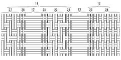
- FIG. 4 shows an example in which two or more of the third tape areas described above are provided.
- the fastener tape 10 additionally includes, in addition to the third tape area 13, at least one duplicate third tape area 13 ′ of the same tape structure.
- the third portion 83 of the weft yarn 6 extending between the first and second portions 81 and 82 of the weft yarn 6 does not have the warp yarn 4, and the first or second pitch interval j1,1. It can be understood as any area arranged at a third pitch spacing j3 equal to j2.
- the replicated third tape area 13 'illustrated in FIG. 4 may differ in lateral width from the third tape area 13 illustrated in FIG.
- a fifth sub-tape area 25 of the same tape structure as the first sub-tape area 21 is disposed between the replicated third tape area 13 ′ and the second sub-tape area 22.
- a sixth secondary tape area 26 is provided adjacent to the duplicate third tape area 13 ′ on the first side edge 1 side, and has the same tape structure as the first secondary tape area 21.
- a seventh secondary tape area 27 is provided adjacent to the sixth secondary tape area 26 on the first side edge 1 side, and has a twill tape structure.
- the tape structure of the secondary tape area included in the first tape area 11 or the second tape area 12 is not limited to the combination shown and described, and various combinations are possible. In some cases, the entire first tape area 11 is twill weave tape tissue and / or the entire second tape area 12 is twill weave tape tissue.
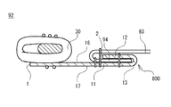
- the fastener tape 10 can be bent at the third tape area 13 to arrange the second tape area 12 on the first tape area 11.
- the fastener tape 10 has a folded portion 800 bent and folded back at the third tape area 13, and the second tape area 12 is disposed on the first tape area 11.
- An attachment portion 94 of the garment portion 93 may be disposed between the first tape area 11 and the second tape area 12 as shown in FIG. Because of the improved flexibility of the fastener tape 10 based on the third tape region 13, the attachment portion 94 of the garment portion 93 may be between the first tape region 11 and the second tape region 12 of the fastener tape 10 as shown in FIG.
- the workability of sandwiching is improved, and alternatively or additionally, the workability of stitching the fastener tape 10 and the garment portion 93 is also improved.
- the fastener tape 10 covers the attachment portion 94 of the garment portion 93 without using the bias tape 900, and the exposure of the attachment portion 94 of the garment portion 93 is avoided or suppressed without relying on the bias tape 900.
- the omission of the bias tape 900 reduces the weight of the clothes.
- the third portions 83 extending in the lateral direction are arranged at a constant pitch interval j 3 in the longitudinal direction, which gives directionality to bending of the fastener tape 10.
- FIG. 7 discloses a garment including the slide fastener 91 described above and a garment portion 93 to which the slide fastener 91 is sewn.
- the garment portion 93 and the fastener tape 10 are sewn together with the attachment portion 94 of the garment portion 93 being sandwiched between the first tape area 11 and the second tape area 12 of the fastener tape 10.
- the garment may include any type and size coat or trousers.
- FIG. 8 shows that the garment portion 93 and the fastener tape 10 are sewn together by two longitudinally extending sutures. As compared with the case of using three threads as in the case of FIGS. 6 and 7, the shortening of the sewing process time or the weight reduction of the clothes is promoted.
- FIG. 9 shows that the fastener element 30 is disposed on the lower surface 17 of the tape and that a slider 40 suitable for this is used. In this manner, fastener element 30 may be secured at various locations on fastener tape 10. In some cases, fastener elements 30 are secured to the second tape area 12 to produce fastener stringers for concealed slide fasteners. A resin film or the like may be used to maintain the third tape area 13 in an arc-shaped curved state.
- FIG. 10 shows a method of manufacturing a garment according to the present disclosure.
- the method of manufacturing the garment includes a step of forming the folded portion 800 on the fastener tape 10 and a sewing step for stitching the fastener tape 10 and the garment. These steps may be performed at different or the same time.
- the step of forming the folded portion 800 on the fastener tape 10 may be a step of bending the fastener tape 10 in the third tape area 13 of the fastener tape 10 to form the folded portion 800 on the fastener tape 10.
- the attachment portion 94 of the garment portion 93 included in the garment is pinched between the first tape area 11 and the second tape area 12 of the fastener tape 10 in this step.
- the garment portion 93 and the fastener tape 10 are sewn together in a state in which the attachment portion 94 of the garment portion 93 included in the garment is sandwiched between the first tape area 11 and the second tape area 12 of the fastener tape 10. It is possible.
- the adoption of the fastener tape 10 according to the present disclosure enables the garment portion 93 and the fastener tape 10 to be sewn together without the bias tape 900.
Landscapes
- Slide Fasteners (AREA)
Abstract
L'invention concerne une bande de fixation (10) qui comprend une pluralité de fils de chaîne (4) et un ou plusieurs fils de trame (6). Chacun des fils de chaîne (4) s'étend de manière à croiser de manière répétée un fil de trame (6) sur le côté de la surface supérieure de la bande (16), puis croiser un fil de trame (6) sur le côté de la surface inférieure de la bande (17). Dans une première région de bande (11), des premières portions (81) des fils de trame (6) que croisent les fils de chaîne (4) sont disposées à une première distance de pas (j1). Dans une deuxième région de bande (12), des deuxièmes portions (82) des fils de trame (6) que croisent les fils de chaîne (4) sont disposées à une deuxième distance de pas (j2) qui est égale à la première distance de pas (j1). Dans une troisième région de bande (13), située entre la première région de bande (11) et la deuxième région de bande (12), des troisièmes portions (83) des fils de trame (6), dans lesquelles des fils de chaîne (4) sont absents et qui s'étendent entre les première et deuxième portions (81, 82) du fil de trame (6), sont disposées à une troisième distance de pas (j3) qui est égale à la première ou à la deuxième distance de pas (j1, j2).
Priority Applications (5)
| Application Number | Priority Date | Filing Date | Title |
|---|---|---|---|
| PCT/JP2017/043168 WO2019106806A1 (fr) | 2017-11-30 | 2017-11-30 | Bande de fixation, demi-chaîne de fermeture, fermeture à glissière, vêtement et procédé de fabrication de vêtement |
| PCT/JP2018/008873 WO2019106857A1 (fr) | 2017-11-30 | 2018-03-07 | Fermeture à glissière reliée à un matériau souple, procédé associé, et bande de fixation |
| US16/765,956 US11406164B2 (en) | 2017-11-30 | 2018-03-07 | Slide fastener joined to flexible material |
| CN201880077339.8A CN111491534B (zh) | 2017-11-30 | 2018-03-07 | 与挠性件结合起来的拉链、与该拉链有关的方法、以及拉链带 |
| TW107126672A TWI704877B (zh) | 2017-11-30 | 2018-08-01 | 結合於可撓性材的拉鏈、關於此的方法、結合有拉鏈的可撓性材的製造方法、拉鏈鏈布、拉鏈鏈帶、拉鏈、衣類及衣類的製造方法 |
Applications Claiming Priority (1)
| Application Number | Priority Date | Filing Date | Title |
|---|---|---|---|
| PCT/JP2017/043168 WO2019106806A1 (fr) | 2017-11-30 | 2017-11-30 | Bande de fixation, demi-chaîne de fermeture, fermeture à glissière, vêtement et procédé de fabrication de vêtement |
Publications (1)
| Publication Number | Publication Date |
|---|---|
| WO2019106806A1 true WO2019106806A1 (fr) | 2019-06-06 |
Family
ID=66664810
Family Applications (2)
| Application Number | Title | Priority Date | Filing Date |
|---|---|---|---|
| PCT/JP2017/043168 WO2019106806A1 (fr) | 2017-11-30 | 2017-11-30 | Bande de fixation, demi-chaîne de fermeture, fermeture à glissière, vêtement et procédé de fabrication de vêtement |
| PCT/JP2018/008873 WO2019106857A1 (fr) | 2017-11-30 | 2018-03-07 | Fermeture à glissière reliée à un matériau souple, procédé associé, et bande de fixation |
Family Applications After (1)
| Application Number | Title | Priority Date | Filing Date |
|---|---|---|---|
| PCT/JP2018/008873 WO2019106857A1 (fr) | 2017-11-30 | 2018-03-07 | Fermeture à glissière reliée à un matériau souple, procédé associé, et bande de fixation |
Country Status (4)
| Country | Link |
|---|---|
| US (1) | US11406164B2 (fr) |
| CN (1) | CN111491534B (fr) |
| TW (1) | TWI704877B (fr) |
| WO (2) | WO2019106806A1 (fr) |
Cited By (1)
| Publication number | Priority date | Publication date | Assignee | Title |
|---|---|---|---|---|
| WO2023188040A1 (fr) * | 2022-03-29 | 2023-10-05 | Ykk株式会社 | Demi-chaîne de fermeture à glissière pourvue de rangées d'éléments métalliques, fermeture à glissière pourvue de celle-ci, et article pourvu d'une fermeture à glissière |
Families Citing this family (3)
| Publication number | Priority date | Publication date | Assignee | Title |
|---|---|---|---|---|
| CN207118675U (zh) * | 2017-07-12 | 2018-03-20 | 吉田拉链(深圳)有限公司 | 拉链带、拉链及拉链带制作设备 |
| CN113768254B (zh) * | 2021-09-27 | 2023-04-14 | 福建浔兴拉链科技股份有限公司 | 拉链带、拉链、应用拉链的物品及拉链带织造方法 |
| WO2023242963A1 (fr) * | 2022-06-14 | 2023-12-21 | Ykk株式会社 | Demi-chaîne étanche à l'eau et élément de fixation étanche à l'eau |
Citations (2)
| Publication number | Priority date | Publication date | Assignee | Title |
|---|---|---|---|---|
| JPS59179606U (ja) * | 1983-05-20 | 1984-11-30 | 滝清株式会社 | フアスナ− |
| JP3208550U (ja) * | 2016-11-07 | 2017-01-26 | Ykk株式会社 | スライドファスナー用ファスナーテープ及びスライドファスナー |
Family Cites Families (18)
| Publication number | Priority date | Publication date | Assignee | Title |
|---|---|---|---|---|
| US1933290A (en) * | 1929-05-13 | 1933-10-31 | Winterhalter Martin | Ripping closure and the like |
| NL135619C (fr) * | 1966-01-31 | |||
| DE1610367B1 (de) * | 1966-03-03 | 1970-01-29 | Opti Werk Gmbh & Co | Reissverschluss und Verfahren zu seiner Herstellung |
| JPS51135709U (fr) | 1975-04-22 | 1976-11-02 | ||
| JPS5836811U (ja) | 1981-09-05 | 1983-03-10 | ワイケイケイ株式会社 | 広巾テ−プを有するスライドファスナ− |
| JPS59108502A (ja) * | 1982-12-14 | 1984-06-23 | ワイケイケイ株式会社 | 防水性を有するスライドファスナ− |
| JPH0410711U (fr) * | 1990-05-18 | 1992-01-29 | ||
| JP3763743B2 (ja) * | 2001-01-31 | 2006-04-05 | Ykk株式会社 | スライドファスナーの製造方法 |
| AU2004100214B4 (en) * | 2003-06-27 | 2005-02-03 | Landor & Hawa International Limited | Suitcase |
| JP4312676B2 (ja) * | 2004-07-26 | 2009-08-12 | Ykk株式会社 | スライドファスナー用ストリンガー |
| JP3152100U (ja) | 2009-05-07 | 2009-07-16 | Ykk株式会社 | 被覆帯付きスライドファスナー |
| JP5328519B2 (ja) * | 2009-06-26 | 2013-10-30 | 株式会社シマノ | スライドファスナの取付構造 |
| GB0912179D0 (en) * | 2009-07-13 | 2009-08-26 | Ykk Europ Ltd | Watertight zip fastener |
| TW201127314A (en) * | 2010-02-12 | 2011-08-16 | xi-wu Jiang | Zipper for luggage |
| WO2012120602A1 (fr) * | 2011-03-04 | 2012-09-13 | Ykk株式会社 | Fermeture à glissière et procédé de fabrication de cette dernière |
| WO2014010078A1 (fr) * | 2012-07-13 | 2014-01-16 | Ykk株式会社 | Demi-chaîne de fermeture et fermeture à glissière |
| TWM462020U (zh) * | 2013-02-08 | 2013-09-21 | Tang ting ting | 具保護罩之行李箱結構 |
| JP6980557B2 (ja) * | 2018-02-19 | 2021-12-15 | Ykk株式会社 | ファスナーストリンガー、スライドファスナーおよびファスナーストリンガー取付構造 |
-
2017
- 2017-11-30 WO PCT/JP2017/043168 patent/WO2019106806A1/fr active Application Filing
-
2018
- 2018-03-07 CN CN201880077339.8A patent/CN111491534B/zh active Active
- 2018-03-07 WO PCT/JP2018/008873 patent/WO2019106857A1/fr active Application Filing
- 2018-03-07 US US16/765,956 patent/US11406164B2/en active Active
- 2018-08-01 TW TW107126672A patent/TWI704877B/zh active
Patent Citations (2)
| Publication number | Priority date | Publication date | Assignee | Title |
|---|---|---|---|---|
| JPS59179606U (ja) * | 1983-05-20 | 1984-11-30 | 滝清株式会社 | フアスナ− |
| JP3208550U (ja) * | 2016-11-07 | 2017-01-26 | Ykk株式会社 | スライドファスナー用ファスナーテープ及びスライドファスナー |
Cited By (1)
| Publication number | Priority date | Publication date | Assignee | Title |
|---|---|---|---|---|
| WO2023188040A1 (fr) * | 2022-03-29 | 2023-10-05 | Ykk株式会社 | Demi-chaîne de fermeture à glissière pourvue de rangées d'éléments métalliques, fermeture à glissière pourvue de celle-ci, et article pourvu d'une fermeture à glissière |
Also Published As
| Publication number | Publication date |
|---|---|
| CN111491534A (zh) | 2020-08-04 |
| TW201924566A (zh) | 2019-07-01 |
| WO2019106857A1 (fr) | 2019-06-06 |
| US11406164B2 (en) | 2022-08-09 |
| TWI704877B (zh) | 2020-09-21 |
| US20200359753A1 (en) | 2020-11-19 |
| CN111491534B (zh) | 2023-06-16 |
Similar Documents
| Publication | Publication Date | Title |
|---|---|---|
| WO2019106806A1 (fr) | Bande de fixation, demi-chaîne de fermeture, fermeture à glissière, vêtement et procédé de fabrication de vêtement | |
| JP5667200B2 (ja) | スライドファスナー用の織物製テープ | |
| US9668549B2 (en) | Fastener tape for slide fastener, and slide fastener | |
| JP4762113B2 (ja) | 隠しスライドファスナー用ファスナーストリンガー | |
| TWI448259B (zh) | Zipper and its manufacturing method | |
| JP4312200B2 (ja) | 編織込み隠しスライドファスナー | |
| WO2014010078A1 (fr) | Demi-chaîne de fermeture et fermeture à glissière | |
| WO2012070116A1 (fr) | Demi-chaîne de fermeture et fermeture à glissière | |
| JP5795074B2 (ja) | スライドファスナー及び隠しスライドファスナー | |
| WO2014002218A1 (fr) | Renfort de fermeture et fermeture à glissière | |
| TWI634853B (zh) | Zipper chain cloth and zipper chain cloth manufacturing method | |
| JP3208550U (ja) | スライドファスナー用ファスナーテープ及びスライドファスナー | |
| JP7191499B2 (ja) | ファスナーチェーン、及びファスナーチェーンの製造方法 | |
| US10531713B2 (en) | Fastener stringer and slide fastener | |
| JP6794083B2 (ja) | ファスナーストリンガー | |
| TWM530063U (zh) | 拉鏈 | |
| JP3045440B2 (ja) | 織込みスライドファスナー | |
| JP2002085113A (ja) | 織込みスライドファスナーストリンガー |
Legal Events
| Date | Code | Title | Description |
|---|---|---|---|
| 121 | Ep: the epo has been informed by wipo that ep was designated in this application |
Ref document number: 17933743 Country of ref document: EP Kind code of ref document: A1 |
|
| NENP | Non-entry into the national phase |
Ref country code: DE |
|
| 122 | Ep: pct application non-entry in european phase |
Ref document number: 17933743 Country of ref document: EP Kind code of ref document: A1 |
|
| NENP | Non-entry into the national phase |
Ref country code: JP |