WO2019106806A1 - Fastener tape, fastener stringer, slide fastener, garment and manufacturing process for garment - Google Patents
Fastener tape, fastener stringer, slide fastener, garment and manufacturing process for garment Download PDFInfo
- Publication number
- WO2019106806A1 WO2019106806A1 PCT/JP2017/043168 JP2017043168W WO2019106806A1 WO 2019106806 A1 WO2019106806 A1 WO 2019106806A1 JP 2017043168 W JP2017043168 W JP 2017043168W WO 2019106806 A1 WO2019106806 A1 WO 2019106806A1
- Authority
- WO
- WIPO (PCT)
- Prior art keywords
- tape
- fastener
- area
- garment
- weft
- Prior art date
Links
Images


Classifications
-
- A—HUMAN NECESSITIES
- A44—HABERDASHERY; JEWELLERY
- A44B—BUTTONS, PINS, BUCKLES, SLIDE FASTENERS, OR THE LIKE
- A44B19/00—Slide fasteners
- A44B19/24—Details
- A44B19/26—Sliders
-
- A—HUMAN NECESSITIES
- A44—HABERDASHERY; JEWELLERY
- A44B—BUTTONS, PINS, BUCKLES, SLIDE FASTENERS, OR THE LIKE
- A44B19/00—Slide fasteners
- A44B19/24—Details
- A44B19/34—Stringer tapes; Flaps secured to stringers for covering the interlocking members
-
- A—HUMAN NECESSITIES
- A44—HABERDASHERY; JEWELLERY
- A44B—BUTTONS, PINS, BUCKLES, SLIDE FASTENERS, OR THE LIKE
- A44B19/00—Slide fasteners
- A44B19/10—Slide fasteners with a one-piece interlocking member on each stringer tape
- A44B19/12—Interlocking member in the shape of a continuous helix
-
- A—HUMAN NECESSITIES
- A44—HABERDASHERY; JEWELLERY
- A44B—BUTTONS, PINS, BUCKLES, SLIDE FASTENERS, OR THE LIKE
- A44B19/00—Slide fasteners
- A44B19/24—Details
- A44B19/34—Stringer tapes; Flaps secured to stringers for covering the interlocking members
- A44B19/346—Woven stringer tapes
Definitions
- the present disclosure relates to fastener tapes, fastener stringers, slide fasteners, garments and methods of making garments.
- Patent Document 1 discloses a slide fastener in which the tape of one stringer can be positioned on the tape surface of the other stringer beyond the meshing tooth portion.
- page 4 lines 3-5 of the same document, it is described that the warp density of the folded portion is rougher than other portions to facilitate folding.
- Patent Document 2 discloses a tape for a slide fastener suitable for handicrafts.
- holes defined by zigzag wefts are used as through holes for handicraft yarn (see also FIG. 2 of the same document). ).
- the inventors of the present invention have newly found the meaning of providing a fastener tape having directionality with respect to the bending of the fastener tape.
- the fastener tape according to an aspect of the present disclosure comprises a plurality of warps extending in the longitudinal direction and at least one weft extending in the transverse direction orthogonal to the longitudinal direction, and each warp is the weft on the upper surface side of the tape.
- a fastener tape extending so as to repeat straddling the weft on the lower surface side of the tape, A first tape region in which a first portion of the weft yarn straddled by the warp yarn is disposed at a first pitch interval; A second tape region in which a second portion of the weft yarn straddled by the warp yarn is disposed at a second pitch interval equal to the first pitch interval; A third tape area located between the first tape area and the second tape area; In the third tape area, the warp does not exist, and a third portion of the weft extending between the first and second portions of the weft is disposed at a third pitch interval equal to the first or second pitch interval. Be done.
- each of the first to third portions is the longitudinally adjacent set of weft portions included in the at least one weft.
- a laterally long opening is formed between the first tape area and the second tape area between the longitudinally adjacent third portions.
- the longitudinal opening width of the opening is a width corresponding to the space required for the warp to pass between the first or second portion of the adjacent weft in the longitudinal direction.
- a laterally long opening is formed between the first tape area and the second tape area between the longitudinally adjacent third portions.
- the lateral aperture width of the aperture is greater than twice the longitudinal aperture width of the aperture.
- first and second side edges extending along the longitudinal direction
- the first tape area is located closer to the first side edge as compared to the second side edge
- the second tape area is positioned closer to the second side edge as compared to the first side edge.
- the first tape area may be a first secondary tape area adjacent to the third tape area, and a second secondary tape disposed closer to the first side edge than the first secondary tape area Including the region, The tape organization of the first secondary tape area and the tape organization of the second secondary tape area are different.
- the warp and weft yarns are woven at a higher density in the first secondary tape region as compared to the second secondary tape region.
- the first secondary tape area has 1/1 tape organization.
- the warp included in the first secondary tape area is thinner than the warp included in the second secondary tape area.
- the second tape area has 1/1 tape organization.
- the second tape area is a third sub-tape area adjacent to the third tape area and a fourth sub-tape disposed closer to the second side edge than the third sub-tape area Including the region, The tape organization of the third secondary tape area and the tape organization of the fourth secondary tape area are different.
- the warp and the weft are woven at a higher density in the third secondary tape region as compared to the fourth secondary tape region.
- the third secondary tape area has 1/1 tape organization.
- the warp included in the third secondary tape area is thinner than the warp included in the fourth secondary tape area.
- a fastener stringer according to one aspect of the present disclosure is any one of the above fastener tapes, A fastener element is provided for the first side edge of the fastener tape.
- the third tape area is disposed closer to the second side edge than the first side edge.
- a slide fastener includes a pair of fastener stringers, each of which is the above-described fastener stringer.
- a slider is provided to open and close the pair of fastener stringers.
- the lateral spacing between the fastener element and the third tape area is greater than the lateral width of the second tape area.
- a garment according to the present disclosure comprises the above-mentioned slide fastener, A garment comprising a garment portion to which the slide fastener is sewn.
- the garment portion and the fastener tape are sewn together with the attachment portion of the garment portion sandwiched between the first tape area and the second tape area of the fastener tape.
- the garment portion and the fastener tape are sewn together by the at least two longitudinally extending sutures.
- a method of producing a garment according to the present disclosure is a method of producing a garment to which the above-mentioned slide fastener is sewn. Bending the fastener tape in the third tape area of the fastener tape to form a folded portion; And stitching the garment portion and the fastener tape in a state where the attachment portion of the garment portion included in the garment is sandwiched between the first tape area and the second tape area of the fastener tape.
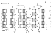
- FIG. 1 is a schematic top view of a slide fastener according to the present disclosure. It is a schematic diagram which shows the tape structure
- FIG. 6 is a schematic view showing another schematic tape structure of the upper surface or lower surface of the tape according to the present disclosure.
- FIG. 5 is a schematic view showing another schematic tape structure of the upper surface or lower surface of the tape according to the present disclosure.
- FIG. 10 is a schematic cross-sectional schematic view of a fastener stringer according to the present disclosure, schematically illustrating that the fastener tape is bent in the third tape region to form a folded portion.
- FIG. 1 is a schematic top view of a slide fastener according to the present disclosure. It is a schematic diagram which shows the tape structure
- FIG. 6 is a schematic
- FIG. 5 is a schematic view showing a fastener stringer according to the present disclosure sewn to a garment portion of a garment, with the attachment portion of the garment portion being sandwiched between the first and second tape areas; It is a schematic diagram which shows the state by which the slide fastener which concerns on this indication was sewn on with respect to the clothing part of clothing. It is a schematic diagram which shows the state which the fastener stringer which concerns on this indication was sewn on with respect to the clothing part of clothing, and unlike FIG.6 and FIG.7, the fastener tape and the clothing part are sewn together by two sutures. .
- FIG. 10 is a reference view showing that a bias tape is used for stitching a fastener tape and a garment portion.
- FIGS. 1 to 11 Each feature included in one or more embodiments and embodiments of the disclosure is not individually independent. Those skilled in the art can combine each embodiment and / or each feature without requiring an over description. Those skilled in the art can also understand the synergistic effects of this combination. Duplicate descriptions between the embodiments will be omitted in principle.
- the reference drawings are mainly for the description of the invention and may be simplified for the convenience of drawing.
- a plurality of features described with respect to a method of manufacturing a fastener tape and / or a garment will be understood as a combination of these features, as well as separate features independent of other features.
- An individual feature is understood as an independent individual feature without necessarily in combination with other features, but also as a combination with one or more other individual features. Describing all combinations of individual features is redundant as it is redundant to the person skilled in the art and is omitted.
- the individual features are specified by the expression "in some cases”. For example, the individual features are not only effective in the method of manufacturing the fastener tape and / or the garment disclosed in the drawings, but also universally applicable to the method of manufacturing various other fastener tapes and / or the garment. It is understood as a feature.
- the slide fastener 91 has a pair of left and right fastener stringers 92 and a slider 40 for opening and closing the pair of left and right fastener stringers 92.
- Each fastener stringer 92 has a fastener tape 10 and a fastener element 30 provided to the fastener tape 10.
- the forward movement of the slider 40 closes the pair of left and right fastener stringers 92, and the backward movement of the slider 40 opens the pair of left and right fastener stringers 92.
- the forward movement of the sliders 40 engages the fastener elements 30 of each fastener stringer 92, and the reverse movement of the sliders 40 disengages the fastener elements 30 of each fastener stringer 92.
- the back and forth direction is understood in light of the direction of movement of the slider.
- the left-right direction is understood in light of the direction in which the fastener stringers 92 are adjacent.
- the up and down direction is orthogonal to the front and back direction and the left and right direction.
- the slider 40 may be a metal or resin slider. In some cases, as shown in FIGS. 1 and 7, the slider 40 extends along the upper blade 41, the lower blade 42, and the vertical direction to connect the upper blade 41 and the lower blade 42 (not shown). A pair of left and right flanges 43 extending in the vertical direction (downward in the figure) from the left and right side edges of the upper wing plate 41, a pull attachment bracket 44, and a pull 45.
- the slider 40 has a pair of front ports on the left and right of the connecting column, and one rear port on the opposite side. When the slider 40 moves backward, each of the left and right fastener elements 30 disengaged by the connecting column moves from inside the slider to outside the slider via the front opening.
- each fastener stringer 92 is passed through a slit extending in the front-rear direction between the flange portion 43 of the slider 40 and the lower blade 42.
- slider 40 sliders of types other than the illustrated example may be employed.
- the fastener tape 10 is long in one direction.
- the longitudinal direction of the fastener tape 10 coincides with the front-rear direction.
- the fastener tape 10 has first and second side edges 1 and 2 extending along its longitudinal direction.
- the first and second side edge portions 1 and 2 can also be referred to as a pair of left and right side edges.
- a fastener element 30 is provided for the first side edge 1.
- a fastener element 30 is provided on the second side edge 2 in addition to the first side edge 1.
- the fastener tape 10 is a flexible fabric having a tape upper surface 16 (see FIG. 5) and a tape lower surface 17 opposite the tape upper surface 16 (see FIG. 5).
- the fastener element 30 is, in some cases, a coiled element in which monofilaments are spirally wound along the front-rear direction.
- the coiled element may be sewn to the first side edge 1 of the fastener tape 10 by means of a sewing thread.
- the fastener element 30 is not limited to a coiled element.
- a resin element or a metal element may be employed as the fastener element 30.
- the resin or metal elements may be arranged at a constant pitch in the longitudinal direction of the fastener tape 10.
- Each fastener stringer 92 comprises in some cases at least one of a front stop 51, a first reinforcement film 61, and a second reinforcement film 62.
- the front stop 51 is a resin or metal part, and is fixed to the first side edge 1 of the fastener tape 10 at the front end position of the fastener element 30.
- the front stop 51 prevents the slider 40 from moving forward, that is, defines the front stop position of the slider 40.
- the first reinforcing film 61 is a resin film for reinforcing the front end portion of the fastener tape 10.
- the second reinforcing film 62 is a resin film for reinforcing the rear end portion of the fastener tape 10.
- the respective films 61 and 62 are attached to the tape upper surface 16 and / or the tape lower surface 17 of the fastener tape 10. Each film 61, 62 may be attached to the fastener tape 10 by thermocompression bonding.
- the slide fastener 91 further comprises, in some cases, a snap fit fitting 52 so that the pair of fastener stringers 92 can be completely separated.
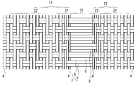
- Each fastener tape 10 includes at least a first tape area 11, a second tape area 12, and a third tape area 13 as described below.
- each fastener tape 10 can be divided into at least a first tape area 11, a second tape area 12, and a third tape area 13.
- each film 61, 62 is selectively affixed to the first tape area 11.
- each film 61, 62 is also affixed to the second tape area 12.
- a reinforcing film is not attached to the third tape area 13. It is avoided or suppressed that the bending of the fastener tape 10 in the third tape area 13 is prevented by the reinforcing film. It is also envisioned that a flexible reinforcing film may be applied to the third tape area 13.
- the lateral spacing W1 between the fastener element 30 and the third tape area 13 is greater than the lateral width W2 of the second tape area 12 (see FIGS. 5 and 9).
- the width W 2 of the second tape area 12 is smaller than the width W 1 between the fastener element 30 and the third tape area 13.
- the fastener tape 10 is composed of a plurality of warp yarns 4 extending in the longitudinal direction and at least one weft yarn 6 extending in the transverse direction orthogonal to the longitudinal direction.
- Each warp 4 straddles the weft 6 on the tape upper surface 16 side, and extends so as to repeatedly straddle the weft 6 on the tape lower surface 17 side.
- a portion of the warp 4 located above the weft 6 may be called a "floating portion”
- a portion of the warp 4 located below the weft 6 may be called a "sinking portion”.
- floats and sinks are alternately and continuously formed.
- the fastener tape 10 has a first tape area 11 in which a first portion 81 of the weft 6 straddled by the warp 4 is disposed at a first pitch interval j1, and a second portion 82 of the weft 6 straddles by the warp 4
- a second tape area 12 disposed at a second pitch interval j2 equal to one pitch interval j1 and a third tape area 13 located between the first tape area 11 and the second tape area 12 are provided.
- the first tape area 11 straddles the first portion 81 of the weft yarn 6 on the tape upper surface 16 side, and includes a plurality of warp yarns 4 extending repeatedly so as to straddle the first portion 81 of the weft yarn 6 on the tape lower surface 17 side.
- the second tape region 12 includes a plurality of warp yarns 4 extending repeatedly so as to straddle the second portion 82 of the weft 6 on the tape upper surface 16 side and straddle the second portion 82 of the weft 6 on the tape lower surface 17 side.
- the first portion 81 of the weft yarn 6 can be understood as the portion of the weft yarn 6 belonging to the first tape area 11.
- the second portion 82 of the weft yarn 6 can be understood as the portion of the weft yarn 6 belonging to the second tape area 12.
- the first tape area 11 is located closer to the first side edge 1 compared to the second side edge 2.
- the second tape area 12 is located closer to the second side edge 2 compared to the first side edge 1.
- the third tape area 13 is located closer to the second side edge 2 than the first side edge 1.
- the first side edge 1 is included in the first tape area 11 and / or the second side edge 2 is included in the second tape area 12.
- the first side edge 1 is included in the tape area of the tape tissue different from the first tape area 11 and / or the second side edge 2 is different from the second tape area 12 Included in the tape area of the tape tissue.
- the third tape region 13 there is no warp yarn 4, and a third portion 83 of the weft yarn 6 extending between the first and second portions 81, 82 of the weft yarn 6 is equal to the first or second pitch interval j1, j2.
- Three pitches j3 are provided.
- the third tape area 13 comprises only the third portion 83 of the third pitch interval j3.
- a horizontally long opening 9 is formed between the third tape section 83 adjacent in the longitudinal direction, extending between the first tape area 11 and the second tape area 12.
- the weft yarn 6 comprises a plurality of thinner yarns, or a plurality of thinner yarns are twisted.
- the third portion 83 of the weft thread 6 is not restrained by the warp threads 4, it can have a bulge in the longitudinal direction.
- the horizontally long opening 9 is totally or partially closed by the third portion 83 of the weft 6.
- the laterally long opening 9 is formed between the third portions 83.
- the longitudinal opening width V9 of the horizontal opening 9 may be constant over the distance between the first tape area 11 and the second tape area 12. This can be understood as a consequence of the third portion 83 of the weft 6 being arranged at the third pitch interval j3.
- the longitudinal opening width V9 of the opening 9 may vary due to the expansion of the third portion 83 of the weft 6. That is, fluctuation of the opening width V9 in the lateral direction according to the swelling of the third portion 83 is expected.
- the longitudinal opening width V9 of the opening 9 is a width corresponding to the space required for the warp yarn 4 to pass between the first or second portions 81, 82 of the adjacent weft yarns 6 in the longitudinal direction. In some cases, the longitudinal opening width V9 of the opening 9 is observed in a state in which the fastener tape 10 is horizontally drawn in the lateral direction and each third portion 83 extends in parallel in the lateral direction without swelling in the longitudinal direction.
- the lateral opening width L9 of the opening 9 is in some cases 0.3 mm or more. Additionally or alternatively, the lateral opening width L9 of the opening 9 is in some cases less than or equal to 2.6 mm. In some cases, including the illustrated example, the opening 9 is a horizontally long rectangular opening. Depending on the relative position of the second tape area 12 to the first tape area 11, the opening shape of the opening 9 may change. For example, when the second tape area 12 is shifted forward with respect to the first tape area 11, the third portion 83 obliquely extends, and the opening 9 has an obliquely extending opening shape.
- the third tape area 13 is an area in which the third portions 83 of the weft yarns 6 are arranged at the third pitch interval j 3, straddles the third portions 83 of the weft yarns 6 on the tape upper surface 16 side, and the weft yarns 6 on the tape lower surface 17 side. There is no warp 4 extending to repeat straddling the third portion 83 of the.
- the third tape area 13 comprises a plurality of water soluble warp yarns (not shown). The water-soluble warp extends across the third portion 83 of the weft 6 on the tape upper surface 16 side and repeatedly straddles the third portion 83 of the weft 6 on the tape lower surface 17 side.
- the third portion 83 of the weft yarn 6 can be understood as the portion of the weft yarn 6 belonging to the third tape area 13.
- the fastener tape 10 according to the present disclosure can be manufactured using an existing loom as it is.
- Each of the first to third portions 81, 82, 83 may be a longitudinally adjacent set of weft yarn portions 7 included in at least one weft yarn 6.
- the weft yarn portion 7 is a portion extending in the lateral direction.
- at least one weft yarn 6 is folded back at both ends in one fastener tape 10.
- wefts are woven with a set of portions of weft yarn 6 extending in the transversely opposite direction. This is because, when the loom weaves the fastener tape 10, the weft yarn 6 is drawn in the first lateral direction, and then the weft yarn 6 is drawn in the second direction opposite to the first lateral direction. possible.
- the first pitch interval j 1 is larger than the longitudinal width of the first portion 81 of the weft yarn 6 straddled by the warp yarn 4.
- the second pitch interval j 2 is larger than the longitudinal width of the second portion 82 of the weft yarn 6 straddled by the warp yarn 4.
- the third pitch interval j3 is larger than the longitudinal width of the third portion 83 of the weft 6.
- Each of the first to third pitch intervals j1, j2, j3 may be defined as an interval of the longitudinal center points of the pair of weft yarn portions 7. As illustrated in FIG. 2, the pitch spacing may be understood to be shifted in the longitudinal direction, such as pitch spacing j2 ', j2' '.
- the first tape area 11 is provided closer to the first side edge 1 than the first sub tape area 21 adjacent to the third tape area 13 and the first sub tape area 21.
- the tape organization of the first secondary tape area 21 and the tape organization of the second secondary tape area 22 are different.
- the warp 4 straddles one first portion 81 on the tape upper surface 16 side, and extends so as to repeat straddling one first portion 81 on the tape lower surface 17 side.
- the warp yarn 4 extends so as to straddle the two first portions 81 on the tape upper surface 16 side and repeatedly straddle the two first portions 81 on the tape lower surface 17 side.
- the portion of the warp 4 exposed to the tape upper surface 16 or the tape lower surface 17 is shifted in an oblique direction.
- the first secondary tape area 21 has 1/1 tape structure
- the second secondary tape area 22 has twill tape structure.
- one set of weft yarn portion 7 is one weft yarn.
- the warp yarns 4 and the weft yarns 6 are woven at a higher density than the second sub-tape region 22.
- the warp 4 in the first tape area 11 is prevented from moving to the third tape area 13 side without using an adhesive and / or without fixing the warp 4 and the weft 6. Be done.
- the tape organization of the first secondary tape area 21 and the tape organization of the second secondary tape area 22 are identical.
- the warp 4 straddles the two first portions 81 on the tape upper surface 16 side, and extends so as to repeatedly straddle the two first portions 81 on the tape lower surface 17 side.
- the warp 4 straddles the two first portions 81 on the tape upper surface 16 side, and extends so as to repeatedly straddle the two first portions 81 on the tape lower surface 17 side.
- the portion of the warp 4 exposed to the tape upper surface 16 or the tape lower surface 17 is shifted in an oblique direction.
- the first secondary tape area 21 and the second secondary tape area 22 have twill tape structure.
- the second tape area 12 includes a third secondary tape area 23 adjacent to the third tape area 13 and a fourth secondary tape area 24 provided closer to the second side edge 2 than the third secondary tape area 23.
- the second tape area 12 may have a 1/1 tape organization.
- the tape organization of the third secondary tape area 23 and the tape organization of the fourth secondary tape area 24 are identical or different.
- the tape system of the third minor tape area 23 and the tape system of the fourth minor tape area 24 are identical and have 1/1 tape system.
- the warp yarns 4 are woven in at a higher density as compared with the fourth secondary tape area 24.
- the third and fourth secondary tape areas 23, 24 have a 1/1 tape structure. In some cases, including FIG.
- the tape organization of the third secondary tape area 23 and the tape organization of the fourth secondary tape area 24 are different.
- the same description as described for the first sub tape area 21 and the second sub tape area 22 of the first tape area 11 applies to the third sub tape area 23 and the fourth sub tape area 24 of the second sub tape area 22.
- the warp yarn 4 included in the first sub-tape region 21 is thinner than the warp yarn 4 included in the second sub-tape region 22. Additionally or alternatively, the warp yarns 4 contained in the third sub-tape region 23 are thinner than the warp yarns 4 contained in the fourth sub-tape region 24. Thus, the warp 4 in the first tape area 11 is prevented from moving to the third tape area 13 side without using an adhesive and / or without fixing the warp 4 and the weft 6. Be done.
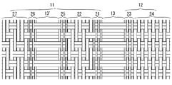
- FIG. 4 shows an example in which two or more of the third tape areas described above are provided.
- the fastener tape 10 additionally includes, in addition to the third tape area 13, at least one duplicate third tape area 13 ′ of the same tape structure.
- the third portion 83 of the weft yarn 6 extending between the first and second portions 81 and 82 of the weft yarn 6 does not have the warp yarn 4, and the first or second pitch interval j1,1. It can be understood as any area arranged at a third pitch spacing j3 equal to j2.
- the replicated third tape area 13 'illustrated in FIG. 4 may differ in lateral width from the third tape area 13 illustrated in FIG.
- a fifth sub-tape area 25 of the same tape structure as the first sub-tape area 21 is disposed between the replicated third tape area 13 ′ and the second sub-tape area 22.
- a sixth secondary tape area 26 is provided adjacent to the duplicate third tape area 13 ′ on the first side edge 1 side, and has the same tape structure as the first secondary tape area 21.
- a seventh secondary tape area 27 is provided adjacent to the sixth secondary tape area 26 on the first side edge 1 side, and has a twill tape structure.
- the tape structure of the secondary tape area included in the first tape area 11 or the second tape area 12 is not limited to the combination shown and described, and various combinations are possible. In some cases, the entire first tape area 11 is twill weave tape tissue and / or the entire second tape area 12 is twill weave tape tissue.
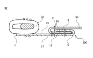
- the fastener tape 10 can be bent at the third tape area 13 to arrange the second tape area 12 on the first tape area 11.
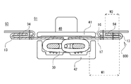
- the fastener tape 10 has a folded portion 800 bent and folded back at the third tape area 13, and the second tape area 12 is disposed on the first tape area 11.
- An attachment portion 94 of the garment portion 93 may be disposed between the first tape area 11 and the second tape area 12 as shown in FIG. Because of the improved flexibility of the fastener tape 10 based on the third tape region 13, the attachment portion 94 of the garment portion 93 may be between the first tape region 11 and the second tape region 12 of the fastener tape 10 as shown in FIG.
- the workability of sandwiching is improved, and alternatively or additionally, the workability of stitching the fastener tape 10 and the garment portion 93 is also improved.
- the fastener tape 10 covers the attachment portion 94 of the garment portion 93 without using the bias tape 900, and the exposure of the attachment portion 94 of the garment portion 93 is avoided or suppressed without relying on the bias tape 900.
- the omission of the bias tape 900 reduces the weight of the clothes.
- the third portions 83 extending in the lateral direction are arranged at a constant pitch interval j 3 in the longitudinal direction, which gives directionality to bending of the fastener tape 10.
- FIG. 7 discloses a garment including the slide fastener 91 described above and a garment portion 93 to which the slide fastener 91 is sewn.
- the garment portion 93 and the fastener tape 10 are sewn together with the attachment portion 94 of the garment portion 93 being sandwiched between the first tape area 11 and the second tape area 12 of the fastener tape 10.
- the garment may include any type and size coat or trousers.
- FIG. 8 shows that the garment portion 93 and the fastener tape 10 are sewn together by two longitudinally extending sutures. As compared with the case of using three threads as in the case of FIGS. 6 and 7, the shortening of the sewing process time or the weight reduction of the clothes is promoted.
- FIG. 9 shows that the fastener element 30 is disposed on the lower surface 17 of the tape and that a slider 40 suitable for this is used. In this manner, fastener element 30 may be secured at various locations on fastener tape 10. In some cases, fastener elements 30 are secured to the second tape area 12 to produce fastener stringers for concealed slide fasteners. A resin film or the like may be used to maintain the third tape area 13 in an arc-shaped curved state.
- FIG. 10 shows a method of manufacturing a garment according to the present disclosure.
- the method of manufacturing the garment includes a step of forming the folded portion 800 on the fastener tape 10 and a sewing step for stitching the fastener tape 10 and the garment. These steps may be performed at different or the same time.
- the step of forming the folded portion 800 on the fastener tape 10 may be a step of bending the fastener tape 10 in the third tape area 13 of the fastener tape 10 to form the folded portion 800 on the fastener tape 10.
- the attachment portion 94 of the garment portion 93 included in the garment is pinched between the first tape area 11 and the second tape area 12 of the fastener tape 10 in this step.
- the garment portion 93 and the fastener tape 10 are sewn together in a state in which the attachment portion 94 of the garment portion 93 included in the garment is sandwiched between the first tape area 11 and the second tape area 12 of the fastener tape 10. It is possible.
- the adoption of the fastener tape 10 according to the present disclosure enables the garment portion 93 and the fastener tape 10 to be sewn together without the bias tape 900.
Abstract
This fastener tape (10) comprises a plurality of warp yarns (4) and one or more weft yarns (6). Each of the warp yarns (4) extends so as to repetitively cross over a weft yarn (6) on the tape upper surface (16) side and then cross over a weft yarn (6) on the tape lower surface (17) side. In a first tape region (11), first portions (81), of the weft yarns (6), over which the warp yarns (4) cross, are disposed at a first pitch distance (j1). In a second tape region (12), second portions (82), of the weft yarns (6), over which the warp yarns (4) cross, are disposed at a second pitch distance (j2) that is equal to the first pitch distance (j1). In a third tape region (13) located between the first tape region (11) and the second tape region (12), third portions (83), of the weft yarns (6), in which warp yarns (4) are absent and which extend between the first and second portions (81, 82) of the weft yarn (6) are disposed at a third pitch distance (j3) that is equal to the first or second pitch distance (j1, j2).
Description
本開示は、ファスナーテープ、ファスナーストリンガー、スライドファスナー、衣類及び衣類の製造方法に関する。
The present disclosure relates to fastener tapes, fastener stringers, slide fasteners, garments and methods of making garments.
特許文献1は、一方のストリンガーのテープが噛合務歯部分を超えて他方のストリンガーのテープ面上に位置し得るスライドファスナーを開示する。同文献の第4頁第3~5行には、折り返し部の経糸密度を他の部分より粗として折り返しを容易にすることが記述されている。
Patent Document 1 discloses a slide fastener in which the tape of one stringer can be positioned on the tape surface of the other stringer beyond the meshing tooth portion. On page 4, lines 3-5 of the same document, it is described that the warp density of the folded portion is rougher than other portions to facilitate folding.
特許文献2は、手芸用に適したスライドファスナー用のテープを開示する。同文献の第3頁の下から5行目~2行目には、ジグザグ状の緯糸で区画された孔を手芸糸の通し孔として用いることが開示されている(同文献の図2も参照)。
Patent Document 2 discloses a tape for a slide fastener suitable for handicrafts. In the fifth line and the second line from the bottom of page 3 of the document, it is disclosed that holes defined by zigzag wefts are used as through holes for handicraft yarn (see also FIG. 2 of the same document). ).
本願発明者らは、ファスナーテープの屈曲に関して方向性を有するファスナーテープを提供する意義を新たに見出した。
The inventors of the present invention have newly found the meaning of providing a fastener tape having directionality with respect to the bending of the fastener tape.
本開示の一態様に係るファスナーテープは、各々が縦方向に延びる複数の経糸と、前記縦方向に直交する横方向に延びる少なくとも一つの緯糸から構成され、各経糸は、テープ上面側で前記緯糸を跨ぎ、テープ下面側で前記緯糸を跨ぐことを繰り返すように延びる、ファスナーテープであって、
前記経糸により跨がれる前記緯糸の第1部分が第1ピッチ間隔で配された第1テープ領域と、
前記経糸により跨がれる前記緯糸の第2部分が前記第1ピッチ間隔に等しい第2ピッチ間隔で配された第2テープ領域と、
前記第1テープ領域と前記第2テープ領域の間に位置する第3テープ領域を備え、
前記第3テープ領域において、前記経糸が存在せず、前記緯糸の前記第1及び第2部分間を延びる前記緯糸の第3部分が前記第1又は第2ピッチ間隔に等しい第3ピッチ間隔で配される。 The fastener tape according to an aspect of the present disclosure comprises a plurality of warps extending in the longitudinal direction and at least one weft extending in the transverse direction orthogonal to the longitudinal direction, and each warp is the weft on the upper surface side of the tape. A fastener tape extending so as to repeat straddling the weft on the lower surface side of the tape,
A first tape region in which a first portion of the weft yarn straddled by the warp yarn is disposed at a first pitch interval;
A second tape region in which a second portion of the weft yarn straddled by the warp yarn is disposed at a second pitch interval equal to the first pitch interval;
A third tape area located between the first tape area and the second tape area;
In the third tape area, the warp does not exist, and a third portion of the weft extending between the first and second portions of the weft is disposed at a third pitch interval equal to the first or second pitch interval. Be done.
幾つかの場合、前記第1乃至第3部分それぞれは、前記少なくとも一つの緯糸に含まれる、前記縦方向で隣接した一組の緯糸部分である。
In some cases, each of the first to third portions is the longitudinally adjacent set of weft portions included in the at least one weft.
幾つかの場合、前記縦方向において隣接する前記第3部分の間には、前記第1テープ領域と前記第2テープ領域の間隔に亘る横長の開口が形成され、
前記開口の縦開口幅は、前記経糸が、前記縦方向において隣接する前記緯糸の前記第1又は第2部分の間を通過するのに必要な空間に応じた幅である。 In some cases, a laterally long opening is formed between the first tape area and the second tape area between the longitudinally adjacent third portions.
The longitudinal opening width of the opening is a width corresponding to the space required for the warp to pass between the first or second portion of the adjacent weft in the longitudinal direction.
幾つかの場合、前記縦方向において隣接する前記第3部分の間には、前記第1テープ領域と前記第2テープ領域の間隔に亘る横長の開口が形成され、
前記開口の横開口幅は、前記開口の縦開口幅の2倍よりも大きい。 In some cases, a laterally long opening is formed between the first tape area and the second tape area between the longitudinally adjacent third portions.
The lateral aperture width of the aperture is greater than twice the longitudinal aperture width of the aperture.
前記開口の横開口幅は、前記開口の縦開口幅の2倍よりも大きい。 In some cases, a laterally long opening is formed between the first tape area and the second tape area between the longitudinally adjacent third portions.
The lateral aperture width of the aperture is greater than twice the longitudinal aperture width of the aperture.
幾つかの場合、前記縦方向に沿って延びる第1及び第2側縁部を更に備え、
前記第1テープ領域は、前記第2側縁部と比較して前記第1側縁部寄りに位置し、
前記第2テープ領域は、前記第1側縁部と比較して前記第2側縁部寄りに位置する。 In some cases, further comprising first and second side edges extending along the longitudinal direction,
The first tape area is located closer to the first side edge as compared to the second side edge,
The second tape area is positioned closer to the second side edge as compared to the first side edge.
幾つかの場合、前記第1テープ領域は、前記第3テープ領域に隣接した第1副テープ領域と、前記第1副テープ領域よりも前記第1側縁部寄りに配される第2副テープ領域を含み、
前記第1副テープ領域のテープ組織と前記第2副テープ領域のテープ組織が異なる。 In some cases, the first tape area may be a first secondary tape area adjacent to the third tape area, and a second secondary tape disposed closer to the first side edge than the first secondary tape area Including the region,
The tape organization of the first secondary tape area and the tape organization of the second secondary tape area are different.
幾つかの場合、前記第1副テープ領域では、前記第2副テープ領域と比較して前記経糸と前記緯糸がより高密度に織られている。
In some cases, the warp and weft yarns are woven at a higher density in the first secondary tape region as compared to the second secondary tape region.
幾つかの場合、前記第1副テープ領域は、1/1のテープ組織を有する。
In some cases, the first secondary tape area has 1/1 tape organization.
幾つかの場合、前記第1副テープ領域に含まれる前記経糸は、前記第2副テープ領域に含まれる前記経糸よりも細い。
In some cases, the warp included in the first secondary tape area is thinner than the warp included in the second secondary tape area.
幾つかの場合、前記第2テープ領域は、1/1のテープ組織を有する。
In some cases, the second tape area has 1/1 tape organization.
幾つかの場合、前記第2テープ領域は、前記第3テープ領域に隣接した第3副テープ領域と、前記第3副テープ領域よりも前記第2側縁部寄りに配される第4副テープ領域を含み、
前記第3副テープ領域のテープ組織と前記第4副テープ領域のテープ組織が異なる。 In some cases, the second tape area is a third sub-tape area adjacent to the third tape area and a fourth sub-tape disposed closer to the second side edge than the third sub-tape area Including the region,
The tape organization of the third secondary tape area and the tape organization of the fourth secondary tape area are different.
幾つかの場合、前記第3副テープ領域では、前記第4副テープ領域と比較して前記経糸と前記緯糸がより高密度に織られている。
In some cases, the warp and the weft are woven at a higher density in the third secondary tape region as compared to the fourth secondary tape region.
幾つかの場合、前記第3副テープ領域は、1/1のテープ組織を有する。
In some cases, the third secondary tape area has 1/1 tape organization.
幾つかの場合、前記第3副テープ領域に含まれる前記経糸は、前記第4副テープ領域に含まれる前記経糸よりも細い。
In some cases, the warp included in the third secondary tape area is thinner than the warp included in the fourth secondary tape area.
本開示の一態様に係るファスナーストリンガーは、上記いずれかのファスナーテープと、
前記ファスナーテープの第1側縁部に対して配されるファスナーエレメントを備える。 A fastener stringer according to one aspect of the present disclosure is any one of the above fastener tapes,
A fastener element is provided for the first side edge of the fastener tape.
前記ファスナーテープの第1側縁部に対して配されるファスナーエレメントを備える。 A fastener stringer according to one aspect of the present disclosure is any one of the above fastener tapes,
A fastener element is provided for the first side edge of the fastener tape.
幾つかの場合、前記第3テープ領域は、前記第1側縁部よりも前記第2側縁部寄りに配される。
In some cases, the third tape area is disposed closer to the second side edge than the first side edge.
本開示の一態様に係るスライドファスナーは、各々が上記のファスナーストリンガーである一対のファスナーストリンガーと、
前記一対のファスナーストリンガーを開閉するためのスライダーを備える。 A slide fastener according to an aspect of the present disclosure includes a pair of fastener stringers, each of which is the above-described fastener stringer.
A slider is provided to open and close the pair of fastener stringers.
前記一対のファスナーストリンガーを開閉するためのスライダーを備える。 A slide fastener according to an aspect of the present disclosure includes a pair of fastener stringers, each of which is the above-described fastener stringer.
A slider is provided to open and close the pair of fastener stringers.
幾つかの場合、前記ファスナーエレメントと前記第3テープ領域の間の横間隔は、前記第2テープ領域の横幅よりも大きい。
In some cases, the lateral spacing between the fastener element and the third tape area is greater than the lateral width of the second tape area.
本開示に係る衣類は、上記のスライドファスナーと、
前記スライドファスナーが縫い付けられる衣類部分を含む衣類であって、
前記衣類部分の取り付け部分が前記ファスナーテープの前記第1テープ領域と前記第2テープ領域の間で挟まれた状態で、前記衣類部分と前記ファスナーテープが縫い合わされる。 A garment according to the present disclosure comprises the above-mentioned slide fastener,
A garment comprising a garment portion to which the slide fastener is sewn.
The garment portion and the fastener tape are sewn together with the attachment portion of the garment portion sandwiched between the first tape area and the second tape area of the fastener tape.
幾つかの場合、前記縦方向に延びる少なくとも2本の縫い糸により前記衣類部分と前記ファスナーテープが縫い合わされる。
In some cases, the garment portion and the fastener tape are sewn together by the at least two longitudinally extending sutures.
本開示に係る衣類の製造方法は、上記のスライドファスナーが縫い付けられた衣類の製造方法であって、
前記ファスナーテープの前記第3テープ領域において前記ファスナーテープを屈曲させて折り返し部を形成する工程と、
前記ファスナーテープの前記第1テープ領域と前記第2テープ領域の間で前記衣類に含まれる衣類部分の取り付け部分が挟まれた状態で、前記衣類部分と前記ファスナーテープを縫い合わせる工程を含む。 A method of producing a garment according to the present disclosure is a method of producing a garment to which the above-mentioned slide fastener is sewn.
Bending the fastener tape in the third tape area of the fastener tape to form a folded portion;
And stitching the garment portion and the fastener tape in a state where the attachment portion of the garment portion included in the garment is sandwiched between the first tape area and the second tape area of the fastener tape.
本開示の一態様によれば、ファスナーテープの屈曲に関して方向性を有するファスナーテープを提供することができる。
According to one aspect of the present disclosure, it is possible to provide a fastener tape having directionality with respect to bending of the fastener tape.
以下、図1乃至図11を参照しつつ、本発明の非限定の実施形態について説明する。開示の1以上の実施形態及び実施形態に包含される各特徴は、個々に独立したものではない。当業者は、過剰説明を要せず、各実施形態及び/又は各特徴を組み合わせることができる。また、当業者は、この組み合わせによる相乗効果も理解可能である。実施形態間の重複説明は、原則的に省略する。参照図面は、発明の記述を主たる目的とするものであり、作図の便宜のために簡略化されている場合がある。
Hereinafter, non-limiting embodiments of the present invention will be described with reference to FIGS. 1 to 11. Each feature included in one or more embodiments and embodiments of the disclosure is not individually independent. Those skilled in the art can combine each embodiment and / or each feature without requiring an over description. Those skilled in the art can also understand the synergistic effects of this combination. Duplicate descriptions between the embodiments will be omitted in principle. The reference drawings are mainly for the description of the invention and may be simplified for the convenience of drawing.
以下に記述において、あるファスナーテープ及び/又は衣類の製造方法に関して記述される複数の特徴が、これらの特徴の組み合わせとして理解される他、他の特徴とは独立した個別の特徴として理解される。個別の特徴は、他の特徴との組み合わせを必須とすることなく独立した個別の特徴として理解されるが、1以上の他の個別の特徴との組み合わせとしても理解される。個別の特徴の全組み合わせを記述することは当業者には冗長である他なく、省略される。個別の特徴は、「幾つかの場合」という表現により明示される。個別の特徴は、例えば、図面に開示されたファスナーテープ及び/又は衣類の製造方法にのみ有効であるものではなく、他の様々なファスナーテープ及び/又は衣類の製造方法にも通用する普遍的な特徴として理解される。
In the following description, a plurality of features described with respect to a method of manufacturing a fastener tape and / or a garment will be understood as a combination of these features, as well as separate features independent of other features. An individual feature is understood as an independent individual feature without necessarily in combination with other features, but also as a combination with one or more other individual features. Describing all combinations of individual features is redundant as it is redundant to the person skilled in the art and is omitted. The individual features are specified by the expression "in some cases". For example, the individual features are not only effective in the method of manufacturing the fastener tape and / or the garment disclosed in the drawings, but also universally applicable to the method of manufacturing various other fastener tapes and / or the garment. It is understood as a feature.
図1に示すように、スライドファスナー91は、左右一対のファスナーストリンガー92と、左右一対のファスナーストリンガー92を開閉するためのスライダー40を有する。各ファスナーストリンガー92は、ファスナーテープ10と、ファスナーテープ10に対して設けられるファスナーエレメント30を有する。スライダー40の前進により左右一対のファスナーストリンガー92が閉じられ、スライダー40の後進により左右一対のファスナーストリンガー92が開かれる。スライダー40の前進により各ファスナーストリンガー92のファスナーエレメント30が噛み合い、スライダー40の後進により各ファスナーストリンガー92のファスナーエレメント30の噛み合いが解除される。前後方向は、スライダーの移動方向に照らして理解される。左右方向は、ファスナーストリンガー92が隣り合う方向に照らして理解される。上下方向は、前後方向及び左右方向に直交する。
As shown in FIG. 1, the slide fastener 91 has a pair of left and right fastener stringers 92 and a slider 40 for opening and closing the pair of left and right fastener stringers 92. Each fastener stringer 92 has a fastener tape 10 and a fastener element 30 provided to the fastener tape 10. The forward movement of the slider 40 closes the pair of left and right fastener stringers 92, and the backward movement of the slider 40 opens the pair of left and right fastener stringers 92. The forward movement of the sliders 40 engages the fastener elements 30 of each fastener stringer 92, and the reverse movement of the sliders 40 disengages the fastener elements 30 of each fastener stringer 92. The back and forth direction is understood in light of the direction of movement of the slider. The left-right direction is understood in light of the direction in which the fastener stringers 92 are adjacent. The up and down direction is orthogonal to the front and back direction and the left and right direction.
スライダー40は、金属製又は樹脂製スライダーであり得る。図1及び7に示す幾つかの場合、スライダー40は、上翼板41、下翼板42、及び上下方向沿いに延びて上翼板41と下翼板42を結合する連結柱(不図示)、上翼板41の左右側縁部から上下方向沿い(図示では下方)に延びる左右一対のフランジ部43、引手取付柱44、及び引手45を有する。スライダー40は、連結柱の左右に一対の前口を有し、この反対側に一つの後口を有する。スライダー40が後進する時、連結柱により噛み合い解除された左右のファスナーエレメント30それぞれが前口を介してスライダー内からスライダー外に移動する。各ファスナーストリンガー92のファスナーテープ10は、スライダー40のフランジ部43と下翼板42の間の前後方向に延びるスリットに通される。スライダー40として図示例以外の種類のスライダーが採用され得る。
The slider 40 may be a metal or resin slider. In some cases, as shown in FIGS. 1 and 7, the slider 40 extends along the upper blade 41, the lower blade 42, and the vertical direction to connect the upper blade 41 and the lower blade 42 (not shown). A pair of left and right flanges 43 extending in the vertical direction (downward in the figure) from the left and right side edges of the upper wing plate 41, a pull attachment bracket 44, and a pull 45. The slider 40 has a pair of front ports on the left and right of the connecting column, and one rear port on the opposite side. When the slider 40 moves backward, each of the left and right fastener elements 30 disengaged by the connecting column moves from inside the slider to outside the slider via the front opening. The fastener tape 10 of each fastener stringer 92 is passed through a slit extending in the front-rear direction between the flange portion 43 of the slider 40 and the lower blade 42. As the slider 40, sliders of types other than the illustrated example may be employed.
ファスナーテープ10は、一方向に長尺である。ファスナーテープ10がスライドファスナー91に含まれる場合、ファスナーテープ10の長手方向が前後方向に一致する。ファスナーテープ10は、その長手方向沿いに延びる第1及び第2側縁部1,2を有する。ファスナーテープ10がスライドファスナー91に含まれる場合、第1及び第2側縁部1,2を左右一対の側縁部と呼ぶこともできる。ファスナーエレメント30が、第1側縁部1に対して設けられる。スライドファスナー91の用途によっては、ファスナーエレメント30が、第1側縁部1に加えて第2側縁部2にも設けられる。ファスナーテープ10は、テープ上面16(図5参照)と、テープ上面16の反対側のテープ下面17(図5参照)を有する柔軟性を有する織物である。
The fastener tape 10 is long in one direction. When the fastener tape 10 is included in the slide fastener 91, the longitudinal direction of the fastener tape 10 coincides with the front-rear direction. The fastener tape 10 has first and second side edges 1 and 2 extending along its longitudinal direction. When the fastener tape 10 is included in the slide fastener 91, the first and second side edge portions 1 and 2 can also be referred to as a pair of left and right side edges. A fastener element 30 is provided for the first side edge 1. Depending on the application of the slide fastener 91, a fastener element 30 is provided on the second side edge 2 in addition to the first side edge 1. The fastener tape 10 is a flexible fabric having a tape upper surface 16 (see FIG. 5) and a tape lower surface 17 opposite the tape upper surface 16 (see FIG. 5).
ファスナーエレメント30は、幾つかの場合、モノフィラメントが前後方向に沿って螺旋状に巻かれたコイル状エレメントである。コイル状エレメントは、ファスナーテープ10の第1側縁部1に対して縫い糸により縫い付けられ得る。ファスナーエレメント30は、コイル状エレメントに限られない。ファスナーエレメント30として、樹脂エレメント又は金属エレメントが採用され得る。樹脂又は金属エレメントは、ファスナーテープ10の長手方向に一定ピッチで配列され得る。
The fastener element 30 is, in some cases, a coiled element in which monofilaments are spirally wound along the front-rear direction. The coiled element may be sewn to the first side edge 1 of the fastener tape 10 by means of a sewing thread. The fastener element 30 is not limited to a coiled element. A resin element or a metal element may be employed as the fastener element 30. The resin or metal elements may be arranged at a constant pitch in the longitudinal direction of the fastener tape 10.
各ファスナーストリンガー92は、幾つかの場合、前止め51、第1補強フィルム61、及び第2補強フィルム62の少なくとも一つを有する。前止め51は、樹脂又は金属部品であり、ファスナーエレメント30の前端位置でファスナーテープ10の第1側縁部1に対して固定される。前止め51は、スライダー40の前進を阻止し、すなわち、スライダー40の前方停止位置を定める。第1補強フィルム61は、ファスナーテープ10の前端部を補強するための樹脂フィルムである。第2補強フィルム62は、ファスナーテープ10の後端部を補強するための樹脂フィルムである。各フィルム61,62は、ファスナーテープ10のテープ上面16及び/又はテープ下面17に貼り付けられる。各フィルム61,62は、熱圧着によりファスナーテープ10に対して貼り付けられ得る。スライドファスナー91は、幾つかの場合、開離嵌装具52を更に有し、一対のファスナーストリンガー92が完全に分離可能である。
Each fastener stringer 92 comprises in some cases at least one of a front stop 51, a first reinforcement film 61, and a second reinforcement film 62. The front stop 51 is a resin or metal part, and is fixed to the first side edge 1 of the fastener tape 10 at the front end position of the fastener element 30. The front stop 51 prevents the slider 40 from moving forward, that is, defines the front stop position of the slider 40. The first reinforcing film 61 is a resin film for reinforcing the front end portion of the fastener tape 10. The second reinforcing film 62 is a resin film for reinforcing the rear end portion of the fastener tape 10. The respective films 61 and 62 are attached to the tape upper surface 16 and / or the tape lower surface 17 of the fastener tape 10. Each film 61, 62 may be attached to the fastener tape 10 by thermocompression bonding. The slide fastener 91 further comprises, in some cases, a snap fit fitting 52 so that the pair of fastener stringers 92 can be completely separated.
各ファスナーテープ10は、後述のように少なくとも第1テープ領域11、第2テープ領域12、及び第3テープ領域13を含む。換言すれば、各ファスナーテープ10は、少なくとも第1テープ領域11、第2テープ領域12、及び第3テープ領域13に区分可能である。幾つかの場合、各フィルム61,62は、第1テープ領域11に選択的に貼り付けられる。幾つかの場合、追加的に、各フィルム61,62は、第2テープ領域12にも貼り付けられる。幾つかの場合、補強フィルムが、第3テープ領域13に貼り付けられない。補強フィルムにより第3テープ領域13でのファスナーテープ10の屈曲が妨げられることが回避又は抑制される。柔軟性のある補強フィルムが第3テープ領域13に貼られる形態も想定される。
Each fastener tape 10 includes at least a first tape area 11, a second tape area 12, and a third tape area 13 as described below. In other words, each fastener tape 10 can be divided into at least a first tape area 11, a second tape area 12, and a third tape area 13. In some cases, each film 61, 62 is selectively affixed to the first tape area 11. In some cases, additionally, each film 61, 62 is also affixed to the second tape area 12. In some cases, a reinforcing film is not attached to the third tape area 13. It is avoided or suppressed that the bending of the fastener tape 10 in the third tape area 13 is prevented by the reinforcing film. It is also envisioned that a flexible reinforcing film may be applied to the third tape area 13.
幾つかの場合、ファスナーエレメント30と第3テープ領域13の間の横間隔W1は、第2テープ領域12の横幅W2よりも大きい(図5及び図9参照)。換言すれば、第2テープ領域12の横幅W2は、ファスナーエレメント30と第3テープ領域13の間の横間隔W1よりも小さい。
In some cases, the lateral spacing W1 between the fastener element 30 and the third tape area 13 is greater than the lateral width W2 of the second tape area 12 (see FIGS. 5 and 9). In other words, the width W 2 of the second tape area 12 is smaller than the width W 1 between the fastener element 30 and the third tape area 13.
図2乃至図4に示すように、ファスナーテープ10は、各々が縦方向に延びる複数の経糸4と、縦方向に直交する横方向に延びる少なくとも一つの緯糸6から構成される。各経糸4は、テープ上面16側で緯糸6を跨ぎ、テープ下面17側で緯糸6を跨ぐことを繰り返すように延びる。経糸4のうち緯糸6の上方に存在する部分を「浮き部」と呼び、経糸4のうち緯糸6の下方に存在する部分を「沈み部」と呼ぶこともできる。各経糸4は、浮き部と沈み部が交互に連続して成る。ファスナーテープ10は、経糸4により跨がれる緯糸6の第1部分81が第1ピッチ間隔j1で配された第1テープ領域11と、経糸4により跨がれる緯糸6の第2部分82が第1ピッチ間隔j1に等しい第2ピッチ間隔j2で配された第2テープ領域12と、第1テープ領域11と第2テープ領域12の間に位置する第3テープ領域13を有する。
As shown in FIGS. 2 to 4, the fastener tape 10 is composed of a plurality of warp yarns 4 extending in the longitudinal direction and at least one weft yarn 6 extending in the transverse direction orthogonal to the longitudinal direction. Each warp 4 straddles the weft 6 on the tape upper surface 16 side, and extends so as to repeatedly straddle the weft 6 on the tape lower surface 17 side. A portion of the warp 4 located above the weft 6 may be called a "floating portion", and a portion of the warp 4 located below the weft 6 may be called a "sinking portion". In each warp 4, floats and sinks are alternately and continuously formed. The fastener tape 10 has a first tape area 11 in which a first portion 81 of the weft 6 straddled by the warp 4 is disposed at a first pitch interval j1, and a second portion 82 of the weft 6 straddles by the warp 4 A second tape area 12 disposed at a second pitch interval j2 equal to one pitch interval j1 and a third tape area 13 located between the first tape area 11 and the second tape area 12 are provided.
第1テープ領域11は、テープ上面16側で緯糸6の第1部分81を跨ぎ、テープ下面17側で緯糸6の第1部分81を跨ぐことを繰り返すように延びる複数の経糸4を含む。第2テープ領域12は、テープ上面16側で緯糸6の第2部分82を跨ぎ、テープ下面17側で緯糸6の第2部分82を跨ぐことを繰り返すように延びる複数の経糸4を含む。緯糸6の第1部分81は、第1テープ領域11に属する緯糸6の部分として理解され得る。緯糸6の第2部分82は、第2テープ領域12に属する緯糸6の部分として理解され得る。
The first tape area 11 straddles the first portion 81 of the weft yarn 6 on the tape upper surface 16 side, and includes a plurality of warp yarns 4 extending repeatedly so as to straddle the first portion 81 of the weft yarn 6 on the tape lower surface 17 side. The second tape region 12 includes a plurality of warp yarns 4 extending repeatedly so as to straddle the second portion 82 of the weft 6 on the tape upper surface 16 side and straddle the second portion 82 of the weft 6 on the tape lower surface 17 side. The first portion 81 of the weft yarn 6 can be understood as the portion of the weft yarn 6 belonging to the first tape area 11. The second portion 82 of the weft yarn 6 can be understood as the portion of the weft yarn 6 belonging to the second tape area 12.
第1テープ領域11は、第2側縁部2と比較して第1側縁部1寄りに位置する。第2テープ領域12は、第1側縁部1と比較して第2側縁部2寄りに位置する。必ずしもこの限りではないが、第3テープ領域13は、第1側縁部1よりも第2側縁部2寄りに位置する。幾つかの場合、第1側縁部1が第1テープ領域11に含まれ、及び/又は、第2側縁部2が第2テープ領域12に含まれる。幾つかの場合、第1側縁部1が、第1テープ領域11とは異なるテープ組織のテープ領域に含まれ、及び/又は、第2側縁部2が、第2テープ領域12とは異なるテープ組織のテープ領域に含まれる。
The first tape area 11 is located closer to the first side edge 1 compared to the second side edge 2. The second tape area 12 is located closer to the second side edge 2 compared to the first side edge 1. Although not necessarily limited to this, the third tape area 13 is located closer to the second side edge 2 than the first side edge 1. In some cases, the first side edge 1 is included in the first tape area 11 and / or the second side edge 2 is included in the second tape area 12. In some cases, the first side edge 1 is included in the tape area of the tape tissue different from the first tape area 11 and / or the second side edge 2 is different from the second tape area 12 Included in the tape area of the tape tissue.
第3テープ領域13において、経糸4が存在せず、緯糸6の第1及び第2部分81,82間を延びる緯糸6の第3部分83が第1又は第2ピッチ間隔j1,j2に等しい第3ピッチ間隔j3で配される。幾つかの場合、第3テープ領域13は、第3ピッチ間隔j3の第3部分83のみで構成される。これにより、ファスナーテープ10の屈曲に関して方向性を有するファスナーテープ10が提供される。必ずしもこの限りではないが、図5に示すようにファスナーテープ10に折り返し部800を形成することが促進される。
In the third tape region 13, there is no warp yarn 4, and a third portion 83 of the weft yarn 6 extending between the first and second portions 81, 82 of the weft yarn 6 is equal to the first or second pitch interval j1, j2. Three pitches j3 are provided. In some cases, the third tape area 13 comprises only the third portion 83 of the third pitch interval j3. Thereby, the fastener tape 10 having directivity with respect to the bending of the fastener tape 10 is provided. Although not necessarily limited to this, as shown in FIG. 5, the formation of the folded back portion 800 on the fastener tape 10 is promoted.
経糸4が存在しない第3テープ領域13では、縦方向において隣接する第3部分83の間には、第1テープ領域11と第2テープ領域12の間隔に亘る横長の開口9が形成される。幾つかの場合、緯糸6が複数のより細い糸を含んで構成され、又は複数のより細い糸が撚られて成る。緯糸6の第3部分83が、経糸4により拘束されない結果、縦方向に膨らみを有し得る。この結果、緯糸6の第3部分83により横長の開口9が全体的又は部分的に閉じられる。しかしながら、このような場合においても、テープ組織の構成の見地からは、第3部分83の間に横長の開口9が形成されているものと理解される。
In the third tape area 13 in which the warp yarns 4 do not exist, a horizontally long opening 9 is formed between the third tape section 83 adjacent in the longitudinal direction, extending between the first tape area 11 and the second tape area 12. In some cases, the weft yarn 6 comprises a plurality of thinner yarns, or a plurality of thinner yarns are twisted. As a result of the fact that the third portion 83 of the weft thread 6 is not restrained by the warp threads 4, it can have a bulge in the longitudinal direction. As a result, the horizontally long opening 9 is totally or partially closed by the third portion 83 of the weft 6. However, even in such a case, it is understood from the viewpoint of the configuration of the tape tissue that the laterally long opening 9 is formed between the third portions 83.
横長の開口9の縦開口幅V9は、第1テープ領域11と第2テープ領域12の間隔に亘り一定であり得る。このことは、緯糸6の第3部分83が第3ピッチ間隔j3で配置されることの帰結として理解され得る。開口9の縦開口幅V9は、緯糸6の第3部分83の膨らみにより変動し得る。すなわち、第3部分83の膨らみに応じた横方向における開口幅V9の変動が予期される。開口9の縦開口幅V9は、経糸4が、縦方向において隣接する緯糸6の第1又は第2部分81,82の間を通過するのに必要な空間に応じた幅である。幾つかの場合、ファスナーテープ10が左右に横引きされ、各第3部分83が縦方向に膨らむこと無く左右方向に平行に延びた状態において開口9の縦開口幅V9が観察される。
The longitudinal opening width V9 of the horizontal opening 9 may be constant over the distance between the first tape area 11 and the second tape area 12. This can be understood as a consequence of the third portion 83 of the weft 6 being arranged at the third pitch interval j3. The longitudinal opening width V9 of the opening 9 may vary due to the expansion of the third portion 83 of the weft 6. That is, fluctuation of the opening width V9 in the lateral direction according to the swelling of the third portion 83 is expected. The longitudinal opening width V9 of the opening 9 is a width corresponding to the space required for the warp yarn 4 to pass between the first or second portions 81, 82 of the adjacent weft yarns 6 in the longitudinal direction. In some cases, the longitudinal opening width V9 of the opening 9 is observed in a state in which the fastener tape 10 is horizontally drawn in the lateral direction and each third portion 83 extends in parallel in the lateral direction without swelling in the longitudinal direction.
開口9の横開口幅L9は、幾つかの場合、0.3mm以上である。追加的又は代替的に、開口9の横開口幅L9は、幾つかの場合、2.6mm以下である。図示例を含む幾つかの場合、開口9は、横長の矩形状の開口である。第1テープ領域11に対する第2テープ領域12の相対的な位置に応じて開口9の開口形状が変化し得る。例えば、第1テープ領域11よりも第2テープ領域12が前方にずらされる時、第3部分83が斜めに延び、開口9が斜めに延びた開口形状になる。
The lateral opening width L9 of the opening 9 is in some cases 0.3 mm or more. Additionally or alternatively, the lateral opening width L9 of the opening 9 is in some cases less than or equal to 2.6 mm. In some cases, including the illustrated example, the opening 9 is a horizontally long rectangular opening. Depending on the relative position of the second tape area 12 to the first tape area 11, the opening shape of the opening 9 may change. For example, when the second tape area 12 is shifted forward with respect to the first tape area 11, the third portion 83 obliquely extends, and the opening 9 has an obliquely extending opening shape.
第3テープ領域13は、緯糸6の第3部分83が第3ピッチ間隔j3で配された領域であり、テープ上面16側で緯糸6の第3部分83を跨ぎ、テープ下面17側で緯糸6の第3部分83を跨ぐことを繰り返すように延びる経糸4を有しない。幾つかの場合、第3テープ領域13は、複数の水溶性の経糸(不図示)を有する。水溶性の経糸は、テープ上面16側で緯糸6の第3部分83を跨ぎ、テープ下面17側で緯糸6の第3部分83を跨ぐことを繰り返すように延びる。緯糸6の第3部分83は、第3テープ領域13に属する緯糸6の部分として理解され得る。水溶性の経糸を用いることにより、既存の織機をそのまま用いて本開示に係るファスナーテープ10を製造することができる。
The third tape area 13 is an area in which the third portions 83 of the weft yarns 6 are arranged at the third pitch interval j 3, straddles the third portions 83 of the weft yarns 6 on the tape upper surface 16 side, and the weft yarns 6 on the tape lower surface 17 side. There is no warp 4 extending to repeat straddling the third portion 83 of the. In some cases, the third tape area 13 comprises a plurality of water soluble warp yarns (not shown). The water-soluble warp extends across the third portion 83 of the weft 6 on the tape upper surface 16 side and repeatedly straddles the third portion 83 of the weft 6 on the tape lower surface 17 side. The third portion 83 of the weft yarn 6 can be understood as the portion of the weft yarn 6 belonging to the third tape area 13. By using a water-soluble warp, the fastener tape 10 according to the present disclosure can be manufactured using an existing loom as it is.
第1~第3部分81,82,83それぞれは、少なくとも一つの緯糸6に含まれる、縦方向で隣接した一組の緯糸部分7であり得る。緯糸部分7は、横方向に延びる部分である。幾つかの場合、少なくとも一つの緯糸6は、一つのファスナーテープ10において横方向の両端で折り返される。幾つかの場合、横方向で反対方向に延びる緯糸6の一組の部分と経糸が織られる。これは、織機がファスナーテープ10を織る時、緯糸6が、横方向の第1方向に引かれ、続いて緯糸6が横方向の第1方向の反対の第2方向に引かれることの結果であり得る。
Each of the first to third portions 81, 82, 83 may be a longitudinally adjacent set of weft yarn portions 7 included in at least one weft yarn 6. The weft yarn portion 7 is a portion extending in the lateral direction. In some cases, at least one weft yarn 6 is folded back at both ends in one fastener tape 10. In some cases, wefts are woven with a set of portions of weft yarn 6 extending in the transversely opposite direction. This is because, when the loom weaves the fastener tape 10, the weft yarn 6 is drawn in the first lateral direction, and then the weft yarn 6 is drawn in the second direction opposite to the first lateral direction. possible.
第1ピッチ間隔j1は、経糸4により跨がれる緯糸6の第1部分81の縦方向幅よりも大きい。第2ピッチ間隔j2は、経糸4により跨がれる緯糸6の第2部分82の縦方向幅よりも大きい。第3ピッチ間隔j3は、緯糸6の第3部分83の縦方向幅よりも大きい。第1~第3ピッチ間隔j1,j2,j3それぞれは、一組の緯糸部分7の縦方向の中心点の間隔として定義され得る。図2に例示のように、ピッチ間隔は、ピッチ間隔j2’,j2’’のように縦方向においてシフトして理解され得る。
The first pitch interval j 1 is larger than the longitudinal width of the first portion 81 of the weft yarn 6 straddled by the warp yarn 4. The second pitch interval j 2 is larger than the longitudinal width of the second portion 82 of the weft yarn 6 straddled by the warp yarn 4. The third pitch interval j3 is larger than the longitudinal width of the third portion 83 of the weft 6. Each of the first to third pitch intervals j1, j2, j3 may be defined as an interval of the longitudinal center points of the pair of weft yarn portions 7. As illustrated in FIG. 2, the pitch spacing may be understood to be shifted in the longitudinal direction, such as pitch spacing j2 ', j2' '.
図2及び図3に示すように、第1テープ領域11は、第3テープ領域13に隣接した第1副テープ領域21と、第1副テープ領域21よりも第1側縁部1寄りに設けられる第2副テープ領域22を含み得る。図2を含む幾つかの場合、第1副テープ領域21のテープ組織と第2副テープ領域22のテープ組織が異なる。第1副テープ領域21では、経糸4は、テープ上面16側で一つの第1部分81を跨ぎ、テープ下面17側で一つの第1部分81を跨ぐことを繰り返すように延びる。他方、第2副テープ領域22では、経糸4は、テープ上面16側で2つの第1部分81を跨ぎ、テープ下面17側で2つの第1部分81を跨ぐことを繰り返すように延びる。第2副テープ領域22では、テープ上面16又はテープ下面17に露出する経糸4の部分が斜め方向にシフトして配される。一例として、第1副テープ領域21が、1/1のテープ組織を有し、第2副テープ領域22が、綾織のテープ組織を有する。なお、1/1のテープ組織に関して、一組の緯糸部分7が一本の緯糸であるものと捉えられている。第1副テープ領域21では、第2副テープ領域22と比較して経糸4と緯糸6がより高密度に織られている。これにより、接着剤を使用することなく、及び/又は、経糸4と緯糸6を固着することなく、第1テープ領域11における経糸4が第3テープ領域13側に動いてしまうことが回避又は抑制される。
As shown in FIGS. 2 and 3, the first tape area 11 is provided closer to the first side edge 1 than the first sub tape area 21 adjacent to the third tape area 13 and the first sub tape area 21. May include a second secondary tape area 22. In some cases, including FIG. 2, the tape organization of the first secondary tape area 21 and the tape organization of the second secondary tape area 22 are different. In the first sub-tape region 21, the warp 4 straddles one first portion 81 on the tape upper surface 16 side, and extends so as to repeat straddling one first portion 81 on the tape lower surface 17 side. On the other hand, in the second sub-tape region 22, the warp yarn 4 extends so as to straddle the two first portions 81 on the tape upper surface 16 side and repeatedly straddle the two first portions 81 on the tape lower surface 17 side. In the second sub-tape region 22, the portion of the warp 4 exposed to the tape upper surface 16 or the tape lower surface 17 is shifted in an oblique direction. As an example, the first secondary tape area 21 has 1/1 tape structure, and the second secondary tape area 22 has twill tape structure. In addition, regarding the 1/1 tape structure, it is considered that one set of weft yarn portion 7 is one weft yarn. In the first sub-tape region 21, the warp yarns 4 and the weft yarns 6 are woven at a higher density than the second sub-tape region 22. Thus, the warp 4 in the first tape area 11 is prevented from moving to the third tape area 13 side without using an adhesive and / or without fixing the warp 4 and the weft 6. Be done.
図3を含む幾つかの場合、第1副テープ領域21のテープ組織と第2副テープ領域22のテープ組織が同一である。第1副テープ領域21では、経糸4は、テープ上面16側で2つの第1部分81を跨ぎ、テープ下面17側で2つの第1部分81を跨ぐことを繰り返すように延びる。第2副テープ領域22では、経糸4は、テープ上面16側で2つの第1部分81を跨ぎ、テープ下面17側で2つの第1部分81を跨ぐことを繰り返すように延びる。第1及び第2副テープ領域21,22では、テープ上面16又はテープ下面17に露出する経糸4の部分が斜め方向にシフトして配される。一例として、第1副テープ領域21と第2副テープ領域22が、綾織のテープ組織を有する。
In some cases, including FIG. 3, the tape organization of the first secondary tape area 21 and the tape organization of the second secondary tape area 22 are identical. In the first sub-tape region 21, the warp 4 straddles the two first portions 81 on the tape upper surface 16 side, and extends so as to repeatedly straddle the two first portions 81 on the tape lower surface 17 side. In the second sub-tape region 22, the warp 4 straddles the two first portions 81 on the tape upper surface 16 side, and extends so as to repeatedly straddle the two first portions 81 on the tape lower surface 17 side. In the first and second sub-tape regions 21 and 22, the portion of the warp 4 exposed to the tape upper surface 16 or the tape lower surface 17 is shifted in an oblique direction. As an example, the first secondary tape area 21 and the second secondary tape area 22 have twill tape structure.
第2テープ領域12は、第3テープ領域13に隣接した第3副テープ領域23と、第3副テープ領域23よりも第2側縁部2寄りに設けられる第4副テープ領域24を含む。第2テープ領域12は、1/1のテープ組織を有し得る。幾つかの場合、第3副テープ領域23のテープ組織と第4副テープ領域24のテープ組織が同一であり、又は異なる。図2を含む幾つかの場合、第3副テープ領域23のテープ組織と第4副テープ領域24のテープ組織が同一であり、1/1のテープ組織を有する。第3副テープ領域23では、第4副テープ領域24と比較して経糸4がより高密度に織り込まれている。第3及び第4副テープ領域23,24は、1/1のテープ組織を有する。図3を含む幾つかの場合、第3副テープ領域23のテープ組織と第4副テープ領域24のテープ組織が異なる。第1テープ領域11の第1副テープ領域21と第2副テープ領域22について説明したものと同様の説明が、第2副テープ領域22の第3副テープ領域23と第4副テープ領域24にも当てはまり、重複説明は省略する。
The second tape area 12 includes a third secondary tape area 23 adjacent to the third tape area 13 and a fourth secondary tape area 24 provided closer to the second side edge 2 than the third secondary tape area 23. The second tape area 12 may have a 1/1 tape organization. In some cases, the tape organization of the third secondary tape area 23 and the tape organization of the fourth secondary tape area 24 are identical or different. In some cases, including FIG. 2, the tape system of the third minor tape area 23 and the tape system of the fourth minor tape area 24 are identical and have 1/1 tape system. In the third secondary tape area 23, the warp yarns 4 are woven in at a higher density as compared with the fourth secondary tape area 24. The third and fourth secondary tape areas 23, 24 have a 1/1 tape structure. In some cases, including FIG. 3, the tape organization of the third secondary tape area 23 and the tape organization of the fourth secondary tape area 24 are different. The same description as described for the first sub tape area 21 and the second sub tape area 22 of the first tape area 11 applies to the third sub tape area 23 and the fourth sub tape area 24 of the second sub tape area 22. The same applies, and duplicate explanations are omitted.
必ずしもこの限りではないが、第1副テープ領域21に含まれる経糸4は、第2副テープ領域22に含まれる経糸4よりも細い。追加的又は代替的に、第3副テープ領域23に含まれる経糸4は、第4副テープ領域24に含まれる経糸4よりも細い。これにより、接着剤を使用することなく、及び/又は、経糸4と緯糸6を固着することなく、第1テープ領域11における経糸4が第3テープ領域13側に動いてしまうことが回避又は抑制される。
Although not necessarily limited to this, the warp yarn 4 included in the first sub-tape region 21 is thinner than the warp yarn 4 included in the second sub-tape region 22. Additionally or alternatively, the warp yarns 4 contained in the third sub-tape region 23 are thinner than the warp yarns 4 contained in the fourth sub-tape region 24. Thus, the warp 4 in the first tape area 11 is prevented from moving to the third tape area 13 side without using an adhesive and / or without fixing the warp 4 and the weft 6. Be done.
図4は、上述した第3テープ領域が2以上設けられる例を示す。図4に示すように、ファスナーテープ10は、第3テープ領域13に加えて、これと同一のテープ組織の少なくとも一つの複製第3テープ領域13’を追加として含む。なお、複製第3テープ領域13’は、経糸4が存在せず、緯糸6の第1及び第2部分81,82間を延びる緯糸6の第3部分83が第1又は第2ピッチ間隔j1,j2に等しい第3ピッチ間隔j3で配される任意の領域として理解される。図4に図示の複製第3テープ領域13’は、図4に図示の第3テープ領域13と横方向幅が異なり得る。複製第3テープ領域13’と第2副テープ領域22の間には第1副テープ領域21と同一のテープ組織の第5副テープ領域25が配される。複製第3テープ領域13’に対して第1側縁部1側で隣接して第6副テープ領域26が設けられ、これは、第1副テープ領域21と同一のテープ組織を有する。第6副テープ領域26に対して第1側縁部1側で隣接して第7副テープ領域27が設けられ、これは、綾織のテープ組織を有する。第1テープ領域11又は第2テープ領域12に含まれる副テープ領域のテープ組織については、図示及び記述した組み合わせに限らず、様々な組み合わせが可能である。幾つかの場合、第1テープ領域11の全体が綾織のテープ組織であり、及び/又は、第2テープ領域12の全体が綾織のテープ組織である。
FIG. 4 shows an example in which two or more of the third tape areas described above are provided. As shown in FIG. 4, the fastener tape 10 additionally includes, in addition to the third tape area 13, at least one duplicate third tape area 13 ′ of the same tape structure. In the replicated third tape region 13 ', the third portion 83 of the weft yarn 6 extending between the first and second portions 81 and 82 of the weft yarn 6 does not have the warp yarn 4, and the first or second pitch interval j1,1. It can be understood as any area arranged at a third pitch spacing j3 equal to j2. The replicated third tape area 13 'illustrated in FIG. 4 may differ in lateral width from the third tape area 13 illustrated in FIG. A fifth sub-tape area 25 of the same tape structure as the first sub-tape area 21 is disposed between the replicated third tape area 13 ′ and the second sub-tape area 22. A sixth secondary tape area 26 is provided adjacent to the duplicate third tape area 13 ′ on the first side edge 1 side, and has the same tape structure as the first secondary tape area 21. A seventh secondary tape area 27 is provided adjacent to the sixth secondary tape area 26 on the first side edge 1 side, and has a twill tape structure. The tape structure of the secondary tape area included in the first tape area 11 or the second tape area 12 is not limited to the combination shown and described, and various combinations are possible. In some cases, the entire first tape area 11 is twill weave tape tissue and / or the entire second tape area 12 is twill weave tape tissue.
図5に示すようにファスナーテープ10を第3テープ領域13で屈曲させて第1テープ領域11上に第2テープ領域12を配置することができる。ファスナーテープ10は、第3テープ領域13で屈曲して折り返された折り返し部800を有し、第1テープ領域11上に第2テープ領域12が配される。第1テープ領域11と第2テープ領域12の間には図6に示すように衣類部分93の取り付け部分94が配され得る。第3テープ領域13に基づく改善されたファスナーテープ10の屈曲性のため、図6に示すように衣類部分93の取り付け部分94をファスナーテープ10の第1テープ領域11と第2テープ領域12の間で挟む作業性が改善され、代替的又は追加的に、ファスナーテープ10と衣類部分93の縫い合わせの作業性も改善される。
As shown in FIG. 5, the fastener tape 10 can be bent at the third tape area 13 to arrange the second tape area 12 on the first tape area 11. The fastener tape 10 has a folded portion 800 bent and folded back at the third tape area 13, and the second tape area 12 is disposed on the first tape area 11. An attachment portion 94 of the garment portion 93 may be disposed between the first tape area 11 and the second tape area 12 as shown in FIG. Because of the improved flexibility of the fastener tape 10 based on the third tape region 13, the attachment portion 94 of the garment portion 93 may be between the first tape region 11 and the second tape region 12 of the fastener tape 10 as shown in FIG. The workability of sandwiching is improved, and alternatively or additionally, the workability of stitching the fastener tape 10 and the garment portion 93 is also improved.
衣類部分93の取り付け部分94とファスナーテープ10の縫い合わせに際して、さもなければ必要になるバイアステープ900(図11参照)を省略することも促進され得る。バイアステープ900を用いることなくファスナーテープ10により衣類部分93の取り付け部分94が被覆され、バイアステープ900に頼ることなく衣類部分93の取り付け部分94の露出が回避又は抑制される。バイアステープ900の省略により衣類が軽量化される。なお、第3テープ領域13では横方向に延びる第3部分83が縦方向に一定のピッチ間隔j3で配列され、ファスナーテープ10の屈曲に方向性を与える。
It may also be facilitated to omit the bias tape 900 (see FIG. 11) that would otherwise be required when stitching the attachment portion 94 of the garment portion 93 and the fastener tape 10. The fastener tape 10 covers the attachment portion 94 of the garment portion 93 without using the bias tape 900, and the exposure of the attachment portion 94 of the garment portion 93 is avoided or suppressed without relying on the bias tape 900. The omission of the bias tape 900 reduces the weight of the clothes. In the third tape area 13, the third portions 83 extending in the lateral direction are arranged at a constant pitch interval j 3 in the longitudinal direction, which gives directionality to bending of the fastener tape 10.
図7は、上述のスライドファスナー91と、スライドファスナー91が縫い付けられる衣類部分93を含む衣類を開示する。衣類部分93の取り付け部分94がファスナーテープ10の第1テープ領域11と第2テープ領域12の間で挟まれた状態で、衣類部分93とファスナーテープ10が縫い合わされる。衣類は、任意の種類及びサイズの上着やズボンを含み得る。
FIG. 7 discloses a garment including the slide fastener 91 described above and a garment portion 93 to which the slide fastener 91 is sewn. The garment portion 93 and the fastener tape 10 are sewn together with the attachment portion 94 of the garment portion 93 being sandwiched between the first tape area 11 and the second tape area 12 of the fastener tape 10. The garment may include any type and size coat or trousers.
図8は、縦方向に延びる2本の縫い糸により衣類部分93とファスナーテープ10が縫い合わされることを示す。図6及び図7の場合のように3本の縫い糸を用いる場合よりも縫い合わせ工程の時間の短縮化又は衣類の軽量化が促進される。
FIG. 8 shows that the garment portion 93 and the fastener tape 10 are sewn together by two longitudinally extending sutures. As compared with the case of using three threads as in the case of FIGS. 6 and 7, the shortening of the sewing process time or the weight reduction of the clothes is promoted.
図9は、ファスナーエレメント30がテープ下面17に配され、またこれに適したスライダー40が用いられることを示す。このようにファスナーエレメント30は、ファスナーテープ10において様々な場所に固定され得る。幾つかの場合、ファスナーエレメント30を第2テープ領域12に固定され、隠しスライドファスナー用のファスナーストリンガーが製造される。第3テープ領域13を弧状に湾曲した状態に維持するために樹脂フィルム等が用いられ得る。
FIG. 9 shows that the fastener element 30 is disposed on the lower surface 17 of the tape and that a slider 40 suitable for this is used. In this manner, fastener element 30 may be secured at various locations on fastener tape 10. In some cases, fastener elements 30 are secured to the second tape area 12 to produce fastener stringers for concealed slide fasteners. A resin film or the like may be used to maintain the third tape area 13 in an arc-shaped curved state.
図10は、本開示に係る衣類の製造方法を示す。この衣類の製造方法は、ファスナーテープ10に折り返し部800を形成する工程と、ファスナーテープ10と衣類の縫い合わせるための縫製工程を含む。これらの工程が、異なる又は同一の時間に行われ得る。ファスナーテープ10に折り返し部800を形成する工程は、ファスナーテープ10の第3テープ領域13においてファスナーテープ10を屈曲させてファスナーテープ10に折り返し部800を形成する工程であり得る。必ずしもこの限りではないが、幾つかの場合、この工程において、ファスナーテープ10の第1テープ領域11と第2テープ領域12の間で衣類に含まれる衣類部分93の取り付け部分94が挟まれる。縫製工程は、ファスナーテープ10の第1テープ領域11と第2テープ領域12の間で衣類に含まれる衣類部分93の取り付け部分94が挟まれた状態で、衣類部分93とファスナーテープ10を縫い合わせる工程で有り得る。本開示に係るファスナーテープ10の採用によりバイアステープ900無しで衣類部分93とファスナーテープ10を縫い合わせることが可能になる。
FIG. 10 shows a method of manufacturing a garment according to the present disclosure. The method of manufacturing the garment includes a step of forming the folded portion 800 on the fastener tape 10 and a sewing step for stitching the fastener tape 10 and the garment. These steps may be performed at different or the same time. The step of forming the folded portion 800 on the fastener tape 10 may be a step of bending the fastener tape 10 in the third tape area 13 of the fastener tape 10 to form the folded portion 800 on the fastener tape 10. In some cases, but not necessarily, the attachment portion 94 of the garment portion 93 included in the garment is pinched between the first tape area 11 and the second tape area 12 of the fastener tape 10 in this step. In the sewing step, the garment portion 93 and the fastener tape 10 are sewn together in a state in which the attachment portion 94 of the garment portion 93 included in the garment is sandwiched between the first tape area 11 and the second tape area 12 of the fastener tape 10. It is possible. The adoption of the fastener tape 10 according to the present disclosure enables the garment portion 93 and the fastener tape 10 to be sewn together without the bias tape 900.
上述の教示を踏まえると、当業者をすれば、各実施形態に対して様々な変更を加えることができる。請求の範囲に盛り込まれた符号は、参考のためであり、請求の範囲を限定解釈する目的で参照されるべきものではない。
Given the above teachings, various modifications can be made to the embodiments by those skilled in the art. The reference numerals included in the claims are for reference and should not be referred to for the purpose of limiting the scope of the claims.
4 経糸
6 緯糸
9 開口
10 ファスナーテープ
11 第1テープ領域
12 第2テープ領域
13 第3テープ領域
16 テープ上面
17 テープ下面
81 第1部分
82 第2部分
83 第3部分
j1 第1ピッチ間隔
j2 第2ピッチ間隔
j3 第3ピッチ間隔
V9 縦開口幅 4 warp yarn 6weft yarn 9 opening 10 fastener tape 11 first tape area 12 second tape area 13 third tape area 16 tape upper surface 17 tape lower surface 81 first portion 82 second portion 83 third portion j1 first pitch interval j2 second Pitch spacing j3 Third pitch spacing V9 Vertical aperture width
6 緯糸
9 開口
10 ファスナーテープ
11 第1テープ領域
12 第2テープ領域
13 第3テープ領域
16 テープ上面
17 テープ下面
81 第1部分
82 第2部分
83 第3部分
j1 第1ピッチ間隔
j2 第2ピッチ間隔
j3 第3ピッチ間隔
V9 縦開口幅 4 warp yarn 6
Claims (21)
- 各々が縦方向に延びる複数の経糸(4)と、前記縦方向に直交する横方向に延びる少なくとも一つの緯糸(6)から構成され、各経糸(4)は、テープ上面(16)側で前記緯糸(6)を跨ぎ、テープ下面(17)側で前記緯糸(6)を跨ぐことを繰り返すように延びる、ファスナーテープ(10)であって、
前記経糸(4)により跨がれる前記緯糸(6)の第1部分(81)が第1ピッチ間隔(j1)で配された第1テープ領域(11)と、
前記経糸(4)により跨がれる前記緯糸(6)の第2部分(82)が前記第1ピッチ間隔(j1)に等しい第2ピッチ間隔(j2)で配された第2テープ領域(12)と、
前記第1テープ領域(11)と前記第2テープ領域(12)の間に位置する第3テープ領域(13)を備え、
前記第3テープ領域(13)において、前記経糸(4)が存在せず、前記緯糸(6)の前記第1及び第2部分(81,82)間を延びる前記緯糸(6)の第3部分(83)が前記第1又は第2ピッチ間隔(j1,j2)に等しい第3ピッチ間隔(j3)で配される、ファスナーテープ。 It comprises a plurality of warps (4) each extending in the longitudinal direction and at least one weft (6) extending in the transverse direction orthogonal to the longitudinal direction, each warp (4) being on the tape upper surface (16) side A fastener tape (10) which straddles a weft (6) and repeatedly repeats straddling the weft (6) on the tape lower surface (17) side,
A first tape area (11) in which a first portion (81) of the weft (6) straddled by the warp (4) is arranged at a first pitch interval (j1);
A second tape area (12) in which a second portion (82) of the weft (6) straddled by the warp (4) is arranged at a second pitch interval (j2) equal to the first pitch interval (j1) When,
A third tape area (13) located between the first tape area (11) and the second tape area (12);
In the third tape region (13), the third portion of the weft (6) does not have the warp (4) and extends between the first and second portions (81, 82) of the weft (6) A fastener tape, wherein (83) is disposed at a third pitch interval (j3) equal to the first or second pitch interval (j1, j2). - 前記第1乃至第3部分(81,82,83)それぞれは、前記少なくとも一つの緯糸(6)に含まれる、前記縦方向で隣接した一組の緯糸部分(7)である、請求項1に記載のファスナーテープ。 The first to third portions (81, 82, 83) are each a pair of weft portions (7) adjacent to each other in the longitudinal direction included in the at least one weft (6). Fastener tape described.
- 前記縦方向において隣接する前記第3部分(83)の間には、前記第1テープ領域(11)と前記第2テープ領域(12)の間隔に亘る横長の開口(9)が形成され、
前記開口(9)の縦開口幅(V9)は、前記経糸(4)が、前記縦方向において隣接する前記緯糸(6)の前記第1又は第2部分(81,82)の間を通過するのに必要な空間に応じた幅である、請求項1又は2に記載のファスナーテープ。 A horizontally long opening (9) is formed between the third tape portion (83) adjacent in the longitudinal direction, the space extending between the first tape region (11) and the second tape region (12).
The longitudinal opening width (V9) of the opening (9) is such that the warp yarn (4) passes between the first or second portion (81 82) of the weft yarn (6) adjacent in the longitudinal direction The fastener tape according to claim 1 or 2, which has a width corresponding to the space required for. - 前記縦方向において隣接する前記第3部分(83)の間には、前記第1テープ領域(11)と前記第2テープ領域(12)の間隔に亘る横長の開口(9)が形成され、
前記開口(9)の横開口幅(L9)は、前記開口(9)の縦開口幅(V9)の2倍よりも大きい、請求項1乃至3のいずれか一項に記載のファスナーテープ。 A horizontally long opening (9) is formed between the third tape portion (83) adjacent in the longitudinal direction, the space extending between the first tape region (11) and the second tape region (12).
The fastener tape according to any one of claims 1 to 3, wherein a lateral opening width (L9) of the opening (9) is larger than twice a vertical opening width (V9) of the opening (9). - 前記縦方向に沿って延びる第1及び第2側縁部(1,2)を更に備え、
前記第1テープ領域(11)は、前記第2側縁部(2)と比較して前記第1側縁部(1)寄りに位置し、
前記第2テープ領域(12)は、前記第1側縁部(1)と比較して前記第2側縁部(2)寄りに位置する、請求項1乃至4のいずれか一項に記載のファスナーテープ。 It further comprises first and second side edges (1, 2) extending along said longitudinal direction,
The first tape area (11) is positioned closer to the first side edge (1) compared to the second side edge (2),
The second tape area (12) is located closer to the second side edge (2) compared to the first side edge (1). Fastener tape. - 前記第1テープ領域(11)は、前記第3テープ領域(13)に隣接した第1副テープ領域(21)と、前記第1副テープ領域(21)よりも前記第1側縁部(1)寄りに配される第2副テープ領域(22)を含み、
前記第1副テープ領域(21)のテープ組織と前記第2副テープ領域(22)のテープ組織が異なる、請求項5に記載のファスナーテープ。 The first tape area (11) comprises a first sub-tape area (21) adjacent to the third tape area (13) and the first side edge (1) than the first sub-tape area (21). A second secondary tape area (22) disposed closer to the
The fastener tape according to claim 5, wherein the tape system of the first secondary tape area (21) and the tape system of the second secondary tape area (22) are different. - 前記第1副テープ領域(21)では、前記第2副テープ領域(22)と比較して前記経糸(4)と前記緯糸(6)がより高密度に織られている、請求項6に記載のファスナーテープ。 The first secondary tape region (21) according to claim 6, wherein the warp yarn (4) and the weft yarn (6) are woven at a higher density than the second secondary tape region (22). Fastener tape.
- 前記第1副テープ領域(21)は、1/1のテープ組織を有する、請求項6又は7に記載のファスナーテープ。 The fastener tape according to claim 6 or 7, wherein the first secondary tape area (21) has a 1/1 tape structure.
- 前記第1副テープ領域(21)に含まれる前記経糸(4)は、前記第2副テープ領域(22)に含まれる前記経糸(4)よりも細い、請求項6乃至8のいずれか一項に記載のファスナーテープ。 The warp yarn (4) contained in the first secondary tape region (21) is thinner than the warp yarn (4) contained in the second secondary tape region (22). Fastener tape as described in.
- 前記第2テープ領域(12)は、1/1のテープ組織を有する、請求項5に記載のファスナーテープ。 The fastener tape of claim 5, wherein the second tape area (12) has a 1/1 tape texture.
- 前記第2テープ領域(12)は、前記第3テープ領域(13)に隣接した第3副テープ領域(23)と、前記第3副テープ領域(23)よりも前記第2側縁部(2)寄りに配される第4副テープ領域(24)を含み、
前記第3副テープ領域(23)のテープ組織と前記第4副テープ領域(24)のテープ組織が異なる、請求項5に記載のファスナーテープ。 The second tape area (12) has a third sub-tape area (23) adjacent to the third tape area (13) and the second side edge (2) than the third sub-tape area (23). A fourth secondary tape area (24) disposed closer to the
The fastener tape according to claim 5, wherein the tape system of the third secondary tape area (23) and the tape system of the fourth secondary tape area (24) are different. - 前記第3副テープ領域(23)では、前記第4副テープ領域(24)と比較して前記経糸(4)と前記緯糸(6)がより高密度に織られている、請求項11に記載のファスナーテープ。 The third sub-tape region (23) according to claim 11, wherein the warp (4) and the weft (6) are woven at a higher density than the fourth sub-tape region (24). Fastener tape.
- 前記第3副テープ領域(23)は、1/1のテープ組織を有する、請求項11又は12に記載のファスナーテープ。 The fastener tape according to claim 11 or 12, wherein the third secondary tape area (23) has a 1/1 tape structure.
- 前記第3副テープ領域(23)に含まれる前記経糸(4)は、前記第4副テープ領域(24)に含まれる前記経糸(4)よりも細い、請求項11乃至13のいずれか一項に記載のファスナーテープ。 The warp yarn (4) contained in the third sub-tape region (23) is thinner than the warp yarn (4) contained in the fourth sub-tape region (24). Fastener tape as described in.
- 請求項1乃至14のいずれか一項に記載のファスナーテープ(10)と、
前記ファスナーテープ(10)の第1側縁部(1)に対して配されるファスナーエレメント(30)を備えるファスナーストリンガー。 A fastener tape (10) according to any one of the preceding claims.
Fastener stringer comprising a fastener element (30) arranged against a first side edge (1) of the fastener tape (10). - 前記第3テープ領域(13)は、前記第1側縁部(1)よりも前記第2側縁部(2)寄りに配される、請求項15に記載のファスナーストリンガー。 Fastener stringer according to claim 15, wherein the third tape area (13) is arranged closer to the second side edge (2) than the first side edge (1).
- 各々が請求項15又は16に記載のファスナーストリンガー(92)である一対のファスナーストリンガー(92)と、
前記一対のファスナーストリンガー(92)を開閉するためのスライダー(40)を備える、スライドファスナー。 A pair of fastener stringers (92) each being a fastener stringer (92) according to claims 15 or 16;
A slide fastener comprising a slider (40) for opening and closing the pair of fastener stringers (92). - 前記ファスナーエレメント(30)と前記第3テープ領域(13)の間の横間隔(W1)は、前記第2テープ領域(12)の横幅(W2)よりも大きい、請求項17に記載のスライドファスナー。 The slide fastener according to claim 17, wherein the lateral spacing (W1) between the fastener element (30) and the third tape area (13) is greater than the lateral width (W2) of the second tape area (12). .
- 請求項17に記載のスライドファスナー(91)と、
前記スライドファスナー(91)が縫い付けられる衣類部分(93)を含む衣類であって、
前記衣類部分(93)の取り付け部分(94)が前記ファスナーテープ(10)の前記第1テープ領域(11)と前記第2テープ領域(12)の間で挟まれた状態で、前記衣類部分(93)と前記ファスナーテープ(10)が縫い合わされる、衣類。 A slide fastener (91) according to claim 17;
A garment comprising a garment portion (93) to which said slide fasteners (91) are sewn.
The garment portion (93) with the attachment portion (94) of the garment portion (93) sandwiched between the first tape area (11) and the second tape area (12) of the fastener tape (10); 93) A garment in which the fastener tape (10) is sewn together. - 前記縦方向に延びる少なくとも2本の縫い糸により前記衣類部分(93)と前記ファスナーテープ(10)が縫い合わされる、請求項19に記載の衣類。 A garment according to claim 19, wherein the garment portion (93) and the fastener tape (10) are sewn together by the at least two longitudinally extending sutures.
- 請求項17に記載のスライドファスナー(91)が縫い付けられた衣類の製造方法であって、
前記ファスナーテープ(10)の前記第3テープ領域(13)において前記ファスナーテープ(10)を屈曲させて折り返し部(800)を形成する工程と、
前記ファスナーテープ(10)の前記第1テープ領域(11)と前記第2テープ領域(12)の間で前記衣類に含まれる衣類部分(93)の取り付け部分(94)が挟まれた状態で、前記衣類部分(93)と前記ファスナーテープ(10)を縫い合わせる工程を含む、衣類の製造方法。 A method of manufacturing a garment in which the slide fastener (91) according to claim 17 is sewn.
Bending the fastener tape (10) in the third tape area (13) of the fastener tape (10) to form a folded portion (800);
The attachment portion (94) of the garment portion (93) included in the garment is sandwiched between the first tape area (11) and the second tape area (12) of the fastener tape (10); A method of manufacturing a garment, comprising the step of sewing together the garment portion (93) and the fastener tape (10).
Priority Applications (5)
| Application Number | Priority Date | Filing Date | Title |
|---|---|---|---|
| PCT/JP2017/043168 WO2019106806A1 (en) | 2017-11-30 | 2017-11-30 | Fastener tape, fastener stringer, slide fastener, garment and manufacturing process for garment |
| US16/765,956 US11406164B2 (en) | 2017-11-30 | 2018-03-07 | Slide fastener joined to flexible material |
| PCT/JP2018/008873 WO2019106857A1 (en) | 2017-11-30 | 2018-03-07 | Slide fastener joined to flexible material, method pertaining thereto, and fastener tape |
| CN201880077339.8A CN111491534B (en) | 2017-11-30 | 2018-03-07 | Zipper combined with flexible piece, method related to zipper and zipper belt |
| TW107126672A TWI704877B (en) | 2017-11-30 | 2018-08-01 | Zipper combined with flexible material, method related thereto, manufacturing method of flexible material combined with zipper, zipper chain cloth, zipper chain tape, zipper, clothing, and manufacturing method of clothing |
Applications Claiming Priority (1)
| Application Number | Priority Date | Filing Date | Title |
|---|---|---|---|
| PCT/JP2017/043168 WO2019106806A1 (en) | 2017-11-30 | 2017-11-30 | Fastener tape, fastener stringer, slide fastener, garment and manufacturing process for garment |
Publications (1)
| Publication Number | Publication Date |
|---|---|
| WO2019106806A1 true WO2019106806A1 (en) | 2019-06-06 |
Family
ID=66664810
Family Applications (2)
| Application Number | Title | Priority Date | Filing Date |
|---|---|---|---|
| PCT/JP2017/043168 WO2019106806A1 (en) | 2017-11-30 | 2017-11-30 | Fastener tape, fastener stringer, slide fastener, garment and manufacturing process for garment |
| PCT/JP2018/008873 WO2019106857A1 (en) | 2017-11-30 | 2018-03-07 | Slide fastener joined to flexible material, method pertaining thereto, and fastener tape |
Family Applications After (1)
| Application Number | Title | Priority Date | Filing Date |
|---|---|---|---|
| PCT/JP2018/008873 WO2019106857A1 (en) | 2017-11-30 | 2018-03-07 | Slide fastener joined to flexible material, method pertaining thereto, and fastener tape |
Country Status (4)
| Country | Link |
|---|---|
| US (1) | US11406164B2 (en) |
| CN (1) | CN111491534B (en) |
| TW (1) | TWI704877B (en) |
| WO (2) | WO2019106806A1 (en) |
Cited By (1)
| Publication number | Priority date | Publication date | Assignee | Title |
|---|---|---|---|---|
| WO2023188040A1 (en) * | 2022-03-29 | 2023-10-05 | Ykk株式会社 | Zip-fastener stringer provided with rows of metal elements, zipper provided with same, and article provided with zipper |
Families Citing this family (3)
| Publication number | Priority date | Publication date | Assignee | Title |
|---|---|---|---|---|
| CN207118675U (en) * | 2017-07-12 | 2018-03-20 | 吉田拉链(深圳)有限公司 | Zipper strip, slide fastener and zipper strip making apparatus |
| CN113768254B (en) * | 2021-09-27 | 2023-04-14 | 福建浔兴拉链科技股份有限公司 | Zipper tape, zipper, article using zipper and zipper tape weaving method |
| WO2023242963A1 (en) * | 2022-06-14 | 2023-12-21 | Ykk株式会社 | Waterproof stringer and waterproof fastener |
Citations (2)
| Publication number | Priority date | Publication date | Assignee | Title |
|---|---|---|---|---|
| JPS59179606U (en) * | 1983-05-20 | 1984-11-30 | 滝清株式会社 | Fastener |
| JP3208550U (en) * | 2016-11-07 | 2017-01-26 | Ykk株式会社 | Fastener tape for slide fastener and slide fastener |
Family Cites Families (18)
| Publication number | Priority date | Publication date | Assignee | Title |
|---|---|---|---|---|
| US1933290A (en) * | 1929-05-13 | 1933-10-31 | Winterhalter Martin | Ripping closure and the like |
| NL135619C (en) * | 1966-01-31 | |||
| DE1610363C2 (en) * | 1966-03-03 | 1973-10-04 | Opti-Holding Ag, Glarus (Schweiz) | Zipper with ladder straps made of shrinkable material |
| JPS51135709U (en) * | 1975-04-22 | 1976-11-02 | ||
| JPS5836811U (en) | 1981-09-05 | 1983-03-10 | ワイケイケイ株式会社 | Slide fastener with wide tape |
| JPS59108502A (en) * | 1982-12-14 | 1984-06-23 | ワイケイケイ株式会社 | Water-proof slide fastener and production thereof |
| JPH0410711U (en) * | 1990-05-18 | 1992-01-29 | ||
| JP3763743B2 (en) * | 2001-01-31 | 2006-04-05 | Ykk株式会社 | Manufacturing method of slide fastener |
| AU2004100214B4 (en) * | 2003-06-27 | 2005-02-03 | Landor & Hawa International Limited | Suitcase |
| JP4312676B2 (en) * | 2004-07-26 | 2009-08-12 | Ykk株式会社 | Stringer for slide fastener |
| JP3152100U (en) | 2009-05-07 | 2009-07-16 | Ykk株式会社 | Slide fastener with jacket |
| JP5328519B2 (en) * | 2009-06-26 | 2013-10-30 | 株式会社シマノ | Mounting structure of slide fastener |
| GB0912179D0 (en) * | 2009-07-13 | 2009-08-26 | Ykk Europ Ltd | Watertight zip fastener |
| TW201127314A (en) * | 2010-02-12 | 2011-08-16 | xi-wu Jiang | Zipper for luggage |
| US9237781B2 (en) * | 2011-03-04 | 2016-01-19 | Ykk Corporation | Slider fastener and method for manufacturing same |
| WO2014010078A1 (en) * | 2012-07-13 | 2014-01-16 | Ykk株式会社 | Fastener stringer and slide fastener |
| TWM462020U (en) * | 2013-02-08 | 2013-09-21 | Tang ting ting | Luggage structure with protective cover |
| JP6980557B2 (en) * | 2018-02-19 | 2021-12-15 | Ykk株式会社 | Fastener stringer, slide fastener and fastener stringer mounting structure |
-
2017
- 2017-11-30 WO PCT/JP2017/043168 patent/WO2019106806A1/en active Application Filing
-
2018
- 2018-03-07 CN CN201880077339.8A patent/CN111491534B/en active Active
- 2018-03-07 WO PCT/JP2018/008873 patent/WO2019106857A1/en active Application Filing
- 2018-03-07 US US16/765,956 patent/US11406164B2/en active Active
- 2018-08-01 TW TW107126672A patent/TWI704877B/en active
Patent Citations (2)
| Publication number | Priority date | Publication date | Assignee | Title |
|---|---|---|---|---|
| JPS59179606U (en) * | 1983-05-20 | 1984-11-30 | 滝清株式会社 | Fastener |
| JP3208550U (en) * | 2016-11-07 | 2017-01-26 | Ykk株式会社 | Fastener tape for slide fastener and slide fastener |
Cited By (1)
| Publication number | Priority date | Publication date | Assignee | Title |
|---|---|---|---|---|
| WO2023188040A1 (en) * | 2022-03-29 | 2023-10-05 | Ykk株式会社 | Zip-fastener stringer provided with rows of metal elements, zipper provided with same, and article provided with zipper |
Also Published As
| Publication number | Publication date |
|---|---|
| CN111491534A (en) | 2020-08-04 |
| TW201924566A (en) | 2019-07-01 |
| CN111491534B (en) | 2023-06-16 |
| WO2019106857A1 (en) | 2019-06-06 |
| TWI704877B (en) | 2020-09-21 |
| US11406164B2 (en) | 2022-08-09 |
| US20200359753A1 (en) | 2020-11-19 |
Similar Documents
| Publication | Publication Date | Title |
|---|---|---|
| WO2019106806A1 (en) | Fastener tape, fastener stringer, slide fastener, garment and manufacturing process for garment | |
| JP5667200B2 (en) | Textile tape for slide fastener | |
| US9668549B2 (en) | Fastener tape for slide fastener, and slide fastener | |
| JP4762113B2 (en) | Fastener stringer for hidden slide fasteners | |
| TWI448259B (en) | Zipper and its manufacturing method | |
| JP4312200B2 (en) | Hidden slide fastener | |
| WO2014010078A1 (en) | Fastener stringer and slide fastener | |
| WO2012070116A1 (en) | Fastener stringer and slide fastener | |
| JP5795074B2 (en) | Slide fastener and hidden slide fastener | |
| WO2014002218A1 (en) | Fastener stringer and slide fastener | |
| TWI634853B (en) | Zipper chain cloth and zipper chain cloth manufacturing method | |
| JP3208550U (en) | Fastener tape for slide fastener and slide fastener | |
| JP7191499B2 (en) | FASTENER CHAIN AND METHOD FOR MANUFACTURING FASTENER CHAIN | |
| US10531713B2 (en) | Fastener stringer and slide fastener | |
| JP6794083B2 (en) | Fastener stringer | |
| TWM530063U (en) | Zipper | |
| WO2020053999A1 (en) | Fastener stringer and slide fastener | |
| JP3045440B2 (en) | Woven slide fastener | |
| JP2002085113A (en) | Woven slide fastener stringer |
Legal Events
| Date | Code | Title | Description |
|---|---|---|---|
| 121 | Ep: the epo has been informed by wipo that ep was designated in this application |
Ref document number: 17933743 Country of ref document: EP Kind code of ref document: A1 |
|
| NENP | Non-entry into the national phase |
Ref country code: DE |
|
| 122 | Ep: pct application non-entry in european phase |
Ref document number: 17933743 Country of ref document: EP Kind code of ref document: A1 |
|
| NENP | Non-entry into the national phase |
Ref country code: JP |