WO2019102780A1 - エアバッグ及びエアバッグ装置 - Google Patents
エアバッグ及びエアバッグ装置 Download PDFInfo
- Publication number
- WO2019102780A1 WO2019102780A1 PCT/JP2018/039621 JP2018039621W WO2019102780A1 WO 2019102780 A1 WO2019102780 A1 WO 2019102780A1 JP 2018039621 W JP2018039621 W JP 2018039621W WO 2019102780 A1 WO2019102780 A1 WO 2019102780A1
- Authority
- WO
- WIPO (PCT)
- Prior art keywords
- bag
- airbag
- air bag
- vent hole
- valve cross
- Prior art date
- Legal status (The legal status is an assumption and is not a legal conclusion. Google has not performed a legal analysis and makes no representation as to the accuracy of the status listed.)
- Ceased
Links
Images


Classifications
-
- B—PERFORMING OPERATIONS; TRANSPORTING
- B60—VEHICLES IN GENERAL
- B60R—VEHICLES, VEHICLE FITTINGS, OR VEHICLE PARTS, NOT OTHERWISE PROVIDED FOR
- B60R21/00—Arrangements or fittings on vehicles for protecting or preventing injuries to occupants or pedestrians in case of accidents or other traffic risks
- B60R21/02—Occupant safety arrangements or fittings, e.g. crash pads
- B60R21/16—Inflatable occupant restraints or confinements designed to inflate upon impact or impending impact, e.g. air bags
- B60R21/20—Arrangements for storing inflatable members in their non-use or deflated condition; Arrangement or mounting of air bag modules or components
- B60R21/205—Arrangements for storing inflatable members in their non-use or deflated condition; Arrangement or mounting of air bag modules or components in dashboards
-
- B—PERFORMING OPERATIONS; TRANSPORTING
- B60—VEHICLES IN GENERAL
- B60R—VEHICLES, VEHICLE FITTINGS, OR VEHICLE PARTS, NOT OTHERWISE PROVIDED FOR
- B60R21/00—Arrangements or fittings on vehicles for protecting or preventing injuries to occupants or pedestrians in case of accidents or other traffic risks
- B60R21/02—Occupant safety arrangements or fittings, e.g. crash pads
- B60R21/16—Inflatable occupant restraints or confinements designed to inflate upon impact or impending impact, e.g. air bags
- B60R21/23—Inflatable members
- B60R21/239—Inflatable members characterised by their venting means
Definitions
- the present invention relates to an airbag and an airbag apparatus for restraining an occupant of a car or the like in a collision or the like.
- the front, rear, upper and lower, and left and right directions correspond to the front, rear, upper and lower, left and right directions of the vehicle unless otherwise specified.
- the present invention relates to an airbag and an airbag apparatus having a main bag and a sub-bag capable of restraining a front passenger seat moving diagonally forward, wherein the exhaust characteristic of the vent hole can be varied. Intended to be provided.
- a vent hole is provided at a location forward of the sub bag.
- the air bag according to one aspect of the present invention includes a valve member for changing the opening degree of the vent hole in accordance with the expansion state of the air bag.
- the valve member makes the opening smaller than the opening at the completion of the expansion or closes the vent hole at the initial stage of the airbag expansion.
- one end of the valve member is connected to the inner surface of the main bag on the vehicle front side than the vent hole, and the other end is connected to the inner surface of the main bag on the vehicle rear side than the vent hole.
- the valve cross is disposed so as to overlap with the vent hole, and the valve cross is provided with a first vent port at a position overlapping the vent hole when the air bag inflation is completed.
- the vent opening is not provided in a portion of the valve cross that overlaps the vent hole at the initial stage of the airbag expansion.
- the other end of the valve cross is connected to a lower portion of the occupant-facing surface of the main bag below the occupant's chest-facing surface.
- the other end of the valve cross is connected to the vicinity of the center in the left-right direction of the occupant facing surface.
- the other end of the valve cross is positioned lower than the vent hole in the airbag in the fully inflated state.
- the main bag and the sub bag communicate with each other by the communication port, and the valve cross is separated from the communication port when the expansion of the air bag is completed.
- the upper side of the valve cross is located on the central side in the lateral direction of the main bag than the lower side, or the lower side of the valve cross is larger than the upper side. Located at the center of the main bag in the left-right direction.
- the center of the communication port is offset from the center line of the valve cross.
- the vent holes are respectively provided on left and right side surfaces of the main bag, and the valve members are respectively provided in the vent holes.
- the exhaust characteristic from the vent hole can be adjusted according to the expansion stage of the air bag.
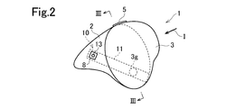
- the airbag apparatus includes an airbag 1 that is normally folded and inflated and deployed in an emergency, and an inflator (not shown) that supplies gas to the airbag 1.
- the airbag apparatus is an airbag apparatus for a passenger seat, and is accommodated in an instrument panel disposed in front of the passenger seat.
- the airbag 1 is inflated and deployed in a space surrounded by an occupant, an instrument panel and a windshield.
- An opening for an inflator is provided on the lower surface of the front portion of the main bag 2 so that gas is supplied from the inflator into the main bag 2.
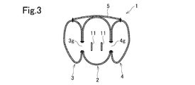
- the tether 5 as a connecting member is disposed from the upper portion of the left sub bag 3 through the upper portion of the main bag 2 to the upper portion of the right sub bag 4.
- the tether 5 is sewn to the upper surface of the left subbag 3 and the right subbag 4 by a suture.
- the first tether 5 is not coupled to the top of the main bag 2.
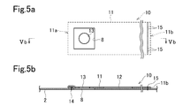
- the valve cross 11 is a strip extending in the front-rear direction.
- the valve cross 11 extends in an oblique direction so as to be lower toward the rear in the inflation completed state of the airbag 1.
- the front end 11 a of the valve cross 11 is sewn to the front side surface of the main bag 2 by a suture thread 14.
- the rear end 11b of the valve cross 11 is a rear portion (facing surface of the occupant) of the main bag 2 and is sewn to an area other than the head and the waist.
- the rear end 11b is sewn by a suture 15 at least below the chest-facing surface, preferably below the surface facing the occupant's waist, in the vicinity of the center in the left-right direction below the occupant-facing surface. ing.
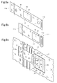
- the valve cross 11 is bellows-folded in the vicinity of the front end 11a.
- the first vent port 13 is present in this bellows-folded portion.
- the bellows-folded portion 11T is sewn to the main bag 2 by a tear seam (not shown) as a temporary fixing member.
- the tear seam is made of a low strength yarn which tears when the main bag 2 expands.
- the tear seam in this embodiment is such that only the upper part and the lower part of the bellows-folded part 11T are sewn to the main bag 2, it is not limited to this.
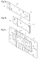
- FIG. 6 c shows a state in which the valve cross 11 is fastened to the main bag 2 in the form of FIG. 6 b.
- the second vent port 12 is disposed at a position overlapping the vent hole 8 of the main bag 2.
- a guide cloth 20 is disposed along the inner surface of the main bag 2 so as to cover the bellows-folded portion 11 T and the subsequent portions of the bridge portions 16 and 17.
- the guide cloth 20 is provided with an opening 25 at a position overlapping the vent hole 8.
- the opening 25 and the vent hole 8 have substantially the same size.
- the upper side, the front side, and the lower side of the guide cloth 20 are sewn to the main bag 2 by sutures 21, 22, 23.
- the rear side of the guide cloth 20 is sewn to the main bag 2 by the suture thread 24 only in the middle in the vertical direction.
- the rear side of the guide cloth 20 is disposed along the rear edge of the vent hole 8 so as to cross the second vent port 12.
- the upper bridge 16 of the valve cross 11 is drawn between the sutures 21, 24 and the lower bridge 17 is pulled between the sutures 23, 24.
- FIGS. 4a, 4b and 6c show the overlap between the valve cross 11 and the main bag 2 at the initial stage of expansion
- FIGS. 5a and 5b show the overlap between the valve cross 11 and the main bag 2 after the expansion is completed.
- FIGS. 4a and 5a are side views in the vicinity of the vent hole 8 of the main bag 2
- FIGS. 4b and 5b show cross sections taken along lines IVb-IVb and Vb-Vb in FIGS. 4a and 5a, respectively.
- the illustration of the guide cloth 20 is omitted in FIGS. 4a-5b.
- the bellows-folded portion 11T of the valve cross 11 maintains the folded state, and the second vent port 12 with the large opening area is the vent hole 8.
- the vent hole 8 has a large opening area. Therefore, the amount of exhaust from the vent hole 8 (the amount of exhaust per unit time) when the airbag 1 contacts the occupant in the out-of-position at the initial stage of expansion is large.
- the main bag 2 expands rearward, that is, in a direction toward the occupant, and the rear end 11b of the valve cross 11 is pulled rearward and obliquely downward.
- the tear seam temporarily fixing the bellows-folded portion 11T is broken, and the bellows-folded portion 11T is pulled back.
- the first vent port 13 with a small opening area overlaps the vent hole 8 as shown in FIGS. 5a and 5b. Therefore, in this state, the vent hole 8 has a small opening area.
- the airbag 1 in the expansion completed state restrains the occupant, the gas in the airbag 1 flows out from the opening 25 and the first vent port 13 through the vent hole 8.
- the storage area of the valve cross 11 may be small.
- valve cross 11 is separated from the communication ports 3g and 4g when the air bag 1 is completely inflated.
- the vent hole opening area is configured so as to be large at the initial stage of inflation of the airbag 1 and smaller at the latter stage of inflation (the state of completion of inflation), but conversely the vent hole opening area at the initial stage of inflation May be reduced or zero (closed state).
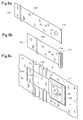
- Figures 7a-7c and Figures 8a-8c illustrate such an arrangement, respectively.
- FIGS. 7a to 7c the first vent port 13 is omitted.
- the suture thread 24 is not provided, and the rear side of the guide cloth 20 is not sewn to the main bag 2.
- FIGS. 7a, 7b and 7c are the same as those of FIGS. 6a, 6b and 6c, and the same reference numerals indicate the same parts.
- the vent holes 8 are closed by the valve cross 11A.
- the first vent port 13 overlaps the vent hole 8.
- the gas in the airbag 1 flows out from the opening 25 and the first vent port 13 through the vent hole 8.
- valve cross 11B is provided with a third vent port 18 with a small opening area.
- the third vent port 18 is located at the center of the vent hole 8 and the opening 25 in the initial state of expansion shown in FIG. 8 b.
- the other configurations of FIGS. 8a, 8b and 8c are the same as those of FIGS. 7a, 7b and 7c, and the same reference numerals indicate the same parts.
- valve cross 13 is in the vertical vertical direction in the expansion completed state, but the upper side of the valve cross 13 may be positioned on the center side of the main bag 2 in the lateral direction than the lower side Alternatively, it may be inclined so as to be located outward in the left-right direction.
- the center of the communication port 3 g is positioned at the center in the vertical width direction of the valve cross 11. That is, although it is located on the center line of the valve cross 11, the center of the communication port 3g may be shifted above or below this center line.
Landscapes
- Engineering & Computer Science (AREA)
- Mechanical Engineering (AREA)
- Air Bags (AREA)
Applications Claiming Priority (2)
| Application Number | Priority Date | Filing Date | Title |
|---|---|---|---|
| JP2017-225917 | 2017-11-24 | ||
| JP2017225917A JP2019093952A (ja) | 2017-11-24 | 2017-11-24 | エアバッグ及びエアバッグ装置 |
Publications (1)
| Publication Number | Publication Date |
|---|---|
| WO2019102780A1 true WO2019102780A1 (ja) | 2019-05-31 |
Family
ID=66631432
Family Applications (1)
| Application Number | Title | Priority Date | Filing Date |
|---|---|---|---|
| PCT/JP2018/039621 Ceased WO2019102780A1 (ja) | 2017-11-24 | 2018-10-25 | エアバッグ及びエアバッグ装置 |
Country Status (2)
| Country | Link |
|---|---|
| JP (1) | JP2019093952A (cg-RX-API-DMAC10.html) |
| WO (1) | WO2019102780A1 (cg-RX-API-DMAC10.html) |
Citations (8)
| Publication number | Priority date | Publication date | Assignee | Title |
|---|---|---|---|---|
| JPH0585295A (ja) * | 1991-03-27 | 1993-04-06 | Nissan Shatai Co Ltd | エアバツグ装置 |
| JPH08324373A (ja) * | 1995-05-30 | 1996-12-10 | Ryosuke Honda | 斜めからの衝撃も緩和する自動車用エアバック |
| US20080079250A1 (en) * | 2006-09-28 | 2008-04-03 | Boyle Walter J | Air Bag Vent |
| JP2009143483A (ja) * | 2007-12-17 | 2009-07-02 | Takata Corp | 助手席用エアバッグ、助手席用エアバッグ装置及び自動車 |
| JP2015536870A (ja) * | 2012-12-13 | 2015-12-24 | タカタ アーゲー | 通気穴の出口断面を制御する装置を含むエアバッグ構成 |
| WO2016002384A1 (ja) * | 2014-06-30 | 2016-01-07 | オートリブ ディベロップメント エービー | エアバッグ装置 |
| JP2016020175A (ja) * | 2014-07-15 | 2016-02-04 | タカタ株式会社 | エアバッグ |
| JP2017094774A (ja) * | 2015-11-18 | 2017-06-01 | トヨタ自動車株式会社 | エアバッグ装置及びエアバッグの製造方法 |
-
2017
- 2017-11-24 JP JP2017225917A patent/JP2019093952A/ja active Pending
-
2018
- 2018-10-25 WO PCT/JP2018/039621 patent/WO2019102780A1/ja not_active Ceased
Patent Citations (8)
| Publication number | Priority date | Publication date | Assignee | Title |
|---|---|---|---|---|
| JPH0585295A (ja) * | 1991-03-27 | 1993-04-06 | Nissan Shatai Co Ltd | エアバツグ装置 |
| JPH08324373A (ja) * | 1995-05-30 | 1996-12-10 | Ryosuke Honda | 斜めからの衝撃も緩和する自動車用エアバック |
| US20080079250A1 (en) * | 2006-09-28 | 2008-04-03 | Boyle Walter J | Air Bag Vent |
| JP2009143483A (ja) * | 2007-12-17 | 2009-07-02 | Takata Corp | 助手席用エアバッグ、助手席用エアバッグ装置及び自動車 |
| JP2015536870A (ja) * | 2012-12-13 | 2015-12-24 | タカタ アーゲー | 通気穴の出口断面を制御する装置を含むエアバッグ構成 |
| WO2016002384A1 (ja) * | 2014-06-30 | 2016-01-07 | オートリブ ディベロップメント エービー | エアバッグ装置 |
| JP2016020175A (ja) * | 2014-07-15 | 2016-02-04 | タカタ株式会社 | エアバッグ |
| JP2017094774A (ja) * | 2015-11-18 | 2017-06-01 | トヨタ自動車株式会社 | エアバッグ装置及びエアバッグの製造方法 |
Also Published As
| Publication number | Publication date |
|---|---|
| JP2019093952A (ja) | 2019-06-20 |
Similar Documents
| Publication | Publication Date | Title |
|---|---|---|
| JP4666059B2 (ja) | 車両用エアバッグ装置 | |
| JP6080344B2 (ja) | エアバッグ装置 | |
| JP6551196B2 (ja) | ファーサイドエアバッグ装置及びエアバッグの折り畳み方法 | |
| CN111819113A (zh) | 安装在车顶上的乘员约束系统 | |
| JP5312087B2 (ja) | サイドエアバッグ装置 | |
| JP2014037159A (ja) | 車両用カーテンエアバッグ装置 | |
| JP2019018791A (ja) | エアバッグ及び乗員拘束装置 | |
| JP4428845B2 (ja) | 自動車のエアバッグ装置 | |
| JP2008081002A (ja) | エアバッグ及びエアバッグ装置 | |
| JP2018058552A (ja) | 車両用カーテンエアバッグ装置 | |
| CN112141038A (zh) | 侧面安全气囊装置和膝部安全气囊装置 | |
| JPWO2016152245A1 (ja) | エアバッグ装置 | |
| JP2018070102A (ja) | 後席用エアバッグ | |
| JP2006142964A (ja) | 頭部保護エアバッグ及び頭部保護エアバッグ装置 | |
| WO2007099668A1 (ja) | エアバッグ及びエアバッグ装置 | |
| WO2021019842A1 (ja) | エアバッグ及びエアバッグ装置 | |
| WO2019225275A1 (ja) | エアバッグ | |
| JP6460070B2 (ja) | 車両用カーテンエアバッグ装置 | |
| JP2019199171A (ja) | エアバッグ装置 | |
| JP2016124497A (ja) | エアバッグ | |
| JP6420157B2 (ja) | エアバッグ | |
| JP6302768B2 (ja) | サイドエアバッグ装置 | |
| JP2007055501A (ja) | 助手席用エアバッグ装置 | |
| JP2018114838A (ja) | エアバッグ | |
| JP7322551B2 (ja) | エアバッグ、エアバッグ装置及び車両用シート |
Legal Events
| Date | Code | Title | Description |
|---|---|---|---|
| 121 | Ep: the epo has been informed by wipo that ep was designated in this application |
Ref document number: 18880398 Country of ref document: EP Kind code of ref document: A1 |
|
| NENP | Non-entry into the national phase |
Ref country code: DE |
|
| 122 | Ep: pct application non-entry in european phase |
Ref document number: 18880398 Country of ref document: EP Kind code of ref document: A1 |