WO2019098130A1 - 被覆切削工具ならびにその製造方法および化学蒸着装置 - Google Patents
被覆切削工具ならびにその製造方法および化学蒸着装置 Download PDFInfo
- Publication number
- WO2019098130A1 WO2019098130A1 PCT/JP2018/041620 JP2018041620W WO2019098130A1 WO 2019098130 A1 WO2019098130 A1 WO 2019098130A1 JP 2018041620 W JP2018041620 W JP 2018041620W WO 2019098130 A1 WO2019098130 A1 WO 2019098130A1
- Authority
- WO
- WIPO (PCT)
- Prior art keywords
- gas
- mixed gas
- cutting tool
- coated cutting
- ray diffraction
- Prior art date
Links
Images


Classifications
-
- B—PERFORMING OPERATIONS; TRANSPORTING
- B23—MACHINE TOOLS; METAL-WORKING NOT OTHERWISE PROVIDED FOR
- B23B—TURNING; BORING
- B23B27/00—Tools for turning or boring machines; Tools of a similar kind in general; Accessories therefor
- B23B27/14—Cutting tools of which the bits or tips or cutting inserts are of special material
- B23B27/148—Composition of the cutting inserts
-
- B—PERFORMING OPERATIONS; TRANSPORTING
- B23—MACHINE TOOLS; METAL-WORKING NOT OTHERWISE PROVIDED FOR
- B23C—MILLING
- B23C5/00—Milling-cutters
- B23C5/16—Milling-cutters characterised by physical features other than shape
-
- C—CHEMISTRY; METALLURGY
- C21—METALLURGY OF IRON
- C21D—MODIFYING THE PHYSICAL STRUCTURE OF FERROUS METALS; GENERAL DEVICES FOR HEAT TREATMENT OF FERROUS OR NON-FERROUS METALS OR ALLOYS; MAKING METAL MALLEABLE, e.g. BY DECARBURISATION OR TEMPERING
- C21D9/00—Heat treatment, e.g. annealing, hardening, quenching or tempering, adapted for particular articles; Furnaces therefor
- C21D9/22—Heat treatment, e.g. annealing, hardening, quenching or tempering, adapted for particular articles; Furnaces therefor for drills; for milling cutters; for machine cutting tools
-
- C—CHEMISTRY; METALLURGY
- C22—METALLURGY; FERROUS OR NON-FERROUS ALLOYS; TREATMENT OF ALLOYS OR NON-FERROUS METALS
- C22C—ALLOYS
- C22C21/00—Alloys based on aluminium
-
- C—CHEMISTRY; METALLURGY
- C22—METALLURGY; FERROUS OR NON-FERROUS ALLOYS; TREATMENT OF ALLOYS OR NON-FERROUS METALS
- C22F—CHANGING THE PHYSICAL STRUCTURE OF NON-FERROUS METALS AND NON-FERROUS ALLOYS
- C22F1/00—Changing the physical structure of non-ferrous metals or alloys by heat treatment or by hot or cold working
- C22F1/04—Changing the physical structure of non-ferrous metals or alloys by heat treatment or by hot or cold working of aluminium or alloys based thereon
-
- C—CHEMISTRY; METALLURGY
- C23—COATING METALLIC MATERIAL; COATING MATERIAL WITH METALLIC MATERIAL; CHEMICAL SURFACE TREATMENT; DIFFUSION TREATMENT OF METALLIC MATERIAL; COATING BY VACUUM EVAPORATION, BY SPUTTERING, BY ION IMPLANTATION OR BY CHEMICAL VAPOUR DEPOSITION, IN GENERAL; INHIBITING CORROSION OF METALLIC MATERIAL OR INCRUSTATION IN GENERAL
- C23C—COATING METALLIC MATERIAL; COATING MATERIAL WITH METALLIC MATERIAL; SURFACE TREATMENT OF METALLIC MATERIAL BY DIFFUSION INTO THE SURFACE, BY CHEMICAL CONVERSION OR SUBSTITUTION; COATING BY VACUUM EVAPORATION, BY SPUTTERING, BY ION IMPLANTATION OR BY CHEMICAL VAPOUR DEPOSITION, IN GENERAL
- C23C16/00—Chemical coating by decomposition of gaseous compounds, without leaving reaction products of surface material in the coating, i.e. chemical vapour deposition [CVD] processes
- C23C16/02—Pretreatment of the material to be coated
- C23C16/0272—Deposition of sub-layers, e.g. to promote the adhesion of the main coating
-
- C—CHEMISTRY; METALLURGY
- C23—COATING METALLIC MATERIAL; COATING MATERIAL WITH METALLIC MATERIAL; CHEMICAL SURFACE TREATMENT; DIFFUSION TREATMENT OF METALLIC MATERIAL; COATING BY VACUUM EVAPORATION, BY SPUTTERING, BY ION IMPLANTATION OR BY CHEMICAL VAPOUR DEPOSITION, IN GENERAL; INHIBITING CORROSION OF METALLIC MATERIAL OR INCRUSTATION IN GENERAL
- C23C—COATING METALLIC MATERIAL; COATING MATERIAL WITH METALLIC MATERIAL; SURFACE TREATMENT OF METALLIC MATERIAL BY DIFFUSION INTO THE SURFACE, BY CHEMICAL CONVERSION OR SUBSTITUTION; COATING BY VACUUM EVAPORATION, BY SPUTTERING, BY ION IMPLANTATION OR BY CHEMICAL VAPOUR DEPOSITION, IN GENERAL
- C23C16/00—Chemical coating by decomposition of gaseous compounds, without leaving reaction products of surface material in the coating, i.e. chemical vapour deposition [CVD] processes
- C23C16/22—Chemical coating by decomposition of gaseous compounds, without leaving reaction products of surface material in the coating, i.e. chemical vapour deposition [CVD] processes characterised by the deposition of inorganic material, other than metallic material
- C23C16/30—Deposition of compounds, mixtures or solid solutions, e.g. borides, carbides, nitrides
- C23C16/34—Nitrides
-
- C—CHEMISTRY; METALLURGY
- C23—COATING METALLIC MATERIAL; COATING MATERIAL WITH METALLIC MATERIAL; CHEMICAL SURFACE TREATMENT; DIFFUSION TREATMENT OF METALLIC MATERIAL; COATING BY VACUUM EVAPORATION, BY SPUTTERING, BY ION IMPLANTATION OR BY CHEMICAL VAPOUR DEPOSITION, IN GENERAL; INHIBITING CORROSION OF METALLIC MATERIAL OR INCRUSTATION IN GENERAL
- C23C—COATING METALLIC MATERIAL; COATING MATERIAL WITH METALLIC MATERIAL; SURFACE TREATMENT OF METALLIC MATERIAL BY DIFFUSION INTO THE SURFACE, BY CHEMICAL CONVERSION OR SUBSTITUTION; COATING BY VACUUM EVAPORATION, BY SPUTTERING, BY ION IMPLANTATION OR BY CHEMICAL VAPOUR DEPOSITION, IN GENERAL
- C23C16/00—Chemical coating by decomposition of gaseous compounds, without leaving reaction products of surface material in the coating, i.e. chemical vapour deposition [CVD] processes
- C23C16/44—Chemical coating by decomposition of gaseous compounds, without leaving reaction products of surface material in the coating, i.e. chemical vapour deposition [CVD] processes characterised by the method of coating
- C23C16/448—Chemical coating by decomposition of gaseous compounds, without leaving reaction products of surface material in the coating, i.e. chemical vapour deposition [CVD] processes characterised by the method of coating characterised by the method used for generating reactive gas streams, e.g. by evaporation or sublimation of precursor materials
- C23C16/4488—Chemical coating by decomposition of gaseous compounds, without leaving reaction products of surface material in the coating, i.e. chemical vapour deposition [CVD] processes characterised by the method of coating characterised by the method used for generating reactive gas streams, e.g. by evaporation or sublimation of precursor materials by in situ generation of reactive gas by chemical or electrochemical reaction
-
- C—CHEMISTRY; METALLURGY
- C23—COATING METALLIC MATERIAL; COATING MATERIAL WITH METALLIC MATERIAL; CHEMICAL SURFACE TREATMENT; DIFFUSION TREATMENT OF METALLIC MATERIAL; COATING BY VACUUM EVAPORATION, BY SPUTTERING, BY ION IMPLANTATION OR BY CHEMICAL VAPOUR DEPOSITION, IN GENERAL; INHIBITING CORROSION OF METALLIC MATERIAL OR INCRUSTATION IN GENERAL
- C23C—COATING METALLIC MATERIAL; COATING MATERIAL WITH METALLIC MATERIAL; SURFACE TREATMENT OF METALLIC MATERIAL BY DIFFUSION INTO THE SURFACE, BY CHEMICAL CONVERSION OR SUBSTITUTION; COATING BY VACUUM EVAPORATION, BY SPUTTERING, BY ION IMPLANTATION OR BY CHEMICAL VAPOUR DEPOSITION, IN GENERAL
- C23C16/00—Chemical coating by decomposition of gaseous compounds, without leaving reaction products of surface material in the coating, i.e. chemical vapour deposition [CVD] processes
- C23C16/44—Chemical coating by decomposition of gaseous compounds, without leaving reaction products of surface material in the coating, i.e. chemical vapour deposition [CVD] processes characterised by the method of coating
- C23C16/455—Chemical coating by decomposition of gaseous compounds, without leaving reaction products of surface material in the coating, i.e. chemical vapour deposition [CVD] processes characterised by the method of coating characterised by the method used for introducing gases into reaction chamber or for modifying gas flows in reaction chamber
- C23C16/45502—Flow conditions in reaction chamber
- C23C16/45508—Radial flow
-
- C—CHEMISTRY; METALLURGY
- C23—COATING METALLIC MATERIAL; COATING MATERIAL WITH METALLIC MATERIAL; CHEMICAL SURFACE TREATMENT; DIFFUSION TREATMENT OF METALLIC MATERIAL; COATING BY VACUUM EVAPORATION, BY SPUTTERING, BY ION IMPLANTATION OR BY CHEMICAL VAPOUR DEPOSITION, IN GENERAL; INHIBITING CORROSION OF METALLIC MATERIAL OR INCRUSTATION IN GENERAL
- C23C—COATING METALLIC MATERIAL; COATING MATERIAL WITH METALLIC MATERIAL; SURFACE TREATMENT OF METALLIC MATERIAL BY DIFFUSION INTO THE SURFACE, BY CHEMICAL CONVERSION OR SUBSTITUTION; COATING BY VACUUM EVAPORATION, BY SPUTTERING, BY ION IMPLANTATION OR BY CHEMICAL VAPOUR DEPOSITION, IN GENERAL
- C23C16/00—Chemical coating by decomposition of gaseous compounds, without leaving reaction products of surface material in the coating, i.e. chemical vapour deposition [CVD] processes
- C23C16/44—Chemical coating by decomposition of gaseous compounds, without leaving reaction products of surface material in the coating, i.e. chemical vapour deposition [CVD] processes characterised by the method of coating
- C23C16/455—Chemical coating by decomposition of gaseous compounds, without leaving reaction products of surface material in the coating, i.e. chemical vapour deposition [CVD] processes characterised by the method of coating characterised by the method used for introducing gases into reaction chamber or for modifying gas flows in reaction chamber
- C23C16/45512—Premixing before introduction in the reaction chamber
-
- C—CHEMISTRY; METALLURGY
- C23—COATING METALLIC MATERIAL; COATING MATERIAL WITH METALLIC MATERIAL; CHEMICAL SURFACE TREATMENT; DIFFUSION TREATMENT OF METALLIC MATERIAL; COATING BY VACUUM EVAPORATION, BY SPUTTERING, BY ION IMPLANTATION OR BY CHEMICAL VAPOUR DEPOSITION, IN GENERAL; INHIBITING CORROSION OF METALLIC MATERIAL OR INCRUSTATION IN GENERAL
- C23C—COATING METALLIC MATERIAL; COATING MATERIAL WITH METALLIC MATERIAL; SURFACE TREATMENT OF METALLIC MATERIAL BY DIFFUSION INTO THE SURFACE, BY CHEMICAL CONVERSION OR SUBSTITUTION; COATING BY VACUUM EVAPORATION, BY SPUTTERING, BY ION IMPLANTATION OR BY CHEMICAL VAPOUR DEPOSITION, IN GENERAL
- C23C16/00—Chemical coating by decomposition of gaseous compounds, without leaving reaction products of surface material in the coating, i.e. chemical vapour deposition [CVD] processes
- C23C16/44—Chemical coating by decomposition of gaseous compounds, without leaving reaction products of surface material in the coating, i.e. chemical vapour deposition [CVD] processes characterised by the method of coating
- C23C16/455—Chemical coating by decomposition of gaseous compounds, without leaving reaction products of surface material in the coating, i.e. chemical vapour deposition [CVD] processes characterised by the method of coating characterised by the method used for introducing gases into reaction chamber or for modifying gas flows in reaction chamber
- C23C16/45561—Gas plumbing upstream of the reaction chamber
-
- C—CHEMISTRY; METALLURGY
- C23—COATING METALLIC MATERIAL; COATING MATERIAL WITH METALLIC MATERIAL; CHEMICAL SURFACE TREATMENT; DIFFUSION TREATMENT OF METALLIC MATERIAL; COATING BY VACUUM EVAPORATION, BY SPUTTERING, BY ION IMPLANTATION OR BY CHEMICAL VAPOUR DEPOSITION, IN GENERAL; INHIBITING CORROSION OF METALLIC MATERIAL OR INCRUSTATION IN GENERAL
- C23C—COATING METALLIC MATERIAL; COATING MATERIAL WITH METALLIC MATERIAL; SURFACE TREATMENT OF METALLIC MATERIAL BY DIFFUSION INTO THE SURFACE, BY CHEMICAL CONVERSION OR SUBSTITUTION; COATING BY VACUUM EVAPORATION, BY SPUTTERING, BY ION IMPLANTATION OR BY CHEMICAL VAPOUR DEPOSITION, IN GENERAL
- C23C16/00—Chemical coating by decomposition of gaseous compounds, without leaving reaction products of surface material in the coating, i.e. chemical vapour deposition [CVD] processes
- C23C16/44—Chemical coating by decomposition of gaseous compounds, without leaving reaction products of surface material in the coating, i.e. chemical vapour deposition [CVD] processes characterised by the method of coating
- C23C16/455—Chemical coating by decomposition of gaseous compounds, without leaving reaction products of surface material in the coating, i.e. chemical vapour deposition [CVD] processes characterised by the method of coating characterised by the method used for introducing gases into reaction chamber or for modifying gas flows in reaction chamber
- C23C16/45563—Gas nozzles
- C23C16/45574—Nozzles for more than one gas
-
- C—CHEMISTRY; METALLURGY
- C23—COATING METALLIC MATERIAL; COATING MATERIAL WITH METALLIC MATERIAL; CHEMICAL SURFACE TREATMENT; DIFFUSION TREATMENT OF METALLIC MATERIAL; COATING BY VACUUM EVAPORATION, BY SPUTTERING, BY ION IMPLANTATION OR BY CHEMICAL VAPOUR DEPOSITION, IN GENERAL; INHIBITING CORROSION OF METALLIC MATERIAL OR INCRUSTATION IN GENERAL
- C23C—COATING METALLIC MATERIAL; COATING MATERIAL WITH METALLIC MATERIAL; SURFACE TREATMENT OF METALLIC MATERIAL BY DIFFUSION INTO THE SURFACE, BY CHEMICAL CONVERSION OR SUBSTITUTION; COATING BY VACUUM EVAPORATION, BY SPUTTERING, BY ION IMPLANTATION OR BY CHEMICAL VAPOUR DEPOSITION, IN GENERAL
- C23C16/00—Chemical coating by decomposition of gaseous compounds, without leaving reaction products of surface material in the coating, i.e. chemical vapour deposition [CVD] processes
- C23C16/44—Chemical coating by decomposition of gaseous compounds, without leaving reaction products of surface material in the coating, i.e. chemical vapour deposition [CVD] processes characterised by the method of coating
- C23C16/455—Chemical coating by decomposition of gaseous compounds, without leaving reaction products of surface material in the coating, i.e. chemical vapour deposition [CVD] processes characterised by the method of coating characterised by the method used for introducing gases into reaction chamber or for modifying gas flows in reaction chamber
- C23C16/45563—Gas nozzles
- C23C16/45576—Coaxial inlets for each gas
-
- C—CHEMISTRY; METALLURGY
- C23—COATING METALLIC MATERIAL; COATING MATERIAL WITH METALLIC MATERIAL; CHEMICAL SURFACE TREATMENT; DIFFUSION TREATMENT OF METALLIC MATERIAL; COATING BY VACUUM EVAPORATION, BY SPUTTERING, BY ION IMPLANTATION OR BY CHEMICAL VAPOUR DEPOSITION, IN GENERAL; INHIBITING CORROSION OF METALLIC MATERIAL OR INCRUSTATION IN GENERAL
- C23C—COATING METALLIC MATERIAL; COATING MATERIAL WITH METALLIC MATERIAL; SURFACE TREATMENT OF METALLIC MATERIAL BY DIFFUSION INTO THE SURFACE, BY CHEMICAL CONVERSION OR SUBSTITUTION; COATING BY VACUUM EVAPORATION, BY SPUTTERING, BY ION IMPLANTATION OR BY CHEMICAL VAPOUR DEPOSITION, IN GENERAL
- C23C16/00—Chemical coating by decomposition of gaseous compounds, without leaving reaction products of surface material in the coating, i.e. chemical vapour deposition [CVD] processes
- C23C16/44—Chemical coating by decomposition of gaseous compounds, without leaving reaction products of surface material in the coating, i.e. chemical vapour deposition [CVD] processes characterised by the method of coating
- C23C16/455—Chemical coating by decomposition of gaseous compounds, without leaving reaction products of surface material in the coating, i.e. chemical vapour deposition [CVD] processes characterised by the method of coating characterised by the method used for introducing gases into reaction chamber or for modifying gas flows in reaction chamber
- C23C16/45563—Gas nozzles
- C23C16/45578—Elongated nozzles, tubes with holes
-
- C—CHEMISTRY; METALLURGY
- C23—COATING METALLIC MATERIAL; COATING MATERIAL WITH METALLIC MATERIAL; CHEMICAL SURFACE TREATMENT; DIFFUSION TREATMENT OF METALLIC MATERIAL; COATING BY VACUUM EVAPORATION, BY SPUTTERING, BY ION IMPLANTATION OR BY CHEMICAL VAPOUR DEPOSITION, IN GENERAL; INHIBITING CORROSION OF METALLIC MATERIAL OR INCRUSTATION IN GENERAL
- C23C—COATING METALLIC MATERIAL; COATING MATERIAL WITH METALLIC MATERIAL; SURFACE TREATMENT OF METALLIC MATERIAL BY DIFFUSION INTO THE SURFACE, BY CHEMICAL CONVERSION OR SUBSTITUTION; COATING BY VACUUM EVAPORATION, BY SPUTTERING, BY ION IMPLANTATION OR BY CHEMICAL VAPOUR DEPOSITION, IN GENERAL
- C23C16/00—Chemical coating by decomposition of gaseous compounds, without leaving reaction products of surface material in the coating, i.e. chemical vapour deposition [CVD] processes
- C23C16/56—After-treatment
-
- C—CHEMISTRY; METALLURGY
- C23—COATING METALLIC MATERIAL; COATING MATERIAL WITH METALLIC MATERIAL; CHEMICAL SURFACE TREATMENT; DIFFUSION TREATMENT OF METALLIC MATERIAL; COATING BY VACUUM EVAPORATION, BY SPUTTERING, BY ION IMPLANTATION OR BY CHEMICAL VAPOUR DEPOSITION, IN GENERAL; INHIBITING CORROSION OF METALLIC MATERIAL OR INCRUSTATION IN GENERAL
- C23C—COATING METALLIC MATERIAL; COATING MATERIAL WITH METALLIC MATERIAL; SURFACE TREATMENT OF METALLIC MATERIAL BY DIFFUSION INTO THE SURFACE, BY CHEMICAL CONVERSION OR SUBSTITUTION; COATING BY VACUUM EVAPORATION, BY SPUTTERING, BY ION IMPLANTATION OR BY CHEMICAL VAPOUR DEPOSITION, IN GENERAL
- C23C28/00—Coating for obtaining at least two superposed coatings either by methods not provided for in a single one of groups C23C2/00 - C23C26/00 or by combinations of methods provided for in subclasses C23C and C25C or C25D
- C23C28/04—Coating for obtaining at least two superposed coatings either by methods not provided for in a single one of groups C23C2/00 - C23C26/00 or by combinations of methods provided for in subclasses C23C and C25C or C25D only coatings of inorganic non-metallic material
- C23C28/042—Coating for obtaining at least two superposed coatings either by methods not provided for in a single one of groups C23C2/00 - C23C26/00 or by combinations of methods provided for in subclasses C23C and C25C or C25D only coatings of inorganic non-metallic material including a refractory ceramic layer, e.g. refractory metal oxides, ZrO2, rare earth oxides
-
- C—CHEMISTRY; METALLURGY
- C23—COATING METALLIC MATERIAL; COATING MATERIAL WITH METALLIC MATERIAL; CHEMICAL SURFACE TREATMENT; DIFFUSION TREATMENT OF METALLIC MATERIAL; COATING BY VACUUM EVAPORATION, BY SPUTTERING, BY ION IMPLANTATION OR BY CHEMICAL VAPOUR DEPOSITION, IN GENERAL; INHIBITING CORROSION OF METALLIC MATERIAL OR INCRUSTATION IN GENERAL
- C23C—COATING METALLIC MATERIAL; COATING MATERIAL WITH METALLIC MATERIAL; SURFACE TREATMENT OF METALLIC MATERIAL BY DIFFUSION INTO THE SURFACE, BY CHEMICAL CONVERSION OR SUBSTITUTION; COATING BY VACUUM EVAPORATION, BY SPUTTERING, BY ION IMPLANTATION OR BY CHEMICAL VAPOUR DEPOSITION, IN GENERAL
- C23C28/00—Coating for obtaining at least two superposed coatings either by methods not provided for in a single one of groups C23C2/00 - C23C26/00 or by combinations of methods provided for in subclasses C23C and C25C or C25D
- C23C28/04—Coating for obtaining at least two superposed coatings either by methods not provided for in a single one of groups C23C2/00 - C23C26/00 or by combinations of methods provided for in subclasses C23C and C25C or C25D only coatings of inorganic non-metallic material
- C23C28/044—Coating for obtaining at least two superposed coatings either by methods not provided for in a single one of groups C23C2/00 - C23C26/00 or by combinations of methods provided for in subclasses C23C and C25C or C25D only coatings of inorganic non-metallic material coatings specially adapted for cutting tools or wear applications
-
- C—CHEMISTRY; METALLURGY
- C23—COATING METALLIC MATERIAL; COATING MATERIAL WITH METALLIC MATERIAL; CHEMICAL SURFACE TREATMENT; DIFFUSION TREATMENT OF METALLIC MATERIAL; COATING BY VACUUM EVAPORATION, BY SPUTTERING, BY ION IMPLANTATION OR BY CHEMICAL VAPOUR DEPOSITION, IN GENERAL; INHIBITING CORROSION OF METALLIC MATERIAL OR INCRUSTATION IN GENERAL
- C23C—COATING METALLIC MATERIAL; COATING MATERIAL WITH METALLIC MATERIAL; SURFACE TREATMENT OF METALLIC MATERIAL BY DIFFUSION INTO THE SURFACE, BY CHEMICAL CONVERSION OR SUBSTITUTION; COATING BY VACUUM EVAPORATION, BY SPUTTERING, BY ION IMPLANTATION OR BY CHEMICAL VAPOUR DEPOSITION, IN GENERAL
- C23C30/00—Coating with metallic material characterised only by the composition of the metallic material, i.e. not characterised by the coating process
- C23C30/005—Coating with metallic material characterised only by the composition of the metallic material, i.e. not characterised by the coating process on hard metal substrates
-
- B—PERFORMING OPERATIONS; TRANSPORTING
- B23—MACHINE TOOLS; METAL-WORKING NOT OTHERWISE PROVIDED FOR
- B23B—TURNING; BORING
- B23B2228/00—Properties of materials of tools or workpieces, materials of tools or workpieces applied in a specific manner
- B23B2228/10—Coatings
Definitions
- the present invention relates to a coated cutting tool having a hard film containing a nitride containing Al and Cr coated by a chemical vapor deposition method on the surface of the tool, a method of manufacturing the same, and a chemical vapor deposition apparatus.
- a coated cutting tool in which a hard coating is coated on the surface of the tool by a physical vapor deposition method or a chemical vapor deposition method is used.
- hard coatings composed of nitrides of Al and Ti and hard coatings composed of nitrides of Al and Cr are film types excellent in wear resistance and heat resistance and widely used for coated cutting tools .
- Patent Document 1 gas group A consisting of NH 3 , N 2 and H 2 , CrCl 3 , AlCl 3 , Al (CH 3) It is disclosed that a hard film consisting of nitride of Al and Cr consisting of cubic crystal structure is coated on the surface of a tool base by separately supplying a gas group B consisting of 3 , N 2 and H 2 separately. .
- Patent Document 1 discloses that when a hard coating made of nitride of Al and Cr is coated by a chemical vapor deposition method, NH 3 gas which is an alkali gas and CrCl 4 which is a halogen gas. (3) Excessive reaction of the gas or AlCl 3 gas may make it difficult to stabilize the film formation, and furthermore, since there is no specific surface orientation, the durability as a coated cutting tool may not be sufficient. It was confirmed. Therefore, an object of the present invention is to obtain a coated cutting tool coated with a nitride containing Al and Cr, which has excellent durability, and a manufacturing method and a chemical vapor deposition apparatus for coating the nitride.
- the hard coating is a nitride containing at least 60 atomic% of Al, at least 10 atomic% of Cr, and a total content ratio of Al and Cr of at least 90 atomic%, based on the total amount of metal elements including metalloids.
- the peak intensity attributable to the fcc structure in X-ray diffraction shows the maximum intensity
- a collection of columnar particles grown in the film thickness direction with respect to the surface of the substrate
- the hard coating has an X-ray diffraction intensity ratio TC (311) of 1.30 or more.
- the cutting tool which concerns on the said embodiment satisfies one or more of each following matter.
- the X-ray diffraction intensity ratio TC (311) is 2.00 or more.
- the X-ray diffraction intensity ratio TC (311) is the X-ray diffraction intensity ratio TC (hkl) (however, the (hkl) plane is (111) plane, (200) plane, (220) plane, (311) B) greater than (222), (400), (331) and (420)).
- the values of the X-ray diffraction intensity ratios TC (420) and TC (200) are less than 1.00.
- the value of TB / TA is 0.050 or more where the hard coating has a total peak intensity of the fcc structure in X-ray diffraction as TA and a peak intensity due to the (422) plane as TB.
- the average width on the surface side of the columnar particles is 0.1 ⁇ m or more and 2.0 ⁇ m or less.
- the hard film has, in a microstructure using a transmission electron microscope, a portion of a single layer structure having a relatively high content ratio of Al and a portion having a laminated structure having a relatively low content ratio of Al. Having dispersed crystal particles. (7) Having an intermediate film between the substrate and the hard film. (8) Having an upper layer on the hard film.
- a method of producing a coated cutting tool comprising: applying a hard coating comprising an Al- and Cr-containing nitride onto a surface of a substrate by a chemical vapor deposition method according to an embodiment Heating the temperature in the furnace containing the base material to 750 ° C. or more and 850 ° C.
- a chemical vapor deposition apparatus including a gas preheating unit and a furnace gas releasing unit for introducing a gas into a reaction container according to an embodiment of the present invention
- the gas preheating unit is (1) A Cr chloride gas generation unit for generating a mixed gas a1 containing Cr chloride gas by bringing a mixed gas for generating Cr chloride gas into contact with metal Cr, (2) a first preheating unit for preheating the mixed gas a2, (3) a second preheating unit for preheating the mixed gas B, and (4) A mixing unit that mixes the mixed gas a1 with the mixed gas a2 to form a mixed gas A.
- the gas discharge unit has a first pipe provided with a nozzle hole for introducing the mixed gas A into the reaction vessel, and a second pipe provided with a nozzle hole for introducing the mixed gas B into the reaction vessel, The first pipe is provided concentrically on the outside of the second pipe.
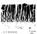
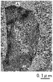
- FIG. 1A It is a drawing substitute photograph (magnification of 10,000 times) of the scanning electron microscope (SEM) image which shows the cross section of the rake surface of the coated cutting tool of Example 1.
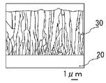
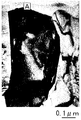
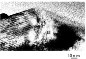
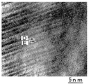
- FIG. 1A It is a schematic model line with respect to the drawing substitute photograph of FIG. 1A. It is a drawing substitute photograph which binarized the drawing substitute photograph of FIG. 1A. It is a drawing substitute photograph (magnification 200,000 times) of the image of the transmission electron microscope (TEM) of the hard film of Example 1.
- TEM transmission electron microscope
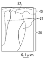
- FIG. 2A It is a schematic model line with respect to the drawing substitute photograph of FIG. 2A. It is a drawing substitute photograph which binarized the drawing substitute photograph of FIG. 2A. It is a drawing substitute photograph (magnification 2,000,000 times) of the TEM image which expanded the A section of FIG.
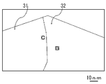
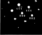
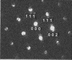
- FIG. 3A It is a schematic diagram line with respect to the drawing substitute photograph of FIG. 3A. It is a drawing substitute photograph which binarized the drawing substitute photograph of FIG. 3A. It is a drawing substitute photograph which shows the nanobeam diffraction pattern in B part of the drawing substitute photograph of FIG. 3A. It is a drawing substitute photograph which binarized the drawing substitute photograph of FIG. 4A. It is a drawing substitute photograph (magnification 4,000,000 times) of the TEM image which expanded the C section of the drawing substitute photograph of FIG. 3A. It is a schematic model line with respect to the drawing substitute photograph of FIG. 5A. It is a drawing substitute photograph which binarized the drawing substitute photograph of FIG. 5A.
- FIG. 2 is a view showing the X-ray diffraction measurement results of Example 1; It is a schematic diagram of the chemical vapor deposition apparatus (CVD furnace) used for coating of the hard film of an example.
- CVD furnace chemical vapor deposition apparatus
- FIG. 5 is a schematic view of a chemical vapor deposition apparatus (CVD furnace) used for coating the hard film of Comparative Example 2; It is a schematic sectional drawing of the gas jet nozzle of the chemical vapor deposition apparatus (CVD furnace) used for coating of the hard film of the comparative example 2.
- FIG. It is a schematic diagram of the chemical vapor deposition apparatus (CVD furnace) used for coating of the hard film of Comparative Examples 3 and 4. It is a schematic sectional drawing of the gas jet nozzle of the chemical vapor deposition apparatus (CVD furnace) used for coating of the hard film of Comparative Examples 3 and 4.
- the inventors have found that, for nitrides mainly composed of Al and Cr, by controlling the orientation of the (311) plane, the durability is improved when used as a coating film of a coated cutting tool,
- the present invention has been reached. That is, for nitrides mainly composed of Al and Cr, the X-ray diffraction intensity of each crystal plane is determined, and the X-ray diffraction intensity of the (311) plane is arranged by paying attention to the X-ray diffraction intensity of the (311) plane. It has been surprisingly found that the durability of the coated cutting tool is improved when there is a fixed relationship to the diffraction intensity of the other surface.
- the NH 3 gas is an alkaline gas, in order not to overreact and CrCl 3 gas and AlCl 3 gas is a halogen gas, the total amount of the NH 3 gas of N 2 gas and H 2 gas in the mixed gas It has also been found that it is necessary to make the ratio to be specific, and that the Cr chloride gas needs to be generated in a CVD furnace.
- composition of a hard film which constitutes a coated cutting tool of one embodiment of the present invention the composition, the crystal structure, the characteristic, and the details of the manufacturing method and the manufacturing apparatus are explained.
- the hard film according to the present embodiment is a nitride based on Al and Cr.
- the film containing nitride of Al and Cr is a film excellent in wear resistance and heat resistance.
- the hard film according to the present embodiment has an Al content of 60 atomic% with respect to the total amount of metal elements including metalloids (hereinafter referred to as metal elements). And above. Furthermore, it is preferable to make the content ratio of Al 70 atomic% or more. However, when the content ratio of Al is too high, AlN of a fragile hcp (hexagon close-packed) structure is increased, and the durability of the coated cutting tool is reduced. Therefore, the content ratio of Al is preferably 90 atomic% or less.
- the content ratio of Cr is 10 atomic% or more. Furthermore, the content ratio of Cr is preferably 15 atomic% or more. However, if the content ratio of Cr is too high, the content ratio of Al relatively decreases and the heat resistance decreases. Therefore, the content ratio of Cr is preferably 30 atomic% or less.
- the total content ratio of Al and Cr is set to 90 atomic% or more in order to impart high heat resistance to the hard coating. Furthermore, the total content ratio of Al and Cr is preferably 95 atomic% or more.
- the hard film according to the present embodiment may contain metal elements other than Al and Cr. For example, Ti, Si, Zr, B, and V may be contained. These elements are elements generally added to AlTi-based nitrides and AlCr-based nitrides, and a small amount of addition does not significantly reduce the durability of the coated cutting tool.
- the hard film according to the present embodiment may be a nitride of Al and Cr.
- the hard film according to the present embodiment may contain 1 mass% or less of the components contained in the film forming gas such as oxygen, carbon and chlorine as unavoidable impurities, when the entire hard film is 100% by mass. If the hard film according to the present embodiment is a nitride as a whole, it may partially contain oxides, composite carbides and composite carbonitrides based on Al and Cr, and the like due to these impurities. .
- ⁇ Crystal structure> In the hard coating according to the present embodiment, one of X-ray peak intensities (peak intensities) attributed to the fcc (face-centered cubic lattice) structure in X-ray diffraction shows the maximum intensity, and the fcc structure is the main.
- the hard film based on the hcp structure and the hard film of amorphous are low in hardness and weak, and the durability of the coated cutting tool is significantly reduced.
- the peak strength attributable to the fcc structure shows the maximum strength, the hardness and the toughness of the hard film are increased, and the durability of the coated cutting tool is improved.
- the hard film according to the present embodiment preferably has a single structure of fcc structure, but if any of the peak intensities resulting from the fcc structure show the maximum strength, it partially contains the hcp structure It is also good.
- the hard coating may not have a high hardness, and may have an hcp structure.
- the content ratio of the hcp structure is too high, the durability of the coated cutting tool is reduced. Therefore, even when the hcp structure is contained, it is preferable to set the maximum peak intensity caused by the hcp structure to 1/10 or less of the maximum peak intensity caused by the fcc structure.
- the hard film according to the present embodiment has (111) surface, (200) surface, (220) surface, (311) surface, (222) surface, (400) surface, (331) of fcc structure in X-ray diffraction. It has peak intensity in at least 9 planes of planes, (420) plane and (422) plane. The inventors have found that fine columnar particles increase as the X-ray diffraction intensity ratio attributed to the (311) plane increases.
- the X-ray diffraction intensity ratio TC (311) described below is set to 1.30 or more for the X-ray diffraction intensity ratio attributed to the (311) plane. Then, the X-ray diffraction intensity ratio TC (311) attributed to the (311) plane is the above-mentioned other plane (the standard X-ray diffraction intensity of aluminum nitride has no (422) plane, so Further, by increasing the X-ray diffraction intensity ratio of the eight surfaces excluding the above, the film structure becomes finer, the plastic deformation of the hard film is suppressed, and the film wear is easily suppressed, which is also preferable. I found out.
- the X-ray diffraction intensity ratio TC (hkl) represented by the following equation (Equation 1) is determined for the X-ray diffraction intensity ratio TC (hkl) of each plane including the (311) plane.
- the intensity ratio TC (311) is evaluated.
- TC (hk1) ⁇ I (hk1) / IO (hk1) ⁇ / [[ ⁇ I (hk1) / IO (hk1) ⁇ / 8]
- I o (hkl) Standard X-ray diffraction intensity of (hkl) plane of aluminum nitride described in ICDD (International Center for Dffraction Data) file number 00-025- 1495.
- ⁇ means the sum of the following eight planes.
- (Hkl) (111) plane, (200) plane, (220) plane, (311) plane, (222) plane, (400) plane, (331) plane and (420) plane.
- the aluminum nitride standard X-ray diffraction intensity similar to the X-ray diffraction of aluminum chromium nitride is used.
- the fcc structure aluminum nitride has the (420) plane: It can be confirmed that the X-ray diffraction intensity of is high. Further, since the standard X-ray diffraction intensity of the aluminum nitride does not have the (422) plane, the X diffraction intensity ratio TC (hkl) is obtained from the above-described eight planes.
- the durability of the coated cutting tool can be improved by using nitrides mainly composed of Al and Cr in which the value of the X-ray diffraction intensity ratio TC (311) is 1.30 or more. It can be enhanced. Further, the X-ray diffraction intensity ratio TC (311) is more preferably 1.80 or more. More preferably, the X-ray diffraction intensity ratio TC (311) is 2.00 or more.
- the upper limit value of the X-ray diffraction intensity ratio TC (311) is not particularly limited, but when the nitride is produced by the method disclosed in this specification, it is estimated that about 6.00 is the upper limit value, and the upper limit value. Is more preferably 5.00. Furthermore, it is even more preferable that the X-ray diffraction intensity ratio TC (311) is larger than the X-ray diffraction intensity ratio TC (hkl) of other crystal planes.
- the values of the X-ray diffraction intensity ratio TC (420) and the X-ray diffraction intensity ratio TC (200) are preferably 1.00 or less.
- the reason is that the value of the X-ray diffraction intensity ratio TC (hkl) of the (420) plane and the (200) plane at which the peak intensity is high in the standard X-ray diffraction intensity becomes smaller, the X-ray diffraction intensity ratio TC (311) The value of is likely to be high, which is preferable. More preferably, the values of the X-ray diffraction intensity ratio TC (420) and the X-ray diffraction intensity ratio TC (200) are 0.50 or less.
- the X-ray diffraction peak of the aluminum chromium nitride hard coating is similar to the X-ray diffraction peak of the titanium aluminum nitride hard coating, and the peak positions overlap. Therefore, when laminating the hard film and the titanium aluminum nitride hard film according to the present invention, for example, alternately laminating the X-ray diffraction peak obtained as a peak of the aluminum chromium nitride hard film, X-ray analysis intensity ratio TC (hkl) It is sufficient to calculate
- the hard film according to the present embodiment has a total peak intensity of the fcc structure (a sum of the sum of the peak intensities of the eight planes plus the X-ray peak intensity of the (422) plane) in X-ray diffraction as the TA
- the value of TB / TA is 0.05 or more when the peak intensity resulting from (422) plane is TB.
- the peak intensity on the high angle side such as the (422) plane becomes relatively weak, but the peak intensity on the (422) plane becomes stronger, resulting in a hard film with higher crystallinity and durability of the coated cutting tool Improve.
- the value of TB / TA to 0.07 or more, the durability tends to be more excellent, which is preferable.
- (422) plane peak intensity can be confirmed in the X-ray diffraction diagram by calculating the interplanar spacing d value. .
- the hard film according to the present embodiment is composed of a collection (columnar structure) of columnar particles grown in the film thickness direction on the surface of the base material.
- the durability of the coated cutting tool is improved because the hard film made of nitride based on Al and Cr becomes columnar particles grown in the film thickness direction with respect to the surface of the substrate.
- variety in the surface side of the said columnar particle is 0.1 micrometer or more and 2.0 micrometers or less.
- the average width on the surface side is 0.1 ⁇ m or more, the durability of the coated cutting tool is further enhanced.
- the average width on the surface side is set to 2.0 ⁇ m or less, plastic deformation of the hard coating is difficult to occur, and the particle diameter of the hard coating coming off from the hard coating is reduced, so that tool wear is easily suppressed.
- the surface side in the present embodiment refers to the vicinity of the surface of the hard film on the side in contact with the work material, for example, the vicinity of a CP (Cross-section Polisher) processed surface.
- the width of the columnar particles of the hard coating can be measured from cross-sectional observation with a transmission electron microscope or a scanning electron microscope. The measurement point was at a position 0.5 ⁇ m deep from the surface of the film on the side in contact with the work material. If the width of continuous 30 or more columnar particles is observed, the average value of the particle widths converges. Therefore, what is necessary is just to obtain
- the microstructure of the hard film according to the present embodiment is not particularly limited. That is, it may have crystal particles having only a single layer structure. Moreover, you may have the crystal grain which consists only of laminated structure. It may have crystal grains consisting only of a single layer structure, crystal grains consisting only of a laminated structure, and crystal grains consisting of a single layer structure and a laminated structure. In particular, it is preferable that crystal particles in which a single layer structure and a laminated structure coexist are dispersed in one particle.
- the content ratio of Al is relatively high
- the nitride of Al and Cr is relatively high
- the content ratio of Al is relatively high.
- the crystal grains are dispersed in the microstructure with a portion consisting of a laminated structure in which Al and Cr nitrides are alternately laminated and a portion consisting of a single layer structure of Al and Cr nitride having a high Al content ratio
- the portion of the single layer structure is estimated to be less distorted because the crystallinity is relatively higher than that of the portion of the laminated structure. Therefore, the durability of the coated cutting tool is improved by the crystal particles having a single layer structure.
- the portion composed of the laminated structure has a relatively small content ratio of Al as compared with the portion composed of the single layer structure, so the content of Al as the whole of the crystal grain increases too much, and the fragile hcp structured AlN increases. Is suppressed. And, by the presence of such particles in the microstructure, the wear resistance and heat resistance of the hard coating as a whole can be enhanced and the excellent durability can be exhibited.
- the content ratio of Al is 60 atomic% or more, and the content ratio of Al is preferably 60 atomic% or more, and the content ratio of Al is relatively high.
- the nitride of Al and Cr having a low content of Al preferably has an Al content of 55 atomic% or less.
- the nitride of Al and Cr which has a relatively high Al content, preferably has an Al content of 70 at% or more, and more preferably 80 at% or more. Is preferred. However, when the content ratio of Al is too high, AlN of the hcp structure is increased, so the content ratio of Al is preferably 95 atomic% or less. Furthermore, it is more preferable that it is 90 atomic% or less.
- the nitride of Al and Cr having a relatively low content ratio of Al preferably has a content ratio of Al of 50 atomic% or less, and further, 40 atomic% or less. Is preferred. However, if the content ratio of Al is too low, the heat resistance is lowered in the entire hard coating, so the content ratio of Al is preferably 10 atomic% or more. Furthermore, 20 atomic% or more is more preferable.
- the content ratio of Al is preferably 60 atomic% or more. Furthermore, the content ratio of Al is preferably 70 atomic% or more. However, if the content ratio of Al is too high, AlN of the hcp structure is increased, and therefore it is more preferable that the content ratio of Al in the portion of the single layer structure of the crystal particle is 90 atomic% or less.
- the microstructure of the hard film according to the present embodiment may be composed of crystal particles having only a laminated structure or a single layer structure.
- the average film thickness of the hard film according to the present embodiment is preferably 1.0 ⁇ m or more and 15.0 ⁇ m or less. The reason is that if the film thickness is less than 1.0 ⁇ m, a sufficient tool life can not be provided because the film thickness is thin. On the other hand, if the film thickness exceeds 15.0 ⁇ m, the film may be too thick and cutting accuracy may be degraded. It is.
- the lower limit of the film thickness is more preferably 2.0 ⁇ m, still more preferably 3.0 ⁇ m, and still more preferably 5.0 ⁇ m.
- the upper limit of the film thickness is more preferably 12.0 ⁇ m, and still more preferably 10.0 ⁇ m.
- ⁇ Intermediate film and upper layer> In the coated cutting tool of the present embodiment, in order to improve the adhesion between the hard coating and the base, if necessary, between the base of the tool and the hard coating, for example, nitride, carbonitride, An intermediate film made of any of carbides may be provided.
- the intermediate film is preferably a nitride of Al and Ti, a nitride of Ti, or a carbonitride, which is excellent in adhesion to the substrate and the hard film.
- a compound when not represented by a chemical formula such as a nitride of Al and Ti, a nitride of Ti, or a carbonitride, it is not necessarily limited to the one in the stoichiometric range.
- an upper layer having a component ratio or a composition different from that of the hard coating according to the present embodiment may be provided on the hard coating according to the present embodiment.
- the upper layer may be, for example, an oxide such as nitride, carbonitride, carbide or alumina, and may be provided through the bonding layer.
- alumina generally used as a coating layer formed by chemical vapor deposition is preferable because it improves the heat resistance of the coated cutting tool.
- coated cutting tools provided with alumina are generally used in cutting of castings. Also in the coated cutting tool of the present invention, it is preferable to provide alumina as an upper layer as needed, because the durability is further improved.
- Al and Ti nitrides, Al and Cr nitrides having a relatively high Al content ratio, and Al and Cr nitrides having a relatively low Al content ratio are alternately stacked as the upper layer. You may provide the laminated film which carried out.
- the hard coating according to the present embodiment is formed by chemical vapor deposition and has a tensile stress, it is preferable to perform a cutting edge treatment after coating, which causes stress release by a blast device or the like after coating. By performing the cutting edge treatment after this coating, the chipping resistance is improved, and a hard coating having excellent tool life is obtained.
- mixed gas A and mixed gas B described below are separately introduced into a chemical vapor deposition apparatus (CVD furnace) whose internal temperature is raised to 750 ° C. or more described later, By mixing in the device, it is possible to coat a tool substrate such as an insert substrate previously mounted in the device.
- CVD furnace chemical vapor deposition apparatus
- a base material is a well-known thing as this kind of base material, it can be used.
- cemented carbide for example, WC base cemented carbide, containing Co in addition to WC, and further containing carbides of Ti, Ta, Nb and the like are added
- cermet TiC, TiN, TiCN etc.
- cBN etc. can be illustrated.
- the tool base is not limited to the insert base material, and examples thereof include a base material such as a drill, an indexable cutting insert for drill, an indexable cutting insert for milling, a metal saw, a reamer, a tap and the like.
- the mixed gas A includes the mixed gas a1 and the mixed gas a2.
- the mixed gas a1 includes HCl gas and H 2 gas (also referred to as “mixed gas for producing Cr chloride” or “mixed gas for obtaining mixed gas a1”), and the two gases are in contact with metal Cr And a gas containing Cr chloride gas (which is not only a component that can be expressed by CrCl 3 but also a chemical combination of Cr and Cl), and a typical composition is Cr / H 2 chloride in volume ratio It is not less than 0.008 and not more than 0.140.
- the volume percent of Cr chloride gas and the volume percent of AlCl 3 gas were estimated from the amount of HCl gas introduced to generate these gases, as described later.
- the mixed gas a1 HCl gas and H 2 gas for producing Cr chloride gas are heated and brought into contact with metal Cr, and this heating is performed inside the CVD furnace as described later in the description of the manufacturing apparatus. It is preferable to carry out in the gas preheating part. Further, it is preferable to obtain the mixed gas A by mixing the mixed gas a2 heated to near the temperature of the mixed gas a1 with the mixed gas a1 which has a Cr chloride gas. By doing so, generation of Cr chloride gas can be facilitated without the influence of AlCl 3 gas.
- the temperature at which Cr chloride gas is generated in the gas preheating unit is a temperature at which about 750 ° C., which is the lowest set temperature in the furnace, is generated stably. The reason is that if this temperature is too low, the amount of Cr chloride gas generated decreases, the entire hard coating becomes Al-rich, and it becomes easy to increase the hcp structure AlN.
- the AlCl 3 gas contained in the mixed gas a2 may be generated by, for example, introducing a mixed gas of H 2 gas and HCl gas into an AlCl 3 gas generator filled with metal Al and kept at 330 ° C. It is preheated when mixed with the mixed gas a1 to form the mixed gas A. It is preferable that the temperature of the mixed gas a2 is not so different from the temperature of the mixed gas a1 because the hard coating has a structure formed of an aggregate of columnar particles, and the temperature is near the temperature of the mixed gas a1 (for example, ⁇ 80 ° C) is good.
- the mixed gas A obtained by mixing the mixed gas a2 with the mixed gas a1 it is preferable to maximize the flow rate of the H 2 gas.
- the mixed gas a1 and the mixed gas a2 may contain N 2 gas or Ar gas.
- the mixed gas B contains H 2 gas, N 2 gas and NH 3 gas.
- the composition ratio of b 2 / b 1 is 0.002 or more and 0.020 or less It is preferable to obtain the composition of the hard film according to the present embodiment. If the composition ratio of the mixed gas B is in the range of this composition ratio, excessive reaction between the NH 3 gas as the alkali gas and the CrCl 3 gas or the AlCl 3 gas as the halogen gas is easily suppressed.
- the mixed gas B is also preheated, but the temperature rise due to the preheating is suppressed, and preheating is performed lower than the temperature of the mixed gas A to avoid excessive preheating.
- the mixed gas B is prevented from being excessively preheated like the mixed gas A.
- the reaction rate between NH 3 contained in the mixed gas B and Cr chloride gas and AlCl 3 gas contained in the mixed gas A is suppressed, and the hard film becomes a structure composed of a collection of columnar particles.
- the gas flow path of the mixed gas B passes through the gas preheating section, but as described above, the preheating temperature is suppressed and excessive preheating is avoided.
- the flow path of the gas a2 and the gas flow path of the mixed gas B are sequentially brought close in this order, and the total of the length of the gas flow path of the mixed gas a1 and the length of the gas flow path of the mixed gas a2 is more than the gas flow path of the mixed gas B It is also conceivable to make the length longer by 3 times or more, preferably 5 times or more and 8 times or less.
- the flow path of the mixed gas B is preferably 650 mm or less, and more preferably 550 mm or less. As a result, excessive reaction between NH 3 gas and AlCl 3 gas or Cr chloride gas is suppressed, and the hard film becomes a structure composed of a collection of columnar particles.
- the gas flow path of the mixed gas for obtaining the mixed gas a1, the gas flow path of the mixed gas a2, and the gas flow path of the mixed gas B are each from the time when each mixed gas is introduced into the furnace to the end of the preheating.
- Flow channel That is, as described later, as in the preheating part of the CVD furnace used in the present embodiment, it refers to a connection flow path with rotation during film formation and a flow path in the preheating chamber (preheating chamber).
- the mixed gas A and the mixed gas B are not mixed before being introduced into the CVD furnace (in the reaction vessel), and the nozzle holes of the mixed gas A and the nozzle holes of the mixed gas B are separately provided to Independently introduce (in the reaction vessel).
- the nozzle hole of the mixed gas B changes the ejection direction from the nozzle hole of the mixed gas A, and the rotation axis is more than the nozzle hole of the mixed gas A.
- the reaction distance between NH 3 gas and AlCl 3 gas or Cr chloride gas is prevented from becoming too fast, for example, by arranging the distance from the outside.
- the reaction pressure for film formation is preferably 3 kPa or more and 5 kPa or less. The reason is that when the reaction pressure is too low, the deposition rate decreases, while when the reaction pressure is too high, the reaction is promoted and it is difficult to obtain a structure composed of a collection of columnar particles. .
- the temperature in the CVD furnace (in the reaction vessel) is preferably 750 ° C. or more and 850 ° C. or less. The reason is that if the film forming temperature is too low, the amount of chlorine in the hard film increases and the wear resistance decreases, while if the film forming temperature is too high, the above reaction is promoted, and it is composed of a collection of columnar particles. Tissue is difficult to obtain.
- the furnace temperature is more preferably 770 ° C. or more and 820 ° C. or less.
- the chemical vapor deposition apparatus (CVD furnace) used in one embodiment of the present invention has a temperature in the furnace (in the reaction vessel) of 750 ° C. or more and 850 ° C. or less in the furnace (in the reaction vessel) in order to carry out the manufacturing method described above.
- the pressure can be 3 kPa or more and 5 kPa or less, and has the following characteristic configuration. The specific configuration will be described in an embodiment to be described later, and here, the description will be made focusing on the items to be provided as an apparatus.
- the coating apparatus preheats independently each of three types of mixed gas of mixed gas and mixed gas a2 for generating Cr chloride gas which is a component of mixed gas A and mixed gas B, and the inside of the CVD furnace (reaction (Inside the container).
- the CVD furnace has a gas preheating unit and a gas releasing unit for introducing a gas into a reaction container described later.
- the gas preheater is (1) A Cr chloride gas generation unit for generating a mixed gas a1 containing Cr chloride gas by bringing a mixed gas for generating Cr chloride gas into contact with metal Cr, (2) a first preheating unit for preheating the mixed gas a2, (3) a second preheating unit for preheating the mixed gas B, and (4) A mixing unit which mixes the mixed gas a1 and the mixed gas a2 to form a mixed gas A, And.
- the heat source of the preheating unit may be provided independently for the preheating unit, or a heat source (heater) provided in the CVD furnace may be used. Further, the metal Cr is in the form of flakes or the like in which Cr chloride gas is easily generated.
- the mixed gas a1 is added to the heater of the CVD furnace which is the preheating source.
- a flow path for generating the mixed gas a1 as an example by devising the arrangement of the gas flow path while closely approaching in order of the gas flow path to be generated, the gas flow path of the mixed gas a2, and the gas flow path of the mixed gas B
- the total length of the length of the mixed gas a2 and the length of the flow path of the mixed gas a2 is 3 times or more, preferably 5 times or more and 8 times or less of the length of the flow path of the mixed gas B.
- the length of the flow path of the gas that produces the mixed gas a1 the length of the flow path of the mixed gas a2, and the length of the flow path of the mixed gas B are respectively from the gas inlet of the CVD furnace It says the length to the exit. That is, as described later, as in the preheating unit of the CVD furnace used in the present embodiment, it refers to a connection passage accompanied by rotation during film formation and a passage in the preheating chamber (preheating chamber).
- the mixed gas a1 is preheated to 750 ° C. or higher, while the mixed gas a2 is preheated to a temperature near the mixed gas a1, for example, in the range of ⁇ 80 ° C. It can be mixed to make a mixed gas A.
- the mixed gas B has a temperature lower than that of the mixed gas A (TeA> TeB).
- the mixed gas B since the gas flow path in the preheating section is shortened, it can be said that the temperature rise is suppressed.
- the inside of the CVD furnace was provided with a first pipe provided with a nozzle hole for introducing the mixed gas A into the reaction vessel as a gas discharge part, and a nozzle hole for introducing the mixed gas B into the reaction vessel It has a second pipe.
- two second pipes are disposed to face the outside of one first pipe, and these pipes are arranged at a speed of 2 to 5 revolutions / minute around the axis of the first pipe. It is preferable to rotate.
- the distance from the nozzle hole of the mixed gas A to the rotation axis (axial center of the first pipe) is H1
- the nozzle hole of the mixed gas B and the rotation axis (first pipe) is H1
- the lower limit of H 2 / H 1 is preferably 1.5
- the upper limit is preferably 4 and more preferably 3, where H 2 is the distance from the axis of
- the gas ejection direction from the nozzle hole of the mixed gas A and the gas ejection direction from the nozzle hole of the mixed gas B be arranged to deviate from 30 degrees to 90 degrees.
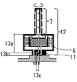
- a chemical vapor deposition apparatus (CVD furnace) 1 shown in FIGS. 9A, 9B and 9C is used as a schematic view. The outline of this device will be described.
- the CVD furnace 1 has a cylindrical chamber 2, a heater 3 provided inside the peripheral wall of the chamber 2, and a plurality of insert mounting plates 4 for mounting a large number of insert substrates (tool substrates) 20 in the chamber 2. It has a reaction vessel 5, a connection channel 11 provided at the lower part of the reaction vessel 5, and a preheating chamber 6 which is a preheating unit.
- the preheating chamber 6 is A mixed gas for Cr chloride gas generation introduced from the gas flow passage 82 is dispersed in the radial direction of the preheating chamber 6 via the connection flow passage 11 in a cylindrical shape and the lower portion thereof to generate a Cr chloride gas generation chamber 62 Space to introduce The Cr chloride gas generation chamber 62 is provided immediately above this space, has a cylindrical space whose center is cylindrical with the outer periphery of the cylinder matching the outer periphery of the preheating chamber 6, and concentric with the preheating chamber 6, A preheating chamber 61 (first preheating unit) which is formed concentrically with the preheating chamber 6 in a cylindrical space at the center of the Cr chloride gas generation chamber 62 and preheats the mixed gas a2 introduced from the gas flow passage 81; A mixing chamber 63 (mixing unit) located above the Cr chloride gas generation chamber 62 and the preheating chamber 61 and mixing a mixed gas a1 and a mixed gas a2 described later to form a mixed gas A;
- the preheating chamber 6 ie, at the axial center of the preheating chamber 61, there is a flow passage (second preheating portion) through which the mixed gas B introduced from the gas flow passage 91 penetrates in the height direction.
- the passage is connected to the outer passage of the pipe 7 at the top of the preheating chamber 6, which has the shortest length (550 mm) passing through the preheating unit.
- the flow path of the mixed gas A mixed in the mixing chamber 63 is provided to be connected to the central flow path 2 of the pipe 7 at the upper part of the preheating chamber 6.
- the mixed gas introduced from the gas flow channel 82 is introduced into the Cr chloride gas generator 62 in the preheating chamber 6 and reaches the temperature in the furnace at 750 ° C. or higher to react with the metal Cr in the same generation chamber to generate Cr chloride
- the mixed gas a 1 containing gas is introduced into the mixing chamber 63.
- mixed gas B is introduce
- the reaction gas A introduced from the gas flow paths 81 and 82 and penetrating the preheating chamber 61 is introduced into the central flow path of the pipe 7 and is introduced into the reaction vessel 5 from the nozzle holes 83a and 83b.
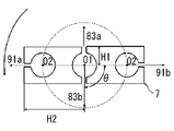
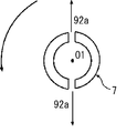
- the positional relationship between the nozzle holes 83a, 83b and the nozzle holes 91a, 91b is as shown in the gas jet nozzle cross-sectional view of FIG. 9C, the nozzle holes 91a, 91b have the rotational axis of the pipe 7 more than the nozzle holes 83a, 83b.
- H2 / H1 is 2 when the distance from the nozzle holes 91a and 91b to the rotation axis O1 is H2 and the distance from the nozzle holes 83a and 83b to the rotation axis O1 is H1.
- the jet direction of the nozzle holes 91a and 91b and the jet direction of the nozzle holes 83a and 83b form an angle of 90 degrees.
- connection channel 11, the preheating chamber 6 and the pipe 7 shown at 12 in FIG. 9B are configured to rotate at a speed of 2 rotations / minute, but in FIGS. 9A, 9B and 9C, this rotation is The illustration of the necessary configuration is omitted.
- the total length of the length of the gas flow path for obtaining the mixed gas a1 and the length of the gas flow path for the mixed gas a2 is the same as FIG. 9B.
- the length of the gas flow path of the mixed gas B which is the sum of 13a, 13b and 13c, is approximately four times the length of the gas flow path.
- Base material Milling insert (WDNW14520 made by Mitsubishi Hitachi Tool) made of WC base cemented carbide (10% by mass Co, 0.6% by mass Cr 3 C 2 , balance WC and unavoidable impurities) as a base material WC base cemented carbide (7% by mass Co, 0.6% by mass Cr 3 C 2 , 2.2% by mass ZrC, 3.3% by mass TaC, 0.2% by mass NbC, balance WC And an insert for evaluation of physical properties (made of ISO standard SNMN 120408).
- WDNW14520 made by Mitsubishi Hitachi Tool
- a titanium nitride film was formed as an intermediate film.
- the substrate was set in the CVD furnace 1 shown in FIG. 9A, and the temperature in the CVD furnace 1 was raised to 800 ° C. while flowing H 2 gas. Thereafter, 83.1% by volume of H 2 gas, 15.0% by volume of N 2 gas, 1.9% by volume of TiCl at 800 ° C.
- a mixed gas consisting of four gases was introduced into the preheating chamber 62, and flowed into the reaction vessel 5 at a flow rate of 67 L / min from the first nozzle holes 83a and 83b of the pipe 7 to form a titanium nitride film.
- Example 6 a titanium aluminum nitride film was formed as an intermediate film.
- the substrate was set in the CVD furnace 1 shown in FIG. 9A, and the temperature in the CVD furnace 1 was raised to 800 ° C. while flowing H 2 gas. Thereafter, at 800 ° C. and 4 kPa, gas volume of 81% by volume of TiCl 4 gas, 0.45% by volume of AlCl 3 gas, 7.50% by volume of N is introduced from the gas inlet of the preheating chamber 6 through the gas passage 81.
- a mixed gas consisting of 2 gas and 52.51% by volume of H 2 gas is introduced into the preheating chamber 62 and flows from the first nozzle holes 83 a and 83 b of the pipe 7 into the reaction vessel furnace 5 and the gas flow path 91
- a mixed gas consisting of 30.76% by volume of H 2 gas, 7.50% by volume of N 2 gas, 1.13% by volume of NH 3 gas is introduced into the second nozzle holes 91 a and 91 b of the pipe 7. It flowed into the reaction vessel 5 at a flow rate of 67 L / min to form a titanium aluminum nitride film.
- the coating conditions of the intermediate film are shown in Table 1.
- Step of obtaining mixed gas a1 After reducing the pressure in the CVD furnace 1 to 4kPa while introducing H 2 gas, the gas flow path 82 of the preheating chamber 6 shown in FIG. 9A, and a mixed gas of H 2 gas and HCl gas was kept to 400 ° C. .
- the Cr chloride gas generation chamber 62 of the preheating chamber 6 preheated to 800 ° C. is filled with Cr metal flakes (purity 99.99%, size 2 mm to 8 mm), and H 2 gas and HCl introduced from the gas flow path 82 A mixed gas of H 2 gas and a Cr chloride gas was generated to react with the mixed gas of gases, and a mixed gas a 1 was generated and introduced into the mixing chamber 63.
- a mixed gas a2 obtained by mixing H 2 gas and AlCl 3 gas was introduced into the preheating chamber 62 and preheated from the gas inlet of the preheating chamber 6 through the gas flow path 81. Then, the mixed gas a1 and the mixed gas a2 are mixed in the mixing chamber 63 to obtain the mixed gas A having a temperature near 800 ° C., which is the temperature of the preheating chamber. Then, the obtained mixed gas A was introduced from the first nozzle holes 83 a and 83 b of the pipe 7 into the reaction vessel furnace. The total flow rate of the mixed gas A was 48.75 L / min.
- a mixed gas B composed of H 2 gas, N 2 gas and NH 3 gas was introduced into the gas flow path 91 and introduced into the furnace from the second nozzle holes 91 a and 91 b of the pipe 7.
- the total flow rate of the mixed gas B was 30.25 L / min.
- Examples 1 to 8 and Comparative Example 1 were formed on the intermediate coatings described in Table 1 by the chemical vapor deposition method with each mixed gas composition shown in Table 2 to form nitrides of Al and Cr with a thickness of about 6 ⁇ m.
- the object was coated to produce a coated cutting tool.
- Comparative Example 1 does not satisfy the mixed gas composition defined in the embodiment of the present invention.
- the amount of generated Cr chloride gas and AlCl 3 gas was determined using the amount of HCl gas introduced into the Cr chloride gas generation chamber as the amount of Cr chloride gas to determine the composition of the mixed gas.
- the comparative example 2 produced the hard film using the CVD furnace shown to FIG. 10A and FIG. 10B.
- the configuration of this CVD furnace will be briefly described.
- 10A and 10B members denoted by the same reference numerals as those in FIGS. 9A and 9C represent the same members as those in these figures.
- the mixed gas is introduced from the gas flow passage 92, and the mixed gas is introduced into the reaction vessel 5 from the nozzle hole 92 a provided in the pipe 7.
- illustration of the structure required for rotation is abbreviate
- a titanium nitride film which is an intermediate film, was formed on the substrate under the same film forming conditions as in Example 1 as in the above example. Thereafter, the pressure in the CVD furnace 1 is lowered to 1 kPa while flowing H 2 gas at 800 ° C., and then H 2 gas, N 2 gas, CrCl 3 gas and AlCl 3 of the composition shown in Table 2 A mixed gas of gas and NH 3 gas was introduced into the reaction vessel 5 from the nozzle hole 92 a of the pipe 7. Thus, a coating of Al and Cr nitride having a thickness of about 6 ⁇ m was coated on the intermediate coating by chemical vapor deposition to produce a coated cutting tool.
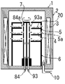
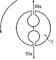
- the comparative example 3 produced the hard film using the CVD furnace shown to FIG. 11A and FIG. 11B.
- the configuration of this CVD furnace will be briefly described.
- 11A and 11B members denoted by the same reference numerals as those in FIGS. 9A and 9C represent the same members as those in these figures.
- the mixed gas introduced from the gas flow passage 84 is independent from the nozzle hole 94 a provided in the nozzle 7
- the mixed gas introduced from the gas passage 93 is independent from the nozzle hole 94 a provided in the nozzle 7.
- the pipe 7 rotates, illustration of the structure required for rotation is abbreviate
- a titanium nitride film which is an intermediate film, was formed on the substrate under the same film forming conditions as in Example 1 as in the above example. Thereafter, the pressure in the CVD furnace 1 is lowered to 4 kPa while flowing H 2 gas at 800 ° C., and then H 2 gas, N 2 gas, CrCl 3 gas and AlCl 3 of the composition shown in Table 2 A mixed gas A of gas is introduced into the reaction vessel 5 through the nozzle hole 84 a of the pipe 7, and a mixed gas composed of H 2 gas, N 2 gas and NH 3 gas in the gas flow path 93 of the composition shown in Table 2 B was introduced and introduced into the reaction vessel 5 from the nozzle hole 93 a of the pipe 7. Thus, a coating of Al and Cr nitride having a thickness of about 6 ⁇ m was coated on the intermediate coating by chemical vapor deposition to produce a coated cutting tool.
- the comparative example 4 produced the hard film using the same CVD furnace as the comparative example 3.
- the pressure in the CVD furnace 1 is lowered to 4 kPa while flowing H 2 gas at 800 ° C., and then H 2 gas, N 2 gas, CrCl 3 gas, and AlCl 3 having the composition shown in Table 2
- a mixed gas A of gas is introduced into the furnace through the nozzle hole 84a of the pipe 7 and mixed gas B consisting of H 2 gas, N 2 gas and NH 3 gas having the composition shown in Table 2 in the gas flow path 93
- mixed gas B consisting of H 2 gas, N 2 gas and NH 3 gas having the composition shown in Table 2 in the gas flow path 93
- a coating of Al and Cr nitride having a thickness of about 6 ⁇ m was coated on the intermediate coating by chemical vapor deposition to produce a coated
- Example 8 an upper layer was provided.
- the nitride film mainly composed of Al and Cr according to the present embodiment is formed, and then the bonding layer and the aluminum oxide layer are formed in this order.
- a bonding layer consisting of a Ti (CN) layer and a Ti (CNO) layer
- 63.5 volumes are obtained at 1000 ° C. and 16 kPa from the gas inlet of the preheating chamber 6 through the gas channel 81.
- a mixed gas consisting of 1% H 2 gas, 22.0% by volume N 2 gas, 3.2% by volume CH 4 gas, and 1.3% by volume TiCl 4 gas is introduced into the preheating chamber 62, the pipe 7
- the 10% by volume of H 2 gas is introduced into the gas flow path 91 while flowing from the first nozzle holes 83a and 83b into the reaction vessel furnace, and the second nozzle holes 91a and 91b of the pipe 7 enter the furnace.
- a 0.5 ⁇ m thick Ti (CN) layer was formed. 51.3% by volume of H 2 gas, 30.7% by volume of N 2 gas, 3.0% by volume of CH 4 gas, 1.2% by volume of TiCl 4 gas, continuously at 1000 ° C. and 16 kPa
- a mixed gas consisting of 0 volume% CO gas and 0.8 volume% CO 2 gas is introduced into the preheating chamber 62 and is flowed from the first nozzle holes 83 a and 83 b of the pipe 7 into the reaction vessel furnace, 10% by volume of H 2 gas was introduced into the gas flow channel 9 and flowed into the furnace from the second nozzle holes 91 a and 91 b of the pipe 7 to form a 0.5 ⁇ m thick Ti (CNO) layer.
- Comparative Example 5 was coated using an arc ion plating apparatus. An intermediate target is not provided, and an Al 70 Cr 30 (numerical value is atomic ratio) alloy target is used, a bias voltage of negative pressure applied to the substrate is ⁇ 100 V, nitrogen gas is introduced into the furnace, and the pressure in the furnace is A coated cutting tool was manufactured by coating Al and Cr nitride of about 3 ⁇ m at 3 Pa and a furnace temperature of 500 ° C.
- composition of hard film Cross section of the physical property evaluation insert (SNMN 120408) using an electron probe microanalyzer (EPMA, JXA-8500F manufactured by Nippon Denshi Co., Ltd.) under the conditions of an acceleration voltage of 10 kV, an irradiation current of 0.05 A and a beam diameter of 0.5 ⁇ m.
- the composition of the hard coating was determined from the average of the measured values obtained by measuring any five places at the center of the aluminum chromium nitride hard coating in the film thickness direction. The measurement results are shown in Table 3.
- the coated milling insert was attached to an indexable rotary tool (ASRT 5063R-4) with a set screw, and the tool life of the hard film was evaluated under the following milling conditions.
- the flank wear width of the hard coating was measured by observation with an optical microscope at a magnification of 100 times.
- the machining time up to the total cutting length when the maximum wear width on the flank surface exceeded 0.350 mm was measured in five minutes as the tool life. Processing conditions are shown below.
- the test results are shown in Table 3.
- FIG. 1A, FIG. 1B, and FIG. 1C respectively show SEM image photographs (magnification: 10,000 times) on a rake face of the insert for evaluating physical properties (SNMN 120408) according to Example 1, and a schematic diagram thereof. It can be seen from FIGS. 1A, 1B and 1C that Example 1 is composed of a collection of columnar particles grown in the film thickness direction with respect to the surface of the substrate. The details of the microstructure will be described later.
- the X-ray diffraction pattern of Example 1 is shown in FIG.
- a diffraction peak of the aluminum chromium chromium nitride hard coating of the fcc structure is observed together with the diffraction peak of WC of the WC base cemented carbide substrate.
- the aluminum chromium nitride hard film of Example 1 has a single structure of fcc structure.
- the X-ray diffraction intensity ratio TC (hkl) determined from the X-ray diffraction pattern of FIG. 8 is shown in Table 4.
- Table 5 and Table 6 show the X-ray diffraction intensity ratio TC (hkl) of Example 2 and Example 3, respectively.
- Tables 4 to 6 since the X-ray diffraction intensity ratio TC (422) can not be determined, it is indicated as "-".
- Example 1 confirmed that the X-ray diffraction intensity ratio TC (311) had the largest value as compared with the other X-ray diffraction intensity ratios. This is presumed to be the reason for the long tool life of Example 1 as compared to the other examples.
- Comparative Example 1 as shown in Table 7, the X-ray diffraction intensity ratio TC (311) is not the largest value as compared with other X-ray diffraction intensity ratios. In Table 7, since the X-ray diffraction intensity ratio TC (422) can not be determined, it is indicated as "-".
- Examples 1 to 8 all showed improved durability and chipping resistance and showed excellent durability. On the other hand, in all of Comparative Examples 1 to 5, film peeling occurred early. In all the comparative examples having poor durability, the value of the X-ray diffraction intensity ratio TC (311) was less than 1. On the other hand, in each of the examples in which the durability is excellent, the film structure is a structure composed of a collection of columnar particles having a fine film structure, and the value of the X-ray diffraction intensity ratio TC (311) is 1.30 or more. Among the examples, those having an X-ray diffraction intensity ratio TC (311) of 2 or more tended to be particularly excellent in durability. Moreover, when the value of TB / TA became large, it tended to be excellent in durability.
- Example 1 The TEM image photograph (magnification: 200,000 times) of the hard film concerning Example 1 is respectively shown in Drawing 2A, Drawing 2B, and Drawing 2C, and the schematic model diagram.
- FIG. 3A, FIG. 3B, and FIG. 3C are TEM image photographs (magnification: 2,000,000 times) which expanded the A section of FIG. 1A and FIG. 1C, respectively, and the schematic model diagrams.
- the hard film according to Example 1 has crystal grains having a portion composed of a laminated structure and a portion composed of a single layer structure even in the microstructure observed at a higher magnification. Was confirmed.
- FIGS. 4A and 4B show nanobeam diffraction patterns of part B (single layer structure) of FIGS. 3A and 3C. As shown to FIG. 4A and FIG. 4B, the part which consists of single layer structure was comprised from the fcc structure.
- FIG. 5A, FIG. 5B, and FIG. 5C are the TEM image photography (magnification 4,000,000 times) which expanded C part (lamination
- the relatively dark phase is a nitride of Al and Cr having a high content ratio of Al
- the relatively bright phase is a nitride of Al and Cr having a low content ratio of Al.
- FIG. 6A and FIG. 6B show nanobeam diffraction patterns of a portion E (laminated structure) of FIGS. 5A and 5C.
- FIG. 6A, FIG. 6B and FIG. 7A, FIG. 7B it was confirmed that each layer of the laminated structure was also composed of the fcc structure.
- the content ratio of Al was 60 atomic percent or more and 90 atomic percent or less.
- the Al and Cr nitride portion having a relatively high Al content ratio has an Al content ratio of 60 atomic% or more and 95 atomic% or less, and the relative Al content is In the portion of the nitride of Al and Cr having a low ratio, the content ratio of Al was 20 atomic percent or more and 50 atomic percent or less. As a whole of the portion composed of the laminated structure, the content ratio of Al was lower than that of the portion composed of the single layer structure.
- the microstructure of the hard film according to the first embodiment of the present invention has a structure in which crystal grains having a portion of a single layer structure having a relatively high Al content ratio and a laminated portion having a relatively low Al content ratio It was dispersed.
Landscapes
- Chemical & Material Sciences (AREA)
- Engineering & Computer Science (AREA)
- Mechanical Engineering (AREA)
- Materials Engineering (AREA)
- Metallurgy (AREA)
- Organic Chemistry (AREA)
- Chemical Kinetics & Catalysis (AREA)
- General Chemical & Material Sciences (AREA)
- Inorganic Chemistry (AREA)
- Physics & Mathematics (AREA)
- Thermal Sciences (AREA)
- Crystallography & Structural Chemistry (AREA)
- Ceramic Engineering (AREA)
- Electrochemistry (AREA)
- Chemical Vapour Deposition (AREA)
- Cutting Tools, Boring Holders, And Turrets (AREA)
- Drilling Tools (AREA)
- Milling, Broaching, Filing, Reaming, And Others (AREA)
Priority Applications (5)
| Application Number | Priority Date | Filing Date | Title |
|---|---|---|---|
| US16/639,901 US11541461B2 (en) | 2017-11-16 | 2018-11-09 | Coated cutting tool, and method and system for manufacturing the same by chemical vapor deposition |
| EP18879901.9A EP3711883A4 (en) | 2017-11-16 | 2018-11-09 | COATED CUTTING TOOL, MANUFACTURING PROCESS AND DEVICE FOR CHEMICAL GAS PHASE SEPARATION FOR IT |
| JP2019520652A JP6617942B2 (ja) | 2017-11-16 | 2018-11-09 | 被覆切削工具およびその製造方法 |
| CN201880054794.6A CN111032259B (zh) | 2017-11-16 | 2018-11-09 | 包覆切削工具及其制造方法和化学气相沉积装置 |
| KR1020207000897A KR102571881B1 (ko) | 2017-11-16 | 2018-11-09 | 피복 절삭 공구 그리고 그 제조 방법 및 화학 증착 장치 |
Applications Claiming Priority (2)
| Application Number | Priority Date | Filing Date | Title |
|---|---|---|---|
| JP2017221016 | 2017-11-16 | ||
| JP2017-221016 | 2017-11-16 |
Publications (1)
| Publication Number | Publication Date |
|---|---|
| WO2019098130A1 true WO2019098130A1 (ja) | 2019-05-23 |
Family
ID=66540217
Family Applications (1)
| Application Number | Title | Priority Date | Filing Date |
|---|---|---|---|
| PCT/JP2018/041620 WO2019098130A1 (ja) | 2017-11-16 | 2018-11-09 | 被覆切削工具ならびにその製造方法および化学蒸着装置 |
Country Status (6)
| Country | Link |
|---|---|
| US (1) | US11541461B2 (ko) |
| EP (1) | EP3711883A4 (ko) |
| JP (3) | JP6617942B2 (ko) |
| KR (1) | KR102571881B1 (ko) |
| CN (1) | CN111032259B (ko) |
| WO (1) | WO2019098130A1 (ko) |
Cited By (3)
| Publication number | Priority date | Publication date | Assignee | Title |
|---|---|---|---|---|
| JP2020078864A (ja) * | 2017-11-16 | 2020-05-28 | 株式会社Moldino | 被覆切削工具ならびにその製造方法 |
| JP2020157377A (ja) * | 2019-03-25 | 2020-10-01 | 株式会社Moldino | 被覆工具 |
| JP7486713B2 (ja) | 2020-12-21 | 2024-05-20 | 株式会社Moldino | 被覆工具 |
Families Citing this family (3)
| Publication number | Priority date | Publication date | Assignee | Title |
|---|---|---|---|---|
| JP6930446B2 (ja) * | 2018-01-31 | 2021-09-01 | 株式会社Moldino | 硬質皮膜、硬質皮膜被覆工具及びその製造方法 |
| JP6798534B2 (ja) * | 2018-09-11 | 2020-12-09 | 株式会社タンガロイ | 被覆切削工具 |
| TW202330985A (zh) * | 2021-09-29 | 2023-08-01 | 荷蘭商Asm Ip私人控股有限公司 | 氣體注入器及垂直式爐管 |
Citations (3)
| Publication number | Priority date | Publication date | Assignee | Title |
|---|---|---|---|---|
| WO2016158717A1 (ja) * | 2015-03-27 | 2016-10-06 | 株式会社タンガロイ | 被覆切削工具 |
| WO2017073787A1 (ja) * | 2015-10-30 | 2017-05-04 | 三菱マテリアル株式会社 | 表面被覆切削工具およびその製造方法 |
| JP2017080883A (ja) | 2015-10-30 | 2017-05-18 | 三菱マテリアル株式会社 | 硬質被覆層がすぐれた耐チッピング性を発揮する表面被覆切削工具 |
Family Cites Families (16)
| Publication number | Priority date | Publication date | Assignee | Title |
|---|---|---|---|---|
| JP3658949B2 (ja) * | 1997-11-04 | 2005-06-15 | 住友電気工業株式会社 | 被覆超硬合金 |
| JP2003266212A (ja) | 2002-03-19 | 2003-09-24 | Hitachi Tool Engineering Ltd | クロム含有膜被覆工具 |
| JP2007168032A (ja) | 2005-12-22 | 2007-07-05 | Mitsubishi Materials Corp | 高速重切削条件で硬質被覆層がすぐれた耐摩耗性および耐チッピング性を発揮する表面被覆切削工具 |
| AU2007302162B2 (en) * | 2006-09-26 | 2012-06-28 | Oerlikon Trading Ag, Truebbach | Workpiece with hard coating |
| US7597511B2 (en) * | 2007-12-28 | 2009-10-06 | Mitsubishi Materials Corporation | Surface-coated cutting tool with hard coating layer having excellent abrasion resistance |
| JP5206167B2 (ja) | 2008-07-04 | 2013-06-12 | 日立ツール株式会社 | 硬質皮膜被覆切削工具 |
| JP2013116551A (ja) | 2011-10-31 | 2013-06-13 | Mitsubishi Materials Corp | 耐酸化性と耐摩耗性にすぐれた表面被覆工具 |
| JP5344204B2 (ja) * | 2012-03-05 | 2013-11-20 | 三菱マテリアル株式会社 | 表面被覆切削工具 |
| JP5618429B2 (ja) | 2012-12-28 | 2014-11-05 | 住友電工ハードメタル株式会社 | 表面被覆部材およびその製造方法 |
| JP2014198362A (ja) | 2013-03-29 | 2014-10-23 | 三菱マテリアル株式会社 | 表面被覆切削工具 |
| WO2015141743A1 (ja) * | 2014-03-18 | 2015-09-24 | 日立金属株式会社 | 被覆切削工具及びその製造方法 |
| JP6778413B2 (ja) * | 2015-10-30 | 2020-11-04 | 三菱マテリアル株式会社 | 硬質被覆層がすぐれた耐チッピング性、耐摩耗性を発揮する表面被覆切削工具 |
| JP6931452B2 (ja) | 2015-10-30 | 2021-09-08 | 三菱マテリアル株式会社 | 硬質被覆層がすぐれた耐摩耗性および耐チッピング性を発揮する表面被覆切削工具 |
| CN108291300B (zh) | 2015-11-25 | 2020-09-08 | 三菱日立工具株式会社 | 氮化钛铝硬质皮膜、硬质皮膜包覆工具及它们的制造方法 |
| US10918756B2 (en) * | 2016-11-02 | 2021-02-16 | Dow Global Technologies Llc | Solid non-aqueous gel air odorizer |
| EP3711883A4 (en) * | 2017-11-16 | 2021-08-25 | MOLDINO Tool Engineering, Ltd. | COATED CUTTING TOOL, MANUFACTURING PROCESS AND DEVICE FOR CHEMICAL GAS PHASE SEPARATION FOR IT |
-
2018
- 2018-11-09 EP EP18879901.9A patent/EP3711883A4/en active Pending
- 2018-11-09 CN CN201880054794.6A patent/CN111032259B/zh active Active
- 2018-11-09 US US16/639,901 patent/US11541461B2/en active Active
- 2018-11-09 KR KR1020207000897A patent/KR102571881B1/ko active IP Right Grant
- 2018-11-09 JP JP2019520652A patent/JP6617942B2/ja active Active
- 2018-11-09 WO PCT/JP2018/041620 patent/WO2019098130A1/ja unknown
-
2019
- 2019-09-13 JP JP2019167350A patent/JP6660608B2/ja active Active
- 2019-10-21 JP JP2019191969A patent/JP7022105B2/ja active Active
Patent Citations (3)
| Publication number | Priority date | Publication date | Assignee | Title |
|---|---|---|---|---|
| WO2016158717A1 (ja) * | 2015-03-27 | 2016-10-06 | 株式会社タンガロイ | 被覆切削工具 |
| WO2017073787A1 (ja) * | 2015-10-30 | 2017-05-04 | 三菱マテリアル株式会社 | 表面被覆切削工具およびその製造方法 |
| JP2017080883A (ja) | 2015-10-30 | 2017-05-18 | 三菱マテリアル株式会社 | 硬質被覆層がすぐれた耐チッピング性を発揮する表面被覆切削工具 |
Cited By (4)
| Publication number | Priority date | Publication date | Assignee | Title |
|---|---|---|---|---|
| JP2020078864A (ja) * | 2017-11-16 | 2020-05-28 | 株式会社Moldino | 被覆切削工具ならびにその製造方法 |
| JP2020157377A (ja) * | 2019-03-25 | 2020-10-01 | 株式会社Moldino | 被覆工具 |
| JP7250243B2 (ja) | 2019-03-25 | 2023-04-03 | 株式会社Moldino | 被覆工具 |
| JP7486713B2 (ja) | 2020-12-21 | 2024-05-20 | 株式会社Moldino | 被覆工具 |
Also Published As
| Publication number | Publication date |
|---|---|
| KR102571881B1 (ko) | 2023-08-28 |
| JP2019214796A (ja) | 2019-12-19 |
| CN111032259B (zh) | 2023-04-07 |
| CN111032259A (zh) | 2020-04-17 |
| KR20200081354A (ko) | 2020-07-07 |
| JP6660608B2 (ja) | 2020-03-11 |
| EP3711883A1 (en) | 2020-09-23 |
| JP6617942B2 (ja) | 2019-12-11 |
| JPWO2019098130A1 (ja) | 2019-11-14 |
| EP3711883A4 (en) | 2021-08-25 |
| US20210354204A1 (en) | 2021-11-18 |
| JP7022105B2 (ja) | 2022-02-17 |
| US11541461B2 (en) | 2023-01-03 |
| JP2020078864A (ja) | 2020-05-28 |
Similar Documents
| Publication | Publication Date | Title |
|---|---|---|
| WO2019098130A1 (ja) | 被覆切削工具ならびにその製造方法および化学蒸着装置 | |
| US10767258B2 (en) | Hard titanium aluminum nitride coating, hard-coated tool, and their production methods | |
| CN107761073B (zh) | 表面被覆部件及其制造方法 | |
| JP7250243B2 (ja) | 被覆工具 | |
| JP6848970B2 (ja) | 硬質皮膜、硬質皮膜被覆工具及びそれらの製造方法 | |
| CN111886093B (zh) | 表面被覆切削工具及其制造方法 | |
| JP7247452B2 (ja) | 被覆工具 | |
| KR102094055B1 (ko) | 표면 피복 부재 및 그 제조 방법 | |
| CN111902229B (zh) | 表面被覆切削工具及其制造方法 | |
| JP6910598B2 (ja) | 被覆切削工具 | |
| CN114173972B (zh) | 切削工具 | |
| WO2022230362A1 (ja) | 切削工具 | |
| WO2022230361A1 (ja) | 切削工具 | |
| CN112839760B (zh) | 切削工具 | |
| WO2022230360A1 (ja) | 切削工具 | |
| JP6565093B1 (ja) | 表面被覆切削工具およびその製造方法 | |
| WO2022230363A1 (ja) | 切削工具及びその製造方法 | |
| JP2022171408A (ja) | 切削工具 | |
| JP2022171411A (ja) | 切削工具 | |
| WO2019181135A1 (ja) | 表面被覆切削工具およびその製造方法 | |
| JP2022171409A (ja) | 切削工具 | |
| JP2022171410A (ja) | 切削工具 | |
| JP2022171412A (ja) | 切削工具 |
Legal Events
| Date | Code | Title | Description |
|---|---|---|---|
| ENP | Entry into the national phase |
Ref document number: 2019520652 Country of ref document: JP Kind code of ref document: A |
|
| 121 | Ep: the epo has been informed by wipo that ep was designated in this application |
Ref document number: 18879901 Country of ref document: EP Kind code of ref document: A1 |
|
| NENP | Non-entry into the national phase |
Ref country code: DE |
|
| ENP | Entry into the national phase |
Ref document number: 2018879901 Country of ref document: EP Effective date: 20200616 |