WO2019098130A1 - 被覆切削工具ならびにその製造方法および化学蒸着装置 - Google Patents
被覆切削工具ならびにその製造方法および化学蒸着装置 Download PDFInfo
- Publication number
- WO2019098130A1 WO2019098130A1 PCT/JP2018/041620 JP2018041620W WO2019098130A1 WO 2019098130 A1 WO2019098130 A1 WO 2019098130A1 JP 2018041620 W JP2018041620 W JP 2018041620W WO 2019098130 A1 WO2019098130 A1 WO 2019098130A1
- Authority
- WO
- WIPO (PCT)
- Prior art keywords
- gas
- mixed gas
- cutting tool
- coated cutting
- ray diffraction
- Prior art date
Links
Images


Classifications
-
- B—PERFORMING OPERATIONS; TRANSPORTING
- B23—MACHINE TOOLS; METAL-WORKING NOT OTHERWISE PROVIDED FOR
- B23B—TURNING; BORING
- B23B27/00—Tools for turning or boring machines; Tools of a similar kind in general; Accessories therefor
- B23B27/14—Cutting tools of which the bits or tips or cutting inserts are of special material
- B23B27/148—Composition of the cutting inserts
-
- B—PERFORMING OPERATIONS; TRANSPORTING
- B23—MACHINE TOOLS; METAL-WORKING NOT OTHERWISE PROVIDED FOR
- B23C—MILLING
- B23C5/00—Milling-cutters
- B23C5/16—Milling-cutters characterised by physical features other than shape
-
- C—CHEMISTRY; METALLURGY
- C21—METALLURGY OF IRON
- C21D—MODIFYING THE PHYSICAL STRUCTURE OF FERROUS METALS; GENERAL DEVICES FOR HEAT TREATMENT OF FERROUS OR NON-FERROUS METALS OR ALLOYS; MAKING METAL MALLEABLE, e.g. BY DECARBURISATION OR TEMPERING
- C21D9/00—Heat treatment, e.g. annealing, hardening, quenching or tempering, adapted for particular articles; Furnaces therefor
- C21D9/22—Heat treatment, e.g. annealing, hardening, quenching or tempering, adapted for particular articles; Furnaces therefor for drills; for milling cutters; for machine cutting tools
-
- C—CHEMISTRY; METALLURGY
- C22—METALLURGY; FERROUS OR NON-FERROUS ALLOYS; TREATMENT OF ALLOYS OR NON-FERROUS METALS
- C22C—ALLOYS
- C22C21/00—Alloys based on aluminium
-
- C—CHEMISTRY; METALLURGY
- C22—METALLURGY; FERROUS OR NON-FERROUS ALLOYS; TREATMENT OF ALLOYS OR NON-FERROUS METALS
- C22F—CHANGING THE PHYSICAL STRUCTURE OF NON-FERROUS METALS AND NON-FERROUS ALLOYS
- C22F1/00—Changing the physical structure of non-ferrous metals or alloys by heat treatment or by hot or cold working
- C22F1/04—Changing the physical structure of non-ferrous metals or alloys by heat treatment or by hot or cold working of aluminium or alloys based thereon
-
- C—CHEMISTRY; METALLURGY
- C23—COATING METALLIC MATERIAL; COATING MATERIAL WITH METALLIC MATERIAL; CHEMICAL SURFACE TREATMENT; DIFFUSION TREATMENT OF METALLIC MATERIAL; COATING BY VACUUM EVAPORATION, BY SPUTTERING, BY ION IMPLANTATION OR BY CHEMICAL VAPOUR DEPOSITION, IN GENERAL; INHIBITING CORROSION OF METALLIC MATERIAL OR INCRUSTATION IN GENERAL
- C23C—COATING METALLIC MATERIAL; COATING MATERIAL WITH METALLIC MATERIAL; SURFACE TREATMENT OF METALLIC MATERIAL BY DIFFUSION INTO THE SURFACE, BY CHEMICAL CONVERSION OR SUBSTITUTION; COATING BY VACUUM EVAPORATION, BY SPUTTERING, BY ION IMPLANTATION OR BY CHEMICAL VAPOUR DEPOSITION, IN GENERAL
- C23C16/00—Chemical coating by decomposition of gaseous compounds, without leaving reaction products of surface material in the coating, i.e. chemical vapour deposition [CVD] processes
- C23C16/02—Pretreatment of the material to be coated
- C23C16/0272—Deposition of sub-layers, e.g. to promote the adhesion of the main coating
-
- C—CHEMISTRY; METALLURGY
- C23—COATING METALLIC MATERIAL; COATING MATERIAL WITH METALLIC MATERIAL; CHEMICAL SURFACE TREATMENT; DIFFUSION TREATMENT OF METALLIC MATERIAL; COATING BY VACUUM EVAPORATION, BY SPUTTERING, BY ION IMPLANTATION OR BY CHEMICAL VAPOUR DEPOSITION, IN GENERAL; INHIBITING CORROSION OF METALLIC MATERIAL OR INCRUSTATION IN GENERAL
- C23C—COATING METALLIC MATERIAL; COATING MATERIAL WITH METALLIC MATERIAL; SURFACE TREATMENT OF METALLIC MATERIAL BY DIFFUSION INTO THE SURFACE, BY CHEMICAL CONVERSION OR SUBSTITUTION; COATING BY VACUUM EVAPORATION, BY SPUTTERING, BY ION IMPLANTATION OR BY CHEMICAL VAPOUR DEPOSITION, IN GENERAL
- C23C16/00—Chemical coating by decomposition of gaseous compounds, without leaving reaction products of surface material in the coating, i.e. chemical vapour deposition [CVD] processes
- C23C16/22—Chemical coating by decomposition of gaseous compounds, without leaving reaction products of surface material in the coating, i.e. chemical vapour deposition [CVD] processes characterised by the deposition of inorganic material, other than metallic material
- C23C16/30—Deposition of compounds, mixtures or solid solutions, e.g. borides, carbides, nitrides
- C23C16/34—Nitrides
-
- C—CHEMISTRY; METALLURGY
- C23—COATING METALLIC MATERIAL; COATING MATERIAL WITH METALLIC MATERIAL; CHEMICAL SURFACE TREATMENT; DIFFUSION TREATMENT OF METALLIC MATERIAL; COATING BY VACUUM EVAPORATION, BY SPUTTERING, BY ION IMPLANTATION OR BY CHEMICAL VAPOUR DEPOSITION, IN GENERAL; INHIBITING CORROSION OF METALLIC MATERIAL OR INCRUSTATION IN GENERAL
- C23C—COATING METALLIC MATERIAL; COATING MATERIAL WITH METALLIC MATERIAL; SURFACE TREATMENT OF METALLIC MATERIAL BY DIFFUSION INTO THE SURFACE, BY CHEMICAL CONVERSION OR SUBSTITUTION; COATING BY VACUUM EVAPORATION, BY SPUTTERING, BY ION IMPLANTATION OR BY CHEMICAL VAPOUR DEPOSITION, IN GENERAL
- C23C16/00—Chemical coating by decomposition of gaseous compounds, without leaving reaction products of surface material in the coating, i.e. chemical vapour deposition [CVD] processes
- C23C16/44—Chemical coating by decomposition of gaseous compounds, without leaving reaction products of surface material in the coating, i.e. chemical vapour deposition [CVD] processes characterised by the method of coating
- C23C16/448—Chemical coating by decomposition of gaseous compounds, without leaving reaction products of surface material in the coating, i.e. chemical vapour deposition [CVD] processes characterised by the method of coating characterised by the method used for generating reactive gas streams, e.g. by evaporation or sublimation of precursor materials
- C23C16/4488—Chemical coating by decomposition of gaseous compounds, without leaving reaction products of surface material in the coating, i.e. chemical vapour deposition [CVD] processes characterised by the method of coating characterised by the method used for generating reactive gas streams, e.g. by evaporation or sublimation of precursor materials by in situ generation of reactive gas by chemical or electrochemical reaction
-
- C—CHEMISTRY; METALLURGY
- C23—COATING METALLIC MATERIAL; COATING MATERIAL WITH METALLIC MATERIAL; CHEMICAL SURFACE TREATMENT; DIFFUSION TREATMENT OF METALLIC MATERIAL; COATING BY VACUUM EVAPORATION, BY SPUTTERING, BY ION IMPLANTATION OR BY CHEMICAL VAPOUR DEPOSITION, IN GENERAL; INHIBITING CORROSION OF METALLIC MATERIAL OR INCRUSTATION IN GENERAL
- C23C—COATING METALLIC MATERIAL; COATING MATERIAL WITH METALLIC MATERIAL; SURFACE TREATMENT OF METALLIC MATERIAL BY DIFFUSION INTO THE SURFACE, BY CHEMICAL CONVERSION OR SUBSTITUTION; COATING BY VACUUM EVAPORATION, BY SPUTTERING, BY ION IMPLANTATION OR BY CHEMICAL VAPOUR DEPOSITION, IN GENERAL
- C23C16/00—Chemical coating by decomposition of gaseous compounds, without leaving reaction products of surface material in the coating, i.e. chemical vapour deposition [CVD] processes
- C23C16/44—Chemical coating by decomposition of gaseous compounds, without leaving reaction products of surface material in the coating, i.e. chemical vapour deposition [CVD] processes characterised by the method of coating
- C23C16/455—Chemical coating by decomposition of gaseous compounds, without leaving reaction products of surface material in the coating, i.e. chemical vapour deposition [CVD] processes characterised by the method of coating characterised by the method used for introducing gases into reaction chamber or for modifying gas flows in reaction chamber
- C23C16/45502—Flow conditions in reaction chamber
- C23C16/45508—Radial flow
-
- C—CHEMISTRY; METALLURGY
- C23—COATING METALLIC MATERIAL; COATING MATERIAL WITH METALLIC MATERIAL; CHEMICAL SURFACE TREATMENT; DIFFUSION TREATMENT OF METALLIC MATERIAL; COATING BY VACUUM EVAPORATION, BY SPUTTERING, BY ION IMPLANTATION OR BY CHEMICAL VAPOUR DEPOSITION, IN GENERAL; INHIBITING CORROSION OF METALLIC MATERIAL OR INCRUSTATION IN GENERAL
- C23C—COATING METALLIC MATERIAL; COATING MATERIAL WITH METALLIC MATERIAL; SURFACE TREATMENT OF METALLIC MATERIAL BY DIFFUSION INTO THE SURFACE, BY CHEMICAL CONVERSION OR SUBSTITUTION; COATING BY VACUUM EVAPORATION, BY SPUTTERING, BY ION IMPLANTATION OR BY CHEMICAL VAPOUR DEPOSITION, IN GENERAL
- C23C16/00—Chemical coating by decomposition of gaseous compounds, without leaving reaction products of surface material in the coating, i.e. chemical vapour deposition [CVD] processes
- C23C16/44—Chemical coating by decomposition of gaseous compounds, without leaving reaction products of surface material in the coating, i.e. chemical vapour deposition [CVD] processes characterised by the method of coating
- C23C16/455—Chemical coating by decomposition of gaseous compounds, without leaving reaction products of surface material in the coating, i.e. chemical vapour deposition [CVD] processes characterised by the method of coating characterised by the method used for introducing gases into reaction chamber or for modifying gas flows in reaction chamber
- C23C16/45512—Premixing before introduction in the reaction chamber
-
- C—CHEMISTRY; METALLURGY
- C23—COATING METALLIC MATERIAL; COATING MATERIAL WITH METALLIC MATERIAL; CHEMICAL SURFACE TREATMENT; DIFFUSION TREATMENT OF METALLIC MATERIAL; COATING BY VACUUM EVAPORATION, BY SPUTTERING, BY ION IMPLANTATION OR BY CHEMICAL VAPOUR DEPOSITION, IN GENERAL; INHIBITING CORROSION OF METALLIC MATERIAL OR INCRUSTATION IN GENERAL
- C23C—COATING METALLIC MATERIAL; COATING MATERIAL WITH METALLIC MATERIAL; SURFACE TREATMENT OF METALLIC MATERIAL BY DIFFUSION INTO THE SURFACE, BY CHEMICAL CONVERSION OR SUBSTITUTION; COATING BY VACUUM EVAPORATION, BY SPUTTERING, BY ION IMPLANTATION OR BY CHEMICAL VAPOUR DEPOSITION, IN GENERAL
- C23C16/00—Chemical coating by decomposition of gaseous compounds, without leaving reaction products of surface material in the coating, i.e. chemical vapour deposition [CVD] processes
- C23C16/44—Chemical coating by decomposition of gaseous compounds, without leaving reaction products of surface material in the coating, i.e. chemical vapour deposition [CVD] processes characterised by the method of coating
- C23C16/455—Chemical coating by decomposition of gaseous compounds, without leaving reaction products of surface material in the coating, i.e. chemical vapour deposition [CVD] processes characterised by the method of coating characterised by the method used for introducing gases into reaction chamber or for modifying gas flows in reaction chamber
- C23C16/45561—Gas plumbing upstream of the reaction chamber
-
- C—CHEMISTRY; METALLURGY
- C23—COATING METALLIC MATERIAL; COATING MATERIAL WITH METALLIC MATERIAL; CHEMICAL SURFACE TREATMENT; DIFFUSION TREATMENT OF METALLIC MATERIAL; COATING BY VACUUM EVAPORATION, BY SPUTTERING, BY ION IMPLANTATION OR BY CHEMICAL VAPOUR DEPOSITION, IN GENERAL; INHIBITING CORROSION OF METALLIC MATERIAL OR INCRUSTATION IN GENERAL
- C23C—COATING METALLIC MATERIAL; COATING MATERIAL WITH METALLIC MATERIAL; SURFACE TREATMENT OF METALLIC MATERIAL BY DIFFUSION INTO THE SURFACE, BY CHEMICAL CONVERSION OR SUBSTITUTION; COATING BY VACUUM EVAPORATION, BY SPUTTERING, BY ION IMPLANTATION OR BY CHEMICAL VAPOUR DEPOSITION, IN GENERAL
- C23C16/00—Chemical coating by decomposition of gaseous compounds, without leaving reaction products of surface material in the coating, i.e. chemical vapour deposition [CVD] processes
- C23C16/44—Chemical coating by decomposition of gaseous compounds, without leaving reaction products of surface material in the coating, i.e. chemical vapour deposition [CVD] processes characterised by the method of coating
- C23C16/455—Chemical coating by decomposition of gaseous compounds, without leaving reaction products of surface material in the coating, i.e. chemical vapour deposition [CVD] processes characterised by the method of coating characterised by the method used for introducing gases into reaction chamber or for modifying gas flows in reaction chamber
- C23C16/45563—Gas nozzles
- C23C16/45574—Nozzles for more than one gas
-
- C—CHEMISTRY; METALLURGY
- C23—COATING METALLIC MATERIAL; COATING MATERIAL WITH METALLIC MATERIAL; CHEMICAL SURFACE TREATMENT; DIFFUSION TREATMENT OF METALLIC MATERIAL; COATING BY VACUUM EVAPORATION, BY SPUTTERING, BY ION IMPLANTATION OR BY CHEMICAL VAPOUR DEPOSITION, IN GENERAL; INHIBITING CORROSION OF METALLIC MATERIAL OR INCRUSTATION IN GENERAL
- C23C—COATING METALLIC MATERIAL; COATING MATERIAL WITH METALLIC MATERIAL; SURFACE TREATMENT OF METALLIC MATERIAL BY DIFFUSION INTO THE SURFACE, BY CHEMICAL CONVERSION OR SUBSTITUTION; COATING BY VACUUM EVAPORATION, BY SPUTTERING, BY ION IMPLANTATION OR BY CHEMICAL VAPOUR DEPOSITION, IN GENERAL
- C23C16/00—Chemical coating by decomposition of gaseous compounds, without leaving reaction products of surface material in the coating, i.e. chemical vapour deposition [CVD] processes
- C23C16/44—Chemical coating by decomposition of gaseous compounds, without leaving reaction products of surface material in the coating, i.e. chemical vapour deposition [CVD] processes characterised by the method of coating
- C23C16/455—Chemical coating by decomposition of gaseous compounds, without leaving reaction products of surface material in the coating, i.e. chemical vapour deposition [CVD] processes characterised by the method of coating characterised by the method used for introducing gases into reaction chamber or for modifying gas flows in reaction chamber
- C23C16/45563—Gas nozzles
- C23C16/45576—Coaxial inlets for each gas
-
- C—CHEMISTRY; METALLURGY
- C23—COATING METALLIC MATERIAL; COATING MATERIAL WITH METALLIC MATERIAL; CHEMICAL SURFACE TREATMENT; DIFFUSION TREATMENT OF METALLIC MATERIAL; COATING BY VACUUM EVAPORATION, BY SPUTTERING, BY ION IMPLANTATION OR BY CHEMICAL VAPOUR DEPOSITION, IN GENERAL; INHIBITING CORROSION OF METALLIC MATERIAL OR INCRUSTATION IN GENERAL
- C23C—COATING METALLIC MATERIAL; COATING MATERIAL WITH METALLIC MATERIAL; SURFACE TREATMENT OF METALLIC MATERIAL BY DIFFUSION INTO THE SURFACE, BY CHEMICAL CONVERSION OR SUBSTITUTION; COATING BY VACUUM EVAPORATION, BY SPUTTERING, BY ION IMPLANTATION OR BY CHEMICAL VAPOUR DEPOSITION, IN GENERAL
- C23C16/00—Chemical coating by decomposition of gaseous compounds, without leaving reaction products of surface material in the coating, i.e. chemical vapour deposition [CVD] processes
- C23C16/44—Chemical coating by decomposition of gaseous compounds, without leaving reaction products of surface material in the coating, i.e. chemical vapour deposition [CVD] processes characterised by the method of coating
- C23C16/455—Chemical coating by decomposition of gaseous compounds, without leaving reaction products of surface material in the coating, i.e. chemical vapour deposition [CVD] processes characterised by the method of coating characterised by the method used for introducing gases into reaction chamber or for modifying gas flows in reaction chamber
- C23C16/45563—Gas nozzles
- C23C16/45578—Elongated nozzles, tubes with holes
-
- C—CHEMISTRY; METALLURGY
- C23—COATING METALLIC MATERIAL; COATING MATERIAL WITH METALLIC MATERIAL; CHEMICAL SURFACE TREATMENT; DIFFUSION TREATMENT OF METALLIC MATERIAL; COATING BY VACUUM EVAPORATION, BY SPUTTERING, BY ION IMPLANTATION OR BY CHEMICAL VAPOUR DEPOSITION, IN GENERAL; INHIBITING CORROSION OF METALLIC MATERIAL OR INCRUSTATION IN GENERAL
- C23C—COATING METALLIC MATERIAL; COATING MATERIAL WITH METALLIC MATERIAL; SURFACE TREATMENT OF METALLIC MATERIAL BY DIFFUSION INTO THE SURFACE, BY CHEMICAL CONVERSION OR SUBSTITUTION; COATING BY VACUUM EVAPORATION, BY SPUTTERING, BY ION IMPLANTATION OR BY CHEMICAL VAPOUR DEPOSITION, IN GENERAL
- C23C16/00—Chemical coating by decomposition of gaseous compounds, without leaving reaction products of surface material in the coating, i.e. chemical vapour deposition [CVD] processes
- C23C16/56—After-treatment
-
- C—CHEMISTRY; METALLURGY
- C23—COATING METALLIC MATERIAL; COATING MATERIAL WITH METALLIC MATERIAL; CHEMICAL SURFACE TREATMENT; DIFFUSION TREATMENT OF METALLIC MATERIAL; COATING BY VACUUM EVAPORATION, BY SPUTTERING, BY ION IMPLANTATION OR BY CHEMICAL VAPOUR DEPOSITION, IN GENERAL; INHIBITING CORROSION OF METALLIC MATERIAL OR INCRUSTATION IN GENERAL
- C23C—COATING METALLIC MATERIAL; COATING MATERIAL WITH METALLIC MATERIAL; SURFACE TREATMENT OF METALLIC MATERIAL BY DIFFUSION INTO THE SURFACE, BY CHEMICAL CONVERSION OR SUBSTITUTION; COATING BY VACUUM EVAPORATION, BY SPUTTERING, BY ION IMPLANTATION OR BY CHEMICAL VAPOUR DEPOSITION, IN GENERAL
- C23C28/00—Coating for obtaining at least two superposed coatings either by methods not provided for in a single one of groups C23C2/00 - C23C26/00 or by combinations of methods provided for in subclasses C23C and C25C or C25D
- C23C28/04—Coating for obtaining at least two superposed coatings either by methods not provided for in a single one of groups C23C2/00 - C23C26/00 or by combinations of methods provided for in subclasses C23C and C25C or C25D only coatings of inorganic non-metallic material
- C23C28/042—Coating for obtaining at least two superposed coatings either by methods not provided for in a single one of groups C23C2/00 - C23C26/00 or by combinations of methods provided for in subclasses C23C and C25C or C25D only coatings of inorganic non-metallic material including a refractory ceramic layer, e.g. refractory metal oxides, ZrO2, rare earth oxides
-
- C—CHEMISTRY; METALLURGY
- C23—COATING METALLIC MATERIAL; COATING MATERIAL WITH METALLIC MATERIAL; CHEMICAL SURFACE TREATMENT; DIFFUSION TREATMENT OF METALLIC MATERIAL; COATING BY VACUUM EVAPORATION, BY SPUTTERING, BY ION IMPLANTATION OR BY CHEMICAL VAPOUR DEPOSITION, IN GENERAL; INHIBITING CORROSION OF METALLIC MATERIAL OR INCRUSTATION IN GENERAL
- C23C—COATING METALLIC MATERIAL; COATING MATERIAL WITH METALLIC MATERIAL; SURFACE TREATMENT OF METALLIC MATERIAL BY DIFFUSION INTO THE SURFACE, BY CHEMICAL CONVERSION OR SUBSTITUTION; COATING BY VACUUM EVAPORATION, BY SPUTTERING, BY ION IMPLANTATION OR BY CHEMICAL VAPOUR DEPOSITION, IN GENERAL
- C23C28/00—Coating for obtaining at least two superposed coatings either by methods not provided for in a single one of groups C23C2/00 - C23C26/00 or by combinations of methods provided for in subclasses C23C and C25C or C25D
- C23C28/04—Coating for obtaining at least two superposed coatings either by methods not provided for in a single one of groups C23C2/00 - C23C26/00 or by combinations of methods provided for in subclasses C23C and C25C or C25D only coatings of inorganic non-metallic material
- C23C28/044—Coating for obtaining at least two superposed coatings either by methods not provided for in a single one of groups C23C2/00 - C23C26/00 or by combinations of methods provided for in subclasses C23C and C25C or C25D only coatings of inorganic non-metallic material coatings specially adapted for cutting tools or wear applications
-
- C—CHEMISTRY; METALLURGY
- C23—COATING METALLIC MATERIAL; COATING MATERIAL WITH METALLIC MATERIAL; CHEMICAL SURFACE TREATMENT; DIFFUSION TREATMENT OF METALLIC MATERIAL; COATING BY VACUUM EVAPORATION, BY SPUTTERING, BY ION IMPLANTATION OR BY CHEMICAL VAPOUR DEPOSITION, IN GENERAL; INHIBITING CORROSION OF METALLIC MATERIAL OR INCRUSTATION IN GENERAL
- C23C—COATING METALLIC MATERIAL; COATING MATERIAL WITH METALLIC MATERIAL; SURFACE TREATMENT OF METALLIC MATERIAL BY DIFFUSION INTO THE SURFACE, BY CHEMICAL CONVERSION OR SUBSTITUTION; COATING BY VACUUM EVAPORATION, BY SPUTTERING, BY ION IMPLANTATION OR BY CHEMICAL VAPOUR DEPOSITION, IN GENERAL
- C23C30/00—Coating with metallic material characterised only by the composition of the metallic material, i.e. not characterised by the coating process
- C23C30/005—Coating with metallic material characterised only by the composition of the metallic material, i.e. not characterised by the coating process on hard metal substrates
-
- B—PERFORMING OPERATIONS; TRANSPORTING
- B23—MACHINE TOOLS; METAL-WORKING NOT OTHERWISE PROVIDED FOR
- B23B—TURNING; BORING
- B23B2228/00—Properties of materials of tools or workpieces, materials of tools or workpieces applied in a specific manner
- B23B2228/10—Coatings
Definitions
- the present invention relates to a coated cutting tool having a hard film containing a nitride containing Al and Cr coated by a chemical vapor deposition method on the surface of the tool, a method of manufacturing the same, and a chemical vapor deposition apparatus.
- a coated cutting tool in which a hard coating is coated on the surface of the tool by a physical vapor deposition method or a chemical vapor deposition method is used.
- hard coatings composed of nitrides of Al and Ti and hard coatings composed of nitrides of Al and Cr are film types excellent in wear resistance and heat resistance and widely used for coated cutting tools .
- Patent Document 1 gas group A consisting of NH 3 , N 2 and H 2 , CrCl 3 , AlCl 3 , Al (CH 3) It is disclosed that a hard film consisting of nitride of Al and Cr consisting of cubic crystal structure is coated on the surface of a tool base by separately supplying a gas group B consisting of 3 , N 2 and H 2 separately. .
- Patent Document 1 discloses that when a hard coating made of nitride of Al and Cr is coated by a chemical vapor deposition method, NH 3 gas which is an alkali gas and CrCl 4 which is a halogen gas. (3) Excessive reaction of the gas or AlCl 3 gas may make it difficult to stabilize the film formation, and furthermore, since there is no specific surface orientation, the durability as a coated cutting tool may not be sufficient. It was confirmed. Therefore, an object of the present invention is to obtain a coated cutting tool coated with a nitride containing Al and Cr, which has excellent durability, and a manufacturing method and a chemical vapor deposition apparatus for coating the nitride.
- the hard coating is a nitride containing at least 60 atomic% of Al, at least 10 atomic% of Cr, and a total content ratio of Al and Cr of at least 90 atomic%, based on the total amount of metal elements including metalloids.
- the peak intensity attributable to the fcc structure in X-ray diffraction shows the maximum intensity
- a collection of columnar particles grown in the film thickness direction with respect to the surface of the substrate
- the hard coating has an X-ray diffraction intensity ratio TC (311) of 1.30 or more.
- the cutting tool which concerns on the said embodiment satisfies one or more of each following matter.
- the X-ray diffraction intensity ratio TC (311) is 2.00 or more.
- the X-ray diffraction intensity ratio TC (311) is the X-ray diffraction intensity ratio TC (hkl) (however, the (hkl) plane is (111) plane, (200) plane, (220) plane, (311) B) greater than (222), (400), (331) and (420)).
- the values of the X-ray diffraction intensity ratios TC (420) and TC (200) are less than 1.00.
- the value of TB / TA is 0.050 or more where the hard coating has a total peak intensity of the fcc structure in X-ray diffraction as TA and a peak intensity due to the (422) plane as TB.
- the average width on the surface side of the columnar particles is 0.1 ⁇ m or more and 2.0 ⁇ m or less.
- the hard film has, in a microstructure using a transmission electron microscope, a portion of a single layer structure having a relatively high content ratio of Al and a portion having a laminated structure having a relatively low content ratio of Al. Having dispersed crystal particles. (7) Having an intermediate film between the substrate and the hard film. (8) Having an upper layer on the hard film.
- a method of producing a coated cutting tool comprising: applying a hard coating comprising an Al- and Cr-containing nitride onto a surface of a substrate by a chemical vapor deposition method according to an embodiment Heating the temperature in the furnace containing the base material to 750 ° C. or more and 850 ° C.
- a chemical vapor deposition apparatus including a gas preheating unit and a furnace gas releasing unit for introducing a gas into a reaction container according to an embodiment of the present invention
- the gas preheating unit is (1) A Cr chloride gas generation unit for generating a mixed gas a1 containing Cr chloride gas by bringing a mixed gas for generating Cr chloride gas into contact with metal Cr, (2) a first preheating unit for preheating the mixed gas a2, (3) a second preheating unit for preheating the mixed gas B, and (4) A mixing unit that mixes the mixed gas a1 with the mixed gas a2 to form a mixed gas A.
- the gas discharge unit has a first pipe provided with a nozzle hole for introducing the mixed gas A into the reaction vessel, and a second pipe provided with a nozzle hole for introducing the mixed gas B into the reaction vessel, The first pipe is provided concentrically on the outside of the second pipe.
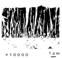
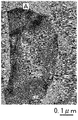
- FIG. 1A It is a drawing substitute photograph (magnification of 10,000 times) of the scanning electron microscope (SEM) image which shows the cross section of the rake surface of the coated cutting tool of Example 1.
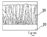
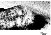
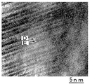
- FIG. 1A It is a schematic model line with respect to the drawing substitute photograph of FIG. 1A. It is a drawing substitute photograph which binarized the drawing substitute photograph of FIG. 1A. It is a drawing substitute photograph (magnification 200,000 times) of the image of the transmission electron microscope (TEM) of the hard film of Example 1.
- TEM transmission electron microscope
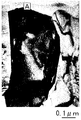
- FIG. 2A It is a schematic model line with respect to the drawing substitute photograph of FIG. 2A. It is a drawing substitute photograph which binarized the drawing substitute photograph of FIG. 2A. It is a drawing substitute photograph (magnification 2,000,000 times) of the TEM image which expanded the A section of FIG.
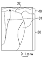
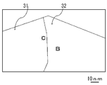
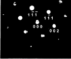
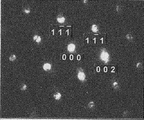
- FIG. 3A It is a schematic diagram line with respect to the drawing substitute photograph of FIG. 3A. It is a drawing substitute photograph which binarized the drawing substitute photograph of FIG. 3A. It is a drawing substitute photograph which shows the nanobeam diffraction pattern in B part of the drawing substitute photograph of FIG. 3A. It is a drawing substitute photograph which binarized the drawing substitute photograph of FIG. 4A. It is a drawing substitute photograph (magnification 4,000,000 times) of the TEM image which expanded the C section of the drawing substitute photograph of FIG. 3A. It is a schematic model line with respect to the drawing substitute photograph of FIG. 5A. It is a drawing substitute photograph which binarized the drawing substitute photograph of FIG. 5A.
- FIG. 2 is a view showing the X-ray diffraction measurement results of Example 1; It is a schematic diagram of the chemical vapor deposition apparatus (CVD furnace) used for coating of the hard film of an example.
- CVD furnace chemical vapor deposition apparatus
- FIG. 5 is a schematic view of a chemical vapor deposition apparatus (CVD furnace) used for coating the hard film of Comparative Example 2; It is a schematic sectional drawing of the gas jet nozzle of the chemical vapor deposition apparatus (CVD furnace) used for coating of the hard film of the comparative example 2.
- FIG. It is a schematic diagram of the chemical vapor deposition apparatus (CVD furnace) used for coating of the hard film of Comparative Examples 3 and 4. It is a schematic sectional drawing of the gas jet nozzle of the chemical vapor deposition apparatus (CVD furnace) used for coating of the hard film of Comparative Examples 3 and 4.
- the inventors have found that, for nitrides mainly composed of Al and Cr, by controlling the orientation of the (311) plane, the durability is improved when used as a coating film of a coated cutting tool,
- the present invention has been reached. That is, for nitrides mainly composed of Al and Cr, the X-ray diffraction intensity of each crystal plane is determined, and the X-ray diffraction intensity of the (311) plane is arranged by paying attention to the X-ray diffraction intensity of the (311) plane. It has been surprisingly found that the durability of the coated cutting tool is improved when there is a fixed relationship to the diffraction intensity of the other surface.
- the NH 3 gas is an alkaline gas, in order not to overreact and CrCl 3 gas and AlCl 3 gas is a halogen gas, the total amount of the NH 3 gas of N 2 gas and H 2 gas in the mixed gas It has also been found that it is necessary to make the ratio to be specific, and that the Cr chloride gas needs to be generated in a CVD furnace.
- composition of a hard film which constitutes a coated cutting tool of one embodiment of the present invention the composition, the crystal structure, the characteristic, and the details of the manufacturing method and the manufacturing apparatus are explained.
- the hard film according to the present embodiment is a nitride based on Al and Cr.
- the film containing nitride of Al and Cr is a film excellent in wear resistance and heat resistance.
- the hard film according to the present embodiment has an Al content of 60 atomic% with respect to the total amount of metal elements including metalloids (hereinafter referred to as metal elements). And above. Furthermore, it is preferable to make the content ratio of Al 70 atomic% or more. However, when the content ratio of Al is too high, AlN of a fragile hcp (hexagon close-packed) structure is increased, and the durability of the coated cutting tool is reduced. Therefore, the content ratio of Al is preferably 90 atomic% or less.
- the content ratio of Cr is 10 atomic% or more. Furthermore, the content ratio of Cr is preferably 15 atomic% or more. However, if the content ratio of Cr is too high, the content ratio of Al relatively decreases and the heat resistance decreases. Therefore, the content ratio of Cr is preferably 30 atomic% or less.
- the total content ratio of Al and Cr is set to 90 atomic% or more in order to impart high heat resistance to the hard coating. Furthermore, the total content ratio of Al and Cr is preferably 95 atomic% or more.
- the hard film according to the present embodiment may contain metal elements other than Al and Cr. For example, Ti, Si, Zr, B, and V may be contained. These elements are elements generally added to AlTi-based nitrides and AlCr-based nitrides, and a small amount of addition does not significantly reduce the durability of the coated cutting tool.
- the hard film according to the present embodiment may be a nitride of Al and Cr.
- the hard film according to the present embodiment may contain 1 mass% or less of the components contained in the film forming gas such as oxygen, carbon and chlorine as unavoidable impurities, when the entire hard film is 100% by mass. If the hard film according to the present embodiment is a nitride as a whole, it may partially contain oxides, composite carbides and composite carbonitrides based on Al and Cr, and the like due to these impurities. .
- ⁇ Crystal structure> In the hard coating according to the present embodiment, one of X-ray peak intensities (peak intensities) attributed to the fcc (face-centered cubic lattice) structure in X-ray diffraction shows the maximum intensity, and the fcc structure is the main.
- the hard film based on the hcp structure and the hard film of amorphous are low in hardness and weak, and the durability of the coated cutting tool is significantly reduced.
- the peak strength attributable to the fcc structure shows the maximum strength, the hardness and the toughness of the hard film are increased, and the durability of the coated cutting tool is improved.
- the hard film according to the present embodiment preferably has a single structure of fcc structure, but if any of the peak intensities resulting from the fcc structure show the maximum strength, it partially contains the hcp structure It is also good.
- the hard coating may not have a high hardness, and may have an hcp structure.
- the content ratio of the hcp structure is too high, the durability of the coated cutting tool is reduced. Therefore, even when the hcp structure is contained, it is preferable to set the maximum peak intensity caused by the hcp structure to 1/10 or less of the maximum peak intensity caused by the fcc structure.
- the hard film according to the present embodiment has (111) surface, (200) surface, (220) surface, (311) surface, (222) surface, (400) surface, (331) of fcc structure in X-ray diffraction. It has peak intensity in at least 9 planes of planes, (420) plane and (422) plane. The inventors have found that fine columnar particles increase as the X-ray diffraction intensity ratio attributed to the (311) plane increases.
- the X-ray diffraction intensity ratio TC (311) described below is set to 1.30 or more for the X-ray diffraction intensity ratio attributed to the (311) plane. Then, the X-ray diffraction intensity ratio TC (311) attributed to the (311) plane is the above-mentioned other plane (the standard X-ray diffraction intensity of aluminum nitride has no (422) plane, so Further, by increasing the X-ray diffraction intensity ratio of the eight surfaces excluding the above, the film structure becomes finer, the plastic deformation of the hard film is suppressed, and the film wear is easily suppressed, which is also preferable. I found out.
- the X-ray diffraction intensity ratio TC (hkl) represented by the following equation (Equation 1) is determined for the X-ray diffraction intensity ratio TC (hkl) of each plane including the (311) plane.
- the intensity ratio TC (311) is evaluated.
- TC (hk1) ⁇ I (hk1) / IO (hk1) ⁇ / [[ ⁇ I (hk1) / IO (hk1) ⁇ / 8]
- I o (hkl) Standard X-ray diffraction intensity of (hkl) plane of aluminum nitride described in ICDD (International Center for Dffraction Data) file number 00-025- 1495.
- ⁇ means the sum of the following eight planes.
- (Hkl) (111) plane, (200) plane, (220) plane, (311) plane, (222) plane, (400) plane, (331) plane and (420) plane.
- the aluminum nitride standard X-ray diffraction intensity similar to the X-ray diffraction of aluminum chromium nitride is used.
- the fcc structure aluminum nitride has the (420) plane: It can be confirmed that the X-ray diffraction intensity of is high. Further, since the standard X-ray diffraction intensity of the aluminum nitride does not have the (422) plane, the X diffraction intensity ratio TC (hkl) is obtained from the above-described eight planes.
- the durability of the coated cutting tool can be improved by using nitrides mainly composed of Al and Cr in which the value of the X-ray diffraction intensity ratio TC (311) is 1.30 or more. It can be enhanced. Further, the X-ray diffraction intensity ratio TC (311) is more preferably 1.80 or more. More preferably, the X-ray diffraction intensity ratio TC (311) is 2.00 or more.
- the upper limit value of the X-ray diffraction intensity ratio TC (311) is not particularly limited, but when the nitride is produced by the method disclosed in this specification, it is estimated that about 6.00 is the upper limit value, and the upper limit value. Is more preferably 5.00. Furthermore, it is even more preferable that the X-ray diffraction intensity ratio TC (311) is larger than the X-ray diffraction intensity ratio TC (hkl) of other crystal planes.
- the values of the X-ray diffraction intensity ratio TC (420) and the X-ray diffraction intensity ratio TC (200) are preferably 1.00 or less.
- the reason is that the value of the X-ray diffraction intensity ratio TC (hkl) of the (420) plane and the (200) plane at which the peak intensity is high in the standard X-ray diffraction intensity becomes smaller, the X-ray diffraction intensity ratio TC (311) The value of is likely to be high, which is preferable. More preferably, the values of the X-ray diffraction intensity ratio TC (420) and the X-ray diffraction intensity ratio TC (200) are 0.50 or less.
- the X-ray diffraction peak of the aluminum chromium nitride hard coating is similar to the X-ray diffraction peak of the titanium aluminum nitride hard coating, and the peak positions overlap. Therefore, when laminating the hard film and the titanium aluminum nitride hard film according to the present invention, for example, alternately laminating the X-ray diffraction peak obtained as a peak of the aluminum chromium nitride hard film, X-ray analysis intensity ratio TC (hkl) It is sufficient to calculate
- the hard film according to the present embodiment has a total peak intensity of the fcc structure (a sum of the sum of the peak intensities of the eight planes plus the X-ray peak intensity of the (422) plane) in X-ray diffraction as the TA
- the value of TB / TA is 0.05 or more when the peak intensity resulting from (422) plane is TB.
- the peak intensity on the high angle side such as the (422) plane becomes relatively weak, but the peak intensity on the (422) plane becomes stronger, resulting in a hard film with higher crystallinity and durability of the coated cutting tool Improve.
- the value of TB / TA to 0.07 or more, the durability tends to be more excellent, which is preferable.
- (422) plane peak intensity can be confirmed in the X-ray diffraction diagram by calculating the interplanar spacing d value. .
- the hard film according to the present embodiment is composed of a collection (columnar structure) of columnar particles grown in the film thickness direction on the surface of the base material.
- the durability of the coated cutting tool is improved because the hard film made of nitride based on Al and Cr becomes columnar particles grown in the film thickness direction with respect to the surface of the substrate.
- variety in the surface side of the said columnar particle is 0.1 micrometer or more and 2.0 micrometers or less.
- the average width on the surface side is 0.1 ⁇ m or more, the durability of the coated cutting tool is further enhanced.
- the average width on the surface side is set to 2.0 ⁇ m or less, plastic deformation of the hard coating is difficult to occur, and the particle diameter of the hard coating coming off from the hard coating is reduced, so that tool wear is easily suppressed.
- the surface side in the present embodiment refers to the vicinity of the surface of the hard film on the side in contact with the work material, for example, the vicinity of a CP (Cross-section Polisher) processed surface.
- the width of the columnar particles of the hard coating can be measured from cross-sectional observation with a transmission electron microscope or a scanning electron microscope. The measurement point was at a position 0.5 ⁇ m deep from the surface of the film on the side in contact with the work material. If the width of continuous 30 or more columnar particles is observed, the average value of the particle widths converges. Therefore, what is necessary is just to obtain
- the microstructure of the hard film according to the present embodiment is not particularly limited. That is, it may have crystal particles having only a single layer structure. Moreover, you may have the crystal grain which consists only of laminated structure. It may have crystal grains consisting only of a single layer structure, crystal grains consisting only of a laminated structure, and crystal grains consisting of a single layer structure and a laminated structure. In particular, it is preferable that crystal particles in which a single layer structure and a laminated structure coexist are dispersed in one particle.
- the content ratio of Al is relatively high
- the nitride of Al and Cr is relatively high
- the content ratio of Al is relatively high.
- the crystal grains are dispersed in the microstructure with a portion consisting of a laminated structure in which Al and Cr nitrides are alternately laminated and a portion consisting of a single layer structure of Al and Cr nitride having a high Al content ratio
- the portion of the single layer structure is estimated to be less distorted because the crystallinity is relatively higher than that of the portion of the laminated structure. Therefore, the durability of the coated cutting tool is improved by the crystal particles having a single layer structure.
- the portion composed of the laminated structure has a relatively small content ratio of Al as compared with the portion composed of the single layer structure, so the content of Al as the whole of the crystal grain increases too much, and the fragile hcp structured AlN increases. Is suppressed. And, by the presence of such particles in the microstructure, the wear resistance and heat resistance of the hard coating as a whole can be enhanced and the excellent durability can be exhibited.
- the content ratio of Al is 60 atomic% or more, and the content ratio of Al is preferably 60 atomic% or more, and the content ratio of Al is relatively high.
- the nitride of Al and Cr having a low content of Al preferably has an Al content of 55 atomic% or less.
- the nitride of Al and Cr which has a relatively high Al content, preferably has an Al content of 70 at% or more, and more preferably 80 at% or more. Is preferred. However, when the content ratio of Al is too high, AlN of the hcp structure is increased, so the content ratio of Al is preferably 95 atomic% or less. Furthermore, it is more preferable that it is 90 atomic% or less.
- the nitride of Al and Cr having a relatively low content ratio of Al preferably has a content ratio of Al of 50 atomic% or less, and further, 40 atomic% or less. Is preferred. However, if the content ratio of Al is too low, the heat resistance is lowered in the entire hard coating, so the content ratio of Al is preferably 10 atomic% or more. Furthermore, 20 atomic% or more is more preferable.
- the content ratio of Al is preferably 60 atomic% or more. Furthermore, the content ratio of Al is preferably 70 atomic% or more. However, if the content ratio of Al is too high, AlN of the hcp structure is increased, and therefore it is more preferable that the content ratio of Al in the portion of the single layer structure of the crystal particle is 90 atomic% or less.
- the microstructure of the hard film according to the present embodiment may be composed of crystal particles having only a laminated structure or a single layer structure.
- the average film thickness of the hard film according to the present embodiment is preferably 1.0 ⁇ m or more and 15.0 ⁇ m or less. The reason is that if the film thickness is less than 1.0 ⁇ m, a sufficient tool life can not be provided because the film thickness is thin. On the other hand, if the film thickness exceeds 15.0 ⁇ m, the film may be too thick and cutting accuracy may be degraded. It is.
- the lower limit of the film thickness is more preferably 2.0 ⁇ m, still more preferably 3.0 ⁇ m, and still more preferably 5.0 ⁇ m.
- the upper limit of the film thickness is more preferably 12.0 ⁇ m, and still more preferably 10.0 ⁇ m.
- ⁇ Intermediate film and upper layer> In the coated cutting tool of the present embodiment, in order to improve the adhesion between the hard coating and the base, if necessary, between the base of the tool and the hard coating, for example, nitride, carbonitride, An intermediate film made of any of carbides may be provided.
- the intermediate film is preferably a nitride of Al and Ti, a nitride of Ti, or a carbonitride, which is excellent in adhesion to the substrate and the hard film.
- a compound when not represented by a chemical formula such as a nitride of Al and Ti, a nitride of Ti, or a carbonitride, it is not necessarily limited to the one in the stoichiometric range.
- an upper layer having a component ratio or a composition different from that of the hard coating according to the present embodiment may be provided on the hard coating according to the present embodiment.
- the upper layer may be, for example, an oxide such as nitride, carbonitride, carbide or alumina, and may be provided through the bonding layer.
- alumina generally used as a coating layer formed by chemical vapor deposition is preferable because it improves the heat resistance of the coated cutting tool.
- coated cutting tools provided with alumina are generally used in cutting of castings. Also in the coated cutting tool of the present invention, it is preferable to provide alumina as an upper layer as needed, because the durability is further improved.
- Al and Ti nitrides, Al and Cr nitrides having a relatively high Al content ratio, and Al and Cr nitrides having a relatively low Al content ratio are alternately stacked as the upper layer. You may provide the laminated film which carried out.
- the hard coating according to the present embodiment is formed by chemical vapor deposition and has a tensile stress, it is preferable to perform a cutting edge treatment after coating, which causes stress release by a blast device or the like after coating. By performing the cutting edge treatment after this coating, the chipping resistance is improved, and a hard coating having excellent tool life is obtained.
- mixed gas A and mixed gas B described below are separately introduced into a chemical vapor deposition apparatus (CVD furnace) whose internal temperature is raised to 750 ° C. or more described later, By mixing in the device, it is possible to coat a tool substrate such as an insert substrate previously mounted in the device.
- CVD furnace chemical vapor deposition apparatus
- a base material is a well-known thing as this kind of base material, it can be used.
- cemented carbide for example, WC base cemented carbide, containing Co in addition to WC, and further containing carbides of Ti, Ta, Nb and the like are added
- cermet TiC, TiN, TiCN etc.
- cBN etc. can be illustrated.
- the tool base is not limited to the insert base material, and examples thereof include a base material such as a drill, an indexable cutting insert for drill, an indexable cutting insert for milling, a metal saw, a reamer, a tap and the like.
- the mixed gas A includes the mixed gas a1 and the mixed gas a2.
- the mixed gas a1 includes HCl gas and H 2 gas (also referred to as “mixed gas for producing Cr chloride” or “mixed gas for obtaining mixed gas a1”), and the two gases are in contact with metal Cr And a gas containing Cr chloride gas (which is not only a component that can be expressed by CrCl 3 but also a chemical combination of Cr and Cl), and a typical composition is Cr / H 2 chloride in volume ratio It is not less than 0.008 and not more than 0.140.
- the volume percent of Cr chloride gas and the volume percent of AlCl 3 gas were estimated from the amount of HCl gas introduced to generate these gases, as described later.
- the mixed gas a1 HCl gas and H 2 gas for producing Cr chloride gas are heated and brought into contact with metal Cr, and this heating is performed inside the CVD furnace as described later in the description of the manufacturing apparatus. It is preferable to carry out in the gas preheating part. Further, it is preferable to obtain the mixed gas A by mixing the mixed gas a2 heated to near the temperature of the mixed gas a1 with the mixed gas a1 which has a Cr chloride gas. By doing so, generation of Cr chloride gas can be facilitated without the influence of AlCl 3 gas.
- the temperature at which Cr chloride gas is generated in the gas preheating unit is a temperature at which about 750 ° C., which is the lowest set temperature in the furnace, is generated stably. The reason is that if this temperature is too low, the amount of Cr chloride gas generated decreases, the entire hard coating becomes Al-rich, and it becomes easy to increase the hcp structure AlN.
- the AlCl 3 gas contained in the mixed gas a2 may be generated by, for example, introducing a mixed gas of H 2 gas and HCl gas into an AlCl 3 gas generator filled with metal Al and kept at 330 ° C. It is preheated when mixed with the mixed gas a1 to form the mixed gas A. It is preferable that the temperature of the mixed gas a2 is not so different from the temperature of the mixed gas a1 because the hard coating has a structure formed of an aggregate of columnar particles, and the temperature is near the temperature of the mixed gas a1 (for example, ⁇ 80 ° C) is good.
- the mixed gas A obtained by mixing the mixed gas a2 with the mixed gas a1 it is preferable to maximize the flow rate of the H 2 gas.
- the mixed gas a1 and the mixed gas a2 may contain N 2 gas or Ar gas.
- the mixed gas B contains H 2 gas, N 2 gas and NH 3 gas.
- the composition ratio of b 2 / b 1 is 0.002 or more and 0.020 or less It is preferable to obtain the composition of the hard film according to the present embodiment. If the composition ratio of the mixed gas B is in the range of this composition ratio, excessive reaction between the NH 3 gas as the alkali gas and the CrCl 3 gas or the AlCl 3 gas as the halogen gas is easily suppressed.
- the mixed gas B is also preheated, but the temperature rise due to the preheating is suppressed, and preheating is performed lower than the temperature of the mixed gas A to avoid excessive preheating.
- the mixed gas B is prevented from being excessively preheated like the mixed gas A.
- the reaction rate between NH 3 contained in the mixed gas B and Cr chloride gas and AlCl 3 gas contained in the mixed gas A is suppressed, and the hard film becomes a structure composed of a collection of columnar particles.
- the gas flow path of the mixed gas B passes through the gas preheating section, but as described above, the preheating temperature is suppressed and excessive preheating is avoided.
- the flow path of the gas a2 and the gas flow path of the mixed gas B are sequentially brought close in this order, and the total of the length of the gas flow path of the mixed gas a1 and the length of the gas flow path of the mixed gas a2 is more than the gas flow path of the mixed gas B It is also conceivable to make the length longer by 3 times or more, preferably 5 times or more and 8 times or less.
- the flow path of the mixed gas B is preferably 650 mm or less, and more preferably 550 mm or less. As a result, excessive reaction between NH 3 gas and AlCl 3 gas or Cr chloride gas is suppressed, and the hard film becomes a structure composed of a collection of columnar particles.
- the gas flow path of the mixed gas for obtaining the mixed gas a1, the gas flow path of the mixed gas a2, and the gas flow path of the mixed gas B are each from the time when each mixed gas is introduced into the furnace to the end of the preheating.
- Flow channel That is, as described later, as in the preheating part of the CVD furnace used in the present embodiment, it refers to a connection flow path with rotation during film formation and a flow path in the preheating chamber (preheating chamber).
- the mixed gas A and the mixed gas B are not mixed before being introduced into the CVD furnace (in the reaction vessel), and the nozzle holes of the mixed gas A and the nozzle holes of the mixed gas B are separately provided to Independently introduce (in the reaction vessel).
- the nozzle hole of the mixed gas B changes the ejection direction from the nozzle hole of the mixed gas A, and the rotation axis is more than the nozzle hole of the mixed gas A.
- the reaction distance between NH 3 gas and AlCl 3 gas or Cr chloride gas is prevented from becoming too fast, for example, by arranging the distance from the outside.
- the reaction pressure for film formation is preferably 3 kPa or more and 5 kPa or less. The reason is that when the reaction pressure is too low, the deposition rate decreases, while when the reaction pressure is too high, the reaction is promoted and it is difficult to obtain a structure composed of a collection of columnar particles. .
- the temperature in the CVD furnace (in the reaction vessel) is preferably 750 ° C. or more and 850 ° C. or less. The reason is that if the film forming temperature is too low, the amount of chlorine in the hard film increases and the wear resistance decreases, while if the film forming temperature is too high, the above reaction is promoted, and it is composed of a collection of columnar particles. Tissue is difficult to obtain.
- the furnace temperature is more preferably 770 ° C. or more and 820 ° C. or less.
- the chemical vapor deposition apparatus (CVD furnace) used in one embodiment of the present invention has a temperature in the furnace (in the reaction vessel) of 750 ° C. or more and 850 ° C. or less in the furnace (in the reaction vessel) in order to carry out the manufacturing method described above.
- the pressure can be 3 kPa or more and 5 kPa or less, and has the following characteristic configuration. The specific configuration will be described in an embodiment to be described later, and here, the description will be made focusing on the items to be provided as an apparatus.
- the coating apparatus preheats independently each of three types of mixed gas of mixed gas and mixed gas a2 for generating Cr chloride gas which is a component of mixed gas A and mixed gas B, and the inside of the CVD furnace (reaction (Inside the container).
- the CVD furnace has a gas preheating unit and a gas releasing unit for introducing a gas into a reaction container described later.
- the gas preheater is (1) A Cr chloride gas generation unit for generating a mixed gas a1 containing Cr chloride gas by bringing a mixed gas for generating Cr chloride gas into contact with metal Cr, (2) a first preheating unit for preheating the mixed gas a2, (3) a second preheating unit for preheating the mixed gas B, and (4) A mixing unit which mixes the mixed gas a1 and the mixed gas a2 to form a mixed gas A, And.
- the heat source of the preheating unit may be provided independently for the preheating unit, or a heat source (heater) provided in the CVD furnace may be used. Further, the metal Cr is in the form of flakes or the like in which Cr chloride gas is easily generated.
- the mixed gas a1 is added to the heater of the CVD furnace which is the preheating source.
- a flow path for generating the mixed gas a1 as an example by devising the arrangement of the gas flow path while closely approaching in order of the gas flow path to be generated, the gas flow path of the mixed gas a2, and the gas flow path of the mixed gas B
- the total length of the length of the mixed gas a2 and the length of the flow path of the mixed gas a2 is 3 times or more, preferably 5 times or more and 8 times or less of the length of the flow path of the mixed gas B.
- the length of the flow path of the gas that produces the mixed gas a1 the length of the flow path of the mixed gas a2, and the length of the flow path of the mixed gas B are respectively from the gas inlet of the CVD furnace It says the length to the exit. That is, as described later, as in the preheating unit of the CVD furnace used in the present embodiment, it refers to a connection passage accompanied by rotation during film formation and a passage in the preheating chamber (preheating chamber).
- the mixed gas a1 is preheated to 750 ° C. or higher, while the mixed gas a2 is preheated to a temperature near the mixed gas a1, for example, in the range of ⁇ 80 ° C. It can be mixed to make a mixed gas A.
- the mixed gas B has a temperature lower than that of the mixed gas A (TeA> TeB).
- the mixed gas B since the gas flow path in the preheating section is shortened, it can be said that the temperature rise is suppressed.
- the inside of the CVD furnace was provided with a first pipe provided with a nozzle hole for introducing the mixed gas A into the reaction vessel as a gas discharge part, and a nozzle hole for introducing the mixed gas B into the reaction vessel It has a second pipe.
- two second pipes are disposed to face the outside of one first pipe, and these pipes are arranged at a speed of 2 to 5 revolutions / minute around the axis of the first pipe. It is preferable to rotate.
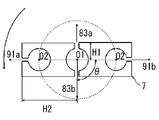
- the distance from the nozzle hole of the mixed gas A to the rotation axis (axial center of the first pipe) is H1
- the nozzle hole of the mixed gas B and the rotation axis (first pipe) is H1
- the lower limit of H 2 / H 1 is preferably 1.5
- the upper limit is preferably 4 and more preferably 3, where H 2 is the distance from the axis of
- the gas ejection direction from the nozzle hole of the mixed gas A and the gas ejection direction from the nozzle hole of the mixed gas B be arranged to deviate from 30 degrees to 90 degrees.
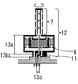
- a chemical vapor deposition apparatus (CVD furnace) 1 shown in FIGS. 9A, 9B and 9C is used as a schematic view. The outline of this device will be described.
- the CVD furnace 1 has a cylindrical chamber 2, a heater 3 provided inside the peripheral wall of the chamber 2, and a plurality of insert mounting plates 4 for mounting a large number of insert substrates (tool substrates) 20 in the chamber 2. It has a reaction vessel 5, a connection channel 11 provided at the lower part of the reaction vessel 5, and a preheating chamber 6 which is a preheating unit.
- the preheating chamber 6 is A mixed gas for Cr chloride gas generation introduced from the gas flow passage 82 is dispersed in the radial direction of the preheating chamber 6 via the connection flow passage 11 in a cylindrical shape and the lower portion thereof to generate a Cr chloride gas generation chamber 62 Space to introduce The Cr chloride gas generation chamber 62 is provided immediately above this space, has a cylindrical space whose center is cylindrical with the outer periphery of the cylinder matching the outer periphery of the preheating chamber 6, and concentric with the preheating chamber 6, A preheating chamber 61 (first preheating unit) which is formed concentrically with the preheating chamber 6 in a cylindrical space at the center of the Cr chloride gas generation chamber 62 and preheats the mixed gas a2 introduced from the gas flow passage 81; A mixing chamber 63 (mixing unit) located above the Cr chloride gas generation chamber 62 and the preheating chamber 61 and mixing a mixed gas a1 and a mixed gas a2 described later to form a mixed gas A;
- the preheating chamber 6 ie, at the axial center of the preheating chamber 61, there is a flow passage (second preheating portion) through which the mixed gas B introduced from the gas flow passage 91 penetrates in the height direction.
- the passage is connected to the outer passage of the pipe 7 at the top of the preheating chamber 6, which has the shortest length (550 mm) passing through the preheating unit.
- the flow path of the mixed gas A mixed in the mixing chamber 63 is provided to be connected to the central flow path 2 of the pipe 7 at the upper part of the preheating chamber 6.
- the mixed gas introduced from the gas flow channel 82 is introduced into the Cr chloride gas generator 62 in the preheating chamber 6 and reaches the temperature in the furnace at 750 ° C. or higher to react with the metal Cr in the same generation chamber to generate Cr chloride
- the mixed gas a 1 containing gas is introduced into the mixing chamber 63.
- mixed gas B is introduce
- the reaction gas A introduced from the gas flow paths 81 and 82 and penetrating the preheating chamber 61 is introduced into the central flow path of the pipe 7 and is introduced into the reaction vessel 5 from the nozzle holes 83a and 83b.
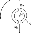
- the positional relationship between the nozzle holes 83a, 83b and the nozzle holes 91a, 91b is as shown in the gas jet nozzle cross-sectional view of FIG. 9C, the nozzle holes 91a, 91b have the rotational axis of the pipe 7 more than the nozzle holes 83a, 83b.
- H2 / H1 is 2 when the distance from the nozzle holes 91a and 91b to the rotation axis O1 is H2 and the distance from the nozzle holes 83a and 83b to the rotation axis O1 is H1.
- the jet direction of the nozzle holes 91a and 91b and the jet direction of the nozzle holes 83a and 83b form an angle of 90 degrees.
- connection channel 11, the preheating chamber 6 and the pipe 7 shown at 12 in FIG. 9B are configured to rotate at a speed of 2 rotations / minute, but in FIGS. 9A, 9B and 9C, this rotation is The illustration of the necessary configuration is omitted.
- the total length of the length of the gas flow path for obtaining the mixed gas a1 and the length of the gas flow path for the mixed gas a2 is the same as FIG. 9B.
- the length of the gas flow path of the mixed gas B which is the sum of 13a, 13b and 13c, is approximately four times the length of the gas flow path.
- Base material Milling insert (WDNW14520 made by Mitsubishi Hitachi Tool) made of WC base cemented carbide (10% by mass Co, 0.6% by mass Cr 3 C 2 , balance WC and unavoidable impurities) as a base material WC base cemented carbide (7% by mass Co, 0.6% by mass Cr 3 C 2 , 2.2% by mass ZrC, 3.3% by mass TaC, 0.2% by mass NbC, balance WC And an insert for evaluation of physical properties (made of ISO standard SNMN 120408).
- WDNW14520 made by Mitsubishi Hitachi Tool
- a titanium nitride film was formed as an intermediate film.
- the substrate was set in the CVD furnace 1 shown in FIG. 9A, and the temperature in the CVD furnace 1 was raised to 800 ° C. while flowing H 2 gas. Thereafter, 83.1% by volume of H 2 gas, 15.0% by volume of N 2 gas, 1.9% by volume of TiCl at 800 ° C.
- a mixed gas consisting of four gases was introduced into the preheating chamber 62, and flowed into the reaction vessel 5 at a flow rate of 67 L / min from the first nozzle holes 83a and 83b of the pipe 7 to form a titanium nitride film.
- Example 6 a titanium aluminum nitride film was formed as an intermediate film.
- the substrate was set in the CVD furnace 1 shown in FIG. 9A, and the temperature in the CVD furnace 1 was raised to 800 ° C. while flowing H 2 gas. Thereafter, at 800 ° C. and 4 kPa, gas volume of 81% by volume of TiCl 4 gas, 0.45% by volume of AlCl 3 gas, 7.50% by volume of N is introduced from the gas inlet of the preheating chamber 6 through the gas passage 81.
- a mixed gas consisting of 2 gas and 52.51% by volume of H 2 gas is introduced into the preheating chamber 62 and flows from the first nozzle holes 83 a and 83 b of the pipe 7 into the reaction vessel furnace 5 and the gas flow path 91
- a mixed gas consisting of 30.76% by volume of H 2 gas, 7.50% by volume of N 2 gas, 1.13% by volume of NH 3 gas is introduced into the second nozzle holes 91 a and 91 b of the pipe 7. It flowed into the reaction vessel 5 at a flow rate of 67 L / min to form a titanium aluminum nitride film.
- the coating conditions of the intermediate film are shown in Table 1.
- Step of obtaining mixed gas a1 After reducing the pressure in the CVD furnace 1 to 4kPa while introducing H 2 gas, the gas flow path 82 of the preheating chamber 6 shown in FIG. 9A, and a mixed gas of H 2 gas and HCl gas was kept to 400 ° C. .
- the Cr chloride gas generation chamber 62 of the preheating chamber 6 preheated to 800 ° C. is filled with Cr metal flakes (purity 99.99%, size 2 mm to 8 mm), and H 2 gas and HCl introduced from the gas flow path 82 A mixed gas of H 2 gas and a Cr chloride gas was generated to react with the mixed gas of gases, and a mixed gas a 1 was generated and introduced into the mixing chamber 63.
- a mixed gas a2 obtained by mixing H 2 gas and AlCl 3 gas was introduced into the preheating chamber 62 and preheated from the gas inlet of the preheating chamber 6 through the gas flow path 81. Then, the mixed gas a1 and the mixed gas a2 are mixed in the mixing chamber 63 to obtain the mixed gas A having a temperature near 800 ° C., which is the temperature of the preheating chamber. Then, the obtained mixed gas A was introduced from the first nozzle holes 83 a and 83 b of the pipe 7 into the reaction vessel furnace. The total flow rate of the mixed gas A was 48.75 L / min.
- a mixed gas B composed of H 2 gas, N 2 gas and NH 3 gas was introduced into the gas flow path 91 and introduced into the furnace from the second nozzle holes 91 a and 91 b of the pipe 7.
- the total flow rate of the mixed gas B was 30.25 L / min.
- Examples 1 to 8 and Comparative Example 1 were formed on the intermediate coatings described in Table 1 by the chemical vapor deposition method with each mixed gas composition shown in Table 2 to form nitrides of Al and Cr with a thickness of about 6 ⁇ m.
- the object was coated to produce a coated cutting tool.
- Comparative Example 1 does not satisfy the mixed gas composition defined in the embodiment of the present invention.
- the amount of generated Cr chloride gas and AlCl 3 gas was determined using the amount of HCl gas introduced into the Cr chloride gas generation chamber as the amount of Cr chloride gas to determine the composition of the mixed gas.
- the comparative example 2 produced the hard film using the CVD furnace shown to FIG. 10A and FIG. 10B.
- the configuration of this CVD furnace will be briefly described.
- 10A and 10B members denoted by the same reference numerals as those in FIGS. 9A and 9C represent the same members as those in these figures.
- the mixed gas is introduced from the gas flow passage 92, and the mixed gas is introduced into the reaction vessel 5 from the nozzle hole 92 a provided in the pipe 7.
- illustration of the structure required for rotation is abbreviate
- a titanium nitride film which is an intermediate film, was formed on the substrate under the same film forming conditions as in Example 1 as in the above example. Thereafter, the pressure in the CVD furnace 1 is lowered to 1 kPa while flowing H 2 gas at 800 ° C., and then H 2 gas, N 2 gas, CrCl 3 gas and AlCl 3 of the composition shown in Table 2 A mixed gas of gas and NH 3 gas was introduced into the reaction vessel 5 from the nozzle hole 92 a of the pipe 7. Thus, a coating of Al and Cr nitride having a thickness of about 6 ⁇ m was coated on the intermediate coating by chemical vapor deposition to produce a coated cutting tool.
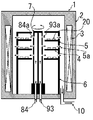
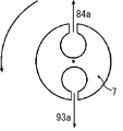
- the comparative example 3 produced the hard film using the CVD furnace shown to FIG. 11A and FIG. 11B.
- the configuration of this CVD furnace will be briefly described.
- 11A and 11B members denoted by the same reference numerals as those in FIGS. 9A and 9C represent the same members as those in these figures.
- the mixed gas introduced from the gas flow passage 84 is independent from the nozzle hole 94 a provided in the nozzle 7
- the mixed gas introduced from the gas passage 93 is independent from the nozzle hole 94 a provided in the nozzle 7.
- the pipe 7 rotates, illustration of the structure required for rotation is abbreviate
- a titanium nitride film which is an intermediate film, was formed on the substrate under the same film forming conditions as in Example 1 as in the above example. Thereafter, the pressure in the CVD furnace 1 is lowered to 4 kPa while flowing H 2 gas at 800 ° C., and then H 2 gas, N 2 gas, CrCl 3 gas and AlCl 3 of the composition shown in Table 2 A mixed gas A of gas is introduced into the reaction vessel 5 through the nozzle hole 84 a of the pipe 7, and a mixed gas composed of H 2 gas, N 2 gas and NH 3 gas in the gas flow path 93 of the composition shown in Table 2 B was introduced and introduced into the reaction vessel 5 from the nozzle hole 93 a of the pipe 7. Thus, a coating of Al and Cr nitride having a thickness of about 6 ⁇ m was coated on the intermediate coating by chemical vapor deposition to produce a coated cutting tool.
- the comparative example 4 produced the hard film using the same CVD furnace as the comparative example 3.
- the pressure in the CVD furnace 1 is lowered to 4 kPa while flowing H 2 gas at 800 ° C., and then H 2 gas, N 2 gas, CrCl 3 gas, and AlCl 3 having the composition shown in Table 2
- a mixed gas A of gas is introduced into the furnace through the nozzle hole 84a of the pipe 7 and mixed gas B consisting of H 2 gas, N 2 gas and NH 3 gas having the composition shown in Table 2 in the gas flow path 93
- mixed gas B consisting of H 2 gas, N 2 gas and NH 3 gas having the composition shown in Table 2 in the gas flow path 93
- a coating of Al and Cr nitride having a thickness of about 6 ⁇ m was coated on the intermediate coating by chemical vapor deposition to produce a coated
- Example 8 an upper layer was provided.
- the nitride film mainly composed of Al and Cr according to the present embodiment is formed, and then the bonding layer and the aluminum oxide layer are formed in this order.
- a bonding layer consisting of a Ti (CN) layer and a Ti (CNO) layer
- 63.5 volumes are obtained at 1000 ° C. and 16 kPa from the gas inlet of the preheating chamber 6 through the gas channel 81.
- a mixed gas consisting of 1% H 2 gas, 22.0% by volume N 2 gas, 3.2% by volume CH 4 gas, and 1.3% by volume TiCl 4 gas is introduced into the preheating chamber 62, the pipe 7
- the 10% by volume of H 2 gas is introduced into the gas flow path 91 while flowing from the first nozzle holes 83a and 83b into the reaction vessel furnace, and the second nozzle holes 91a and 91b of the pipe 7 enter the furnace.
- a 0.5 ⁇ m thick Ti (CN) layer was formed. 51.3% by volume of H 2 gas, 30.7% by volume of N 2 gas, 3.0% by volume of CH 4 gas, 1.2% by volume of TiCl 4 gas, continuously at 1000 ° C. and 16 kPa
- a mixed gas consisting of 0 volume% CO gas and 0.8 volume% CO 2 gas is introduced into the preheating chamber 62 and is flowed from the first nozzle holes 83 a and 83 b of the pipe 7 into the reaction vessel furnace, 10% by volume of H 2 gas was introduced into the gas flow channel 9 and flowed into the furnace from the second nozzle holes 91 a and 91 b of the pipe 7 to form a 0.5 ⁇ m thick Ti (CNO) layer.
- Comparative Example 5 was coated using an arc ion plating apparatus. An intermediate target is not provided, and an Al 70 Cr 30 (numerical value is atomic ratio) alloy target is used, a bias voltage of negative pressure applied to the substrate is ⁇ 100 V, nitrogen gas is introduced into the furnace, and the pressure in the furnace is A coated cutting tool was manufactured by coating Al and Cr nitride of about 3 ⁇ m at 3 Pa and a furnace temperature of 500 ° C.
- composition of hard film Cross section of the physical property evaluation insert (SNMN 120408) using an electron probe microanalyzer (EPMA, JXA-8500F manufactured by Nippon Denshi Co., Ltd.) under the conditions of an acceleration voltage of 10 kV, an irradiation current of 0.05 A and a beam diameter of 0.5 ⁇ m.
- the composition of the hard coating was determined from the average of the measured values obtained by measuring any five places at the center of the aluminum chromium nitride hard coating in the film thickness direction. The measurement results are shown in Table 3.
- the coated milling insert was attached to an indexable rotary tool (ASRT 5063R-4) with a set screw, and the tool life of the hard film was evaluated under the following milling conditions.
- the flank wear width of the hard coating was measured by observation with an optical microscope at a magnification of 100 times.
- the machining time up to the total cutting length when the maximum wear width on the flank surface exceeded 0.350 mm was measured in five minutes as the tool life. Processing conditions are shown below.
- the test results are shown in Table 3.
- FIG. 1A, FIG. 1B, and FIG. 1C respectively show SEM image photographs (magnification: 10,000 times) on a rake face of the insert for evaluating physical properties (SNMN 120408) according to Example 1, and a schematic diagram thereof. It can be seen from FIGS. 1A, 1B and 1C that Example 1 is composed of a collection of columnar particles grown in the film thickness direction with respect to the surface of the substrate. The details of the microstructure will be described later.
- the X-ray diffraction pattern of Example 1 is shown in FIG.
- a diffraction peak of the aluminum chromium chromium nitride hard coating of the fcc structure is observed together with the diffraction peak of WC of the WC base cemented carbide substrate.
- the aluminum chromium nitride hard film of Example 1 has a single structure of fcc structure.
- the X-ray diffraction intensity ratio TC (hkl) determined from the X-ray diffraction pattern of FIG. 8 is shown in Table 4.
- Table 5 and Table 6 show the X-ray diffraction intensity ratio TC (hkl) of Example 2 and Example 3, respectively.
- Tables 4 to 6 since the X-ray diffraction intensity ratio TC (422) can not be determined, it is indicated as "-".
- Example 1 confirmed that the X-ray diffraction intensity ratio TC (311) had the largest value as compared with the other X-ray diffraction intensity ratios. This is presumed to be the reason for the long tool life of Example 1 as compared to the other examples.
- Comparative Example 1 as shown in Table 7, the X-ray diffraction intensity ratio TC (311) is not the largest value as compared with other X-ray diffraction intensity ratios. In Table 7, since the X-ray diffraction intensity ratio TC (422) can not be determined, it is indicated as "-".
- Examples 1 to 8 all showed improved durability and chipping resistance and showed excellent durability. On the other hand, in all of Comparative Examples 1 to 5, film peeling occurred early. In all the comparative examples having poor durability, the value of the X-ray diffraction intensity ratio TC (311) was less than 1. On the other hand, in each of the examples in which the durability is excellent, the film structure is a structure composed of a collection of columnar particles having a fine film structure, and the value of the X-ray diffraction intensity ratio TC (311) is 1.30 or more. Among the examples, those having an X-ray diffraction intensity ratio TC (311) of 2 or more tended to be particularly excellent in durability. Moreover, when the value of TB / TA became large, it tended to be excellent in durability.
- Example 1 The TEM image photograph (magnification: 200,000 times) of the hard film concerning Example 1 is respectively shown in Drawing 2A, Drawing 2B, and Drawing 2C, and the schematic model diagram.
- FIG. 3A, FIG. 3B, and FIG. 3C are TEM image photographs (magnification: 2,000,000 times) which expanded the A section of FIG. 1A and FIG. 1C, respectively, and the schematic model diagrams.
- the hard film according to Example 1 has crystal grains having a portion composed of a laminated structure and a portion composed of a single layer structure even in the microstructure observed at a higher magnification. Was confirmed.
- FIGS. 4A and 4B show nanobeam diffraction patterns of part B (single layer structure) of FIGS. 3A and 3C. As shown to FIG. 4A and FIG. 4B, the part which consists of single layer structure was comprised from the fcc structure.
- FIG. 5A, FIG. 5B, and FIG. 5C are the TEM image photography (magnification 4,000,000 times) which expanded C part (lamination
- the relatively dark phase is a nitride of Al and Cr having a high content ratio of Al
- the relatively bright phase is a nitride of Al and Cr having a low content ratio of Al.
- FIG. 6A and FIG. 6B show nanobeam diffraction patterns of a portion E (laminated structure) of FIGS. 5A and 5C.
- FIG. 6A, FIG. 6B and FIG. 7A, FIG. 7B it was confirmed that each layer of the laminated structure was also composed of the fcc structure.
- the content ratio of Al was 60 atomic percent or more and 90 atomic percent or less.
- the Al and Cr nitride portion having a relatively high Al content ratio has an Al content ratio of 60 atomic% or more and 95 atomic% or less, and the relative Al content is In the portion of the nitride of Al and Cr having a low ratio, the content ratio of Al was 20 atomic percent or more and 50 atomic percent or less. As a whole of the portion composed of the laminated structure, the content ratio of Al was lower than that of the portion composed of the single layer structure.
- the microstructure of the hard film according to the first embodiment of the present invention has a structure in which crystal grains having a portion of a single layer structure having a relatively high Al content ratio and a laminated portion having a relatively low Al content ratio It was dispersed.
Landscapes
- Chemical & Material Sciences (AREA)
- Engineering & Computer Science (AREA)
- Mechanical Engineering (AREA)
- Materials Engineering (AREA)
- Metallurgy (AREA)
- Organic Chemistry (AREA)
- Chemical Kinetics & Catalysis (AREA)
- General Chemical & Material Sciences (AREA)
- Inorganic Chemistry (AREA)
- Physics & Mathematics (AREA)
- Crystallography & Structural Chemistry (AREA)
- Thermal Sciences (AREA)
- Electrochemistry (AREA)
- Ceramic Engineering (AREA)
- Chemical Vapour Deposition (AREA)
- Cutting Tools, Boring Holders, And Turrets (AREA)
- Drilling Tools (AREA)
- Milling, Broaching, Filing, Reaming, And Others (AREA)
Abstract
硬質皮膜が、半金属を含む金属元素の総量に対して、Alが60原子%以上、Crが10原子%以上を含み、AlとCrの合計の含有比率が90原子%以上の窒化物であり、X線回折においてfcc構造に起因するピーク強度が最大強度を示し、膜厚方向に成長した柱状粒子の集合から構成され、硬質皮膜X線回折強度比TC(311)の値が1.30以上であることを特徴とする被覆切削工具ならびに前記窒化物を被覆するための製造方法および化学蒸着装置である。
Description
本発明は、化学蒸着法で被覆したAlとCrを含有する窒化物を含む硬質皮膜を工具の表面に有する被覆切削工具ならびにその製造方法および化学蒸着装置に関する。
従来、切削工具の寿命を向上させるために、物理蒸着法または化学蒸着法により工具の表面に硬質皮膜を被覆した被覆切削工具が用いられている。各種の硬質皮膜のなかでもAlとTiの窒化物からなる硬質皮膜およびAlとCrの窒化物からなる硬質皮膜は耐摩耗性と耐熱性に優れる膜種であり被覆切削工具に広く用いられている。
AlとTiの窒化物からなる硬質皮膜の形成については、実際に市場で販売されている被覆切削工具に物理蒸着法および化学蒸着法が広く適用されている。一方、AlとCrの窒化物からなる硬質皮膜の形成については、実際に市場で販売されている被覆切削工具に適用されているのは物理蒸着法であり、化学蒸着法は用られていないのが現状である。
しかし、化学蒸着法による硬質皮膜の形成は研究はなされており、例えば、特許文献1には、NH3、N2とH2からなるガス群Aと、CrCl3、AlCl3、Al(CH3)3、N2とH2からなるガス群Bを別々に供給することで立方晶構造からなるAlとCrの窒化物からなる硬質皮膜を工具基材の表面に被覆することを開示している。
特許文献1に記載の被覆について、本発明者の検討によると、化学蒸着法でAlとCrの窒化物からなる硬質皮膜を被覆する場合、アルカリガスであるNH3ガスと、ハロゲンガスであるCrCl3ガスやAlCl3ガスが過剰に反応して成膜が安定し難くなることがあり、さらには、特定の面配向をしていないため、被覆切削工具としての耐久性も十分でない場合があることを確認した。
したがって、本発明は、耐久性に優れるAlとCrを含有する窒化物を被覆した被覆切削工具ならびに前記窒化物を被覆するための製造方法および化学蒸着装置を得ることを目的とする。
したがって、本発明は、耐久性に優れるAlとCrを含有する窒化物を被覆した被覆切削工具ならびに前記窒化物を被覆するための製造方法および化学蒸着装置を得ることを目的とする。
本発明の一実施形態に係る切削工具では、
前記硬質皮膜は、半金属を含む金属元素の総量に対して、Alが60原子%以上、Crが10原子%以上を含み、AlとCrの合計の含有比率が90原子%以上の窒化物であり、
前記硬質皮膜は、X線回折においてfcc構造に起因するピーク強度が最大強度を示し、
前記基材の表面に対して膜厚方向に成長した柱状粒子の集合から構成され、
前記硬質皮膜はX線回折強度比TC(311)の値が1.30以上である。
前記硬質皮膜は、半金属を含む金属元素の総量に対して、Alが60原子%以上、Crが10原子%以上を含み、AlとCrの合計の含有比率が90原子%以上の窒化物であり、
前記硬質皮膜は、X線回折においてfcc構造に起因するピーク強度が最大強度を示し、
前記基材の表面に対して膜厚方向に成長した柱状粒子の集合から構成され、
前記硬質皮膜はX線回折強度比TC(311)の値が1.30以上である。
さらに、上記実施形態に係る切削工具は、以下の各事項の一つ以上を満足することが好ましい。
(1)前記X線回折強度比TC(311)が2.00以上であること。
(2)前記X線回折強度比TC(311)が、X線回折強度比TC(hkl)(但し、(hkl)面は、(111)面、(200)面、(220)面、(311)面、(222)面、(400)面、(331)面および(420)面。)よりも大きいこと。
(3)前記X線回折強度比TC(420)およびTC(200)の値が1.00未満であること。
(4)前記硬質皮膜が、X線回折におけるfcc構造の総ピーク強度をTA、(422)面に起因するピーク強度をTBとした場合、TB/TAの値が0.050以上であること。
(5)前記柱状粒子の表面側における平均幅が0.1μm以上2.0μm以下であること。
(6)前記硬質皮膜は、透過型電子顕微鏡を用いたミクロ組織において、相対的にAlの含有比率が高い単層構造の部分と、相対的にAlの含有比率が低い積層構造の部分とを有する結晶粒子が分散していること。
(7)前記基材と前記硬質皮膜の間に中間皮膜を有していること。
(8)前記硬質皮膜の上に上層を有していること。
本発明の一実施形態に係る化学蒸着法により基材の表面にAlとCrを含有する窒化物からなる硬質皮膜を被覆する被覆切削工具の製造方法は、
基材を収納した炉内の温度を750℃以上850℃以下に加熱する工程と、
HClガスとH2ガスを含むガスを導入して、前記炉内のガス予熱部に設置された金属Crをガス化して、塩化Crガスを含む混合ガスa1を得る工程と、
AlCl3ガスとH2ガスとを含む混合ガスa2を前記予熱部に導入して、前記混合ガスa1と前記混合ガスa2とを混合して混合ガスAを得て、前記混合ガスAを前記炉内の反応容器に導入する工程と、
NH3ガスとN2ガスとH2ガスを含む混合ガスBを前記予熱部に導入して、前記混合ガスBを前記反応容器に導入する工程とを有し、
前記混合ガスBにおけるN2ガスとH2ガスの合計の体積%をb1、NH3ガスの体積%をb2とした場合、b2/b1の値が0.002以上0.020以下であり、
前記混合ガスAを前記炉内の前記反応容器に導入する工程は前記混合ガスAのみを炉内反応容器に導入し、前記混合ガスBを前記炉内の前記反応容器に導入する工程は前記混合ガスBのみを反応容器に導入し、前記混合ガスAと前記B混合ガスは、前記反応容器でのみ混合され、
前記混合ガスAを反応容器に導入する温度TeAは、前記混合ガスBを反応容器に導入する温度TeBよりも高い、
ことを特徴とする。
本発明の一実施形態に係る反応容器にガスを導入するにガス予熱部と炉内ガス放出部を含む化学蒸着装置は、
前記ガス予熱部が、
(1)塩化Crガスを生成させるための混合ガスを金属Crに接触させて塩化Crガス含む混合ガスa1を発生させる塩化Crガス発生部、
(2)混合ガスa2を予熱する第1予熱部、
(3)混合ガスBを予熱する第2予熱部、および、
(4)前記混合ガスa1と前記混合ガスa2とを混合し、混合ガスAとする混合部、
を有し、
前記混合ガスa1を発生させる流路の長さと前記混合ガスa2の流路の長さの合計長は、前記混合ガスBの流路の長さよりも3倍以上長く、かつ、前記塩化Crガス発生部、前記第1予熱部、前記第2予熱部の順で炉の周壁に設けたヒータ側に近接して設けられており、
前記ガス放出部は、
前記混合ガスAを前記反応容器に導入するためにノズル穴を設けた第1のパイプと、前記混合ガスBを反応容器に導入するためにノズル穴を設けた第2のパイプを有し、前記第1のパイプは前記第2のパイプの外側に同心円状に設けられていることを特徴とする。
前記によれば、耐久性に優れるAlとCrを含有する窒化物を被覆した被覆切削工具ならびに前記窒化物を被覆するための製造方法および化学蒸着装置を得ることができる。
本発明者は、AlとCrを主体とする窒化物について、(311)面の配向を制御することで、被覆切削工具の被覆皮膜として用いたときに耐久性が向上することを知見して、本発明に到達した。すなわち、AlとCrを主体とする窒化物について、各結晶面のX線回折強度を求め、(311)面のX線回折強度に注目して整理したところ、(311)面のX線回折強度が他の面の回折強度に対して一定の関係があるとき、被覆切削工具の耐久性が向上するという驚くべき知見を得たのである。
また、アルカリガスであるNH3ガスと、ハロゲンガスであるCrCl3ガスやAlCl3ガスとを過剰に反応させないために、混合ガス中のNH3ガス量のN2ガスとH2ガスの合計量に対する割合を特定のものとすること、および、塩化CrガスはCVD炉内で生成することが必要であることも知見した。
以下では、本発明の一実施形態の被覆切削工具を構成する硬質皮膜の成分組成、組織、結晶構造、特性、ならびにその製造方法および製造装置の詳細について説明をする。
<組成>
まず、本実施形態に係る硬質皮膜の組成について説明する。
本実施形態に係る硬質皮膜は、AlとCrをベースとする窒化物である。AlとCrの窒化物を含む皮膜は耐摩耗性と耐熱性に優れる膜である。
まず、本実施形態に係る硬質皮膜の組成について説明する。
本実施形態に係る硬質皮膜は、AlとCrをベースとする窒化物である。AlとCrの窒化物を含む皮膜は耐摩耗性と耐熱性に優れる膜である。
<<アルミニウム Al>>
Alの含有比率が高いと硬質皮膜の耐熱性が高まるとともに工具刃先に潤滑保護皮膜を形成し易くなり、被覆切削工具の耐久性が向上する。これらの効果を十分に再現するために、本実施形態に係る硬質皮膜は、半金属を含む金属元素(以下、金属元素と記載する。)の総量に対して、Alの含有比率が60原子%以上とする。更には、Alの含有比率を70原子%以上とすることが好ましい。但し、Alの含有比率が高くなりすぎると、脆弱なhcp(六方最密充填)構造のAlNが多くなり被覆切削工具の耐久性が低下する。そのため、Alの含有比率を90原子%以下とすることが好ましい。
Alの含有比率が高いと硬質皮膜の耐熱性が高まるとともに工具刃先に潤滑保護皮膜を形成し易くなり、被覆切削工具の耐久性が向上する。これらの効果を十分に再現するために、本実施形態に係る硬質皮膜は、半金属を含む金属元素(以下、金属元素と記載する。)の総量に対して、Alの含有比率が60原子%以上とする。更には、Alの含有比率を70原子%以上とすることが好ましい。但し、Alの含有比率が高くなりすぎると、脆弱なhcp(六方最密充填)構造のAlNが多くなり被覆切削工具の耐久性が低下する。そのため、Alの含有比率を90原子%以下とすることが好ましい。
<<クロム Cr>>
Crの含有比率が少なすぎると脆弱なhcp構造のAlNが増加しすぎて被覆切削工具の耐久性が低下する。また、工具刃先に潤滑保護皮膜が形成され難くなり、溶着が発生し易くなる。そのため、Crの含有比率は10原子%以上とする。更には、Crの含有比率は15原子%以上とすることが好ましい。但し、Crの含有比率が高くなりすぎると相対的にAlの含有比率が低下して耐熱性が低下する。そのため、Crの含有比率は30原子%以下とすることが好ましい。
Crの含有比率が少なすぎると脆弱なhcp構造のAlNが増加しすぎて被覆切削工具の耐久性が低下する。また、工具刃先に潤滑保護皮膜が形成され難くなり、溶着が発生し易くなる。そのため、Crの含有比率は10原子%以上とする。更には、Crの含有比率は15原子%以上とすることが好ましい。但し、Crの含有比率が高くなりすぎると相対的にAlの含有比率が低下して耐熱性が低下する。そのため、Crの含有比率は30原子%以下とすることが好ましい。
<<その他の元素>>
本実施形態に係る硬質皮膜は、硬質皮膜により高い耐熱性を付与するために、AlとCrの合計の含有比率を90原子%以上とする。更には、AlとCrの合計の含有比率を95原子%以上にすることが好ましい。本実施形態に係る硬質皮膜は、AlとCr以外の金属元素を含有してもよい。例えば、Ti、Si、Zr、B、Vを含有してもよい。これらの元素は、AlTi系の窒化物やAlCr系の窒化物に一般的に添加されている元素であり、少量の添加であれば被覆切削工具の耐久性を著しく低下させることはない。
本実施形態に係る硬質皮膜は、硬質皮膜により高い耐熱性を付与するために、AlとCrの合計の含有比率を90原子%以上とする。更には、AlとCrの合計の含有比率を95原子%以上にすることが好ましい。本実施形態に係る硬質皮膜は、AlとCr以外の金属元素を含有してもよい。例えば、Ti、Si、Zr、B、Vを含有してもよい。これらの元素は、AlTi系の窒化物やAlCr系の窒化物に一般的に添加されている元素であり、少量の添加であれば被覆切削工具の耐久性を著しく低下させることはない。
すなわち、AlとCrの合計の含有比率を90原子%以上とする窒化物において、後述するX線回折強度比TC(311)を一定値以上にすれば、これらの金属元素を含有しても被覆切削工具の耐久性を著しく低下させることはない。但し、AlとCr以外の金属元素の含有比率が高くなりすぎると、AlとCrをベースとする窒化物としての基本特性が低下して被覆切削工具の耐久性が低下する。そのため、他の金属元素を含有する場合は、含有比率を10原子%以下とする。本実施形態に係る硬質皮膜は、AlとCrの窒化物としてもよい。
<<不可避不純物>>
本実施形態に係る硬質皮膜は、不可避不純物として、酸素、炭素および塩素等の成膜ガスに含まれる成分を、硬質皮膜全体を100質量%としたときに1質量%以下含有し得る。本実施形態に係る硬質皮膜は全体として窒化物であるならば、これら不純物に起因するに酸化物、AlとCrをベースとする複合炭化物や複合炭窒化物等を一部に含有してもよい。
本実施形態に係る硬質皮膜は、不可避不純物として、酸素、炭素および塩素等の成膜ガスに含まれる成分を、硬質皮膜全体を100質量%としたときに1質量%以下含有し得る。本実施形態に係る硬質皮膜は全体として窒化物であるならば、これら不純物に起因するに酸化物、AlとCrをベースとする複合炭化物や複合炭窒化物等を一部に含有してもよい。
<結晶構造>
本実施形態に係る硬質皮膜は、X線回折においてfcc(面心立方格子)構造に起因するX線ピーク強度(ピーク強度)のいずれかが最大強度を示し、fcc構造が主体である。hcp構造が主体の硬質皮膜や非晶質の硬質皮膜は硬度が低く、脆弱でもあり被覆切削工具の耐久性が著しく低下する。fcc構造に起因するピーク強度が最大強度を示すことで、硬質皮膜の硬度と靭性が高まり、被覆切削工具の耐久性が向上する。
本実施形態に係る硬質皮膜は、X線回折においてfcc(面心立方格子)構造に起因するX線ピーク強度(ピーク強度)のいずれかが最大強度を示し、fcc構造が主体である。hcp構造が主体の硬質皮膜や非晶質の硬質皮膜は硬度が低く、脆弱でもあり被覆切削工具の耐久性が著しく低下する。fcc構造に起因するピーク強度が最大強度を示すことで、硬質皮膜の硬度と靭性が高まり、被覆切削工具の耐久性が向上する。
本実施形態に係る硬質皮膜は、fcc構造の単一構造であることが好ましいが、fcc構造に起因するピーク強度のいずれかが最大強度を示すのであれば、一部にhcp構造を含有してもよい。例えば、HRC30以下の軟鋼のミーリング加工においては、硬質皮膜に高い硬度が求められないため、hcp構造を含有してもよい。但し、hcp構造の含有比率が高くなりすぎると被覆切削工具の耐久性が低下する。そのため、hcp構造を含有する場合でも、fcc構造に起因する最大ピーク強度に対して、hcp構造に起因する最大ピーク強度を1/10以下にすることが好ましい。
本実施形態に係る硬質皮膜は、X線回折において、fcc構造の(111)面、(200)面、(220)面、(311)面、(222)面、(400)面、(331)面、(420)面および(422)面の少なくとも9面にピーク強度を有する。本発明者は、(311)面に起因するX線回折強度比が大きくなれば微粒な柱状粒子が増加することを知見した。
そのため、本実施形態では、(311)面に起因するX線回折強度比について、以下に述べるX線回折強度比TC(311)を1.30以上とする。そして、(311)面に起因するX線回折強度比TC(311)を前記他の面(窒化アルミニウムの標準X線回折強度には(422)面はないため、前記9面から(422)面を除いた8面)のX線回折強度比に対して高めることで、より一層、皮膜組織が微細となり、硬質皮膜の塑性変形が抑制され、更には皮膜摩耗が抑制され易くなって好ましいことも知見した。
本実施態様では、(311)面を含む前記各面のX線回折強度比TC(hkl)を以下の式(数1)で示されるX線回折強度比TC(hkl)を求め、X線回折強度比TC(311)を評価する。
(数1)
TC(hkl)={I(hkl)/IO(hkl)}/[Σ{I(hkl)/IO(hkl)}/8]
I(hkl):実測した窒化アルミクロムニウム硬質皮膜の(hkl)面のX線回折強度。
IO(hkl):ICDD(International Center for Dffraction Data)ファイル番号00-025-1495に記載の窒化アルミニウムの(hkl)面の標準X線回折強度。
Σは、次の8面についての和を意味する。
(hkl)=(111)面、(200)面、(220)面、(311)面、(222)面、(400)面、(331)面および(420)面。
(数1)
TC(hkl)={I(hkl)/IO(hkl)}/[Σ{I(hkl)/IO(hkl)}/8]
I(hkl):実測した窒化アルミクロムニウム硬質皮膜の(hkl)面のX線回折強度。
IO(hkl):ICDD(International Center for Dffraction Data)ファイル番号00-025-1495に記載の窒化アルミニウムの(hkl)面の標準X線回折強度。
Σは、次の8面についての和を意味する。
(hkl)=(111)面、(200)面、(220)面、(311)面、(222)面、(400)面、(331)面および(420)面。
ここで、窒化アルミクロムニウムの標準X線回折強度は同ファイルにないため、窒化アルミクロムニウムのX線回折に類似している窒化アルミニウム標準X線回折強度を用いている。
ICDDファイル番号00-025-1495に記載の、fcc構造の窒化アルミニウムの各結晶面に対応する回折角2θおよび標準X線回折強度IOによれば、fcc構造の窒化アルミニウムは、(420)面のX線回折強度が高いことが確認できる。また、当該窒化アルミニウムの標準X線回折強度には(422)面はないので、X回折強度比TC(hkl)は上述した8面から求める。
AlとCrを主体とする窒化物について、X線回折強度比TC(311)の値が1.30以上になるAlとCrを主体とする窒化物とすることで、被覆切削工具の耐久性を高めることができる。更には、X線回折強度比TC(311)が1.80以上であることがより好ましい。更には、X線回折強度比TC(311)が2.00以上であることがより一層好ましい。X線回折強度比TC(311)の上限値は特段の制約はないが、本明細書に開示する方法により前記窒化物を製造した場合、6.00程度が上限値になると推定され、上限値は、5.00がより好ましい。
更には、X線回折強度比TC(311)が他の結晶面のX線回折強度比TC(hkl)よりも大きいことがさらにより一層好ましい。
更には、X線回折強度比TC(311)が他の結晶面のX線回折強度比TC(hkl)よりも大きいことがさらにより一層好ましい。
本実施形態に係る硬質皮膜は、X線回折強度比TC(420)とX線回折強度比TC(200)の値が1.00以下であることが好ましい。その理由は、標準X線回折強度においてピーク強度が高い(420)面と(200)面のX線回折強度比TC(hkl)の値が小さくなることで、X線回折強度比TC(311)の値が高くなり易く好ましいためである。更には、X線回折強度比TC(420)とX線回折強度比TC(200)の値が0.50以下であることがより好ましい。
なお、窒化アルミクロムニウム硬質皮膜のX線回折ピークは、窒化チタンアルミニウム硬質皮膜のX線回折ピークと類似しておりピーク位置が重なる。そのため、本発明に係る硬質皮膜と窒化チタンアルミニウム硬質皮膜を積層、例えば、交互積層させる場合、得られたX線回折ピークを窒化アルミクロムニウム硬質皮膜のピークとしてX線解析強度比TC(hkl)を算出にすればよい。
本実施形態に係る硬質皮膜は、X線回折において、fcc構造の総ピーク強度(前記8面のピーク強度の和に加えて(422)面のX線回折ピーク強度を加えたものの和)をTA、(422)面に起因するピーク強度をTBとした場合、TB/TAの値が0.05以上であることが好ましい。通常、(422)面のような高角側のピーク強度は相対的に弱くなるが、(422)面のピーク強度がより強くなることで、結晶性のより高い硬質皮膜となり被覆切削工具の耐久性が向上する。更に、TB/TAの値を0.07以上とすることでより耐久性が優れる傾向にあり好ましい。
なお、ICDDファイル番号00-025-1495には(422)面のピーク強度はないが、面間隔d値を計算することにより、X線回折図において(422)面ピーク強度を確認することができる。
<柱状粒子>
本実施形態に係る硬質皮膜は、基材の表面に対して膜厚方向に成長した柱状粒子の集合(柱状組織)から構成される。AlとCrをベースとする窒化物からなる硬質皮膜が基材の表面に対して膜厚方向に成長した柱状粒子となることで、被覆切削工具の耐久性が向上する。
本実施形態に係る硬質皮膜は、基材の表面に対して膜厚方向に成長した柱状粒子の集合(柱状組織)から構成される。AlとCrをベースとする窒化物からなる硬質皮膜が基材の表面に対して膜厚方向に成長した柱状粒子となることで、被覆切削工具の耐久性が向上する。
前記柱状粒子の表面側における平均幅が0.1μm以上2.0μm以下であることが好ましい。表面側における平均幅が0.1μm以上とすることで被覆切削工具の耐久性がより高まる。また、表面側における平均幅が2.0μm以下とすることで、硬質皮膜の塑性変形が起こり難くなり、また、硬質皮膜から脱落する粒子径が小さくなるため工具摩耗が抑制され易くなる。
本実施形態における表面側とは、被削材と接触する側にある硬質皮膜の表面近傍、例えば、CP(Cross-section Polisher)加工面の近傍をいう。硬質皮膜の柱状粒子の幅は、透過型電子顕微鏡や走査型電子顕微鏡による断面観察から測定することができる。測定箇所は、被削材と接する側にある皮膜表面から深さが0.5μmの位置とした。連続する30個以上の柱状粒子の幅を観察すれば、粒子幅の平均値は収束する。そのため、連続する30個以上の柱状粒子から、硬質皮膜の柱状粒子の平均幅を求めればよい。
<ミクロ組織>
本実施形態に係る硬質皮膜のミクロ組織は特段限定されるものではない。すなわち、単層構造のみからなる結晶粒子を有してもよい。また、積層構造のみからなる結晶粒子を有してもよい。単層構造のみからなる結晶粒子と積層構造のみからなる結晶粒子と単層構造と積層構造が併存する結晶粒子とを有してもよい。特に、一つの粒子の中に、単層構造と積層構造が併存する結晶粒子が分散している場合が好ましい。
本実施形態に係る硬質皮膜のミクロ組織は特段限定されるものではない。すなわち、単層構造のみからなる結晶粒子を有してもよい。また、積層構造のみからなる結晶粒子を有してもよい。単層構造のみからなる結晶粒子と積層構造のみからなる結晶粒子と単層構造と積層構造が併存する結晶粒子とを有してもよい。特に、一つの粒子の中に、単層構造と積層構造が併存する結晶粒子が分散している場合が好ましい。
具体的には、例えば、図2A、図2B、図2Cに示すように、一つの結晶粒子において、相対的にAlの含有比率が高いAlとCrの窒化物と、相対的にAlの含有比率が低いAlとCrの窒化物とが交互に積層した積層構造からなる部分と、Alの含有比率が高いAlとCrの窒化物の単層構造からなる部分とを有する結晶粒子がミクロ組織に分散している場合が好ましい(拡大図は、図3A、図3B、図3C、図5A、図5B、図5Bを参照)。
単層構造の部分は、積層構造の部分に比べて相対的に結晶性が高いため、歪みが少ないと推定される。そのため、結晶粒子が単層構造の部分を有することで被覆切削工具の耐久性が向上する。積層構造からなる部分は、単層構造からなる部分に比べて相対的にAlの含有比率が小さいため、結晶粒子の全体としてAlの含有量が増加しすぎて脆弱なhcp構造のAlNが増加することが抑制される。そして、このような粒子がミクロ組織に存在することにより、硬質皮膜の全体として耐摩耗性と耐熱性が高まり優れた耐久性を発揮することができる。
結晶粒子の積層構造の部分において、相対的にAlの含有比率が高いAlとCrの窒化物は、Alの含有比率が60原子%以上であることが好ましく、また、相対的にAlの含有比率が低いAlとCrの窒化物は、Alの含有比率が55原子%以下であることが好ましい。
結晶粒子の積層構造の部分において、相対的にAlの含有比率が高いAlとCrの窒化物は、Alの含有比率が70原子%以上であることが好ましく、更には80原子%以上であることが好ましい。但し、Alの含有比率が高くなりすぎるとhcp構造のAlNが増加するため、Alの含有比率は95原子%以下であることが好ましい。更には、90原子%以下であることがより好ましい。
結晶粒子の積層構造の部分において、相対的にAlの含有比率が低いAlとCrの窒化物は、Alの含有比率が50原子%以下であることが好ましく、更には、40原子%以下であることが好ましい。但し、Alの含有比率が低くなりすぎると、硬質皮膜の全体で耐熱性が低下するため、Alの含有比率は10原子%以上であることが好ましい。更には、20原子%以上がより好ましい。
結晶粒子の単層構造の部分は、Alの含有比率が60原子%以上であることが好ましい。更には、Alの含有比率が70原子%以上であることが好ましい。但し、Alの含有比率が高くなりすぎるとhcp構造のAlNが増加するため、結晶粒子の単層構造の部分は、Alの含有比率が90原子%以下であることがより好ましい。
本実施形態に係る硬質皮膜のミクロ組織は、積層構造または単層構造のみの結晶粒子で構成されてもよい。
本実施形態に係る硬質皮膜のミクロ組織は、積層構造または単層構造のみの結晶粒子で構成されてもよい。
<平均膜厚>
本実施形態に係る硬質皮膜の平均膜厚は、1.0μm以上15.0μm以下が好ましい。その理由は、膜厚が1.0μm未満であると薄いため十分な工具寿命を与えず、一方、膜厚が15.0μmを超えると厚くなりすぎて切削精度が低下してしまう虞があるためである。膜厚の下限は2.0μmがより好ましく、更には3.0μmが好ましく、更には5.0μmがより一層好ましい。膜厚の上限は12.0μmがより好ましく、更には10.0μmがより一層好ましい。
本実施形態に係る硬質皮膜の平均膜厚は、1.0μm以上15.0μm以下が好ましい。その理由は、膜厚が1.0μm未満であると薄いため十分な工具寿命を与えず、一方、膜厚が15.0μmを超えると厚くなりすぎて切削精度が低下してしまう虞があるためである。膜厚の下限は2.0μmがより好ましく、更には3.0μmが好ましく、更には5.0μmがより一層好ましい。膜厚の上限は12.0μmがより好ましく、更には10.0μmがより一層好ましい。
<中間皮膜と上層>
本実施形態の被覆切削工具は、硬質皮膜の基材との密着性をより向上させるため、必要に応じて、工具の基材と硬質皮膜との間に、例えば、窒化物、炭窒化物、炭化物のいずれかからなる中間皮膜を設けてもよい。中間皮膜としては、基材および硬質皮膜との密着性に優れるAlとTiの窒化物あるいはTiの窒化物、炭窒化物であることが好ましい。ここで、本明細書において、AlとTiの窒化物あるいはTiの窒化物、炭窒化物のように化合物を化学式で表さないときは、必ずしも化学量論的範囲のものに限定されない。
本実施形態の被覆切削工具は、硬質皮膜の基材との密着性をより向上させるため、必要に応じて、工具の基材と硬質皮膜との間に、例えば、窒化物、炭窒化物、炭化物のいずれかからなる中間皮膜を設けてもよい。中間皮膜としては、基材および硬質皮膜との密着性に優れるAlとTiの窒化物あるいはTiの窒化物、炭窒化物であることが好ましい。ここで、本明細書において、AlとTiの窒化物あるいはTiの窒化物、炭窒化物のように化合物を化学式で表さないときは、必ずしも化学量論的範囲のものに限定されない。
また、本実施形態に係る硬質皮膜の上に、本実施形態に係る硬質皮膜と異なる成分比や異なる組成を有する上層を設けてもよい。上層は、例えば、窒化物、炭窒化物、炭化物やアルミナ等の酸化物で、結合層を介して設けるとよい。このうち、化学蒸着法で成膜する被覆層として一般的に用いられているアルミナは、被覆切削工具の耐熱性を向上させるので好ましい。
例えば、一般的に鋳物の切削加工においてはアルミナを設けた被覆切削工具が用いられている。本発明の被覆切削工具も、必要に応じて上層としてアルミナを設ければ耐久性がより向上して好ましい。また、上層として、AlとTiの窒化物や、相対的にAlの含有比率が高いAlとCrの窒化物と、相対的にAlの含有比率が低いAlとCrの窒化物とが交互に積層した積層皮膜を設けてもよい。
<被覆後の刃先処理>
本実施形態に係る硬質皮膜は化学蒸着によって成膜されるため引張応力を有しているから、被覆後にブラスト装置等による応力解放となる被覆後の刃先処理を行うことが好ましい。この被覆後の刃先処理を行うことで耐チッピング性が改善し工具寿命に優れる硬質皮膜となる。
本実施形態に係る硬質皮膜は化学蒸着によって成膜されるため引張応力を有しているから、被覆後にブラスト装置等による応力解放となる被覆後の刃先処理を行うことが好ましい。この被覆後の刃先処理を行うことで耐チッピング性が改善し工具寿命に優れる硬質皮膜となる。
<製造方法>
本実施形態に係る硬質皮膜は、例えば、内部温度を後述する750℃以上に昇温させた化学蒸着装置(CVD炉)内へ、以下に述べる混合ガスAと混合ガスBを別々に導入し、該装置内で混合することにより、該装置内にあらかじめ載置してあるインサート基材等の工具基体に被覆することができる。
本実施形態に係る硬質皮膜は、例えば、内部温度を後述する750℃以上に昇温させた化学蒸着装置(CVD炉)内へ、以下に述べる混合ガスAと混合ガスBを別々に導入し、該装置内で混合することにより、該装置内にあらかじめ載置してあるインサート基材等の工具基体に被覆することができる。
なお、基材はこの種の基材として公知のものであれば使用できる。例えば、超硬合金(例えば、WC基超硬合金、WCの他にCoを含み、さらに、Ti、Ta、Nbの炭化物等を添加したものを含む)、サーメット(TiC、TiN、TiCN等を主成分とするもの)、cBN等を例示できる。
また、工具基体は、インサート基材に限らず、例えば、ドリル、ドリル用刃先交換型切削チップ、フライス加工用刃先交換型切削チップ、メタルソー、リーマ、タップ等の基材を挙げることができる。
<<混合ガスA>>
本実施形態において、混合ガスAは、混合ガスa1と混合ガスa2を含む。混合ガスa1は、HClガスとH2ガス(「塩化Crを生成するための混合ガス」または「混合ガスa1を得るための混合ガス」ともいう)と、この2のガスが金属Crと接触することにより生成する塩化Crガス(CrCl3で表現できる成分のみではなくCrとClとが化学的に結合したガスである)を含むガスで、代表的な組成は、体積比で塩化Cr/H2=0.008以上0.140以下である。一方、混合ガスa2は、AlCl3ガスとH2ガスとを含むガスで、代表的な組成は、体積比でAlCl3/(H2+N2)=0.0006以上0.0300以下である。
なお、塩化Crガスの体積%およびAlCl3ガスの体積%は、後述するように、これらガスを発生させるために導入するHClガス量から推定した。
混合ガスa1において、塩化Crガスの生成のためのHClガスとH2ガスは加熱されて金属Crと接触されるが、この加熱は、製造装置の説明で後述するように、CVD炉の内部のガス予熱部で行うことが好ましい。また、塩化Crガスを有するようになった混合ガスa1に、この混合ガスa1の温度近くに加熱された混合ガスa2を混合して、混合ガスAを得ることが好ましい。このようにすることにより、AlCl3ガスの影響を受けずに塩化Crガスの生成が容易になされるようになる。
前記ガス予熱部において塩化Crガスを生成させるときの温度は、炉内温度の最低設定温度である750℃程度の塩化Crガスが安定的に発生する温度とする。その理由は、この温度が低すぎると塩化Crガスの発生量が少なくなり、硬質皮膜の全体がAlリッチとなって、hcp構造のAlNが増加し易くなるためである。
また、混合ガスa2に含まれるAlCl3ガスは、例えば、H2ガスとHClガスの混合ガスを、金属Alを充填して330℃に保温したAlCl3ガス発生器に導入して生成することができ、混合ガスa1と混合して混合ガスAとするときに予熱される。混合ガスa2の温度は、混合ガスa1の温度との差があまりない方が硬質皮膜が柱状粒子の集合体から構成された組織となるために好ましく、混合ガスa1の温度の近傍(例えば、±80℃)がよい。
混合ガスa1に混合ガスa2を混合して得られた混合ガスAにおいて、H2ガスの流量を最も大きくすることが好ましい。さらに、混合ガスa1および混合ガスa2にはN2ガスやArガスが含まれていてもよい。
<<混合ガスB>>
混合ガスBは、H2ガス、N2ガスおよびNH3ガスを含む。この混合ガスBは、N2ガスとH2ガスの合計の体積%をb1、NH3ガスの体積%をb2とした場合、b2/b1の値が0.002以上0.020以下の組成比を有することが、本実施形態に係る硬質皮膜の組成を得るために好ましい。この組成比の範囲に混合ガスBの組成比があれば、アルカリガスであるNH3ガスと、ハロゲンガスであるCrCl3ガスやAlCl3ガスが過剰に反応することを抑制すしやすい。
混合ガスBは、H2ガス、N2ガスおよびNH3ガスを含む。この混合ガスBは、N2ガスとH2ガスの合計の体積%をb1、NH3ガスの体積%をb2とした場合、b2/b1の値が0.002以上0.020以下の組成比を有することが、本実施形態に係る硬質皮膜の組成を得るために好ましい。この組成比の範囲に混合ガスBの組成比があれば、アルカリガスであるNH3ガスと、ハロゲンガスであるCrCl3ガスやAlCl3ガスが過剰に反応することを抑制すしやすい。
この混合ガスBも予熱されるが、予熱による温度上昇は抑え、混合ガスAの温度よりも低く予熱して過剰な予熱を避ける。
予熱チャンバー内の混合ガスBのガス流路を、予熱チャンバーの高さと同じとすることで、混合ガスBが混合ガスAのように過度に予熱されるのを防いでいる。これにより、混合ガスBに含まれるNH3と混合ガスAに含まれる塩化Crガス、AlCl3ガスとの反応速度を抑え、硬質皮膜が柱状粒子の集合から構成される組織となる。
予熱チャンバー内の混合ガスBのガス流路を、予熱チャンバーの高さと同じとすることで、混合ガスBが混合ガスAのように過度に予熱されるのを防いでいる。これにより、混合ガスBに含まれるNH3と混合ガスAに含まれる塩化Crガス、AlCl3ガスとの反応速度を抑え、硬質皮膜が柱状粒子の集合から構成される組織となる。
混合ガスBのガス流路は、ガス予熱部を通るが、前述のとおり予熱温度は抑え、過剰の予熱は避ける。このように予熱するための一手段として、後述するように本実施形態で使用されるCVD炉の予熱部にように、予熱ための熱源に混合ガスa1を得るための混合ガスの流路、混合ガスa2の流路、混合ガスBのガス流路の順に近づけ、さらに、混合ガスa1のガス流路の長さと混合ガスa2のガス流路の長さの合計を混合ガスBのガス流路よりも3倍以上、好ましくは、5倍以上で、8倍以下の範囲で長くすることが考えられる。
この範囲は、装置容量に依存して適宜決定すればよく、10倍、更には20倍となることもある。一例として、混合ガスBの流路は、650mm以下が好ましく550mm以下が更に好ましい。これにより、NH3ガスとAlCl3ガスや塩化Crガスとの過度な反応が抑制されて、硬質皮膜が柱状粒子の集合から構成される組織となる。
なお、混合ガスa1を得るための混合ガスのガス流路、混合ガスa2のガス流路、混合ガスBのガス流路とは、各混合ガスを炉内へ導入してから予熱が終了するまでの流路をいう。すなわち、後述するように本実施形態で使用されるCVD炉の予熱部のように、成膜中に回転を伴う接続流路および予熱室(予熱チャンバー)内の流路をいう。
<<混合ガスAと混合ガスBの混合と炉内への導入>>
混合ガスAと混合ガスBをあらかじめ混合して、1つのノズル穴からCVD炉内(反応容器内)に導入すると、NH3ガスとAlCl3ガスや塩化Crガスとの反応速度が速くなりすぎて、硬質皮膜において柱状粒子の集合から構成される組織が得られ難くなる。
混合ガスAと混合ガスBをあらかじめ混合して、1つのノズル穴からCVD炉内(反応容器内)に導入すると、NH3ガスとAlCl3ガスや塩化Crガスとの反応速度が速くなりすぎて、硬質皮膜において柱状粒子の集合から構成される組織が得られ難くなる。
そこで、混合ガスAと混合ガスBはCVD炉内(反応容器内)に導入する前に混合せず、混合ガスAのノズル穴と混合ガスBのノズル穴をそれぞれ別にして設けてCVD炉内(反応容器内)に独立に導入する。具体的には、例えば、後述する製造装置において説明するように、混合ガスBのノズル穴は、混合ガスAのノズル穴とは噴出方向を変え、さらに、混合ガスAのノズル穴よりも回転軸からの距離が外側に配置するなどして、NH3ガスとAlCl3ガスや塩化Crガスとの反応速度が速くなりすぎないようにする。
<<反応圧力と成膜温度>>
成膜のための反応圧力は3kPa以上5kPa以下であることが好ましい。その理由は、反応圧力が低すぎると成膜速度が低下し、一方で、反応圧力が高すぎると、前記反応が促進されて、柱状粒子の集合から構成される組織が得られ難いためである。
成膜のための反応圧力は3kPa以上5kPa以下であることが好ましい。その理由は、反応圧力が低すぎると成膜速度が低下し、一方で、反応圧力が高すぎると、前記反応が促進されて、柱状粒子の集合から構成される組織が得られ難いためである。
また、CVD炉内(反応容器内)温度は750℃以上850℃以下が好ましい。その理由は、成膜温度が低すぎると、硬質皮膜中の塩素量が増加し耐摩耗性が低下し、一方で、成膜温度が高すぎると前記反応が促進され、柱状粒子の集合から構成される組織が得られ難いためである。炉内温度は、770℃以上820℃以下がより好ましい。
<被覆装置>
本発明の一実施形態に用いる化学蒸着装置(CVD炉)は、上述の製造方法を実施するために、炉内(反応容器内)温度は750℃以上850℃以下、炉内(反応容器内)圧力は3kPa以上5kPa以下にできるものであって、以下の特徴的な構成を有している。具体的な構成は、後述する実施例で述べ、ここでは装置として備えるべき事項を中心に説明する。
本発明の一実施形態に用いる化学蒸着装置(CVD炉)は、上述の製造方法を実施するために、炉内(反応容器内)温度は750℃以上850℃以下、炉内(反応容器内)圧力は3kPa以上5kPa以下にできるものであって、以下の特徴的な構成を有している。具体的な構成は、後述する実施例で述べ、ここでは装置として備えるべき事項を中心に説明する。
被覆装置は、混合ガスAの成分である塩化Crガスを生成するための混合ガスと混合ガスa2、および、混合ガスBの3種の混合ガスのそれぞれを独立に予熱し、CVD炉内(反応容器内)に導入する構成を備えている。
すなわち、CVD炉内には、ガス予熱部と後述する反応容器にガスを導入するガス放出部を有している。ガス予熱部は、
(1)塩化Crガスを生成させるための混合ガスを金属Crに接触させて塩化Crガスを含む混合ガスa1を発生させる塩化Crガス発生部、
(2)混合ガスa2を予熱する第1予熱部、
(3)混合ガスBを予熱する第2予熱部、および、
(4)混合ガスa1と混合ガスa2とを混合し、混合ガスAとする混合部、
とを有している。
(1)塩化Crガスを生成させるための混合ガスを金属Crに接触させて塩化Crガスを含む混合ガスa1を発生させる塩化Crガス発生部、
(2)混合ガスa2を予熱する第1予熱部、
(3)混合ガスBを予熱する第2予熱部、および、
(4)混合ガスa1と混合ガスa2とを混合し、混合ガスAとする混合部、
とを有している。
なお、予熱部の熱源は、予熱部用に独立して設けてもよいし、CVD炉に備えられている熱源(ヒータ)を利用してもよい。また、金属Crはフレーク状などの塩化Crガスが発生し易い形状とする。
ここで、予熱部において、混合ガスの温度を前述のとおりとするための一手段として、CVD炉の熱源を利用する場合には、例えば、予熱源であるCVD炉のヒータに、混合ガスa1を生成するガス流路、混合ガスa2のガス流路、混合ガスBのガス流路の順で近づけるとともに、ガス流路の配置を工夫して、一例として、混合ガスa1を発生させるための流路の長さと混合ガスa2の流路の長さの合計の長さを混合ガスBの流路の長さの3倍以上、好ましくは、5倍以上で、8倍以下とすることが挙げられる。
ここで、混合ガスa1を生成するガスの流路の長さ、混合ガスa2流路の長さ、混合ガスBの流路の長さとは、それぞれ、CVD炉のガス導入口からガス予熱部の出口までの長さをいう。すなわち、後述するように本実施例で使用されるCVD炉の予熱部のように、成膜中に回転を伴う接続流路および予熱室(予熱チャンバー)内の流路をいう。
このような構成にすることによって、混合ガスa1は750℃以上に予熱し、一方、混合ガスa2は、混合ガスa1の近傍の温度、例えば、±80℃の範囲に予熱し、混合ガスa1と混合されて混合ガスAとすることができる。他方、混合ガスBは、混合ガスAよりも低い温度となる(TeA>TeB)。
なお、混合ガスAについては、予熱部におけるガス流路が長いため、ほぼ炉内温度程度まで上昇している。一方、混合ガスBについては、予熱部におけるガス流路を短くしているため、温度上昇が抑制されているということができる。
さらに、CVD炉内は、ガス放出部として、混合ガスAを反応容器に導入するためにノズル穴を設けた第1のパイプと、混合ガスBを反応容器に導入するためにノズル穴を設けた第2のパイプを有している。例えば、第2パイプは2本で、1本の第1のパイプの外側に対向するように配置され、これらパイプは第1のパイプの軸心を中心に、2~5回転/分の速度で回転することが好ましい。
ここで、混合ガスAのノズル穴と混合ガスBのノズル穴が近すぎると、急激な反応が起こり、柱状粒子の集合から構成される組織が得られ難くなるとともに、硬質皮膜の膜厚分布が悪くなる。一方、混合ガスAのノズル穴と混合ガスBのノズル穴が離れすぎると、ガス供給が不十分となり膜厚分布が悪くなる。そこで、一例として、図9Cに示すように、混合ガスAのノズル穴と回転軸(第1のパイプの軸心)からの距離をH1、混合ガスBのノズル穴と回転軸(第1のパイプの軸心)からの距離をH2とした場合、H2/H1の下限は1.5であることが好ましく、上限は4が好ましく、より好ましくは3である。
さらに、混合ガスAのノズル穴からのガス噴出方向と混合ガスBのノズル穴からのガス噴出方向は30度から90度ずれて配置することが好ましい。
以下、実施例を挙げて本発明を説明するが、本発明はこれらに限定されるものではない。
<被覆装置>
本実施例では、概略模式図として図9A、図9Bおよび図9Cに示す化学蒸着装置(CVD炉)1を用いた。この装置の概要を説明する。
CVD炉1は、円筒形のチャンバー2と、チャンバー2の周壁内部に設けられたヒータ3と、チャンバー2に多数のインサート基材(工具基材)20を設置する複数のインサート設置板4を有する反応容器5と、反応容器5の下部に設けられた接続流路11と予熱部である予熱チャンバー6を有する。
本実施例では、概略模式図として図9A、図9Bおよび図9Cに示す化学蒸着装置(CVD炉)1を用いた。この装置の概要を説明する。
CVD炉1は、円筒形のチャンバー2と、チャンバー2の周壁内部に設けられたヒータ3と、チャンバー2に多数のインサート基材(工具基材)20を設置する複数のインサート設置板4を有する反応容器5と、反応容器5の下部に設けられた接続流路11と予熱部である予熱チャンバー6を有する。
予熱チャンバー6は、
円筒状であってその下部に、ガス流路82から導入された塩化Crガス発生用の混合ガスを接続流路11を経由して予熱チャンバー6の径方向に分散させ、塩化Crガス発生室62に導入する空間と、
この空間の直上に設けられ、予熱チャンバー6の外周にその円筒の外周が一致し中心部が円筒状の空間を有し、予熱チャンバー6と同心状の塩化Crガス発生室62と、
塩化Crガス発生室62の中心部の円筒状の空間に予熱チャンバー6と同心状に形成され、ガス流路81から導入された混合ガスa2を予熱する予熱室61(第1予熱部)と、
塩化Crガス発生室62と予熱室61の上部に位置し、後述する混合ガスa1と混合ガスa2とを混合して混合ガスAとする混合室63(混合部)と、
を有している。
また、予熱チャンバー6、すなわち、予熱室61の軸心部には、ガス流路91から導入された混合ガスBがその高さ方向に貫通する流路(第2予熱部)があり、この流路は予熱チャンバー6の上部でパイプ7の外側流路につながっており、これは、予熱部を通過する最短長さ(550mm)となっている。一方、混合室63で混合された混合ガスAの流路は、予熱チャンバー6の上部でパイプ7の2の中心流路につながるよう設けられている。
ガス流路82から導入された混合ガスは、予熱チャンバー6内の塩化Crガス発生装置62に導入され、炉内温度である750℃以上となって同発生室内の金属Crと反応して塩化Crガスを含む混合ガスa1となり、混合室63に導入される。
そして、前記のとおり、混合ガスBはパイプ7の外側流路に導入され、ノズル穴91a、91bから反応容器5内に導入される。他方、ガス流路81、82から導入され予熱室61を貫通する反応ガスAは、パイプ7の中心流路に導入され、ノズル穴83a、83bから反応容器5内に導入される。
ここで、ノズル穴83a、83bとノズル穴91a、91bの位置関係は図9Cのガス噴出口断面図に示すように、ノズル穴91a、91bは、ノズル穴83a、83bよりもパイプ7の回転軸O1よりも外側に配置されており、ノズル穴91a、91bと回転軸O1からの距離をH2、ノズル穴83a、83bと回転軸O1からの距離をH1としたとき、H2/H1は2となっており、ノズル穴91a、91bの噴出方向とノズル穴83a、83bの噴出方向は90度の角度をなしている。
図9Bの12に示す、接続流路11と予熱チャンバー6およびパイプ7は、2回転/分の速度で回転するように構成されているが、図9A、図9Bおよび図9Cでは、この回転に必要な構成の図示を省略している。
図9Aおよび図9Bでは、具体的な構成の図示を省略しているが、混合ガスa1を得るガス流路の長さと混合ガスa2のガス流路の長さとの合計の長さは、図9Bに示す13aと13bと13cの合計である混合ガスBのガス流路の長さの約4倍となるように構成されている。
≪基材≫
基材として、WC基超硬合金(10質量%のCo、0.6質量%のCr3C2、残部WCおよび不可避的不純物からなる)製のミーリング用インサート(三菱日立ツール製のWDNW14520)と、WC基超硬合金(7質量%のCo、0.6質量%のCr3C2、2.2質量%のZrC、3.3質量%のTaC、0.2質量%のNbC、残部WCおよび不可避的不純物からなる)製の物性評価用インサート(ISO規格のSNMN120408)を用意した。
基材として、WC基超硬合金(10質量%のCo、0.6質量%のCr3C2、残部WCおよび不可避的不純物からなる)製のミーリング用インサート(三菱日立ツール製のWDNW14520)と、WC基超硬合金(7質量%のCo、0.6質量%のCr3C2、2.2質量%のZrC、3.3質量%のTaC、0.2質量%のNbC、残部WCおよび不可避的不純物からなる)製の物性評価用インサート(ISO規格のSNMN120408)を用意した。
≪中間皮膜の被覆≫
実施例1~5および7~8については、中間皮膜として窒化チタン皮膜を形成した。まず、基材を、図9Aに示すCVD炉1内にセットし、H2ガスを流しながらCVD炉1内の温度を800℃に上昇させた。その後、800℃および12kPaで、予熱チャンバー6のガス導入口からガス流路81を経て、83.1体積%のH2ガス、15.0体積%のN2ガス、1.9体積%のTiCl4ガスからなる混合ガスを予熱室62に導入し、パイプ7の第1のノズル穴83a、83bから67L/分の流量で反応容器5内に流して窒化チタン皮膜を形成した。
実施例1~5および7~8については、中間皮膜として窒化チタン皮膜を形成した。まず、基材を、図9Aに示すCVD炉1内にセットし、H2ガスを流しながらCVD炉1内の温度を800℃に上昇させた。その後、800℃および12kPaで、予熱チャンバー6のガス導入口からガス流路81を経て、83.1体積%のH2ガス、15.0体積%のN2ガス、1.9体積%のTiCl4ガスからなる混合ガスを予熱室62に導入し、パイプ7の第1のノズル穴83a、83bから67L/分の流量で反応容器5内に流して窒化チタン皮膜を形成した。
実施例6については、中間皮膜として窒化チタンアルミニウム皮膜を形成した。まず、基材を、図9Aに示すCVD炉1内にセットし、H2ガスを流しながらCVD炉1内の温度を800℃に上昇させた。その後、800℃および4kPaで、予熱チャンバー6のガス導入口からガス流路81を経て、0.15体積%のTiCl4ガス、0.45体積%のAlCl3ガス、7.50体積%のN2ガス、および52.51体積%のH2ガスからなる混合ガスを予熱室62に導入し、パイプ7の第1のノズル穴83a、83bから反応容器炉5内に流すとともに、ガス流路91に30.76体積%のH2ガス、7.50体積%のN2ガス、1.13体積%のNH3ガスからなる混合ガスを導入し、パイプ7の第2のノズル穴91a、91bから67L/分の流量で反応容器5内に流して、窒化チタンアルミニウム皮膜を形成した。
中間皮膜の被覆条件を表1に示す。
中間皮膜の被覆条件を表1に示す。
≪硬質皮膜の被覆≫
≪混合ガスa1を得る工程≫
H2ガスを流しながらCVD炉1内の圧力を4kPaに下げた後、図9Aに示す予熱チャンバー6のガス流路82に、400℃に保温したH2ガスとHClガスの混合ガスを導入した。
≪混合ガスa1を得る工程≫
H2ガスを流しながらCVD炉1内の圧力を4kPaに下げた後、図9Aに示す予熱チャンバー6のガス流路82に、400℃に保温したH2ガスとHClガスの混合ガスを導入した。
800℃に予熱した予熱チャンバー6の塩化Crガス発生室62は、Cr金属フレーク(純度99.99%,サイズ2mm~8mm)が充填されており、ガス流路82より導入したH2ガスとHClガスの混合ガスと反応し、H2ガスと塩化Crガスの混合ガスである混合ガスa1を生成し、混合室63に導入した。
≪混合ガスAを得て、ノズル穴から反応容器に導入する工程≫
予熱チャンバー6のガス導入口からガス流路81を経て、H2ガスとAlCl3ガスを混合した混合ガスa2を予熱室62に導入して予熱した。
そして、混合ガスa1と混合ガスa2を混合室63で混合して予熱室の温度である800℃近傍の温度となっている混合ガスAを得た。そして、得られた混合ガスAを、パイプ7の第1のノズル穴83a、83bから反応容器炉内に導入した。混合ガスAの合計流量は48.75L/分であった。
予熱チャンバー6のガス導入口からガス流路81を経て、H2ガスとAlCl3ガスを混合した混合ガスa2を予熱室62に導入して予熱した。
そして、混合ガスa1と混合ガスa2を混合室63で混合して予熱室の温度である800℃近傍の温度となっている混合ガスAを得た。そして、得られた混合ガスAを、パイプ7の第1のノズル穴83a、83bから反応容器炉内に導入した。混合ガスAの合計流量は48.75L/分であった。
≪混合ガスBをノズル穴から反応容器に導入する工程≫
ガス流路91にH2ガスとN2ガスおよびNH3ガスからなる混合ガスBを導入し、パイプ7の第2のノズル穴91a、91bから炉内に導入した。混合ガスBの合計流量は30.25L/分であった。
ガス流路91にH2ガスとN2ガスおよびNH3ガスからなる混合ガスBを導入し、パイプ7の第2のノズル穴91a、91bから炉内に導入した。混合ガスBの合計流量は30.25L/分であった。
なお、ここで、NH3/(AlCl3+CrCl3)の値が、0.18~0.39にあると、NH3ガスと、ハロゲンガスであるCrCl3ガスやAlCl3ガスの過剰反応をより一層確実に抑えることができ、AlとCrをベースとする窒化物を有する硬質皮膜を安定的に成膜することができる。
こうして、実施例1~8および比較例1は、表1に記載された中間皮膜の上に、表2に示す各混合ガス組成で化学蒸着法により、膜厚が約6μmのAlとCrの窒化物を被覆して被覆切削工具を製作した。ここで、比較例1は、本発明の一実施形態で規定する混合ガス組成を満足していないものである。
なお、発生した塩化Crガス、AlCl3ガスの量は、塩化Crガス発生室に導入するHClガス量の1/3を塩化Crガス量として混合ガスの組成を求めた。
比較例2は、図10A、図10Bに示すCVD炉を用いて硬質皮膜を作製した。まず、このCVD炉の構成を簡単に説明する。図10A、図10Bにおいて、図9A、9Cと同じ符号の部材は、これら図と同じ部材を表している。このCVD炉では、ガス流路92から混合ガスを導入し、パイプ7に設けたノズル穴92aから、混合ガスが反応容器5内に導入される。なお、パイプ7は回転するが、回転に必要な構成の図示は省略している。
比較例2では、前記実施例と同様に基材の上に中間皮膜である窒化チタン皮膜を前記実施例1と同じ成膜条件により形成した。その後、800℃でH2ガスを流しながらCVD炉1内の圧力を1kPaに下げた後、ガス流路92に、表2に示す組成のH2ガスとN2ガスとCrCl3ガスとAlCl3ガスおよびNH3ガスの混合ガスを導入し、パイプ7のノズル穴92aから反応容器5内に導入した。こうして、中間皮膜の上に、化学蒸着法により、膜厚が約6μmのAlとCrの窒化物の皮膜をインサート基材に被覆して、被覆切削工具を製作した。
比較例3は、図11A、図11Bに示すCVD炉を用いて硬質皮膜を作製した。まず、このCVD炉の構成を簡単に説明する。図11A、図11Bにおいて、図9A、9Cと同じ符号の部材は、これら図と同じ部材を表している。このCVD炉では、ガス流路84から導入される混合ガスはノズル7に設けられたノズル穴94aから、ガス流路93から導入される混合ガスはノズル7に設けられたノズル穴94aから、独立に反応容器5内に導入される。なお、パイプ7は回転するが、回転に必要な構成の図示は省略している。
比較例3では、前記実施例と同様に基材の上に中間皮膜である窒化チタン皮膜を前記実施例1と同じ成膜条件により形成した。その後、800℃でH2ガスを流しながらCVD炉1内の圧力を4kPaに下げた後、ガス流路84に、表2に示す組成のH2ガスとN2ガスとCrCl3ガスとAlCl3ガスの混合ガスAを導入し、パイプ7のノズル穴84aから反応容器5内に導入し、表2に示す組成のガス流路93にH2ガスとN2ガスおよびNH3ガスからなる混合ガスBを導入し、パイプ7のノズル穴93aから反応容器5内に導入した。こうして、中間皮膜の上に、化学蒸着法により、膜厚が約6μmのAlとCrの窒化物の皮膜をインサート基材に被覆して、被覆切削工具を製作した。
比較例4は、比較例3と同じCVD炉を用いて硬質皮膜を作製した。前記実施例と同様に基材の上に中間皮膜である窒化チタン皮膜を前記実施例1と同じ成膜条件により形成した。その後、800℃でH2ガスを流しながらCVD炉1内の圧力を4kPaに下げた後、ガス流路84に、表2に示す組成のH2ガスとN2ガスとCrCl3ガスおよびAlCl3ガスの混合ガスAを導入し、パイプ7のノズル穴84aから炉内に導入し、ガス流路93に、表2に示す組成のH2ガスとN2ガスおよびNH3ガスからなる混合ガスBを導入し、パイプ7のノズル穴93aから炉内に導入した。こうして、中間皮膜の上に、化学蒸着法により、膜厚が約6μmのAlとCrの窒化物の皮膜をインサート基材に被覆して、被覆切削工具を製作した。
なお、実施例8については、上層を設けた。上層の成膜は、本実施例に係るAlとCrを主体とする窒化物膜を成膜後、結合層、酸化アルミニウム層の順に成膜する。
すなわち、まず、Ti(CN)層およびTi(CNO)層からなる結合層を形成するために、1000℃および16kPaで、予熱チャンバー6のガス導入口からガス流路81を経て、63.5体積%のH2ガス、22.0体積%のN2ガス、3.2体積%のCH4ガス、および1.3体積%のTiCl4ガスからなる混合ガスを予熱室62に導入し、パイプ7の第1のノズル穴83a、83bから反応容器炉内に流すとともに、ガス流路91に、10体積%のH2ガスを導入し、パイプ7の第2のノズル穴91a、91bから炉内に流して、厚さ0.5μmのTi(CN)層を形成した。連続して1000℃および16kPaで、51.3体積%のH2ガス、30.7体積%のN2ガス、3.0体積%のCH4ガス、1.2体積%のTiCl4ガス、3.0体積%のCOガス、および0.8体積%のCO2ガスからなる混合ガスを予熱室62に導入し、パイプ7の第1のノズル穴83a、83bから反応容器炉内に流すとともに、ガス流路9に、10体積%のH2ガスを導入し、パイプ7の第2のノズル穴91a、91bから炉内に流して、厚さ0.5μmのTi(CNO)層を形成した。
さらに、1000℃および9kPaで、9.2体積%のAlCl3ガスと、85.3体積%のH2ガスと、4.3体積%のCO2ガスと、0.2体積%のH2Sガスと、1.0体積%のHClガスとからなる混合ガスを予熱室62に導入し、パイプ7の第1のノズル穴83a、83bから反応容器炉内に流すとともに、ガス流路9に、10体積%のH2ガスを導入し、パイプ7の第2のノズル穴91a、91bから炉内に流して、厚さ1μmの酸化アルミニウム層を形成した。
比較例5は、アークイオンプレーティング装置を用いて被覆した。中間皮膜を設けず、Al70Cr30(数値は原子比率)の合金ターゲットを用いて、基材に印加する負圧のバイアス電圧を-100V、炉内に窒素ガスを導入して炉内圧力を3Pa、炉内温度を500℃として、で約3μmのAlとCrの窒化物を被覆して、被覆切削工具を製作した。


次に、実施例1~8および比較例1~5について、硬質皮膜の組成、結晶構造の測定、切削性評価を下記のとおりに行った。
≪硬質皮膜の組成≫
電子プローブマイクロ分析装置(EPMA、日本電子株式会社製JXA―8500F)を用いて、加速電圧10kV、照射電流0.05A、およびビーム径0.5μmの条件で、物性評価用インサート(SNMN120408)の断面における窒化アルミクロムニウム硬質皮膜の膜厚方向中心の任意の5箇所を測定して、得られた測定値の平均から硬質皮膜の組成を求めた。測定結果を表3に示す。
電子プローブマイクロ分析装置(EPMA、日本電子株式会社製JXA―8500F)を用いて、加速電圧10kV、照射電流0.05A、およびビーム径0.5μmの条件で、物性評価用インサート(SNMN120408)の断面における窒化アルミクロムニウム硬質皮膜の膜厚方向中心の任意の5箇所を測定して、得られた測定値の平均から硬質皮膜の組成を求めた。測定結果を表3に示す。
≪結晶構造の測定≫
X線回折装置(PANalytical社製のEMPYREAN)を用いて、管電圧45kVおよび管電流40mAでCuKα1線(波長λ:0.15405nm)を物性評価用インサート(SNMN120408)のすくい面の硬質皮膜の表面に照射して硬質皮膜の結晶構造を評価した。
X線回折装置(PANalytical社製のEMPYREAN)を用いて、管電圧45kVおよび管電流40mAでCuKα1線(波長λ:0.15405nm)を物性評価用インサート(SNMN120408)のすくい面の硬質皮膜の表面に照射して硬質皮膜の結晶構造を評価した。
回折ピークの同定には、ICDDのX線回折データベースを利用した。fcc構造の窒化アルミクロムニウム硬質皮膜はICDDにデータがないため、fcc構造の窒化アルミニウムのICDDファイルを代用した。
得られたX線回折パターンから、以下の式(数2)により、X線回折強度比TC(hkl)を求めた。
(数2)
TC(hkl)={I(hkl)/IO(hkl)}/[Σ{I(hkl)/IO(hkl)}/8]
I(hkl):実測した窒化アルミクロムニウム硬質皮膜の(hkl)面のX線回折強度。
IO(hkl):ICDDファイル番号00-025-1495に記載の窒化アルミニウムの(hkl)面の標準X線回折強度。
Σは、次の8面についての和を意味する。
(hkl)=(111)面、(200)面、(220)面、(311)面、(222)面、(400)面、(331)面および(420)面。
結果を表3に示す。
(数2)
TC(hkl)={I(hkl)/IO(hkl)}/[Σ{I(hkl)/IO(hkl)}/8]
I(hkl):実測した窒化アルミクロムニウム硬質皮膜の(hkl)面のX線回折強度。
IO(hkl):ICDDファイル番号00-025-1495に記載の窒化アルミニウムの(hkl)面の標準X線回折強度。
Σは、次の8面についての和を意味する。
(hkl)=(111)面、(200)面、(220)面、(311)面、(222)面、(400)面、(331)面および(420)面。
結果を表3に示す。
≪切削評価≫
被覆したミーリング用インサートを、刃先交換式回転工具(ASRT5063R-4)に止めねじで装着し、下記のミーリング条件で硬質皮膜の工具寿命を評価した。硬質皮膜の逃げ面摩耗幅は、倍率100倍の光学顕微鏡で観察することにより測定した。逃げ面の最大摩耗幅が0.350mmを超えたときの総切削長さに至る加工時間を工具寿命として5分単位で測定した。加工条件を以下に示す。試験結果を表3に示す。
被覆したミーリング用インサートを、刃先交換式回転工具(ASRT5063R-4)に止めねじで装着し、下記のミーリング条件で硬質皮膜の工具寿命を評価した。硬質皮膜の逃げ面摩耗幅は、倍率100倍の光学顕微鏡で観察することにより測定した。逃げ面の最大摩耗幅が0.350mmを超えたときの総切削長さに至る加工時間を工具寿命として5分単位で測定した。加工条件を以下に示す。試験結果を表3に示す。
被削材: S55C(30HRC)
加工方法: ミーリング加工
インサート形状: WDNW140520
切削速度: 150m/分
回転数:毎分758回転
一刃当たりの送り: 2.05mm/tooth
送り速度:1554mm/分
軸方向の切り込み量: 1.0mm
径方向の切り込み量: 40mm
切削方法: 乾式切削
加工方法: ミーリング加工
インサート形状: WDNW140520
切削速度: 150m/分
回転数:毎分758回転
一刃当たりの送り: 2.05mm/tooth
送り速度:1554mm/分
軸方向の切り込み量: 1.0mm
径方向の切り込み量: 40mm
切削方法: 乾式切削

図1A、図1B、図1Cに、それぞれ、実施例1に係る物性評価用インサート(SNMN120408)のすくい面におけるSEM画像写真(倍率:10,000倍)、その模式線図を示す。図1A、図1B、図1Cから、実施例1は基材の表面に対して膜厚方向に成長した柱状粒子の集合から構成されていることがわかる。ミクロ組織について、詳細は後述する。
図8に実施例1のX線回折パターンを示す。このX線回折パターンでは、WC基超硬合金基材のWCの回折ピークとともに、fcc構造の窒化アルミクロムニウム硬質皮膜の回折ピークが観察される。図8のX線回折パターンから、実施例1の窒化アルミクロムニウム硬質皮膜はfcc構造の単一構造を有することがわかる。図8のX線回折パターンから求めたX線回折強度比TC(hkl)を表4示す。また、同様に表5、表6に実施例2、実施例3のX線回折強度比TC(hkl)をそれぞれ示す。なお、表4~6において、X線回折強度比TC(422)は求めることができないため、「-」と表示した。
表4~表6にそれぞれ示すように、実施例1はX線回折強度比TC(311)が他のX線回折強度比に比べて最も大きい値になっていることを確認した。このことは、実施例1の工具寿命が他の実施例に比して長い理由であると推定される。一方、比較例1では、表7に示すように、X線回折強度比TC(311)が他のX線回折強度比に比べて最も大きい値とはなっていない。なお、表7において、X線回折強度比TC(422)は求めることができないため、「-」と表示した。


実施例1~8は、いずれも耐摩耗性および耐チッピング性が向上し優れた耐久性を示した。一方、比較例1~5は、いずれも早期に皮膜剥離が発生した。耐久性が乏しい比較例はいずれも、X線回折強度比TC(311)の値が1未満であった。一方、耐久性が優れる実施例は何れも皮膜組織が微細な柱状粒子の集合から構成された組織であり、X線回折強度比TC(311)の値が1.30以上となっていた。実施例のなかでも、X線回折強度比TC(311)の値が2以上のものは特に耐久性が特に優れる傾向にあった。また、TB/TAの値が大きくなると耐久性に優れる傾向にあった。
次に、実施例1の硬質皮膜について説明を加える。図2A、図2B、図2Cに、それぞれ、実施例1に係る硬質皮膜のTEM画像写真(倍率:200,000倍)、その概略模式線図を示す。
図2A、図2B、図2Cに示すように実施例1に係る硬質皮膜には、積層構造からなる部分と単層構造からなる部分を有する結晶粒子が確認された。
図3A、図3B、図3Cは、それぞれ、図1A、図1CのA部を拡大したTEM画像写真(倍率:2,000,000倍)、その概略模式線図である。図3Aおよび図3Bに示すように、実施例1に係る硬質皮膜は、より高倍率で観察したミクロ組織においても、積層構造からなる部分と単層構造からなる部分を有する結晶粒子を有していることが確認された。
図4A、図4Bは図3A、図3CのB部(単層構造)のナノビーム回折パターンを示す。図4A、図4Bに示すように単層構造からなる部分はfcc構造から構成されていた。
図5A、図5B、図5Cは、それぞれ、図3A、図3CのC部(積層構造)を拡大したTEM画像写真(倍率4,000,000倍)、その概略模式線図である。相対的に暗い相がAlの含有比率が高いAlとCrの窒化物であり、相対的に明るい相がAlの含有比率が低いAlとCrの窒化物であった。
図6A、図6Bに図5A、図5CのD部(積層構造)のナノビーム回折パターンを示す。また、図7A、図7Bに図5A、図5CのE部(積層構造)のナノビーム回折パターンを示す。図6A、図6Bおよび図7A、図7Bに示すように、積層構造の各層もfcc構造から構成されていることが確認された。
単層構造からなる部分は、Alの含有比率が60原子%以上90原子%以下であった。一方、積層構造からなる部分において、相対的にAlの含有比率が高いAlとCrの窒化物の部分は、Alの含有比率が60原子%以上95原子%以下であり、相対的にAlの含有比率が低いAlとCrの窒化物の部分は、Alの含有比率が20原子%以上50原子%以下であった。積層構造からなる部分の全体としては、単層構造からなる部分よりもAlの含有比率が低くなっていた。
本発明の実施例1に係る硬質皮膜のミクロ組織は、相対的にAlの含有比率が高い単層構造の部分と、相対的にAlの含有比率が低い積層部分を有する結晶粒子が組織中に分散していた。
前記開示した実施の形態はすべての点で例示にすぎず、制限的なものではない。本発明の範囲は前記した実施の形態ではなく請求の範囲によって示され、請求の範囲と均等の意味、および範囲内でのすべての変更が含まれることが意図される。
1:化学蒸着装置(CVD炉)
2:チャンバー
3:ヒータ
4:インサート設置板
5:反応容器
5a:反応容器の開口部
6:予熱チャンバー(予熱部)
61:予熱室
62:塩化Crガス発生室
63:混合室
7:パイプ(ガス放出部)
83a、83b、91a、91b、92a、93a:ノズル穴(ガス噴出口)
81:混合ガスa2のガス流路
82:混合ガスa1となる混合ガスのガス流路
84:混合ガスのガス流路
91:混合ガスBのガス流路
92:混合ガスのガス流路
93:混合ガスのガス流路
10:排気パイプ
11:接続流路
12:成膜中回転部
13a:予熱チャンバー内の混合ガスBのガス流路
13b:接続流路内の混合ガスBのガス流路(縦方向)
13c:接続流路内の混合ガスBのガス流路(回転軸方向)
20:インサート基材
30:硬質皮膜(AlCrN皮膜)
31:積層部分
32:単層部分
40:TEM観察時の樹脂
Claims (11)
- 基材の表面に硬質皮膜を有する被覆切削工具であって、
前記硬質皮膜は、半金属を含む金属元素の総量に対して、Alが60原子%以上、Crが10原子%以上を含み、AlとCrの合計の含有比率が90原子%以上の窒化物であり、
前記硬質皮膜は、X線回折においてfcc構造に起因するピーク強度が最大強度を示し、
前記基材の表面に対して膜厚方向に成長した柱状粒子の集合から構成され、
前記硬質皮膜はX線回折強度比TC(311)の値が1.30以上であることを特徴とする被覆切削工具。 - 前記X線回折強度比TC(311)が2.00以上であること特徴とする請求項1に記載の被覆切削工具。
- 前記X線回折強度比TC(311)が、X線回折強度比TC(hkl)(但し、(hkl)面は、(111)面、(200)面、(220)面、(311)面、(222)面、(400)面、(331)面および(420)面。)よりも大きいことを特徴とする請求項1または2に記載の被覆切削工具。
- 前記X線回折強度比TC(420)およびTC(200)の値が1.00未満であることを特徴とする請求項1ないし3のいずれかに記載の被覆切削工具。
- 前記硬質皮膜は、X線回折におけるfcc構造の総ピーク強度をTA、(422)面に起因するピーク強度をTBとした場合、TB/TAの値が0.050以上であることを特徴とする請求項1ないし4のいずれかに記載の被覆切削工具。
- 前記柱状粒子の表面側における平均幅が0.1μm以上2.0μm以下であることを特徴とする請求項1ないし5のいずれかに記載の被覆切削工具。
- 前記硬質皮膜は、透過型電子顕微鏡を用いたミクロ組織において、相対的にAlの含有比率が高い単層構造の部分と、相対的にAlの含有比率が低い積層構造の部分を有する結晶粒子が分散していることを特徴とする請求項1ないし6のいずれかに記載の被覆切削工具。
- 前記基材と前記硬質皮膜の間に中間皮膜を有することを特徴とする請求項1または7のいずれかに記載の被覆切削工具。
- 前記硬質皮膜の上に上層を有することを特徴とする請求項1ないし8のいずれかに記載の被覆切削工具。
- 化学蒸着法により基材の表面にAlとCrを含有する窒化物からなる硬質皮膜を被覆する被覆切削工具の製造方法であって、
前記基材を収納した炉内の温度を750℃以上850℃以下に加熱する工程と、
HClガスとH2ガスを含むガスを導入して、前記炉内のガス予熱部に設置された金属Crをガス化して、塩化Crガスを含む混合ガスa1を得る工程と、
AlCl3ガスとH2ガスとを含む混合ガスa2を前記予熱部に導入して、前記混合ガスa1と前記混合ガスa2とを混合して混合ガスAを得て、前記混合ガスAを前記炉内の反応容器に導入する工程と、
NH3ガスとN2ガスとH2ガスを含む混合ガスBを前記予熱部に導入して、前記混合ガスBを前記反応容器に導入する工程とを有し、
前記混合ガスBにおけるN2ガスとH2ガスの合計の体積%をb1、NH3ガスの体積%をb2とした場合、b2/b1の値が0.002以上0.020以下であり、
前記混合ガスAを前記炉内の前記反応容器に導入する工程は前記混合ガスAのみを反応容器に導入し、前記混合ガスBを前記炉内の前記反応容器に導入する工程は前記混合ガスBのみを前記反応容器に導入し、前記混合ガスAと前記B混合ガスは、前記反応容器でのみ混合され、
前記混合ガスAを反応容器に導入する温度TeAは、前記混合ガスBを反応容器に導入する温度TeBよりも高い、
ことを特徴とするAlとCrを含有する窒化物からなる硬質皮膜を被覆する被覆切削工具の製造方法。 - 炉内にガス予熱部と反応容器にガスを導入するガス放出部を含む化学蒸着装置であって、
前記ガス予熱部は、
(1)塩化Crガスを生成させるための混合ガスを金属Crに接触させて塩化Crガス含む混合ガスa1を発生させる塩化Crガス発生部、
(2)混合ガスa2を予熱する第1予熱部、
(3)混合ガスBを予熱する第2予熱部、および、
(4)前記混合ガスa1と前記混合ガスa2とを混合し、混合ガスAとする混合部、
を有し、
前記混合ガスa1を発生させる流路の長さと前記混合ガスa2の流路の長さの合計長は、前記混合ガスBの流路の長さよりも3倍以上長く、かつ、前記塩化Crガス発生部、前記第1予熱部、前記第2予熱部の順で炉の周壁に設けたヒータ側に近接して設けられており、
前記ガス放出部は、
前記混合ガスAを前記反応容器に導入するためにノズル穴を設けた第1のパイプと、前記混合ガスBを前記反応容器に導入するためにノズル穴を設けた第2のパイプを有し、前記第1のパイプは前記第2のパイプの外側に同心円状に設けられていることを特徴とする化学蒸着装置。
Priority Applications (5)
| Application Number | Priority Date | Filing Date | Title |
|---|---|---|---|
| KR1020207000897A KR102571881B1 (ko) | 2017-11-16 | 2018-11-09 | 피복 절삭 공구 그리고 그 제조 방법 및 화학 증착 장치 |
| CN201880054794.6A CN111032259B (zh) | 2017-11-16 | 2018-11-09 | 包覆切削工具及其制造方法和化学气相沉积装置 |
| US16/639,901 US11541461B2 (en) | 2017-11-16 | 2018-11-09 | Coated cutting tool, and method and system for manufacturing the same by chemical vapor deposition |
| EP18879901.9A EP3711883A4 (en) | 2017-11-16 | 2018-11-09 | COATED CUTTING TOOL, MANUFACTURING PROCESS AND DEVICE FOR CHEMICAL GAS PHASE SEPARATION FOR IT |
| JP2019520652A JP6617942B2 (ja) | 2017-11-16 | 2018-11-09 | 被覆切削工具およびその製造方法 |
Applications Claiming Priority (2)
| Application Number | Priority Date | Filing Date | Title |
|---|---|---|---|
| JP2017-221016 | 2017-11-16 | ||
| JP2017221016 | 2017-11-16 |
Publications (1)
| Publication Number | Publication Date |
|---|---|
| WO2019098130A1 true WO2019098130A1 (ja) | 2019-05-23 |
Family
ID=66540217
Family Applications (1)
| Application Number | Title | Priority Date | Filing Date |
|---|---|---|---|
| PCT/JP2018/041620 WO2019098130A1 (ja) | 2017-11-16 | 2018-11-09 | 被覆切削工具ならびにその製造方法および化学蒸着装置 |
Country Status (6)
| Country | Link |
|---|---|
| US (1) | US11541461B2 (ja) |
| EP (1) | EP3711883A4 (ja) |
| JP (3) | JP6617942B2 (ja) |
| KR (1) | KR102571881B1 (ja) |
| CN (1) | CN111032259B (ja) |
| WO (1) | WO2019098130A1 (ja) |
Cited By (3)
| Publication number | Priority date | Publication date | Assignee | Title |
|---|---|---|---|---|
| JP2020078864A (ja) * | 2017-11-16 | 2020-05-28 | 株式会社Moldino | 被覆切削工具ならびにその製造方法 |
| JP2020157377A (ja) * | 2019-03-25 | 2020-10-01 | 株式会社Moldino | 被覆工具 |
| JP7486713B2 (ja) | 2020-12-21 | 2024-05-20 | 株式会社Moldino | 被覆工具 |
Families Citing this family (3)
| Publication number | Priority date | Publication date | Assignee | Title |
|---|---|---|---|---|
| JP6930446B2 (ja) * | 2018-01-31 | 2021-09-01 | 株式会社Moldino | 硬質皮膜、硬質皮膜被覆工具及びその製造方法 |
| JP6798534B2 (ja) * | 2018-09-11 | 2020-12-09 | 株式会社タンガロイ | 被覆切削工具 |
| TW202330985A (zh) * | 2021-09-29 | 2023-08-01 | 荷蘭商Asm Ip私人控股有限公司 | 氣體注入器及垂直式爐管 |
Citations (3)
| Publication number | Priority date | Publication date | Assignee | Title |
|---|---|---|---|---|
| WO2016158717A1 (ja) * | 2015-03-27 | 2016-10-06 | 株式会社タンガロイ | 被覆切削工具 |
| WO2017073787A1 (ja) * | 2015-10-30 | 2017-05-04 | 三菱マテリアル株式会社 | 表面被覆切削工具およびその製造方法 |
| JP2017080883A (ja) | 2015-10-30 | 2017-05-18 | 三菱マテリアル株式会社 | 硬質被覆層がすぐれた耐チッピング性を発揮する表面被覆切削工具 |
Family Cites Families (16)
| Publication number | Priority date | Publication date | Assignee | Title |
|---|---|---|---|---|
| JP3658949B2 (ja) * | 1997-11-04 | 2005-06-15 | 住友電気工業株式会社 | 被覆超硬合金 |
| JP2003266212A (ja) | 2002-03-19 | 2003-09-24 | Hitachi Tool Engineering Ltd | クロム含有膜被覆工具 |
| JP2007168032A (ja) | 2005-12-22 | 2007-07-05 | Mitsubishi Materials Corp | 高速重切削条件で硬質被覆層がすぐれた耐摩耗性および耐チッピング性を発揮する表面被覆切削工具 |
| PL2069553T3 (pl) * | 2006-09-26 | 2023-07-31 | Oerlikon Surface Solutions Ag, Pfäffikon | Przedmiot obrabiany z twardą powłoką |
| EP2085500B1 (en) * | 2007-12-28 | 2013-02-13 | Mitsubishi Materials Corporation | Surface-coated cutting tool with hard coating layer having excellent abrasion resistance |
| JP5206167B2 (ja) | 2008-07-04 | 2013-06-12 | 日立ツール株式会社 | 硬質皮膜被覆切削工具 |
| JP2013116551A (ja) | 2011-10-31 | 2013-06-13 | Mitsubishi Materials Corp | 耐酸化性と耐摩耗性にすぐれた表面被覆工具 |
| JP5344204B2 (ja) * | 2012-03-05 | 2013-11-20 | 三菱マテリアル株式会社 | 表面被覆切削工具 |
| JP5618429B2 (ja) * | 2012-12-28 | 2014-11-05 | 住友電工ハードメタル株式会社 | 表面被覆部材およびその製造方法 |
| JP2014198362A (ja) | 2013-03-29 | 2014-10-23 | 三菱マテリアル株式会社 | 表面被覆切削工具 |
| US10156010B2 (en) * | 2014-03-18 | 2018-12-18 | Hitachi Metals, Ltd. | Coated cutting tool and method for producing the same |
| JP6778413B2 (ja) * | 2015-10-30 | 2020-11-04 | 三菱マテリアル株式会社 | 硬質被覆層がすぐれた耐チッピング性、耐摩耗性を発揮する表面被覆切削工具 |
| JP6931452B2 (ja) * | 2015-10-30 | 2021-09-08 | 三菱マテリアル株式会社 | 硬質被覆層がすぐれた耐摩耗性および耐チッピング性を発揮する表面被覆切削工具 |
| EP3382058A4 (en) | 2015-11-25 | 2019-07-03 | Mitsubishi Hitachi Tool Engineering, Ltd. | TITANALUMINIUM NITRIDE HARD FILM, HART FILM-COATED TOOL, METHOD FOR PRODUCING A TITANIUM NITRUMINITRIDE HARD FILM AND METHOD FOR PRODUCING A HARD-FILM-COATED TOOL |
| BR112019007819B1 (pt) * | 2016-11-02 | 2022-06-14 | Dow Global Technologies Llc | Odorizante de ar em gel não aquoso sólido |
| CN111032259B (zh) * | 2017-11-16 | 2023-04-07 | 株式会社Moldino | 包覆切削工具及其制造方法和化学气相沉积装置 |
-
2018
- 2018-11-09 CN CN201880054794.6A patent/CN111032259B/zh active Active
- 2018-11-09 EP EP18879901.9A patent/EP3711883A4/en active Pending
- 2018-11-09 WO PCT/JP2018/041620 patent/WO2019098130A1/ja unknown
- 2018-11-09 KR KR1020207000897A patent/KR102571881B1/ko active IP Right Grant
- 2018-11-09 US US16/639,901 patent/US11541461B2/en active Active
- 2018-11-09 JP JP2019520652A patent/JP6617942B2/ja active Active
-
2019
- 2019-09-13 JP JP2019167350A patent/JP6660608B2/ja active Active
- 2019-10-21 JP JP2019191969A patent/JP7022105B2/ja active Active
Patent Citations (3)
| Publication number | Priority date | Publication date | Assignee | Title |
|---|---|---|---|---|
| WO2016158717A1 (ja) * | 2015-03-27 | 2016-10-06 | 株式会社タンガロイ | 被覆切削工具 |
| WO2017073787A1 (ja) * | 2015-10-30 | 2017-05-04 | 三菱マテリアル株式会社 | 表面被覆切削工具およびその製造方法 |
| JP2017080883A (ja) | 2015-10-30 | 2017-05-18 | 三菱マテリアル株式会社 | 硬質被覆層がすぐれた耐チッピング性を発揮する表面被覆切削工具 |
Cited By (4)
| Publication number | Priority date | Publication date | Assignee | Title |
|---|---|---|---|---|
| JP2020078864A (ja) * | 2017-11-16 | 2020-05-28 | 株式会社Moldino | 被覆切削工具ならびにその製造方法 |
| JP2020157377A (ja) * | 2019-03-25 | 2020-10-01 | 株式会社Moldino | 被覆工具 |
| JP7250243B2 (ja) | 2019-03-25 | 2023-04-03 | 株式会社Moldino | 被覆工具 |
| JP7486713B2 (ja) | 2020-12-21 | 2024-05-20 | 株式会社Moldino | 被覆工具 |
Also Published As
| Publication number | Publication date |
|---|---|
| JP2019214796A (ja) | 2019-12-19 |
| KR102571881B1 (ko) | 2023-08-28 |
| US20210354204A1 (en) | 2021-11-18 |
| JP6617942B2 (ja) | 2019-12-11 |
| US11541461B2 (en) | 2023-01-03 |
| EP3711883A4 (en) | 2021-08-25 |
| JP7022105B2 (ja) | 2022-02-17 |
| CN111032259A (zh) | 2020-04-17 |
| EP3711883A1 (en) | 2020-09-23 |
| JPWO2019098130A1 (ja) | 2019-11-14 |
| JP2020078864A (ja) | 2020-05-28 |
| KR20200081354A (ko) | 2020-07-07 |
| CN111032259B (zh) | 2023-04-07 |
| JP6660608B2 (ja) | 2020-03-11 |
Similar Documents
| Publication | Publication Date | Title |
|---|---|---|
| WO2019098130A1 (ja) | 被覆切削工具ならびにその製造方法および化学蒸着装置 | |
| US10767258B2 (en) | Hard titanium aluminum nitride coating, hard-coated tool, and their production methods | |
| CN107761073B (zh) | 表面被覆部件及其制造方法 | |
| JP6638936B2 (ja) | 表面被覆切削工具およびその製造方法 | |
| JP7250243B2 (ja) | 被覆工具 | |
| JP6848970B2 (ja) | 硬質皮膜、硬質皮膜被覆工具及びそれらの製造方法 | |
| CN111886093B (zh) | 表面被覆切削工具及其制造方法 | |
| JP7247452B2 (ja) | 被覆工具 | |
| KR102094055B1 (ko) | 표면 피복 부재 및 그 제조 방법 | |
| CN111902229B (zh) | 表面被覆切削工具及其制造方法 | |
| JP6910598B2 (ja) | 被覆切削工具 | |
| CN114173972B (zh) | 切削工具 | |
| WO2022230362A1 (ja) | 切削工具 | |
| WO2022230361A1 (ja) | 切削工具 | |
| CN112839760B (zh) | 切削工具 | |
| WO2022230360A1 (ja) | 切削工具 | |
| JP6565093B1 (ja) | 表面被覆切削工具およびその製造方法 | |
| WO2022230363A1 (ja) | 切削工具及びその製造方法 | |
| JP2022171408A (ja) | 切削工具 | |
| WO2019181135A1 (ja) | 表面被覆切削工具およびその製造方法 | |
| JP2022171409A (ja) | 切削工具 | |
| JP2022171410A (ja) | 切削工具 | |
| JP2022171412A (ja) | 切削工具 |
Legal Events
| Date | Code | Title | Description |
|---|---|---|---|
| ENP | Entry into the national phase |
Ref document number: 2019520652 Country of ref document: JP Kind code of ref document: A |
|
| 121 | Ep: the epo has been informed by wipo that ep was designated in this application |
Ref document number: 18879901 Country of ref document: EP Kind code of ref document: A1 |
|
| NENP | Non-entry into the national phase |
Ref country code: DE |
|
| ENP | Entry into the national phase |
Ref document number: 2018879901 Country of ref document: EP Effective date: 20200616 |