WO2019097972A1 - 揺動かしめ装置、ハブユニット軸受の製造方法および車両の製造方法 - Google Patents
揺動かしめ装置、ハブユニット軸受の製造方法および車両の製造方法 Download PDFInfo
- Publication number
- WO2019097972A1 WO2019097972A1 PCT/JP2018/039596 JP2018039596W WO2019097972A1 WO 2019097972 A1 WO2019097972 A1 WO 2019097972A1 JP 2018039596 W JP2018039596 W JP 2018039596W WO 2019097972 A1 WO2019097972 A1 WO 2019097972A1
- Authority
- WO
- WIPO (PCT)
- Prior art keywords
- block
- hub
- rocking
- outer ring
- adapter
- Prior art date
- Legal status (The legal status is an assumption and is not a legal conclusion. Google has not performed a legal analysis and makes no representation as to the accuracy of the status listed.)
- Ceased
Links
Images


Classifications
-
- B—PERFORMING OPERATIONS; TRANSPORTING
- B21—MECHANICAL METAL-WORKING WITHOUT ESSENTIALLY REMOVING MATERIAL; PUNCHING METAL
- B21J—FORGING; HAMMERING; PRESSING METAL; RIVETING; FORGE FURNACES
- B21J9/00—Forging presses
- B21J9/02—Special design or construction
- B21J9/025—Special design or construction with rolling or wobbling dies
-
- B—PERFORMING OPERATIONS; TRANSPORTING
- B21—MECHANICAL METAL-WORKING WITHOUT ESSENTIALLY REMOVING MATERIAL; PUNCHING METAL
- B21D—WORKING OR PROCESSING OF SHEET METAL OR METAL TUBES, RODS OR PROFILES WITHOUT ESSENTIALLY REMOVING MATERIAL; PUNCHING METAL
- B21D39/00—Application of procedures in order to connect objects or parts, e.g. coating with sheet metal otherwise than by plating; Tube expanders
-
- B—PERFORMING OPERATIONS; TRANSPORTING
- B21—MECHANICAL METAL-WORKING WITHOUT ESSENTIALLY REMOVING MATERIAL; PUNCHING METAL
- B21D—WORKING OR PROCESSING OF SHEET METAL OR METAL TUBES, RODS OR PROFILES WITHOUT ESSENTIALLY REMOVING MATERIAL; PUNCHING METAL
- B21D53/00—Making other particular articles
- B21D53/10—Making other particular articles parts of bearings; sleeves; valve seats or the like
-
- B—PERFORMING OPERATIONS; TRANSPORTING
- B21—MECHANICAL METAL-WORKING WITHOUT ESSENTIALLY REMOVING MATERIAL; PUNCHING METAL
- B21K—MAKING FORGED OR PRESSED METAL PRODUCTS, e.g. HORSE-SHOES, RIVETS, BOLTS OR WHEELS
- B21K1/00—Making machine elements
- B21K1/05—Making machine elements cages for bearings
-
- B—PERFORMING OPERATIONS; TRANSPORTING
- B21—MECHANICAL METAL-WORKING WITHOUT ESSENTIALLY REMOVING MATERIAL; PUNCHING METAL
- B21K—MAKING FORGED OR PRESSED METAL PRODUCTS, e.g. HORSE-SHOES, RIVETS, BOLTS OR WHEELS
- B21K25/00—Uniting components to form integral members, e.g. turbine wheels and shafts, caulks with inserts, with or without shaping of the components
-
- B—PERFORMING OPERATIONS; TRANSPORTING
- B60—VEHICLES IN GENERAL
- B60B—VEHICLE WHEELS; CASTORS; AXLES FOR WHEELS OR CASTORS; INCREASING WHEEL ADHESION
- B60B27/00—Hubs
- B60B27/02—Hubs adapted to be rotatably arranged on axle
-
- F—MECHANICAL ENGINEERING; LIGHTING; HEATING; WEAPONS; BLASTING
- F16—ENGINEERING ELEMENTS AND UNITS; GENERAL MEASURES FOR PRODUCING AND MAINTAINING EFFECTIVE FUNCTIONING OF MACHINES OR INSTALLATIONS; THERMAL INSULATION IN GENERAL
- F16C—SHAFTS; FLEXIBLE SHAFTS; ELEMENTS OR CRANKSHAFT MECHANISMS; ROTARY BODIES OTHER THAN GEARING ELEMENTS; BEARINGS
- F16C19/00—Bearings with rolling contact, for exclusively rotary movement
- F16C19/22—Bearings with rolling contact, for exclusively rotary movement with bearing rollers essentially of the same size in one or more circular rows, e.g. needle bearings
- F16C19/34—Bearings with rolling contact, for exclusively rotary movement with bearing rollers essentially of the same size in one or more circular rows, e.g. needle bearings for both radial and axial load
- F16C19/38—Bearings with rolling contact, for exclusively rotary movement with bearing rollers essentially of the same size in one or more circular rows, e.g. needle bearings for both radial and axial load with two or more rows of rollers
-
- F—MECHANICAL ENGINEERING; LIGHTING; HEATING; WEAPONS; BLASTING
- F16—ENGINEERING ELEMENTS AND UNITS; GENERAL MEASURES FOR PRODUCING AND MAINTAINING EFFECTIVE FUNCTIONING OF MACHINES OR INSTALLATIONS; THERMAL INSULATION IN GENERAL
- F16C—SHAFTS; FLEXIBLE SHAFTS; ELEMENTS OR CRANKSHAFT MECHANISMS; ROTARY BODIES OTHER THAN GEARING ELEMENTS; BEARINGS
- F16C35/00—Rigid support of bearing units; Housings, e.g. caps, covers
- F16C35/04—Rigid support of bearing units; Housings, e.g. caps, covers in the case of ball or roller bearings
- F16C35/06—Mounting or dismounting of ball or roller bearings; Fixing them onto shaft or in housing
- F16C35/063—Fixing them on the shaft
-
- F—MECHANICAL ENGINEERING; LIGHTING; HEATING; WEAPONS; BLASTING
- F16—ENGINEERING ELEMENTS AND UNITS; GENERAL MEASURES FOR PRODUCING AND MAINTAINING EFFECTIVE FUNCTIONING OF MACHINES OR INSTALLATIONS; THERMAL INSULATION IN GENERAL
- F16C—SHAFTS; FLEXIBLE SHAFTS; ELEMENTS OR CRANKSHAFT MECHANISMS; ROTARY BODIES OTHER THAN GEARING ELEMENTS; BEARINGS
- F16C2326/00—Articles relating to transporting
- F16C2326/01—Parts of vehicles in general
- F16C2326/02—Wheel hubs or castors
Definitions
- the present invention relates to a method of manufacturing a hub unit bearing for rotatably supporting a wheel and a braking rotating body of a vehicle with respect to a suspension system.
- the wheels of the vehicle and the braking rotor are rotatably supported relative to the suspension by hub unit bearings.
- the hub unit bearing is configured by rotatably supporting a hub supporting a wheel and a rotating body for braking via a plurality of rolling elements on the inner diameter side of the outer ring supported and fixed to the suspension device.
- the hub is configured by supporting and fixing the inner ring to the hub body.
- the hub body has a wheel and a rotating flange for supporting the braking rotor.
- a separate inner ring is externally fitted on the outer peripheral surface of the hub body.
- the crimped portion provided at the axially inner end of the hub body holds the axially inner end surface of the inner ring in the axial direction.
- the caulking portion is formed by plastically deforming the cylindrical portion provided at the axially inner end portion of the hub body radially outward.
- Patent Document 1 Japanese Patent Laid-Open No. 2003-21153 describes a method of forming a crimped portion by plastically deforming a cylindrical portion outward in the radial direction.
- the pressing die with the tip of the pressing die (crimping jig) having a central axis inclined with respect to the central axis of the hub body (shaft portion) pressed against the cylindrical portion (cylindrical portion), the pressing die is Shake and move around the central axis.
- the ball as the rolling element is rotated and revolved by rotating the outer ring during processing of the caulking portion. This prevents the formation of indentations on the inner and outer rings.
- the rotational driving means (rotational assisting jig) for rotating the outer ring is configured by attaching pins to a plurality of circumferential positions of the annular plate.
- the outer ring is rotationally driven by rotating the rotational drive means by a motor.
- the pin of the rotary drive means is inserted into the support hole of the stationary flange or hooked on the outer peripheral surface of the stationary flange. Therefore, when assembling a rotational drive means (rotational support jig) to a stationary flange, phasing in the circumferential direction is required, and the productivity is reduced accordingly.
- the outer ring is suppressed by the holding rod. You need to Such a pressing rod must be retracted when processing the caulking portion, and it is necessary to provide an actuator for enabling the perspective movement with respect to the outer ring, which increases the cost of the manufacturing apparatus.
- the present invention realizes a method of manufacturing a rocking staking device and a hub unit bearing which can improve productivity and reduce cost without the need for phase alignment of the rotary drive means and the stationary flange in the circumferential direction.
- the purpose is.
- the rocking staking apparatus includes a support, a rotational drive unit, and a pressing die.
- the support has a reference axis.
- the rotational drive means is supported to be able to move toward and away from the support portion, and has an annular support plate capable of rotational drive about a central axis coaxial with the reference axis; and circumferential direction of the support plate And a block rotatably supported at one or more locations.
- the pressing die is capable of swinging motion around a main axis coaxial with the reference axis, and is freely supported on rotation around a rotation axis tilted with respect to the main shaft.
- the block is supported at a plurality of circumferential positions of the support plate.
- the block can be provided with elasticity in a direction toward the support in the axial direction.
- an elastic member can be installed between the support plate and the block.
- a rolling bearing or a sliding bearing is provided at the tip of the block.
- the rolling bearing or the sliding bearing can be made of, for example, a synthetic resin such as polyamide resin or polytetrafluoroethylene resin.
- the rocking staking apparatus in another aspect of the present invention is used to manufacture a bearing unit.
- the rocking and caulking device includes a base supporting a unit body of the bearing unit, a pressing die caulkingly moving with respect to the unit body attached with an inner ring, and an outer ring moving around the axis of the unit body via it. And an adapter.
- the adapter has an adapter body and at least one block held by the adapter body. The at least one block is arranged to be movable in the axial direction of the unit body with respect to the adapter body.
- a method of manufacturing a hub unit bearing includes supporting a hub body and caulking the hub body to which an inner ring is attached.
- the caulking includes pressing the pressing die against the hub body in a state where the pressing die swings, and moving an outer ring around an axis of the hub body via a daptor.
- the adapter has an adapter body and at least one block held by the adapter body. The at least one block is arranged to be movable in the axial direction of the hub body relative to the adapter body.
- a hub unit bearing to be subjected to a method of manufacturing a hub unit bearing includes an outer ring, a hub, and a plurality of rolling elements.
- the outer ring has a double row outer ring raceway on its inner circumferential surface, and has a radially outwardly projecting stationary flange.
- the hub has a plurality of inner ring raceways on the outer circumferential surface.
- the plurality of rolling elements are disposed rollably between the inner ring raceway and the outer ring raceway.
- the stationary flange has a plurality of radially outwardly projecting protrusions.
- the hub includes a hub main body and an inner ring, and the outer ring is externally fitted to a portion near one axial end of the hub main body, and a cylindrical portion provided at the axial one end of the hub main body is radially outward
- the axially one end face of the inner ring is held down by a caulking portion formed by plastic deformation.
- the step of supporting the hub body on the support portion such that the central axis of the hub body is coaxial with the reference axis, and axially displacing the rotational drive means In the method of manufacturing a hub unit bearing, the step of supporting the hub body on the support portion such that the central axis of the hub body is coaxial with the reference axis, and axially displacing the rotational drive means.
- the step of rotationally driving the outer ring by driving, and the tip portion of the pressing die while pressing the tip portion of the pressing die against the cylindrical portion while swinging movement of the pressing die centering on the main shaft, the radially outer side of the cylindrical portion And plastically deform to form the caulking portion.
- a hub unit bearing is manufactured by the method of manufacturing a hub unit bearing of the present invention as described above.
- FIG. 1 is a partial schematic view of a vehicle provided with a hub unit bearing (bearing unit).
- FIG. 2 is a cross-sectional view showing a hub unit bearing which is a target of the first example of the embodiment of the present invention.
- FIG. 3 is a cross-sectional view showing a rocking and caulking device according to a first example of the embodiment of the present invention.
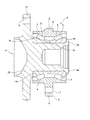
- FIG. 4 is an enlarged side view of the block taken out.
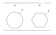
- FIG. 5 is an end view showing a second example of the shape of the guide member.
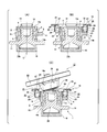
- FIG. 6 is a cross-sectional view showing, in the order of steps, how a caulking portion is formed by the rocking caulking device in the first example of the embodiment of the present invention.
- FIG. 7 is a schematic view showing a third example of the engagement state between the end of the block and the stationary flange.
- FIG. 8 is a schematic view showing another example of the block.
- FIG. 1 is a partial schematic view of a vehicle 100 provided with a hub unit bearing (bearing unit) 1.
- the present invention can be applied to any of a hub unit bearing for driving wheels and a hub unit bearing for driven wheels.
- a hub unit bearing 1 is for a driving wheel, and includes an outer ring 2A, a hub 3A, and a plurality of rolling elements 4A.
- the outer ring 2A is fixed to the knuckle 101 of the suspension system using a bolt or the like.
- the wheel (and the rotating wheel for braking) 102 is fixed to a flange (a rotating flange) 9A provided on the hub 3A using a bolt or the like.
- the vehicle 100 can have the same support structure as that described above with respect to the hub unit bearing 1 for the driven wheel.
- FIG. 2 shows a hub unit bearing (bearing unit) 1 for a driven wheel.
- the hub unit bearing 1 includes an outer ring 2, a hub 3 and a plurality of rolling elements 4.
- the outer ring 2 has a double row outer ring raceway 5 on the inner circumferential surface, and has a radially outward projecting stationary flange 6 at an axially intermediate portion.
- the stationary flange 6 has support holes 7 at a plurality of circumferential positions.
- the outer ring 2 is coupled and fixed to the knuckle of the suspension system by a bolt inserted or screwed into the support hole 7.
- Such a stationary flange 6 has a circular ring plate-like base 8 and protrusions (radius ears) projecting radially outward from a plurality of circumferential locations (four locations in the illustrated example) of the outer peripheral surface of the base 8 Part 9).
- Each of the support holes 7 is provided in the protrusion 9 so as to penetrate the protrusion 9 in the axial direction.
- the protrusion 9 has a surface (upper surface, support surface) 6 a that intersects with the axial direction.
- the hub 3 is disposed coaxially with the outer ring 2 on the inner diameter side of the outer ring 2.
- the hub 3 has double rows of inner ring races 10 on the outer peripheral surface.
- the hub 3 has a rotating flange 11 projecting radially outward at an axially outer portion projecting outward in the axial direction with respect to the axial outer end surface of the outer ring 2.
- the rotating flange 11 has mounting holes 12 at a plurality of circumferential positions. The wheel and the braking rotary body are supported and fixed to the rotating flange 11 by the stud press-fitted and fixed to the mounting hole 12 and the nut screwed to the tip of the stud.
- outside in the axial direction means the left side in FIG. 2, which is the width direction outer side of the vehicle when the hub unit bearing 1 is assembled to the suspension device, and conversely, the width direction center side of the vehicle.
- the right side of FIG. 2 is referred to as “in” in the axial direction.
- a plurality of rolling elements 4 are rollably disposed in each row between the outer races 5 of double rows and the inner races 10 of double rows.
- tapered rollers are used as the rolling elements 4.
- a ball can also be used as the rolling element 4.
- the hub 3 has a hub body (unit body) 13 and a pair of inner rings 14a and 14b.
- the double-row inner ring races 10 are provided one by one on the outer peripheral surface of the pair of inner rings 14 a and 14.
- the hub body 13 has a rotating flange 11 at the axially outer side.
- the hub body 13 has a cylindrical fitting surface portion 15 in the range from the axially middle portion to the axially inner portion of the outer peripheral surface.
- a pair of inner rings 14 a and 14 b are externally fitted to the fitting surface portion 15 of the hub body 13.
- a caulking portion 16 is provided at the axially inner end portion of the hub body 13. By the caulking portion 16, the axially inner end surface of the axially inner inner ring 14a is held down.
- the hub 3 is configured by coupling and fixing the pair of inner rings 14 a and 14 b to the hub body 13.
- FIG. 3 shows the rocking and caulking device 17.
- the rocking and caulking device 17 forms the caulking portion 16 by plastically deforming (forging, forging, pressing, pressure forming, bending) the cylindrical portion 31 (axial end portion of the cylindrical portion 31) radially outward.
- the rocking and caulking device 17 includes a support portion (base) 18 for mounting the hub main body 13 z, a rotation driving means 19 for rotationally driving the outer ring 2, and a pressing die 20.
- the support portion (base) 18 has a reference axis C in the vertical direction.
- the hub body 13z has the other axial end (axial outer end; lower end in FIG. 6A and FIG. 6B) on the lower side, and its own central axis is the reference axis C. And is placed on the upper surface of the support 18 so as to be coaxial with the
- the rotational drive means 19 includes a drive source (not shown) and an adapter (rotational drive jig) 80.
- the outer ring 2 moves around the axis of the hub body 13z through the adapter 80.
- the adapter 80 includes a support plate (adapter body) 21 and a plurality of (eight in the illustrated example) blocks 22.
- the support plate 21 is configured in the shape of a circular ring centered on a central axis coaxial with the reference axis C of the support portion 18. Further, the support plate 21 (adapter body) is supported so as to be able to move up and down above the support portion 18, that is, to be able to move in a perspective direction with respect to the support portion 18.
- the support plate 21 is rotatably supported centering on a central axis coaxial with the reference axis C, and is configured to be rotationally driven by a drive source (not shown) such as an electric motor. Moreover, the support plate 21 has the seat part 23 dented upwards in the circumferential direction multiple places of the lower surface. Positioning of an elastic member (biasing member) 27 described later and prevention of buckling are achieved by such a seat portion 23.
- each of the blocks 22 is at least partially made of a resin material.
- the block 22 is made of a material other than resin.
- the block 22 includes a block body 24 and a guide member 25 made of synthetic resin.
- the block body 24 is configured in a stepped cylindrical shape.
- the guide member 25 is externally fitted and supported by the tip (lower end) of the block body 24.
- the guide member 25 is a rolling bearing or a sliding bearing having a circular shape as viewed in the axial direction as shown in FIG. 5 (A).
- the block main body 24 can rotate.
- the guide member 25 may have a shape as viewed in the axial direction, for example, a polygon (preferably, a regular polygon) such as a regular hexagon as shown in FIG. 5 (B).
- the block 22 can also be configured in a prismatic shape whose cross-sectional shape is a regular polygon such as a square or a regular hexagon.
- a rolling bearing or a sliding bearing whose outer peripheral surface is a cylindrical surface can be externally supported at the tip of the block.
- a rolling bearing When a rolling bearing is used as the guide member 25, it is preferable to cover the outer peripheral surface of the outer ring with a synthetic resin such as urethane, silicone, polyacetal, or MC nylon (registered trademark), which is a type of polyamide resin.
- a synthetic resin such as urethane, silicone, polyacetal, or MC nylon (registered trademark), which is a type of polyamide resin.
- the outer peripheral surface of the guide member 25 can prevent the metals from colliding with each other when pushing the circumferential side surface of the projection 9 of the stationary flange 6. Can be prevented from being damaged.
- a shaft-equipped rolling bearing in which a rotating shaft is supported and fixed in advance on the inner ring can also be used as the guide member 25. That is, the guide member 25 can be provided at the tip of the block main body 24 by supporting and fixing the rotary shaft of the shaft-equipped rolling bearing at the tip of the block main body 24 by tight fitting or screwing.
- the plurality of blocks 22 are disposed movably in the axial direction of the hub body 13z with respect to the support plate 21.
- the support plate 21 has a plate member (annular plate member) 21 a and a housing member (cover, boss, boss wall, annular wall) 26.
- the plate member 21a and the housing member 26 are integrally formed.
- the housing member 26 is fixed to the plate member 21a.
- the housing member 26 is disposed to surround the hub body 13z.
- the housing member 26 has a cavity (or notch) 26 a in which at least a part of the block 22 is housed.
- Each of the plurality of blocks 22 is axially movably disposed between a projected state in which at least a portion of the block 22 axially protrudes from the support plate 21 (adapter body, receiving member 26) and a stored state. Be done.
- the axial end surface of the block 22 is in contact with the upper surface 6 a (first surface) of the stationary flange 6 of the outer ring 2.
- the side surface (peripheral surface) of the block 22 is disposed to face the side surface (the side surface of the protrusion 9, the second surface) of the stationary flange 6 of the outer ring 2.
- the support plate 21 (adapter 80) has a biasing member (elastic member) 27 that applies a force in a direction toward the hub body 13z to the block 22.
- the block 22 is supported below the support plate 21 with a downward elastic force applied. That is, the block 22 is fitted in a cylindrical cover 26 supported on the lower surface of the support plate 21 so as to surround the opening of the seat 23.
- An elastic member (biasing member) 27 such as a torsion coil spring is disposed between the upper end surface of the block 22 and the bottom surface of the seat portion 23.
- the resilient member 27 allows the block 22 to be reliably projected relative to the support plate 21.
- an actuator may be provided to move the block 22 in the axial direction.
- the elastic member 27 can be omitted by using gravity or magnetic force.
- the pressing die 20 is disposed so as to perform caulking motion (swinging caulking motion, swinging motion) with respect to the hub body 13z to which the inner ring 14a is attached.
- the die 20 has a main axis ⁇ which is coaxial with the reference axis C, and a rotation axis ⁇ which is inclined by a predetermined angle ⁇ with respect to the main axis ⁇ .
- the pressing die 20 has a processing portion 28 at the tip end portion (lower end portion) for plastically deforming the cylindrical portion 31 of the hub main body 13 z radially outward to form the caulking portion 16.
- the processing portion 28 is configured by providing a convex portion 29 at the tip end portion of the die 20 and providing a curved surface portion 30 having an arc-shaped cross section on the outer peripheral surface of the base end portion of the convex portion 29. .
- a pressing die 20 is supported so as to be able to move up and down above the rotation drive means 19. Further, the pressing die 20 can be rotationally driven about the main axis ⁇ , and is rotatable around the rotation axis ⁇ .
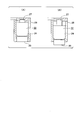
- FIG. 6A the hub main body 13z before forming the caulking portion 16 is positioned such that the other axial end is on the lower side, and the central axis of the hub main body 13z is the reference axis C. , And placed on the support 18 of the rocking and caulking device 17 so as to be coaxial with the above.
- the pair of inner rings 14a and 14b, the plurality of rolling elements 4 and the outer ring 2 are assembled around the fitting surface portion 15 of the hub body 13z.
- the order in which the pair of inner rings 14a and 14b, the plurality of rolling elements 4 and the outer ring 2 are assembled around the fitting surface portion 15 is not particularly limited. Specifically, for example, first, the axially outer inner ring 14b is externally fitted to the axially outer half of the fitting surface portion 15, and the rolling elements 4 are installed around the axially outer inner ring 14b. Next, the outer ring 2 is disposed around the fitting surface portion 15. Then, the rolling element 4 is installed around the inner ring 14 a on the axially inner side to make a subassembly, and this subassembly is made between the axially inner half portion of the fitting surface portion 15 and the outer ring raceway 5 on the inner shaft. insert.
- the pair of inner rings 14a and 14b, the plurality of rolling elements 4 and the outer ring 2 may be made into a subassembly in advance, and this subassembly may be installed around the fitting surface portion 15.
- the plurality of rolling elements 4 and the outer ring 2 are assembled around the fitting surface portion 15, then, as shown in FIG. Displace downward. Thereby, at least one block 22 of the plurality of blocks 22 and the projection 9 of the stationary flange 6 are engaged with respect to the direction around the axis of the hub body 13z (rotational direction of the outer ring 2 by the rotation drive means 19) It will be in a compatible state (projected state).
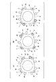
- the blocks 22 of the adapter 80 of the rotational drive means 19 are arranged at a plurality of circumferentially equidistantly spaced locations centered on a central axis coaxial with the reference axis C of the support portion 18. Therefore, as shown in FIGS. 7A to 7C, some blocks 22 of the blocks 22 (blocks 22 represented by dashed-dotted lines in FIGS. 7A to 7C) At least a part of the front end face of the stationary flange 6 faces the axial end face of the projection 9 of the stationary flange 6, and the remaining blocks 22 are disposed in a portion circumferentially offset from the projection 9.
- An axial end face (tip surface and lower surface) of at least one block 22 (and a part of the lower surface of the support plate 21) is in contact with the upper surface 6 a (first surface) of the stationary flange 6 of the outer ring 2.
- the at least one block 22 is stored in the support plate 21.
- the remaining block 22 is in a projecting state in which at least a part of the block 22 axially protrudes from the support plate 21 (adapter body, receiving member 26).
- the side surface (peripheral surface) of the block 22 is disposed facing the side surface (the side surface of the protrusion 9, the second surface) of the stationary flange 6 of the outer ring 2.
- the block 22 is provided with a resilient force directed downward by the elastic member 27. Therefore, in a state in which the elastic member 27 is not elastically deformed, and in the vertical direction of the tip end surface (lower end surface) of the block 22 opposed to the axial inner surface of the protrusion 9 and the axial inner surface of the stationary flange 6 When the adapter 80 of the rotational drive unit 19 is further displaced downward from the state where the positions coincide, a part of the blocks 22 (the tip end faces the inner side in the axial direction of the protrusion 9) is the elastic member 27. By elastically deforming, it remains at the same position in the vertical direction.
- the remaining blocks 22 (the tip end faces the part circumferentially deviated from the protrusion 9) are displaced downward together with the support plate 21, and the guide members 25 of the remaining blocks 22 are circumferentially It arrange
- the adapter 80 of the rotational drive means 19 is rotationally driven clockwise in FIG. 7 about a central axis coaxial with the reference axis C. Then, with the outer peripheral surface of the guide member 25 of at least one of the blocks 22 (block 22 represented by thick lines in FIGS. 7A to 7C), at least one side of the protrusion 9 is a circle. It is pushed in the circumferential direction. At this time, for example, a part of the block 22 abuts on the support plate 21 and the posture of the block 22 is maintained.
- the rolling elements 4 rotate and revolve. As described later, when the caulking portion 16 is formed, the formation of an indentation on the outer ring raceway 5 and the inner ring raceway 10 is prevented.
- the die 20 is displaced downward while swinging movement of the rotation axis ⁇ of the die 20 about the main axis ⁇ as the locus of the central axis by the precession motion.
- the processed portion 28 of the die 20 is pressed against the cylindrical portion 31 of the hub body 13z.
- the number of rotations (rotational speed) of the swinging motion of the rotation axis ⁇ of the die 20 about the main axis ⁇ is made different from the number of rotations (rotational speed) of the rotation drive means 19.
- the swinging movement of the pressing die 20 is stopped, and the pressing die 20 is retracted upward.
- the rotation driving means 19 is stopped to stop the rotation of the outer ring 2, and thereafter, the adapter 80 of the rotation driving means 19 is retracted upward.
- the hub unit bearing 1 is obtained by removing the hub main body 13 from the support portion 18.
- the blocks 22 are arranged at a plurality of circumferentially equally spaced locations. Further, each block 22 is given a downward elastic force by an elastic member 27. Therefore, the block 22 whose tip end face the axially inner side (the inner side of the projection 9 in the axial direction) of the stationary flange 6 is the tip end face of the block 22 as the rotary drive means 19 is displaced downward. And the axially inner surface of the stationary flange 6 abut. Even when the rotational drive means 19 (adapter 80) is displaced further downward, the elastic member 27 is elastically deformed and remains at the vertical position as it is.
- a guide member 25 which is a rolling bearing or a sliding bearing using a synthetic resin is rotatably supported at the end of the block 22.
- the outer peripheral surface of the guide member 25 pushes the side surface of the protrusion 9 of the stationary flange 6 in the circumferential direction. This prevents damage such as scratches from being generated on the side surface in the circumferential direction of the protrusion 9 and prevents the outer peripheral surface of the guide member 25 from being worn.
- the elastic member 27 disposed between the support plate 21 and the block 22 can be omitted.
- the number of blocks of the rotary drive means and the arrangement in the circumferential direction when the rotary drive means is displaced in the direction approaching the support portion, the circumference of the rotary drive means and the stationary flange. Regardless of the phase with respect to the direction, at least one of the blocks constituting the rotary drive means and the stationary flange can be engaged so as to be able to transmit power in the rotational direction. It is preferable to set appropriately according to the shape. That is, as long as at least one block and the stationary flange can be engaged so as to transmit power in the rotational direction, the plurality of blocks can be arranged at uneven intervals in the circumferential direction.
- the number of blocks can be set according to the shape of the stationary flange, and can be 1, 2, 3, 4, 5, 6, 7, 8, 9, 10, or 11 or more. For example, the number of blocks is preferably 6 to 8.
- the number of blocks may be six or less or one.
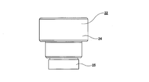
- FIG. 8 shows another example of the block 22.
- the entire guide member 25 of the block 22 is disposed inside the housing member 26 of the support plate (adapter main body) 21.
- FIG. 8B in the protruding state, a part of the guide member 25 of the block 22 protrudes with respect to the support plate 21 and the remaining part of the guide member 25 is a storage member 26 in the support plate 21. Placed inside the
- the present invention is not only a hub unit bearing for a driven wheel in which the hub body is solid, but also a drive wheel provided with a spline hole for engaging the drive shaft in a torque transmittable manner at the central portion of the hub body. It can also be applied to hub unit bearings. Also, the case has been described above in which the present invention is applied to a so-called 2.5th generation hub unit bearing provided with a hub in which a pair of inner rings are externally fitted to a hub body.
- the present invention is a so-called third generation, having a hub in which the axially outer inner ring raceway is directly formed on the axially outer peripheral surface of the hub body and the inner ring is externally fitted on the axially inner side of the hub body.
- the present invention can also be applied to hub unit bearings that are loose.
Landscapes
- Engineering & Computer Science (AREA)
- Mechanical Engineering (AREA)
- General Engineering & Computer Science (AREA)
- Rolling Contact Bearings (AREA)
- Mounting Of Bearings Or Others (AREA)
- Forging (AREA)
- Sliding-Contact Bearings (AREA)
Priority Applications (5)
| Application Number | Priority Date | Filing Date | Title |
|---|---|---|---|
| US16/634,715 US11077484B2 (en) | 2017-11-20 | 2018-10-25 | Rotary caulking device, method of manufacturing hub unit bearing and method of manufacturing vehicle |
| KR1020207009911A KR102639868B1 (ko) | 2017-11-20 | 2018-10-25 | 요동 스웨이징 장치, 허브 유닛 베어링의 제조 방법 및 차량의 제조 방법 |
| EP18878203.1A EP3533526B1 (en) | 2017-11-20 | 2018-10-25 | Rotary swaging device, method for manufacturing hub unit bearing, and method for manufacturing vehicle |
| JP2019513857A JP6558517B1 (ja) | 2017-11-20 | 2018-10-25 | 揺動かしめ装置、ハブユニット軸受の製造方法および車両の製造方法 |
| US17/325,675 US11745249B2 (en) | 2017-11-20 | 2021-05-20 | Rotary caulking device, method of manufacturing hub unit bearing and method of manufacturing vehicle |
Applications Claiming Priority (2)
| Application Number | Priority Date | Filing Date | Title |
|---|---|---|---|
| JP2017-223090 | 2017-11-20 | ||
| JP2017223090 | 2017-11-20 |
Related Child Applications (2)
| Application Number | Title | Priority Date | Filing Date |
|---|---|---|---|
| US16/634,715 A-371-Of-International US11077484B2 (en) | 2017-11-20 | 2018-10-25 | Rotary caulking device, method of manufacturing hub unit bearing and method of manufacturing vehicle |
| US17/325,675 Division US11745249B2 (en) | 2017-11-20 | 2021-05-20 | Rotary caulking device, method of manufacturing hub unit bearing and method of manufacturing vehicle |
Publications (1)
| Publication Number | Publication Date |
|---|---|
| WO2019097972A1 true WO2019097972A1 (ja) | 2019-05-23 |
Family
ID=66538578
Family Applications (1)
| Application Number | Title | Priority Date | Filing Date |
|---|---|---|---|
| PCT/JP2018/039596 Ceased WO2019097972A1 (ja) | 2017-11-20 | 2018-10-25 | 揺動かしめ装置、ハブユニット軸受の製造方法および車両の製造方法 |
Country Status (5)
| Country | Link |
|---|---|
| US (2) | US11077484B2 (enExample) |
| EP (1) | EP3533526B1 (enExample) |
| JP (2) | JP6558517B1 (enExample) |
| KR (1) | KR102639868B1 (enExample) |
| WO (1) | WO2019097972A1 (enExample) |
Families Citing this family (2)
| Publication number | Priority date | Publication date | Assignee | Title |
|---|---|---|---|---|
| CN113335554B (zh) * | 2021-04-30 | 2022-07-15 | 成都飞机工业(集团)有限责任公司 | 一种轴孔同轴度定位组件及使用该定位组件的定位方法 |
| CN114659587B (zh) * | 2022-05-24 | 2022-08-02 | 南京一淳科技有限公司 | 一种用于复杂工况的雷达物位计装置和方法 |
Citations (5)
| Publication number | Priority date | Publication date | Assignee | Title |
|---|---|---|---|---|
| JP2003021153A (ja) | 2001-07-05 | 2003-01-24 | Koyo Seiko Co Ltd | 軸受装置の組み立て方法 |
| JP2005121211A (ja) * | 2003-07-24 | 2005-05-12 | Snr Roulements | 連続転位を伴う保持カラーの製造方法 |
| JP2006132711A (ja) * | 2004-11-08 | 2006-05-25 | Nsk Ltd | 車輪支持用ハブユニットの製造方法 |
| JP2006153053A (ja) * | 2004-11-25 | 2006-06-15 | Jtekt Corp | 軸受装置の組み付け装置およびその組み付け方法 |
| JP2017223090A (ja) | 2016-06-17 | 2017-12-21 | 株式会社大和エンジニヤリング | 門扉 |
Family Cites Families (4)
| Publication number | Priority date | Publication date | Assignee | Title |
|---|---|---|---|---|
| JPH1144319A (ja) * | 1997-07-29 | 1999-02-16 | Nippon Seiko Kk | 軸受の予圧付与装置 |
| JP4082000B2 (ja) * | 2001-07-19 | 2008-04-30 | 日本精工株式会社 | 車輪支持用転がり軸受ユニットの製造方法及び製造装置 |
| JP2005172049A (ja) * | 2003-12-09 | 2005-06-30 | Nsk Ltd | 車輪支持用転がり軸受ユニットの製造方法 |
| US20070217728A1 (en) | 2004-09-30 | 2007-09-20 | Shinichirou Kashiwagi | Hub Unit, Rolling Bearing Assembly and Manufacture Method Thereof, as Well as Assembling Apparatus for Rolling Bearing Assebly and Assebly Method Thereof |
-
2018
- 2018-10-25 JP JP2019513857A patent/JP6558517B1/ja active Active
- 2018-10-25 KR KR1020207009911A patent/KR102639868B1/ko active Active
- 2018-10-25 EP EP18878203.1A patent/EP3533526B1/en active Active
- 2018-10-25 US US16/634,715 patent/US11077484B2/en active Active
- 2018-10-25 WO PCT/JP2018/039596 patent/WO2019097972A1/ja not_active Ceased
-
2019
- 2019-07-17 JP JP2019132030A patent/JP7263955B2/ja active Active
-
2021
- 2021-05-20 US US17/325,675 patent/US11745249B2/en active Active
Patent Citations (5)
| Publication number | Priority date | Publication date | Assignee | Title |
|---|---|---|---|---|
| JP2003021153A (ja) | 2001-07-05 | 2003-01-24 | Koyo Seiko Co Ltd | 軸受装置の組み立て方法 |
| JP2005121211A (ja) * | 2003-07-24 | 2005-05-12 | Snr Roulements | 連続転位を伴う保持カラーの製造方法 |
| JP2006132711A (ja) * | 2004-11-08 | 2006-05-25 | Nsk Ltd | 車輪支持用ハブユニットの製造方法 |
| JP2006153053A (ja) * | 2004-11-25 | 2006-06-15 | Jtekt Corp | 軸受装置の組み付け装置およびその組み付け方法 |
| JP2017223090A (ja) | 2016-06-17 | 2017-12-21 | 株式会社大和エンジニヤリング | 門扉 |
Also Published As
| Publication number | Publication date |
|---|---|
| JP7263955B2 (ja) | 2023-04-25 |
| JP2019214074A (ja) | 2019-12-19 |
| EP3533526B1 (en) | 2020-09-09 |
| EP3533526A4 (en) | 2019-11-13 |
| JPWO2019097972A1 (ja) | 2019-11-14 |
| KR20200085731A (ko) | 2020-07-15 |
| US11745249B2 (en) | 2023-09-05 |
| EP3533526A1 (en) | 2019-09-04 |
| US20200298300A1 (en) | 2020-09-24 |
| KR102639868B1 (ko) | 2024-02-22 |
| US11077484B2 (en) | 2021-08-03 |
| US20210268568A1 (en) | 2021-09-02 |
| JP6558517B1 (ja) | 2019-08-14 |
Similar Documents
| Publication | Publication Date | Title |
|---|---|---|
| JP6624354B1 (ja) | 揺動加工装置、ハブユニット軸受の製造方法および自動車の製造方法 | |
| US10442040B2 (en) | Assembling device of wheel hub unit | |
| JP7243703B2 (ja) | 軸受保持体 | |
| JP2019181571A5 (enExample) | ||
| JP7512977B2 (ja) | かしめアセンブリの製造方法、ハブユニット軸受の製造方法、かしめ装置、及び車両の製造方法 | |
| JP4127266B2 (ja) | 車輪支持用転がり軸受ユニットの製造方法及び製造装置 | |
| US11745249B2 (en) | Rotary caulking device, method of manufacturing hub unit bearing and method of manufacturing vehicle | |
| WO2016013668A1 (ja) | 転がり軸受ユニットの製造方法 | |
| JP4644960B2 (ja) | 自動車用ハブユニットの組立方法 | |
| JP2019211084A (ja) | ハブユニット軸受およびその製造方法、並びに、自動車およびその製造方法 | |
| JP6222197B2 (ja) | 転がり軸受ユニットの製造方法及び製造装置、車両の製造方法 | |
| JP2017067254A5 (enExample) | ||
| JP4720032B2 (ja) | 軸受装置の組み立て方法 | |
| JP2018149599A (ja) | 車輪支持用軸受ユニットの製造方法及び製造装置、並びに車両の製造方法 | |
| KR101322427B1 (ko) | 휠 베어링 조립체의 제작 장치, 휠 베어링 조립체의 오비탈 포밍 방법 및 오비탈 포밍 가공 장치 | |
| JP2024063471A (ja) | 車輪用軸受装置の製造方法及び製造装置 | |
| JP4042528B2 (ja) | 転がり軸受装置 | |
| JP2009002480A5 (enExample) | ||
| CN116194234A (zh) | 轴承单元用的铆接装置及铆接方法、轮毂单元轴承的制造方法及制造装置、车辆的制造方法 | |
| JP2024130352A (ja) | ハブユニット軸受 | |
| JP2022134633A (ja) | 車輪用軸受装置 | |
| JP2005106198A (ja) | 車輪用転がり軸受装置およびその加工方法 | |
| JP2017161062A (ja) | プロペラシャフトの製造方法 |
Legal Events
| Date | Code | Title | Description |
|---|---|---|---|
| ENP | Entry into the national phase |
Ref document number: 2019513857 Country of ref document: JP Kind code of ref document: A |
|
| ENP | Entry into the national phase |
Ref document number: 2018878203 Country of ref document: EP Effective date: 20190528 |
|
| 121 | Ep: the epo has been informed by wipo that ep was designated in this application |
Ref document number: 18878203 Country of ref document: EP Kind code of ref document: A1 |