WO2019097914A1 - 空調システム - Google Patents
空調システム Download PDFInfo
- Publication number
- WO2019097914A1 WO2019097914A1 PCT/JP2018/037971 JP2018037971W WO2019097914A1 WO 2019097914 A1 WO2019097914 A1 WO 2019097914A1 JP 2018037971 W JP2018037971 W JP 2018037971W WO 2019097914 A1 WO2019097914 A1 WO 2019097914A1
- Authority
- WO
- WIPO (PCT)
- Prior art keywords
- air
- outlet
- blown out
- air conditioning
- amount
- Prior art date
- Legal status (The legal status is an assumption and is not a legal conclusion. Google has not performed a legal analysis and makes no representation as to the accuracy of the status listed.)
- Ceased
Links
Images


Classifications
-
- B—PERFORMING OPERATIONS; TRANSPORTING
- B60—VEHICLES IN GENERAL
- B60H—ARRANGEMENTS OF HEATING, COOLING, VENTILATING OR OTHER AIR-TREATING DEVICES SPECIALLY ADAPTED FOR PASSENGER OR GOODS SPACES OF VEHICLES
- B60H1/00—Heating, cooling or ventilating [HVAC] devices
-
- B—PERFORMING OPERATIONS; TRANSPORTING
- B60—VEHICLES IN GENERAL
- B60H—ARRANGEMENTS OF HEATING, COOLING, VENTILATING OR OTHER AIR-TREATING DEVICES SPECIALLY ADAPTED FOR PASSENGER OR GOODS SPACES OF VEHICLES
- B60H1/00—Heating, cooling or ventilating [HVAC] devices
- B60H1/32—Cooling devices
-
- B—PERFORMING OPERATIONS; TRANSPORTING
- B60—VEHICLES IN GENERAL
- B60H—ARRANGEMENTS OF HEATING, COOLING, VENTILATING OR OTHER AIR-TREATING DEVICES SPECIALLY ADAPTED FOR PASSENGER OR GOODS SPACES OF VEHICLES
- B60H1/00—Heating, cooling or ventilating [HVAC] devices
- B60H1/34—Nozzles; Air-diffusers
Definitions
- the present disclosure relates to an air conditioning system for a vehicle.
- an air conditioning system for air conditioning a vehicle interior is known.
- the air conditioning system described in Patent Document 1 adjusts the air volume of conditioned air blown out from an outlet provided in an instrument panel according to the position of a front seat moving in the longitudinal direction of the vehicle. Specifically, the air conditioning system reduces the amount of air blown out from the outlet as the position of the front seat approaches the outlet, and the amount of air blown out from the outlet as the position of the front seat moves farther from the outlet. Increase the Thus, the air conditioning system provides a certain degree of air conditioning to the occupant seated in the front seat.
- the air conditioning system described in Patent Document 1 requires a large amount of air when the position of the front seat is far from the air outlet, so the load of the blower and the compressor that constitutes the refrigeration cycle of the air conditioner becomes large. Therefore, the life of the air conditioner may be shortened. Further, in the air conditioning system, when the position of the front seat is far from the air outlet, the air conditioned air blown out from the air outlet diffuses before reaching the occupant. As a result, since the occupant can not be given a strong feeling of air conditioning having a punching power, there is a concern that the occupant may feel a lack of objectivity.
- the present disclosure aims to provide an air conditioning system capable of reducing the load on the air conditioner and enhancing the comfort of the occupant.
- an air conditioning system mounted on a vehicle including a front seat having at least a portion of a movable portion movable in the longitudinal direction of the vehicle, A first air blower having a first air blower for blowing air conditioning air, and a first air outlet having a first air outlet blowing out air conditioning air blown by the first air blower from a front of the vehicle to an occupant seated in a front seat; A second air blower having a second blower for blowing the air conditioning air, and a second air outlet for blowing the air conditioning air blown by the second blower from the rear of the vehicle to an occupant seated in the front seat; A position detection unit that detects the position or angle of the movable unit of the front seat; A control device that controls driving of the first air conditioner and the second air conditioner according to the position or angle of the movable part detected by the position detection unit; The controller is In all or part of the range in which the movable part moves in the longitudinal direction of the vehicle, As the
- the air conditioning capacity by the air conditioning wind blown out from the blowout port closer to the movable portion of the front seat among the first blowout port and the second blowout port is increased, the air conditioning having a so-called punch power is strong Can give a feeling.
- the conditioned air blown out from each of the first and second outlets collides with each other in the vicinity of the occupant, so that the conditioned air can be retained in the vicinity of the occupant. Therefore, compared with the case where the air is blown from any one of the first and second air outlets, the diffusion of the conditioned air is suppressed, so that the area near the occupant can be efficiently air-conditioned. Therefore, this air conditioning system can reduce the load on the individual air conditioners and enhance the comfort of the occupant.
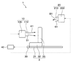
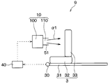
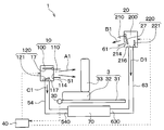
- the air conditioning system 1 of the present embodiment is mounted on the vehicle 2 and blows out conditioned air whose temperature and humidity are adjusted according to a predetermined air conditioning mode from a plurality of outlets into the vehicle compartment, thereby performing air conditioning of the vehicle interior. It is a thing.
- the vehicle 2 includes a front seat 3 and a rear seat 4.
- the front seat 3 has a rail 31 extending in the front-rear direction of the vehicle, and a seat 32 and a backrest 33 movable on the rail 31.
- the seat portion 32 of the front seat 3 corresponds to a movable portion movable in the longitudinal direction of the vehicle.
- the air conditioning system 1 includes a first air conditioner 10, a second air conditioner 20, a position detection unit 30, a control device 40, and the like.
- the first air conditioner 10 is provided inside the instrument panel 5.
- the first air conditioner 10 generates a first air conditioning unit 100 that generates conditioned air and a first blow that blows out the conditioned air generated by the first air conditioning unit 100 from the front of the vehicle to the occupant 6 seated on the front seat 3. It has an outlet 110.
- FIG. 4 is a schematic view of the first air conditioner 10.
- the first air conditioner 10 includes a first air conditioning unit 100 and a plurality of ducts 51, 52, 53.
- the outlet of the face duct 51 corresponds to the first outlet 110 described above.
- the face duct 51 can blow conditioned air toward the upper body or the periphery of the occupant 6 seated on the front seat 3 from the first outlet 110 provided in the instrument panel 5.
- the first air conditioner 10 may integrally configure the first air conditioning unit 100 and the plurality of ducts 51, 52, 53. Alternatively, the conditioned air may be directly blown out from the blowout openings 114, 115, 116 of the first air conditioner 10.
- the configuration of the first air conditioning unit 100 will be described.
- the first air conditioning unit 100 includes an inside / outside air switching door 12, a blower 13, an evaporator 14, a heater core 15, an air mixing door 16, mode switching doors 17, 18, 19 and the like inside the air conditioning case 11.
- the air conditioning case 11 introduces outside air into the air flow passage 111 from the outside of the vehicle and the inside air introduction port 112 for introducing the air into the air flow passage 111 from a predetermined location in the vehicle room on the air flow direction upstream side of the air flow passage 111 It has an outside air introduction port 113 for.
- the inside / outside air switching door 12 continuously adjusts the opening area of the inside air introduction port 112 and the opening area of the outside air introduction port 113.
- the inside / outside air switching door 12 rotates so as to close the other opening as the opening of one of the inside air introduction port 112 and the outside air introduction port 113 is opened.
- the inside / outside air switching door 12 can adjust the ratio of the air volume of the inside air introduced into the ventilation path 111 and the air volume of the outside air.
- the blower 13 is composed of a centrifugal fan 131, a motor 132 for rotationally driving the centrifugal fan 131, and the like.
- the centrifugal fan 131 rotates with the drive of the motor 132, air is blown to the air passage 111.
- inside air or outside air is introduced into the ventilation path 111 from the inside air introduction port 112 or the outside air introduction port 113.
- the temperature and humidity of the air blown by the blower 13 and flowing through the ventilation path 111 are adjusted by the evaporator 14 and the heater core 15, and any of the plurality of blowout openings 114, 115, 116 communicating with the ventilation path 111 It is blown out into the passenger compartment.
- the evaporator 14 is a heat exchanger for cooling the air flowing through the air passage 111.
- the evaporator 14 constitutes a known refrigeration cycle together with a compressor, a condenser, an expansion valve and the like which are not shown.
- the refrigerant in a gas-liquid two-layer state flows through a tube (not shown) of the evaporator 14.
- the evaporator 14 cools the air flowing through the air passage 111 by the latent heat of evaporation of the refrigerant flowing inside the tube.
- the heater core 15 is a heat exchanger for heating the air flowing through the air passage 111. Hot water or the like flows inside the tube (not shown) of the heater core 15. The heater core 15 heats the air flowing through the air passage 111 by heat exchange between the warm water flowing inside the tube and the air flowing through the air passage 111.
- An air mix door 16 is provided between the evaporator 14 and the heater core 15.
- the air mix door 16 adjusts the ratio of the air volume flowing around the heater core 15 after passing through the evaporator 14 and the air volume passing through the heater core 15 after passing through the evaporator 14.
- the air conditioning case 11 has, on the downstream side in the air flow direction of the air passage 111, a plurality of blowout openings 114, 115, 116 for blowing air from the air passage 111 into the vehicle compartment.
- the plurality of blowout openings 114, 115, 116 are configured by, for example, a face blowout opening 114, a foot blowout opening 115, a defroster blowout opening 116, and the like.
- the face blowout opening 114 blows the conditioned air toward the upper body of the occupant 6 seated in the front seat 3 or the periphery thereof.
- the foot blowout opening 115 blows the conditioned air toward the feet of the occupant 6.
- the defroster blowout opening 116 blows the conditioned air toward the windshield of the vehicle 2.
- the face blowing opening 114, the foot blowing opening 115, and the defroster blowing opening 116 are provided with mode switching doors 17, 18 and 19 for opening and closing the respective openings.
- the mode switching doors 17, 18, 19 are configured by the face door 17, the foot door 18 and the defroster door 19.
- the face door 17 opens and closes the face blowout opening 114.
- the foot door 18 opens and closes the foot outlet opening 115.
- the defroster door 19 opens and closes the defroster blowout opening 116.
- the inside / outside air switching door 12, the air mix door 16, the face door 17, the foot door 18, and the defroster door 19 described above are each driven by an actuator such as a servomotor (not shown).
- a plurality of ducts 51, 52, 53 configured as separate members from the air conditioning case 11 are connected to the plurality of air outlet openings 114, 115, 116 of the air conditioning case 11 of the first air conditioning unit 100, respectively.
- the plurality of ducts 51, 52, 53 are constituted by, for example, the face duct 51, the foot duct 52, the defroster duct 53, and the like.
- the face duct 51 is connected to the face outlet 114.
- the foot duct 52 is connected to the foot outlet opening 115.
- the defroster duct 53 is connected to the defroster blowout opening 116.
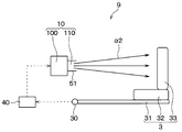
- the second air conditioner 20 generates a second air conditioning unit 200 that generates conditioned air, and a second outlet that blows out the conditioned air generated by the second air conditioning unit 200 from the rear of the vehicle to the occupant 6 who sits on the front seat 3 It has 210.
- the second air conditioning unit 200 is installed on the vehicle ceiling in FIGS. 1 to 3, the position at which the second air conditioning unit 200 is installed is not limited to this.
- the second air conditioning unit 200 can be installed at any place, such as the vehicle ceiling, the rear of the rear seat 4, or the side of the rear seat 4, for example.
- FIG. 5 is a schematic view of the second air conditioner 20.
- the second air conditioner 20 includes a second air conditioning unit 200 and a plurality of ducts 61 and 62.
- the second air conditioning unit 200 also includes an inside / outside air switching door 22, a blower 23, an evaporator 24, a heater core 25, an air mix door 26, a mode switching door 27, 28 and the like inside the air conditioning case 21. Is equipped.
- the blower 23 is composed of a centrifugal fan 231, a motor 232 for rotationally driving the centrifugal fan 231, and the like.
- a ceiling outlet opening 214 and a foot outlet opening 215 are provided on the downstream side of the air passage 211 of the air conditioning case 21 of the second air conditioning unit 200, and no defroster outlet is provided.
- a ceiling duct 61 is connected to the ceiling blowout opening 214 provided in the air conditioning case 21 of the second air conditioning unit 200.
- the outlet of the ceiling duct 61 corresponds to the second outlet 210 described above.
- the ceiling duct 61 can blow conditioned air toward the upper body or the periphery of the occupant 6 seated on the front seat 3 from the second air outlet 210 provided in the vehicle ceiling.
- the second air conditioner 20 may also integrally configure the second air conditioning unit 200 and the plurality of ducts 61 and 62. Alternatively, the conditioned air may be directly blown out from the blowout openings 214 and 215 of the second air conditioner 20.
- the respective components included in the first air conditioning unit 100 are appropriately referred to as the first air conditioning case 11, the first inside / outside air switching door 12, the first blower 13, the first evaporator 14, the first heater core 15, the first air It may be called the mix door 16 and the first mode switching door 17, 18, 19.
- each configuration of the second air conditioning unit 200 may be appropriately determined by the second air conditioning case 21, the second inside / outside air switching door 22, the second blower 23, the second evaporator 24, the second heater core 25, the second air mix door 26. And the second mode switching door 27, 28.
- the air conditioning system 1 drives the first air conditioner 10 and the second air conditioner 20 according to the position of the seat 32 as the movable portion of the front seat 3.
- the control device 40 controls the position of the seat portion 32 of the front seat 3 and the position detection unit 30 according to the position of the seat 32 as the movable portion of the front seat 3.
- the position of the seat portion 32 of the front seat 3 is detected by the position detection unit 30.
- the position information of the seat portion 32 of the front seat 3 detected by the position detection unit 30 is transmitted to the control device 40.
- the control device 40 is configured by a computer having a processor, a memory, and the like, and peripheral circuits thereof.
- the memory of the control device 40 is configured of a non-transitional tangible storage medium.
- the first air conditioner 10 and the second air conditioner 20 are described as being driven and controlled by one control device 40 in FIGS. 1 to 3, the number and arrangement of the control devices 40 are the same. Not limited to.
- the first air conditioner 10 and the second air conditioner 20 may be drive-controlled by separate control devices.
- the control device 40 controls the driving of the first air conditioner 10 and the second air conditioner 20 according to the position of the seat portion 32 of the front seat 3 detected by the position detection unit 30.
- the control device 40 controls the driving of the first air conditioner 10 and the second air conditioner 20 in the whole area or a part of the range in which the seat portion 32 of the front seat 3 moves in the vehicle longitudinal direction.
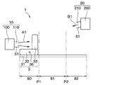
- FIG. 2 shows a state where the seat portion 32 is positioned at the forefront in a range in which the seat portion 32 of the front seat 3 moves in the longitudinal direction of the vehicle.
- the control device 40 increases the air conditioning capacity by the conditioned air blown out from the first outlet 110 as the seat 32 of the front seat 3 gets closer to the first outlet 110, and the air conditioner blown out from the second outlet 210
- the air conditioning capacity of the second air conditioner 20 by wind is reduced.
- the control device 40 increases the amount of air blown from the first air outlet 110 as the seat portion 32 of the front seat 3 approaches the first air outlet 110, and blows the air from the second air outlet 210.
- the drive of the first blower 13 and the second blower 23 is controlled so as to reduce the air volume.
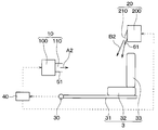
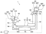
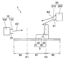
- FIG. 3 shows a state in which the seat portion 32 is located at the rearmost position in the range in which the seat portion 32 of the front seat 3 moves in the vehicle longitudinal direction.
- the control device 40 increases the air conditioning capacity by the air conditioning air blown out from the second air outlet 210 as the seat portion 32 of the front seat 3 approaches the second air outlet 210, and the air conditioning blown out from the first air outlet 110 Reduce the air conditioning capacity by wind.
- the control device 40 increases the amount of air blown from the second air outlet 210 as the seat 32 of the front seat 3 approaches the second air outlet 210 and blows the air from the first air outlet 110
- the drive of the first blower 13 and the second blower 23 is controlled so as to reduce the air volume.
- the control device 40 automatically adjusts the vertical angle of the air-conditioning air blown from the second air outlet 210 according to the position of the seat portion 32 of the front seat 3 in the blowing direction.
- the total air conditioning capacity supplied to the occupant 6 is set to be substantially the same.
- the rate of change of the air volume blown out from the first and second air outlets 110 and 210 is not limited to direct proportion, and the occupant 6 can obtain the optimum air conditioning effect at each position of the front seat 3 It is possible to set appropriately by experiment etc.
- the air conditioning system 9 of the comparative example is shown in FIGS. 6 and 7 in order to compare with the first embodiment described above.
- the air conditioning system 9 of the comparative example is configured such that only the amount of air blown out from the first air outlet 110 of the first air conditioner 10 is controlled according to the position of the seat portion 32 of the front seat 3. Specifically, the control device 40 of the comparative example reduces the amount of air blown out from the first outlet 110 as the position of the front seat 3 approaches the outlet, and the position of the front seat 3 moves farther from the outlet. The amount of air blown from the first air outlet 110 is increased. Also in the comparative example, the first outlet 110 is provided in the instrument panel 5.
- the maximum air volume A1 blown out from the first air outlet 110 is smaller than that of the comparative example by the amount of air conditioning assistance effect by the air volume B1 blown out from the second air outlet 210 It is possible.
- the maximum air volume B2 blown out from the second air outlet 210 can also be smaller than the air volume of the comparative example for the same reason. Therefore, in the first embodiment, the maximum air volumes A1 and B2 of the first air conditioner 10 and the second air conditioner 20 can be made smaller than in the comparative example.
- the air volume A1 blown out from the first air outlet 110 is blown out from the first air outlet 110 of the comparative example. It becomes almost the same as the air volume ⁇ 1. Further, when the air volume A2 blown out from the first air outlet 110 is 0, the air volume B2 blown out from the second air outlet 210 is substantially the same as the air amount ⁇ 1 blown out from the first air outlet 110 of the comparative example. .
- the air conditioning system 1 of the first embodiment described above has the following effects. (1) In the first embodiment, it is possible to perform air conditioning on the occupant 6 seated in the front seat 3 by the conditioned air blown out from the first outlet 110 and the conditioned air blown out from the second outlet 210 It is. Therefore, by distributing the load to both the first air conditioner 10 and the second air conditioner 20, the load of each air conditioner can be reduced. Specifically, it is possible to reduce the load of the first fan 13 included in the first air conditioner 10 and the load of the second fan 23 included in the second air conditioner 20. Moreover, it is also possible to reduce the load of the compressor which the 1st air conditioner 10 and the 2nd air conditioner 20 are equipped with which is not shown in figure. Therefore, the air conditioning system 1 can extend the life of the first air conditioner 10 and the second air conditioner 20.
- the amount of air blown out from the blowout port closer to the seat portion 32 of the front seat 3 out of the first blowout port 110 and the second blowout port 210 is increased. It is possible to give the occupant 6 seated at 3 a strong feeling of wind speed with so-called punching power.
- the conditioned air blown out from the first outlet 110 and the second outlet 210 collides with each other in the vicinity of the occupant, and in the vicinity of the occupant 6 seated in the front seat 3. The effect of staying is obtained. Therefore, compared with the case where the air is blown from any one of the first air outlet 110 and the second air outlet 210, the diffusion of the conditioned air is suppressed, so it is possible to efficiently perform air conditioning in the vicinity of the occupant. Therefore, the air conditioning system 1 can reduce the load of the individual air conditioners and enhance the comfort of the occupant 6.
- Second Embodiment A second embodiment will be described with reference to FIGS. 8 and 9.
- the second embodiment is the same as the first embodiment except that the configuration of the movable portion of the front seat 3 is changed from the first embodiment, and therefore only the parts different from the first embodiment are different. explain.
- the front seat 3 of the second embodiment has a seat 32 and a backrest 33.
- the backrest 33 of the front seat 3 corresponds to a movable portion movable in the longitudinal direction of the vehicle.
- the angle of the backrest 33 of the front seat 3 is detected by the backrest detection unit 34.
- the backrest detection unit 34 of the second embodiment corresponds to an example of the position detection unit 30 that detects the position of the movable portion of the front seat 3.
- Information on the angle of the backrest 33 detected by the backrest detection unit 34 is transmitted to the control device 40.
- the control device 40 controls the driving of the first air conditioner 10 and the second air conditioner 20 according to the angle of the backrest 33 of the front seat 3 detected by the backrest detection unit 34.
- FIG. 8 shows a state in which the head-side portion 331 of the backrest 33 is located at the foremost position in the range in which the head-side portion 331 of the backrest 33 of the front seat 3 moves in the vehicle longitudinal direction.
- the angle of the backrest 33 shows a state close to upright.
- the control device 40 increases the air conditioning capacity by the air conditioning air blown out from the first air outlet 110 as the part 331 on the head side of the backrest 33 approaches the first air outlet 110 in the vehicle longitudinal direction, and the second blowing The air conditioning capacity by the air conditioning wind blown out from the outlet 210 is reduced.
- control device 40 increases the air volume A1 blown out from the first air outlet 110 as the region 331 on the head side of the backrest 33 approaches the first air outlet 110 in the longitudinal direction of the vehicle.
- the air volume B1 blown out from the air outlet 210 is reduced.
- the head side portion 331 of the backrest 33 of the front seat 3 moves in the longitudinal direction of the vehicle
- the head side portion 331 of the backrest 33 is located at the rear end That is, it shows a reclining state in which the angle of the backrest 33 approaches a flat state.
- the control device 40 increases the air conditioning capacity by the air conditioning air blown out from the second air outlet 210 as the portion 331 on the head side of the backrest 33 approaches the second air outlet 210 in the vehicle longitudinal direction, and the first blowing The air conditioning capacity by the air conditioning wind blown out from the outlet 110 is reduced.
- control device 40 increases the air volume B2 blown out from the second air outlet 210 as the region 331 on the head side of the backrest 33 approaches the second air outlet 210 in the vehicle longitudinal direction, The air volume A2 blown out from the first air outlet 110 is reduced.
- the control device 40 automatically adjusts the vertical angle of the air-conditioning air blown from the second air outlet 210 according to the angle or the position of the backrest 33.
- the magnitude relationship of the air volumes blown out from the first outlet 110 and the second outlet 210 is A1> A2 ⁇ 0, B2> B1 ⁇ 0.
- the air volumes A1, A2, B1 and B2 blown out from the first air outlet 110 and the second air outlet 210 respectively fall on the backrest 33 regardless of the angle of the backrest 33 of the front seat 3
- the total air conditioning capacity supplied to the seated occupant is set to be substantially the same.
- the air conditioning system 1 can reduce the load on each air conditioner and can enhance the comfort of the occupant.
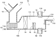
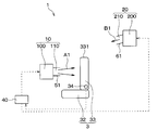
- FIGS. 10 and 11 A third embodiment will be described with reference to FIGS. 10 and 11.
- the third embodiment is the same as the first embodiment except that the configurations of the first air conditioner 10 and the second air conditioner 20 are modified with respect to the first embodiment, and the other features are the same as the first embodiment. Only the differences will be explained.
- the first air conditioning unit 100 of the first air conditioner 10 includes a face outlet 114, a foot outlet (not shown), a defroster outlet (not shown), and the like.
- An application blowout opening 117 is provided.
- a first other-use duct 54 is connected to the first other-use blowout opening 117.
- the outlet of the first other use duct 54 corresponds to the first other use outlet 540.
- the first air conditioning unit 100 and the ducts 51 and 54 may be integrated.
- the second air conditioning unit 200 of the second air conditioner 20 is provided with a second multipurpose blowout opening 216.
- a second other use duct 63 is connected to the second other use blowout opening 216.
- the outlet of the second other use duct 63 corresponds to the second other use outlet 630.
- the second air conditioning unit 200 and the ducts 61 and 63 may be integrated.
- the conditioned air blown out from the first other-purpose air outlet 540 and the second other-purpose air outlet 630 is used for applications other than the cabin air conditioning.
- the conditioned air is supplied to a battery pack 70 mounted on a vehicle, and used for temperature control of a battery (not shown) stored in the battery pack 70.
- the conditioned air blown out from the first other application outlet 540 and the second other application outlet 630 is not limited to the temperature control of the battery, and the temperature control of the temperature refrigerator mounted on the vehicle or the air in the passenger compartment It can be used for various applications such as exhaustion (ie ventilation in a car).
- the first air conditioner 10 has a first air volume adjustment unit 120 that adjusts the air volume blown out from the first outlet 110 and the air volume blown out from the first other application outlet 540.
- the first air volume adjustment unit 120 is configured of, for example, a face door 17 that opens and closes the face outlet opening 114 and a first other application door 121 that opens and closes the first other application outlet opening 117.
- the first air volume adjustment unit 120 is a rotary door or a slide door configured to close the other opening as the opening of one of the face outlet 114 and the first other application outlet 117 is opened. May be integrated.
- the second air conditioner 20 also has a second air volume adjustment unit 220 that adjusts the air volume blown out from the second air outlet 210 and the air volume blown out from the second other application air outlet 630.
- the second air volume adjustment unit 220 includes, for example, a ceiling blowout door as the second mode switching door 27 for opening and closing the ceiling blowout opening 214 and a second other use door 221 for opening and closing the second other use blowout opening 216. It is done.
- the second air volume adjustment unit 220 is also configured as a rotary door or a slide door configured to close the other of the ceiling blowout opening 214 and the second other-use blowout opening 216 as the opening is opened. May be integrated.
- the control device 40 of the third embodiment also controls the drive of the first air conditioner 10 and the second air conditioner 20 according to the position of the seat 32 as the movable portion of the front seat 3 detected by the position detection unit 30. .
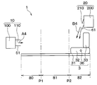
- FIG. 10 shows a state in which the seat portion 32 is positioned at the forefront in a range in which the seat portion 32 of the front seat 3 moves in the longitudinal direction of the vehicle.
- the control device 40 increases the air amount A1 blown out from the first air outlet 110 and reduces the air amount B1 blown out from the second air outlet 210. Do.
- the control device 40 reduces the air volume C1 blown out from the first other use outlet 540, and increases the air volume D1 blown out from the second other use outlet 630.
- the control device 40 drives and controls the first air volume adjustment unit 120 as the seat portion 32 of the front seat 3 approaches the first air outlet 110, so that the air volume blown out from the first air outlet 110 A1 is enlarged, and the air volume C1 blown out from the first other-purpose air outlet 540 is decreased.
- the control device 40 drives and controls the second air volume adjustment unit 220 to reduce the air volume B1 blown out from the second air outlet 210, and the air volume D1 blown out from the second other use air outlet 630. Enlarge.
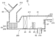
- FIG. 11 shows a state in which the seat portion 32 is located at the rearmost position in the range in which the seat portion 32 of the front seat 3 moves in the vehicle longitudinal direction.
- the control device 40 reduces the air amount A2 blown out from the first air outlet 110 and increases the air amount B2 blown out from the second air outlet 210. Do.
- the control device 40 increases the air volume C2 blown out from the first other application outlet 540, and from the second other application outlet 630 Reduce the air volume D2 to be blown out.
- the control device 40 drives and controls the first air volume adjustment unit 120 as the seat portion 32 of the front seat 3 approaches the second air outlet 210 so that the air volume blown out from the first air outlet 110 A2 is made smaller, and the air volume C2 blown out from the first other use outlet 540 is made larger.
- the control device 40 drives and controls the second air volume adjustment unit 220 to increase the air volume B2 blown out from the second air outlet 210, and the air volume D2 blown out from the second other use air outlet 630. Make it smaller.
- the first air conditioner 10 and the second air conditioner 20 can be used for various uses other than the cabin air conditioning. Then, among the first air conditioner 10 and the second air conditioner 20, the conditioned air blown out from the other-purpose air outlets 540, 630 of the air conditioner having a smaller load for air conditioning in the vehicle cabin is mainly in the vehicle cabin. Used for applications other than air conditioning. Therefore, it is possible to prevent the load from being concentrated on one of the fans 13 and 23 of either the first air conditioner 10 or the second air conditioner 20. Therefore, this air conditioning system can reduce the load of the fans 13 and 23 which the first air conditioner 10 and the second air conditioner 20 respectively have, and can extend the life.
- control device 40 controls the drive of the first air volume adjustment unit 120 so that the air volume blown out from the first outlet 110 and the air volume blown out from the first other application outlet 540 It is possible to adjust In addition, the control device 40 can adjust the amount of air blown out from the second air outlet 210 and the amount of air blown out from the second non-use air outlet 630 by controlling the drive of the second air volume adjustment unit 220. It is.
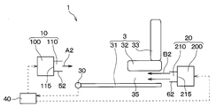
- FIGS. 12 to 14 The fourth embodiment is the same as the first embodiment except that the configurations of the outlets of the first air conditioner 10 and the second air conditioner 20 are modified with respect to the first embodiment. Only parts different from the one embodiment will be described.
- the outlet of the first foot duct 52 connected to the first foot outlet 115 provided in the first air conditioning unit 100 of the first air conditioner 10 corresponds to the first outlet 110.
- the first foot duct 52 can blow conditioned air toward the feet of the occupant seated in the front seat 3 from the first air outlet 110 provided below the instrument panel.
- the first air conditioner 10 may integrally configure the first air conditioning unit 100 and the first foot duct 52.
- the outlet of the second foot duct 62 connected to the second foot outlet 215 provided in the second air conditioning unit 200 of the second air conditioner 20 corresponds to the second outlet 210.
- the second foot duct 62 can blow conditioned air toward the feet of the occupant seated in the front seat 3 from the second air outlet 210 provided at the rear of the front seat 3.
- the 2nd air conditioner 20 may comprise the 2nd air conditioning unit 200 and the 2nd foot duct 62 in one.
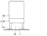
- a space 35 through which wind can pass is provided between the seat portion 32 of the front seat 3 and the floor 7 of the vehicle body. Therefore, the conditioned air blown out from the second air outlet 210 passes through the space 35 between the seat portion 32 of the front seat 3 and the floor 7 of the vehicle body and is delivered to the feet of the occupant seated in the front seat 3.
- the control device 40 of the fourth embodiment also controls the driving of the first air conditioner 10 and the second air conditioner 20 according to the position of the seat 32 of the front seat 3 detected by the position detector 30.
- FIG. 12 shows a state where the seat portion 32 is positioned at the forefront in a range in which the seat portion 32 of the front seat 3 moves in the vehicle longitudinal direction.
- the control device 40 increases the air conditioning capacity by the conditioned air blown out from the first outlet 110 as the seat 32 of the front seat 3 gets closer to the first outlet 110, and the air conditioner blown out from the second outlet 210 Reduce the air conditioning capacity by wind.
- the control device 40 increases the air amount A1 blown out from the first outlet 110, and is blown out from the second outlet 210.
- the drive of the first blower 13 and the second blower 23 is controlled so as to reduce the air volume B1.
- FIG. 13 shows a state where the seat portion 32 is located at the rearmost position in the range in which the seat portion 32 of the front seat 3 moves in the vehicle longitudinal direction.
- the control device 40 increases the air conditioning capacity by the air conditioning air blown out from the second air outlet 210 as the seat portion 32 of the front seat 3 approaches the second air outlet 210, and the air conditioning blown out from the first air outlet 110 Reduce the air conditioning capacity by wind.
- the control device 40 increases the air amount B2 blown out from the second outlet 210 and is blown out from the first outlet 110.
- the drive of the first blower 13 and the second blower 23 is controlled so as to reduce the air volume A2.
- the magnitude relationship of the air volumes is A1> A2 ⁇ 0, B2> B1 ⁇ 0. Then, the air volumes A1, A2, B1 and B2 blown out from the first air outlet 110 and the second air outlet 210 respectively sit on the front seat 3 regardless of the position of the seat portion 32 of the front seat 3
- the total air conditioning capacity supplied to the occupants is set to be substantially the same.
- the air conditioning system 1 of the fourth embodiment described above can also achieve the same effects as the first embodiment and the like in the lower body air conditioning.
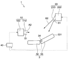
- the fifth embodiment will be described with reference to FIGS.
- a part of the control method of the first air conditioner 10 and the second air conditioner 20 is modified with respect to the first embodiment, and the others are similar to the first embodiment. Only the differences from the first embodiment will be described.
- the position detection unit 30, the control device 40, and the like are not shown.
- the outlet of the face duct 51 corresponds to the first outlet 110.
- the outlet of the ceiling duct 61 corresponds to the second outlet 210.
- the control device 40 of the fifth embodiment also controls the driving of the first air conditioner 10 and the second air conditioner 20 according to the position of the seat 32 as the movable portion of the front seat 3 detected by the position detection unit 30. .
- the distance between the first outlet 110 and the second outlet 210 is assumed to be relatively large. In this case, when the seat portion 32 of the front seat 3 is in the vicinity of the foremost part, the air blowing from the second air outlet 210 may hardly affect the air conditioning feeling of the occupant sitting on the front seat 3. In addition, when the seat portion 32 of the front seat 3 is near the rear end, the air blowing from the first air outlet 110 may hardly affect the air conditioning feeling of the occupant sitting on the front seat 3. Therefore, the control device 40 divides the range in which the seat portion 32 moves in the vehicle longitudinal direction into the front area 80, the middle area 81, and the rear area 83, and performs different control in each area.
- the front area 80 refers to an area between the foremost portion and the first reference position P1.
- the intermediate area 81 refers to an area between the first reference position P1 and the second reference position P2.
- the rear area 83 refers to an area between the second reference position P2 and the rearmost portion.
- the first reference position P1 and the second reference position P2 can be arbitrarily set by experiment or the like. For example, when the seat portion 32 of the front seat 3 is in front of that position, the first reference position P1 hardly affects the feeling of air conditioning of the occupant seated in the front seat 3 by the air flow from the second outlet 210 It is set as a position. Also, for example, when the seat portion 32 of the front seat 3 is behind the position of the second reference position P2, the air flow from the first outlet 110 almost affects the air conditioning feeling of the occupant sitting on the front seat 3. It is set as a position to stop giving.
- the air volume blown out from the first air outlet 110 is A1
- the air volume blown out from the second air outlet 210 is Assume B1.
- the air volume blown out from the first outlet 110 is A2
- the second outlet 210 Let B2 be the amount of air blown out.
- the air volume blown out from the first outlet 110 is A3.
- B3 be the amount of air blown out.
- the air volume blown out from the first air outlet 110 is A4, and the air volume blown out from the second air outlet 210 is B4.
- the magnitude relationship between the air volumes blown out from the first air outlet 110 and the second air outlet 210 is A4 ⁇ A1 ⁇ A2> A3> A4 and B4 ⁇ B1 ⁇ B2> B3> B4.
- control of the control device 40 when the center 36 of the seat portion 32 of the front seat 3 is in the front area 80 will be described with reference to FIGS. 15 and 16.
- the control device 40 increases the air volumes A1 and A2 blown out from the first air outlet 110 as the seat portion 32 is farther from the first air outlet 110.
- the air volume of the second air outlet 210 is gradually increased from the minimum B1 and B2.
- the control device 40 reduces the air volumes A2 and A1 blown out from the first outlet 110.
- the air volumes B2 and B1 of the second air outlet 210 are also gradually reduced.
- Control of the control device 40 when the center 36 of the seat portion 32 of the front seat 3 is in the middle area 81 will be described with reference to FIGS. 16 and 17.
- the control device 40 reduces the air volumes A2 and A3 blown out from the first air outlet 110 and blows it out from the second air outlet 210.
- Air volume B2 and B3 are increased.
- the control device 40 increases the air volumes A3 and A2 blown out from the first outlet 110 as the seat 32 of the front seat 3 approaches the first outlet 110, and then blown out from the second outlet 210 Reduce the air volume B3 and B2. That is, in the fifth embodiment, when the center 36 of the seat portion 32 of the front seat 3 is in the middle area 81, the same control as that in the first embodiment and the like is performed.
- control device 40 increases the air volumes B4 and B3 blown out from the second air outlet 210 as the seat portion 32 is farther from the second air outlet 210. At this time, the air volumes A4 and A3 of the first air outlet 110 are gradually increased from the minimum. In other words, as the seat portion 32 approaches the second air outlet 210, the control device 40 reduces the air volumes B3 and B4 blown out from the second air outlet 210. At this time, the air volumes A3 and A4 of the first air outlet 110 are also gradually reduced.
- the load of the air conditioners 10 and 20 is controlled by performing the same control as in the first embodiment. While reducing, it can improve the comfort of the occupant.
- the conditioned air blown out from the first air outlet 110 can be mainly used to enhance the comfort of the occupant.
- the conditioned air blown out from the second air outlet 210 can be mainly used to enhance the comfort of the occupant.
- control device adjusts the air volume blown out from the first and second outlets according to the position or the angle of the movable portion of the front seat, but the invention is not limited thereto.
- control device may adjust the temperature and humidity of the conditioned air blown out from the first and second outlets according to the position or angle of the movable part of the front seat.
- the air volume adjustment unit for adjusting the air volume blown out from each air outlet is provided in each air conditioning unit, but the present invention is not limited thereto.
- the air flow rate adjustment unit may be provided in a duct connected to each air conditioning unit.
- the air conditioning system has been described as being mounted on a two-row vehicle equipped with a front seat and a rear seat, but the invention is not limited thereto. In other embodiments, the air conditioning system may be mounted on a single row seat vehicle or a triple row seat vehicle.
- an air conditioning system mounted on a vehicle including a front seat having at least a movable portion movable in the longitudinal direction of the vehicle is: A first air conditioner, a second air conditioner, a position detector, and a controller are provided.
- the first air conditioner has a first blower for blowing the conditioned air, and a first outlet for blowing the conditioned air blown by the first blower from the front of the vehicle to the occupant seated in the front seat.
- the second air conditioner has a second blower for blowing the conditioned air, and a second outlet for blowing the conditioned air blown by the second blower from the rear of the vehicle to the occupant seated in the front seat.
- the position detection unit detects the position or angle of the movable portion of the front seat.
- the control device controls the driving of the first air conditioner and the second air conditioner in accordance with the position or the angle of the movable portion detected by the position detection unit.
- the control device increases the air conditioning capability by the air conditioning wind blown out from the first outlet as the movable portion approaches the first outlet in the whole area or a part of the range in which the movable portion moves in the vehicle longitudinal direction. And reduce the air conditioning capacity by the air conditioning air blown out from the second air outlet.
- the control device increases the air conditioning capacity by the air conditioning air blown out from the second air outlet as the movable part approaches the second air outlet, and reduces the air conditioning capacity by the air conditioning air blown out from the first air outlet. .
- control device increases the air volume blown out from the first air outlet as the movable part approaches the first air outlet, and reduces the air volume blown out from the second air outlet. Further, the control device increases the amount of air blown out from the second outlet as the movable part approaches the second outlet, and reduces the amount of air blown out from the first outlet.
- the load of each fan can be reduced by distributing the load to both fans without concentrating the load on any one of the first fan and the second fan.
- the amount of air blown out from the blowout port closer to the movable portion of the front seat among the first blowout port and the second blowout port is increased, the occupant is given a strong feeling of wind speed with punching power. Can.
- the conditioned air blown out from the first and second air outlets collide with each other and stay in the vicinity of the occupant, it becomes possible to efficiently perform air conditioning in the vicinity of the occupant. Therefore, this air conditioning system can reduce the load on the blowers of the individual air conditioners and can enhance the comfort of the occupant.
- the control device increases the air volume blown out from the first air outlet as the movable part approaches the first air outlet, and reduces the air volume blown out from the second air outlet.
- the driving of the first fan and the second fan is controlled.
- the control device increases the amount of air blown out from the second outlet as the movable part approaches the second outlet, and reduces the amount of air blown out from the first outlet and the first blower and the second fan. Control the drive of the blower. According to this, the load of each fan can be reduced by distributing the load to both fans without concentrating the load on any one of the first fan and the second fan.
- the first air conditioner further includes a first other-purpose air outlet that is used for applications other than in-vehicle air conditioning.
- the second air conditioner further includes a second other-purpose air outlet used for applications other than in-vehicle air conditioning.
- the control device increases the air volume blown out from the first air outlet as the movable part approaches the first air outlet, and reduces the air volume blown out from the first other application air outlet, and from the second air outlet Reduce the amount of air blown out and increase the amount of air blown out from the second all-purpose air outlet.
- control device reduces the amount of air blown out from the first outlet as the movable part approaches the second outlet, and increases the amount of air blown out from the first other application outlet, and the second blow The amount of air blown out from the outlet is increased, and the amount of air blown out from the second other use outlet is reduced.
- the conditioned air blown out from the other-purpose air outlet of the air conditioner having a smaller load for air conditioning the vehicle interior is used for applications other than air conditioning in the vehicle interior Mainly used. Therefore, it is possible to prevent the load from being concentrated on one fan of the first air conditioner and the second air conditioner, and it is possible to reduce the load of the fan that each air conditioner has.
- the first air conditioner further includes a first air volume adjustment unit that adjusts the air volume blown out from the first outlet and the air volume blown out from the first other application outlet.
- the second air conditioner further includes a second air volume adjustment unit that adjusts the air volume blown out from the second air outlet and the air volume blown out from the second other use air outlet.
- the control device increases the amount of air blown out from the first outlet as the movable part approaches the first outlet, and reduces the amount of air blown out from the outlet for the other first use.
- Drive control controls the drive of the second air volume adjustment unit so as to reduce the air volume blown out from the second air outlet and increase the air volume blown out from the second other application air outlet.
- control device reduces the amount of air blown out from the first outlet as the movable part approaches the second outlet, and adjusts the amount of first air so as to increase the amount of air blown out from the first other application outlet.
- Drive control of the unit At that time, the control device controls the drive of the second air volume adjustment unit so as to increase the air volume blown out from the second air outlet and to decrease the air volume blown out from the second other use air outlet.
- control device can adjust the air volume blown out from the first outlet and the air volume blown out from the first other application outlet by controlling the drive of the first air volume adjustment unit. is there.
- control device can adjust the amount of air blown out from the second outlet and the amount of air blown out from the second other-purpose outlet by controlling the drive of the second air amount adjusting unit.
- the conditioned air blown out from the first other use outlet and the second other use outlet is temperature control of the battery mounted on the vehicle, temperature control of the heating refrigerator, or air in the passenger compartment. Used for any of the discharges of According to this, it is possible to use the 1st air conditioner and the 2nd air conditioner for various uses other than car interior air conditioning.
- a range in which the movable portion moves in the vehicle longitudinal direction is a front region between the foremost portion and a predetermined first reference position, and a second reference position and a rear portion behind the first reference position. , And an intermediate region between the first reference position and the second reference position.
- the control device performs control of at least one of the above-described first to fifth aspects when the movable portion is in the intermediate region. Then, when the movable portion is in the front area, the control device increases the amount of air blown from the first air outlet as the movable portion is farther from the first air outlet. In addition, when the movable part is in the rear region, the amount of air blown out from the second air outlet is increased as the movable part is farther from the second air outlet.
- the air conditioning of the passenger whose air is blown from the second outlet is seated on the front seat
- it has little effect on the feeling.
- the air blowing from the first air outlet may hardly affect the air conditioning feeling of the occupant seated in the front seat. Therefore, when the movable portion of the front seat is in the front area, the conditioned air blown out from the first air outlet can be mainly used to enhance the comfort of the occupant.
- the conditioned air blown out from the second air outlet can be mainly used to enhance the comfort of the occupant.
- the control of at least one of the first to fifth aspects described above is performed to reduce the load on the air conditioner and to reduce the occupant's load. You can enhance the sense of comfort.
Landscapes
- Physics & Mathematics (AREA)
- Thermal Sciences (AREA)
- Engineering & Computer Science (AREA)
- Mechanical Engineering (AREA)
- Air-Conditioning For Vehicles (AREA)
Applications Claiming Priority (2)
| Application Number | Priority Date | Filing Date | Title |
|---|---|---|---|
| JP2017222195A JP2019093766A (ja) | 2017-11-17 | 2017-11-17 | 空調システム |
| JP2017-222195 | 2017-11-17 |
Publications (1)
| Publication Number | Publication Date |
|---|---|
| WO2019097914A1 true WO2019097914A1 (ja) | 2019-05-23 |
Family
ID=66539741
Family Applications (1)
| Application Number | Title | Priority Date | Filing Date |
|---|---|---|---|
| PCT/JP2018/037971 Ceased WO2019097914A1 (ja) | 2017-11-17 | 2018-10-11 | 空調システム |
Country Status (2)
| Country | Link |
|---|---|
| JP (1) | JP2019093766A (enExample) |
| WO (1) | WO2019097914A1 (enExample) |
Cited By (1)
| Publication number | Priority date | Publication date | Assignee | Title |
|---|---|---|---|---|
| WO2022230873A1 (ja) * | 2021-04-28 | 2022-11-03 | テイ・エス テック株式会社 | 温度調節システム |
Families Citing this family (1)
| Publication number | Priority date | Publication date | Assignee | Title |
|---|---|---|---|---|
| JP6958276B2 (ja) * | 2017-11-17 | 2021-11-02 | 株式会社デンソー | 空調システム |
Citations (4)
| Publication number | Priority date | Publication date | Assignee | Title |
|---|---|---|---|---|
| JPH1086628A (ja) * | 1996-09-12 | 1998-04-07 | Mitsubishi Heavy Ind Ltd | 車両用空気調和装置 |
| JPH11189023A (ja) * | 1997-12-26 | 1999-07-13 | Nissan Motor Co Ltd | 車両用空調装置 |
| JP2002046445A (ja) * | 2000-08-04 | 2002-02-12 | Denso Corp | 車両用空調装置およびその制御方法 |
| JP2006264485A (ja) * | 2005-03-23 | 2006-10-05 | Denso Corp | 車両用空調装置 |
Family Cites Families (2)
| Publication number | Priority date | Publication date | Assignee | Title |
|---|---|---|---|---|
| JP3415205B2 (ja) * | 1993-07-20 | 2003-06-09 | マツダ株式会社 | 車両用空調装置 |
| JP4351579B2 (ja) * | 2004-05-12 | 2009-10-28 | 本田技研工業株式会社 | 車両用シート装置 |
-
2017
- 2017-11-17 JP JP2017222195A patent/JP2019093766A/ja active Pending
-
2018
- 2018-10-11 WO PCT/JP2018/037971 patent/WO2019097914A1/ja not_active Ceased
Patent Citations (4)
| Publication number | Priority date | Publication date | Assignee | Title |
|---|---|---|---|---|
| JPH1086628A (ja) * | 1996-09-12 | 1998-04-07 | Mitsubishi Heavy Ind Ltd | 車両用空気調和装置 |
| JPH11189023A (ja) * | 1997-12-26 | 1999-07-13 | Nissan Motor Co Ltd | 車両用空調装置 |
| JP2002046445A (ja) * | 2000-08-04 | 2002-02-12 | Denso Corp | 車両用空調装置およびその制御方法 |
| JP2006264485A (ja) * | 2005-03-23 | 2006-10-05 | Denso Corp | 車両用空調装置 |
Cited By (2)
| Publication number | Priority date | Publication date | Assignee | Title |
|---|---|---|---|---|
| WO2022230873A1 (ja) * | 2021-04-28 | 2022-11-03 | テイ・エス テック株式会社 | 温度調節システム |
| JP7545097B2 (ja) | 2021-04-28 | 2024-09-04 | テイ・エス テック株式会社 | 温度調節システム |
Also Published As
| Publication number | Publication date |
|---|---|
| JP2019093766A (ja) | 2019-06-20 |
Similar Documents
| Publication | Publication Date | Title |
|---|---|---|
| JP4224939B2 (ja) | 車両用空調装置 | |
| JP5594281B2 (ja) | 車両用空調装置 | |
| JP5128977B2 (ja) | 自動車用空気調和装置 | |
| JP5706923B2 (ja) | 車両用空気調和装置 | |
| JP6370083B2 (ja) | 車両用空調装置 | |
| US20170267065A1 (en) | Air conditioning system for vehicle | |
| JP6558490B2 (ja) | 車両用空調装置 | |
| JP2012111318A (ja) | 車両用空調装置 | |
| JP2012001200A (ja) | 車両用空調装置 | |
| WO2020026634A1 (ja) | 車両用空気調和装置 | |
| JP2009202687A (ja) | 車両用空調装置 | |
| JP2014141236A (ja) | 車両用空気調和システム | |
| JP6627976B2 (ja) | 車両用空調装置 | |
| WO2019097914A1 (ja) | 空調システム | |
| CN103260916A (zh) | 车辆用空调系统 | |
| JP2008302793A (ja) | 車両用空調装置 | |
| WO2021075258A1 (ja) | 車両用空調システム | |
| KR101627733B1 (ko) | 차량용 공조장치 | |
| JP6958276B2 (ja) | 空調システム | |
| JP5458663B2 (ja) | 車両用空調装置 | |
| JP2008149998A (ja) | 車両用空調装置 | |
| WO2014103610A1 (ja) | 車両用空気調和システム | |
| KR101767038B1 (ko) | 차량용 공기조화 시스템 | |
| JP2014196028A (ja) | 車両用空気調和システム | |
| JP7010793B2 (ja) | 車両用空調装置及びそれを用いた空調制御方法 |
Legal Events
| Date | Code | Title | Description |
|---|---|---|---|
| 121 | Ep: the epo has been informed by wipo that ep was designated in this application |
Ref document number: 18879612 Country of ref document: EP Kind code of ref document: A1 |
|
| NENP | Non-entry into the national phase |
Ref country code: DE |
|
| 122 | Ep: pct application non-entry in european phase |
Ref document number: 18879612 Country of ref document: EP Kind code of ref document: A1 |