WO2019097914A1 - Air conditioning system - Google Patents
Air conditioning system Download PDFInfo
- Publication number
- WO2019097914A1 WO2019097914A1 PCT/JP2018/037971 JP2018037971W WO2019097914A1 WO 2019097914 A1 WO2019097914 A1 WO 2019097914A1 JP 2018037971 W JP2018037971 W JP 2018037971W WO 2019097914 A1 WO2019097914 A1 WO 2019097914A1
- Authority
- WO
- WIPO (PCT)
- Prior art keywords
- air
- outlet
- blown out
- air conditioning
- amount
- Prior art date
Links
Images


Classifications
-
- B—PERFORMING OPERATIONS; TRANSPORTING
- B60—VEHICLES IN GENERAL
- B60H—ARRANGEMENTS OF HEATING, COOLING, VENTILATING OR OTHER AIR-TREATING DEVICES SPECIALLY ADAPTED FOR PASSENGER OR GOODS SPACES OF VEHICLES
- B60H1/00—Heating, cooling or ventilating [HVAC] devices
-
- B—PERFORMING OPERATIONS; TRANSPORTING
- B60—VEHICLES IN GENERAL
- B60H—ARRANGEMENTS OF HEATING, COOLING, VENTILATING OR OTHER AIR-TREATING DEVICES SPECIALLY ADAPTED FOR PASSENGER OR GOODS SPACES OF VEHICLES
- B60H1/00—Heating, cooling or ventilating [HVAC] devices
- B60H1/32—Cooling devices
-
- B—PERFORMING OPERATIONS; TRANSPORTING
- B60—VEHICLES IN GENERAL
- B60H—ARRANGEMENTS OF HEATING, COOLING, VENTILATING OR OTHER AIR-TREATING DEVICES SPECIALLY ADAPTED FOR PASSENGER OR GOODS SPACES OF VEHICLES
- B60H1/00—Heating, cooling or ventilating [HVAC] devices
- B60H1/34—Nozzles; Air-diffusers
Definitions
- the present disclosure relates to an air conditioning system for a vehicle.
- an air conditioning system for air conditioning a vehicle interior is known.
- the air conditioning system described in Patent Document 1 adjusts the air volume of conditioned air blown out from an outlet provided in an instrument panel according to the position of a front seat moving in the longitudinal direction of the vehicle. Specifically, the air conditioning system reduces the amount of air blown out from the outlet as the position of the front seat approaches the outlet, and the amount of air blown out from the outlet as the position of the front seat moves farther from the outlet. Increase the Thus, the air conditioning system provides a certain degree of air conditioning to the occupant seated in the front seat.
- the air conditioning system described in Patent Document 1 requires a large amount of air when the position of the front seat is far from the air outlet, so the load of the blower and the compressor that constitutes the refrigeration cycle of the air conditioner becomes large. Therefore, the life of the air conditioner may be shortened. Further, in the air conditioning system, when the position of the front seat is far from the air outlet, the air conditioned air blown out from the air outlet diffuses before reaching the occupant. As a result, since the occupant can not be given a strong feeling of air conditioning having a punching power, there is a concern that the occupant may feel a lack of objectivity.
- the present disclosure aims to provide an air conditioning system capable of reducing the load on the air conditioner and enhancing the comfort of the occupant.
- an air conditioning system mounted on a vehicle including a front seat having at least a portion of a movable portion movable in the longitudinal direction of the vehicle, A first air blower having a first air blower for blowing air conditioning air, and a first air outlet having a first air outlet blowing out air conditioning air blown by the first air blower from a front of the vehicle to an occupant seated in a front seat; A second air blower having a second blower for blowing the air conditioning air, and a second air outlet for blowing the air conditioning air blown by the second blower from the rear of the vehicle to an occupant seated in the front seat; A position detection unit that detects the position or angle of the movable unit of the front seat; A control device that controls driving of the first air conditioner and the second air conditioner according to the position or angle of the movable part detected by the position detection unit; The controller is In all or part of the range in which the movable part moves in the longitudinal direction of the vehicle, As the
- the air conditioning capacity by the air conditioning wind blown out from the blowout port closer to the movable portion of the front seat among the first blowout port and the second blowout port is increased, the air conditioning having a so-called punch power is strong Can give a feeling.
- the conditioned air blown out from each of the first and second outlets collides with each other in the vicinity of the occupant, so that the conditioned air can be retained in the vicinity of the occupant. Therefore, compared with the case where the air is blown from any one of the first and second air outlets, the diffusion of the conditioned air is suppressed, so that the area near the occupant can be efficiently air-conditioned. Therefore, this air conditioning system can reduce the load on the individual air conditioners and enhance the comfort of the occupant.
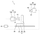
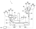
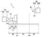
- the air conditioning system 1 of the present embodiment is mounted on the vehicle 2 and blows out conditioned air whose temperature and humidity are adjusted according to a predetermined air conditioning mode from a plurality of outlets into the vehicle compartment, thereby performing air conditioning of the vehicle interior. It is a thing.
- the vehicle 2 includes a front seat 3 and a rear seat 4.
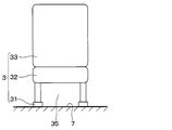
- the front seat 3 has a rail 31 extending in the front-rear direction of the vehicle, and a seat 32 and a backrest 33 movable on the rail 31.
- the seat portion 32 of the front seat 3 corresponds to a movable portion movable in the longitudinal direction of the vehicle.
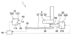
- the air conditioning system 1 includes a first air conditioner 10, a second air conditioner 20, a position detection unit 30, a control device 40, and the like.
- the first air conditioner 10 is provided inside the instrument panel 5.
- the first air conditioner 10 generates a first air conditioning unit 100 that generates conditioned air and a first blow that blows out the conditioned air generated by the first air conditioning unit 100 from the front of the vehicle to the occupant 6 seated on the front seat 3. It has an outlet 110.
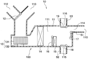
- FIG. 4 is a schematic view of the first air conditioner 10.
- the first air conditioner 10 includes a first air conditioning unit 100 and a plurality of ducts 51, 52, 53.
- the outlet of the face duct 51 corresponds to the first outlet 110 described above.
- the face duct 51 can blow conditioned air toward the upper body or the periphery of the occupant 6 seated on the front seat 3 from the first outlet 110 provided in the instrument panel 5.
- the first air conditioner 10 may integrally configure the first air conditioning unit 100 and the plurality of ducts 51, 52, 53. Alternatively, the conditioned air may be directly blown out from the blowout openings 114, 115, 116 of the first air conditioner 10.
- the configuration of the first air conditioning unit 100 will be described.
- the first air conditioning unit 100 includes an inside / outside air switching door 12, a blower 13, an evaporator 14, a heater core 15, an air mixing door 16, mode switching doors 17, 18, 19 and the like inside the air conditioning case 11.
- the air conditioning case 11 introduces outside air into the air flow passage 111 from the outside of the vehicle and the inside air introduction port 112 for introducing the air into the air flow passage 111 from a predetermined location in the vehicle room on the air flow direction upstream side of the air flow passage 111 It has an outside air introduction port 113 for.
- the inside / outside air switching door 12 continuously adjusts the opening area of the inside air introduction port 112 and the opening area of the outside air introduction port 113.
- the inside / outside air switching door 12 rotates so as to close the other opening as the opening of one of the inside air introduction port 112 and the outside air introduction port 113 is opened.
- the inside / outside air switching door 12 can adjust the ratio of the air volume of the inside air introduced into the ventilation path 111 and the air volume of the outside air.
- the blower 13 is composed of a centrifugal fan 131, a motor 132 for rotationally driving the centrifugal fan 131, and the like.
- the centrifugal fan 131 rotates with the drive of the motor 132, air is blown to the air passage 111.
- inside air or outside air is introduced into the ventilation path 111 from the inside air introduction port 112 or the outside air introduction port 113.
- the temperature and humidity of the air blown by the blower 13 and flowing through the ventilation path 111 are adjusted by the evaporator 14 and the heater core 15, and any of the plurality of blowout openings 114, 115, 116 communicating with the ventilation path 111 It is blown out into the passenger compartment.
- the evaporator 14 is a heat exchanger for cooling the air flowing through the air passage 111.
- the evaporator 14 constitutes a known refrigeration cycle together with a compressor, a condenser, an expansion valve and the like which are not shown.
- the refrigerant in a gas-liquid two-layer state flows through a tube (not shown) of the evaporator 14.
- the evaporator 14 cools the air flowing through the air passage 111 by the latent heat of evaporation of the refrigerant flowing inside the tube.
- the heater core 15 is a heat exchanger for heating the air flowing through the air passage 111. Hot water or the like flows inside the tube (not shown) of the heater core 15. The heater core 15 heats the air flowing through the air passage 111 by heat exchange between the warm water flowing inside the tube and the air flowing through the air passage 111.
- An air mix door 16 is provided between the evaporator 14 and the heater core 15.
- the air mix door 16 adjusts the ratio of the air volume flowing around the heater core 15 after passing through the evaporator 14 and the air volume passing through the heater core 15 after passing through the evaporator 14.
- the air conditioning case 11 has, on the downstream side in the air flow direction of the air passage 111, a plurality of blowout openings 114, 115, 116 for blowing air from the air passage 111 into the vehicle compartment.
- the plurality of blowout openings 114, 115, 116 are configured by, for example, a face blowout opening 114, a foot blowout opening 115, a defroster blowout opening 116, and the like.
- the face blowout opening 114 blows the conditioned air toward the upper body of the occupant 6 seated in the front seat 3 or the periphery thereof.
- the foot blowout opening 115 blows the conditioned air toward the feet of the occupant 6.
- the defroster blowout opening 116 blows the conditioned air toward the windshield of the vehicle 2.
- the face blowing opening 114, the foot blowing opening 115, and the defroster blowing opening 116 are provided with mode switching doors 17, 18 and 19 for opening and closing the respective openings.
- the mode switching doors 17, 18, 19 are configured by the face door 17, the foot door 18 and the defroster door 19.
- the face door 17 opens and closes the face blowout opening 114.
- the foot door 18 opens and closes the foot outlet opening 115.
- the defroster door 19 opens and closes the defroster blowout opening 116.
- the inside / outside air switching door 12, the air mix door 16, the face door 17, the foot door 18, and the defroster door 19 described above are each driven by an actuator such as a servomotor (not shown).
- a plurality of ducts 51, 52, 53 configured as separate members from the air conditioning case 11 are connected to the plurality of air outlet openings 114, 115, 116 of the air conditioning case 11 of the first air conditioning unit 100, respectively.
- the plurality of ducts 51, 52, 53 are constituted by, for example, the face duct 51, the foot duct 52, the defroster duct 53, and the like.
- the face duct 51 is connected to the face outlet 114.
- the foot duct 52 is connected to the foot outlet opening 115.
- the defroster duct 53 is connected to the defroster blowout opening 116.
- the second air conditioner 20 generates a second air conditioning unit 200 that generates conditioned air, and a second outlet that blows out the conditioned air generated by the second air conditioning unit 200 from the rear of the vehicle to the occupant 6 who sits on the front seat 3 It has 210.
- the second air conditioning unit 200 is installed on the vehicle ceiling in FIGS. 1 to 3, the position at which the second air conditioning unit 200 is installed is not limited to this.
- the second air conditioning unit 200 can be installed at any place, such as the vehicle ceiling, the rear of the rear seat 4, or the side of the rear seat 4, for example.
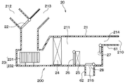
- FIG. 5 is a schematic view of the second air conditioner 20.
- the second air conditioner 20 includes a second air conditioning unit 200 and a plurality of ducts 61 and 62.
- the second air conditioning unit 200 also includes an inside / outside air switching door 22, a blower 23, an evaporator 24, a heater core 25, an air mix door 26, a mode switching door 27, 28 and the like inside the air conditioning case 21. Is equipped.
- the blower 23 is composed of a centrifugal fan 231, a motor 232 for rotationally driving the centrifugal fan 231, and the like.
- a ceiling outlet opening 214 and a foot outlet opening 215 are provided on the downstream side of the air passage 211 of the air conditioning case 21 of the second air conditioning unit 200, and no defroster outlet is provided.
- a ceiling duct 61 is connected to the ceiling blowout opening 214 provided in the air conditioning case 21 of the second air conditioning unit 200.
- the outlet of the ceiling duct 61 corresponds to the second outlet 210 described above.
- the ceiling duct 61 can blow conditioned air toward the upper body or the periphery of the occupant 6 seated on the front seat 3 from the second air outlet 210 provided in the vehicle ceiling.
- the second air conditioner 20 may also integrally configure the second air conditioning unit 200 and the plurality of ducts 61 and 62. Alternatively, the conditioned air may be directly blown out from the blowout openings 214 and 215 of the second air conditioner 20.
- the respective components included in the first air conditioning unit 100 are appropriately referred to as the first air conditioning case 11, the first inside / outside air switching door 12, the first blower 13, the first evaporator 14, the first heater core 15, the first air It may be called the mix door 16 and the first mode switching door 17, 18, 19.
- each configuration of the second air conditioning unit 200 may be appropriately determined by the second air conditioning case 21, the second inside / outside air switching door 22, the second blower 23, the second evaporator 24, the second heater core 25, the second air mix door 26. And the second mode switching door 27, 28.
- the air conditioning system 1 drives the first air conditioner 10 and the second air conditioner 20 according to the position of the seat 32 as the movable portion of the front seat 3.
- the control device 40 controls the position of the seat portion 32 of the front seat 3 and the position detection unit 30 according to the position of the seat 32 as the movable portion of the front seat 3.
- the position of the seat portion 32 of the front seat 3 is detected by the position detection unit 30.
- the position information of the seat portion 32 of the front seat 3 detected by the position detection unit 30 is transmitted to the control device 40.
- the control device 40 is configured by a computer having a processor, a memory, and the like, and peripheral circuits thereof.
- the memory of the control device 40 is configured of a non-transitional tangible storage medium.
- the first air conditioner 10 and the second air conditioner 20 are described as being driven and controlled by one control device 40 in FIGS. 1 to 3, the number and arrangement of the control devices 40 are the same. Not limited to.
- the first air conditioner 10 and the second air conditioner 20 may be drive-controlled by separate control devices.
- the control device 40 controls the driving of the first air conditioner 10 and the second air conditioner 20 according to the position of the seat portion 32 of the front seat 3 detected by the position detection unit 30.
- the control device 40 controls the driving of the first air conditioner 10 and the second air conditioner 20 in the whole area or a part of the range in which the seat portion 32 of the front seat 3 moves in the vehicle longitudinal direction.
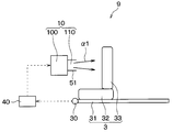
- FIG. 2 shows a state where the seat portion 32 is positioned at the forefront in a range in which the seat portion 32 of the front seat 3 moves in the longitudinal direction of the vehicle.
- the control device 40 increases the air conditioning capacity by the conditioned air blown out from the first outlet 110 as the seat 32 of the front seat 3 gets closer to the first outlet 110, and the air conditioner blown out from the second outlet 210
- the air conditioning capacity of the second air conditioner 20 by wind is reduced.
- the control device 40 increases the amount of air blown from the first air outlet 110 as the seat portion 32 of the front seat 3 approaches the first air outlet 110, and blows the air from the second air outlet 210.
- the drive of the first blower 13 and the second blower 23 is controlled so as to reduce the air volume.
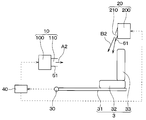
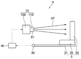
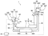
- FIG. 3 shows a state in which the seat portion 32 is located at the rearmost position in the range in which the seat portion 32 of the front seat 3 moves in the vehicle longitudinal direction.
- the control device 40 increases the air conditioning capacity by the air conditioning air blown out from the second air outlet 210 as the seat portion 32 of the front seat 3 approaches the second air outlet 210, and the air conditioning blown out from the first air outlet 110 Reduce the air conditioning capacity by wind.
- the control device 40 increases the amount of air blown from the second air outlet 210 as the seat 32 of the front seat 3 approaches the second air outlet 210 and blows the air from the first air outlet 110
- the drive of the first blower 13 and the second blower 23 is controlled so as to reduce the air volume.
- the control device 40 automatically adjusts the vertical angle of the air-conditioning air blown from the second air outlet 210 according to the position of the seat portion 32 of the front seat 3 in the blowing direction.
- the total air conditioning capacity supplied to the occupant 6 is set to be substantially the same.
- the rate of change of the air volume blown out from the first and second air outlets 110 and 210 is not limited to direct proportion, and the occupant 6 can obtain the optimum air conditioning effect at each position of the front seat 3 It is possible to set appropriately by experiment etc.
- the air conditioning system 9 of the comparative example is shown in FIGS. 6 and 7 in order to compare with the first embodiment described above.
- the air conditioning system 9 of the comparative example is configured such that only the amount of air blown out from the first air outlet 110 of the first air conditioner 10 is controlled according to the position of the seat portion 32 of the front seat 3. Specifically, the control device 40 of the comparative example reduces the amount of air blown out from the first outlet 110 as the position of the front seat 3 approaches the outlet, and the position of the front seat 3 moves farther from the outlet. The amount of air blown from the first air outlet 110 is increased. Also in the comparative example, the first outlet 110 is provided in the instrument panel 5.
- the maximum air volume A1 blown out from the first air outlet 110 is smaller than that of the comparative example by the amount of air conditioning assistance effect by the air volume B1 blown out from the second air outlet 210 It is possible.
- the maximum air volume B2 blown out from the second air outlet 210 can also be smaller than the air volume of the comparative example for the same reason. Therefore, in the first embodiment, the maximum air volumes A1 and B2 of the first air conditioner 10 and the second air conditioner 20 can be made smaller than in the comparative example.
- the air volume A1 blown out from the first air outlet 110 is blown out from the first air outlet 110 of the comparative example. It becomes almost the same as the air volume ⁇ 1. Further, when the air volume A2 blown out from the first air outlet 110 is 0, the air volume B2 blown out from the second air outlet 210 is substantially the same as the air amount ⁇ 1 blown out from the first air outlet 110 of the comparative example. .
- the air conditioning system 1 of the first embodiment described above has the following effects. (1) In the first embodiment, it is possible to perform air conditioning on the occupant 6 seated in the front seat 3 by the conditioned air blown out from the first outlet 110 and the conditioned air blown out from the second outlet 210 It is. Therefore, by distributing the load to both the first air conditioner 10 and the second air conditioner 20, the load of each air conditioner can be reduced. Specifically, it is possible to reduce the load of the first fan 13 included in the first air conditioner 10 and the load of the second fan 23 included in the second air conditioner 20. Moreover, it is also possible to reduce the load of the compressor which the 1st air conditioner 10 and the 2nd air conditioner 20 are equipped with which is not shown in figure. Therefore, the air conditioning system 1 can extend the life of the first air conditioner 10 and the second air conditioner 20.
- the amount of air blown out from the blowout port closer to the seat portion 32 of the front seat 3 out of the first blowout port 110 and the second blowout port 210 is increased. It is possible to give the occupant 6 seated at 3 a strong feeling of wind speed with so-called punching power.
- the conditioned air blown out from the first outlet 110 and the second outlet 210 collides with each other in the vicinity of the occupant, and in the vicinity of the occupant 6 seated in the front seat 3. The effect of staying is obtained. Therefore, compared with the case where the air is blown from any one of the first air outlet 110 and the second air outlet 210, the diffusion of the conditioned air is suppressed, so it is possible to efficiently perform air conditioning in the vicinity of the occupant. Therefore, the air conditioning system 1 can reduce the load of the individual air conditioners and enhance the comfort of the occupant 6.
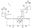
- Second Embodiment A second embodiment will be described with reference to FIGS. 8 and 9.
- the second embodiment is the same as the first embodiment except that the configuration of the movable portion of the front seat 3 is changed from the first embodiment, and therefore only the parts different from the first embodiment are different. explain.
- the front seat 3 of the second embodiment has a seat 32 and a backrest 33.
- the backrest 33 of the front seat 3 corresponds to a movable portion movable in the longitudinal direction of the vehicle.
- the angle of the backrest 33 of the front seat 3 is detected by the backrest detection unit 34.
- the backrest detection unit 34 of the second embodiment corresponds to an example of the position detection unit 30 that detects the position of the movable portion of the front seat 3.
- Information on the angle of the backrest 33 detected by the backrest detection unit 34 is transmitted to the control device 40.
- the control device 40 controls the driving of the first air conditioner 10 and the second air conditioner 20 according to the angle of the backrest 33 of the front seat 3 detected by the backrest detection unit 34.
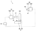
- FIG. 8 shows a state in which the head-side portion 331 of the backrest 33 is located at the foremost position in the range in which the head-side portion 331 of the backrest 33 of the front seat 3 moves in the vehicle longitudinal direction.
- the angle of the backrest 33 shows a state close to upright.
- the control device 40 increases the air conditioning capacity by the air conditioning air blown out from the first air outlet 110 as the part 331 on the head side of the backrest 33 approaches the first air outlet 110 in the vehicle longitudinal direction, and the second blowing The air conditioning capacity by the air conditioning wind blown out from the outlet 210 is reduced.
- control device 40 increases the air volume A1 blown out from the first air outlet 110 as the region 331 on the head side of the backrest 33 approaches the first air outlet 110 in the longitudinal direction of the vehicle.
- the air volume B1 blown out from the air outlet 210 is reduced.
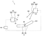
- the head side portion 331 of the backrest 33 of the front seat 3 moves in the longitudinal direction of the vehicle
- the head side portion 331 of the backrest 33 is located at the rear end That is, it shows a reclining state in which the angle of the backrest 33 approaches a flat state.
- the control device 40 increases the air conditioning capacity by the air conditioning air blown out from the second air outlet 210 as the portion 331 on the head side of the backrest 33 approaches the second air outlet 210 in the vehicle longitudinal direction, and the first blowing The air conditioning capacity by the air conditioning wind blown out from the outlet 110 is reduced.
- control device 40 increases the air volume B2 blown out from the second air outlet 210 as the region 331 on the head side of the backrest 33 approaches the second air outlet 210 in the vehicle longitudinal direction, The air volume A2 blown out from the first air outlet 110 is reduced.
- the control device 40 automatically adjusts the vertical angle of the air-conditioning air blown from the second air outlet 210 according to the angle or the position of the backrest 33.
- the magnitude relationship of the air volumes blown out from the first outlet 110 and the second outlet 210 is A1> A2 ⁇ 0, B2> B1 ⁇ 0.
- the air volumes A1, A2, B1 and B2 blown out from the first air outlet 110 and the second air outlet 210 respectively fall on the backrest 33 regardless of the angle of the backrest 33 of the front seat 3
- the total air conditioning capacity supplied to the seated occupant is set to be substantially the same.
- the air conditioning system 1 can reduce the load on each air conditioner and can enhance the comfort of the occupant.
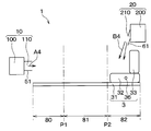
- FIGS. 10 and 11 A third embodiment will be described with reference to FIGS. 10 and 11.
- the third embodiment is the same as the first embodiment except that the configurations of the first air conditioner 10 and the second air conditioner 20 are modified with respect to the first embodiment, and the other features are the same as the first embodiment. Only the differences will be explained.
- the first air conditioning unit 100 of the first air conditioner 10 includes a face outlet 114, a foot outlet (not shown), a defroster outlet (not shown), and the like.
- An application blowout opening 117 is provided.
- a first other-use duct 54 is connected to the first other-use blowout opening 117.
- the outlet of the first other use duct 54 corresponds to the first other use outlet 540.
- the first air conditioning unit 100 and the ducts 51 and 54 may be integrated.
- the second air conditioning unit 200 of the second air conditioner 20 is provided with a second multipurpose blowout opening 216.
- a second other use duct 63 is connected to the second other use blowout opening 216.
- the outlet of the second other use duct 63 corresponds to the second other use outlet 630.
- the second air conditioning unit 200 and the ducts 61 and 63 may be integrated.
- the conditioned air blown out from the first other-purpose air outlet 540 and the second other-purpose air outlet 630 is used for applications other than the cabin air conditioning.
- the conditioned air is supplied to a battery pack 70 mounted on a vehicle, and used for temperature control of a battery (not shown) stored in the battery pack 70.
- the conditioned air blown out from the first other application outlet 540 and the second other application outlet 630 is not limited to the temperature control of the battery, and the temperature control of the temperature refrigerator mounted on the vehicle or the air in the passenger compartment It can be used for various applications such as exhaustion (ie ventilation in a car).
- the first air conditioner 10 has a first air volume adjustment unit 120 that adjusts the air volume blown out from the first outlet 110 and the air volume blown out from the first other application outlet 540.
- the first air volume adjustment unit 120 is configured of, for example, a face door 17 that opens and closes the face outlet opening 114 and a first other application door 121 that opens and closes the first other application outlet opening 117.
- the first air volume adjustment unit 120 is a rotary door or a slide door configured to close the other opening as the opening of one of the face outlet 114 and the first other application outlet 117 is opened. May be integrated.
- the second air conditioner 20 also has a second air volume adjustment unit 220 that adjusts the air volume blown out from the second air outlet 210 and the air volume blown out from the second other application air outlet 630.
- the second air volume adjustment unit 220 includes, for example, a ceiling blowout door as the second mode switching door 27 for opening and closing the ceiling blowout opening 214 and a second other use door 221 for opening and closing the second other use blowout opening 216. It is done.
- the second air volume adjustment unit 220 is also configured as a rotary door or a slide door configured to close the other of the ceiling blowout opening 214 and the second other-use blowout opening 216 as the opening is opened. May be integrated.
- the control device 40 of the third embodiment also controls the drive of the first air conditioner 10 and the second air conditioner 20 according to the position of the seat 32 as the movable portion of the front seat 3 detected by the position detection unit 30. .
- FIG. 10 shows a state in which the seat portion 32 is positioned at the forefront in a range in which the seat portion 32 of the front seat 3 moves in the longitudinal direction of the vehicle.
- the control device 40 increases the air amount A1 blown out from the first air outlet 110 and reduces the air amount B1 blown out from the second air outlet 210. Do.
- the control device 40 reduces the air volume C1 blown out from the first other use outlet 540, and increases the air volume D1 blown out from the second other use outlet 630.
- the control device 40 drives and controls the first air volume adjustment unit 120 as the seat portion 32 of the front seat 3 approaches the first air outlet 110, so that the air volume blown out from the first air outlet 110 A1 is enlarged, and the air volume C1 blown out from the first other-purpose air outlet 540 is decreased.
- the control device 40 drives and controls the second air volume adjustment unit 220 to reduce the air volume B1 blown out from the second air outlet 210, and the air volume D1 blown out from the second other use air outlet 630. Enlarge.
- FIG. 11 shows a state in which the seat portion 32 is located at the rearmost position in the range in which the seat portion 32 of the front seat 3 moves in the vehicle longitudinal direction.
- the control device 40 reduces the air amount A2 blown out from the first air outlet 110 and increases the air amount B2 blown out from the second air outlet 210. Do.
- the control device 40 increases the air volume C2 blown out from the first other application outlet 540, and from the second other application outlet 630 Reduce the air volume D2 to be blown out.
- the control device 40 drives and controls the first air volume adjustment unit 120 as the seat portion 32 of the front seat 3 approaches the second air outlet 210 so that the air volume blown out from the first air outlet 110 A2 is made smaller, and the air volume C2 blown out from the first other use outlet 540 is made larger.
- the control device 40 drives and controls the second air volume adjustment unit 220 to increase the air volume B2 blown out from the second air outlet 210, and the air volume D2 blown out from the second other use air outlet 630. Make it smaller.
- the first air conditioner 10 and the second air conditioner 20 can be used for various uses other than the cabin air conditioning. Then, among the first air conditioner 10 and the second air conditioner 20, the conditioned air blown out from the other-purpose air outlets 540, 630 of the air conditioner having a smaller load for air conditioning in the vehicle cabin is mainly in the vehicle cabin. Used for applications other than air conditioning. Therefore, it is possible to prevent the load from being concentrated on one of the fans 13 and 23 of either the first air conditioner 10 or the second air conditioner 20. Therefore, this air conditioning system can reduce the load of the fans 13 and 23 which the first air conditioner 10 and the second air conditioner 20 respectively have, and can extend the life.
- control device 40 controls the drive of the first air volume adjustment unit 120 so that the air volume blown out from the first outlet 110 and the air volume blown out from the first other application outlet 540 It is possible to adjust In addition, the control device 40 can adjust the amount of air blown out from the second air outlet 210 and the amount of air blown out from the second non-use air outlet 630 by controlling the drive of the second air volume adjustment unit 220. It is.
- FIGS. 12 to 14 The fourth embodiment is the same as the first embodiment except that the configurations of the outlets of the first air conditioner 10 and the second air conditioner 20 are modified with respect to the first embodiment. Only parts different from the one embodiment will be described.
- the outlet of the first foot duct 52 connected to the first foot outlet 115 provided in the first air conditioning unit 100 of the first air conditioner 10 corresponds to the first outlet 110.
- the first foot duct 52 can blow conditioned air toward the feet of the occupant seated in the front seat 3 from the first air outlet 110 provided below the instrument panel.
- the first air conditioner 10 may integrally configure the first air conditioning unit 100 and the first foot duct 52.
- the outlet of the second foot duct 62 connected to the second foot outlet 215 provided in the second air conditioning unit 200 of the second air conditioner 20 corresponds to the second outlet 210.
- the second foot duct 62 can blow conditioned air toward the feet of the occupant seated in the front seat 3 from the second air outlet 210 provided at the rear of the front seat 3.
- the 2nd air conditioner 20 may comprise the 2nd air conditioning unit 200 and the 2nd foot duct 62 in one.
- a space 35 through which wind can pass is provided between the seat portion 32 of the front seat 3 and the floor 7 of the vehicle body. Therefore, the conditioned air blown out from the second air outlet 210 passes through the space 35 between the seat portion 32 of the front seat 3 and the floor 7 of the vehicle body and is delivered to the feet of the occupant seated in the front seat 3.
- the control device 40 of the fourth embodiment also controls the driving of the first air conditioner 10 and the second air conditioner 20 according to the position of the seat 32 of the front seat 3 detected by the position detector 30.
- FIG. 12 shows a state where the seat portion 32 is positioned at the forefront in a range in which the seat portion 32 of the front seat 3 moves in the vehicle longitudinal direction.
- the control device 40 increases the air conditioning capacity by the conditioned air blown out from the first outlet 110 as the seat 32 of the front seat 3 gets closer to the first outlet 110, and the air conditioner blown out from the second outlet 210 Reduce the air conditioning capacity by wind.
- the control device 40 increases the air amount A1 blown out from the first outlet 110, and is blown out from the second outlet 210.
- the drive of the first blower 13 and the second blower 23 is controlled so as to reduce the air volume B1.
- FIG. 13 shows a state where the seat portion 32 is located at the rearmost position in the range in which the seat portion 32 of the front seat 3 moves in the vehicle longitudinal direction.
- the control device 40 increases the air conditioning capacity by the air conditioning air blown out from the second air outlet 210 as the seat portion 32 of the front seat 3 approaches the second air outlet 210, and the air conditioning blown out from the first air outlet 110 Reduce the air conditioning capacity by wind.
- the control device 40 increases the air amount B2 blown out from the second outlet 210 and is blown out from the first outlet 110.
- the drive of the first blower 13 and the second blower 23 is controlled so as to reduce the air volume A2.
- the magnitude relationship of the air volumes is A1> A2 ⁇ 0, B2> B1 ⁇ 0. Then, the air volumes A1, A2, B1 and B2 blown out from the first air outlet 110 and the second air outlet 210 respectively sit on the front seat 3 regardless of the position of the seat portion 32 of the front seat 3
- the total air conditioning capacity supplied to the occupants is set to be substantially the same.
- the air conditioning system 1 of the fourth embodiment described above can also achieve the same effects as the first embodiment and the like in the lower body air conditioning.
- the fifth embodiment will be described with reference to FIGS.
- a part of the control method of the first air conditioner 10 and the second air conditioner 20 is modified with respect to the first embodiment, and the others are similar to the first embodiment. Only the differences from the first embodiment will be described.
- the position detection unit 30, the control device 40, and the like are not shown.
- the outlet of the face duct 51 corresponds to the first outlet 110.
- the outlet of the ceiling duct 61 corresponds to the second outlet 210.
- the control device 40 of the fifth embodiment also controls the driving of the first air conditioner 10 and the second air conditioner 20 according to the position of the seat 32 as the movable portion of the front seat 3 detected by the position detection unit 30. .
- the distance between the first outlet 110 and the second outlet 210 is assumed to be relatively large. In this case, when the seat portion 32 of the front seat 3 is in the vicinity of the foremost part, the air blowing from the second air outlet 210 may hardly affect the air conditioning feeling of the occupant sitting on the front seat 3. In addition, when the seat portion 32 of the front seat 3 is near the rear end, the air blowing from the first air outlet 110 may hardly affect the air conditioning feeling of the occupant sitting on the front seat 3. Therefore, the control device 40 divides the range in which the seat portion 32 moves in the vehicle longitudinal direction into the front area 80, the middle area 81, and the rear area 83, and performs different control in each area.
- the front area 80 refers to an area between the foremost portion and the first reference position P1.
- the intermediate area 81 refers to an area between the first reference position P1 and the second reference position P2.
- the rear area 83 refers to an area between the second reference position P2 and the rearmost portion.
- the first reference position P1 and the second reference position P2 can be arbitrarily set by experiment or the like. For example, when the seat portion 32 of the front seat 3 is in front of that position, the first reference position P1 hardly affects the feeling of air conditioning of the occupant seated in the front seat 3 by the air flow from the second outlet 210 It is set as a position. Also, for example, when the seat portion 32 of the front seat 3 is behind the position of the second reference position P2, the air flow from the first outlet 110 almost affects the air conditioning feeling of the occupant sitting on the front seat 3. It is set as a position to stop giving.
- the air volume blown out from the first air outlet 110 is A1
- the air volume blown out from the second air outlet 210 is Assume B1.
- the air volume blown out from the first outlet 110 is A2
- the second outlet 210 Let B2 be the amount of air blown out.
- the air volume blown out from the first outlet 110 is A3.
- B3 be the amount of air blown out.
- the air volume blown out from the first air outlet 110 is A4, and the air volume blown out from the second air outlet 210 is B4.
- the magnitude relationship between the air volumes blown out from the first air outlet 110 and the second air outlet 210 is A4 ⁇ A1 ⁇ A2> A3> A4 and B4 ⁇ B1 ⁇ B2> B3> B4.
- control of the control device 40 when the center 36 of the seat portion 32 of the front seat 3 is in the front area 80 will be described with reference to FIGS. 15 and 16.
- the control device 40 increases the air volumes A1 and A2 blown out from the first air outlet 110 as the seat portion 32 is farther from the first air outlet 110.
- the air volume of the second air outlet 210 is gradually increased from the minimum B1 and B2.
- the control device 40 reduces the air volumes A2 and A1 blown out from the first outlet 110.
- the air volumes B2 and B1 of the second air outlet 210 are also gradually reduced.
- Control of the control device 40 when the center 36 of the seat portion 32 of the front seat 3 is in the middle area 81 will be described with reference to FIGS. 16 and 17.
- the control device 40 reduces the air volumes A2 and A3 blown out from the first air outlet 110 and blows it out from the second air outlet 210.
- Air volume B2 and B3 are increased.
- the control device 40 increases the air volumes A3 and A2 blown out from the first outlet 110 as the seat 32 of the front seat 3 approaches the first outlet 110, and then blown out from the second outlet 210 Reduce the air volume B3 and B2. That is, in the fifth embodiment, when the center 36 of the seat portion 32 of the front seat 3 is in the middle area 81, the same control as that in the first embodiment and the like is performed.
- control device 40 increases the air volumes B4 and B3 blown out from the second air outlet 210 as the seat portion 32 is farther from the second air outlet 210. At this time, the air volumes A4 and A3 of the first air outlet 110 are gradually increased from the minimum. In other words, as the seat portion 32 approaches the second air outlet 210, the control device 40 reduces the air volumes B3 and B4 blown out from the second air outlet 210. At this time, the air volumes A3 and A4 of the first air outlet 110 are also gradually reduced.
- the load of the air conditioners 10 and 20 is controlled by performing the same control as in the first embodiment. While reducing, it can improve the comfort of the occupant.
- the conditioned air blown out from the first air outlet 110 can be mainly used to enhance the comfort of the occupant.
- the conditioned air blown out from the second air outlet 210 can be mainly used to enhance the comfort of the occupant.
- control device adjusts the air volume blown out from the first and second outlets according to the position or the angle of the movable portion of the front seat, but the invention is not limited thereto.
- control device may adjust the temperature and humidity of the conditioned air blown out from the first and second outlets according to the position or angle of the movable part of the front seat.
- the air volume adjustment unit for adjusting the air volume blown out from each air outlet is provided in each air conditioning unit, but the present invention is not limited thereto.
- the air flow rate adjustment unit may be provided in a duct connected to each air conditioning unit.
- the air conditioning system has been described as being mounted on a two-row vehicle equipped with a front seat and a rear seat, but the invention is not limited thereto. In other embodiments, the air conditioning system may be mounted on a single row seat vehicle or a triple row seat vehicle.
- an air conditioning system mounted on a vehicle including a front seat having at least a movable portion movable in the longitudinal direction of the vehicle is: A first air conditioner, a second air conditioner, a position detector, and a controller are provided.
- the first air conditioner has a first blower for blowing the conditioned air, and a first outlet for blowing the conditioned air blown by the first blower from the front of the vehicle to the occupant seated in the front seat.
- the second air conditioner has a second blower for blowing the conditioned air, and a second outlet for blowing the conditioned air blown by the second blower from the rear of the vehicle to the occupant seated in the front seat.
- the position detection unit detects the position or angle of the movable portion of the front seat.
- the control device controls the driving of the first air conditioner and the second air conditioner in accordance with the position or the angle of the movable portion detected by the position detection unit.
- the control device increases the air conditioning capability by the air conditioning wind blown out from the first outlet as the movable portion approaches the first outlet in the whole area or a part of the range in which the movable portion moves in the vehicle longitudinal direction. And reduce the air conditioning capacity by the air conditioning air blown out from the second air outlet.
- the control device increases the air conditioning capacity by the air conditioning air blown out from the second air outlet as the movable part approaches the second air outlet, and reduces the air conditioning capacity by the air conditioning air blown out from the first air outlet. .
- control device increases the air volume blown out from the first air outlet as the movable part approaches the first air outlet, and reduces the air volume blown out from the second air outlet. Further, the control device increases the amount of air blown out from the second outlet as the movable part approaches the second outlet, and reduces the amount of air blown out from the first outlet.
- the load of each fan can be reduced by distributing the load to both fans without concentrating the load on any one of the first fan and the second fan.
- the amount of air blown out from the blowout port closer to the movable portion of the front seat among the first blowout port and the second blowout port is increased, the occupant is given a strong feeling of wind speed with punching power. Can.
- the conditioned air blown out from the first and second air outlets collide with each other and stay in the vicinity of the occupant, it becomes possible to efficiently perform air conditioning in the vicinity of the occupant. Therefore, this air conditioning system can reduce the load on the blowers of the individual air conditioners and can enhance the comfort of the occupant.
- the control device increases the air volume blown out from the first air outlet as the movable part approaches the first air outlet, and reduces the air volume blown out from the second air outlet.
- the driving of the first fan and the second fan is controlled.
- the control device increases the amount of air blown out from the second outlet as the movable part approaches the second outlet, and reduces the amount of air blown out from the first outlet and the first blower and the second fan. Control the drive of the blower. According to this, the load of each fan can be reduced by distributing the load to both fans without concentrating the load on any one of the first fan and the second fan.
- the first air conditioner further includes a first other-purpose air outlet that is used for applications other than in-vehicle air conditioning.
- the second air conditioner further includes a second other-purpose air outlet used for applications other than in-vehicle air conditioning.
- the control device increases the air volume blown out from the first air outlet as the movable part approaches the first air outlet, and reduces the air volume blown out from the first other application air outlet, and from the second air outlet Reduce the amount of air blown out and increase the amount of air blown out from the second all-purpose air outlet.
- control device reduces the amount of air blown out from the first outlet as the movable part approaches the second outlet, and increases the amount of air blown out from the first other application outlet, and the second blow The amount of air blown out from the outlet is increased, and the amount of air blown out from the second other use outlet is reduced.
- the conditioned air blown out from the other-purpose air outlet of the air conditioner having a smaller load for air conditioning the vehicle interior is used for applications other than air conditioning in the vehicle interior Mainly used. Therefore, it is possible to prevent the load from being concentrated on one fan of the first air conditioner and the second air conditioner, and it is possible to reduce the load of the fan that each air conditioner has.
- the first air conditioner further includes a first air volume adjustment unit that adjusts the air volume blown out from the first outlet and the air volume blown out from the first other application outlet.
- the second air conditioner further includes a second air volume adjustment unit that adjusts the air volume blown out from the second air outlet and the air volume blown out from the second other use air outlet.
- the control device increases the amount of air blown out from the first outlet as the movable part approaches the first outlet, and reduces the amount of air blown out from the outlet for the other first use.
- Drive control controls the drive of the second air volume adjustment unit so as to reduce the air volume blown out from the second air outlet and increase the air volume blown out from the second other application air outlet.
- control device reduces the amount of air blown out from the first outlet as the movable part approaches the second outlet, and adjusts the amount of first air so as to increase the amount of air blown out from the first other application outlet.
- Drive control of the unit At that time, the control device controls the drive of the second air volume adjustment unit so as to increase the air volume blown out from the second air outlet and to decrease the air volume blown out from the second other use air outlet.
- control device can adjust the air volume blown out from the first outlet and the air volume blown out from the first other application outlet by controlling the drive of the first air volume adjustment unit. is there.
- control device can adjust the amount of air blown out from the second outlet and the amount of air blown out from the second other-purpose outlet by controlling the drive of the second air amount adjusting unit.
- the conditioned air blown out from the first other use outlet and the second other use outlet is temperature control of the battery mounted on the vehicle, temperature control of the heating refrigerator, or air in the passenger compartment. Used for any of the discharges of According to this, it is possible to use the 1st air conditioner and the 2nd air conditioner for various uses other than car interior air conditioning.
- a range in which the movable portion moves in the vehicle longitudinal direction is a front region between the foremost portion and a predetermined first reference position, and a second reference position and a rear portion behind the first reference position. , And an intermediate region between the first reference position and the second reference position.
- the control device performs control of at least one of the above-described first to fifth aspects when the movable portion is in the intermediate region. Then, when the movable portion is in the front area, the control device increases the amount of air blown from the first air outlet as the movable portion is farther from the first air outlet. In addition, when the movable part is in the rear region, the amount of air blown out from the second air outlet is increased as the movable part is farther from the second air outlet.
- the air conditioning of the passenger whose air is blown from the second outlet is seated on the front seat
- it has little effect on the feeling.
- the air blowing from the first air outlet may hardly affect the air conditioning feeling of the occupant seated in the front seat. Therefore, when the movable portion of the front seat is in the front area, the conditioned air blown out from the first air outlet can be mainly used to enhance the comfort of the occupant.
- the conditioned air blown out from the second air outlet can be mainly used to enhance the comfort of the occupant.
- the control of at least one of the first to fifth aspects described above is performed to reduce the load on the air conditioner and to reduce the occupant's load. You can enhance the sense of comfort.
Abstract
A first air conditioning device (10) has a first outlet (110) for jetting conditioned air from the vehicle front toward an occupant (6) seated in a front seat (3). A second air conditioning device (20) has a second outlet (210) for jetting conditioned air from the vehicle rear toward the occupant (6) seated in the front seat (3). The more closely the moving parts (32, 33) of the front seat (3) approach the first outlet (110) within all or a part of the range of motion of the moving parts (32, 33) in vehicle front-rear direction, the more a control device (40) increases the air conditioning power based on conditioned air jetted from the first outlet (110) and decreases the air conditioning power based on conditioned air jetted from the second outlet (210). The control device (40) also increases the air conditioning power based on conditioned air jetted from the second outlet (210) and decreases the air conditioning power based on conditioned air jetted from the first outlet (110) the more closely the moving parts (32, 33) approach the second outlet (210).
Description
本出願は、2017年11月17日に出願された日本特許出願番号2017-222195号に基づくもので、ここにその記載内容が参照により組み入れられる。
This application is based on Japanese Patent Application No. 2017-222195 filed on Nov. 17, 2017, the contents of which are incorporated herein by reference.
本開示は、車両用の空調システムに関するものである。
The present disclosure relates to an air conditioning system for a vehicle.
従来、車室内の空調を行う空調システムが知られている。特許文献1に記載の空調システムは、インストルメントパネルに設けられた吹出口から吹き出される空調風の風量を、車両前後方向に移動する前座席の位置に応じて調整するものである。具体的には、この空調システムは、前座席の位置が吹出口に近づくほど、吹出口から吹き出される風量を小さくし、前座席の位置が吹出口から遠くなるほど、吹出口から吹き出される風量を大きくする。これにより、この空調システムは、前座席に着座する乗員に対し一定の空調感を与えている。
BACKGROUND Conventionally, an air conditioning system for air conditioning a vehicle interior is known. The air conditioning system described in Patent Document 1 adjusts the air volume of conditioned air blown out from an outlet provided in an instrument panel according to the position of a front seat moving in the longitudinal direction of the vehicle. Specifically, the air conditioning system reduces the amount of air blown out from the outlet as the position of the front seat approaches the outlet, and the amount of air blown out from the outlet as the position of the front seat moves farther from the outlet. Increase the Thus, the air conditioning system provides a certain degree of air conditioning to the occupant seated in the front seat.
しかしながら、特許文献1に記載の空調システムは、前座席の位置が吹出口から遠くなると大風量が要求されるため、空調装置が備える送風機および冷凍サイクルを構成する圧縮機などの負荷が大きくなる。そのため、空調装置の寿命が短くなるおそれがある。
また、この空調システムは、前座席の位置が吹出口から遠くなると、吹出口から吹き出された空調風が乗員に到達するまでに拡散してしまう。そのため、乗員に対してパンチ力のある強い空調感を与えることができないため、乗員が物足りなさを感じることが懸念される。 However, the air conditioning system described inPatent Document 1 requires a large amount of air when the position of the front seat is far from the air outlet, so the load of the blower and the compressor that constitutes the refrigeration cycle of the air conditioner becomes large. Therefore, the life of the air conditioner may be shortened.
Further, in the air conditioning system, when the position of the front seat is far from the air outlet, the air conditioned air blown out from the air outlet diffuses before reaching the occupant. As a result, since the occupant can not be given a strong feeling of air conditioning having a punching power, there is a concern that the occupant may feel a lack of objectivity.
また、この空調システムは、前座席の位置が吹出口から遠くなると、吹出口から吹き出された空調風が乗員に到達するまでに拡散してしまう。そのため、乗員に対してパンチ力のある強い空調感を与えることができないため、乗員が物足りなさを感じることが懸念される。 However, the air conditioning system described in
Further, in the air conditioning system, when the position of the front seat is far from the air outlet, the air conditioned air blown out from the air outlet diffuses before reaching the occupant. As a result, since the occupant can not be given a strong feeling of air conditioning having a punching power, there is a concern that the occupant may feel a lack of objectivity.
本開示は、空調装置の負荷を軽減すると共に、乗員の快適感を高めることの可能な空調システムを提供することを目的とする。
The present disclosure aims to provide an air conditioning system capable of reducing the load on the air conditioner and enhancing the comfort of the occupant.
本開示の1つの観点によれば、車両前後方向に移動可能な可動部を少なくとも一部に有する前座席を備えた車両に搭載される空調システムであって、
空調風を送風する第1送風機、および、その第1送風機により送風される空調風を前座席に着座する乗員に対し車両前方から吹き出す第1吹出口を有する第1空調装置と、
空調風を送風する第2送風機、および、その第2送風機により送風される空調風を前座席に着座する乗員に対し車両後方から吹き出す第2吹出口を有する第2空調装置と、
前座席が有する可動部の位置または角度を検出する位置検出部と、
位置検出部により検出される可動部の位置または角度に応じて第1空調装置と第2空調装置の駆動を制御する制御装置と、を備え、
制御装置は、
可動部が車両前後方向に移動する範囲の全域もしくは一部において、
可動部が第1吹出口に近づくほど、第1吹出口から吹き出される空調風による空調能力を大きくし、第2吹出口から吹き出される空調風による空調能力を小さくし、
可動部が第2吹出口に近づくほど、第2吹出口から吹き出される空調風による空調能力を大きくし、第1吹出口から吹き出される空調風による空調能力を小さくする。 According to one aspect of the present disclosure, there is provided an air conditioning system mounted on a vehicle including a front seat having at least a portion of a movable portion movable in the longitudinal direction of the vehicle,
A first air blower having a first air blower for blowing air conditioning air, and a first air outlet having a first air outlet blowing out air conditioning air blown by the first air blower from a front of the vehicle to an occupant seated in a front seat;
A second air blower having a second blower for blowing the air conditioning air, and a second air outlet for blowing the air conditioning air blown by the second blower from the rear of the vehicle to an occupant seated in the front seat;
A position detection unit that detects the position or angle of the movable unit of the front seat;
A control device that controls driving of the first air conditioner and the second air conditioner according to the position or angle of the movable part detected by the position detection unit;
The controller is
In all or part of the range in which the movable part moves in the longitudinal direction of the vehicle,
As the movable part approaches the first air outlet, the air conditioning capacity by the air conditioning air blown out from the first air outlet is increased, and the air conditioning capacity by the air conditioning air blown out from the second air outlet is decreased,
As the movable portion approaches the second air outlet, the air conditioning capacity by the air conditioning air blown out from the second air outlet is increased, and the air conditioning capacity by the air conditioning air blown out from the first air outlet is reduced.
これによれば、第1吹出口から吹き出される空調風と、第2吹出口から吹き出される空調風により、前座席に着座する乗員に対する空調を行うことが可能となる。そのため、第1空調装置と第2空調装置の両方に負荷を分散させることで、個々の空調装置の負荷を軽減し、空調装置の寿命を延ばすことができる。
According to this, it becomes possible to perform air conditioning for the occupant seated in the front seat by the conditioned air blown out from the first outlet and the conditioned air blown out from the second outlet. Therefore, by distributing the load to both the first air conditioner and the second air conditioner, the load of each air conditioner can be reduced and the life of the air conditioner can be extended.
また、第1吹出口と第2吹出口のうち、前座席の可動部に近い方の吹出口から吹き出される空調風による空調能力を大きくするので、乗員に対し、いわゆるパンチ力のある強い空調感を与えることができる。
In addition, since the air conditioning capacity by the air conditioning wind blown out from the blowout port closer to the movable portion of the front seat among the first blowout port and the second blowout port is increased, the air conditioning having a so-called punch power is strong Can give a feeling.
さらに、第1吹出口と第2吹出口のそれぞれから吹き出される空調風が乗員付近でぶつかり合い、乗員近傍に空調風が滞留する効果が得られる。そのため、第1吹出口と第2吹出口のいずれか一方から送風する場合に比べて、空調風の拡散が抑制されるので、乗員近傍を効率よく空調することが可能になる。したがって、この空調システムは、個々の空調装置の負荷を軽減すると共に、乗員の快適感を高めることができる。
Furthermore, the conditioned air blown out from each of the first and second outlets collides with each other in the vicinity of the occupant, so that the conditioned air can be retained in the vicinity of the occupant. Therefore, compared with the case where the air is blown from any one of the first and second air outlets, the diffusion of the conditioned air is suppressed, so that the area near the occupant can be efficiently air-conditioned. Therefore, this air conditioning system can reduce the load on the individual air conditioners and enhance the comfort of the occupant.
なお、上記各構成に付した括弧内の符号は、後述する実施形態に記載する具体的構成との対応関係の一例を示したものである。
In addition, the code | symbol in the parenthesis attached | subjected to each said structure shows an example of the correspondence with the specific structure described in embodiment mentioned later.
以下、本開示の実施形態について図面を参照しつつ説明する。なお、以下の各実施形態相互において、互いに同一もしくは均等である部分には、同一符号を付し、その説明を省略する。
Hereinafter, embodiments of the present disclosure will be described with reference to the drawings. In the following embodiments, parts identical or equivalent to each other are given the same reference numerals, and descriptions thereof will be omitted.
(第1実施形態)
第1実施形態について図面を参照しつつ説明する。本実施形態の空調システム1は、車両2に搭載され、所定の空調モードに応じて温度および湿度を調整した空調風を複数の吹出口から車室内に吹き出すことで、車室内の空気調和を行うものである。 First Embodiment
A first embodiment will be described with reference to the drawings. Theair conditioning system 1 of the present embodiment is mounted on the vehicle 2 and blows out conditioned air whose temperature and humidity are adjusted according to a predetermined air conditioning mode from a plurality of outlets into the vehicle compartment, thereby performing air conditioning of the vehicle interior. It is a thing.
第1実施形態について図面を参照しつつ説明する。本実施形態の空調システム1は、車両2に搭載され、所定の空調モードに応じて温度および湿度を調整した空調風を複数の吹出口から車室内に吹き出すことで、車室内の空気調和を行うものである。 First Embodiment
A first embodiment will be described with reference to the drawings. The
図1に示すように、この車両2は、前座席3と後座席4を備えている。前座席3は、車両前後方向に延びるレール31と、そのレール31の上を移動可能な座部32および背凭れ33を有している。第1実施形態では、前座席3の座部32が、車両前後方向に移動可能な可動部に相当する。
As shown in FIG. 1, the vehicle 2 includes a front seat 3 and a rear seat 4. The front seat 3 has a rail 31 extending in the front-rear direction of the vehicle, and a seat 32 and a backrest 33 movable on the rail 31. In the first embodiment, the seat portion 32 of the front seat 3 corresponds to a movable portion movable in the longitudinal direction of the vehicle.
空調システム1は、第1空調装置10、第2空調装置20、位置検出部30および制御装置40などを備えている。第1空調装置10は、インストルメントパネル5の内側に設けられている。第1空調装置10は、空調風を生成する第1空調ユニット100と、その第1空調ユニット100で生成された空調風を、前座席3に着座する乗員6に対し車両前方から吹き出す第1吹出口110を有している。
The air conditioning system 1 includes a first air conditioner 10, a second air conditioner 20, a position detection unit 30, a control device 40, and the like. The first air conditioner 10 is provided inside the instrument panel 5. The first air conditioner 10 generates a first air conditioning unit 100 that generates conditioned air and a first blow that blows out the conditioned air generated by the first air conditioning unit 100 from the front of the vehicle to the occupant 6 seated on the front seat 3. It has an outlet 110.
図4は、第1空調装置10の模式図である。図4に示すように、第1空調装置10は、第1空調ユニット100と、複数のダクト51、52、53を備えている。第1実施形態では、複数のダクトのうち、フェイスダクト51の吹出口が、上述の第1吹出口110に相当する。フェイスダクト51は、インストルメントパネル5に設けられた第1吹出口110から前座席3に着座する乗員6の上半身またはその周囲に向けて空調風を吹き出すことが可能である。なお、第1空調装置10は、第1空調ユニット100と複数のダクト51、52、53とを一体に構成してもよい。または、第1空調装置10の吹出開口部114、115、116から空調風が直接吹き出される構成としてもよい。
FIG. 4 is a schematic view of the first air conditioner 10. As shown in FIG. 4, the first air conditioner 10 includes a first air conditioning unit 100 and a plurality of ducts 51, 52, 53. In the first embodiment, among the plurality of ducts, the outlet of the face duct 51 corresponds to the first outlet 110 described above. The face duct 51 can blow conditioned air toward the upper body or the periphery of the occupant 6 seated on the front seat 3 from the first outlet 110 provided in the instrument panel 5. The first air conditioner 10 may integrally configure the first air conditioning unit 100 and the plurality of ducts 51, 52, 53. Alternatively, the conditioned air may be directly blown out from the blowout openings 114, 115, 116 of the first air conditioner 10.
第1空調ユニット100の構成について説明する。第1空調ユニット100は、空調ケース11の内側に、内外気切替ドア12、送風機13、エバポレータ14、ヒータコア15、エアミックスドア16およびモード切替ドア17、18、19などを備えている。空調ケース11に内側には、空気が流れる通風路111が形成されている。また、空調ケース11は、通風路111の空気流れ方向上流側に、車室内の所定箇所から通風路111に内気を導入するための内気導入口112と、車外から通風路111に外気を導入するための外気導入口113を有している。
The configuration of the first air conditioning unit 100 will be described. The first air conditioning unit 100 includes an inside / outside air switching door 12, a blower 13, an evaporator 14, a heater core 15, an air mixing door 16, mode switching doors 17, 18, 19 and the like inside the air conditioning case 11. Inside the air conditioning case 11, a ventilation path 111 through which air flows is formed. Further, the air conditioning case 11 introduces outside air into the air flow passage 111 from the outside of the vehicle and the inside air introduction port 112 for introducing the air into the air flow passage 111 from a predetermined location in the vehicle room on the air flow direction upstream side of the air flow passage 111 It has an outside air introduction port 113 for.
内外気切替ドア12は、内気導入口112の開口面積と、外気導入口113の開口面積を連続的に調整するものである。内外気切替ドア12は、内気導入口112と外気導入口113のうち、一方の開口部を開くほど他方の開口部を閉じるように回転動作する。これにより、内外気切替ドア12は、通風路111に導入される内気の風量と外気の風量の割合を調整することが可能である。
The inside / outside air switching door 12 continuously adjusts the opening area of the inside air introduction port 112 and the opening area of the outside air introduction port 113. The inside / outside air switching door 12 rotates so as to close the other opening as the opening of one of the inside air introduction port 112 and the outside air introduction port 113 is opened. Thus, the inside / outside air switching door 12 can adjust the ratio of the air volume of the inside air introduced into the ventilation path 111 and the air volume of the outside air.
送風機13は、遠心ファン131と、その遠心ファン131を回転駆動するモータ132などから構成されている。モータ132の駆動と共に遠心ファン131が回転すると、通風路111に空気が送風される。これにより、内気導入口112または外気導入口113から通風路111に内気または外気が導入される。送風機13により送風されて通風路111を流れる空気は、エバポレータ14およびヒータコア15により温度および湿度が調整され、通風路111に連通する複数の吹出開口部114、115、116のいずれかを経由して車室内に吹き出される。
The blower 13 is composed of a centrifugal fan 131, a motor 132 for rotationally driving the centrifugal fan 131, and the like. When the centrifugal fan 131 rotates with the drive of the motor 132, air is blown to the air passage 111. As a result, inside air or outside air is introduced into the ventilation path 111 from the inside air introduction port 112 or the outside air introduction port 113. The temperature and humidity of the air blown by the blower 13 and flowing through the ventilation path 111 are adjusted by the evaporator 14 and the heater core 15, and any of the plurality of blowout openings 114, 115, 116 communicating with the ventilation path 111 It is blown out into the passenger compartment.
エバポレータ14は、通風路111を流れる空気を冷却するための熱交換器である。エバポレータ14は、図示していない圧縮機、凝縮器および膨張弁などと共に周知の冷凍サイクルを構成している。エバポレータ14が有する図示していないチューブの中を、気液二層状態となった冷媒が流れる。エバポレータ14は、そのチューブの内側を流れる冷媒の蒸発潜熱により、通風路111を流れる空気を冷却する。
The evaporator 14 is a heat exchanger for cooling the air flowing through the air passage 111. The evaporator 14 constitutes a known refrigeration cycle together with a compressor, a condenser, an expansion valve and the like which are not shown. The refrigerant in a gas-liquid two-layer state flows through a tube (not shown) of the evaporator 14. The evaporator 14 cools the air flowing through the air passage 111 by the latent heat of evaporation of the refrigerant flowing inside the tube.
ヒータコア15は、通風路111を流れる空気を加熱するための熱交換器である。ヒータコア15が有する図示していないチューブの内側を温水等が流れる。ヒータコア15は、そのチューブの内側を流れる温水等と、通風路111を流れる空気との熱交換により、通風路111を流れる空気を加熱する。
The heater core 15 is a heat exchanger for heating the air flowing through the air passage 111. Hot water or the like flows inside the tube (not shown) of the heater core 15. The heater core 15 heats the air flowing through the air passage 111 by heat exchange between the warm water flowing inside the tube and the air flowing through the air passage 111.
エバポレータ14とヒータコア15との間には、エアミックスドア16が設けられている。エアミックスドア16は、エバポレータ14を通過した後にヒータコア15を迂回して流れる風量と、エバポレータ14を通過した後にヒータコア15を通過する風量との割合を調整する。
An air mix door 16 is provided between the evaporator 14 and the heater core 15. The air mix door 16 adjusts the ratio of the air volume flowing around the heater core 15 after passing through the evaporator 14 and the air volume passing through the heater core 15 after passing through the evaporator 14.
空調ケース11は、通風路111の空気流れ方向下流側に、通風路111から車室内に空気を送風するための複数の吹出開口部114、115、116を有している。複数の吹出開口部114、115、116は、例えば、フェイス吹出開口部114、フット吹出開口部115、デフロスタ吹出開口部116などにより構成されている。フェイス吹出開口部114は、前座席3に着座する乗員6の上半身またはその周囲に向けて空調風を吹き出すものである。フット吹出開口部115は、その乗員6の足元に向けて空調風を吹き出すものである。デフロスタ吹出開口部116は、車両2のフロントガラスに向けて空調風を吹き出すものである。
The air conditioning case 11 has, on the downstream side in the air flow direction of the air passage 111, a plurality of blowout openings 114, 115, 116 for blowing air from the air passage 111 into the vehicle compartment. The plurality of blowout openings 114, 115, 116 are configured by, for example, a face blowout opening 114, a foot blowout opening 115, a defroster blowout opening 116, and the like. The face blowout opening 114 blows the conditioned air toward the upper body of the occupant 6 seated in the front seat 3 or the periphery thereof. The foot blowout opening 115 blows the conditioned air toward the feet of the occupant 6. The defroster blowout opening 116 blows the conditioned air toward the windshield of the vehicle 2.
フェイス吹出開口部114、フット吹出開口部115およびデフロスタ吹出開口部116には、それぞれの開口部を開閉するためのモード切替ドア17、18、19が設けられている。モード切替ドア17、18、19は、フェイスドア17、フットドア18およびデフロスタドア19により構成されている。フェイスドア17は、フェイス吹出開口部114を開閉する。フットドア18は、フット吹出開口部115を開閉する。デフロスタドア19は、デフロスタ吹出開口部116を開閉する。なお、上述した内外気切替ドア12、エアミックスドア16、フェイスドア17、フットドア18およびデフロスタドア19はそれぞれ、図示していないサーボモータなどのアクチュエータによって駆動される。
The face blowing opening 114, the foot blowing opening 115, and the defroster blowing opening 116 are provided with mode switching doors 17, 18 and 19 for opening and closing the respective openings. The mode switching doors 17, 18, 19 are configured by the face door 17, the foot door 18 and the defroster door 19. The face door 17 opens and closes the face blowout opening 114. The foot door 18 opens and closes the foot outlet opening 115. The defroster door 19 opens and closes the defroster blowout opening 116. The inside / outside air switching door 12, the air mix door 16, the face door 17, the foot door 18, and the defroster door 19 described above are each driven by an actuator such as a servomotor (not shown).
第1空調ユニット100の空調ケース11が有する複数の吹出開口部114、115、116にはそれぞれ、空調ケース11とは別部材として構成された複数のダクト51、52、53が接続される。複数のダクト51、52、53は、例えば、フェイスダクト51、フットダクト52およびデフロスタダクト53等により構成される。フェイスダクト51は、フェイス吹出開口部114に接続される。フットダクト52は、フット吹出開口部115に接続される。デフロスタダクト53は、デフロスタ吹出開口部116に接続される。
A plurality of ducts 51, 52, 53 configured as separate members from the air conditioning case 11 are connected to the plurality of air outlet openings 114, 115, 116 of the air conditioning case 11 of the first air conditioning unit 100, respectively. The plurality of ducts 51, 52, 53 are constituted by, for example, the face duct 51, the foot duct 52, the defroster duct 53, and the like. The face duct 51 is connected to the face outlet 114. The foot duct 52 is connected to the foot outlet opening 115. The defroster duct 53 is connected to the defroster blowout opening 116.
次に、第2空調装置20について説明する。第2空調装置20は、空調風を生成する第2空調ユニット200と、その第2空調ユニット200で生成された空調風を前座席3に着座する乗員6に対し車両後方から吹き出す第2吹出口210を有している。なお、図1~図3では、第2空調ユニット200を車両天井に設置しているが、第2空調ユニット200を設置する位置はこれに限らない。第2空調ユニット200は、例えば、車両天井、後座席4の後方、または後座席4の側方など任意の場所に設置することが可能である。
Next, the second air conditioner 20 will be described. The second air conditioner 20 generates a second air conditioning unit 200 that generates conditioned air, and a second outlet that blows out the conditioned air generated by the second air conditioning unit 200 from the rear of the vehicle to the occupant 6 who sits on the front seat 3 It has 210. Although the second air conditioning unit 200 is installed on the vehicle ceiling in FIGS. 1 to 3, the position at which the second air conditioning unit 200 is installed is not limited to this. The second air conditioning unit 200 can be installed at any place, such as the vehicle ceiling, the rear of the rear seat 4, or the side of the rear seat 4, for example.
図5は、第2空調装置20の模式図である。図5に示すように、第2空調装置20は、第2空調ユニット200と、複数のダクト61、62を備えている。第2空調ユニット200も、第1空調ユニット100と同様に、空調ケース21の内側に、内外気切替ドア22、送風機23、エバポレータ24、ヒータコア25、エアミックスドア26およびモード切替ドア27、28などを備えている。送風機23は、遠心ファン231と、その遠心ファン231を回転駆動するモータ232などから構成されている。なお、第2空調ユニット200の空調ケース21が有する通風路211の下流側には、天井吹出開口部214とフット吹出開口部215が設けられており、デフロスタ吹出開口部は設けられていない。
FIG. 5 is a schematic view of the second air conditioner 20. As shown in FIG. As shown in FIG. 5, the second air conditioner 20 includes a second air conditioning unit 200 and a plurality of ducts 61 and 62. Similarly to the first air conditioning unit 100, the second air conditioning unit 200 also includes an inside / outside air switching door 22, a blower 23, an evaporator 24, a heater core 25, an air mix door 26, a mode switching door 27, 28 and the like inside the air conditioning case 21. Is equipped. The blower 23 is composed of a centrifugal fan 231, a motor 232 for rotationally driving the centrifugal fan 231, and the like. A ceiling outlet opening 214 and a foot outlet opening 215 are provided on the downstream side of the air passage 211 of the air conditioning case 21 of the second air conditioning unit 200, and no defroster outlet is provided.
第2空調ユニット200の空調ケース21に設けられた天井吹出開口部214には、天井ダクト61が接続されている。第2実施形態では、その天井ダクト61の吹出口が、上述の第2吹出口210に相当する。天井ダクト61は、車両天井に設けられた第2吹出口210から前座席3に着座する乗員6の上半身またはその周囲に向けて空調風を吹き出すことが可能である。なお、第2空調装置20も、第2空調ユニット200と複数のダクト61、62とを一体に構成してもよい。または、第2空調装置20の吹出開口部214、215から空調風が直接吹き出される構成としてもよい。
A ceiling duct 61 is connected to the ceiling blowout opening 214 provided in the air conditioning case 21 of the second air conditioning unit 200. In the second embodiment, the outlet of the ceiling duct 61 corresponds to the second outlet 210 described above. The ceiling duct 61 can blow conditioned air toward the upper body or the periphery of the occupant 6 seated on the front seat 3 from the second air outlet 210 provided in the vehicle ceiling. The second air conditioner 20 may also integrally configure the second air conditioning unit 200 and the plurality of ducts 61 and 62. Alternatively, the conditioned air may be directly blown out from the blowout openings 214 and 215 of the second air conditioner 20.
以下の説明では、第1空調ユニット100が備える各構成を、適宜、第1空調ケース11、第1内外気切替ドア12、第1送風機13、第1エバポレータ14、第1ヒータコア15、第1エアミックスドア16および第1モード切替ドア17、18、19と呼ぶことがある。また、第2空調ユニット200が備える各構成を、適宜、第2空調ケース21、第2内外気切替ドア22、第2送風機23、第2エバポレータ24、第2ヒータコア25、第2エアミックスドア26および第2モード切替ドア27、28と呼ぶことがある。
In the following description, the respective components included in the first air conditioning unit 100 are appropriately referred to as the first air conditioning case 11, the first inside / outside air switching door 12, the first blower 13, the first evaporator 14, the first heater core 15, the first air It may be called the mix door 16 and the first mode switching door 17, 18, 19. In addition, each configuration of the second air conditioning unit 200 may be appropriately determined by the second air conditioning case 21, the second inside / outside air switching door 22, the second blower 23, the second evaporator 24, the second heater core 25, the second air mix door 26. And the second mode switching door 27, 28.
図2および図3に示すように、第1実施形態の空調システム1は、前座席3の可動部としての座部32の位置に応じて、第1空調装置10と第2空調装置20の駆動が制御装置40により制御される構成である。前座席3の座部32の位置は、位置検出部30によって検出される。位置検出部30によって検出された前座席3の座部32の位置情報は、制御装置40に伝送される。
As shown in FIGS. 2 and 3, the air conditioning system 1 according to the first embodiment drives the first air conditioner 10 and the second air conditioner 20 according to the position of the seat 32 as the movable portion of the front seat 3. Are controlled by the control device 40. The position of the seat portion 32 of the front seat 3 is detected by the position detection unit 30. The position information of the seat portion 32 of the front seat 3 detected by the position detection unit 30 is transmitted to the control device 40.
制御装置40は、プロセッサ、メモリ等を有するコンピュータ、およびその周辺回路で構成されている。制御装置40のメモリは、非遷移的実体的記憶媒体で構成されている。なお、図1~図3では、第1空調装置10と第2空調装置20が1個の制御装置40により駆動制御されるように記載しているが、制御装置40の個数、配置等はこれに限らない。第1空調装置10と第2空調装置20を、別々の制御装置により駆動制御するように構成してもよい。
The control device 40 is configured by a computer having a processor, a memory, and the like, and peripheral circuits thereof. The memory of the control device 40 is configured of a non-transitional tangible storage medium. Although the first air conditioner 10 and the second air conditioner 20 are described as being driven and controlled by one control device 40 in FIGS. 1 to 3, the number and arrangement of the control devices 40 are the same. Not limited to. The first air conditioner 10 and the second air conditioner 20 may be drive-controlled by separate control devices.
制御装置40は、位置検出部30により検出される前座席3の座部32の位置に応じて第1空調装置10と第2空調装置20の駆動を制御する。第1実施形態では、制御装置40は、前座席3の座部32が車両前後方向に移動する範囲の全域もしくは一部において、第1空調装置10と第2空調装置20の駆動を制御する。
The control device 40 controls the driving of the first air conditioner 10 and the second air conditioner 20 according to the position of the seat portion 32 of the front seat 3 detected by the position detection unit 30. In the first embodiment, the control device 40 controls the driving of the first air conditioner 10 and the second air conditioner 20 in the whole area or a part of the range in which the seat portion 32 of the front seat 3 moves in the vehicle longitudinal direction.
図2は、前座席3の座部32が車両前後方向に移動する範囲の中で、その座部32が最前部に位置する状態を示している。制御装置40は、前座席3の座部32が第1吹出口110に近づくほど、第1吹出口110から吹き出される空調風による空調能力を大きくし、第2吹出口210から吹き出される空調風による第2空調装置20の空調能力を小さくする。具体的には、制御装置40は、前座席3の座部32が第1吹出口110に近づくほど、第1吹出口110から吹き出される風量を大きくし、第2吹出口210から吹き出される風量を小さくするよう、第1送風機13と第2送風機23の駆動を制御する。
FIG. 2 shows a state where the seat portion 32 is positioned at the forefront in a range in which the seat portion 32 of the front seat 3 moves in the longitudinal direction of the vehicle. The control device 40 increases the air conditioning capacity by the conditioned air blown out from the first outlet 110 as the seat 32 of the front seat 3 gets closer to the first outlet 110, and the air conditioner blown out from the second outlet 210 The air conditioning capacity of the second air conditioner 20 by wind is reduced. Specifically, the control device 40 increases the amount of air blown from the first air outlet 110 as the seat portion 32 of the front seat 3 approaches the first air outlet 110, and blows the air from the second air outlet 210. The drive of the first blower 13 and the second blower 23 is controlled so as to reduce the air volume.
一方、図3は、前座席3の座部32が車両前後方向に移動する範囲の中で、その座部32が最後部に位置する状態を示している。制御装置40は、前座席3の座部32が第2吹出口210に近づくほど、第2吹出口210から吹き出される空調風による空調能力を大きくし、第1吹出口110から吹き出される空調風による空調能力を小さくする。具体的には、制御装置40は、前座席3の座部32が第2吹出口210に近づくほど、第2吹出口210から吹き出される風量を大きくし、第1吹出口110から吹き出される風量を小さくするよう、第1送風機13と第2送風機23の駆動を制御する。なお、制御装置40は、前座席3の座部32の位置に応じて、第2吹出口210から吹き出される空調風の送風方向の上下角度を自動調節する。
On the other hand, FIG. 3 shows a state in which the seat portion 32 is located at the rearmost position in the range in which the seat portion 32 of the front seat 3 moves in the vehicle longitudinal direction. The control device 40 increases the air conditioning capacity by the air conditioning air blown out from the second air outlet 210 as the seat portion 32 of the front seat 3 approaches the second air outlet 210, and the air conditioning blown out from the first air outlet 110 Reduce the air conditioning capacity by wind. Specifically, the control device 40 increases the amount of air blown from the second air outlet 210 as the seat 32 of the front seat 3 approaches the second air outlet 210 and blows the air from the first air outlet 110 The drive of the first blower 13 and the second blower 23 is controlled so as to reduce the air volume. The control device 40 automatically adjusts the vertical angle of the air-conditioning air blown from the second air outlet 210 according to the position of the seat portion 32 of the front seat 3 in the blowing direction.
ここで、図2に示すように、前座席3の座部32が最前部に位置するとき、第1吹出口110から吹き出される風量をA1とし、第2吹出口210から吹き出される風量をB1とする。一方、図3に示すように、前座席3の座部32が最後部に位置するとき、第1吹出口110から吹き出される風量をA2とし、第2吹出口210から吹き出される風量をB2とする。このとき、各風量の大小関係は、A1>A2≧0、B2>B1≧0 である。そして、第1吹出口110と第2吹出口210からそれぞれ吹き出される風量A1、A2、B1、B2は、前座席3の座部32がどの位置にあっても、その前座席3に着座する乗員6に供給される合計空調能力がほぼ同一になるよう設定されている。なお、第1吹出口110と第2吹出口210からそれぞれ吹き出される風量の変化率は、正比例的なものに限らず、前座席3の各位置ごとに乗員6が最適な空調効果を得られるよう、実験等により適宜設定することが可能である。
Here, as shown in FIG. 2, when the seat portion 32 of the front seat 3 is located at the foremost position, the air volume blown out from the first air outlet 110 is A1 and the air volume blown out from the second air outlet 210 is Assume B1. On the other hand, as shown in FIG. 3, when the seat 32 of the front seat 3 is located at the rearmost position, the air volume blown out from the first outlet 110 is A2, and the air volume blown out from the second outlet 210 is B2. I assume. At this time, the magnitude relationship of the air volumes is A1> A2 ≧ 0, B2> B1 ≧ 0. Then, the air volumes A1, A2, B1 and B2 blown out from the first air outlet 110 and the second air outlet 210 respectively sit on the front seat 3 regardless of the position of the seat portion 32 of the front seat 3 The total air conditioning capacity supplied to the occupant 6 is set to be substantially the same. The rate of change of the air volume blown out from the first and second air outlets 110 and 210 is not limited to direct proportion, and the occupant 6 can obtain the optimum air conditioning effect at each position of the front seat 3 It is possible to set appropriately by experiment etc.
上述した第1実施形態と比較するため、比較例の空調システム9を図6および図7に示す。比較例の空調システム9は、前座席3の座部32の位置に応じて第1空調装置10の第1吹出口110から吹き出される風量のみが制御されるように構成されている。具体的には、比較例の制御装置40は、前座席3の位置が吹出口に近づくほど、第1吹出口110から吹き出される風量を小さくし、前座席3の位置が吹出口から遠くなるほど、第1吹出口110から吹き出される風量を大きくする。なお、比較例においても、第1吹出口110は、インストルメントパネル5に設けられているものとする。
The air conditioning system 9 of the comparative example is shown in FIGS. 6 and 7 in order to compare with the first embodiment described above. The air conditioning system 9 of the comparative example is configured such that only the amount of air blown out from the first air outlet 110 of the first air conditioner 10 is controlled according to the position of the seat portion 32 of the front seat 3. Specifically, the control device 40 of the comparative example reduces the amount of air blown out from the first outlet 110 as the position of the front seat 3 approaches the outlet, and the position of the front seat 3 moves farther from the outlet. The amount of air blown from the first air outlet 110 is increased. Also in the comparative example, the first outlet 110 is provided in the instrument panel 5.
ここで、図6に示すように、前座席3の座部32が最前部に位置するとき、第1吹出口110から吹き出される風量をα1とする。一方、図7に示すように、前座席3の座部32が最後部に位置するとき、第1吹出口110から吹き出される風量をα2とする。
Here, as shown in FIG. 6, when the seat portion 32 of the front seat 3 is located at the foremost position, the air volume blown out from the first air outlet 110 is α1. On the other hand, as shown in FIG. 7, when the seat portion 32 of the front seat 3 is located at the rear end, the air volume blown out from the first air outlet 110 is set to α2.
この場合、第1実施形態の空調システム1が備える各吹出口から吹き出される風量と、比較例の空調システム9が備える吹出口から吹き出される風量とを比較すると、A1≦α1<α2、B2≦α1<α2 である。その理由は、次のとおりである。すなわち、第1実施形態では、前座席3の座部32が前方寄りの場合、第1吹出口110から吹き出される風量A1をメインに使用して空調するが、第2吹出口210から吹き出される風量B1による空調補助効果も加わることになる。これに対し、比較例では、前座席3の座部32が前方寄りの場合、第1実施形態のような第2吹出口210から吹き出される風量による空調補助効果は存在しない。そのため、第1実施形態では、第2吹出口210から吹き出される風量B1による空調補助効果の分、比較例に対して、第1吹出口110から吹き出される最大の風量A1を小さくすることが可能である。第2吹出口210から吹き出される最大の風量B2についても、同様の理由で、比較例の風量よりも小さくすることが可能である。したがって、第1実施形態では、第1空調装置10と第2空調装置20の最大の風量A1、B2を、比較例よりも小さくすることができる。なお、第1実施形態においても、第2吹出口210から吹き出される風量B1が0の場合、第1吹出口110から吹き出される風量A1は、比較例の第1吹出口110から吹き出される風量α1とほぼ同じになる。また、第1吹出口110から吹き出される風量A2が0の場合、第2吹出口210から吹き出される風量B2は、比較例の第1吹出口110から吹き出される風量α1とほぼ同じになる。
In this case, comparing the amount of air blown out from each air outlet of the air conditioning system 1 of the first embodiment with the amount of air blown out of the outlets of the air conditioning system 9 of the comparative example, A1 ≦ α1 <α2, B2 It is ≦ α1 <α2. The reason is as follows. That is, in the first embodiment, when the seat portion 32 of the front seat 3 is closer to the front, the air volume A1 blown out from the first outlet 110 is mainly used for air conditioning, but it is blown out from the second outlet 210 The air conditioning assistance effect due to the large air volume B1 is also added. On the other hand, in the comparative example, when the seat portion 32 of the front seat 3 is closer to the front, there is no air conditioning assistance effect due to the air volume blown out from the second air outlet 210 as in the first embodiment. Therefore, in the first embodiment, the maximum air volume A1 blown out from the first air outlet 110 is smaller than that of the comparative example by the amount of air conditioning assistance effect by the air volume B1 blown out from the second air outlet 210 It is possible. The maximum air volume B2 blown out from the second air outlet 210 can also be smaller than the air volume of the comparative example for the same reason. Therefore, in the first embodiment, the maximum air volumes A1 and B2 of the first air conditioner 10 and the second air conditioner 20 can be made smaller than in the comparative example. Also in the first embodiment, when the air volume B1 blown out from the second air outlet 210 is 0, the air volume A1 blown out from the first air outlet 110 is blown out from the first air outlet 110 of the comparative example. It becomes almost the same as the air volume α1. Further, when the air volume A2 blown out from the first air outlet 110 is 0, the air volume B2 blown out from the second air outlet 210 is substantially the same as the air amount α1 blown out from the first air outlet 110 of the comparative example. .
以上説明した第1実施形態の空調システム1は、次の作用効果を奏するものである。
(1)第1実施形態では、第1吹出口110から吹き出される空調風と、第2吹出口210から吹き出される空調風により、前座席3に着座する乗員6に対する空調を行うことが可能である。そのため、第1空調装置10と第2空調装置20の両方に負荷を分散させることで、個々の空調装置の負荷を軽減することができる。具体的には、第1空調装置10が備える第1送風機13の負荷と、第2空調装置20が備える第2送風機23の負荷を軽減することが可能である。また、第1空調装置10と第2空調装置20が備える図示していない圧縮機の負荷を軽減することも可能である。したがって、この空調システム1は、第1空調装置10と第2空調装置20の寿命を延ばすことができる。 Theair conditioning system 1 of the first embodiment described above has the following effects.
(1) In the first embodiment, it is possible to perform air conditioning on theoccupant 6 seated in the front seat 3 by the conditioned air blown out from the first outlet 110 and the conditioned air blown out from the second outlet 210 It is. Therefore, by distributing the load to both the first air conditioner 10 and the second air conditioner 20, the load of each air conditioner can be reduced. Specifically, it is possible to reduce the load of the first fan 13 included in the first air conditioner 10 and the load of the second fan 23 included in the second air conditioner 20. Moreover, it is also possible to reduce the load of the compressor which the 1st air conditioner 10 and the 2nd air conditioner 20 are equipped with which is not shown in figure. Therefore, the air conditioning system 1 can extend the life of the first air conditioner 10 and the second air conditioner 20.
(1)第1実施形態では、第1吹出口110から吹き出される空調風と、第2吹出口210から吹き出される空調風により、前座席3に着座する乗員6に対する空調を行うことが可能である。そのため、第1空調装置10と第2空調装置20の両方に負荷を分散させることで、個々の空調装置の負荷を軽減することができる。具体的には、第1空調装置10が備える第1送風機13の負荷と、第2空調装置20が備える第2送風機23の負荷を軽減することが可能である。また、第1空調装置10と第2空調装置20が備える図示していない圧縮機の負荷を軽減することも可能である。したがって、この空調システム1は、第1空調装置10と第2空調装置20の寿命を延ばすことができる。 The
(1) In the first embodiment, it is possible to perform air conditioning on the
(2)また、第1実施形態では、第1吹出口110と第2吹出口210のうち、前座席3の座部32に近い方の吹出口から吹き出される風量を大きくするので、前座席3に着座する乗員6に対し、いわゆるパンチ力のある強い風速感を与えることができる。
(2) Further, in the first embodiment, the amount of air blown out from the blowout port closer to the seat portion 32 of the front seat 3 out of the first blowout port 110 and the second blowout port 210 is increased. It is possible to give the occupant 6 seated at 3 a strong feeling of wind speed with so-called punching power.
(3)さらに、第1実施形態では、第1吹出口110と第2吹出口210のそれぞれから吹き出される空調風が乗員付近でぶつかり合い、前座席3に着座する乗員6の近傍に空調風が滞留する効果が得られる。そのため、第1吹出口110と第2吹出口210のいずれか一方から送風する場合に比べて、空調風の拡散が抑制されるので、その乗員近傍を効率よく空調することが可能になる。したがって、この空調システム1は、個々の空調装置の負荷を軽減すると共に、乗員6の快適感を高めることができる。
(3) Furthermore, in the first embodiment, the conditioned air blown out from the first outlet 110 and the second outlet 210 collides with each other in the vicinity of the occupant, and in the vicinity of the occupant 6 seated in the front seat 3. The effect of staying is obtained. Therefore, compared with the case where the air is blown from any one of the first air outlet 110 and the second air outlet 210, the diffusion of the conditioned air is suppressed, so it is possible to efficiently perform air conditioning in the vicinity of the occupant. Therefore, the air conditioning system 1 can reduce the load of the individual air conditioners and enhance the comfort of the occupant 6.
(第2実施形態)
第2実施形態について図8および図9を参照しつつ説明する。第2実施形態は、第1実施形態に対して前座席3の可動部の構成を変更したものであり、その他については第1実施形態と同様であるため、第1実施形態と異なる部分についてのみ説明する。 Second Embodiment
A second embodiment will be described with reference to FIGS. 8 and 9. The second embodiment is the same as the first embodiment except that the configuration of the movable portion of thefront seat 3 is changed from the first embodiment, and therefore only the parts different from the first embodiment are different. explain.
第2実施形態について図8および図9を参照しつつ説明する。第2実施形態は、第1実施形態に対して前座席3の可動部の構成を変更したものであり、その他については第1実施形態と同様であるため、第1実施形態と異なる部分についてのみ説明する。 Second Embodiment
A second embodiment will be described with reference to FIGS. 8 and 9. The second embodiment is the same as the first embodiment except that the configuration of the movable portion of the
第2実施形態の前座席3は、座部32および背凭れ33を有している。第2実施形態では、前座席3の背凭れ33が、車両前後方向に移動可能な可動部に相当する。前座席3の背凭れ33の角度は、背凭れ検出部34により検出される。第2実施形態の背凭れ検出部34は、前座席3の可動部の位置を検出する位置検出部30の一例に相当する。背凭れ検出部34によって検出された背凭れ33の角度に関する情報は、制御装置40に伝送される。制御装置40は、背凭れ検出部34により検出される前座席3の背凭れ33の角度に応じて第1空調装置10と第2空調装置20の駆動を制御する。
The front seat 3 of the second embodiment has a seat 32 and a backrest 33. In the second embodiment, the backrest 33 of the front seat 3 corresponds to a movable portion movable in the longitudinal direction of the vehicle. The angle of the backrest 33 of the front seat 3 is detected by the backrest detection unit 34. The backrest detection unit 34 of the second embodiment corresponds to an example of the position detection unit 30 that detects the position of the movable portion of the front seat 3. Information on the angle of the backrest 33 detected by the backrest detection unit 34 is transmitted to the control device 40. The control device 40 controls the driving of the first air conditioner 10 and the second air conditioner 20 according to the angle of the backrest 33 of the front seat 3 detected by the backrest detection unit 34.
図8は、前座席3の背凭れ33の頭部側の部位331が車両前後方向に移動する範囲の中で、その背凭れ33の頭部側の部位331が最前部に位置する状態、すなわち背凭れ33の角度が直立に近い状態を示している。制御装置40は、背凭れ33の頭部側の部位331が車両前後方向において第1吹出口110に近づくほど、第1吹出口110から吹き出される空調風による空調能力を大きくし、第2吹出口210から吹き出される空調風による空調能力を小さくする。具体的には、制御装置40は、背凭れ33の頭部側の部位331が車両前後方向において第1吹出口110に近づくほど、第1吹出口110から吹き出される風量A1を大きくし、第2吹出口210から吹き出される風量B1を小さくする。
FIG. 8 shows a state in which the head-side portion 331 of the backrest 33 is located at the foremost position in the range in which the head-side portion 331 of the backrest 33 of the front seat 3 moves in the vehicle longitudinal direction. The angle of the backrest 33 shows a state close to upright. The control device 40 increases the air conditioning capacity by the air conditioning air blown out from the first air outlet 110 as the part 331 on the head side of the backrest 33 approaches the first air outlet 110 in the vehicle longitudinal direction, and the second blowing The air conditioning capacity by the air conditioning wind blown out from the outlet 210 is reduced. Specifically, the control device 40 increases the air volume A1 blown out from the first air outlet 110 as the region 331 on the head side of the backrest 33 approaches the first air outlet 110 in the longitudinal direction of the vehicle. The air volume B1 blown out from the air outlet 210 is reduced.
一方、図9は、前座席3の背凭れ33の頭部側の部位331が車両前後方向に移動する範囲の中で、その背凭れ33の頭部側の部位331が最後部に位置する状態、すなわち背凭れ33の角度がフラット状態に近づくようにリクライニングした状態を示している。制御装置40は、背凭れ33の頭部側の部位331が車両前後方向において第2吹出口210に近づくほど、第2吹出口210から吹き出される空調風による空調能力を大きくし、第1吹出口110から吹き出される空調風による空調能力を小さくする。具体的には、制御装置40は、背凭れ33のうち頭部側の部位331が車両前後方向において第2吹出口210に近づくほど、第2吹出口210から吹き出される風量B2を大きくし、第1吹出口110から吹き出される風量A2を小さくする。なお、制御装置40は、背凭れ33の角度または位置に応じて、第2吹出口210から吹き出される空調風の送風方向の上下角度を自動調節する。
On the other hand, in FIG. 9, in the range where the head side portion 331 of the backrest 33 of the front seat 3 moves in the longitudinal direction of the vehicle, the head side portion 331 of the backrest 33 is located at the rear end That is, it shows a reclining state in which the angle of the backrest 33 approaches a flat state. The control device 40 increases the air conditioning capacity by the air conditioning air blown out from the second air outlet 210 as the portion 331 on the head side of the backrest 33 approaches the second air outlet 210 in the vehicle longitudinal direction, and the first blowing The air conditioning capacity by the air conditioning wind blown out from the outlet 110 is reduced. Specifically, the control device 40 increases the air volume B2 blown out from the second air outlet 210 as the region 331 on the head side of the backrest 33 approaches the second air outlet 210 in the vehicle longitudinal direction, The air volume A2 blown out from the first air outlet 110 is reduced. The control device 40 automatically adjusts the vertical angle of the air-conditioning air blown from the second air outlet 210 according to the angle or the position of the backrest 33.
第2実施形態においても、第1吹出口110と第2吹出口210からそれぞれ吹き出される各風量の大小関係は、A1>A2≧0、B2>B1≧0 である。第1吹出口110と第2吹出口210からそれぞれ吹き出される風量A1、A2、B1、B2は、前座席3の背凭れ33がどのような角度にあっても、その背凭れ33に凭れかかって着座する乗員に対して供給される合計空調能力が略同一になるよう設定されている。
Also in the second embodiment, the magnitude relationship of the air volumes blown out from the first outlet 110 and the second outlet 210 is A1> A2 ≧ 0, B2> B1 ≧ 0. The air volumes A1, A2, B1 and B2 blown out from the first air outlet 110 and the second air outlet 210 respectively fall on the backrest 33 regardless of the angle of the backrest 33 of the front seat 3 The total air conditioning capacity supplied to the seated occupant is set to be substantially the same.
上述した第2実施形態の空調システム1も、第1実施形態と同様に、個々の空調装置の負荷を軽減すると共に、乗員の快適感を高めることができる。
Similarly to the first embodiment, the air conditioning system 1 according to the second embodiment described above can reduce the load on each air conditioner and can enhance the comfort of the occupant.
(第3実施形態)
第3実施形態について図10および図11を参照しつつ説明する。第3実施形態は、第1実施形態に対して第1空調装置10と第2空調装置20の構成を変更したものであり、その他については第1実施形態と同様であるため、第1実施形態と異なる部分についてのみ説明する。 Third Embodiment
A third embodiment will be described with reference to FIGS. 10 and 11. The third embodiment is the same as the first embodiment except that the configurations of thefirst air conditioner 10 and the second air conditioner 20 are modified with respect to the first embodiment, and the other features are the same as the first embodiment. Only the differences will be explained.
第3実施形態について図10および図11を参照しつつ説明する。第3実施形態は、第1実施形態に対して第1空調装置10と第2空調装置20の構成を変更したものであり、その他については第1実施形態と同様であるため、第1実施形態と異なる部分についてのみ説明する。 Third Embodiment
A third embodiment will be described with reference to FIGS. 10 and 11. The third embodiment is the same as the first embodiment except that the configurations of the
第3実施形態では、第1空調装置10の第1空調ユニット100には、フェイス吹出開口部114、図示していないフット吹出開口部、図示していないデフロスタ吹出開口部に加えて、第1他用途吹出開口部117が設けられている。第1他用途吹出開口部117には、第1他用途ダクト54が接続されている。第1他用途ダクト54の吹出口は、第1他用途吹出口540に相当する。なお、第1空調装置10は、第1空調ユニット100と各ダクト51、54を一体に構成してもよい。
In the third embodiment, the first air conditioning unit 100 of the first air conditioner 10 includes a face outlet 114, a foot outlet (not shown), a defroster outlet (not shown), and the like. An application blowout opening 117 is provided. A first other-use duct 54 is connected to the first other-use blowout opening 117. The outlet of the first other use duct 54 corresponds to the first other use outlet 540. In the first air conditioner 10, the first air conditioning unit 100 and the ducts 51 and 54 may be integrated.
また、第2空調装置20の第2空調ユニット200には、天井吹出開口部214、図示していないフット吹出開口部に加えて、第2他用途吹出開口部216が設けられている。第2他用途吹出開口部216には、第2他用途ダクト63が接続されている。第2他用途ダクト63の吹出口は、第2他用途吹出口630に相当する。なお、第2空調装置20は、第2空調ユニット200と各ダクト61、63を一体に構成してもよい。
In addition to the ceiling blowout opening 214 and the foot blowout opening (not shown), the second air conditioning unit 200 of the second air conditioner 20 is provided with a second multipurpose blowout opening 216. A second other use duct 63 is connected to the second other use blowout opening 216. The outlet of the second other use duct 63 corresponds to the second other use outlet 630. In the second air conditioner 20, the second air conditioning unit 200 and the ducts 61 and 63 may be integrated.
第1他用途吹出口540と第2他用途吹出口630から吹き出される空調風は、いずれも車室内空調以外の用途に用いられる。第3実施形態では、それらの空調風は、車両に搭載されるバッテリパック70に供給され、そのバッテリパック70に格納される図示していないバッテリの温度調整に用いられる。なお、第1他用途吹出口540と第2他用途吹出口630から吹き出される空調風は、バッテリの温度調整に限らず、車両に搭載される温冷蔵庫の温度調整、または、車室内空気の排出(すなわち車内の換気)など種々の用途に用いることが可能である。
The conditioned air blown out from the first other-purpose air outlet 540 and the second other-purpose air outlet 630 is used for applications other than the cabin air conditioning. In the third embodiment, the conditioned air is supplied to a battery pack 70 mounted on a vehicle, and used for temperature control of a battery (not shown) stored in the battery pack 70. The conditioned air blown out from the first other application outlet 540 and the second other application outlet 630 is not limited to the temperature control of the battery, and the temperature control of the temperature refrigerator mounted on the vehicle or the air in the passenger compartment It can be used for various applications such as exhaustion (ie ventilation in a car).
さらに、第1空調装置10は、第1吹出口110から吹き出される風量と第1他用途吹出口540から吹き出される風量を調整する第1風量調整部120を有している。第1風量調整部120は、例えば、フェイス吹出開口部114を開閉するフェイスドア17と、第1他用途吹出開口部117を開閉する第1他用途ドア121により構成されている。なお、第1風量調整部120は、フェイス吹出開口部114と第1他用途吹出開口部117のうち一方の開口部を開くほど他方の開口部を閉じるように構成されたロータリドアまたはスライドドアなどにより一体に構成してもよい。
Furthermore, the first air conditioner 10 has a first air volume adjustment unit 120 that adjusts the air volume blown out from the first outlet 110 and the air volume blown out from the first other application outlet 540. The first air volume adjustment unit 120 is configured of, for example, a face door 17 that opens and closes the face outlet opening 114 and a first other application door 121 that opens and closes the first other application outlet opening 117. The first air volume adjustment unit 120 is a rotary door or a slide door configured to close the other opening as the opening of one of the face outlet 114 and the first other application outlet 117 is opened. May be integrated.
また、第2空調装置20も、第2吹出口210から吹き出される風量と第2他用途吹出口630から吹き出される風量を調整する第2風量調整部220を有している。第2風量調整部220は、例えば、天井吹出開口部214を開閉する第2モード切替ドア27としての天井吹出ドアと、第2他用途吹出開口部216を開閉する第2他用途ドア221により構成されている。なお、第2風量調整部220も、天井吹出開口部214と第2他用途吹出開口部216のうち一方の開口部を開くほど他方の開口部を閉じるように構成されたロータリドアまたはスライドドアなどにより一体に構成してもよい。
The second air conditioner 20 also has a second air volume adjustment unit 220 that adjusts the air volume blown out from the second air outlet 210 and the air volume blown out from the second other application air outlet 630. The second air volume adjustment unit 220 includes, for example, a ceiling blowout door as the second mode switching door 27 for opening and closing the ceiling blowout opening 214 and a second other use door 221 for opening and closing the second other use blowout opening 216. It is done. The second air volume adjustment unit 220 is also configured as a rotary door or a slide door configured to close the other of the ceiling blowout opening 214 and the second other-use blowout opening 216 as the opening is opened. May be integrated.
第3実施形態の制御装置40も、位置検出部30により検出される前座席3の可動部としての座部32の位置に応じて第1空調装置10と第2空調装置20の駆動を制御する。図10は、前座席3の座部32が車両前後方向に移動する範囲の中で、その座部32が最前部に位置する状態を示している。制御装置40は、前座席3の座部32が第1吹出口110に近づくほど、第1吹出口110から吹き出される風量A1を大きくし、第2吹出口210から吹き出される風量B1を小さくする。その際、制御装置40は、第1他用途吹出口540から吹き出される風量C1を小さくし、第2他用途吹出口630から吹き出される風量D1を大きくする。具体的には、制御装置40は、前座席3の座部32が第1吹出口110に近づくほど、第1風量調整部120を駆動制御することにより、第1吹出口110から吹き出される風量A1を大きくし、第1他用途吹出口540から吹き出される風量C1を小さくする。その際、制御装置40は、第2風量調整部220を駆動制御することにより、第2吹出口210から吹き出される風量B1を小さくし、第2他用途吹出口630から吹き出される風量D1を大きくする。
The control device 40 of the third embodiment also controls the drive of the first air conditioner 10 and the second air conditioner 20 according to the position of the seat 32 as the movable portion of the front seat 3 detected by the position detection unit 30. . FIG. 10 shows a state in which the seat portion 32 is positioned at the forefront in a range in which the seat portion 32 of the front seat 3 moves in the longitudinal direction of the vehicle. As the seat portion 32 of the front seat 3 approaches the first air outlet 110, the control device 40 increases the air amount A1 blown out from the first air outlet 110 and reduces the air amount B1 blown out from the second air outlet 210. Do. At that time, the control device 40 reduces the air volume C1 blown out from the first other use outlet 540, and increases the air volume D1 blown out from the second other use outlet 630. Specifically, the control device 40 drives and controls the first air volume adjustment unit 120 as the seat portion 32 of the front seat 3 approaches the first air outlet 110, so that the air volume blown out from the first air outlet 110 A1 is enlarged, and the air volume C1 blown out from the first other-purpose air outlet 540 is decreased. At that time, the control device 40 drives and controls the second air volume adjustment unit 220 to reduce the air volume B1 blown out from the second air outlet 210, and the air volume D1 blown out from the second other use air outlet 630. Enlarge.
一方、図11は、前座席3の座部32が車両前後方向に移動する範囲の中で、その座部32が最後部に位置する状態を示している。制御装置40は、前座席3の座部32が第2吹出口210に近づくほど、第1吹出口110から吹き出される風量A2を小さくし、第2吹出口210から吹き出される風量B2を大きくする。その際、制御装置40は、前座席3の座部32が第2吹出口210に近づくほど、第1他用途吹出口540から吹き出される風量C2を大きくし、第2他用途吹出口630から吹き出される風量D2を小さくする。具体的には、制御装置40は、前座席3の座部32が第2吹出口210に近づくほど、第1風量調整部120を駆動制御することにより、第1吹出口110から吹き出される風量A2を小さくし、第1他用途吹出口540から吹き出される風量C2を大きくする。その際、制御装置40は、第2風量調整部220を駆動制御することにより、第2吹出口210から吹き出される風量B2を大きくし、第2他用途吹出口630から吹き出される風量D2を小さくする。
On the other hand, FIG. 11 shows a state in which the seat portion 32 is located at the rearmost position in the range in which the seat portion 32 of the front seat 3 moves in the vehicle longitudinal direction. As the seat portion 32 of the front seat 3 approaches the second air outlet 210, the control device 40 reduces the air amount A2 blown out from the first air outlet 110 and increases the air amount B2 blown out from the second air outlet 210. Do. At that time, as the seat 32 of the front seat 3 approaches the second outlet 210, the control device 40 increases the air volume C2 blown out from the first other application outlet 540, and from the second other application outlet 630 Reduce the air volume D2 to be blown out. Specifically, the control device 40 drives and controls the first air volume adjustment unit 120 as the seat portion 32 of the front seat 3 approaches the second air outlet 210 so that the air volume blown out from the first air outlet 110 A2 is made smaller, and the air volume C2 blown out from the first other use outlet 540 is made larger. At that time, the control device 40 drives and controls the second air volume adjustment unit 220 to increase the air volume B2 blown out from the second air outlet 210, and the air volume D2 blown out from the second other use air outlet 630. Make it smaller.
以上説明した第3実施形態では、第1空調装置10と第2空調装置20を、車室内空調以外の種々の用途に使用することが可能である。そして、第1空調装置10と第2空調装置20のうち、車室内空調を行う負荷が小さい方の空調装置が有する他用途吹出口540、630から吹き出される空調風が、主に、車室内空調以外の用途に利用される。そのため、第1空調装置10または第2空調装置20のいずれか一方の送風機13、23に負荷が集中することが防がれる。したがって、この空調システムは、第1空調装置10と第2空調装置20がそれぞれ有する送風機13、23の負荷を軽減し、寿命を延ばすことができる。
In the third embodiment described above, the first air conditioner 10 and the second air conditioner 20 can be used for various uses other than the cabin air conditioning. Then, among the first air conditioner 10 and the second air conditioner 20, the conditioned air blown out from the other- purpose air outlets 540, 630 of the air conditioner having a smaller load for air conditioning in the vehicle cabin is mainly in the vehicle cabin. Used for applications other than air conditioning. Therefore, it is possible to prevent the load from being concentrated on one of the fans 13 and 23 of either the first air conditioner 10 or the second air conditioner 20. Therefore, this air conditioning system can reduce the load of the fans 13 and 23 which the first air conditioner 10 and the second air conditioner 20 respectively have, and can extend the life.
また、第3実施形態では、制御装置40は、第1風量調整部120を駆動制御することにより、第1吹出口110から吹き出される風量と、第1他用途吹出口540から吹き出される風量を調整することが可能である。また、制御装置40は、第2風量調整部220を駆動制御することにより、第2吹出口210から吹き出される風量と、第2他用途吹出口630から吹き出される風量を調整することが可能である。
Further, in the third embodiment, the control device 40 controls the drive of the first air volume adjustment unit 120 so that the air volume blown out from the first outlet 110 and the air volume blown out from the first other application outlet 540 It is possible to adjust In addition, the control device 40 can adjust the amount of air blown out from the second air outlet 210 and the amount of air blown out from the second non-use air outlet 630 by controlling the drive of the second air volume adjustment unit 220. It is.
(第4実施形態)
第4実施形態について図12~図14を参照しつつ説明する。第4実施形態は、第1実施形態に対して第1空調装置10と第2空調装置20の吹出口の構成を変更したものであり、その他については第1実施形態と同様であるため、第1実施形態と異なる部分についてのみ説明する。 Fourth Embodiment
A fourth embodiment will be described with reference to FIGS. 12 to 14. The fourth embodiment is the same as the first embodiment except that the configurations of the outlets of thefirst air conditioner 10 and the second air conditioner 20 are modified with respect to the first embodiment. Only parts different from the one embodiment will be described.
第4実施形態について図12~図14を参照しつつ説明する。第4実施形態は、第1実施形態に対して第1空調装置10と第2空調装置20の吹出口の構成を変更したものであり、その他については第1実施形態と同様であるため、第1実施形態と異なる部分についてのみ説明する。 Fourth Embodiment
A fourth embodiment will be described with reference to FIGS. 12 to 14. The fourth embodiment is the same as the first embodiment except that the configurations of the outlets of the
第4実施形態では、第1空調装置10の第1空調ユニット100に設けられた第1フット吹出開口部115に接続する第1フットダクト52の吹出口が、第1吹出口110に相当する。第1フットダクト52は、インストルメントパネルの下方に設けられた第1吹出口110から前座席3に着座する乗員の足元に向けて空調風を吹き出すことが可能である。なお、第1空調装置10は、第1空調ユニット100と第1フットダクト52とを一体に構成してもよい。
In the fourth embodiment, the outlet of the first foot duct 52 connected to the first foot outlet 115 provided in the first air conditioning unit 100 of the first air conditioner 10 corresponds to the first outlet 110. The first foot duct 52 can blow conditioned air toward the feet of the occupant seated in the front seat 3 from the first air outlet 110 provided below the instrument panel. The first air conditioner 10 may integrally configure the first air conditioning unit 100 and the first foot duct 52.
また、第4実施形態では、第2空調装置20の第2空調ユニット200に設けられた第2フット吹出開口部215に接続する第2フットダクト62の吹出口が、第2吹出口210に相当する。第2フットダクト62は、前座席3の後方に設けられた第2吹出口210から前座席3に着座する乗員の足元に向けて空調風を吹き出すことが可能である。なお、第2空調装置20は、第2空調ユニット200と第2フットダクト62とを一体に構成してもよい。
In the fourth embodiment, the outlet of the second foot duct 62 connected to the second foot outlet 215 provided in the second air conditioning unit 200 of the second air conditioner 20 corresponds to the second outlet 210. Do. The second foot duct 62 can blow conditioned air toward the feet of the occupant seated in the front seat 3 from the second air outlet 210 provided at the rear of the front seat 3. In addition, the 2nd air conditioner 20 may comprise the 2nd air conditioning unit 200 and the 2nd foot duct 62 in one.
ここで、図14に示すように、前座席3の座部32と車体の床面7との間には、風が通過することの可能な空間35が設けられている。そのため、第2吹出口210から吹き出された空調風は、前座席3の座部32と車体の床面7の間の空間35を通り、前座席3に着座する乗員の足元に届けられる。
Here, as shown in FIG. 14, a space 35 through which wind can pass is provided between the seat portion 32 of the front seat 3 and the floor 7 of the vehicle body. Therefore, the conditioned air blown out from the second air outlet 210 passes through the space 35 between the seat portion 32 of the front seat 3 and the floor 7 of the vehicle body and is delivered to the feet of the occupant seated in the front seat 3.
第4実施形態の制御装置40も、位置検出部30により検出される前座席3の座部32の位置に応じて第1空調装置10と第2空調装置20の駆動を制御する。図12は、前座席3の座部32が車両前後方向に移動する範囲の中で、その座部32が最前部に位置する状態を示している。制御装置40は、前座席3の座部32が第1吹出口110に近づくほど、第1吹出口110から吹き出される空調風による空調能力を大きくし、第2吹出口210から吹き出される空調風による空調能力を小さくする。具体的には、制御装置40は、前座席3の座部32が第1吹出口110に近づくほど、第1吹出口110から吹き出される風量A1を大きくし、第2吹出口210から吹き出される風量B1を小さくするよう、第1送風機13と第2送風機23の駆動を制御する。
The control device 40 of the fourth embodiment also controls the driving of the first air conditioner 10 and the second air conditioner 20 according to the position of the seat 32 of the front seat 3 detected by the position detector 30. FIG. 12 shows a state where the seat portion 32 is positioned at the forefront in a range in which the seat portion 32 of the front seat 3 moves in the vehicle longitudinal direction. The control device 40 increases the air conditioning capacity by the conditioned air blown out from the first outlet 110 as the seat 32 of the front seat 3 gets closer to the first outlet 110, and the air conditioner blown out from the second outlet 210 Reduce the air conditioning capacity by wind. Specifically, as the seat 32 of the front seat 3 approaches the first outlet 110, the control device 40 increases the air amount A1 blown out from the first outlet 110, and is blown out from the second outlet 210. The drive of the first blower 13 and the second blower 23 is controlled so as to reduce the air volume B1.
一方、図13は、前座席3の座部32が車両前後方向に移動する範囲の中で、その座部32が最後部に位置する状態を示している。制御装置40は、前座席3の座部32が第2吹出口210に近づくほど、第2吹出口210から吹き出される空調風による空調能力を大きくし、第1吹出口110から吹き出される空調風による空調能力を小さくする。具体的には、制御装置40は、前座席3の座部32が第2吹出口210に近づくほど、第2吹出口210から吹き出される風量B2を大きくし、第1吹出口110から吹き出される風量A2を小さくするよう、第1送風機13と第2送風機23の駆動を制御する。
On the other hand, FIG. 13 shows a state where the seat portion 32 is located at the rearmost position in the range in which the seat portion 32 of the front seat 3 moves in the vehicle longitudinal direction. The control device 40 increases the air conditioning capacity by the air conditioning air blown out from the second air outlet 210 as the seat portion 32 of the front seat 3 approaches the second air outlet 210, and the air conditioning blown out from the first air outlet 110 Reduce the air conditioning capacity by wind. Specifically, as the seat portion 32 of the front seat 3 approaches the second outlet 210, the control device 40 increases the air amount B2 blown out from the second outlet 210 and is blown out from the first outlet 110. The drive of the first blower 13 and the second blower 23 is controlled so as to reduce the air volume A2.
このとき、各風量の大小関係は、A1>A2≧0、B2>B1≧0 である。そして、第1吹出口110と第2吹出口210からそれぞれ吹き出される風量A1、A2、B1、B2は、前座席3の座部32がどの位置にあっても、その前座席3に着座する乗員に対して供給される合計空調能力がほぼ同一になるよう設定されている。
At this time, the magnitude relationship of the air volumes is A1> A2 ≧ 0, B2> B1 ≧ 0. Then, the air volumes A1, A2, B1 and B2 blown out from the first air outlet 110 and the second air outlet 210 respectively sit on the front seat 3 regardless of the position of the seat portion 32 of the front seat 3 The total air conditioning capacity supplied to the occupants is set to be substantially the same.
上述した第4実施形態の空調システム1も、下半身空調において、第1実施形態等と同一の作用効果を奏することができる。
The air conditioning system 1 of the fourth embodiment described above can also achieve the same effects as the first embodiment and the like in the lower body air conditioning.
(第5実施形態)
第5実施形態について図15~図18を参照しつつ説明する。第5実施形態は、第1実施形態に対して第1空調装置10と第2空調装置20の制御方法の一部を変更したものであり、その他については第1実施形態と同様であるため、第1実施形態と異なる部分についてのみ説明する。なお、図15~図18では、位置検出部30および制御装置40などの図示を省略している。 Fifth Embodiment
The fifth embodiment will be described with reference to FIGS. In the fifth embodiment, a part of the control method of thefirst air conditioner 10 and the second air conditioner 20 is modified with respect to the first embodiment, and the others are similar to the first embodiment. Only the differences from the first embodiment will be described. In FIGS. 15 to 18, the position detection unit 30, the control device 40, and the like are not shown.
第5実施形態について図15~図18を参照しつつ説明する。第5実施形態は、第1実施形態に対して第1空調装置10と第2空調装置20の制御方法の一部を変更したものであり、その他については第1実施形態と同様であるため、第1実施形態と異なる部分についてのみ説明する。なお、図15~図18では、位置検出部30および制御装置40などの図示を省略している。 Fifth Embodiment
The fifth embodiment will be described with reference to FIGS. In the fifth embodiment, a part of the control method of the
第5実施形態では、第1空調装置10が備える複数のダクトのうち、フェイスダクト51の吹出口が、第1吹出口110に相当する。また、第2空調装置20が備える複数のダクトのうち、天井ダクト61の吹出口が、第2吹出口210に相当する。
In the fifth embodiment, among the plurality of ducts provided in the first air conditioner 10, the outlet of the face duct 51 corresponds to the first outlet 110. Further, among the plurality of ducts provided in the second air conditioner 20, the outlet of the ceiling duct 61 corresponds to the second outlet 210.
第5実施形態の制御装置40も、位置検出部30により検出される前座席3の可動部としての座部32の位置に応じて第1空調装置10と第2空調装置20の駆動を制御する。但し、第5実施形態では、第1吹出口110と第2吹出口210との距離が、比較的大きく離れているものとする。この場合、前座席3の座部32が最前部付近にあると、第2吹出口210の送風が前座席3に着座する乗員の空調感にほとんど影響を与えないことがある。また、前座席3の座部32が最後部付近にあると、第1吹出口110の送風が前座席3に着座する乗員の空調感にほとんど影響を与えないことがある。そこで、制御装置40は、座部32が車両前後方向に移動する範囲を、前方領域80、中間領域81および後方領域83に分けて、それぞれの領域で異なる制御を行うものとする。
The control device 40 of the fifth embodiment also controls the driving of the first air conditioner 10 and the second air conditioner 20 according to the position of the seat 32 as the movable portion of the front seat 3 detected by the position detection unit 30. . However, in the fifth embodiment, the distance between the first outlet 110 and the second outlet 210 is assumed to be relatively large. In this case, when the seat portion 32 of the front seat 3 is in the vicinity of the foremost part, the air blowing from the second air outlet 210 may hardly affect the air conditioning feeling of the occupant sitting on the front seat 3. In addition, when the seat portion 32 of the front seat 3 is near the rear end, the air blowing from the first air outlet 110 may hardly affect the air conditioning feeling of the occupant sitting on the front seat 3. Therefore, the control device 40 divides the range in which the seat portion 32 moves in the vehicle longitudinal direction into the front area 80, the middle area 81, and the rear area 83, and performs different control in each area.
前方領域80とは、最前部と第1基準位置P1との間の領域をいう。中間領域81とは、第1基準位置P1と第2基準位置P2との間の領域をいう。後方領域83とは、第2基準位置P2と最後部との間の領域をいう。なお、第1基準位置P1と第2基準位置P2は、実験などにより任意に設定することが可能である。例えば、第1基準位置P1は、前座席3の座部32がその位置よりも前方にある場合、第2吹出口210の送風が前座席3に着座する乗員の空調感にほとんど影響を与えなくなる位置として設定される。また、例えば、第2基準位置P2は、前座席3の座部32がその位置よりも後方にある場合、第1吹出口110の送風が前座席3に着座する乗員の空調感にほとんど影響を与えなくなる位置として設定される。
The front area 80 refers to an area between the foremost portion and the first reference position P1. The intermediate area 81 refers to an area between the first reference position P1 and the second reference position P2. The rear area 83 refers to an area between the second reference position P2 and the rearmost portion. The first reference position P1 and the second reference position P2 can be arbitrarily set by experiment or the like. For example, when the seat portion 32 of the front seat 3 is in front of that position, the first reference position P1 hardly affects the feeling of air conditioning of the occupant seated in the front seat 3 by the air flow from the second outlet 210 It is set as a position. Also, for example, when the seat portion 32 of the front seat 3 is behind the position of the second reference position P2, the air flow from the first outlet 110 almost affects the air conditioning feeling of the occupant sitting on the front seat 3. It is set as a position to stop giving.
ここで、図15に示すように、前座席3の座部32が最前部に位置するとき、第1吹出口110から吹き出される風量をA1とし、第2吹出口210から吹き出される風量をB1とする。図16に示すように、前座席3の座部32の中心36が第1基準位置P1の近傍に位置するとき、第1吹出口110から吹き出される風量をA2とし、第2吹出口210から吹き出される風量をB2とする。図17に示すように、前座席3の座部32の中心36が第2基準位置P2の近傍に位置するとき、第1吹出口110から吹き出される風量をA3とし、第2吹出口210から吹き出される風量をB3とする。図18に示すように、前座席3の座部32が最後部に位置するとき、第1吹出口110から吹き出される風量をA4とし、第2吹出口210から吹き出される風量をB4とする。このとき、第1吹出口110と第2吹出口210から吹き出される各風量の大小関係は、A4<A1<A2>A3>A4、B4<B1<B2>B3>B4 である。
Here, as shown in FIG. 15, when the seat portion 32 of the front seat 3 is located at the foremost position, the air volume blown out from the first air outlet 110 is A1, and the air volume blown out from the second air outlet 210 is Assume B1. As shown in FIG. 16, when the center 36 of the seat portion 32 of the front seat 3 is positioned near the first reference position P1, the air volume blown out from the first outlet 110 is A2 and the second outlet 210 Let B2 be the amount of air blown out. As shown in FIG. 17, when the center 36 of the seat portion 32 of the front seat 3 is positioned near the second reference position P2, the air volume blown out from the first outlet 110 is A3. Let B3 be the amount of air blown out. As shown in FIG. 18, when the seat portion 32 of the front seat 3 is located at the rearmost position, the air volume blown out from the first air outlet 110 is A4, and the air volume blown out from the second air outlet 210 is B4. . At this time, the magnitude relationship between the air volumes blown out from the first air outlet 110 and the second air outlet 210 is A4 <A1 <A2> A3> A4 and B4 <B1 <B2> B3> B4.
図15および図16を参照しつつ、前座席3の座部32の中心36が前方領域80にある場合の制御装置40の制御を説明する。この場合、制御装置40は、座部32が第1吹出口110から遠くなるほど、第1吹出口110から吹き出される風量A1、A2を大きくする。その際、第2吹出口210の風量は最小B1、B2から次第に大きくする。言い換えれば、制御装置40は、座部32が第1吹出口110に近づくほど、第1吹出口110から吹き出される風量A2、A1を小さくする。その際、第2吹出口210の風量B2、B1も次第に小さくする。
Control of the control device 40 when the center 36 of the seat portion 32 of the front seat 3 is in the front area 80 will be described with reference to FIGS. 15 and 16. In this case, the control device 40 increases the air volumes A1 and A2 blown out from the first air outlet 110 as the seat portion 32 is farther from the first air outlet 110. At this time, the air volume of the second air outlet 210 is gradually increased from the minimum B1 and B2. In other words, as the seat 32 approaches the first outlet 110, the control device 40 reduces the air volumes A2 and A1 blown out from the first outlet 110. At this time, the air volumes B2 and B1 of the second air outlet 210 are also gradually reduced.
図16および図17を参照しつつ、前座席3の座部32の中心36が中間領域81にある場合の制御装置40の制御を説明する。この場合、制御装置40は、前座席3の座部32が第2吹出口210に近づくほど、第1吹出口110から吹き出される風量A2、A3を小さくし、第2吹出口210から吹き出される風量B2、B3を大きくする。言い換えれば、制御装置40は、前座席3の座部32が第1吹出口110に近づくほど、第1吹出口110から吹き出される風量A3、A2を大きくし、第2吹出口210から吹き出される風量B3、B2を小さくする。すなわち、第5実施形態では、前座席3の座部32の中心36が中間領域81にある場合、第1実施形態等と同様の制御が行われる。
Control of the control device 40 when the center 36 of the seat portion 32 of the front seat 3 is in the middle area 81 will be described with reference to FIGS. 16 and 17. In this case, as the seat portion 32 of the front seat 3 approaches the second air outlet 210, the control device 40 reduces the air volumes A2 and A3 blown out from the first air outlet 110 and blows it out from the second air outlet 210. Air volume B2 and B3 are increased. In other words, the control device 40 increases the air volumes A3 and A2 blown out from the first outlet 110 as the seat 32 of the front seat 3 approaches the first outlet 110, and then blown out from the second outlet 210 Reduce the air volume B3 and B2. That is, in the fifth embodiment, when the center 36 of the seat portion 32 of the front seat 3 is in the middle area 81, the same control as that in the first embodiment and the like is performed.
また、図17および図18を参照しつつ、前座席3の座部32の中心36が後方領域83にある場合の制御装置40の制御を説明する。この場合、制御装置40は、座部32が第2吹出口210から遠くなるほど、第2吹出口210から吹き出される風量B4、B3を大きくする。その際、第1吹出口110の風量A4、A3は最小から次第に大きくする。言い換えれば、制御装置40は、座部32が第2吹出口210に近づくほど、第2吹出口210から吹き出される風量B3、B4を小さくする。その際、第1吹出口110の風量A3、A4も次第に小さくする。
The control of the control device 40 when the center 36 of the seat portion 32 of the front seat 3 is in the rear area 83 will be described with reference to FIGS. 17 and 18. In this case, the control device 40 increases the air volumes B4 and B3 blown out from the second air outlet 210 as the seat portion 32 is farther from the second air outlet 210. At this time, the air volumes A4 and A3 of the first air outlet 110 are gradually increased from the minimum. In other words, as the seat portion 32 approaches the second air outlet 210, the control device 40 reduces the air volumes B3 and B4 blown out from the second air outlet 210. At this time, the air volumes A3 and A4 of the first air outlet 110 are also gradually reduced.
以上説明した第5実施形態では、前座席3の座部32の中心36が中間領域81にあるときに、第1実施形態等と同様の制御を行うことで、空調装置10、20の負荷を軽減すると共に、乗員の快適感を高めることができる。これに対し、前座席3の座部32の中心36が前方領域80にある場合、第1吹出口110から吹き出される空調風をメインに使用して、乗員の快適感を高めることができる。また、座部32の中心36が後方領域83にある場合、第2吹出口210から吹き出される空調風をメインに使用して、乗員の快適感を高めることができる。
In the fifth embodiment described above, when the center 36 of the seat portion 32 of the front seat 3 is in the middle area 81, the load of the air conditioners 10 and 20 is controlled by performing the same control as in the first embodiment. While reducing, it can improve the comfort of the occupant. On the other hand, when the center 36 of the seat portion 32 of the front seat 3 is in the front area 80, the conditioned air blown out from the first air outlet 110 can be mainly used to enhance the comfort of the occupant. In addition, when the center 36 of the seat portion 32 is in the rear area 83, the conditioned air blown out from the second air outlet 210 can be mainly used to enhance the comfort of the occupant.
(他の実施形態)
本開示は上記した実施形態に限定されるものではなく、適宜変更が可能である。また、上記各実施形態は、互いに無関係なものではなく、組み合わせが明らかに不可な場合を除き、適宜組み合わせが可能である。また、上記各実施形態において、実施形態を構成する要素は、特に必須であると明示した場合および原理的に明らかに必須であると考えられる場合等を除き、必ずしも必須のものではないことは言うまでもない。また、上記各実施形態において、実施形態の構成要素の個数、数値、量、範囲等の数値が言及されている場合、特に必須であると明示した場合および原理的に明らかに特定の数に限定される場合等を除き、その特定の数に限定されるものではない。また、上記各実施形態において、構成要素等の形状、位置関係等に言及するときは、特に明示した場合および原理的に特定の形状、位置関係等に限定される場合等を除き、その形状、位置関係等に限定されるものではない。 (Other embodiments)
The present disclosure is not limited to the embodiments described above, and can be modified as appropriate. Moreover, said each embodiment is not mutually irrelevant and can be combined suitably, unless the combination is clearly impossible. Further, in each of the above-described embodiments, it is needless to say that the elements constituting the embodiment are not necessarily essential except when clearly indicated as being essential and when it is considered to be obviously essential in principle. Yes. Further, in the above embodiments, when numerical values such as the number, numerical value, amount, range, etc. of constituent elements of the embodiment are mentioned, it is clearly indicated that they are particularly essential and clearly limited to a specific number in principle. It is not limited to the specific number except when it is done. Further, in the above embodiments, when referring to the shape, positional relationship, etc. of the component etc., unless otherwise specified or in principle when limited to a specific shape, positional relationship, etc., the shape, etc. It is not limited to the positional relationship and the like.
例えば、上記各実施形態では、制御装置は、前座席の可動部の位置または角度に応じて第1吹出口と第2吹出口から吹き出される風量を調整したが、これに限らない。他の実施形態では、制御装置は、前座席の可動部の位置または角度に応じて第1吹出口と第2吹出口から吹き出される空調風の温度および湿度を調整してもよい。
For example, in each of the above embodiments, the control device adjusts the air volume blown out from the first and second outlets according to the position or the angle of the movable portion of the front seat, but the invention is not limited thereto. In another embodiment, the control device may adjust the temperature and humidity of the conditioned air blown out from the first and second outlets according to the position or angle of the movable part of the front seat.
例えば、上記各実施形態では、各吹出口から吹き出される風量を調整するための風量調整部を各空調ユニットに設けたが、これに限らない。他の実施形態では、風量調整部は、各空調ユニットに接続されるダクト内に設けてもよい。
For example, in each of the above embodiments, the air volume adjustment unit for adjusting the air volume blown out from each air outlet is provided in each air conditioning unit, but the present invention is not limited thereto. In another embodiment, the air flow rate adjustment unit may be provided in a duct connected to each air conditioning unit.
例えば、上記各実施形態では、空調システムは、前座席と後座席を備えた2列シートの車両に搭載されるものについて説明したが、これに限らない。他の実施形態では、空調システムは、1列シートの車両、または3列シート以上の車両に搭載してもよい。
For example, in each of the above-described embodiments, the air conditioning system has been described as being mounted on a two-row vehicle equipped with a front seat and a rear seat, but the invention is not limited thereto. In other embodiments, the air conditioning system may be mounted on a single row seat vehicle or a triple row seat vehicle.
(まとめ)
上述の実施形態の一部または全部で示された第1の観点によれば、車両前後方向に移動可能な可動部を少なくとも一部に有する前座席を備えた車両に搭載される空調システムは、第1空調装置、第2空調装置、位置検出部および制御装置を備える。第1空調装置は、空調風を送風する第1送風機、および、その第1送風機により送風される空調風を前座席に着座する乗員に対し車両前方から吹き出す第1吹出口を有する。第2空調装置は、空調風を送風する第2送風機、および、その第2送風機により送風される空調風を前座席に着座する乗員に対し車両後方から吹き出す第2吹出口を有する。位置検出部は、前座席が有する可動部の位置または角度を検出する。制御装置は、位置検出部が検出する可動部の位置または角度に応じて、第1空調装置と第2空調装置の駆動を制御する。ここで、制御装置は、可動部が車両前後方向に移動する範囲の全域もしくは一部において、可動部が第1吹出口に近づくほど、第1吹出口から吹き出される空調風による空調能力を大きくし、第2吹出口から吹き出される空調風による空調能力を小さくする。また、制御装置は、可動部が第2吹出口に近づくほど、第2吹出口から吹き出される空調風による空調能力を大きくし、第1吹出口から吹き出される空調風による空調能力を小さくする。 (Summary)
According to a first aspect shown in part or all of the above embodiments, an air conditioning system mounted on a vehicle including a front seat having at least a movable portion movable in the longitudinal direction of the vehicle is: A first air conditioner, a second air conditioner, a position detector, and a controller are provided. The first air conditioner has a first blower for blowing the conditioned air, and a first outlet for blowing the conditioned air blown by the first blower from the front of the vehicle to the occupant seated in the front seat. The second air conditioner has a second blower for blowing the conditioned air, and a second outlet for blowing the conditioned air blown by the second blower from the rear of the vehicle to the occupant seated in the front seat. The position detection unit detects the position or angle of the movable portion of the front seat. The control device controls the driving of the first air conditioner and the second air conditioner in accordance with the position or the angle of the movable portion detected by the position detection unit. Here, the control device increases the air conditioning capability by the air conditioning wind blown out from the first outlet as the movable portion approaches the first outlet in the whole area or a part of the range in which the movable portion moves in the vehicle longitudinal direction. And reduce the air conditioning capacity by the air conditioning air blown out from the second air outlet. Further, the control device increases the air conditioning capacity by the air conditioning air blown out from the second air outlet as the movable part approaches the second air outlet, and reduces the air conditioning capacity by the air conditioning air blown out from the first air outlet. .
第2の観点によれば、制御装置は、可動部が第1吹出口に近づくほど、第1吹出口から吹き出される風量を大きくし、第2吹出口から吹き出される風量を小さくする。また、制御装置は、可動部が第2吹出口に近づくほど、第2吹出口から吹き出される風量を大きくし、第1吹出口から吹き出される風量を小さくする。
According to the second aspect, the control device increases the air volume blown out from the first air outlet as the movable part approaches the first air outlet, and reduces the air volume blown out from the second air outlet. Further, the control device increases the amount of air blown out from the second outlet as the movable part approaches the second outlet, and reduces the amount of air blown out from the first outlet.
これによれば、第1送風機と第2送風機のいずれか一方に負荷が集中することなく、両方の送風機に負荷を分散させることで、個々の送風機の負荷を軽減することができる。また、第1吹出口と第2吹出口のうち、前座席の可動部に近い方の吹出口から吹き出される風量を大きくするので、乗員に対し、いわゆるパンチ力のある強い風速感を与えることができる。さらに、第1吹出口と第2吹出口のそれぞれから吹き出される空調風がぶつかり合い、乗員近傍に滞留するので、乗員近傍を効率よく空調することが可能になる。したがって、この空調システムは、個々の空調装置が有する送風機の負荷を軽減すると共に、乗員の快適感を高めることができる。
According to this, the load of each fan can be reduced by distributing the load to both fans without concentrating the load on any one of the first fan and the second fan. In addition, since the amount of air blown out from the blowout port closer to the movable portion of the front seat among the first blowout port and the second blowout port is increased, the occupant is given a strong feeling of wind speed with punching power. Can. Furthermore, since the conditioned air blown out from the first and second air outlets collide with each other and stay in the vicinity of the occupant, it becomes possible to efficiently perform air conditioning in the vicinity of the occupant. Therefore, this air conditioning system can reduce the load on the blowers of the individual air conditioners and can enhance the comfort of the occupant.
第3の観点によれば、制御装置は、可動部が第1吹出口に近づくほど、第1吹出口から吹き出される風量を大きくし、第2吹出口から吹き出される風量を小さくするよう、第1送風機と第2送風機の駆動を制御する。また、制御装置は、可動部が第2吹出口に近づくほど、第2吹出口から吹き出される風量を大きくし、第1吹出口から吹き出される風量を小さくするよう、第1送風機と第2送風機の駆動を制御する。これによれば、第1送風機と第2送風機のいずれか一方に負荷が集中することなく、両方の送風機に負荷を分散させることで、個々の送風機の負荷を軽減することができる。
According to the third aspect, the control device increases the air volume blown out from the first air outlet as the movable part approaches the first air outlet, and reduces the air volume blown out from the second air outlet. The driving of the first fan and the second fan is controlled. In addition, the control device increases the amount of air blown out from the second outlet as the movable part approaches the second outlet, and reduces the amount of air blown out from the first outlet and the first blower and the second fan. Control the drive of the blower. According to this, the load of each fan can be reduced by distributing the load to both fans without concentrating the load on any one of the first fan and the second fan.
第4の観点によれば、第1空調装置は、車室内空調以外の用途に用いられる第1他用途吹出口をさらに有する。第2空調装置は、車室内空調以外の用途に用いられる第2他用途吹出口をさらに有する。制御装置は、可動部が第1吹出口に近づくほど、第1吹出口から吹き出される風量を大きくし、第1他用途吹出口から吹き出される風量を小さくし、且つ、第2吹出口から吹き出される風量を小さくし、第2他用途吹出口から吹き出される風量を大きくする。また、制御装置は、可動部が第2吹出口に近づくほど、第1吹出口から吹き出される風量を小さくし、第1他用途吹出口から吹き出される風量を大きくし、且つ、第2吹出口から吹き出される風量を大きくし、第2他用途吹出口から吹き出される風量を小さくする。
According to a fourth aspect, the first air conditioner further includes a first other-purpose air outlet that is used for applications other than in-vehicle air conditioning. The second air conditioner further includes a second other-purpose air outlet used for applications other than in-vehicle air conditioning. The control device increases the air volume blown out from the first air outlet as the movable part approaches the first air outlet, and reduces the air volume blown out from the first other application air outlet, and from the second air outlet Reduce the amount of air blown out and increase the amount of air blown out from the second all-purpose air outlet. Also, the control device reduces the amount of air blown out from the first outlet as the movable part approaches the second outlet, and increases the amount of air blown out from the first other application outlet, and the second blow The amount of air blown out from the outlet is increased, and the amount of air blown out from the second other use outlet is reduced.
これによれば、第1空調装置と第2空調装置のうち、車室内空調を行う負荷が小さい方の空調装置が有する他用途吹出口から吹き出される空調風が、車室内空調以外の用途にメインに使用される。そのため、第1空調装置と第2空調装置の一方の送風機に負荷が集中することが防がれ、個々の空調装置が有する送風機の負荷を軽減することができる。
According to this, among the first air conditioner and the second air conditioner, the conditioned air blown out from the other-purpose air outlet of the air conditioner having a smaller load for air conditioning the vehicle interior is used for applications other than air conditioning in the vehicle interior Mainly used. Therefore, it is possible to prevent the load from being concentrated on one fan of the first air conditioner and the second air conditioner, and it is possible to reduce the load of the fan that each air conditioner has.
第5の観点によれば、第1空調装置は、第1吹出口から吹き出される風量と第1他用途吹出口から吹き出される風量とを調整する第1風量調整部をさらに有する。第2空調装置は、第2吹出口から吹き出される風量と第2他用途吹出口から吹き出される風量とを調整する第2風量調整部をさらに有する。制御装置は、可動部が第1吹出口に近づくほど、第1吹出口から吹き出される風量を大きくし、第1他用途吹出口から吹き出される風量を小さくするように第1風量調整部を駆動制御する。その際、制御装置は、第2吹出口から吹き出される風量を小さくし、第2他用途吹出口から吹き出される風量を大きくするように第2風量調整部を駆動制御する。また、制御装置は、可動部が第2吹出口に近づくほど、第1吹出口から吹き出される風量を小さくし、第1他用途吹出口から吹き出される風量を大きくするように第1風量調整部を駆動制御する。その際、制御装置は、第2吹出口から吹き出される風量を大きくし、第2他用途吹出口から吹き出される風量を小さくするように第2風量調整部を駆動制御する。
According to the fifth aspect, the first air conditioner further includes a first air volume adjustment unit that adjusts the air volume blown out from the first outlet and the air volume blown out from the first other application outlet. The second air conditioner further includes a second air volume adjustment unit that adjusts the air volume blown out from the second air outlet and the air volume blown out from the second other use air outlet. The control device increases the amount of air blown out from the first outlet as the movable part approaches the first outlet, and reduces the amount of air blown out from the outlet for the other first use. Drive control. At that time, the control device controls the drive of the second air volume adjustment unit so as to reduce the air volume blown out from the second air outlet and increase the air volume blown out from the second other application air outlet. In addition, the control device reduces the amount of air blown out from the first outlet as the movable part approaches the second outlet, and adjusts the amount of first air so as to increase the amount of air blown out from the first other application outlet. Drive control of the unit. At that time, the control device controls the drive of the second air volume adjustment unit so as to increase the air volume blown out from the second air outlet and to decrease the air volume blown out from the second other use air outlet.
これによれば、制御装置は、第1風量調整部を駆動制御することにより、第1吹出口から吹き出される風量と、第1他用途吹出口から吹き出される風量を調整することが可能である。また、制御装置は、第2風量調整部を駆動制御することにより、第2吹出口から吹き出される風量と、第2他用途吹出口から吹き出される風量を調整することが可能である。
According to this, the control device can adjust the air volume blown out from the first outlet and the air volume blown out from the first other application outlet by controlling the drive of the first air volume adjustment unit. is there. In addition, the control device can adjust the amount of air blown out from the second outlet and the amount of air blown out from the second other-purpose outlet by controlling the drive of the second air amount adjusting unit.
第6の観点によれば、第1他用途吹出口および第2他用途吹出口から吹き出される空調風は、車両に搭載されるバッテリの温度調整、温冷蔵庫の温度調整、または、車室内空気の排出のうちいずれかの用途に用いられる。これによれば、第1空調装置と第2空調装置を、車室内空調以外の種々の用途に使用することが可能である。
According to the sixth aspect, the conditioned air blown out from the first other use outlet and the second other use outlet is temperature control of the battery mounted on the vehicle, temperature control of the heating refrigerator, or air in the passenger compartment. Used for any of the discharges of According to this, it is possible to use the 1st air conditioner and the 2nd air conditioner for various uses other than car interior air conditioning.
第7の観点によれば、可動部が車両前後方向に移動する範囲を、最前部と所定の第1基準位置との間の前方領域、第1基準位置より後方の第2基準位置と最後部との間の後方領域、および、第1基準位置と第2基準位置との間の中間領域に分けることとする。制御装置は、可動部が中間領域にある場合、上述した第1~第5の観点のうち少なくともいずれか1つの制御を行う。そして、制御装置は、可動部が前方領域にある場合、可動部が第1吹出口から遠くなるほど、第1吹出口から吹き出される風量を大きくする。また、可動部が後方領域にある場合、可動部が第2吹出口から遠くなるほど、第2吹出口から吹き出される風量を大きくする。
According to the seventh aspect, a range in which the movable portion moves in the vehicle longitudinal direction is a front region between the foremost portion and a predetermined first reference position, and a second reference position and a rear portion behind the first reference position. , And an intermediate region between the first reference position and the second reference position. The control device performs control of at least one of the above-described first to fifth aspects when the movable portion is in the intermediate region. Then, when the movable portion is in the front area, the control device increases the amount of air blown from the first air outlet as the movable portion is farther from the first air outlet. In addition, when the movable part is in the rear region, the amount of air blown out from the second air outlet is increased as the movable part is farther from the second air outlet.
これによれば、第1吹出口と第2吹出口の距離が大きく離れている場合、前座席の可動部が前方領域にあると、第2吹出口の送風が前座席に着座する乗員の空調感にほとんど影響を与えないことがある。また、前座席の可動部が後方領域にあると、第1吹出口の送風が前座席に着座する乗員の空調感にほとんど影響を与えないことがある。そこで、前座席の可動部が前方領域にある場合、第1吹出口から吹き出される空調風をメインに使用して、乗員の快適感を高めることができる。また、可動部が後方領域にある場合、第2吹出口から吹き出される空調風をメインに使用して、乗員の快適感を高めることができる。また、前座席の可動部が中間領域にあるときに、上述した第1~第5の観点のうち少なくともいずれか1つに記載の制御を行うことで、空調装置の負荷を軽減すると共に、乗員の快適感を高めることができる。
According to this, when the distance between the first outlet and the second outlet is large, if the movable part of the front seat is in the front area, the air conditioning of the passenger whose air is blown from the second outlet is seated on the front seat Sometimes it has little effect on the feeling. In addition, when the movable portion of the front seat is in the rear region, the air blowing from the first air outlet may hardly affect the air conditioning feeling of the occupant seated in the front seat. Therefore, when the movable portion of the front seat is in the front area, the conditioned air blown out from the first air outlet can be mainly used to enhance the comfort of the occupant. In addition, when the movable portion is in the rear area, the conditioned air blown out from the second air outlet can be mainly used to enhance the comfort of the occupant. Further, when the movable portion of the front seat is in the middle area, the control of at least one of the first to fifth aspects described above is performed to reduce the load on the air conditioner and to reduce the occupant's load. You can enhance the sense of comfort.
Claims (7)
- 車両前後方向に移動可能な可動部(32、33)を少なくとも一部に有する前座席(3)を備えた車両(2)に搭載される空調システムであって、
空調風を送風する第1送風機(13)、および、前記第1送風機により送風される空調風を前記前座席に着座する乗員(6)に対し車両前方から吹き出す第1吹出口(110)を有する第1空調装置(10)と、
空調風を送風する第2送風機(23)、および、前記第2送風機により送風される空調風を前記前座席に着座する乗員に対し車両後方から吹き出す第2吹出口(210)を有する第2空調装置(20)と、
前記前座席が有する前記可動部の位置または角度を検出する位置検出部(30、34)と、
前記位置検出部により検出される前記可動部の位置または角度に応じて前記第1空調装置と前記第2空調装置の駆動を制御する制御装置(40)と、を備え、
前記制御装置は、
前記可動部が車両前後方向に移動する範囲の全域もしくは一部において、
前記可動部が前記第1吹出口に近づくほど、前記第1吹出口から吹き出される空調風による空調能力を大きくし、前記第2吹出口から吹き出される空調風による空調能力を小さくし、
前記可動部が前記第2吹出口に近づくほど、前記第2吹出口から吹き出される空調風による空調能力を大きくし、前記第1吹出口から吹き出される空調風による空調能力を小さくする、空調システム。 An air conditioning system mounted on a vehicle (2) comprising a front seat (3) having at least a part of movable parts (32, 33) movable in the longitudinal direction of the vehicle,
It has a first blower (13) for blowing the conditioned air, and a first outlet (110) for blowing the conditioned air blown by the first blower from the front of the vehicle to the occupant (6) seated in the front seat. A first air conditioner (10),
A second air conditioner having a second fan (23) for blowing air conditioning air, and a second air outlet (210) for blowing air conditioning air blown by the second fan from the rear of the vehicle to an occupant seated in the front seat A device (20),
A position detection unit (30, 34) for detecting the position or angle of the movable unit of the front seat;
The control device (40) controls the driving of the first air conditioner and the second air conditioner according to the position or the angle of the movable portion detected by the position detection unit.
The controller is
In all or part of the range in which the movable part moves in the longitudinal direction of the vehicle,
As the movable portion approaches the first air outlet, the air conditioning capacity by the air conditioning air blown out from the first air outlet is increased, and the air conditioning capacity by the air conditioning air blown out from the second air outlet is decreased.
As the movable portion approaches the second air outlet, the air conditioning capacity by the air conditioning air blown out from the second air outlet is increased, and the air conditioning capacity by the air conditioning air blown out from the first air outlet is decreased. system. - 前記制御装置は、
前記可動部が前記第1吹出口に近づくほど、前記第1吹出口から吹き出される風量を大きくし、前記第2吹出口から吹き出される風量を小さくし、
前記可動部が前記第2吹出口に近づくほど、前記第2吹出口から吹き出される風量を大きくし、前記第1吹出口から吹き出される風量を小さくする、請求項1に記載の空調システム。 The controller is
As the movable portion approaches the first outlet, the amount of air blown out from the first outlet is increased, and the amount of air blown out from the second outlet is decreased.
The air conditioning system according to claim 1, wherein the amount of air blown out from the second air outlet is increased and the amount of air blown out from the first air outlet is decreased as the movable portion approaches the second air outlet. - 前記制御装置は、
前記可動部が前記第1吹出口に近づくほど、前記第1吹出口から吹き出される風量を大きくし、前記第2吹出口から吹き出される風量を小さくするよう、前記第1送風機と前記第2送風機の駆動を制御し、
前記可動部が前記第2吹出口に近づくほど、前記第2吹出口から吹き出される風量を大きくし、前記第1吹出口から吹き出される風量を小さくするよう、前記第1送風機と前記第2送風機の駆動を制御する、請求項1または2に記載の空調システム。 The controller is
As the movable portion approaches the first outlet, the amount of air blown out from the first outlet is increased, and the amount of air blown out from the second outlet is decreased. Control the drive of the blower,
As the movable portion approaches the second air outlet, the air volume blown out from the second air outlet is increased, and the air volume blown out from the first air outlet is decreased. The air conditioning system according to claim 1, wherein the drive of the blower is controlled. - 前記第1空調装置は、車室内空調以外の用途に用いられる第1他用途吹出口(540)をさらに有し、
前記第2空調装置は、車室内空調以外の用途に用いられる第2他用途吹出口(630)をさらに有し、
前記制御装置は、
前記可動部が前記第1吹出口に近づくほど、前記第1吹出口から吹き出される風量を大きくし、前記第1他用途吹出口から吹き出される風量を小さくし、且つ、前記第2吹出口から吹き出される風量を小さくし、前記第2他用途吹出口から吹き出される風量を大きくし、
前記可動部が前記第2吹出口に近づくほど、前記第1吹出口から吹き出される風量を小さくし、前記第1他用途吹出口から吹き出される風量を大きくし、且つ、前記第2吹出口から吹き出される風量を大きくし、前記第2他用途吹出口から吹き出される風量を小さくする、請求項1または2に記載の空調システム。 The first air conditioner further includes a first other-purpose air outlet (540) used for applications other than in-vehicle air conditioning,
The second air conditioner further includes a second all-purpose air outlet (630) used for applications other than in-vehicle air conditioning,
The controller is
As the movable portion approaches the first outlet, the amount of air blown out from the first outlet is increased, and the amount of air blown out from the first other application outlet is decreased, and the second outlet Reduce the volume of air blown out from the nozzle, and increase the volume of air blown out from the second other use air outlet,
As the movable portion approaches the second outlet, the amount of air blown out from the first outlet is reduced, and the amount of air blown out from the first other application outlet is increased, and the second outlet The air conditioning system according to claim 1 or 2, wherein the amount of air blown out from the air outlet is increased, and the amount of air blown out from the second other use air outlet is reduced. - 前記第1空調装置は、前記第1吹出口から吹き出される風量と前記第1他用途吹出口から吹き出される風量とを調整する第1風量調整部(120)をさらに有し、
前記第2空調装置は、前記第2吹出口から吹き出される風量と前記第2他用途吹出口から吹き出される風量とを調整する第2風量調整部(220)をさらに有し、
前記制御装置は、
前記可動部が前記第1吹出口に近づくほど、前記第1吹出口から吹き出される風量を大きくし、前記第1他用途吹出口から吹き出される風量を小さくするように前記第1風量調整部を駆動制御し、且つ、前記第2吹出口から吹き出される風量を小さくし、前記第2他用途吹出口から吹き出される風量を大きくするように前記第2風量調整部を駆動制御し、
前記可動部が前記第2吹出口に近づくほど、前記第1吹出口から吹き出される風量を小さくし、前記第1他用途吹出口から吹き出される風量を大きくするように前記第1風量調整部を駆動制御し、且つ、前記第2吹出口から吹き出される風量を大きくし、前記第2他用途吹出口から吹き出される風量を小さくするように前記第2風量調整部を駆動制御する、請求項4に記載の空調システム。 The first air conditioner further includes a first air volume adjustment unit (120) that adjusts the air volume blown out from the first outlet and the air volume blown out from the first other application outlet;
The second air conditioner further includes a second air volume adjustment unit (220) for adjusting the air volume blown out from the second air outlet and the air volume blown out from the second other application air outlet,
The controller is
As the movable portion approaches the first outlet, the amount of air blown out from the first outlet is increased, and the amount of air blown out from the first other application outlet is decreased. Drive-control the second air volume adjustment unit so as to decrease the air volume blown out from the second air outlet and increase the air volume blown out from the second other application air outlet;
As the movable portion approaches the second outlet, the amount of air blown out from the first outlet is reduced, and the amount of air blown out from the first other application outlet is increased. Driving the second air volume adjusting unit so as to increase the air volume blown out from the second air outlet and to decrease the air volume blown out from the second other application air outlet. An air conditioning system according to Item 4. - 前記第1他用途吹出口および前記第2他用途吹出口から吹き出される空調風は、前記車両に搭載されるバッテリの温度調整、温冷蔵庫の温度調整、または、車室内空気の排出のうちいずれかの用途に用いられる、請求項4または5に記載の空調システム。 The conditioned air blown out from the first other application outlet and the second other application outlet is any of the temperature control of the battery mounted on the vehicle, the temperature control of the heating refrigerator, or the discharge of the air in the passenger compartment. The air conditioning system according to claim 4 or 5, which is used for any application.
- 前記可動部が車両前後方向に移動する範囲を、最前部と所定の第1基準位置(P1)との間の前方領域(80)、第1基準位置より後方の第2基準位置(P2)と最後部との間の後方領域(82)、および、第1基準位置と第2基準位置との間の中間領域(81)に分けたとき、
前記制御装置は、
前記可動部が中間領域にある場合、請求項1ないし5のうち少なくともいずれか1つに記載の制御を行い、
前記可動部が前方領域にある場合、前記可動部が前記第1吹出口から遠くなるほど、前記第1吹出口から吹き出される風量を大きくし、
前記可動部が後方領域にある場合、前記可動部が前記第2吹出口から遠くなるほど、前記第2吹出口から吹き出される風量を大きくする、請求項1ないし6のいずれか一項に記載の空調システム。
A range in which the movable portion moves in the vehicle longitudinal direction is a front region (80) between the foremost part and a predetermined first reference position (P1), and a second reference position (P2) behind the first reference position When divided into the rear area (82) between the end and the middle area (81) between the first reference position and the second reference position,
The controller is
When the movable part is in the middle area, the control according to at least one of claims 1 to 5 is performed,
When the movable portion is in the front area, the amount of air blown out from the first air outlet is increased as the movable portion is further from the first air outlet;
The air volume blown out from the said 2nd blower outlet is enlarged, so that the said movable part is far from the said 2nd blower outlet, when the said movable part is in a back area | region, It is described in any one of Claim 1 thru | or 6 Air conditioning system.
Applications Claiming Priority (2)
| Application Number | Priority Date | Filing Date | Title |
|---|---|---|---|
| JP2017222195A JP2019093766A (en) | 2017-11-17 | 2017-11-17 | Air-conditioning system |
| JP2017-222195 | 2017-11-17 |
Publications (1)
| Publication Number | Publication Date |
|---|---|
| WO2019097914A1 true WO2019097914A1 (en) | 2019-05-23 |
Family
ID=66539741
Family Applications (1)
| Application Number | Title | Priority Date | Filing Date |
|---|---|---|---|
| PCT/JP2018/037971 WO2019097914A1 (en) | 2017-11-17 | 2018-10-11 | Air conditioning system |
Country Status (2)
| Country | Link |
|---|---|
| JP (1) | JP2019093766A (en) |
| WO (1) | WO2019097914A1 (en) |
Cited By (1)
| Publication number | Priority date | Publication date | Assignee | Title |
|---|---|---|---|---|
| WO2022230873A1 (en) * | 2021-04-28 | 2022-11-03 | テイ・エス テック株式会社 | Temperature control system |
Families Citing this family (1)
| Publication number | Priority date | Publication date | Assignee | Title |
|---|---|---|---|---|
| JP6958276B2 (en) * | 2017-11-17 | 2021-11-02 | 株式会社デンソー | Air conditioning system |
Citations (4)
| Publication number | Priority date | Publication date | Assignee | Title |
|---|---|---|---|---|
| JPH1086628A (en) * | 1996-09-12 | 1998-04-07 | Mitsubishi Heavy Ind Ltd | Air conditioner for vehicle |
| JPH11189023A (en) * | 1997-12-26 | 1999-07-13 | Nissan Motor Co Ltd | Air conditioner for vehicle |
| JP2002046445A (en) * | 2000-08-04 | 2002-02-12 | Denso Corp | Air conditioner for vehicle and method of controlling the air conditioner |
| JP2006264485A (en) * | 2005-03-23 | 2006-10-05 | Denso Corp | Vehicular air-conditioner |
Family Cites Families (2)
| Publication number | Priority date | Publication date | Assignee | Title |
|---|---|---|---|---|
| JP3415205B2 (en) * | 1993-07-20 | 2003-06-09 | マツダ株式会社 | Vehicle air conditioner |
| JP4351579B2 (en) * | 2004-05-12 | 2009-10-28 | 本田技研工業株式会社 | Vehicle seat device |
-
2017
- 2017-11-17 JP JP2017222195A patent/JP2019093766A/en active Pending
-
2018
- 2018-10-11 WO PCT/JP2018/037971 patent/WO2019097914A1/en active Application Filing
Patent Citations (4)
| Publication number | Priority date | Publication date | Assignee | Title |
|---|---|---|---|---|
| JPH1086628A (en) * | 1996-09-12 | 1998-04-07 | Mitsubishi Heavy Ind Ltd | Air conditioner for vehicle |
| JPH11189023A (en) * | 1997-12-26 | 1999-07-13 | Nissan Motor Co Ltd | Air conditioner for vehicle |
| JP2002046445A (en) * | 2000-08-04 | 2002-02-12 | Denso Corp | Air conditioner for vehicle and method of controlling the air conditioner |
| JP2006264485A (en) * | 2005-03-23 | 2006-10-05 | Denso Corp | Vehicular air-conditioner |
Cited By (1)
| Publication number | Priority date | Publication date | Assignee | Title |
|---|---|---|---|---|
| WO2022230873A1 (en) * | 2021-04-28 | 2022-11-03 | テイ・エス テック株式会社 | Temperature control system |
Also Published As
| Publication number | Publication date |
|---|---|
| JP2019093766A (en) | 2019-06-20 |
Similar Documents
| Publication | Publication Date | Title |
|---|---|---|
| JP4224939B2 (en) | Air conditioner for vehicles | |
| JP5594281B2 (en) | Air conditioner for vehicles | |
| JP5128977B2 (en) | Air conditioner for automobile | |
| US20170267065A1 (en) | Air conditioning system for vehicle | |
| JP6370083B2 (en) | Air conditioner for vehicles | |
| JP5706923B2 (en) | Air conditioner for vehicles | |
| JP6558490B2 (en) | Air conditioner for vehicles | |
| JP2009040304A (en) | Air-conditioner for vehicle | |
| WO2020026634A1 (en) | Vehicular air conditioning device | |
| JP2009202687A (en) | Vehicular air conditioner | |
| WO2019097914A1 (en) | Air conditioning system | |
| JP2008149998A (en) | Vehicular air-conditioner | |
| JP2014141236A (en) | Vehicle air conditioning system | |
| US20130252528A1 (en) | Air-condition system for vehicle | |
| JP6627976B2 (en) | Vehicle air conditioner | |
| JP4935515B2 (en) | Air conditioner for vehicles | |
| JP6958276B2 (en) | Air conditioning system | |
| KR101627733B1 (en) | Air conditioning system for automotive vehicles | |
| WO2014103610A1 (en) | Air conditioning system for vehicle | |
| KR101767038B1 (en) | Air conditioner system for vehicle | |
| JP5458663B2 (en) | Air conditioner for vehicles | |
| JP2019127096A (en) | Air conditioning system | |
| JP2019098770A (en) | Air conditioning system | |
| JP2012121482A (en) | Air conditioning system for vehicle | |
| WO2021075258A1 (en) | Automotive air conditioning system |
Legal Events
| Date | Code | Title | Description |
|---|---|---|---|
| 121 | Ep: the epo has been informed by wipo that ep was designated in this application |
Ref document number: 18879612 Country of ref document: EP Kind code of ref document: A1 |
|
| NENP | Non-entry into the national phase |
Ref country code: DE |
|
| 122 | Ep: pct application non-entry in european phase |
Ref document number: 18879612 Country of ref document: EP Kind code of ref document: A1 |