WO2019097604A1 - ダクト式空気調和機 - Google Patents
ダクト式空気調和機 Download PDFInfo
- Publication number
- WO2019097604A1 WO2019097604A1 PCT/JP2017/041100 JP2017041100W WO2019097604A1 WO 2019097604 A1 WO2019097604 A1 WO 2019097604A1 JP 2017041100 W JP2017041100 W JP 2017041100W WO 2019097604 A1 WO2019097604 A1 WO 2019097604A1
- Authority
- WO
- WIPO (PCT)
- Prior art keywords
- duct
- refrigerant
- discharge
- air conditioning
- indoor unit
- Prior art date
- Legal status (The legal status is an assumption and is not a legal conclusion. Google has not performed a legal analysis and makes no representation as to the accuracy of the status listed.)
- Ceased
Links
Images



Classifications
-
- F—MECHANICAL ENGINEERING; LIGHTING; HEATING; WEAPONS; BLASTING
- F24—HEATING; RANGES; VENTILATING
- F24F—AIR-CONDITIONING; AIR-HUMIDIFICATION; VENTILATION; USE OF AIR CURRENTS FOR SCREENING
- F24F1/00—Room units for air-conditioning, e.g. separate or self-contained units or units receiving primary air from a central station
-
- F—MECHANICAL ENGINEERING; LIGHTING; HEATING; WEAPONS; BLASTING
- F24—HEATING; RANGES; VENTILATING
- F24F—AIR-CONDITIONING; AIR-HUMIDIFICATION; VENTILATION; USE OF AIR CURRENTS FOR SCREENING
- F24F11/00—Control or safety arrangements
- F24F11/70—Control systems characterised by their outputs; Constructional details thereof
-
- F—MECHANICAL ENGINEERING; LIGHTING; HEATING; WEAPONS; BLASTING
- F24—HEATING; RANGES; VENTILATING
- F24F—AIR-CONDITIONING; AIR-HUMIDIFICATION; VENTILATION; USE OF AIR CURRENTS FOR SCREENING
- F24F11/00—Control or safety arrangements
- F24F11/88—Electrical aspects, e.g. circuits
-
- F—MECHANICAL ENGINEERING; LIGHTING; HEATING; WEAPONS; BLASTING
- F24—HEATING; RANGES; VENTILATING
- F24F—AIR-CONDITIONING; AIR-HUMIDIFICATION; VENTILATION; USE OF AIR CURRENTS FOR SCREENING
- F24F11/00—Control or safety arrangements
- F24F11/89—Arrangement or mounting of control or safety devices
-
- F—MECHANICAL ENGINEERING; LIGHTING; HEATING; WEAPONS; BLASTING
- F25—REFRIGERATION OR COOLING; COMBINED HEATING AND REFRIGERATION SYSTEMS; HEAT PUMP SYSTEMS; MANUFACTURE OR STORAGE OF ICE; LIQUEFACTION SOLIDIFICATION OF GASES
- F25B—REFRIGERATION MACHINES, PLANTS OR SYSTEMS; COMBINED HEATING AND REFRIGERATION SYSTEMS; HEAT PUMP SYSTEMS
- F25B49/00—Arrangement or mounting of control or safety devices
- F25B49/02—Arrangement or mounting of control or safety devices for compression type machines, plants or systems
-
- Y—GENERAL TAGGING OF NEW TECHNOLOGICAL DEVELOPMENTS; GENERAL TAGGING OF CROSS-SECTIONAL TECHNOLOGIES SPANNING OVER SEVERAL SECTIONS OF THE IPC; TECHNICAL SUBJECTS COVERED BY FORMER USPC CROSS-REFERENCE ART COLLECTIONS [XRACs] AND DIGESTS
- Y02—TECHNOLOGIES OR APPLICATIONS FOR MITIGATION OR ADAPTATION AGAINST CLIMATE CHANGE
- Y02B—CLIMATE CHANGE MITIGATION TECHNOLOGIES RELATED TO BUILDINGS, e.g. HOUSING, HOUSE APPLIANCES OR RELATED END-USER APPLICATIONS
- Y02B30/00—Energy efficient heating, ventilation or air conditioning [HVAC]
- Y02B30/70—Efficient control or regulation technologies, e.g. for control of refrigerant flow, motor or heating
Definitions
- the present invention relates to a duct type air conditioner.
- Patent Document 1 “a casing, a use side heat exchanger provided in the casing for cooling or heating air in the casing by a refrigerant supplied from a heat source side air conditioner, and a conditioned space to a casing”
- An air supply / exhaust mechanism that takes in indoor air, takes in outdoor air from outside the conditioned space into the casing, supplies the air in the casing to the conditioned space as supply air, and discharges the air in the casing out as the discharged air out of the conditioned space
- a refrigerant leakage detection device for detecting the refrigerant, and when the refrigerant leakage detection device detects the refrigerant, the refrigerant discharge with the air in the casing by the air supply and discharge mechanism discharges the refrigerant out of the conditioned space
- Patent document 1 performs the refrigerant
- the refrigerant discharge operation is performed by operating the exhaust blower.
- the air supply prevention mechanism is provided in the communication duct with the room (see paragraph 0093), but the exhaust system during the refrigerant discharge operation becomes complicated.
- This invention is an invention for solving said subject, Comprising: It aims at providing the duct type air conditioner which can perform discharge processing of the refrigerant
- a duct type air conditioner comprises a main duct (for example, a main duct 30) for air conditioning disposed on a ceiling or a wall of a building, a main duct and a room (for example, a conditioned space) R) an exhaust duct (for example, the outlet duct 31) and an air conditioning duct (for example, the inflow duct 32), a first connecting portion which is a connecting portion between the main duct and the exhaust duct, the main duct and the air conditioning duct And an indoor unit (for example, an indoor unit a) of an air conditioner disposed between the second connection portion, which is a connection portion of the second embodiment, and refrigerant leakage detection means (for example, refrigerant detection) for detecting leakage of refrigerant from the indoor unit Sensor D), an exhaust mechanism (for example, exhaust duct 33, switching damper 9, duct fan 5) connected to the main duct and connected to the outside on the downstream side of the indoor unit, and the
- the discharge processing of the refrigerant at the time of refrigerant leakage can be accurately performed.
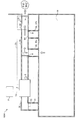
- FIG. 1 is a view showing an overall configuration of a duct type air conditioner according to a first embodiment.
- the air conditioner includes a heat exchanger and a blower fan, which will be described later, and is configured to take in air from the suction port and send out the air after air conditioning from the blowout port.
- the duct type air conditioner 100 is composed of an outdoor unit A and an indoor unit a, and the indoor unit a of the duct type air conditioner 100 is connected by a duct to the room to be the air conditioned space R.
- the ducts are an air conditioning main duct 30 disposed on a ceiling or wall of a building, an outflow duct 31 (exhaust duct) for taking in air from the air conditioned space R to the air conditioner side, and air conditioned in the air conditioned space R And an inflow duct 32 (32a, 32b) (air conditioning duct) for feeding the Moreover, the duct has an exhaust duct 33 connected to the outside of the building separately from the outflow duct 31 and the inflow duct 32.
- the indoor unit a is a first connection portion 35 which is a connection portion between the main duct 30 and the outflow duct 31 (exhaust duct), and a second connection portion which is a connection portion between the main duct 30 and the inflow duct 32a (air conditioning duct). 36a (36) is disposed between.
- the discharge mechanism 110 of the present embodiment is configured to include the discharge duct 33, the switching damper 9, and the duct fan 5.
- the exhaust duct 33 is connected to the main duct 30 on the upstream side of the inflow duct 32 at the downstream side of the indoor unit a and the third connecting portion 37.
- the exhaust duct 33 is provided with a duct fan 5 for blowing air to the outside of the building.
- the discharge duct 33 is provided at a position closer to the indoor unit a than the inflow duct 32.
- the duct connected to the indoor unit a is connected to the discharge duct 33 at the first branch point.
- no damper is provided in the inflow duct 32, and the switching damper 9 is provided only in the discharge duct 33.
- the switching damper 9 is connected to an actuator 8 that controls the opening and closing of the damper.
- the switching damper 9 fully closes air flow to the discharge duct 33 and fully opens air flow to the inflow duct 32 connected to the main duct 30 (in a normal state).
- the air flow to the discharge duct 33 can be fully opened, and the air flow to the inflow duct 32 can be completely closed in the second state (at the time of leakage).
- the indoor unit a or the main duct 30 is provided with a refrigerant detection sensor D (refrigerant leakage detection means) that detects refrigerant leakage. For example, it is provided in the vicinity of the blowout side of the indoor unit a of the air conditioner.
- a refrigerant detection sensor D refrigerant leakage detection means
- the refrigerant detection sensor D, the actuator 8 and the duct fan 5 are electrically connected to a control device (for example, the control unit 24 and see FIG. 3) of the duct type air conditioner 100, and are controlled according to the operating state.
- a control device for example, the control unit 24 and see FIG. 3
- slightly flammable (A2L) refrigerants such as R32, R1234yf and R1234ze are used.
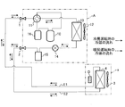
- FIG. 2 is a diagram showing a refrigeration cycle configuration of the duct type air conditioner.
- the multi-type air conditioner (multi-air conditioner) is composed of a gas-side refrigerant pipe E1 and a liquid-side refrigerant pipe E2 that connect one outdoor unit A with a plurality of indoor units a and units.
- the case of one indoor unit a will be described as an example.
- the gas side refrigerant pipe E1 and the liquid side refrigerant pipe E2 supply the refrigerant to the indoor unit a.
- the gas side refrigerant pipe E1 to the outdoor gas side block valve 1 of the outdoor unit A and connecting the liquid side refrigerant pipe E2 to the outdoor liquid side block valve 2 of the outdoor unit A, one refrigeration cycle system is configured. ing.
- the indoor unit a includes the indoor blower 3 and the indoor heat exchanger 4.
- the indoor unit a may be an indoor unit (package air conditioner) having a pressure reducing device (expansion valve) inside the unit. Further, the refrigerant detection sensor D is attached in the vicinity of the indoor unit a (in this example, in the vicinity of the indoor heat exchanger 4).
- the outdoor unit A includes a compressor 10, a four-way valve 11, an outdoor blower 12, an outdoor heat exchanger 13, an expansion valve 14, a refrigerant tank 15, and an accumulator 16.
- the arrows indicate the direction of the refrigerant flowing through the refrigerant pipe, the solid arrows indicate the cooling operation, and the reverse broken arrows indicate the heating operation.
- the flow direction of the refrigerant is determined by switching of the four-way valve 11 in the outdoor unit A.
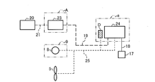
- FIG. 3 is a diagram showing a control system configuration of the duct type air conditioner.
- the control unit 23 of the outdoor unit A is connected to the central management control device 20 via the communication line 21, and is connected to the indoor unit a via the communication line 19.
- the control unit 24 of the indoor unit a is connected to the refrigerant detection sensor D, the actuator 8 and the duct fan 5 via the communication line 25.
- the remote control 17 air conditioning control terminal
- the remote control 17 is a remote control that gives control commands (setting of operation / stop, operation mode, temperature, air volume / wind direction, etc.) to the indoor unit a, and is connected with the indoor unit a by a remote control line 18 It is done.
- one control system is configured.
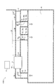
- FIG. 4 is a view showing the state of the damper after detecting the refrigerant leakage according to the first embodiment.
- the first state (normal time) of the switching damper 9 is shown in FIG. 1, and FIG. 4 shows the second state (time of leakage).
- the control unit 24 switches the switching damper 9 to the main duct 30 side and operates the duct fan 5 (fan) installed in the discharge duct 33 when refrigerant leakage is detected by the refrigerant detection sensor D (refrigerant leakage detection means). Discharge the refrigerant that has leaked to the outside.
- the refrigerant detection sensor D refrigerant leakage detection means
- an opening and closing damper may be provided on the discharge duct 33 side and the inflow duct 32 side, respectively.
- the open / close damper is provided on the main duct 30 downstream of the branch point of the discharge duct 33 and on the upstream side of the inflow duct 32, the number of dampers can be reduced.
- the control unit 24 also transmits a refrigerant leakage detection signal to the remote control 17 via the remote control line 18 and to the outdoor unit A via the communication line 19. Then, the controller 23 of the outdoor unit A transmits a refrigerant leakage detection signal to the central management control device 20 located above. By this, it is preferable to display a warning of “indoor unit a: refrigerant leakage” on the central management control device 20 or the remote controller 17 of the upper level.
- the duct type air conditioner 100 of 1st Embodiment is the outflow which connects the main duct 30 for air conditioning arrange
- a discharge mechanism 110 connected to the duct 30 and connected to the outside, and a control unit 24 (control device) for controlling the indoor unit a are provided.
- the control device can discharge the refrigerant leaked through the discharge mechanism 110 to the outside when the refrigerant leak detection unit detects the refrigerant leak.
- the refrigerant leak detection unit detects the refrigerant leak.
- the discharge mechanism 110 is connected to the main duct 30 on the downstream side of the indoor unit a and on the upstream side of the air conditioning duct, and covers the discharge duct 33 connected to the outside and the discharge duct at all times.
- the switching damper 9 closes the main duct 30 and the duct fan 5 (fan) installed in the discharge duct 33.
- the control device (control unit 24) switches the switching damper 9 to the main duct 30 side when refrigerant leakage is detected by the refrigerant leakage detection means, operates the fan installed in the exhaust duct, and discharges the leaked refrigerant to the outside You can drive.
- the blower compensates the shortage of the displacement due to the blowing of the indoor blower 3 of the indoor unit a, and can discharge the refrigerant to the outside at an early stage.
- control device When the control device (control unit 24) receives a detection signal from the refrigerant leakage detection means (the refrigerant detection sensor D), the switching damper 9 is switched so as to fully close the main duct, and the duct fan 5 is activated. Control.
- the refrigerant leaked into the duct does not flow to the inflow duct 32 side, flows into the exhaust duct 33, and is led to the outside of the building by the duct fan 5.
- the refrigerant leaked into the main duct 30 can be discharged to the outside of the building without flowing into the conditioned space R.
- the indoor fan 3 is provided also in the indoor unit a of the air conditioner, it is desirable that the duct fan 5 be provided in order to promote the exhaust when the discharge duct 33 is long.
- the duct type air conditioner 100 of this embodiment is applicable also when a room is plural.
- FIG. 5 is a diagram showing an overall configuration of a duct type air conditioner according to a second embodiment.
- the second embodiment is different from the first embodiment in the position of the discharge duct 33.
- the discharge duct 33 is provided at a position distant from the indoor unit a in the extension line of the main duct 30.
- a duct connected to the indoor unit a is connected to a discharge duct 33 at a branch point with the inflow duct 32b.
- the discharge mechanism 110 includes a discharge duct 33, a switching damper 9A, a switching damper 7, and a duct fan 5.
- the switching damper 7 may not be included in the discharge mechanism 110.
- the switching damper 9A completely closes the flow of air to the side of the discharge duct 33 connected to the main duct 30, and the flow of air to the side of the inflow duct 32b (air conditioning duct) connected to the main duct 30.
- the switching damper 9A is connected to an actuator 8 that controls the opening and closing of the damper.
- the switching damper 7 has a first state (normal time) in which circulation of air to the side of the inflow duct 32a connected to the main duct 30 is fully opened and a second state in which air to the inflow duct 32a is completely closed. It is possible to switch control to (the time of leakage) and the third state (at the time of leakage) in which the flow of air on the main duct 30 side is completely closed and the flow of air from the inflow duct 32a side is fully open. .
- the switching damper 7 is connected to an actuator 6 that controls the opening and closing of the damper.
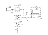
- FIG. 6 is a diagram showing a control system configuration of the air conditioner according to the second embodiment.
- the control unit 24 of the indoor unit a is connected to the refrigerant detection sensor D, the actuators 6 and 8, and the duct fan 5 via the communication line 25.
- the control unit 24 controls the switching dampers 7 and 9A in the first state as shown in FIG. 5 during normal operation. That is, the switching damper 7 fully opens air flow to the inflow duct 32 a side, the switching damper 9 A fully closes air flow to the discharge duct 33 side, and the inflow duct connected to the main duct 30. Air circulation to 32b (air conditioning duct) side is completely opened.
- the duct fan 5 is in a stopped state.
- the conditioned air is sent out from the indoor unit a, passes through the inflow ducts 32a and 32b, and is sent out to the conditioned space R.
- the air that has passed through the conditioned space R is taken into the indoor unit a via the outflow duct 31.
- FIG. 7 is a view showing the state of the damper after detecting the refrigerant leakage according to the second embodiment.
- the controller 24 (control device) switches the switching damper 9A to the inflow duct 32b (air conditioning duct) in the second state when refrigerant leakage is detected by the refrigerant detection sensor D (refrigerant leakage detection means), The switching damper 7 fully closes the air to the inflow duct 32a in the second state.
- the ducted fan 5 (fan) installed in the discharge duct 33 is operated to discharge the leaked refrigerant to the outside.
- the refrigerant leaked into the duct does not flow to the inflow ducts 32a and 32b, flows into the exhaust duct 33, and is led to the outside of the building by the duct fan 5. Thereby, the refrigerant leaked into the duct can be discharged to the outside of the building without flowing into the conditioned space R.
- a blower fan is provided also in the indoor unit a, it is desirable that the duct fan 5 be also provided in order to promote the exhaust when the discharge duct 33 is long.
- FIG. 8 is a view showing another example of the state of the damper after detecting the refrigerant leakage according to the second embodiment.
- the state of the damper shown in FIG. 8 is a state after a predetermined time has elapsed from the state of the damper shown in FIG. Refer to FIG. 5 and FIG. 6 as appropriate.
- the control unit 24 (control device) completely shuts off the flow of air on the main duct 30 side in the third state in the switching damper 7 when refrigerant leakage is detected by the refrigerant detection sensor D (refrigerant leakage detection means).
- the indoor fan 3 of the indoor unit a is stopped. Thereby, the ventilation operation of the air conditioned space R can be performed. Since the ventilation operation can be performed from the side of the inflow duct 32a close to the side of the discharge duct 33 instead of the outflow duct 31, the ventilation of the conditioned space R can be performed efficiently.
- the discharge mechanism 110 in the second embodiment closes the discharge duct 33 connected to the main duct 30 and connected to the outside and the discharge duct 33 at all times, and the refrigerant detection sensor D (refrigerant leakage detection means) leaks the refrigerant.
- the refrigerant detection sensor D refrigerant leakage detection means
- the control device switches the switching damper 9A to the air conditioning duct side and operates the fan installed in the discharge duct 33 when the refrigerant leakage is detected by the refrigerant leakage detection means (the refrigerant detection sensor D).
- the refrigerant can be discharged to the outside.
- the discharge process at the time of refrigerant leakage can be properly performed.
- another discharge mechanism 110 has a discharge duct 33 connected to the main duct 30 and connected to the outside, and the inflow duct 32 (air conditioning duct) is between the indoor unit a and the discharge duct 33. It has an inflow duct 32a (first air conditioning duct) close to the indoor unit a and an inflow duct 32b (second air conditioning duct) far from the indoor unit a, and always opens the first air conditioning duct, and the refrigerant leak detection means
- the refrigerant detection sensor D detects a refrigerant leakage
- the first switching damper 7 for closing the first air conditioning duct or the main duct 30 and the discharge duct 33 at all times
- the refrigerant leakage detection means for refrigerant leakage
- it detects it has the 2nd switching damper 9A which closes a 2nd air conditioning duct, and the duct fan 5 (fan) installed in the exhaust duct.
- the control device switches the first switching damper to close the first air conditioning duct and detects the second switching damper to the second air conditioning duct side when refrigerant leakage detection means detects refrigerant leakage. It is possible to switch the refrigerant installed in the discharge duct 33 by operating the fan to discharge the leaked refrigerant to the outside. Thus, the discharge process at the time of refrigerant leakage can be properly performed.
- the control device can switch the first switching damper to the main duct 30 side and operate the blower installed in the discharge duct 33 to perform the indoor ventilation operation. Thereby, after the discharge process at the time of refrigerant
- the discharge mechanism 110 is not necessarily limited to this.
- the switching damper 9A may be omitted, and the duct fan 5 may be provided with a shutter that opens with wind pressure. Since the shutter is normally closed, air from the indoor unit a is blown through the inflow duct 32. Further, when the refrigerant leaks, the duct fan 5 is activated to discharge the air including the refrigerant in the duct to the outside.
- the inflow duct 32 is not closed, when the exhaust capacity of the duct fan 5 is large, the air including the refrigerant can be discharged outdoors without flowing into the conditioned space R. If the duct volume of the discharge duct 33 of FIG. 1 is not large, the switching damper 9 may be omitted and the duct fan 5 may be provided with a shutter that opens with wind pressure.
- the control device may notify that the window or door of the air conditioned space R is to be opened via the remote control 17 (air conditioning control terminal) (see FIG. 6) connected to the indoor unit a. This notification may be applied also to the refrigerant leak detection shown in FIG.
Landscapes
- Engineering & Computer Science (AREA)
- Mechanical Engineering (AREA)
- General Engineering & Computer Science (AREA)
- Chemical & Material Sciences (AREA)
- Combustion & Propulsion (AREA)
- Physics & Mathematics (AREA)
- Thermal Sciences (AREA)
- Air Conditioning Control Device (AREA)
- Central Air Conditioning (AREA)
- Ventilation (AREA)
Abstract
ダクト式空気調和機は、室内機(a)またはメインダクト(30)内に設置した冷媒の漏洩を検知する冷媒検知センサ(D)と、室内機(a)の下流側で、かつ、流入ダクト(32)の上流側で、メインダクト(30)と連結されるとともに屋外と繋がる排出ダクト(33)と、常時は排出ダクト(33)を塞ぎ、冷媒検知センサ(D)が冷媒漏洩を検知した際に、メインダクト(30)を塞ぐ切換えダンパ(9)を有している。制御装置は、冷媒検知センサ(D)で冷媒漏洩を検知した場合に、切換えダンパ(9)をメインダクト30側に切換え、排出ダクト33に設置したダクトファン5を運転して漏洩した冷媒を屋外へ排出運転を行う。
Description
本発明は、ダクト式空気調和機に関する。
地球温暖化防止のため、冷凍空調機器に使用する冷媒のGWP(Global Warming Potential;地球温暖化係数)値低減が求められている。GWP値が低い冷媒は、微燃性(可燃性)を有することとなるため、微燃性を有するA2L冷媒を安全に使用するために冷媒漏洩に備えた安全対策を求める法律、規格が制定されている。
換気空調機能を有する利用側空調装置およびそれを備えた空調装置において、冷媒の漏洩が発生した場合に、漏洩した冷媒を速やかに排出して被空調空間に供給されないようにすることが提案されている(特許文献1参照)。
特許文献1には、「ケーシングと、ケーシング内に設けられており、熱源側空調装置から供給される冷媒によってケーシング内の空気を冷却または加熱する利用側熱交換器と、被空調空間からケーシングに室内空気を取り入れ、被空調空間外からケーシングに室外空気を取り入れ、ケーシング内の空気を被空調空間に供給空気として供給し、ケーシング内の空気を被空調空間外に排出空気として排出する給排気機構と、冷媒を検知する冷媒漏洩検知装置と、を有しており、冷媒漏洩検知装置が冷媒を検知した際に、給排気機構によってケーシング内の空気とともに冷媒を被空調空間外に排出する冷媒排出運転を行う利用側空調装置」が記載されている。
特許文献1は、冷媒漏洩検知装置が冷媒を検知した際には、給排気機構によってケーシング内の空気とともに冷媒を被空調空間外に排出する冷媒排出運転を行い、給排気機構を構成する第1排気送風機を運転することによって、冷媒排出運転を行うようにしている。しかしながら、被空調空間である室内と、ケーシングとはダクトで連通しているので、冷媒が入る虞がある(段落0059参照)。これに対処するため、室内との連通ダクトに給気防止機構が設けられているが(段落0093参照)、冷媒排出運転時の排気系統が複雑化するものとなっている。
本発明は、前記の課題を解決するための発明であって、冷媒漏洩時の冷媒の排出処理を的確に行うことができるダクト式空気調和機を提供することを目的とする。
前記目的を達成するため、本発明のダクト式空気調和機は、建物の天井または壁に配置される空調用のメインダクト(例えば、メインダクト30)と、メインダクトと室内(例えば、被空調空間R)とを連結する排気ダクト(例えば、流出ダクト31)および空調ダクト(例えば、流入ダクト32)と、メインダクトと排気ダクトとの連結部である第1連結部と、メインダクトと空調ダクトとの連結部である第2連結部との間に配置される空気調和機の室内機(例えば、室内機a)と、室内機からの冷媒の漏洩を検知する冷媒漏洩検知手段(例えば、冷媒検知センサD)と、室内機の下流側で、メインダクトと連結されるとともに屋外と繋がる排出機構(例えば、排出ダクト33、切換えダンパ9、ダクトファン5)と、室内機を制御する制御装置(例えば、制御部24)と、を備え、制御装置は、冷媒漏洩検知手段で冷媒漏洩を検知した場合に、排出機構を介して漏洩した冷媒を屋外へ排出運転を行うことを特徴とする。本発明のその他の態様については、後記する実施形態において説明する。
本発明によれば、冷媒漏洩時の冷媒の排出処理を的確に行うことができる。
本発明を実施するための実施形態について、適宜図面を参照しながら詳細に説明する。
<第1実施形態>
図1は、第1実施形態に係るダクト式空気調和機の全体構成を示す図である。空気調和機は、後記する熱交換器と送風ファンとを備え、吸込口から空気を取り込み、空調した後の空気を吹出口から送り出すように構成されている。ダクト式空気調和機100は、室外機Aと室内機aとで構成されており、ダクト式空気調和機100の室内機aは、被空調空間Rとなる室内とダクトで繋がっている。
<第1実施形態>
図1は、第1実施形態に係るダクト式空気調和機の全体構成を示す図である。空気調和機は、後記する熱交換器と送風ファンとを備え、吸込口から空気を取り込み、空調した後の空気を吹出口から送り出すように構成されている。ダクト式空気調和機100は、室外機Aと室内機aとで構成されており、ダクト式空気調和機100の室内機aは、被空調空間Rとなる室内とダクトで繋がっている。
ダクトは、建物の天井または壁に配置される空調用のメインダクト30と、被空調空間Rから空気調和機側に空気を取り込む流出ダクト31(排気ダクト)と、被空調空間Rに空調した空気を送る流入ダクト32(32a,32b)(空調ダクト)とで構成される。また、ダクトは、流出ダクト31と流入ダクト32とは別に、建物外部と繋がった排出ダクト33を有する。
室内機aは、メインダクト30と流出ダクト31(排気ダクト)との連結部である第1連結部35と、メインダクト30と流入ダクト32a(空調ダクト)との連結部である第2連結部36a(36)との間に配置されている。
本実施形態の排出機構110は、排出ダクト33、切換えダンパ9、ダクトファン5を含んで構成されている。排出ダクト33は、室内機aの下流側で、かつ、流入ダクト32の上流側のメインダクト30と第3連結部37で連結されている。排出ダクト33には、建物外部側へ送風するダクトファン5が設けられている。
本実施形態では、流入ダクト32よりも室内機aに近い位置に排出ダクト33が設けられている。言い換えれば、室内機aに接続されたダクトが最初の分岐点で排出ダクト33に接続されている。本実施形態では、流入ダクト32にはダンパを設けず、排出ダクト33だけに切換えダンパ9を設けている。切換えダンパ9は、ダンパの開閉を制御するアクチュエータ8が連結されている。
切換えダンパ9は、排出ダクト33側への空気の流通を全閉、かつ、メインダクト30に連結されている流入ダクト32側への空気の流通を全開とする第1の状態(通常時)と、排出ダクト33側への空気の流通を全開、かつ、流入ダクト32側への空気の流通を全閉とする第2の状態(漏洩時)と、に切換え制御することができる。
室内機aまたはメインダクト30には、冷媒漏洩を検知する冷媒検知センサD(冷媒漏洩検知手段)が設けられる。例えば、空気調和機の室内機aの吹出側の近傍に位置するように設けられる。
冷媒検知センサD、アクチュエータ8、ダクトファン5は、ダクト式空気調和機100の制御装置(例えば、制御部24、図3参照)と電気的に接続され、運転状態に応じて制御される。室外機Aと室内機aを循環する冷媒には、R32、R1234yfおよびR1234zeなどの微燃性(A2L)冷媒が用いられる。
図2は、ダクト式空気調和機の冷凍サイクル構成を示す図である。マルチ型の空気調和機(マルチエアコン)では、1台の室外機Aと複数台の室内機aおよび各ユニットを接続するガス側冷媒配管E1、液側冷媒配管E2で構成されている。ここでは、室内機aがひとつの場合を例として説明する。
ガス側冷媒配管E1と液側冷媒配管E2は、室内機aに冷媒を供給する。室外機Aの室外ガス側阻止弁1にガス側冷媒配管E1を接続し、室外機Aの室外液側阻止弁2に液側冷媒配管E2を接続することで、1つの冷凍サイクル系統を構成している。
室内機aは、室内送風機3、室内熱交換器4で構成されている。なお、室内機a内に、機内に減圧装置(膨張弁)を有する室内機(パッケージエアコン)であってもよい。また、冷媒検知センサDは室内機aの近傍(この例では、室内熱交換器4の近傍)に取り付けられる。
室外機Aにおいては、圧縮機10、四方弁11、室外送風機12、室外熱交換器13、膨張弁14、冷媒タンク15、アキュームレータ16で構成されている。矢印は冷媒配管を流れる冷媒の方向を示し、実線矢印が冷房運転で、逆向きの破線矢印が暖房運転を示す。この冷媒の流れ方向は、室外機A内の四方弁11の切り替えにより決められる。
図3は、ダクト式空気調和機の制御システム構成を示す図である。室外機Aの制御部23は、通信線21を介して集中管理制御機器20と接続されており、通信線19を介して室内機aと接続されている。室内機aの制御部24は、通信線25を介して、冷媒検知センサD、アクチュエータ8、ダクトファン5と接続されている。さらに、リモコン17(空調制御端末)は、室内機aに制御指令(運転/停止、運転モード、温度、風量/風向などの設定)を与えるリモコンであり、室内機aとはリモコン線18で接続されている。これにより、1つの制御システムを構成している。
図4は、第1実施形態に係る冷媒漏洩を検知した後のダンパの状態を示す図である。切換えダンパ9の前記した第1の状態(通常時)は図1に示し、図4は前記した第2の状態(漏洩時)を示す。制御部24は、冷媒検知センサD(冷媒漏洩検知手段)で冷媒漏洩を検知した場合に、切換えダンパ9をメインダクト30側に切換え、排出ダクト33に設置したダクトファン5(送風機)を運転して漏洩した冷媒を屋外へ排出運転を行う。
本実施形態は、ダンパが1つであるシンプルな構成とすることで、各流入ダクト32にダンパを設けなくとも冷媒漏洩時に被空調空間Rへの冷媒の漏れを抑制して、漏洩した冷媒を建物外部へ排出することができる。したがって、漏洩時の対策を低コストで実現することができる。
なお、切換えダンパ9で、排出ダクト33側と流入ダクト32側との開閉を行っているが、排出ダクト33側と流入ダクト32側とにそれぞれ開閉ダンパを設けてもよい。その際、排出ダクト33の分岐点の下流側で、かつ、流入ダクト32の上流側のメインダクト30に開閉ダンパを設けると、ダンパの個数を減らすことが可能である。
また、制御部24は、冷媒漏洩の検知信号を、リモコン線18を介してリモコン17に送信するとともに、通信線19を介して室外機Aに送信する。そして、室外機Aの制御部23から上位の集中管理制御機器20に冷媒漏洩の検知信号を送信する。これにより、上位の集中管理制御機器20やリモコン17に「室内機a:冷媒漏洩」という警告を表示するとよい。
以上、第1実施形態のダクト式空気調和機100は、建物の天井または壁に配置される空調用のメインダクト30と、メインダクト30と室内(例えば、被空調空間R)とを連結する流出ダクト31(排気ダクト)および流入ダクト32(空調ダクト)と、メインダクト30と排気ダクトとの連結部である第1連結部35と、メインダクト30と空調ダクトとの連結部である第2連結部36との間に配置される空気調和機の室内機aと、室内機aからの冷媒の漏洩を検知する冷媒検知センサD(冷媒漏洩検知手段)と、室内機aの下流側で、メインダクト30と連結されるとともに屋外と繋がる排出機構110と、室内機aを制御する制御部24(制御装置)と、を備えている。制御装置は、冷媒漏洩検知手段で冷媒漏洩を検知した場合に、排出機構110を介して漏洩した冷媒を屋外へ排出運転を行うことができる。これにより、冷媒漏洩時、冷媒の混ざった空気を屋外に排出することで室内の冷媒濃度が可燃濃度下限値以上になることを防止することができる。
排出機構110は、室内機aの下流側で、かつ、空調ダクトの上流側で、メインダクト30と連結されるとともに屋外と繋がる排出ダクト33と、常時は排出ダクトを塞ぎ、冷媒漏洩検知手段(冷媒検知センサD)が冷媒漏洩を検知した際に、メインダクト30を塞ぐ切換えダンパ9と、排出ダクト33に設置したダクトファン5(送風機)と、を備えている。制御装置(制御部24)は、冷媒漏洩検知手段で冷媒漏洩を検知した場合に、切換えダンパ9をメインダクト30側に切換え、排出ダクトに設置した送風機を運転して漏洩した冷媒を屋外へ排出運転を行うことができる。送風機は、室内機aの室内送風機3の送風による排気量の不足を補い、早期に冷媒を屋外へ排出することができる。
制御装置(制御部24)は、冷媒漏洩検知手段(冷媒検知センサD)から検知信号を受信すると、切換えダンパ9を、メインダクトを全閉するように切換え、ダクトファン5を起動させた状態に制御する。ダクト内に漏洩した冷媒は、流入ダクト32側には流れずに排出ダクト33へ流れ込み、ダクトファン5により建物外部へ導かれる。これにより、メインダクト30内に漏洩した冷媒を被空調空間Rに流入させることなく、建物外部へ排出することができる。なお、空気調和機の室内機a内にも室内送風機3が設けられているが、排出ダクト33が長い場合には排気を促進するためダクトファン5が設けられることが望ましい。なお、一部屋の例を示したが、部屋が複数の場合にも本実施形態のダクト式空気調和機100は、適用可能である。
<第2実施形態>
図5は、第2実施形態に係るダクト式空気調和機の全体構成を示す図である。第2実施形態は、排出ダクト33の位置が第1実施形態と異なる。第2実施形態では、メインダクト30の延長線で、室内機aに遠い位置に排出ダクト33が設けられている。室内機aに接続されたダクトが流入ダクト32bとの分岐点に排出ダクト33が接続されている。第1実施形態と同一要素には同一符号を付し重複する説明は省略する。
図5は、第2実施形態に係るダクト式空気調和機の全体構成を示す図である。第2実施形態は、排出ダクト33の位置が第1実施形態と異なる。第2実施形態では、メインダクト30の延長線で、室内機aに遠い位置に排出ダクト33が設けられている。室内機aに接続されたダクトが流入ダクト32bとの分岐点に排出ダクト33が接続されている。第1実施形態と同一要素には同一符号を付し重複する説明は省略する。
排出機構110は、排出ダクト33、切換えダンパ9A、切換えダンパ7、ダクトファン5を含んで構成されている。なお、流入ダクト32aがない被空調空間Rの場合には、切換えダンパ7は、排出機構110に含んでいなくてもよい。
切換えダンパ9Aは、メインダクト30に連結されている排出ダクト33側への空気の流通を全閉、かつ、メインダクト30に連結されている流入ダクト32b(空調ダクト)側への空気の流通を全開とする第1の状態(通常時)と、排出ダクト33側への空気の流通を全開、かつ、流入ダクト32b側への空気の流通を全閉とする第2の状態(漏洩時)と、に切換え制御することができる。切換えダンパ9Aは、ダンパの開閉を制御するアクチュエータ8が連結されている。
切換えダンパ7は、メインダクト30に連結されている流入ダクト32a側への空気の流通を全開とする第1の状態(通常時)と、流入ダクト32aへの空気を全閉する第2の状態(漏洩時)と、メインダクト30側の空気の流通を全閉、かつ、流入ダクト32a側からの空気の流通を全開とする第3の状態(漏洩時)と、に切換え制御することができる。切換えダンパ7は、ダンパの開閉を制御するアクチュエータ6が連結されている。
図6は、第2実施形態に係る空気調和機の制御システム構成を示す図である。図3に示す第1実施形態と同一要素には同一符号を付し重複する説明は省略する。室内機aの制御部24は、通信線25を介して、冷媒検知センサD、アクチュエータ6,8、ダクトファン5と接続されている。制御部24(制御装置)は、通常運転時において、図5に示すように、切換えダンパ7,9Aとも前記第1の状態に制御する。すなわち、切換えダンパ7を、流入ダクト32a側への空気の流通を全開とし、切換えダンパ9Aを、排出ダクト33側への空気の流通を全閉、かつ、メインダクト30に連結されている流入ダクト32b(空調ダクト)側への空気の流通を全開とする。また、ダクトファン5は停止させた状態である。空調した空気は室内機aから送り出され、流入ダクト32a,32bを通過して被空調空間Rに送り出される。被空調空間Rを通過した空気は流出ダクト31を介して室内機aに取り込まれる。
次に、冷媒漏洩を検知した後のダンパの状態を図7、図8で説明する。
図7は、第2実施形態に係る冷媒漏洩を検知した後のダンパの状態を示す図である。適宜、図5および図6を参照する。制御部24(制御装置)は、冷媒検知センサD(冷媒漏洩検知手段)で冷媒漏洩を検知した場合に、切換えダンパ9Aを前記第2の状態の流入ダクト32b(空調ダクト)側に切換えるとともに、切換えダンパ7を前記第2の状態の流入ダクト32aへの空気を全閉する。また、排出ダクト33に設置したダクトファン5(送風機)を運転して漏洩した冷媒を屋外へ排出運転を行う。
図7は、第2実施形態に係る冷媒漏洩を検知した後のダンパの状態を示す図である。適宜、図5および図6を参照する。制御部24(制御装置)は、冷媒検知センサD(冷媒漏洩検知手段)で冷媒漏洩を検知した場合に、切換えダンパ9Aを前記第2の状態の流入ダクト32b(空調ダクト)側に切換えるとともに、切換えダンパ7を前記第2の状態の流入ダクト32aへの空気を全閉する。また、排出ダクト33に設置したダクトファン5(送風機)を運転して漏洩した冷媒を屋外へ排出運転を行う。
ダクト内に漏洩した冷媒は、流入ダクト32a,32b側には流れずに排出ダクト33へ流れ込み、ダクトファン5により建物外部へ導かれる。これにより、ダクト内に漏洩した冷媒を被空調空間Rに流入させることなく、建物外部へ排出することができる。なお、室内機a内にも送風ファンが設けられているが、排出ダクト33が長い場合には排気を促進するためダクトファン5も設けられることが望ましい。
図8は、第2実施形態に係る冷媒漏洩を検知した後のダンパの状態の他の例を示す図である。図8に示すダンパの状態は、図7に示すダンパの状態から所定時間経過後の状態である。適宜、図5および図6を参照する。制御部24(制御装置)は、冷媒検知センサD(冷媒漏洩検知手段)で冷媒漏洩を検知した場合に、切換えダンパ7を前記第3の状態であるメインダクト30側の空気の流通を全閉し、室内機aの室内送風機3を停止する。これにより、被空調空間Rの換気運転を行うことができる。流出ダクト31に代えて、排出ダクト33側に近い流入ダクト32a側から換気運転ができるため、効率よい被空調空間Rの換気ができる。
以上、第2実施形態における排出機構110は、メインダクト30と連結されるとともに屋外と繋がる排出ダクト33と、常時は排出ダクト33を塞ぎ、冷媒検知センサD(冷媒漏洩検知手段)が冷媒漏洩を検知した際に、流入ダクト32(空調ダクト)を塞ぐ切換えダンパ9Aと、排出ダクト33に設置したダクトファン5(送風機)と、を備えている。制御装置(制御部24)は、冷媒漏洩検知手段(冷媒検知センサD)で冷媒漏洩を検知した場合に、切換えダンパ9Aを空調ダクト側に切換え、排出ダクト33に設置した送風機を運転して漏洩した冷媒を屋外へ排出運転を行うことができる。これにより、冷媒漏洩時の排出処理を的確に行うことができる。
第2実施形態に他の排出機構110は、メインダクト30と連結されるとともに屋外と繋がる排出ダクト33を有し、流入ダクト32(空調ダクト)は、室内機aと排出ダクト33との間に室内機aに近い流入ダクト32a(第1空調ダクト)と、室内機aに遠い流入ダクト32b(第2空調ダクト)を有しており、常時は第1空調ダクトを開放し、冷媒漏洩検知手段(冷媒検知センサD)が冷媒漏洩を検知した際に、第1空調ダクトを塞ぐまたはメインダクト30を塞ぐ第1切換えダンパ7と、常時は排出ダクト33を塞ぎ、冷媒漏洩検知手段が冷媒漏洩を検知した際に、第2空調ダクトを塞ぐ第2切換えダンパ9Aと、排出ダクトに設置したダクトファン5(送風機)と、を備えている。制御装置(制御部24)は、冷媒漏洩検知手段で冷媒漏洩を検知した場合に、第1切換えダンパを第1空調ダクトを塞ぐように切換え、かつ、第2切換えダンパを第2空調ダクト側に切換え、排出ダクト33に設置した送風機を運転して漏洩した冷媒を屋外へ排出運転を行うことができる。これにより、冷媒漏洩時の排出処理を的確に行うことができる。
制御装置は、所定時間経過後、第1切換えダンパを、メインダクト30側に切換え、排出ダクト33に設置した送風機を運転して室内の換気運転を行うことができる。これにより、冷媒漏洩時の排出処理後、被空調空間Rの換気処理を的確に行うことができる。
以上述べた実施形態において、排出機構110として、切換えダンパを含めた構成について説明した。しかし、排出機構110としては、必ずしもこれに限らない。例えば、図5において、切換えダンパ9Aを省略し、ダクトファン5が風圧で開くシャッターを設けてもよい。通常時、シャッターは閉じているため、室内機aからの送風は、流入ダクト32を介して送風される。また、冷媒漏洩時には、ダクトファン5が起動されてダクト内の冷媒を含む空気を屋外に排出することができる。この例では、流入ダクト32は閉じていないが、ダクトファン5の排出能力が大きい場合、冷媒を含む空気は被空調空間Rに流入することなく、屋外に排出することができる。図1の排出ダクト33のダクト容積が大きくない場合には、同様に、切換えダンパ9を省略し、ダクトファン5が風圧で開くシャッターを設けてもよい。
図8において、被空調空間Rの密閉度が高い場合、ダクトファン5を最大出力で駆動しても、換気ができない状態がある。この場合には、制御装置は、室内機aに接続されるリモコン17(空調制御端末)(図6参照)を介して、被空調空間Rの窓やドアを開ける旨を報知してもよい。この報知は、図7に示す冷媒漏洩検知時にも適用してもよい。
1 室外ガス側阻止弁
2 室外液側阻止弁
3 室内送風機
4 室内熱交換器
5 ダクトファン(送風機)
6,8 アクチュエータ
7 切換えダンパ(第1切換えダンパ)
9 切換えダンパ(第2切換えダンパ)
10 圧縮機
11 四方弁
12 室外送風機
13 室外熱交換器
14 膨張弁
15 冷媒タンク
16 アキュームレータ
17 リモコン
18 リモコン線
19 通信線(第1通信線)
20 集中管理制御機器
21 通信線
23 制御部
24 制御部(制御装置)
25 通信線(第2通信線)
30 メインダクト
31 流出ダクト(排気ダクト)
32 流入ダクト(空調ダクト
32a 流入ダクト(空調ダクト、第1空調ダクト)
32b 流入ダクト(空調ダクト、第2空調ダクト)
33 排出ダクト
35 第1連結部
36 第2連結部
37 第3連結部
100,100A ダクト式空気調和機
110 排出機構
A 室外機
a 室内機
D 冷媒検知センサ(冷媒漏洩検知手段)
E1 ガス側冷媒配管(冷媒配管、高低圧ガス冷媒配管、低圧ガス冷媒配管)
E2 液側冷媒配管(冷媒配管)
R 被空調空間
2 室外液側阻止弁
3 室内送風機
4 室内熱交換器
5 ダクトファン(送風機)
6,8 アクチュエータ
7 切換えダンパ(第1切換えダンパ)
9 切換えダンパ(第2切換えダンパ)
10 圧縮機
11 四方弁
12 室外送風機
13 室外熱交換器
14 膨張弁
15 冷媒タンク
16 アキュームレータ
17 リモコン
18 リモコン線
19 通信線(第1通信線)
20 集中管理制御機器
21 通信線
23 制御部
24 制御部(制御装置)
25 通信線(第2通信線)
30 メインダクト
31 流出ダクト(排気ダクト)
32 流入ダクト(空調ダクト
32a 流入ダクト(空調ダクト、第1空調ダクト)
32b 流入ダクト(空調ダクト、第2空調ダクト)
33 排出ダクト
35 第1連結部
36 第2連結部
37 第3連結部
100,100A ダクト式空気調和機
110 排出機構
A 室外機
a 室内機
D 冷媒検知センサ(冷媒漏洩検知手段)
E1 ガス側冷媒配管(冷媒配管、高低圧ガス冷媒配管、低圧ガス冷媒配管)
E2 液側冷媒配管(冷媒配管)
R 被空調空間
Claims (5)
- 建物の天井または壁に配置される空調用のメインダクトと、
前記メインダクトと室内とを連結する排気ダクトおよび空調ダクトと、
前記メインダクトと前記排気ダクトとの連結部である第1連結部と、前記メインダクトと前記空調ダクトとの連結部である第2連結部との間に配置される空気調和機の室内機と、
前記室内機からの冷媒の漏洩を検知する冷媒漏洩検知手段と、
前記室内機の下流側で、前記メインダクトと連結されるとともに屋外と繋がる排出機構と、
前記室内機を制御する制御装置と、を備え、
前記制御装置は、前記冷媒漏洩検知手段で冷媒漏洩を検知した場合に、前記排出機構を介して漏洩した冷媒を屋外へ排出運転を行う
ことを特徴とするダクト式空気調和機。 - 前記排出機構は、
前記室内機の下流側で、かつ、前記空調ダクトの上流側で、前記メインダクトと連結されるとともに屋外と繋がる排出ダクトと、
常時は前記排出ダクトを塞ぎ、前記冷媒漏洩検知手段が冷媒漏洩を検知した際に、前記メインダクトを塞ぐ切換えダンパと、
前記排出ダクトに設置した送風機と、を備え、
前記制御装置は、前記冷媒漏洩検知手段で冷媒漏洩を検知した場合に、前記切換えダンパを前記メインダクト側に切換え、前記排出ダクトに設置した前記送風機を運転して漏洩した冷媒を屋外へ排出運転を行う
ことを特徴とする請求項1に記載のダクト式空気調和機。 - 前記排出機構は、
前記メインダクトと連結されるとともに屋外と繋がる排出ダクトと、
常時は前記排出ダクトを塞ぎ、前記冷媒漏洩検知手段が冷媒漏洩を検知した際に、前記空調ダクトを塞ぐ切換えダンパと、
前記排出ダクトに設置した送風機と、を備え、
前記制御装置は、前記冷媒漏洩検知手段で冷媒漏洩を検知した場合に、前記切換えダンパを前記空調ダクト側に切換え、前記排出ダクトに設置した前記送風機を運転して漏洩した冷媒を屋外へ排出運転を行う
ことを特徴とする請求項1に記載のダクト式空気調和機。 - 前記排出機構は、
前記メインダクトと連結されるとともに屋外と繋がる排出ダクトを有し、
前記空調ダクトは、前記室内機と前記排出ダクトとの間に前記室内機に近い第1空調ダクトと、前記室内機に遠い第2空調ダクトを有しており、
常時は前記第1空調ダクトを開放し、前記冷媒漏洩検知手段が冷媒漏洩を検知した際に、前記第1空調ダクトを塞ぐまたは前記メインダクトを塞ぐ第1切換えダンパと、
常時は前記排出ダクトを塞ぎ、前記冷媒漏洩検知手段が冷媒漏洩を検知した際に、前記第2空調ダクトを塞ぐ第2切換えダンパと、
前記排出ダクトに設置した送風機と、を備え、
前記制御装置は、前記冷媒漏洩検知手段で冷媒漏洩を検知した場合に、前記第1切換えダンパを前記第1空調ダクトを塞ぐように切換え、かつ、前記第2切換えダンパを前記第2空調ダクト側に切換え、前記排出ダクトに設置した前記送風機を運転して漏洩した冷媒を屋外へ排出運転を行う
ことを特徴とする請求項1に記載のダクト式空気調和機。 - 前記制御装置は、所定時間経過後、
前記第1切換えダンパを、前記メインダクト側に切換え、前記排出ダクトに設置した前記送風機を運転して前記室内の換気運転を行う
ことを特徴とする請求項4に記載のダクト式空気調和機。
Priority Applications (2)
| Application Number | Priority Date | Filing Date | Title |
|---|---|---|---|
| PCT/JP2017/041100 WO2019097604A1 (ja) | 2017-11-15 | 2017-11-15 | ダクト式空気調和機 |
| JP2019554092A JP6851500B2 (ja) | 2017-11-15 | 2017-11-15 | ダクト式空気調和機 |
Applications Claiming Priority (1)
| Application Number | Priority Date | Filing Date | Title |
|---|---|---|---|
| PCT/JP2017/041100 WO2019097604A1 (ja) | 2017-11-15 | 2017-11-15 | ダクト式空気調和機 |
Publications (1)
| Publication Number | Publication Date |
|---|---|
| WO2019097604A1 true WO2019097604A1 (ja) | 2019-05-23 |
Family
ID=66539408
Family Applications (1)
| Application Number | Title | Priority Date | Filing Date |
|---|---|---|---|
| PCT/JP2017/041100 Ceased WO2019097604A1 (ja) | 2017-11-15 | 2017-11-15 | ダクト式空気調和機 |
Country Status (2)
| Country | Link |
|---|---|
| JP (1) | JP6851500B2 (ja) |
| WO (1) | WO2019097604A1 (ja) |
Cited By (6)
| Publication number | Priority date | Publication date | Assignee | Title |
|---|---|---|---|---|
| CN113639335A (zh) * | 2020-04-27 | 2021-11-12 | 青岛海尔智能技术研发有限公司 | 一种新风窗机空调 |
| CN114811844A (zh) * | 2022-04-19 | 2022-07-29 | 美的集团武汉暖通设备有限公司 | 空调器的运行控制方法、运行控制装置及空调器 |
| CN115076893A (zh) * | 2022-05-20 | 2022-09-20 | 青岛海尔空调器有限总公司 | 用于控制空调器的方法、装置及空调器、存储介质 |
| EP4123233A1 (en) | 2021-07-23 | 2023-01-25 | Mitsubishi Electric Corporation | Air-conditioning apparatus |
| CN116734392A (zh) * | 2023-07-24 | 2023-09-12 | 广东美的制冷设备有限公司 | 空调器的冷媒泄露处理方法、运行控制装置及空调器 |
| WO2024252670A1 (ja) * | 2023-06-09 | 2024-12-12 | 三菱電機株式会社 | 外気処理ユニットおよび空気調和機 |
Citations (3)
| Publication number | Priority date | Publication date | Assignee | Title |
|---|---|---|---|---|
| JPH0688638A (ja) * | 1992-04-13 | 1994-03-29 | Hitachi Ltd | 空気調和装置 |
| JP2004278923A (ja) * | 2003-03-17 | 2004-10-07 | Matsushita Electric Ind Co Ltd | 空気調和機 |
| JP2016196996A (ja) * | 2015-04-06 | 2016-11-24 | ダイキン工業株式会社 | 利用側空調装置及びそれを備えた空調装置 |
-
2017
- 2017-11-15 JP JP2019554092A patent/JP6851500B2/ja active Active
- 2017-11-15 WO PCT/JP2017/041100 patent/WO2019097604A1/ja not_active Ceased
Patent Citations (3)
| Publication number | Priority date | Publication date | Assignee | Title |
|---|---|---|---|---|
| JPH0688638A (ja) * | 1992-04-13 | 1994-03-29 | Hitachi Ltd | 空気調和装置 |
| JP2004278923A (ja) * | 2003-03-17 | 2004-10-07 | Matsushita Electric Ind Co Ltd | 空気調和機 |
| JP2016196996A (ja) * | 2015-04-06 | 2016-11-24 | ダイキン工業株式会社 | 利用側空調装置及びそれを備えた空調装置 |
Cited By (6)
| Publication number | Priority date | Publication date | Assignee | Title |
|---|---|---|---|---|
| CN113639335A (zh) * | 2020-04-27 | 2021-11-12 | 青岛海尔智能技术研发有限公司 | 一种新风窗机空调 |
| EP4123233A1 (en) | 2021-07-23 | 2023-01-25 | Mitsubishi Electric Corporation | Air-conditioning apparatus |
| CN114811844A (zh) * | 2022-04-19 | 2022-07-29 | 美的集团武汉暖通设备有限公司 | 空调器的运行控制方法、运行控制装置及空调器 |
| CN115076893A (zh) * | 2022-05-20 | 2022-09-20 | 青岛海尔空调器有限总公司 | 用于控制空调器的方法、装置及空调器、存储介质 |
| WO2024252670A1 (ja) * | 2023-06-09 | 2024-12-12 | 三菱電機株式会社 | 外気処理ユニットおよび空気調和機 |
| CN116734392A (zh) * | 2023-07-24 | 2023-09-12 | 广东美的制冷设备有限公司 | 空调器的冷媒泄露处理方法、运行控制装置及空调器 |
Also Published As
| Publication number | Publication date |
|---|---|
| JPWO2019097604A1 (ja) | 2020-10-01 |
| JP6851500B2 (ja) | 2021-03-31 |
Similar Documents
| Publication | Publication Date | Title |
|---|---|---|
| JP6851500B2 (ja) | ダクト式空気調和機 | |
| JP6849021B2 (ja) | 冷凍サイクルシステム | |
| US10488072B2 (en) | Air conditioning system with leak protection control | |
| CN110402360B (zh) | 冷冻装置的室内单元 | |
| US11118821B2 (en) | Refrigeration cycle apparatus | |
| US9459013B2 (en) | Air-conditioning apparatus with safety measure for ventilation of inflammable refrigerant from heat exchanger | |
| US10655884B2 (en) | Air conditioner | |
| JP6701444B2 (ja) | 空気調和システム及びその冷媒量設定方法 | |
| JP6929747B2 (ja) | 空気調和機 | |
| WO2017183234A1 (ja) | ヒートポンプ装置のファン駆動回路 | |
| EP3792565B1 (en) | Air conditioning system | |
| CN115349073A (zh) | 空调系统 | |
| CN104395678A (zh) | 空调装置 | |
| WO2012098581A1 (ja) | 空気調和装置 | |
| WO2017187483A1 (ja) | 室内機および空気調和装置 | |
| JP2023030640A (ja) | 空気調和装置 | |
| JP7315845B2 (ja) | 空気調和装置 | |
| JP7495594B2 (ja) | 空気調和システム | |
| JP7057519B2 (ja) | 空気調和システム | |
| CN113811729A (zh) | 空调系统 | |
| JP2021085642A (ja) | 空気調和装置 | |
| JP2025129293A (ja) | 空気調和装置 | |
| JP6448658B2 (ja) | 空気調和システム | |
| JP6914794B2 (ja) | 空気調和機 | |
| JP6778888B1 (ja) | 中継器及び空気調和装置 |
Legal Events
| Date | Code | Title | Description |
|---|---|---|---|
| 121 | Ep: the epo has been informed by wipo that ep was designated in this application |
Ref document number: 17932508 Country of ref document: EP Kind code of ref document: A1 |
|
| ENP | Entry into the national phase |
Ref document number: 2019554092 Country of ref document: JP Kind code of ref document: A |
|
| NENP | Non-entry into the national phase |
Ref country code: DE |
|
| 122 | Ep: pct application non-entry in european phase |
Ref document number: 17932508 Country of ref document: EP Kind code of ref document: A1 |