WO2019088237A1 - 液体材料塗布装置および塗布方法 - Google Patents
液体材料塗布装置および塗布方法 Download PDFInfo
- Publication number
- WO2019088237A1 WO2019088237A1 PCT/JP2018/040765 JP2018040765W WO2019088237A1 WO 2019088237 A1 WO2019088237 A1 WO 2019088237A1 JP 2018040765 W JP2018040765 W JP 2018040765W WO 2019088237 A1 WO2019088237 A1 WO 2019088237A1
- Authority
- WO
- WIPO (PCT)
- Prior art keywords
- stage
- axis
- coating
- discharge
- work
- Prior art date
Links
Images


Classifications
-
- B—PERFORMING OPERATIONS; TRANSPORTING
- B41—PRINTING; LINING MACHINES; TYPEWRITERS; STAMPS
- B41J—TYPEWRITERS; SELECTIVE PRINTING MECHANISMS, i.e. MECHANISMS PRINTING OTHERWISE THAN FROM A FORME; CORRECTION OF TYPOGRAPHICAL ERRORS
- B41J25/00—Actions or mechanisms not otherwise provided for
- B41J25/001—Mechanisms for bodily moving print heads or carriages parallel to the paper surface
- B41J25/006—Mechanisms for bodily moving print heads or carriages parallel to the paper surface for oscillating, e.g. page-width print heads provided with counter-balancing means or shock absorbers
-
- B—PERFORMING OPERATIONS; TRANSPORTING
- B05—SPRAYING OR ATOMISING IN GENERAL; APPLYING FLUENT MATERIALS TO SURFACES, IN GENERAL
- B05C—APPARATUS FOR APPLYING FLUENT MATERIALS TO SURFACES, IN GENERAL
- B05C5/00—Apparatus in which liquid or other fluent material is projected, poured or allowed to flow on to the surface of the work
- B05C5/02—Apparatus in which liquid or other fluent material is projected, poured or allowed to flow on to the surface of the work the liquid or other fluent material being discharged through an outlet orifice by pressure, e.g. from an outlet device in contact or almost in contact, with the work
- B05C5/0283—Flat jet coaters, i.e. apparatus in which the liquid or other fluent material is projected from the outlet as a cohesive flat jet in direction of the work
-
- B—PERFORMING OPERATIONS; TRANSPORTING
- B41—PRINTING; LINING MACHINES; TYPEWRITERS; STAMPS
- B41J—TYPEWRITERS; SELECTIVE PRINTING MECHANISMS, i.e. MECHANISMS PRINTING OTHERWISE THAN FROM A FORME; CORRECTION OF TYPOGRAPHICAL ERRORS
- B41J11/00—Devices or arrangements of selective printing mechanisms, e.g. ink-jet printers or thermal printers, for supporting or handling copy material in sheet or web form
- B41J11/02—Platens
- B41J11/06—Flat page-size platens or smaller flat platens having a greater size than line-size platens
-
- B—PERFORMING OPERATIONS; TRANSPORTING
- B41—PRINTING; LINING MACHINES; TYPEWRITERS; STAMPS
- B41J—TYPEWRITERS; SELECTIVE PRINTING MECHANISMS, i.e. MECHANISMS PRINTING OTHERWISE THAN FROM A FORME; CORRECTION OF TYPOGRAPHICAL ERRORS
- B41J11/00—Devices or arrangements of selective printing mechanisms, e.g. ink-jet printers or thermal printers, for supporting or handling copy material in sheet or web form
- B41J11/20—Platen adjustments for varying the strength of impression, for a varying number of papers, for wear or for alignment, or for print gap adjustment
-
- B—PERFORMING OPERATIONS; TRANSPORTING
- B41—PRINTING; LINING MACHINES; TYPEWRITERS; STAMPS
- B41J—TYPEWRITERS; SELECTIVE PRINTING MECHANISMS, i.e. MECHANISMS PRINTING OTHERWISE THAN FROM A FORME; CORRECTION OF TYPOGRAPHICAL ERRORS
- B41J25/00—Actions or mechanisms not otherwise provided for
- B41J25/304—Bodily-movable mechanisms for print heads or carriages movable towards or from paper surface
-
- B—PERFORMING OPERATIONS; TRANSPORTING
- B41—PRINTING; LINING MACHINES; TYPEWRITERS; STAMPS
- B41J—TYPEWRITERS; SELECTIVE PRINTING MECHANISMS, i.e. MECHANISMS PRINTING OTHERWISE THAN FROM A FORME; CORRECTION OF TYPOGRAPHICAL ERRORS
- B41J3/00—Typewriters or selective printing or marking mechanisms characterised by the purpose for which they are constructed
- B41J3/407—Typewriters or selective printing or marking mechanisms characterised by the purpose for which they are constructed for marking on special material
- B41J3/4073—Printing on three-dimensional objects not being in sheet or web form, e.g. spherical or cubic objects
-
- B—PERFORMING OPERATIONS; TRANSPORTING
- B05—SPRAYING OR ATOMISING IN GENERAL; APPLYING FLUENT MATERIALS TO SURFACES, IN GENERAL
- B05C—APPARATUS FOR APPLYING FLUENT MATERIALS TO SURFACES, IN GENERAL
- B05C13/00—Means for manipulating or holding work, e.g. for separate articles
- B05C13/02—Means for manipulating or holding work, e.g. for separate articles for particular articles
Definitions
- the present invention relates to a coating apparatus and a coating method capable of coating by tilting a stage for holding a coating target.
- Patent Document 1 discloses a liquid material application apparatus in which positioning of a work that discharges a liquid material is simplified by inclining a stage.
- this invention aims at providing the coating device which makes it possible to perform three-dimensional application
- the coating apparatus comprises a discharge head having a discharge device having a discharge port opening in the Z direction, a stage for holding a work, an XYZ relative movement device for relatively moving the discharge head and the stage, and XY An R-axis rotation device for rotating the stage about an R-axis parallel to a plane; a P-axis rotation device for rotating the stage about a P-axis parallel to the XY plane and different from the R-axis; A pedestal, wherein the P-axis rotation device is disposed below the R-axis rotation device, and the P-axis rotation device rotates the R-axis rotation device together with the stage. .
- the discharge head is not provided with a rotation mechanism for rotating the discharge device, it is possible to reduce the weight of the discharge head.
- the stage may be rotated by ⁇ 60 ° or more by the R-axis rotating device, and the stage may be rotated by ⁇ 60 ° or more by the P-axis rotating device.
- the stage may be rotated by ⁇ 90 ° by the R-axis rotating device, and the stage may be rotated by ⁇ 90 ° by the P-axis rotating device.
- the ⁇ 90 ° rotation includes a mode of rotating over ⁇ 90 °.
- the coating apparatus may be characterized in that it does not have a rotation mechanism for rotating the stage in the ⁇ direction.
- the maximum width L1 in the direction orthogonal to the R axis of the stage may be shorter than the maximum width L2 in the direction orthogonal to the P axis of the stage.
- the height H1 from the upper end of the member positioned below the side of the stage to the R rotation axis during operation of the R-axis rotation apparatus is configured to be a distance of half or more of the L1.
- the height H2 from the upper end of the member positioned below the side of the stage to the P rotation axis during operation of the P-axis rotation device is configured to be a distance of half or more of the L2 May be characterized.
- the gantry may be provided with a top plate having an open movable range of the stage and a stage movement space that allows the stage to rotate about the R axis and the P axis.
- the XYZ relative displacement device may be disposed on the top plate.
- the first relative movement device includes: two first direction movement devices disposed across the stage; a second direction movement device that bridges the two first direction movement devices; and the second direction It may be characterized by being comprised by the 3rd direction movement apparatus attached to the movement apparatus.
- the coating apparatus includes: a plurality of columns extending upward from the gantry; and a table installed on the gantry, wherein the R-axis rotating device and the P-axis rotating device are installed on the table And the XYZ relative movement device is attached to a first direction movement device for moving the table in a first direction, a second direction movement device supported by the plurality of columns, and the second direction movement device
- the present invention may be characterized by being configured by the third direction movement device.
- the discharge head may be mounted on the third direction moving device, and may not include a rotation mechanism for rotating the discharge device.
- the stage may be composed of a plurality of stages having different areas, and the selected one of the stages can hold the work to perform the coating operation.
- the discharge apparatus may be a jet-type discharge apparatus in which the valve body is moved forward and then stopped to apply an inertial force to the liquid material to fly and discharge it.
- the X, Y and Z relative movement devices move the discharge head and the stage relative to each other along the X direction straight line, the discharge head and the stage along the Y direction straight line.
- the apparatus comprises: a Y-direction moving device for moving relative to one another; and a Z-direction moving device for moving the discharge head and the stage relative to each other along a straight line in the Z direction.
- the coating method according to the first aspect of the present invention is a coating method for coating a workpiece on a stage using the above-described coating apparatus.
- the coating method according to the second aspect of the present invention is a coating method for coating a workpiece on a stage using the coating apparatus, wherein the R axis rotating device rotates the stage, and the R axis rotating device and the R axis rotating device A first side coating step of applying the first side surface of the work while stopping the P axis rotating device and keeping the clearance between the discharge device and the work constant; rotating the stage by the P axis rotating device A second side surface applying a second side surface intersecting the first side surface of the work while stopping the R-axis rotation device and the P-axis rotation device and keeping the clearance between the discharge device and the work constant; Coating step, and after the first side coating step is performed, the second side coating step is performed, or after the second side coating step is performed, the first side coating step is performed.
- the first side coating step A corner portion coating step carried out before implementation, and in the corner portion coating step, a radius continuous with the first side surface and the second side surface of the work while operating the R-axis rotation device and the P-axis rotation device It may be characterized in that coating is performed while maintaining a constant clearance between the discharge device and the work.
- the work may be sized to cover the stage.
- FIG. 2 is a cross-sectional view taken along line AA of FIG. It is CC sectional drawing of FIG. It is a figure explaining operation
- FIG. 2 is a cross-sectional view taken along the line BB in FIG. It is a figure (D arrow direction view of FIG. 2) explaining the coating operation performed by making a stage incline by R axis
- E arrow line view of FIG. 2 explaining the coating operation which makes a stage incline and is performed by a P-axis rotation apparatus. It is a figure for demonstrating the location which performs an application operation in the cover of a smart phone. It is an enlarged view for demonstrating the application
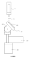
- the coating apparatus 100 includes a discharge device 1 for discharging a liquid material, a stage 21 on which an object to be coated (work) 20 is mounted, and a stage 21.
- a discharge device 1 for discharging a liquid material
- a stage 21 on which an object to be coated (work) 20 is mounted and a stage 21.
- R axis rotation device 22 to rotate the axis
- P axis rotation device 23 to rotate the stage 21 P axis
- XYZ relative movement devices 105, 106, 107) to move the discharge device 1 and the stage 21 relative to each other
- the control unit 112 is mainly configured to control.
- the stage 21 is a flat plate-like member having a flat surface on which the application target 20 is placed, and includes a fixing mechanism for fixing the application target (work) 20 to the stage 21.
- a fixing mechanism for example, a plurality of holes communicating from the inside of the stage 21 to the upper surface are opened, and a mechanism for sucking and fixing the application object 20 by sucking air from the holes;
- a mechanism or the like for fixing the application target 20 can be used by fixing the member to the stage 21 with fixing means such as screws.
- the stage 21 has a short side of the length L1 in the X direction (see FIG. 5) and a long side of the length L2 in the Y direction (see FIG. 6).
- the area of the work mounted on the stage 21 is preferably larger than the area of the stage 21, and more preferably the size that covers the entire surface of the stage 21 when viewed from above.
- the shape of the stage 21 is not limited to a rectangle, and may be a square, a polygon, or a circle.
- the XYZ relative movement device is configured of an X-direction drive device 105, a Y-direction drive device 106, and a Z-direction drive device 107 disposed on a gantry 101.
- the discharge device 1 is configured to be linearly moved relative to the stage 21 in the X direction (reference numeral 108), the Y direction (reference numeral 109), and the Z direction (reference numeral 110).
- the XYZ relative movement device moves the nozzle 2 of the discharge device 1 relative to the work on the stage 21 by a combination of linear movement in the X direction, linear movement in the Y direction, and linear movement in the Z direction. It is configured as follows.
- the X-direction drive device 105 is mounted to bridge the two Y-direction drive devices 106 a and 106 b, and the Z-direction drive device 107 is mounted to the X-direction drive device 105.
- the XYZ relative movement device 105, 106, 107
- a combination of an electric motor (servo motor, stepping motor or the like) and a ball screw, a linear motor or the like can be used.
- the Z-direction driving device 107 may be provided between the R-axis rotating device 22 and the P-axis rotating device 23 and the support plate 104.
- the control device 112 includes a processing device (not shown) and a storage device, and the discharge device 1, the R-axis rotation device 22, the P-axis rotation device 23 and the XYZ relative movement device (105, 106, 107) are connected , Control the operation of each of these devices.
- a personal computer (PC), a programmable logic controller (PLC), or the like can be used as the processing device and the storage device.
- PLC programmable logic controller
- the input / output device 113 capable of bi-directional communication with the control device 112, in addition to the touch panel shown, a keyboard, a mouse or the like can also be used.
- the storage device of the control device 112 stores an application program for realizing the application method of the present invention.
- the discharge device 1 of the first embodiment is a discharge type of the type in which the liquid material contacts the work before separating from the discharge port, and a discharge type of the type in which the liquid material contacts the work after the liquid material is separated from the discharge port. Can be adopted.
- a discharge method of a type in which the liquid material comes in contact with the work before separating from the discharge port an air-type, flat tubing mechanism or the like which applies air regulated to the liquid material in the syringe having a nozzle at the tip for a desired time.
- Tubing type with a rotary tubing mechanism Plunger type that displaces and discharges a plunger that slides closely to the inner surface of the storage container with a nozzle at the tip by a desired amount
- Screw type that discharges liquid material by screw rotation
- Desired pressure The valve type etc. which carry out discharge control of the liquid material to which it was applied by opening and closing of a valve are illustrated.
- the plunger As a discharge method of the type in which the liquid material comes in contact with the work after separating from the discharge port, the plunger (valve body) is moved forward and stopped rapidly to apply an inertia force to the liquid material to move from the tip of the nozzle
- a jet type, a continuous injection type, or a demand type ink jet type for flying and discharging is exemplified.
- the discharge device 1 is attached to the base plate 10 together with the imaging device 11 and the distance measurement device 12. That is, when the ejection device 1 is moved relative to the application target 20 by the XYZ relative movement device, the imaging device 11 and the distance measurement device 12 are also relatively moved integrally with the ejection device 1.
- the devices (1, 11 to 12) attached to the base plate 10 constitute the discharge head 4. Since the discharge head 4 is not provided with a rotation mechanism for rotating each device (1, 11 to 12), it is lighter in weight than a discharge head provided with a rotation mechanism.
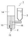
- FIG. 13 is a cross-sectional side view of relevant parts of the jet-type ejection device 1 that can be mounted on the coating device 100 according to the first embodiment.
- the discharge device 1 includes a nozzle 2, a liquid storage container 3, a discharge unit 13, and a discharge drive device 14.
- the discharge device 1 is provided with a plunger 16 in the liquid chamber of the discharge portion 13 communicating with the discharge port 15 of the nozzle 2 without contacting or partially contacting the side wall of the liquid chamber but not blocking the flow of the liquid material There is. Then, by advancing and retracting the plunger 16 at a high speed, it is possible to apply an inertial force to the liquid material and to discharge the liquid material in the form of droplets from the discharge port 15 of the nozzle 2.
- the discharge port 15 of the nozzle 2 opens in the Z direction (vertical direction).
- the discharge port 15 of the nozzle 2 has an end face parallel to the XY plane (see FIG. 13).
- the nozzle 2 is preferably constituted by a straight pipe whose center line extends in the Z direction (vertical direction).
- the coating operation is performed by providing a distance between the discharge port 15 of the nozzle 2 and the work (droplet is discharged and ejected), so the rotation operation of the R and P axes is performed. There is an allowance for the displacement of the distance between the discharge port 15 and the work that occurs.
- the coating operation is performed by providing a distance between the nozzle 2 and the work, the R-axis and P-axis rotation operations can be performed without raising the nozzle 2.
- the jet discharge device 1 While the operation of the XYZ relative movement device is stopped at the time of dot application in the discharge device of another discharge method, the jet discharge device 1 operates either one of the X direction drive device 105 and the Y direction drive device 106 Since the coating is performed in a continuous point manner, the productivity is excellent.
- the imaging device 11 is a digital camera such as a CCD camera. While viewing the image of the application target 20 captured by the imaging device 11, it is possible to perform a teaching operation to specify the application position.
- the distance measuring device 12 is a noncontact measuring device such as a laser displacement sensor that irradiates a workpiece with a laser beam and measures the distance to the workpiece surface. Unlike this, a contact-type measuring device may be employed which measures the distance to the workpiece surface by contacting the workpiece surface.
- the gantry 101 includes a top 102 having an opening 103 formed therein.
- the opening 103 has a size that secures the movable range of the stage 21, and the stage 21, the R-axis rotating device 22, the P-axis rotating device 23, and the utility unit 24 are disposed in the opening 103.
- a stage movement space 111 is provided below the opening 103 of the top plate 102 to enable rotational movement about the R axis and the P axis of the stage 21. If the stage movement space 111 can be secured, a support member for supporting the Y relative movement device 106 may be provided without providing the top plate 102.
- a cover with a door may be provided to cover a portion of the gantry 101 above the top plate 102.
- the R-axis rotating device 22 is a device that enables the stage 21 to rotate about an R-axis parallel to the Y movement direction 109. In other words, the R-axis rotating device 22 enables the stage 21 to be inclined to the left and right (first direction) about the R-axis.
- the R-axis rotating device 22 includes an R-axis rotating body 22 a that rotates around the R-axis, an R-axis rotating device (R-axis driving source) 22 b configured by an electric motor, etc. It comprises and comprises board 22c.
- the P-axis rotation device 23 is a device that enables the stage 21 to rotate about a P-axis orthogonal to the R-axis.
- the P-axis rotating device 23 enables the stage 21 to be tilted back and forth (a second direction orthogonal to the first direction) about the P-axis.
- the P-axis rotating device 23 is configured to include a P-axis rotating body 23a that rotates around the P-axis, and a P-axis rotating device (P-axis drive source) 23b configured by an electric motor or the like. It is fixed at 25.
- the R axis coincides with the Y direction, but the R axis does not have to coincide with the Y direction.
- the R axis and the P axis do not have to be orthogonal to each other as in the first embodiment, and for example, there may be a positional relationship in which the R axis and the P axis form an angle of 30 °, 45 ° or 60 °. .
- the R-axis rotating device 22 is disposed at substantially the same height as the top plate 102, and a stage movement space 111 is provided below the opening 103 of the top plate 102. Therefore, when the R-axis rotating device 22 is driven, the side 21a and 21b of the stage 21 can be rotated until reaching the vicinity of the base plate 22c (see FIG. 5). In other words, when the R-axis rotation device 22 is driven, the stage 21 in the horizontal position is rotated by ⁇ 60 ° or more (preferably ⁇ 75 ° or more, more preferably ⁇ 90 °) about the R-axis. Can.
- the P axis rotating device 23 ie, the P axis rotating device (P axis) located below the side of the stage 21 when rotating the R axis It is necessary to configure so that the height H1 from the upper end of the driving source 23b) to the R rotation shaft 22d is a distance of half or more of the length L1 of the short side of the stage 21 (see FIG. 5).
- the length L1 is the maximum width of the stage 21 in the P-axis direction (direction orthogonal to the R-axis).
- the heights of the Y-direction moving devices 106 a and 106 b can be lowered by installing the R-axis rotating device 22 at the height to be embedded in the top plate 102.
- the distance between the nozzle 2 and the stage 21 can be shortened, and the accuracy of the impact position of the droplet can be enhanced.
- the R-axis rotating device 22 and the P-axis rotating device 23 are supported by a support 25 disposed on a support plate 104 in the gantry 101. Since the stage movement space 111 is provided on the support plate 104, when the P-axis rotation device 23 is driven, the side 21 c and 21 d of the stage 21 is rotated until reaching the vicinity of the support 25. (See Figure 6). In other words, when the P-axis rotation device 23 is driven, the stage 21 (or R-axis rotation device 22) in the horizontal position is ⁇ 60 ° or more (preferably ⁇ 75 ° or more, preferably) around the P-axis. Can be rotated ⁇ 90 °).
- the utility unit 24 is installed on the support plate 104.
- the utility unit 24 includes a nozzle cleaning mechanism, a dumping stage, a clearance adjustment mechanism, and the like. As can be seen from FIG. 1, the utility unit 24 and the stage 21 are provided with the clearance necessary to rotate the stage 21 by the P-axis rotating device 23.
- FIG. 8 is a side view for explaining how coating is performed with the stage 21 tilted by the R-axis rotation device 22. As shown in FIG. By tilting the stage 21 by the R-axis rotating device 22, it becomes possible to apply the liquid material to the first side surface of the application target 20.
- FIG. 9 is a side view for explaining a state in which coating is performed with the stage 21 tilted by the P-axis rotation device 23. By tilting the stage 21 by the P-axis rotating device 23, it is possible to apply the liquid material to the second side orthogonal to the first side of the application target 20.
- the control device 112 has a function of performing coordinate conversion of the XYZ relative movement device (105, 106, 107), so the ⁇ axis rotating device for rotating the stage 21 by ⁇ axis is unnecessary. It is. Since the XY plane is the ⁇ rotation surface, ⁇ correction can be performed by coordinate conversion work. However, even if a ⁇ -axis rotation device for rotating the stage 21 by the ⁇ -axis is provided, it is possible to carry out the coating method of the present invention.
- FIG. 10 is a diagram for describing a portion where the application operation is performed in the work 20 which is a cover of the smartphone.
- the work 20 is sized to cover the stage 21.
- (B), (c), (d), (e), (e), (f), (g), (h) are drawn in order from (a) to perform coating work on the cover of the smartphone, and (a) The application drawing is completed by returning to).
- any method is applicable to the present invention.
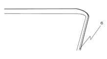
- FIG. 11 is an enlarged view for explaining the application area 6 which is a side surface of the cover of the smartphone of FIG.
- the application area 6 of this cover is a linear surface (a surface as if being chamfered) inclined downward and outward.
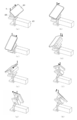
- FIG. 12 is a diagram for describing the procedure for performing the application operation in the cover of the smartphone. (A) to (h) of FIG. 12 correspond to (a) to (h) of FIG. In addition, in FIG. 12, the nozzle 2 is drawn larger than usual for convenience of explanation.
- the vertical and horizontal directions in the following (a) to (h) mean the vertical and horizontal directions in FIG.
- the workpiece left upper corner portion is a corner portion having a radius continuous with the first side surface and the second side surface.
- the stage is rotated to the front side by the P-axis rotating device 23 while rotating the stage to the left by the R-axis rotating device 22.
- the control device 112 synchronizes the rotation of the stage 21 by the R-axis rotating device 22 and the P-axis rotating device 23 with the operation of the XYZ relative moving device that controls the position of the nozzle 2 to paint and draw the corner of the workpiece 20 can do. As shown in FIG.
- the workpiece right upper corner portion is a corner portion having a radius continuous with the second side surface and the third side surface.
- the workpiece right lower corner portion is a corner portion having a radius continuous with the third side and the fourth side.
- the stage 21 is rotated to the right by the R-axis rotating device 22 while the stage 21 is rotated to the rear side by the P-axis rotating device 23.
- the control device 112 synchronizes the rotation of the stage 21 by the R-axis rotating device 22 and the P-axis rotating device 23 and the operation of the XYZ relative moving device that controls the position of the nozzle 2.
- (H) Lower left corner of workpiece (fourth corner)
- the lower left corner of the workpiece is a corner having a radius continuous with the fourth side and the first side.
- the stage 21 is rotated to the right by the R-axis rotating device 22 while the stage 21 is rotated to the near side by the P-axis rotating device 23.
- the control device 112 synchronizes the rotation of the stage 21 by the R-axis rotating device 22 and the P-axis rotating device 23 and the operation of the XYZ relative moving device that controls the position of the nozzle 2.
- the R-axis rotating device 22 and the P-axis rotating device 23 are at the same positions as in (a).
- drawing is performed up to the application start position, the application operation on one work 20 is completed.
- the coating device 100 according to the first embodiment described above can be used for adhesion of a case (main body) of a smartphone or coating work such as 3DM ID (3D Molded Interconnected Device). Moreover, it is utilized also for apply
- the stage can be rotated so that the circumferential surface is directed toward the discharge port of the nozzle, so a jig or the like for applying the workpiece while standing up is unnecessary. It is.
- all the portions other than facing the stage of the work are to be coated, it is possible to coat the side circumferential surface of the work without changing the posture of the work.
- the coating apparatus 200 includes, as shown in FIG. 14, a discharge device 1 for discharging a liquid material, a stage 21 for placing an object to be coated on its upper surface, and R for rotating the stage 21 by R axis.
- the same components as those in the first embodiment may be denoted by the same reference numerals and descriptions thereof may be omitted.
- the ejection device 1 is mounted on the Z-direction drive device 207, and the Z-direction drive device 207 is mounted on the X-direction drive device 205.
- the stage 21 located below the discharge device 1 is mounted on the Y-direction drive device 206.
- the ejection device 1 and the stage 21 can be moved relative to each other in the XYZ directions (108, 109, 110).
- the imaging device 11 and the distance measurement device 12 are not mounted on the Z-direction drive device 207, these may be mounted.
- the X-direction driving device 205 is supported by two columns 202 a and 202 b extending upward from the gantry 201, and the Y-direction driving device 206 is disposed between the two columns 202 a and 202 b on the top surface of the gantry 201.
- a table 221 is mounted on the Y-direction drive unit 206, and a stage 21, an R-axis rotating device 22 and a P-axis rotating device 23 similar to those of the first embodiment are installed on the table 221 via a support 25. There is.
- the stage 21 in the horizontal position is ⁇ 60 ° or more (preferably ⁇ 75 ° or more, more preferably about the R-axis). ⁇ 90 °) can be rotated.
- the stage 21 (or the R-axis rotation device 22) in the horizontal position is ⁇ 60 ° or more (preferably ⁇ 75 ° or more, more preferably ⁇ 90 °) about the P-axis. °) can be rotated.
- a control device 112 that controls the operation of the XYZ relative movement device (205, 206, 207) and the like is disposed inside the gantry 201.
- a dispense controller (discharge control device) 114 that controls the discharge operation of the discharge device 1 is disposed outside the gantry 201 and is electrically connected to the control device 112 and the discharge device 1 via a signal cable.
- the coating apparatus 200 according to the second embodiment described above can also be used for adhesion of a case (main body) of a smartphone or coating work such as 3DM ID (3D Molded Interconnected Device), and the same operation as the first embodiment. An effect is achieved.
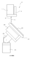
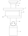
- the coating device includes a second stage 121 provided on the stage 21 as shown in FIGS. 15 and 16.
- the second stage 121 is configured to have a smaller area than the stage 21 and is suitable for performing a coating operation on a small-sized work.
- the second stage 121 is coupled to the stage 21 via a coupling member 122.
- the connecting member 122 is provided with a connecting mechanism for detachably connecting the second stage 121, and it is possible to replace the second stage 121 with the third and subsequent stages different in area from the second stage 121.
- the coating apparatus according to the third embodiment can connect one selected stage to the connecting member 122 among a plurality of stages having different areas.
- the second stage 121 and the third and subsequent stages also include a fixing mechanism that fixes the workpiece 20.
- the lower end portion of the connecting member 122 is detachably connected to the stage 21.
- the stage 20 can hold the work 20 and perform the coating operation.
- the other configuration of the coating apparatus according to the third embodiment is the same as that of the coating apparatus 100 according to the first embodiment, and thus the description thereof will be omitted.
- the discharge apparatus 1 can hold the work 20 by holding the work 20 on the stage smaller in area than the work 20. Interference with the stage 21 can be prevented.
- the coating apparatus of the third embodiment can also be used for adhesion of a case (main body) of a smartphone, and coating work such as 3DMID (3D Molded Interconnected Device), and the same function and effect as the first embodiment can be exhibited. .
- Ejection device 2 Nozzle 3: Liquid storage container 4: Ejection head 5: Droplet 6: Application area 10: Base plate 11: Imaging device 12: Distance measuring device 13: Ejection unit 14: Ejection drive device 15: Ejection port 16: Plunger 20: application object (work) 21: Stage 22: R-axis rotating device 23: P-axis rotating device 24: Utility unit 25: Support table 100: (in the first embodiment) Coating device 101: Mounting frame 102: Top plate 103: Opening 104: Support plate 105: X direction drive device (X direction movement device) 106: Y direction drive device (Y direction moving device) 107: Z direction drive device (Z direction moving device) 108: X movement direction 109: Y movement direction 110: Z movement direction 111: stage movement space 112: control device 113: input / output device 114: dispense controller (discharge control device) 121: second stage 122: support member 200: coating device 201 (of the second embodiment): frame 202: post 205: X-dire
Abstract
課題:吐出ヘッドに回転機構を設けることなく、三次元的な塗布描画を行うことを可能とする塗布装置および塗布方法の提供。 解決手段:Z方向に開口する吐出口を有する吐出装置を備えた吐出ヘッドと、ワークを保持するステージと、前記吐出ヘッドと前記ステージとを相対移動させるXYZ相対移動装置と、XY平面と平行なR軸を中心にステージを回動させるR軸回転装置と、XY平面と平行かつR軸と異なる方向のP軸を中心にステージを回動させるP軸回転装置と、制御装置と、架台と、を備え、前記P軸回転装置が、前記R軸回転装置の下方に配置されており、前記P軸回転装置が、前記ステージと共に前記R軸回転装置を回転させる塗布装置および同装置を用いた塗布方法。
Description
本発明は、塗布対象物を保持するステージを傾けて塗布を行うことが可能な塗布装置および塗布方法に関する。
ノズルから液体材料を吐出し、ステージに搭載したワーク上に吐出した液体材料を塗布する液体材料塗布装置が知られている。近年は、三次元的な立体物に対し塗布描画するニーズが増えており、特に三次元的な立体物の側面に塗布描画する技術が求められている。
例えば、特許文献1では、ステージを傾けることで、液体材料を吐出するワークの位置決めを簡略化した液体材料塗布装置が開示されている。
例えば、特許文献1では、ステージを傾けることで、液体材料を吐出するワークの位置決めを簡略化した液体材料塗布装置が開示されている。
高速塗布を行うためには、吐出ヘッドを軽量化することが重要であり、このことは三次元的な立体物に対し塗布描画する場合も同様である。三次元的な塗布描画を行うために吐出ヘッドに回転機構を設けると吐出ヘッドの重量が増し、吐出ヘッドを高速に移動することができなくなるという課題がある。
そこで、本発明では、吐出ヘッドに回転機構を設けることなく、三次元的な塗布描画を行うことを可能とする塗布装置および塗布方法を提供することを目的とする。
本発明の塗布装置は、Z方向に開口する吐出口を有する吐出装置を備えた吐出ヘッドと、ワークを保持するステージと、前記吐出ヘッドと前記ステージとを相対移動させるXYZ相対移動装置と、XY平面と平行なR軸を中心にステージを回動させるR軸回転装置と、XY平面と平行かつR軸と異なる方向のP軸を中心にステージを回動させるP軸回転装置と、制御装置と、架台と、を備え、前記P軸回転装置が、前記R軸回転装置の下方に配置されており、前記P軸回転装置が、前記ステージと共に前記R軸回転装置を回転させることを特徴とする。ここで、吐出ヘッドは吐出装置を回転させるための回転機構を備えていないため、吐出ヘッドを軽量化することが可能である。
上記塗布装置において、前記R軸回転装置により、前記ステージを±60°以上回転させることができ、前記P軸回転装置により、前記ステージを±60°以上回転させることができることを特徴としてもよい。
上記塗布装置において、前記R軸回転装置により、前記ステージを±90°回転させることができ、前記P軸回転装置により、前記ステージを±90°回転させることができることを特徴としてもよい。ここでいう、±90°回転には、±90°を超えて回転させる態様も含まれる。
上記塗布装置において、前記ステージをθ方向に回転させる回転機構を備えていないことを特徴としてもよい。
上記塗布装置において、前記ステージのR軸と直交する方向の最大幅L1が、前記ステージのP軸と直交する方向の最大幅L2よりも短いことを特徴としてもよい。
上記塗布装置において、前記R軸回転装置の動作時に前記ステージの側辺の下方に位置する部材の上端からR回転軸までの高さH1が、前記L1の半分以上の距離となるように構成されており、前記P軸回転装置の動作時に前記ステージの側辺の下方に位置する部材の上端からP回転軸までの高さH2が、前記L2の半分以上の距離となるように構成されていることを特徴としてもよい。
上記塗布装置において、前記架台が、前記ステージの可動範囲を開口した天板および前記ステージをR軸およびP軸を中心に回動可能とするステージ移動空間を備えることを特徴としてもよく、さらに、前記XYZ相対移動装置が、前記天板上に配置されることを特徴としてもよい。
上記塗布装置において、前記XYZ相対移動装置が、前記ステージを挟んで配置された2つの第1方向移動装置、2つの第1方向移動装置を架橋する第2方向移動装置、および、前記第2方向移動装置に取り付けられた第3方向移動装置により構成されていることを特徴としてもよい。
上記塗布装置において、前記架台から上方に延びる複数本の支柱と、前記架台上に設置されたテーブルと、を備え、前記R軸回転装置および前記P軸回転装置が、前記テーブル上に設置されており、前記XYZ相対移動装置が、前記テーブルを第1の方向に移動させる第1方向移動装置、前記複数本の支柱に支持された第2方向移動装置、および、前記第2方向移動装置に取り付けられた第3方向移動装置により構成されていることを特徴としてもよい。
上記塗布装置において、前記吐出ヘッドが、前記第3方向移動装置に搭載されており、前記吐出装置を回転させる回転機構を備えていないことを特徴としてもよい。
上記塗布装置において、前記ステージが、面積の異なる複数のステージからなり、選択された一のステージによりワークを保持して塗布作業を行うことができることを特徴としてもよい。
上記塗布装置において、前記吐出装置が、弁体を進出移動させ、次いで停止することで液体材料に慣性力を印加して飛翔吐出させるジェット式の吐出装置であることを特徴としてもよい。
上記塗布装置において、前記XYZ相対移動装置が、前記吐出ヘッドと前記ステージとをX方向の直線に沿って相対移動させるX方向移動装置と前記吐出ヘッドと前記ステージとをY方向の直線に沿って相対移動させるY方向移動装置、および、前記吐出ヘッドと前記ステージとをZ方向の直線に沿って相対移動させるZ方向移動装置から構成されており、前記制御装置が、直線状または曲線状の塗布線を形成する際には、前記X方向移動装置および前記Y方向移動装置の少なくとも一方を動作させ、前記吐出ヘッドが常に相対移動動作を継続させることを特徴としてもよい。
本発明の第1の観点の塗布方法は、上記塗布装置を用いてステージ上のワークに塗布する塗布方法である。
本発明の第2の観点の塗布方法は、上記塗布装置を用いてステージ上のワークに塗布する塗布方法であって、前記R軸回転装置により前記ステージを回転させ、前記R軸回転装置および前記P軸回転装置を停止して前記吐出装置と前記ワークとのクリアランスを一定に保ったまま前記ワークの第1の側面を塗布する第1側面塗布工程、前記P軸回転装置により前記ステージを回転させ、前記R軸回転装置および前記P軸回転装置を停止して前記吐出装置と前記ワークとのクリアランスを一定に保ったまま前記ワークの第1の側面と交わる第2の側面を塗布する第2側面塗布工程、を備え、前記第1側面塗布工程の実施後、前記第2側面塗布工程を、或いは、前記第2側面塗布工程の実施後、前記第1側面塗布工程を実施することを特徴とする。
上記第2の観点の塗布方法において、前記第1側面塗布工程の実施後、前記第2側面塗布工程の実施前に、或いは、前記第2側面塗布工程の実施後、前記第1側面塗布工程の実施前に実施されるコーナー部塗布工程を備え、前記コーナー部塗布工程において、前記R軸回転装置および前記P軸回転装置を動作させながら、前記ワークの第1側面および第2側面と連続するアールを有するコーナー部を前記吐出装置と前記ワークとのクリアランスを一定に保ったまま塗布することを特徴としてもよい。
上記第1および第2の観点の塗布方法において、前記ワークが、前記ステージを覆う大きさであることを特徴としてもよい。
本発明によれば、吐出ヘッドに回転機構を設けることなく、三次元的な塗布描画を行うことを可能とする塗布装置および塗布方法を提供することが可能となる。
以下に、本発明を実施するための形態例を説明する。
<第1実施形態>
第1実施形態に係る塗布装置100は、図1に示すように、液体材料を吐出するための吐出装置1、塗布対象物(ワーク)20をその上面に載置するステージ21、ステージ21をR軸回転させるR軸回転装置22、ステージ21をP軸回転させるP軸回転装置23、吐出装置1とステージ21とを相対移動させるXYZ相対移動装置(105、106、107)、各装置の動作を制御する制御装置112、から主に構成される。
<第1実施形態>
第1実施形態に係る塗布装置100は、図1に示すように、液体材料を吐出するための吐出装置1、塗布対象物(ワーク)20をその上面に載置するステージ21、ステージ21をR軸回転させるR軸回転装置22、ステージ21をP軸回転させるP軸回転装置23、吐出装置1とステージ21とを相対移動させるXYZ相対移動装置(105、106、107)、各装置の動作を制御する制御装置112、から主に構成される。
ステージ21は、上面に塗布対象物20を載置する平面を有する平板状の部材であり、塗布対象物(ワーク)20をステージ21に固定する固定機構を備えている。この固定機構としては、例えば、ステージ21内部から上面へ通じる複数の孔を開け、その孔から空気を吸い込むことで塗布対象物20を吸着固定する機構、塗布対象物20を固定用部材で挟み込み、その部材をネジ等の固定手段でステージ21に固定することで塗布対象物20を固定する機構などを用いることができる。ステージ21は、X方向に長さL1の短辺を有し(図5参照)、Y方向に長さL2の長辺を有している(図6参照)。ステージ21に搭載するワークの面積は、ステージ21の面積よりも大きいことが好ましく、上面から視た際にステージ21の全面を覆う大きさであることがより好ましい。ステージ21をワークよりも小さく構成することにより、ステージ21を傾けてワークの側面に塗布する際に、吐出装置1がステージ21に干渉することを回避することが可能となる。なお、ステージ21の形状は長方形に限られず、正方形、多角形、円形などの形状であってもよい。
XYZ相対移動装置は、架台101上に配置されたX方向駆動装置105、Y方向駆動装置106、Z方向駆動装置107から構成される。本実施例では、吐出装置1をステージ21に対してX方向(符号108)、Y方向(符号109)、Z方向(符号110)に、いずれも直線的に相対移動させる構成となっている。換言すれば、XYZ相対移動装置は、X方向の直線移動、Y方向の直線移動、および、Z方向の直線移動の組み合わせにより、吐出装置1のノズル2とステージ21上のワークとを相対移動させるよう構成されている。X方向駆動装置105は、2つのY方向駆動装置106a,106bを架橋するように搭載されており、Z方向駆動装置107は、X方向駆動装置105に搭載されている。XYZ相対移動装置(105、106、107)には、電動モータ(サーボモータ、ステッピングモータなど)とボールネジを組み合わせたものや、リニアモータなどを用いることができる。
なお、Z方向駆動装置107を、R軸回転装置22およびP軸回転装置23と支持板104の間に設けるようにしてもよい。
なお、Z方向駆動装置107を、R軸回転装置22およびP軸回転装置23と支持板104の間に設けるようにしてもよい。
制御装置112は、図示しない処理装置と、記憶装置とを備えており、吐出装置1、R軸回転装置22、P軸回転装置23およびXYZ相対移動装置(105、106、107)が接続されて、これら各装置の動作を制御する。処理装置、記憶装置として、例えば、パーソナルコンピュータ(PC)、プログラマブルロジックコントローラ(PLC)などを用いることができる。制御装置112と双方向通信が可能な入出力装置113としては、図示のタッチパネルの他、キーボードおよびマウスなどを用いることもできる。制御装置112の記憶装置には、本発明の塗布方法を実現するための塗布プログラムが格納されている。
第1実施形態の吐出装置1は、液体材料が吐出口から離間する前にワークに接触するタイプの吐出方式のもの、液体材料が吐出口から離間した後にワークに接触するタイプの吐出方式のものを採用することができる。
液体材料が吐出口から離間する前にワークに接触するタイプの吐出方式としては、先端にノズルを有するシリンジ内の液体材料に調圧されたエアを所望時間だけ印加するエア式、フラットチュービング機構またはロータリチュービング機構を有するチュービング式、先端にノズルを有する貯留容器の内面に密着摺動するプランジャーを所望量移動して吐出するプランジャー式、スクリューの回転により液体材料を吐出するスクリュー式、所望圧力が印加された液体材料をバルブの開閉により吐出制御するバルブ式などが例示される。
液体材料が吐出口から離間する前にワークに接触するタイプの吐出方式としては、先端にノズルを有するシリンジ内の液体材料に調圧されたエアを所望時間だけ印加するエア式、フラットチュービング機構またはロータリチュービング機構を有するチュービング式、先端にノズルを有する貯留容器の内面に密着摺動するプランジャーを所望量移動して吐出するプランジャー式、スクリューの回転により液体材料を吐出するスクリュー式、所望圧力が印加された液体材料をバルブの開閉により吐出制御するバルブ式などが例示される。
液体材料が吐出口から離間した後にワークに接触するタイプの吐出方式としては、プランジャー(弁体)を進出移動させ、急激に停止して、液体材料に慣性力を印加してノズルの先端より飛翔吐出させるジェット式、連続噴射方式或いはデマンド方式のインクジェットタイプなどが例示される。
吐出装置1は、撮像装置11および距離測定装置12と共にベース板10に取り付けられている。すなわち、XYZ相対移動装置により吐出装置1を塗布対象物20に対し相対移動させると、撮像装置11および距離測定装置12も吐出装置1と一体的に相対移動する。ベース板10に取り付けられた各装置(1,11~12)が吐出ヘッド4を構成する。吐出ヘッド4には、各装置(1,11~12)を回転させる回転機構を設けられていないため、回転機構を設けた吐出ヘッドと比べ軽量である。
図13は、第1実施形態に係る塗布装置100に搭載することのできる、ジェット式の吐出装置1の要部断面側面図である。吐出装置1は、ノズル2と、液体貯留容器3と、吐出部13と、吐出駆動装置14とを備えている。
吐出装置1は、ノズル2の吐出口15に連通する吐出部13の液室内に、液室の側壁と非接触または一部接触するが液材の流動を妨げない、プランジャー16が設けられている。そして、このプランジャー16を高速で進退させることで、液材に慣性力を与え、ノズル2の吐出口15から液滴の状態で液体材料を飛滴吐出させることができる。
ノズル2の吐出口15は、Z方向(鉛直方向)に開口している。換言すれば、ノズル2の吐出口15は、XY平面と平行な端面を有している(図13参照)。ノズル2は、その中心線がZ方向(鉛直方向)に伸びる真っ直ぐな管により構成することが好ましい。
吐出装置1は、ノズル2の吐出口15に連通する吐出部13の液室内に、液室の側壁と非接触または一部接触するが液材の流動を妨げない、プランジャー16が設けられている。そして、このプランジャー16を高速で進退させることで、液材に慣性力を与え、ノズル2の吐出口15から液滴の状態で液体材料を飛滴吐出させることができる。
ノズル2の吐出口15は、Z方向(鉛直方向)に開口している。換言すれば、ノズル2の吐出口15は、XY平面と平行な端面を有している(図13参照)。ノズル2は、その中心線がZ方向(鉛直方向)に伸びる真っ直ぐな管により構成することが好ましい。
ジェット式の吐出装置1によれば、ノズル2の吐出口15とワークとの間に距離を設けて塗布作業が行われる(液滴を飛翔吐出させる)ため、R軸およびP軸の回転動作により生じる吐出口15とワーク間の距離のズレに対する許容性がある。また、ノズル2とワークの間に距離を設けて塗布作業が行われるため、ノズル2を上昇させなくとも、R軸およびP軸の回転動作を行うことができる。他の吐出方式の吐出装置では点塗布時にXYZ相対移動装置の動作を停止させるのに対し、ジェット式の吐出装置1はX方向駆動装置105およびY方向駆動装置106のいずれか一方を動作させながら連続点的に塗布を行うので、生産性に優れている。
撮像装置11は、CCDカメラ等のデジタルカメラである。撮像装置11により撮像した塗布対象物20の画像を見ながら、塗布位置を指定するティーチング作業を行うことが可能である。
距離測定装置12は、レーザー光をワークに照射してワーク表面までの距離を計測するレーザー変位センサー等の非接触式計測装置である。これとは異なり、ワーク表面に接触してワーク表面までの距離を計測する接触式計測装置を採用してもよい。
距離測定装置12は、レーザー光をワークに照射してワーク表面までの距離を計測するレーザー変位センサー等の非接触式計測装置である。これとは異なり、ワーク表面に接触してワーク表面までの距離を計測する接触式計測装置を採用してもよい。
架台101は、開口103が形成された天板102を備えている。開口103は、ステージ21の可動範囲を確保した大きさとなっており、開口103内にステージ21、R軸回転装置22、P軸回転装置23およびユーティリティユニット24が配置されている。天板102の開口103の下方にはステージ21のR軸およびP軸を回転中心とする回転動作を可能とするためのステージ移動空間111が設けられている。なお、ステージ移動空間111が確保できるのであれば、天板102を設けずに、Y相対移動装置106を支持する支持部材を設けるようにしてもよい。また、架台101の天板102より上の部分を覆う扉付きカバーを設けるようにしてもよい。
R軸回転装置22は、Y移動方向109と平行なR軸を中心にステージ21を回動することを可能とする装置である。別の言い方をすれば、R軸回転装置22は、R軸を中心にステージ21を左右(第1の方向)に傾けることを可能としている。図2に示すように、R軸回転装置22は、R軸を中心に回転するR軸回転体22aと、電動モータ等により構成されるR軸回動装置(R軸駆動源)22bと、ベース板22cを備えて構成されている。
P軸回転装置23は、R軸と直交するP軸を中心にステージ21を回動することを可能とする装置である。別の言い方をすれば、P軸回転装置23は、P軸を中心にステージ21を前後(第1の方向と直交する第2の方向)に傾けることを可能としている。P軸回転装置23は、P軸を中心に回転するP軸回転体23aと、電動モータ等により構成されるP軸回動装置(P軸駆動源)23bを備えて構成されており、支持台25に固定されている。第1実施形態においては、R軸をY方向と一致させているが、R軸をY方向と一致させなくともよい。また、R軸とP軸を第1実施形態のように直交させなくともよく、例えばR軸とP軸が30°、45°または60°の角を構成するような位置関係となる場合もある。
P軸回転装置23は、R軸と直交するP軸を中心にステージ21を回動することを可能とする装置である。別の言い方をすれば、P軸回転装置23は、P軸を中心にステージ21を前後(第1の方向と直交する第2の方向)に傾けることを可能としている。P軸回転装置23は、P軸を中心に回転するP軸回転体23aと、電動モータ等により構成されるP軸回動装置(P軸駆動源)23bを備えて構成されており、支持台25に固定されている。第1実施形態においては、R軸をY方向と一致させているが、R軸をY方向と一致させなくともよい。また、R軸とP軸を第1実施形態のように直交させなくともよく、例えばR軸とP軸が30°、45°または60°の角を構成するような位置関係となる場合もある。
図3および図4に示すように、R軸回転装置22は、天板102と実質的に同じ高さに配置されており、天板102の開口103の下方にはステージ移動空間111が設けられているので、R軸回転装置22を駆動させた際にステージ21の側辺21a,21bがベース板22cの付近に到達するまで回動させることができる(図5参照)。換言すれば、R軸回転装置22を駆動させた際に、水平位置にあるステージ21をR軸を中心に±60°以上(好ましくは±75°以上、より好ましくは±90°)回転させることができる。ここで、R軸を中心に±90°の回転を実現するためには、R軸回転時にステージ21の側辺の下方に位置するP軸回転装置23(すなわち、P軸回動装置(P軸駆動源)23b)の上端からR回転軸22dまでの高さH1が、ステージ21の短辺の長さL1の半分以上の距離となるように構成することが必要である(図5参照)。なお、ステージ21が矩形でない場合、長さL1はステージ21のP軸方向(R軸と直交する方向)の最大幅となる。
第1実施形態では、R軸回転装置22を天板102に埋設する高さに設置することにより、Y方向移動装置106a,106bの高さを低くすることができる。これにより、ノズル2とステージ21との距離を短くし、液滴の着弾位置の精度を高めることを可能としている。
第1実施形態では、R軸回転装置22を天板102に埋設する高さに設置することにより、Y方向移動装置106a,106bの高さを低くすることができる。これにより、ノズル2とステージ21との距離を短くし、液滴の着弾位置の精度を高めることを可能としている。
R軸回転装置22およびP軸回転装置23は、架台101内の支持板104上に配置された支持台25により支持されている。支持板104上にはステージ移動空間111が設けられているので、P軸回転装置23を駆動させた際にステージ21の側辺21c,21dが支持台25の付近に到達するまで回動させることができる(図6参照)。換言すれば、P軸回転装置23を駆動させた際に、水平位置にあるステージ21(またはR軸回転装置22)をP軸を中心に±60°以上(好ましくは±75°以上、より好ましくは±90°)回転させることができる。ここで、P軸を中心に±90°の回転を実現するためには、P軸回転時にステージ21の側辺の下方に位置する部材(すなわち、支持板104)の上端からP回転軸23dまでの高さH2が、ステージ21の長辺の長さL2の半分以上の距離となるように構成することが必要である(図6参照)。なお、ステージ21が矩形でない場合、長さL2はステージ21のR軸方向(P軸と直交する方向)の最大幅となる。
図7に示すように、支持板104上には、ユーティリティユニット24が設置されている。ユーティリティユニット24は、ノズルクリーニング機構、捨て打ちステージ、クリアランス調整機構等を備えている。図1を見ると分かるように、ユーティリティユニット24とステージ21とは、P軸回転装置23によりステージ21を回転させるために必要なクリアランスが設けられている。
図7に示すように、支持板104上には、ユーティリティユニット24が設置されている。ユーティリティユニット24は、ノズルクリーニング機構、捨て打ちステージ、クリアランス調整機構等を備えている。図1を見ると分かるように、ユーティリティユニット24とステージ21とは、P軸回転装置23によりステージ21を回転させるために必要なクリアランスが設けられている。
図8は、R軸回転装置22によりステージ21を傾けた状態で塗布を行っている様子を説明するための側面図である。R軸回転装置22によりステージ21を傾けることにより、塗布対象物20の第1の側面に液体材料を塗布することが可能となる。
図9は、P軸回転装置23によりステージ21を傾けた状態で塗布を行っている様子を説明するための側面図である。P軸回転装置23によりステージ21を傾けることにより、塗布対象物20の第1の側面と直交する第2の側面に液体材料を塗布することが可能となる。
第1実施形態の塗布装置100は、制御装置112がXYZ相対移動装置(105、106、107)の座標変換を行う機能を備えているので、ステージ21をθ軸回転させるθ軸回転装置が不要である。XY平面がθ回転面となるから、座標変換作業でθ補正を行うことができるからである。もっとも、ステージ21をθ軸回転させるθ軸回転装置を設けても、本発明の塗布方法を実施することは可能である。
図10は、スマートフォンのカバーであるワーク20において塗布作業を行う箇所を説明するための図である。同図を見ると分かるように、ワーク20はステージ21を覆う大きさである。スマートフォンのカバーにおいて塗布作業を行う際には、(a)から順に(b)、(c)、(d)、(e)、(f)、(g)、(h)と描画し、(a)に戻って、塗布描画が終了する。(a)~(h)の各点を通過する一本の切れ目のない線を塗布描画する方法としては、ノズルから吐出された液体材料が分断されないように連続的に吐出して塗布描画する方法と、点を重ねて線を形成する方法があるが、いずれの方法も本発明に適用可能である。
図11は、図10のスマートフォンのカバーの側面である塗布領域6を説明するための拡大図である。このカバーの塗布領域6は、外側下向きに傾斜している線状の面(面取りされているかのような面)である。
図12は、スマートフォンのカバーにおいて塗布作業を行う手順を説明するための図である。図12の(a)~(h)は、図10の(a)~(h)に対応している。なお、図12においては、説明の便宜上、ノズル2を通常よりも大きく描画している。以下の(a)~(h)における上下左右方向は、図10における上下左右方向の意味である。
図12は、スマートフォンのカバーにおいて塗布作業を行う手順を説明するための図である。図12の(a)~(h)は、図10の(a)~(h)に対応している。なお、図12においては、説明の便宜上、ノズル2を通常よりも大きく描画している。以下の(a)~(h)における上下左右方向は、図10における上下左右方向の意味である。
(a)塗布開始時(ワーク左側側面の下方)
R軸回転装置22によりステージ21を右方向に回転させ、ワーク20の塗布領域6をノズル2に対向させる。ワーク左側の下方に設定された塗布開始位置から吐出装置1に吐出を開始させ、XYZ相対移動装置(105、106、107)によりノズル2とワーク20とを相対移動させ(この場合はY方向(図10の上方向))、ワーク左側側面(第1の側面)である塗布領域6に液体材料を塗布する。この際、R軸回転装置22およびP軸回転装置23は、いずれも停止しており、ノズル2の先端の吐出口とワーク20とのクリアランスは一定に保たれる。
R軸回転装置22によりステージ21を右方向に回転させ、ワーク20の塗布領域6をノズル2に対向させる。ワーク左側の下方に設定された塗布開始位置から吐出装置1に吐出を開始させ、XYZ相対移動装置(105、106、107)によりノズル2とワーク20とを相対移動させ(この場合はY方向(図10の上方向))、ワーク左側側面(第1の側面)である塗布領域6に液体材料を塗布する。この際、R軸回転装置22およびP軸回転装置23は、いずれも停止しており、ノズル2の先端の吐出口とワーク20とのクリアランスは一定に保たれる。
(b)ワーク左側上方コーナー部(第1のコーナー部)
ワーク左側上方コーナー部は、第1の側面および第2の側面と連続するアールを有するコーナー部である。R軸回転装置22によりステージを左に回転させつつP軸回転装置23によりステージを手前側に回転させる。このR軸回転装置22およびP軸回転装置23によるステージ21の回転と、ノズル2の位置を制御するXYZ相対移動装置の動作を制御装置112が同期させることにより、ワーク20のコーナー部を塗布描画することができる。図11に示すように、ワーク20のコーナー部も外側に向かって傾斜しているので、この塗布面が常にノズル側に向かうようR軸回転装置22およびP軸回転装置23によりステージ21を同時に二方向に回転させる。この際も上記(a)と同様、ノズル2の先端の吐出口とワーク20とのクリアランスは一定に保たれる。
コーナー部の描画速度を上記(a)の直線部の描画速度と異なる速度で描画することも可能である。ステージ21の回転速度、XYZ相対移動装置によるノズル2の移動速度および吐出装置1の吐出動作(吐出量)をコントロールすることで、例えば、直線部と比べコーナー部を低速で描画することができる。ここで、コーナー部において低速で描画する際には、単位時間あたりの吐出量を減少させる。
(c)ワーク上側の直線部(第2の側面)
上記(a)と同様に、XYZ相対移動装置によりノズル2を移動させ(この場合はX方向)、ワーク上側の塗布領域6を塗布描画する。この際、R軸回転装置22およびP軸回転装置23は、いずれも停止している。
上記(a)と同様に、XYZ相対移動装置によりノズル2を移動させ(この場合はX方向)、ワーク上側の塗布領域6を塗布描画する。この際、R軸回転装置22およびP軸回転装置23は、いずれも停止している。
(d)ワーク右側上方コーナー部(第2のコーナー部)
ワーク右側上方コーナー部は、第2の側面および第3の側面と連続するアールを有するコーナー部である。P軸回転装置23によりステージ21を奥側へ回転させつつ、R軸回転装置22によりステージを左側へ回転させる。この際、上記(b)と同様、R軸回転装置22およびP軸回転装置23によるステージ21の回転と、ノズル2の位置を制御するXYZ相対移動装置の動作を制御装置112が同期させる。
ワーク右側上方コーナー部は、第2の側面および第3の側面と連続するアールを有するコーナー部である。P軸回転装置23によりステージ21を奥側へ回転させつつ、R軸回転装置22によりステージを左側へ回転させる。この際、上記(b)と同様、R軸回転装置22およびP軸回転装置23によるステージ21の回転と、ノズル2の位置を制御するXYZ相対移動装置の動作を制御装置112が同期させる。
(e)ワーク右側の直線部(第3の側面)
上記(a)と同様、XYZ相対移動装置によりノズル2を移動させ(この場合はY方向)、ワーク右側の塗布領域6を塗布描画する。この際、R軸回転装置22およびP軸回転装置23は、いずれも停止している。
上記(a)と同様、XYZ相対移動装置によりノズル2を移動させ(この場合はY方向)、ワーク右側の塗布領域6を塗布描画する。この際、R軸回転装置22およびP軸回転装置23は、いずれも停止している。
(f)ワーク右側下方コーナー部(第3のコーナー部)
ワーク右側下方コーナー部は、第3の側面および第4の側面と連続するアールを有するコーナー部である。P軸回転装置23によりステージ21を奥側へ回転させつつ、R軸回転装置22によりステージ21を右側へ回転させる。この際、上記(b)と同様、R軸回転装置22およびP軸回転装置23によるステージ21の回転と、ノズル2の位置を制御するXYZ相対移動装置の動作を制御装置112が同期させる。
ワーク右側下方コーナー部は、第3の側面および第4の側面と連続するアールを有するコーナー部である。P軸回転装置23によりステージ21を奥側へ回転させつつ、R軸回転装置22によりステージ21を右側へ回転させる。この際、上記(b)と同様、R軸回転装置22およびP軸回転装置23によるステージ21の回転と、ノズル2の位置を制御するXYZ相対移動装置の動作を制御装置112が同期させる。
(g)ワーク下側の直線部(第4の側面)
上記(a)と同様、XYZ相対移動装置によりノズル2を移動させ(この場合はX方向)、ワーク下側の塗布領域6を塗布描画する。この際、R軸回転装置22およびP軸回転装置23は、いずれも停止している。
上記(a)と同様、XYZ相対移動装置によりノズル2を移動させ(この場合はX方向)、ワーク下側の塗布領域6を塗布描画する。この際、R軸回転装置22およびP軸回転装置23は、いずれも停止している。
(h)ワーク左側下方コーナー部(第4のコーナー部)
ワーク左側下方コーナー部は、第4の側面および第1の側面と連続するアールを有するコーナー部である。P軸回転装置23によりステージ21を手前側へ回転させつつ、R軸回転装置22によりステージ21を右側へ回転させる。この際、上記(b)と同様、R軸回転装置22およびP軸回転装置23によるステージ21の回転と、ノズル2の位置を制御するXYZ相対移動装置の動作を制御装置112が同期させる。
ワーク左側下方コーナー部を描画し終わると、R軸回転装置22およびP軸回転装置23は、上記(a)と同じ位置となる。塗布開始位置まで描画したら一のワーク20に対する塗布作業は終了である。
ワーク左側下方コーナー部は、第4の側面および第1の側面と連続するアールを有するコーナー部である。P軸回転装置23によりステージ21を手前側へ回転させつつ、R軸回転装置22によりステージ21を右側へ回転させる。この際、上記(b)と同様、R軸回転装置22およびP軸回転装置23によるステージ21の回転と、ノズル2の位置を制御するXYZ相対移動装置の動作を制御装置112が同期させる。
ワーク左側下方コーナー部を描画し終わると、R軸回転装置22およびP軸回転装置23は、上記(a)と同じ位置となる。塗布開始位置まで描画したら一のワーク20に対する塗布作業は終了である。
以上に説明した第1実施形態の塗布装置100は、スマートフォンのケース(本体)の接着や、3DMID(3D Molded Interconnected Device)などの塗布作業に利用することができる。また、二つの板状体を貼り合わせた際の辺縁(端面)に保護材を塗布することにも利用される。本装置ではこの様な周面を塗布するにあたっても、その周面がノズルの吐出口方面へ向かうようステージを回転させることができるため、ワークを立てた状態で塗布するための治具等が不要である。また、ワークのステージに面する以外の部分は全て塗布対象となることから、ワークの側周面についてもワークの体勢を変えることなく塗布することが可能となる。
<第2実施形態>
第2実施形態に係る塗布装置200は、図14に示すように、液体材料を吐出するための吐出装置1、塗布対象物をその上面に載置するステージ21、ステージ21をR軸回転させるR軸回転装置22、ステージ21をP軸回転させるP軸回転装置23、吐出装置1とステージ21とを相対移動させるXYZ相対移動装置(205、206、207)、各装置の動作を制御する制御装置112、から主に構成される。第2実施形態において、第1実施形態と同様の構成については同じ符号を付し、説明を省略する場合がある。
第2実施形態に係る塗布装置200は、図14に示すように、液体材料を吐出するための吐出装置1、塗布対象物をその上面に載置するステージ21、ステージ21をR軸回転させるR軸回転装置22、ステージ21をP軸回転させるP軸回転装置23、吐出装置1とステージ21とを相対移動させるXYZ相対移動装置(205、206、207)、各装置の動作を制御する制御装置112、から主に構成される。第2実施形態において、第1実施形態と同様の構成については同じ符号を付し、説明を省略する場合がある。
吐出装置1は、Z方向駆動装置207に搭載されており、Z方向駆動装置207はX方向駆動装置205に搭載されている。吐出装置1の下方に位置するステージ21は、Y方向駆動装置206に搭載されている。これにより、吐出装置1とステージ21とをXYZ方向(108、109、110)に相対移動させることができる。第2実施形態では、Z方向駆動装置207に撮像装置11および距離測定装置12を搭載していないが、これらを搭載するようにしてもよい。
X方向駆動装置205は、架台201から上方に延びる2本の支柱202a,202bにより支持されており、架台201上面の2本の支柱202a,202bの間にはY方向駆動装置206が配置されている。Y方向駆動装置206にはテーブル221が搭載されており、テーブル221には第1実施形態と同様のステージ21、R軸回転装置22およびP軸回転装置23が支持台25を介して設置されている。
第2実施形態に係る塗布装置200においても、R軸回転装置22を駆動させることにより、水平位置にあるステージ21をR軸を中心に±60°以上(好ましくは±75°以上、より好ましくは±90°)回転させることができる。また、P軸回転装置23を駆動させることにより、水平位置にあるステージ21(またはR軸回転装置22)をP軸を中心に±60°以上(好ましくは±75°以上、より好ましくは±90°)回転させることができる。
第2実施形態に係る塗布装置200においても、R軸回転装置22を駆動させることにより、水平位置にあるステージ21をR軸を中心に±60°以上(好ましくは±75°以上、より好ましくは±90°)回転させることができる。また、P軸回転装置23を駆動させることにより、水平位置にあるステージ21(またはR軸回転装置22)をP軸を中心に±60°以上(好ましくは±75°以上、より好ましくは±90°)回転させることができる。
XYZ相対移動装置(205、206、207)等の動作を制御する制御装置112は、架台201の内部に配置されている。吐出装置1の吐出動作を制御するディスペンスコントローラ(吐出制御装置)114は、架台201の外部に配置されており、信号ケーブルを介して制御装置112および吐出装置1と電気的に接続されている。
以上に説明した第2実施形態の塗布装置200も、スマートフォンのケース(本体)の接着や、3DMID(3D Molded Interconnected Device)などの塗布作業に利用することができ、第1実施形態と同様の作用効果が奏される。
以上に説明した第2実施形態の塗布装置200も、スマートフォンのケース(本体)の接着や、3DMID(3D Molded Interconnected Device)などの塗布作業に利用することができ、第1実施形態と同様の作用効果が奏される。
<第3実施形態>
第3実施形態に係る塗布装置は、図15および図16に示すように、ステージ21上に設けられた第2のステージ121を備えている。第2のステージ121は、ステージ21と比べ小面積に構成されており、小型のワークへの塗布作業を行う際に適している。
第2のステージ121は、連結部材122を介してステージ21に連結されている。連結部材122は、第2のステージ121を着脱自在に連結する連結機構を備えており、第2のステージ121を第2のステージ121と異なる面積の第3以降のステージに交換することを可能としている。すなわち、第3実施形態に係る塗布装置は、異なる面積を有する複数のステージの中から、選択された一のステージを連結部材122に連結することが可能である。なお、第2のステージ121および第3以降のステージも、ステージ21と同様、ワーク20を固定する固定機構を備えている。
連結部材122の下端部は、ステージ21と着脱自在に連結されており、連結部材122をステージ21から取り外せば、ステージ21によりワーク20を保持して塗布作業を行うこともできる。
第3実施形態に係る塗布装置のその他の構成は、第1実施形態に係る塗布装置100と同様であるので、説明を省略する。
第3実施形態に係る塗布装置のその他の構成は、第1実施形態に係る塗布装置100と同様であるので、説明を省略する。
以上に説明した第3実施形態に係る塗布装置によれば、ワーク20が多品種である場合でも、ワーク20よりも小面積のステージにワーク20を保持させることにより、塗布作業時に吐出装置1がステージ21に干渉することを防ぐことができる。
第3実施形態の塗布装置も、スマートフォンのケース(本体)の接着や、3DMID(3D Molded Interconnected Device)などの塗布作業に利用することができ、第1実施形態と同様の作用効果が奏される。
第3実施形態の塗布装置も、スマートフォンのケース(本体)の接着や、3DMID(3D Molded Interconnected Device)などの塗布作業に利用することができ、第1実施形態と同様の作用効果が奏される。
1:吐出装置
2:ノズル
3:液体貯留容器
4:吐出ヘッド
5:液滴
6:塗布領域
10:ベース板
11:撮像装置
12:距離測定装置
13:吐出部
14:吐出駆動装置
15:吐出口
16:プランジャー
20:塗布対象物(ワーク)
21:ステージ
22:R軸回転装置
23:P軸回転装置
24:ユーティリティユニット
25:支持台
100:(第1実施形態の)塗布装置
101:架台
102:天板
103:開口
104:支持板
105:X方向駆動装置(X方向移動装置)
106:Y方向駆動装置(Y方向移動装置)
107:Z方向駆動装置(Z方向移動装置)
108:X移動方向
109:Y移動方向
110:Z移動方向
111:ステージ移動空間
112:制御装置
113:入出力装置
114:ディスペンスコントローラ(吐出制御装置)
121:第2のステージ
122:支持部材
200:(第2実施形態の)塗布装置
201:架台
202:支柱
205:X方向駆動装置(X方向移動装置)
206:Y方向駆動装置(Y方向移動装置)
207:Z方向駆動装置(Z方向移動装置)
221:テーブル
Claims (18)
- Z方向に開口する吐出口を有する吐出装置を備えた吐出ヘッドと、
ワークを保持するステージと、
前記吐出ヘッドと前記ステージとを相対移動させるXYZ相対移動装置と、
XY平面と平行なR軸を中心にステージを回動させるR軸回転装置と、
XY平面と平行かつR軸と異なる方向のP軸を中心にステージを回動させるP軸回転装置と、
制御装置と、
架台と、を備え、
前記P軸回転装置が、前記R軸回転装置の下方に配置されており、
前記P軸回転装置が、前記ステージと共に前記R軸回転装置を回転させることを特徴とする塗布装置。 - 前記R軸回転装置により、前記ステージを±60°以上回転させることができ、
前記P軸回転装置により、前記ステージを±60°以上回転させることができることを特徴とする請求項1に記載の塗布装置。 - 前記R軸回転装置により、前記ステージを±90°回転させることができ、
前記P軸回転装置により、前記ステージを±90°回転させることができることを特徴とする請求項2に記載の塗布装置。 - 前記ステージのR軸と直交する方向の最大幅L1が、前記ステージのP軸と直交する方向の最大幅L2よりも短いことを特徴とする請求項2または3に記載の塗布装置。
- 前記R軸回転装置の動作時に前記ステージの側辺の下方に位置する部材の上端からR回転軸までの高さH1が、前記L1の半分以上の距離となるように構成されており、
前記P軸回転装置の動作時に前記ステージの側辺の下方に位置する部材の上端からP回転軸までの高さH2が、前記L2の半分以上の距離となるように構成されていることを特徴とする請求項1ないし4のいずれかに記載の塗布装置。 - 前記ステージをθ方向に回転させる回転機構を備えていないことを特徴とする請求項1ないし5のいずれかに記載の塗布装置。
- 前記架台が、前記ステージの可動範囲を開口した天板および前記ステージをR軸およびP軸を中心に回動可能とするステージ移動空間を備えることを特徴とする請求項1ないし6のいずれかに記載の塗布装置。
- 前記XYZ相対移動装置が、前記天板上に配置されることを特徴とする請求項7に記載の塗布装置。
- 前記XYZ相対移動装置が、前記ステージを挟んで配置された2つの第1方向移動装置、2つの第1方向移動装置を架橋する第2方向移動装置、および、前記第2方向移動装置に取り付けられた第3方向移動装置により構成されていることを特徴とする請求項1ないし8のいずれかに記載の塗布装置。
- 前記架台から上方に延びる複数本の支柱と、
前記架台上に設置されたテーブルと、を備え、
前記R軸回転装置および前記P軸回転装置が、前記テーブル上に設置されており、
前記XYZ相対移動装置が、前記テーブルを第1の方向に移動させる第1方向移動装置、前記複数本の支柱に支持された第2方向移動装置、および、前記第2方向移動装置に取り付けられた第3方向移動装置により構成されていることを特徴とする請求項1ないし7のいずれかに記載の塗布装置。 - 前記吐出ヘッドが、前記第3方向移動装置に搭載されており、前記吐出装置を回転させる回転機構を備えていないことを特徴とする請求項9または10に記載の塗布装置。
- 前記ステージが、面積の異なる複数のステージからなり、選択された一のステージによりワークを保持して塗布作業を行うことができることを特徴とする請求項1ないし11のいずれかに記載の塗布装置。
- 前記吐出装置が、弁体を進出移動させ、次いで停止することで液体材料に慣性力を印加して飛翔吐出させるジェット式の吐出装置であることを特徴とする請求項1ないし12のいずれかに記載の塗布装置。
- 前記XYZ相対移動装置が、前記吐出ヘッドと前記ステージとをX方向の直線に沿って相対移動させるX方向移動装置と前記吐出ヘッドと前記ステージとをY方向の直線に沿って相対移動させるY方向移動装置、および、前記吐出ヘッドと前記ステージとをZ方向の直線に沿って相対移動させるZ方向移動装置から構成されており、
前記制御装置が、直線状または曲線状の塗布線を形成する際には、前記X方向移動装置および前記Y方向移動装置の少なくとも一方を動作させ、前記吐出ヘッドが常に相対移動動作を継続させることを特徴とする請求項1ないし13のいずれかに記載の塗布装置。 - 請求項1ないし14のいずれかに記載の塗布装置を用いてステージ上のワークに塗布する塗布方法。
- 請求項1ないし14のいずれかに記載の塗布装置を用いてステージ上のワークに塗布する塗布方法であって、
前記R軸回転装置により前記ステージを回転させ、前記R軸回転装置および前記P軸回転装置を停止して前記吐出装置と前記ワークとのクリアランスを一定に保ったまま前記ワークの第1の側面を塗布する第1側面塗布工程、
前記P軸回転装置により前記ステージを回転させ、前記R軸回転装置および前記P軸回転装置を停止して前記吐出装置と前記ワークとのクリアランスを一定に保ったまま前記ワークの第1の側面と交わる第2の側面を塗布する第2側面塗布工程、を備え、
前記第1側面塗布工程の実施後、前記第2側面塗布工程を、或いは、前記第2側面塗布工程の実施後、前記第1側面塗布工程を実施する塗布方法。 - 前記第1側面塗布工程の実施後、前記第2側面塗布工程の実施前に、或いは、前記第2側面塗布工程の実施後、前記第1側面塗布工程の実施前に実施されるコーナー部塗布工程を備え、
前記コーナー部塗布工程において、前記R軸回転装置および前記P軸回転装置を動作させながら、前記ワークの第1側面および第2側面と連続するアールを有するコーナー部を前記吐出装置と前記ワークとのクリアランスを一定に保ったまま塗布することを特徴とする請求項16に記載の塗布方法。 - 前記ワークが、前記ステージを覆う大きさであることを特徴とする請求項15ないし17のいずれかに記載の塗布方法。
Priority Applications (8)
| Application Number | Priority Date | Filing Date | Title |
|---|---|---|---|
| PL18871999.1T PL3705190T3 (pl) | 2017-11-02 | 2018-11-01 | Urządzenie do nanoszenia ciekłego materiału i sposób nanoszenia |
| JP2019550491A JP7098169B2 (ja) | 2017-11-02 | 2018-11-01 | 液体材料塗布装置および塗布方法 |
| SG11202003074QA SG11202003074QA (en) | 2017-11-02 | 2018-11-01 | Liquid material application device and application method |
| KR1020207010501A KR102562701B1 (ko) | 2017-11-02 | 2018-11-01 | 액체 재료 도포 장치 및 도포 방법 |
| EP18871999.1A EP3705190B1 (en) | 2017-11-02 | 2018-11-01 | Liquid material application device and application method |
| US16/652,824 US11001085B2 (en) | 2017-11-02 | 2018-11-01 | Liquid material application device and application method |
| CN201880071237.5A CN111315496B (zh) | 2017-11-02 | 2018-11-01 | 液体材料涂布装置及涂布方法 |
| PH12020550516A PH12020550516A1 (en) | 2017-11-02 | 2020-04-29 | Liquid material application device and application method |
Applications Claiming Priority (2)
| Application Number | Priority Date | Filing Date | Title |
|---|---|---|---|
| JP2017212998 | 2017-11-02 | ||
| JP2017-212998 | 2017-11-02 |
Publications (1)
| Publication Number | Publication Date |
|---|---|
| WO2019088237A1 true WO2019088237A1 (ja) | 2019-05-09 |
Family
ID=66333522
Family Applications (1)
| Application Number | Title | Priority Date | Filing Date |
|---|---|---|---|
| PCT/JP2018/040765 WO2019088237A1 (ja) | 2017-11-02 | 2018-11-01 | 液体材料塗布装置および塗布方法 |
Country Status (11)
| Country | Link |
|---|---|
| US (1) | US11001085B2 (ja) |
| EP (1) | EP3705190B1 (ja) |
| JP (1) | JP7098169B2 (ja) |
| KR (1) | KR102562701B1 (ja) |
| CN (1) | CN111315496B (ja) |
| HU (1) | HUE063856T2 (ja) |
| PH (1) | PH12020550516A1 (ja) |
| PL (1) | PL3705190T3 (ja) |
| SG (1) | SG11202003074QA (ja) |
| TW (1) | TWI780254B (ja) |
| WO (1) | WO2019088237A1 (ja) |
Cited By (6)
| Publication number | Priority date | Publication date | Assignee | Title |
|---|---|---|---|---|
| CN112547421A (zh) * | 2020-11-30 | 2021-03-26 | 九江市海纳电讯技术有限公司 | 一种合路器加工用的气动点胶仪 |
| CN112547444A (zh) * | 2020-12-22 | 2021-03-26 | 湖州浩通电子科技有限公司 | 一种点膏机的输送装置 |
| JP7365850B2 (ja) | 2019-10-18 | 2023-10-20 | セーレン株式会社 | インクジェット記録装置及びインクジェット記録方法 |
| JP7420458B2 (ja) | 2020-03-30 | 2024-01-23 | トリニティ工業株式会社 | 塗料カートリッジの個体識別システム |
| JP7444679B2 (ja) | 2020-03-30 | 2024-03-06 | トリニティ工業株式会社 | 塗料カートリッジ用ストッカの位置教示システム |
| JP7444678B2 (ja) | 2020-03-30 | 2024-03-06 | トリニティ工業株式会社 | 塗装設備における塗料カートリッジの装着位置補正システム |
Families Citing this family (7)
| Publication number | Priority date | Publication date | Assignee | Title |
|---|---|---|---|---|
| CN111957532B (zh) * | 2020-08-15 | 2021-03-23 | 深圳市恒力天科技有限公司 | 用于点胶机上的工装固定装置 |
| CN114442433A (zh) * | 2020-11-02 | 2022-05-06 | 长鑫存储技术有限公司 | 承载组件及涂胶显影机 |
| KR102540790B1 (ko) * | 2021-05-21 | 2023-06-07 | 에이치비솔루션㈜ | 니들 클리닝 도포 시스템 |
| CN114247606A (zh) * | 2021-12-07 | 2022-03-29 | 深圳市家鸿口腔医疗股份有限公司 | 一种树脂牙与金属桥固位结合用金属结合剂涂抹装置 |
| CN114653535B (zh) * | 2022-03-03 | 2023-05-23 | 台州市邦盈纸品有限公司 | 一种涂布头角度精调机构 |
| CN114361298A (zh) * | 2022-03-21 | 2022-04-15 | 西安宏星电子浆料科技股份有限公司 | 太阳能电池制备系统和制备方法 |
| CN114771109B (zh) * | 2022-04-13 | 2023-05-05 | 浙江欣源电气股份有限公司 | 箱式变电站景观uv喷绘装置及喷绘方法 |
Citations (9)
| Publication number | Priority date | Publication date | Assignee | Title |
|---|---|---|---|---|
| JPH118499A (ja) | 1997-06-13 | 1999-01-12 | Ricoh Co Ltd | ペースト塗布装置 |
| WO2009060884A1 (ja) * | 2007-11-08 | 2009-05-14 | Shibaura Mechatronics Corporation | 液滴塗布装置、液滴塗布方法、液晶表示パネルの製造装置及び液晶表示パネルの製造方法 |
| JP2011062589A (ja) * | 2009-09-15 | 2011-03-31 | Olympus Corp | インクジェットヘッドの取付構造 |
| WO2012124253A1 (ja) * | 2011-03-15 | 2012-09-20 | 株式会社 東芝 | 塗布装置および塗布方法 |
| JP2012228660A (ja) * | 2011-04-26 | 2012-11-22 | Takubo Engineering Co Ltd | 携帯端末用筐体の塗装装置及びそれを用いた携帯端末用筐体の塗装方法 |
| WO2015083722A1 (ja) * | 2013-12-06 | 2015-06-11 | 武蔵エンジニアリング株式会社 | 液体材料塗布装置 |
| JP2015145009A (ja) * | 2007-05-18 | 2015-08-13 | 武蔵エンジニアリング株式会社 | 液体材料吐出方法および装置 |
| WO2015137271A1 (ja) * | 2014-03-10 | 2015-09-17 | 武蔵エンジニアリング株式会社 | 塗布装置および塗布方法 |
| JP2015202491A (ja) * | 2014-04-16 | 2015-11-16 | 株式会社ミマキエンジニアリング | インクジェットプリンタ |
Family Cites Families (6)
| Publication number | Priority date | Publication date | Assignee | Title |
|---|---|---|---|---|
| JP5398240B2 (ja) | 2008-11-28 | 2014-01-29 | 株式会社ミマキエンジニアリング | インクジェットプリンタ |
| CN106170392B (zh) | 2014-04-16 | 2018-03-20 | 株式会社御牧工程 | 喷墨打印机及印刷方法 |
| CN104492653A (zh) * | 2014-11-21 | 2015-04-08 | 华中科技大学 | 复杂曲面类工件五轴点胶机 |
| CN205183064U (zh) * | 2015-11-04 | 2016-04-27 | 先锋高科技(东莞)有限公司 | 自动点胶机 |
| CN205731824U (zh) * | 2016-01-25 | 2016-11-30 | 深圳世宗瑞迪自动化设备有限公司 | 点胶装置 |
| CN206567170U (zh) * | 2017-01-13 | 2017-10-20 | 深圳市远东皓星科技有限公司 | 四轴式点热熔胶机 |
-
2018
- 2018-11-01 HU HUE18871999A patent/HUE063856T2/hu unknown
- 2018-11-01 US US16/652,824 patent/US11001085B2/en active Active
- 2018-11-01 EP EP18871999.1A patent/EP3705190B1/en active Active
- 2018-11-01 CN CN201880071237.5A patent/CN111315496B/zh active Active
- 2018-11-01 KR KR1020207010501A patent/KR102562701B1/ko active IP Right Grant
- 2018-11-01 PL PL18871999.1T patent/PL3705190T3/pl unknown
- 2018-11-01 JP JP2019550491A patent/JP7098169B2/ja active Active
- 2018-11-01 WO PCT/JP2018/040765 patent/WO2019088237A1/ja unknown
- 2018-11-01 SG SG11202003074QA patent/SG11202003074QA/en unknown
- 2018-11-02 TW TW107139005A patent/TWI780254B/zh active
-
2020
- 2020-04-29 PH PH12020550516A patent/PH12020550516A1/en unknown
Patent Citations (9)
| Publication number | Priority date | Publication date | Assignee | Title |
|---|---|---|---|---|
| JPH118499A (ja) | 1997-06-13 | 1999-01-12 | Ricoh Co Ltd | ペースト塗布装置 |
| JP2015145009A (ja) * | 2007-05-18 | 2015-08-13 | 武蔵エンジニアリング株式会社 | 液体材料吐出方法および装置 |
| WO2009060884A1 (ja) * | 2007-11-08 | 2009-05-14 | Shibaura Mechatronics Corporation | 液滴塗布装置、液滴塗布方法、液晶表示パネルの製造装置及び液晶表示パネルの製造方法 |
| JP2011062589A (ja) * | 2009-09-15 | 2011-03-31 | Olympus Corp | インクジェットヘッドの取付構造 |
| WO2012124253A1 (ja) * | 2011-03-15 | 2012-09-20 | 株式会社 東芝 | 塗布装置および塗布方法 |
| JP2012228660A (ja) * | 2011-04-26 | 2012-11-22 | Takubo Engineering Co Ltd | 携帯端末用筐体の塗装装置及びそれを用いた携帯端末用筐体の塗装方法 |
| WO2015083722A1 (ja) * | 2013-12-06 | 2015-06-11 | 武蔵エンジニアリング株式会社 | 液体材料塗布装置 |
| WO2015137271A1 (ja) * | 2014-03-10 | 2015-09-17 | 武蔵エンジニアリング株式会社 | 塗布装置および塗布方法 |
| JP2015202491A (ja) * | 2014-04-16 | 2015-11-16 | 株式会社ミマキエンジニアリング | インクジェットプリンタ |
Cited By (6)
| Publication number | Priority date | Publication date | Assignee | Title |
|---|---|---|---|---|
| JP7365850B2 (ja) | 2019-10-18 | 2023-10-20 | セーレン株式会社 | インクジェット記録装置及びインクジェット記録方法 |
| JP7420458B2 (ja) | 2020-03-30 | 2024-01-23 | トリニティ工業株式会社 | 塗料カートリッジの個体識別システム |
| JP7444679B2 (ja) | 2020-03-30 | 2024-03-06 | トリニティ工業株式会社 | 塗料カートリッジ用ストッカの位置教示システム |
| JP7444678B2 (ja) | 2020-03-30 | 2024-03-06 | トリニティ工業株式会社 | 塗装設備における塗料カートリッジの装着位置補正システム |
| CN112547421A (zh) * | 2020-11-30 | 2021-03-26 | 九江市海纳电讯技术有限公司 | 一种合路器加工用的气动点胶仪 |
| CN112547444A (zh) * | 2020-12-22 | 2021-03-26 | 湖州浩通电子科技有限公司 | 一种点膏机的输送装置 |
Also Published As
| Publication number | Publication date |
|---|---|
| KR20200081360A (ko) | 2020-07-07 |
| EP3705190A1 (en) | 2020-09-09 |
| CN111315496B (zh) | 2022-08-05 |
| KR102562701B1 (ko) | 2023-08-01 |
| PH12020550516A1 (en) | 2021-05-10 |
| TW202017658A (zh) | 2020-05-16 |
| HUE063856T2 (hu) | 2024-02-28 |
| US11001085B2 (en) | 2021-05-11 |
| JPWO2019088237A1 (ja) | 2020-11-12 |
| JP7098169B2 (ja) | 2022-07-11 |
| US20200230983A1 (en) | 2020-07-23 |
| EP3705190B1 (en) | 2023-07-26 |
| CN111315496A (zh) | 2020-06-19 |
| SG11202003074QA (en) | 2020-05-28 |
| EP3705190A4 (en) | 2021-07-28 |
| PL3705190T3 (pl) | 2023-11-06 |
| TWI780254B (zh) | 2022-10-11 |
Similar Documents
| Publication | Publication Date | Title |
|---|---|---|
| WO2019088237A1 (ja) | 液体材料塗布装置および塗布方法 | |
| JP4481576B2 (ja) | ペースト塗布装置 | |
| KR100683443B1 (ko) | 재료 액적 분배 방법 | |
| JP6078298B2 (ja) | 位置補正機能を有する作業装置および作業方法 | |
| JP6656102B2 (ja) | 塗布装置及び塗布方法 | |
| TWI797090B (zh) | 作業裝置及作業方法 | |
| JP7100373B2 (ja) | 液体材料塗布方法および当該方法を実施するための装置 | |
| CN108525965A (zh) | 一种喷涂方法及装置 | |
| WO2015087898A1 (ja) | 塗布部材、塗布装置および塗布方法 | |
| JP7465648B2 (ja) | 接着剤塗布装置及び接着剤塗布方法、回転子の製造方法 | |
| JP4478656B2 (ja) | ペースト塗布方法 | |
| JP3510124B2 (ja) | ペースト塗布方法及びペースト塗布機 | |
| JP2011161395A (ja) | 液滴吐出装置および液滴吐出方法 | |
| JP5873320B2 (ja) | 部品実装装置 | |
| KR20170080980A (ko) | 페이스트 디스펜서 | |
| WO2023140264A1 (ja) | 液体材料塗布方法および塗布装置 | |
| JP3823050B2 (ja) | ペースト塗布機 | |
| CN111822232B (zh) | 涂布装置 | |
| CN115214251B (zh) | 一种喷墨打印方法及喷墨打印装置 | |
| JP6001438B2 (ja) | 部品実装装置 | |
| KR101216546B1 (ko) | 인덱스가 탑재된 데스크탑 로봇 디스펜서 | |
| JP2004008871A (ja) | ペースト塗布機 |
Legal Events
| Date | Code | Title | Description |
|---|---|---|---|
| 121 | Ep: the epo has been informed by wipo that ep was designated in this application |
Ref document number: 18871999 Country of ref document: EP Kind code of ref document: A1 |
|
| ENP | Entry into the national phase |
Ref document number: 2019550491 Country of ref document: JP Kind code of ref document: A |
|
| NENP | Non-entry into the national phase |
Ref country code: DE |
|
| ENP | Entry into the national phase |
Ref document number: 2018871999 Country of ref document: EP Effective date: 20200602 |