WO2019082948A1 - 負圧式倍力装置 - Google Patents
負圧式倍力装置Info
- Publication number
- WO2019082948A1 WO2019082948A1 PCT/JP2018/039576 JP2018039576W WO2019082948A1 WO 2019082948 A1 WO2019082948 A1 WO 2019082948A1 JP 2018039576 W JP2018039576 W JP 2018039576W WO 2019082948 A1 WO2019082948 A1 WO 2019082948A1
- Authority
- WO
- WIPO (PCT)
- Prior art keywords
- negative pressure
- winding
- valve
- passage
- valve body
- Prior art date
Links
Images


Classifications
-
- B—PERFORMING OPERATIONS; TRANSPORTING
- B60—VEHICLES IN GENERAL
- B60T—VEHICLE BRAKE CONTROL SYSTEMS OR PARTS THEREOF; BRAKE CONTROL SYSTEMS OR PARTS THEREOF, IN GENERAL; ARRANGEMENT OF BRAKING ELEMENTS ON VEHICLES IN GENERAL; PORTABLE DEVICES FOR PREVENTING UNWANTED MOVEMENT OF VEHICLES; VEHICLE MODIFICATIONS TO FACILITATE COOLING OF BRAKES
- B60T13/00—Transmitting braking action from initiating means to ultimate brake actuator with power assistance or drive; Brake systems incorporating such transmitting means, e.g. air-pressure brake systems
- B60T13/10—Transmitting braking action from initiating means to ultimate brake actuator with power assistance or drive; Brake systems incorporating such transmitting means, e.g. air-pressure brake systems with fluid assistance, drive, or release
- B60T13/24—Transmitting braking action from initiating means to ultimate brake actuator with power assistance or drive; Brake systems incorporating such transmitting means, e.g. air-pressure brake systems with fluid assistance, drive, or release the fluid being gaseous
- B60T13/46—Vacuum systems
- B60T13/52—Vacuum systems indirect, i.e. vacuum booster units
- B60T13/57—Vacuum systems indirect, i.e. vacuum booster units characterised by constructional features of control valves
-
- B—PERFORMING OPERATIONS; TRANSPORTING
- B60—VEHICLES IN GENERAL
- B60T—VEHICLE BRAKE CONTROL SYSTEMS OR PARTS THEREOF; BRAKE CONTROL SYSTEMS OR PARTS THEREOF, IN GENERAL; ARRANGEMENT OF BRAKING ELEMENTS ON VEHICLES IN GENERAL; PORTABLE DEVICES FOR PREVENTING UNWANTED MOVEMENT OF VEHICLES; VEHICLE MODIFICATIONS TO FACILITATE COOLING OF BRAKES
- B60T13/00—Transmitting braking action from initiating means to ultimate brake actuator with power assistance or drive; Brake systems incorporating such transmitting means, e.g. air-pressure brake systems
- B60T13/10—Transmitting braking action from initiating means to ultimate brake actuator with power assistance or drive; Brake systems incorporating such transmitting means, e.g. air-pressure brake systems with fluid assistance, drive, or release
- B60T13/24—Transmitting braking action from initiating means to ultimate brake actuator with power assistance or drive; Brake systems incorporating such transmitting means, e.g. air-pressure brake systems with fluid assistance, drive, or release the fluid being gaseous
- B60T13/46—Vacuum systems
- B60T13/52—Vacuum systems indirect, i.e. vacuum booster units
-
- B—PERFORMING OPERATIONS; TRANSPORTING
- B60—VEHICLES IN GENERAL
- B60T—VEHICLE BRAKE CONTROL SYSTEMS OR PARTS THEREOF; BRAKE CONTROL SYSTEMS OR PARTS THEREOF, IN GENERAL; ARRANGEMENT OF BRAKING ELEMENTS ON VEHICLES IN GENERAL; PORTABLE DEVICES FOR PREVENTING UNWANTED MOVEMENT OF VEHICLES; VEHICLE MODIFICATIONS TO FACILITATE COOLING OF BRAKES
- B60T15/00—Construction arrangement, or operation of valves incorporated in power brake systems and not covered by groups B60T11/00 or B60T13/00
-
- B—PERFORMING OPERATIONS; TRANSPORTING
- B60—VEHICLES IN GENERAL
- B60T—VEHICLE BRAKE CONTROL SYSTEMS OR PARTS THEREOF; BRAKE CONTROL SYSTEMS OR PARTS THEREOF, IN GENERAL; ARRANGEMENT OF BRAKING ELEMENTS ON VEHICLES IN GENERAL; PORTABLE DEVICES FOR PREVENTING UNWANTED MOVEMENT OF VEHICLES; VEHICLE MODIFICATIONS TO FACILITATE COOLING OF BRAKES
- B60T17/00—Component parts, details, or accessories of power brake systems not covered by groups B60T8/00, B60T13/00 or B60T15/00, or presenting other characteristic features
- B60T17/04—Arrangements of piping, valves in the piping, e.g. cut-off valves, couplings or air hoses
- B60T17/043—Brake line couplings, air hoses and stopcocks
-
- F—MECHANICAL ENGINEERING; LIGHTING; HEATING; WEAPONS; BLASTING
- F16—ENGINEERING ELEMENTS AND UNITS; GENERAL MEASURES FOR PRODUCING AND MAINTAINING EFFECTIVE FUNCTIONING OF MACHINES OR INSTALLATIONS; THERMAL INSULATION IN GENERAL
- F16F—SPRINGS; SHOCK-ABSORBERS; MEANS FOR DAMPING VIBRATION
- F16F1/00—Springs
- F16F1/02—Springs made of steel or other material having low internal friction; Wound, torsion, leaf, cup, ring or the like springs, the material of the spring not being relevant
- F16F1/04—Wound springs
- F16F1/06—Wound springs with turns lying in cylindrical surfaces
-
- F—MECHANICAL ENGINEERING; LIGHTING; HEATING; WEAPONS; BLASTING
- F16—ENGINEERING ELEMENTS AND UNITS; GENERAL MEASURES FOR PRODUCING AND MAINTAINING EFFECTIVE FUNCTIONING OF MACHINES OR INSTALLATIONS; THERMAL INSULATION IN GENERAL
- F16K—VALVES; TAPS; COCKS; ACTUATING-FLOATS; DEVICES FOR VENTING OR AERATING
- F16K15/00—Check valves
- F16K15/02—Check valves with guided rigid valve members
- F16K15/025—Check valves with guided rigid valve members the valve being loaded by a spring
- F16K15/026—Check valves with guided rigid valve members the valve being loaded by a spring the valve member being a movable body around which the medium flows when the valve is open
- F16K15/028—Check valves with guided rigid valve members the valve being loaded by a spring the valve member being a movable body around which the medium flows when the valve is open the valve member consisting only of a predominantly disc-shaped flat element
-
- F—MECHANICAL ENGINEERING; LIGHTING; HEATING; WEAPONS; BLASTING
- F16—ENGINEERING ELEMENTS AND UNITS; GENERAL MEASURES FOR PRODUCING AND MAINTAINING EFFECTIVE FUNCTIONING OF MACHINES OR INSTALLATIONS; THERMAL INSULATION IN GENERAL
- F16K—VALVES; TAPS; COCKS; ACTUATING-FLOATS; DEVICES FOR VENTING OR AERATING
- F16K15/00—Check valves
- F16K15/14—Check valves with flexible valve members
- F16K15/141—Check valves with flexible valve members the closure elements not being fixed to the valve body
Definitions
- the present invention relates to a negative pressure booster.
- a negative pressure booster with a check valve disclosed in Patent Document 1 below is known.
- the non-return valve assembled to these conventional negative pressure boosters has a negative pressure outlet hole (negative pressure outlet port) and a valve seat formed in the negative pressure outlet hole (negative pressure outlet port) in the housing body.
- a valve body cooperating with the valve seat and a valve spring for seating the valve body on the valve seat are accommodated.
- the coil winding pitch of the valve spring is made different. Controls the resonance of the valve spring and the valve body.
- the check valve provided between the negative pressure source and the negative pressure type booster has an intermittent intake function of the negative pressure source in a state where the valve body is not completely detached from the valve seat or in a seated state.
- the valve spring expands and contracts due to (negative pressure pulsation), and at the time of expansion and contraction, the end of the valve spring (end on the side of the coiled portion) is a groove (locking portion) for locking the valve body or
- the valve body vibrates by coming into contact with the outer peripheral portion (flange portion), and the valve body may repeat seating and release with respect to the valve seat.
- the valve body and the valve seat abut each other to cause abnormal noise (abutment noise). May occur.
- an object of the present invention is to provide a negative pressure type booster capable of suppressing the generation of vibration and abnormal noise (contact sound) of a check valve caused by negative pressure pulsation.
- a negative pressure type booster comprises a hollow booster shell, a movable partition dividing the booster shell into a negative pressure chamber and a variable pressure chamber in an airtight manner, and a booster shell. And a booster piston which is integrally movable with the movable partition inside the booster shell, and a negative pressure introduction port communicating with the negative pressure chamber of the booster shell, and a negative pressure source of the vehicle And a check valve connected to allow air communication from the negative pressure inlet to the negative pressure source while blocking air communication from the negative pressure source to the negative pressure inlet
- the check valve is provided with a main body provided to be connected to the negative pressure inlet, and a passage formed in the main body and communicating the negative pressure inlet and the negative pressure source,
- the valve seat formed in the passage and the valve seat housed in the passage
- a cylindrical base which is seated or disengaged from the seat and extends into the passage in the direction of the axis, a disc extending along the radial direction
- a seat winding portion to be locked to the portion a telescopic winding portion that contacts the main body and that is separated from the flange portion and that expands and contracts according to the seating or release of the valve body, and a seat serving as a base point separated from the locking portion
- the winding end portion of the winding portion and the winding end portion of the telescopic winding portion separated from the flange portion on the side of the valve body are connected, and the flange portion Configured to include a connecting winding portion away from the engaging portion.
- connection winding part which connects the winding part and expansion-contraction winding part of an energizing member can be estranged from the flange part of a valve body.
- the biasing member does not vibrate the valve body, so the abnormal noise (contact noise) generated by the valve body repeatedly contacting the valve seat It can be suppressed.
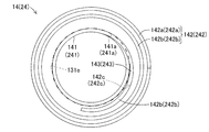
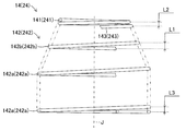
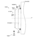
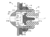
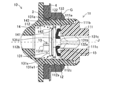
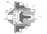
- FIG. 1 is a schematic overall view of a negative pressure booster according to the present invention. It is sectional drawing which shows roughly the structure of the non-return valve assembled in the negative pressure type booster of FIG. It is a figure for demonstrating the winding diameter of the spring which comprises the non-return valve of FIG. It is a figure for demonstrating the winding pitch of the spring which comprises the non-return valve of FIG. It is a figure for demonstrating the positional relationship of the winding around part of a spring, an expansion-contraction winding part, a connection winding part, the flange part of a valve body, and a spring seat. It is sectional drawing which concerns on the modification of embodiment, and shows roughly the structure of the non-return valve assembled in the negative pressure type booster of FIG.
- a negative pressure type booster 2 connected to a negative pressure source 1 of a vehicle is connected to a hollow booster shell 4 in which a negative pressure inlet 3 is formed, and one side is connected to the negative pressure source 1.
- a stop valve 10 Reversely connected to the connected connecting pipe T and the other connected to the negative pressure inlet 3 of the negative pressure booster 2 and disposed in a flow path connecting the negative pressure source 1 and the negative pressure inlet 3
- the stop valve 10 is provided.
- the negative pressure source 1 is, for example, an engine manifold or the like and generates negative pressure.
- the inside of the booster shell 4 is divided by the movable partition 5 into a negative pressure chamber 6 and a variable pressure chamber 7.
- a negative pressure inlet 3 is provided in the negative pressure chamber 6.
- the negative pressure inlet 3 is formed on the wall surface of the booster shell 4 that forms the negative pressure chamber 6, and communicates the inside and the outside of the negative pressure chamber 6. ing.
- the booster piston 8 is connected to the movable partition 5.
- the booster piston 8 is provided so as to be movable relative to the booster shell 4, and one end side of the input rod is connected via a control valve (not shown).
- a brake pedal P is connected to the other end of the input rod 9.
- the input rod 9 retracts together with the brake pedal P. Then, the control valve (not shown) controls the variable pressure chamber 7 and the negative pressure chamber 6 to have the same pressure, and the booster piston 8 also returns to the retracted position.
- the control valve controls the variable pressure chamber 7 and the negative pressure chamber 6 to have the same pressure, and the booster piston 8 also returns to the retracted position.
- the brake pedal P is depressed, the input rod 9 advances with the brake pedal P.
- atmospheric pressure is introduced into the variable pressure chamber 7 by the switching operation of the control valve (not shown), and the pressure difference (negative pressure difference) between the variable pressure chamber 7 and the negative pressure chamber 6 causes the booster piston 8 to move forward. Be driven.
- the check valve 10 allows communication of the atmosphere from the side of the negative pressure booster 2 to the side of the negative pressure source 1 while the atmosphere from the side of the negative pressure source 1 to the side of the negative pressure booster 2 It is a valve mechanism which shuts off the communication of. For this reason, the check valve 10 opens the valve to allow air communication from the negative pressure chamber 6 to the connecting pipe T, so the air in the negative pressure chamber 6 flows toward the negative pressure source 1.
- the air in the negative pressure chamber 6 is sucked by the negative pressure source 1, and the pressure in the negative pressure chamber 6 is made equal to the pressure (negative pressure) as that of the negative pressure source 1. Also, for example, when the pressure of the negative pressure source 1 becomes higher than the pressure of the negative pressure chamber 6 with the stop of the engine, the check valve 10 is closed to close the atmosphere from the connecting pipe T to the negative pressure chamber 6. Since the communication is shut off, the pressure (negative pressure) of the negative pressure chamber 6 is maintained.
- the check valve 10 is airtightly assembled to the negative pressure inlet 3 formed in the booster shell 4 via the grommet G.
- the check valve 10 includes a main body 11, a valve seat 12, a valve body 13, and a spring 14 as an urging member.
- the main body 11 is configured of a first main body portion 111 and a second main body portion 112.
- the first main body portion 111 is formed in a tubular shape, and includes a projecting portion 111 a, a flange portion 111 b, and a first passage 111 c.
- the protrusion 111 a is connected to the second main body 112.
- the flange portion 111 b is in contact with the second main body portion 112.
- the first passage 111 c constituting the passage communicates the inside and the outside of the negative pressure chamber 6.
- the second main body portion 112 is formed in a tubular shape, and a large diameter storage portion 112a, a second passage 112b communicating with the storage portion 112a, and a fitting portion formed at the open end of the storage portion 112a And 112c.
- the second main body portion 112 is integrally fixed to the first main body portion 111 in a state in which the second main body portion 112 is airtightly fitted to the outer peripheral side of the projecting portion 111 a of the first main body portion 111 on the inner surface side of the fitting portion 112 c.
- the accommodating portion 112 a is configured to accommodate the valve seat 12, the valve body 13 and the spring 14.
- the second passage 112 b constituting the passage communicates with the connecting pipe T connected to the negative pressure source 1.
- the valve seat 12 is formed in the first passage 111c and the second passage 112b. Specifically, the valve seat 12 is formed on the tip end surface of the projection 111 a of the first main body 111 housed in the housing 112 a of the second main body 112.
- the tip surface of the protrusion 111a has a dihedral angle of zero with a plane orthogonal to the axis J of the first passage 111c of the first main body 111, which is the axis of the passage. That is, the tip end surface of the projecting portion 111a is orthogonal to the axis J of the first passage 111c.
- the valve body 13 includes a base portion 131, a disc portion 132 and a protrusion 133.
- the disk portion 132 and the protrusion 133 are integrally formed of the same elastic material, for example, the same rubber material.
- the base portion 131 includes a large diameter portion 131a accommodated in the accommodation portion 112a of the second main body portion 112, a small diameter portion 131b inserted through the first passage 111c of the first main body portion 111, and a large diameter portion 131a and a small diameter portion 131b. And a cylindrical neck 131c formed therebetween.
- the large diameter portion 131a, the small diameter portion 131b, and the neck portion 131c are disposed coaxially with the axis line J of the first passage 111c.
- a spring seat 131d as a locking portion for seating a seat winding portion 141 described later of the spring 14 is formed on the surface opposite to the surface connected to the neck portion 131c. ing.
- the spring seat 131d is formed in a groove shape along the circumferential direction by the large diameter portion 131a and the disk-like flange portion 131e opposed to the large diameter portion 131a.
- the spring seat 131d has a groove width in the direction along the axis J larger than the length in the direction along the axis J of the end winding 141 when the end winding 141 of the spring 14 described later is accommodated. Formed as. In the present embodiment, for convenience, the “axis of the passage” and the “axis of the biasing member” are coaxial, and both will be described as the “axis J”.
- the flange portion 131e has a tapered portion 131e1 whose outer diameter decreases toward the direction away from the spring seat 131d along the axis J, that is, toward the telescopic winding portion 142 described later of the spring 14 at the outer peripheral end.
- the tapered portion 131e1 locks the wound portion 141 of the spring 14 to the spring seat 131d
- the diameter of the wound portion 141 is increased along with the movement of the wound portion 141 in the direction along the axis J.
- the end-wound portion 141 exceeding the tapered portion 131e1 is locked to the groove-shaped spring seat 131d by reducing the diameter.
- the maximum outer diameter of the tapered portion 131e1 is formed to be smaller than the inner diameter of a connection winding portion 143 described later of the spring 14, and the state where the end winding portion 141 is engaged with the spring seat 131d, ie, the spring When the valve 14 is assembled to the valve body 13, it does not contact the connecting winding portion 143.
- a plurality of cylindrical legs 131 f are provided on the flange 131 e of the base 131 on the surface opposite to the surface on which the spring seat 131 d is formed.
- the valve body 13 opens. It is provided so as not to block the second passage 112b.
- the leg portion 131 f is formed of an elastic member (for example, a rubber material or the like) in order to prevent noise generated when the valve body 13 is opened and abuts on the inner surface of the second main body portion 112.
- the disc portion 132 is a disc having a diameter larger than that of the first passage 111c of the first main body portion 111, and as shown in FIG. 2, a through hole through which the neck portion 131c of the base portion 131 is airtightly penetrated in the central portion. 132a is formed. Further, the disk portion 132 is formed in an umbrella shape with the formation position of the through hole 132a as a vertex, and the protrusion 133 is integrally formed at the outer peripheral end.
- the protrusion 133 is formed so as to protrude opposite to the valve seat 12 in the state accommodated in the second main body portion 112, and in the sitting state in which the valve body 13 is seated on the valve seat 12, the valve seat 12 To form a contact surface so as to make a tight seal.
- the spring 14 as a biasing member is a helically formed coil spring.
- the spring 14 is assembled in the housing portion 112 a of the second main body portion 112 in a pre-compressed state, and biases the valve body 13 toward the valve seat 12.
- the spring 14 includes, as shown in FIG. 3 and FIG. 4, a wound end portion 141, an extension wound portion 142, and a connection wound portion 143.
- the end winding portion 141 is accommodated in a spring seat 131 d provided on the base portion 131 of the valve body 13, and the spring 14 is engaged with the valve body 13.
- the wound portion 141 is smaller than the outer diameter of the flange portion 131e constituting the spring seat 131d, specifically, the maximum outer diameter of the tapered portion 131e1, and the outer diameter of the spring seat 131d (corresponding to the groove depth) It has a larger inside diameter than that.
- the end winding portion 141 is formed such that the length in the direction along the axis J is smaller than the groove width of the spring seat 131 d.
- the end winding portion 141 is the first turn of the spiral spring 14 as shown in FIG.
- this embodiment although it comprises with the wire which wound the end-winding part 141 once, it is also possible to comprise with the wire which wound several times.
- the telescopic winding portion 142 is separated from the flange portion 131 e in the direction along the axis J, and along with the valve body 13 taking a seat (opening) from the valve seat 12, it is While being compressed from the compressed state, the valve body 13 extends along the direction of the axis J to a pre-compressed state as the valve body 13 is seated (closed) on the valve seat 12.
- the telescopic winding portion 142 has a straight portion 142a parallel to the axis J, that is, having a constant outer diameter and an inner diameter along the direction of the axis J.
- the telescopic winding portion 142 is inclined with respect to the axis J, that is, the diameter of the straight portion 142a is gradually reduced from the outer diameter and the inner diameter of the straight portion 142 along the direction of the axis J. (More specifically, it has a tapered portion 142b having an inner diameter larger than (the maximum outer diameter of the tapered portion 131e1).
- the tapered portion 142 b is an interval of the wire in the direction along the axis J Are formed to have a winding pitch L1 representing.
- the straight portion 142a has a winding pitch L3 which is smaller than the winding pitch L1 of the tapered portion 142b and larger than the winding pitch L2 described later of the connecting winding portion 143 in the free state. It is molded as.
- connection winding portion 143 includes a winding end portion 141a of the end winding portion 141 serving as a base point separated from the spring seat 131d, and an expandable winding portion 142 separated from the flange portion 131e on the valve body 13 side (more specifically, a taper It connects with the winding end portion 142c of the portion 142b) and separates from the flange portion 131e and the spring seat 131d.
- the connection winding portion 143 is the second turn of the spiral spring 14 as shown in FIG.
- this embodiment although it comprises by the wire which wound the connection winding part 143 once, it is also possible to comprise by the wire which wound several times.
- the inner diameter of the end on the side of the end winding portion 141 is smaller than the outer diameter of the flange portion 131 e, and the side of the expansion and contraction winding portion 142 (more specifically, the tapered portion 142 b)
- the inner diameter of the end of the spring is larger than the outer diameter of the flange portion 131e (more specifically, the maximum outer diameter of the tapered portion 131e1 formed at the outer peripheral end) constituting the spring seat 131d It is smaller than the minimum outside diameter in the part 142b.
- the winding pitch L2 of the connecting winding portion 143 is formed to be smaller than the winding pitch L1 of the stretch winding portion 142 in the free state.
- the winding pitch L2 of the connection winding part 143 is smaller than the winding pitch L1 of the expansion-contraction winding part 142, and winding pitch L4 (illustration omitted) It is molded to be larger than).
- the connecting winding portion 143 does not abut on the tapered portion 131e1 of the flange portion 131e, the contracting operation of the telescopic winding portion 142 (the tapered portion 142b) is not affected. Therefore, in order for the spring 14 to bias the valve body 13 by a preset biasing force (elastic force), the check valve 10 is moved from the first passage 111c to the second passage 112b based on the preset operating characteristics. Allow atmospheric communication.
- the negative pressure source 1 When time passes after the depression operation of the brake pedal P is started, the negative pressure source 1 sucks the air, so the pressure difference (negative pressure difference) between the negative pressure chamber 6 and the negative pressure source 1 gradually Smaller. Therefore, the pressure difference (negative pressure difference) between the first passage 111c and the second passage 112b also gradually decreases. As described above, when the pressure difference (negative pressure difference) between the first passage 111c and the second passage 112b gradually decreases, the valve body 13 receives the biasing force of the spring 14 from the second passage 112b side to the first passage 111c side. Gradually, i.e., toward seating on the valve seat 12.
- the atmosphere flows from the negative pressure chamber 6 to the negative pressure source 1 via the negative pressure inlet 3.
- the negative pressure source 1 for example, the manifold of the engine, etc.
- the magnitude of the pressure acting on the valve body 13 from the flowing atmosphere and the magnitude of the biasing force acting on the valve body 13 from the spring 14 The balance may be lost.
- the stretchable winding portion 142 of the spring 14 may vibrate.
- connection winding portion 143 is separated from the flange portion 131e also against such vibration of the spring 14 (the extension winding portion 142), the connection winding portion 143 repeatedly abuts on the flange portion 131e and the valve body 13 And the occurrence of abnormal noise and the like due to the valve body 13 repeatedly contacting the valve seat 12 is suppressed.
- the negative pressure source 1 continues to take in the atmosphere, so the pressure difference between the negative pressure chamber 6 and the negative pressure source 1 continues. (Negative pressure difference) becomes smaller. Therefore, in this case, the pressure difference (negative pressure difference) between the first passage 111c and the second passage 112b is also smaller.
- the valve body 13 is seated by the biasing force of the spring 14. Thereby, the check valve 10 blocks the communication of the atmosphere from the negative pressure chamber 6 to the negative pressure source 1 through the negative pressure inlet 3, that is, from the first passage 111c to the second passage 112b.
- the negative pressure source 1 continues to inhale the atmosphere present in the second passage 112b.
- negative pressure pulsation (for example, in-air resonance) may occur in the second passage 112 b connected to the connection pipe T due to the suction cycle of the atmosphere by the negative pressure source 1.
- the negative pressure pulsation generated in this manner acts to excite vibration on the spring 14 in the seated state.
- the stretchable winding portion 142 of the spring 14 vibrates due to such negative pressure pulsation, the end winding portion 141 presses the large diameter portion 131 a of the base portion 131 in the direction of the axis J.
- the telescopic winding portion 142 and the connection winding portion 143 are separated from the flange portion 131e and the spring seat 131d, repeated contact of the telescopic winding portion 142 and the connection winding portion 143 with the flange portion 131e is avoided. Therefore, even if the expansion wound portion 142 of the spring 14 vibrates due to negative pressure pulsation, the spring 14 does not vibrate the valve body 13, and as a result, the valve body 13 vibrates. Generation of sound etc. is suppressed.
- the negative pressure type booster 2 includes a hollow booster shell 4 and a movable unit that airtightly divides the booster shell 4 into the negative pressure chamber 6 and the variable pressure chamber 7. It communicates with a booster piston 8 provided so as to be movable relative to the partition 5 and the booster shell 4 and integrally moving with the movable partition 5 inside the booster shell 4 and a negative pressure chamber 6 of the booster shell 4 It is assembled to the negative pressure inlet 3 and connected to the negative pressure source 1 of the vehicle, allowing air communication from the negative pressure inlet 3 to the negative pressure source 1 while introducing negative pressure from the negative pressure source 1 And a check valve 10 for blocking the communication of the atmosphere toward the port 3.
- the check valve 10 is formed in the main body 11 provided so as to be connected to the negative pressure inlet 3 and the main body 11, and is a first passage as a passage communicating the negative pressure inlet 3 with the negative pressure source 1. 111c and the second passage 112b, the valve seat 12 formed in the passage, and a cylindrical member housed in the passage and seated or released from the valve seat 12 and extending into the passage in the direction of the axis J Base portion 131, a disk portion 132 extending along the radial direction of the base portion 131, an annular protrusion 133 projecting toward the valve seat 12 from the outer peripheral end of the disk portion 132, and along the radial direction of the base portion 131 A valve body 13 including a spring seat 131d as a groove-like locking portion provided in the base portion 131 including the flange portion 131e and the disk portion 132 which are extended so as to face the disk portion 132; So that the projection 133 is in contact with the valve seat 12 And a spring 14 as a helical bias
- the spring 14 contacts the wound portion 141 locked to the spring seat 131d and the main body 11.
- an expansion-contraction winding part 142 which is separated from the flange part 131e and expands and contracts according to seating or leaving of the valve body 13, and a winding end portion 141a of the winding part 141 which becomes a base point apart from the spring seat 131d 13 is configured to connect with the winding end portion 142c of the telescopic winding portion 142 separated from the flange portion 131e and to include a connection winding portion 143 separated from the flange portion 131e and the spring seat 131d.
- the telescopic winding portion 142 is composed of a straight portion 142a parallel to the axis J of the spring 14 and a tapered portion 142b inclined to the axis J
- the portion 143 can connect the wound end portion 141 a of the end-wound portion 141 and the wound end portion of the tapered portion 142 b of the stretchable wound portion 142.
- the inner diameter of the end portion on the side of the end winding portion 141 is smaller than the outer diameter of the flange portion 131e, and the inner diameter of the end portion on the side of the expandable winding portion 142 is outside the flange portion 131e. It is larger than the diameter and smaller than the minimum outer diameter of the tapered portion 142b.
- connection winding portion 143 connecting the end winding portion 141 and the extension winding portion 142 of the spring 14 can be separated from the flange portion 131 e of the valve body 13.
- the telescopic winding portion 142 and the connection winding portion 143 do not contact (interfere with) the flange portion 131 e of the valve body 13.
- the operation characteristic set in the check valve 10 that is, the valve 14 is imparted from the spring 14 when seated on or away from the valve seat 12. Bias force (load characteristics) does not change. Accordingly, the check valve 10 can exhibit good operating characteristics.
- the winding pitch of the connecting winding portion 143 in the direction along the axis J of the spring 14 The size of L2 is set to be smaller than the size of the winding pitch L1 of the telescopic winding portion 142.
- the winding pitch L2 of the connection winding part 143 is set larger than the size of the winding pitch L4 of the end winding parts 141.
- connection winding portion 143 can be further separated from the flange portion 131 e in the direction along the axis J.
- the tapered portion 142b and the connection winding portion 143 of the telescopic winding portion 142 are reliably separated from the flange portion 131e in the direction along the axis J and in the radial direction perpendicular to the axis J, and more reliably with the flange portion 131e. Abutment (interference) can be avoided.
- the length of the end winding portion 141 in the direction along the axis J of the spring 14 is smaller than the groove width of the spring seat 131 d while being locked to the spring seat 131 d of the base 131. It is formed.
- the flange portion 131 e has a tapered portion 131 e 1 at the outer peripheral end, the outer diameter of which decreases in the direction of separating from the spring seat 131 d along the axis J.
- the connecting winding portion 143 connected to the winding end portion 142c of the telescopic winding portion 142 can be reliably separated from the flange portion 131e. it can. Therefore, contact (interference) of the connection winding portion 143 with the flange portion 131 e can be more reliably avoided.
- the non-return valve 10 might be equipped with the valve body 13 comprised from the base 131, the disk part 132, and the protrusion 133.
- FIG. instead of this, it is also possible to integrally form the base, the disk portion and the projection from a rubber material which is an elastic material. That is, in this modification, as shown in FIG. 6, the check valve 20 is a single-piece product integrally formed with the base portion 231, the disk portion 232, the projection portion 233, the flange portion 234, the spring seat 235 and the leg portion 236. It differs from the check valve 10 of the above embodiment in that it has a certain valve body 23.
- the non-return valve 20 is airtightly assembled via the grommet G with respect to the negative pressure inlet 3 formed in the booster shell 4, as shown to FIG. 1 and FIG.
- the non-return valve 20 is equipped with the main body 21, the valve seat 22, the valve body 23, and the spring 24, as shown in FIG.
- the main body 21 is composed of a first main body portion 211 and a second main body portion 212.
- the first main body portion 211 and the second main body portion 212 correspond to the first main body portion 111 and the second main body portion 112 which constitute the main body 11 of the above embodiment, and the configurations thereof are the same.
- the projecting portion 211a, the flange portion 211b and the first passage 211c of the first main body portion 211 correspond to the projecting portion 111a, the flange portion 111b and the first passage 111c of the first main body portion 111 in the above embodiment,
- the configuration is the same.
- the housing 212a, the second passage 212b and the fitting 212c of the second main body 212 correspond to the housing 112a, the second passage 112b and the fitting 112c of the second main body 112 in the above embodiment,
- the configuration is the same.
- corresponds to the valve seat 12 of the said embodiment, and the structure is the same.
- the spring 24 corresponds to the spring 14 of the above embodiment, and the configuration is the same.
- the wound portion 241 of the spring 24, the expansion / contraction winding portion 242 (straight portion 242a and tapered portion 242b), the connection winding portion 243, the winding end portion 241a and the winding end portion 242c are the seat of the spring 14 of the above embodiment.
- the structure corresponds to the winding portion 141, the expansion and contraction winding portion 142 (the straight portion 142a and the tapered portion 142b), the connection winding portion 143, the winding end portion 141a, and the winding end portion 142c.
- the valve body 23 includes a base portion 231, a disk portion 232, a protrusion 233, a flange portion 234, a spring seat 235, and a leg portion 236.
- the base portion 231, the disk portion 232, the projection portion 233, the flange portion 234, the spring seat 235 and the leg portion 236, that is, the valve body 23 are integrally formed of a rubber material which is an elastic member.
- the rubber material forming the valve body 23 is preferably a rubber material having high rigidity.
- the atmosphere flows from the negative pressure source 1 toward the negative pressure chamber 6, that is, the pressure in the second passage 212 b is in the first passage 211 c. It is preferable to select a rubber material having such rigidity that the valve body 23 is not deformed and displaced in the first passage 211c in a situation where the pressure is higher than the pressure.
- the base portion 231 is formed in a solid cylindrical shape so as to extend in the direction of the axis line J of the first passage 211c, and the tip end side thereof enters into the first passage 211c of the first main body portion 211.
- the disk portion 232 is formed to extend in the radial direction of the base 231 on the proximal end side of the base 231.
- the protrusion 233 is annularly formed at the outer peripheral end of the disk portion 232.
- the protrusion 233 is formed to protrude in the state of being accommodated in the second main body portion 212 so as to face the valve seat 22, and in the seating state in which the valve body 23 is seated on the valve seat 22, the valve seat It is supposed to contact 22. Further, when the valve body 23 is in a seated state, the protrusion 233 forms a contact surface with the valve seat 22 to seal airtightly.
- the flange portion 234 is smaller in diameter than the outer diameter of the disc portion 232, and forms a spring seat 235 which engages with the wound portion 241 of the spring 24 together with the disc portion 232 of the valve body 23.
- a tapered portion 234 a is provided at the outer peripheral end of the flange portion 234. In the leg portion 236, when atmospheric pressure is introduced into the variable pressure chamber 7 of the negative pressure type booster 2 and a large amount of air flows from the first passage 211c toward the second passage 212b, the valve body 23 opens. It is provided so as not to block the second passage 212b.
- connection winding portion 243 of the spring 24 is prevented from coming into contact (interference) with the flange portion 234 as in the above embodiment. Therefore, the same effect as that of the above embodiment can be obtained.
- connection winding portion 143 of the spring 14 does not contact (interference) with the spring seat 131 d and the flange portion 131 e of the base portion 131 of the valve body 13 (valve body 23).
- the unit 142 is connected.
- the connecting winding portion 243 of the spring 24 connects the end winding portion 241 and the extension winding portion 242 so as not to abut (interfere with) the spring seat 235 and the flange portion 234 of the valve body 23. .
- valve body 13 for example, in the sitting state in which the valve body 13 (valve body 23) is seated on the valve seat 12 (valve seat 22).
- a vibration absorbing portion 15 vibration that absorbs more vibration applied to the valve 13 (valve 23) at a part of the valve 13 (valve 23) than other parts of the valve 13 (valve 23) It is also possible to provide an absorber 25).
- a thin-walled portion having a smaller plate thickness than the other portion is formed as a vibration absorbing portion 15 in a part of the disc portion 132.
- the vibration absorbing portion 15 has low rigidity, even if the protrusion 133 in the vicinity of the vibration absorbing portion 15 repeats the separation and seating with respect to the valve seat 12 with the vibration of the vibration absorbing portion 15, The impact load that the projection 133 applies to the valve seat 12 at the time of seating decreases. Therefore, the generation of the contact noise due to the vibration of the valve 13 can be suppressed.
- the vibration absorbing portion 25 has low rigidity, even if the protrusion 233 in the vicinity of the vibration absorbing portion 25 repeats the separation and seating on the valve seat 22 with the vibration of the vibration absorbing portion 25, The impact load that the projection 233 applies to the valve seat 12 at the time of seating decreases. Therefore, it is possible to suppress the generation of the contact noise caused by the vibration of the valve body 23.
- the check valve 10 and the check valve 20 are assembled to the negative pressure introduction port 3 formed in the booster shell 4 of the negative pressure type booster 2 via the grommet G. did.
- the booster shell 4 of the negative pressure type booster 2 is made of resin, for example, it is possible to integrally form the first main body portions 111 and 211 with the booster shell 4. According to this, there is no need to fix the first main body portion 111, 211 to the booster shell 4, and the manufacturing cost can be reduced.
- the check valve 10 and the check valve 20 are directly assembled to the negative pressure booster 2.
Landscapes
- Engineering & Computer Science (AREA)
- Mechanical Engineering (AREA)
- General Engineering & Computer Science (AREA)
- Transportation (AREA)
- Check Valves (AREA)
- Springs (AREA)
- Braking Systems And Boosters (AREA)
- Valves And Accessory Devices For Braking Systems (AREA)
- Details Of Valves (AREA)
Abstract
負圧式倍力装置2の逆止弁10は、負圧導入口3に組み付けられた本体11と、第一通路111c、収容部112a及び第二通路112bと、第一通路111cに形成される弁座12と、収容部112a内に収容される弁体13と、弁体13を弁座12に向けて付勢するスプリング14とを備えている。スプリング14は、ばね座131dに係止される座巻部141、弁体13のフランジ部131eから離間して伸縮する伸縮巻部142、及び、フランジ部131e及びばね座131dから離間して座巻部141と伸縮巻部142とを連結する連結巻部143を含むように構成される。
Description
本発明は、負圧式倍力装置に関する。
従来から、例えば、下記特許文献1に開示された逆止弁付負圧ブースタが知られている。これらの従来の負圧ブースタに組み付けられる逆止弁は、ハウジング本体内に負圧出口孔(負圧出口ポート)と負圧出口孔(負圧出口ポート)に形成された弁座とを有し、この弁座と協働する弁体及び弁体を弁座に着座させるための弁ばねを収容するようになっている。そして、上記特許文献1に開示された逆止弁では、負圧源の間欠的な吸気作用により発生する弁ばね及び弁体の振動を抑制するために、弁ばねのコイル巻きピッチを異ならせることによって弁ばね及び弁体の共振を抑制するようになっている。
ところで、負圧源と負圧式倍力装置との間に設けられる逆止弁は、弁体が弁座から完全に離座していない状態又は着座状態において、負圧源の間欠的な吸気作用(負圧脈動)に起因して弁ばねが伸縮し、伸縮時に弁ばねの端部(座巻部の側の端部)が弁体の係止用の溝部(係止部)や弁体の外周部(フランジ部)に当接して弁体を振動させる可能性があり、弁体が弁座に対して着座と離座を繰り返す場合がある。このように、弁体の全体が振動し、弁体の全体が弁座に対して着座と離座とを繰り返す状態では、弁体と弁座とが当接することによって異音(当接音)が発生する虞がある。
本発明は、上記課題を解決するためになされたものである。即ち、本発明の目的は、負圧脈動に起因する逆止弁の振動及び異音(当接音)の発生を抑制することが可能な負圧式倍力装置を提供することにある。
上記の課題を解決するため、本発明に係る負圧式倍力装置は、中空状のブースタシェルと、ブースタシェルを負圧室と変圧室とに気密的に区画する可動隔壁と、ブースタシェルに対して相対移動可能に設けられ、且つ、ブースタシェルの内部にて可動隔壁とともに一体に移動するブースタピストンと、ブースタシェルの負圧室に連通する負圧導入口に組み付けられるとともに車両の負圧源と接続され、負圧導入口から負圧源に向けての大気の連通を許可する一方で、負圧源から負圧導入口に向けての大気の連通を遮断する逆止弁と、を備えた負圧式倍力装置であって、逆止弁は、負圧導入口に接続するように設けられた本体と、本体に形成されて、負圧導入口と負圧源とを連通させる通路と、通路に形成される弁座と、通路内に収容されて弁座に着座又は離座し、軸線の方向にて通路内に向けて延出する円筒状の基部、基部の径方向に沿って延出する円盤部、円盤部の外周端部から弁座に向けて突出する環状の突部、及び、基部の径方向に沿って延出して円盤部に対向するフランジ部と円盤部とを含んで基部に設けられた溝状の係止部を含んで構成された弁体と、通路内に収容されて突部を弁座に接触させるように弁体を弁座に向けて付勢する螺旋状の付勢部材と、を備え、付勢部材は、係止部に係止される座巻部と、本体に接触するとともにフランジ部から離間していて弁体の着座又は離座に応じて伸縮する伸縮巻部と、係止部から離間する基点となる座巻部の巻き端部分と弁体の側においてフランジ部から離間した伸縮巻部の巻き端部分とを連結するとともに、フランジ部及び係止部から離間する連結巻部と、を含むように構成される。
これによれば、付勢部材の座巻部と伸縮巻部とを連結する連結巻部は、弁体のフランジ部から離間することができる。これにより、弁体が弁座に着座している着座状態時に通路内に負圧脈動が生じて付勢部材の伸縮巻部が伸縮して振動する場合、伸縮巻部及び連結巻部は、弁体のフランジ部及び係止部に当接することを避ける(抑制する)ことができる。従って、負圧脈動によって付勢部材の伸縮巻部が伸縮しても、付勢部材が弁体を振動させないので、弁体が弁座に繰り返し当接して発せられる異音(当接音)を抑制することができる。
以下、本発明の実施形態について図面を参照しながら説明する。図1に示すように、車両の負圧源1に接続される負圧式倍力装置2は、負圧導入口3が形成された中空状のブースタシェル4と、一方が負圧源1に接続された接続管Tに接続されるとともに他方が負圧式倍力装置2の負圧導入口3に接続されていて負圧源1と負圧導入口3とを接続する流路に配置される逆止弁10と、を備えている。
負圧源1は、例えば、エンジンのマニホールド等であり、負圧を発生させるものである。ブースタシェル4の内部は、可動隔壁5により負圧室6と変圧室7とに区画されている。負圧室6には、負圧導入口3が設けられる。負圧導入口3は、図1及び図2に示すように、負圧室6を形成するブースタシェル4の壁面に形成されており、負圧室6の内部と外部とを連通するようになっている。図1に戻り、可動隔壁5には、ブースタピストン8が接続されている。ブースタピストン8は、ブースタシェル4に対して相対移動可能に設けられており、図示を省略する制御弁を介して入力ロッドの一端側が接続されている。入力ロッド9の他端側には、ブレーキペダルPが接続されている。
負圧式倍力装置2においては、ブレーキペダルPが踏み込み操作されていない場合には、入力ロッド9がブレーキペダルPとともに後退する。そして、制御弁(図示省略)が変圧室7と負圧室6とを同圧になるように制御することにより、ブースタピストン8も後退位置に戻る。一方、ブレーキペダルPが踏み込み操作された場合には、入力ロッド9がブレーキペダルPとともに前進する。そして、制御弁(図示省略)の切り替え動作により変圧室7に大気圧が導入され、変圧室7と負圧室6との間の圧力差(負圧差)によりブースタピストン8が前進する方向に付勢される。
変圧室7に大気圧が導入されてブースタピストン8が前進すると、変圧室7に導入された大気の一部が負圧室6に流入する。流入した大気は、逆止弁10及び接続管Tを介して負圧源1に向けて流れる。逆止弁10は、負圧式倍力装置2の側から負圧源1の側への大気の連通を許可する一方で、負圧源1の側から負圧式倍力装置2の側への大気の連通を遮断する弁機構である。このため、逆止弁10は開弁することによって負圧室6から接続管Tへの大気の連通を許可するので、負圧室6内の大気は負圧源1に向けて流れる。これにより、負圧室6内の大気が負圧源1によって吸気されて、負圧室6内の圧力は、負圧源1と同等の圧力(負圧)とされる。又、例えば、エンジンの停止に伴って負圧源1の圧力が負圧室6の圧力よりも高くなると、逆止弁10は閉弁することによって接続管Tから負圧室6への大気の連通を遮断するので、負圧室6の圧力(負圧)が維持される。
逆止弁10は、図2に示すように、ブースタシェル4に形成された負圧導入口3に対して、グロメットGを介して気密的に組み付けられている。逆止弁10は、本体11と、弁座12と、弁体13と、付勢部材としてのスプリング14と、を備えている。
本体11は、第一本体部111と、第二本体部112と、から構成される。第一本体部111は、筒状に形成されており、突出部111aと、フランジ部111bと、第一通路111cと、を有する。突出部111aは、第二本体部112と接続される。フランジ部111bは、第二本体部112と当接するようになっている。通路を構成する第一通路111cは、負圧室6の内部と外部とを連通する。
第二本体部112は、筒状に形成されており、大径の収容部112aと、収容部112aに連通する第二通路112bと、収容部112aの開口側端部に形成された嵌合部112cと、を有する。第二本体部112は、嵌合部112cの内面側にて第一本体部111の突出部111aの外周側と気密的に嵌合した状態で、第一本体部111と一体固定される。収容部112aは、弁座12、弁体13及びスプリング14を収容するようになっている。通路を構成する第二通路112bは、負圧源1に接続される接続管Tと連通する。
弁座12は、第一通路111c及び第二通路112bに形成される。具体的に、弁座12は、第二本体部112の収容部112a内に収容された第一本体部111の突出部111aの先端面に形成される。突出部111aの先端面は、通路の軸線である第一本体部111の第一通路111cの軸線Jに対して直交する平面との二面角がゼロになっている。即ち、突出部111aの先端面は、第一通路111cの軸線Jに対して直交するようになっている。
弁体13は、基部131、円盤部132及び突部133から構成される。ここで、円盤部132及び突部133は、同一の弾性材料、例えば、同一のゴム材料で一体に形成される。
基部131は、第二本体部112の収容部112aに収容される大径部131aと、第一本体部111の第一通路111cに挿通される小径部131bと、大径部131aと小径部131bとの間に形成された円柱状の頸部131cと、を備えている。大径部131a、小径部131b及び頸部131cは、第一通路111cの軸線Jに対して同軸に配置されている。
又、基部131の大径部131aには、頸部131cに接続される面と反対側の面において、スプリング14の後述する座巻部141を着座させる係止部としてのばね座131dが形成されている。ばね座131dは、大径部131aと大径部131aに対向する円盤状のフランジ部131eとによって周方向に沿った溝状に形成されている。ばね座131dは、軸線Jに沿った方向における溝幅の大きさが、後述するスプリング14の座巻部141を収容した状態で座巻部141の軸線Jに沿った方向における長さよりも大きくなるように形成される。尚、本実施形態においては、便宜上、「通路の軸線」と「付勢部材の軸線」とは同軸であるとし、共に、「軸線J」として説明する。
フランジ部131eは、外周端部において、軸線Jに沿ってばね座131dから離間する方向、即ち、スプリング14の後述する伸縮巻部142に向けて、外径が小さくなるテーパ部131e1を有している。これにより、テーパ部131e1は、スプリング14の座巻部141をばね座131dに係止する際において、座巻部141の軸線Jに沿った方向への移動に伴って座巻部141を拡径させ、テーパ部131e1を超えた座巻部141は縮径することによって溝状のばね座131dに係止される。又、テーパ部131e1の最大外径は、スプリング14の後述する連結巻部143の内径よりも小さくなるように形成されており、座巻部141がばね座131dに係止した状態、即ち、スプリング14を弁体13に組み付けた状態において、連結巻部143と接触しないようになっている。
更に、基部131のフランジ部131eには、ばね座131dを形成する面と反対側の面において、円柱状の脚部131fが複数設けられる。脚部131fは、負圧式倍力装置2の変圧室7に大気圧が導入されて多量の大気が第一通路111cから第二通路112bに向けて流通する際、開弁した弁体13が第二通路112bを塞がないように設けられる。脚部131fは、弁体13が開弁して第二本体部112の内面に当接した場合に発せられる異音を防止するために、弾性部材(例えば、ゴム材料等)から形成される。
円盤部132は、第一本体部111の第一通路111cよりも大径の円盤とされており、図2に示すように、中心部分に基部131の頸部131cを気密的に貫通させる貫通孔132aが形成されている。又、円盤部132は、貫通孔132aの形成位置を頂点とする傘状に形成されており、外周端部に突部133が一体形成されている。突部133は、第二本体部112に収容された状態において、弁座12に対向して突出するように形成されており、弁体13が弁座12に着座する着座状態において、弁座12に接触するように接触面を形成して気密的にシールするようになっている。
付勢部材としてのスプリング14は、螺旋状に形成されたコイルばねである。スプリング14は、予圧縮された状態で第二本体部112の収容部112aの内部に組み付けられており、弁体13を弁座12に向けて付勢している。スプリング14は、図3及び図4に示すように、座巻部141と、伸縮巻部142と、連結巻部143と、を備えている。
座巻部141は、弁体13の基部131に設けられたばね座131dに収容されて、スプリング14を弁体13に係止される。座巻部141は、ばね座131dを構成するフランジ部131eの外径、具体的には、テーパ部131e1の最大外径よりも小さく、且つ、ばね座131dの外径(溝深さに相当)よりも大きな内径を有している。又、座巻部141は、軸線Jに沿った方向における長さが、ばね座131dの溝幅よりも小さくなるように形成される。ここで、本実施形態において、座巻部141は、図2に示すように、螺旋状のスプリング14の一巻目である。尚、本実施形態においては、座巻部141を一巻きした線材によって構成するが、複数巻きした線材によって構成することも可能である。
伸縮巻部142は、軸線Jに沿った方向において、フランジ部131eから離間しており、弁体13が弁座12から離座(開弁)することに伴って軸線Jの方向に沿って予圧縮状態から圧縮されるとともに、弁体13が弁座12に着座(閉弁)することに伴って軸線Jの方向に沿って予圧縮状態まで伸張する。伸縮巻部142は、図4に示すように、軸線Jに対して平行、即ち、軸線Jの方向に沿って外径及び内径が一定となるストレート部分142aを有している。又、伸縮巻部142は、軸線Jに対して傾斜する、即ち、軸線Jの方向に沿ってストレート部分142aの外径及び内径から徐々に縮径されて弁体13のフランジ部131eの外径(より具体的には、テーパ部131e1の最大外径)よりも大きな内径を有するテーパ部分142bを有している。ここで、テーパ部分142bは、図4に示すように、スプリング14が第二通路112b(より詳しくは、収容部112a)に収容されていない自由状態において、軸線Jに沿った方向における線材の間隔を表す巻きピッチL1となるように成形されている。又、ストレート部分142aは、図4に示すように、自由状態において、テーパ部分142bの巻きピッチL1よりも小さく、且つ、連結巻部143の後述する巻きピッチL2よりも大きい、巻きピッチL3となるように成形されている。
連結巻部143は、ばね座131dから離間する基点となる座巻部141の巻き端部分141aと、弁体13の側においてフランジ部131eから離間した伸縮巻部142(より具体的には、テーパ部分142b)の巻き端部分142cと、を連結するとともに、フランジ部131e及びばね座131dから離間する。本実施形態においては、連結巻部143は、図2に示すように、螺旋状のスプリング14の二巻目である。尚、本実施形態においては、連結巻部143を一巻きした線材によって構成するが、複数巻きした線材によって構成することも可能である。
連結巻部143は、図3に示すように、座巻部141の側の端部の内径がフランジ部131eの外径よりも小さく、伸縮巻部142(より詳しくは、テーパ部分142b)の側の端部の内径がばね座131dを構成するフランジ部131eの外径(より詳しくは、外周端部に形成されたテーパ部131e1の最大外径)よりも大きく、且つ、伸縮巻部142のテーパ部分142bにおける最小外径よりも小さい。ここで、連結巻部143の巻きピッチL2は、図4に示すように、自由状態において、伸縮巻部142の巻きピッチL1よりも小さくなるように成形されている。尚、座巻部141が複数巻きされた場合には、連結巻部143の巻きピッチL2は、伸縮巻部142の巻きピッチL1よりも小さく、且つ、座巻部141の巻きピッチL4(図示省略)よりも大きくなるように成形される。
次に、上記のように構成された逆止弁10の作動を説明する。逆止弁10においては、ブレーキペダルPが踏み込み操作されると、変圧室7に大気圧が導入されて負圧室6に大気が流れるので、負圧室6の大気が本体11の第一通路111cに流れる。これにより、弁体13は、負圧室6の圧力がスプリング14の付勢力よりも大きくなると、弁座12から離座し、負圧導入口3を介して負圧室6から負圧源1に向けて、即ち、第一通路111cから第二通路112bに向けての大気の連通を許可する。
弁体13が弁座12から離座する場合、スプリング14においては、伸縮巻部142のテーパ部分142bが収縮する。この場合、図5に示すように、連結巻部143は、フランジ部131eから離間しているので、伸縮巻部142のテーパ部分142bが収縮することに伴ってばね座131dの方向に押圧されても、フランジ部131eのテーパ部131e1に当接(干渉)しない。又、連結巻部143がフランジ部131eのテーパ部131e1に当接しないことにより、伸縮巻部142(テーパ部分142b)の収縮動作に影響を与えることがない。従って、スプリング14が予め設定された付勢力(弾性力)によって弁体13を付勢するため、逆止弁10は予め設定された作動特性に基づいて第一通路111cから第二通路112bへの大気の連通を許可する。
ブレーキペダルPの踏み込み操作が開始されてから時間が経過すると、負圧源1が大気を吸入しているので、負圧室6と負圧源1との間の圧力差(負圧差)が徐々に小さくなる。従って、第一通路111cと第二通路112bとの間の圧力差(負圧差)も徐々に小さくなる。このように第一通路111cと第二通路112bとの間の圧力差(負圧差)が徐々に小さくなると、弁体13は、スプリング14の付勢力によって第二通路112b側から第一通路111c側に向けて、即ち、弁座12に着座する方向に向けて徐々に変位する。
ところで、このように弁体13が弁座12に着座する方向に変位している状態においても、負圧導入口3を介して負圧室6から負圧源1に向け大気が流れている。そして、負圧源1(例えば、エンジンのマニホールド等)による大気の吸入周期によって、流れている大気から弁体13に作用する圧力の大きさとスプリング14から弁体13に作用する付勢力の大きさとのバランスが崩れる場合がある。この場合、スプリング14の伸縮巻部142が振動する可能性がある。このようなスプリング14(伸縮巻部142)の振動に対しても、連結巻部143は、フランジ部131eから離間しているので、連結巻部143がフランジ部131eに繰り返し当接して弁体13を振動させることがなく、弁体13が弁座12に繰り返し当接することによる異音等の発生が抑制される。
ブレーキペダルPの踏み込み操作が開始されてから更に時間が経過した場合においては、引き続き、負圧源1が大気を吸入しているので、負圧室6と負圧源1との間の圧力差(負圧差)がより小さくなる。従って、この場合には、第一通路111cと第二通路112bとの間の圧力差(負圧差)もより小さくなる。このように第一通路111cと第二通路112bとの間の圧力差(負圧差)がより小さくなると、弁体13はスプリング14の付勢力によって着座状態になる。これにより、逆止弁10は、負圧導入口3を介して負圧室6から負圧源1に向けて、即ち、第一通路111cから第二通路112bに向けての大気の連通を遮断する。
そして、着座状態においても、負圧源1は第二通路112b内に存在している大気を吸入し続ける。このとき、負圧源1による大気の吸入周期によって接続管Tに接続された第二通路112b内に負圧脈動(例えば、気中共鳴)が発生する場合がある。このように発生する負圧脈動は、着座状態にあるスプリング14に対して振動を励起するように作用する。このような負圧脈動によってスプリング14の伸縮巻部142が振動する場合、座巻部141は基部131の大径部131aを軸線Jの方向に沿って押圧している。又、伸縮巻部142及び連結巻部143は、フランジ部131e及びばね座131dから離間しているので、伸縮巻部142及び連結巻部143がフランジ部131eに繰り返し当接することが避けられる。従って、負圧脈動に起因してスプリング14の伸縮巻部142が振動した場合であっても、スプリング14が弁体13を振動させることがなく、その結果、弁体13が振動することによる異音等の発生が抑制される。
以上の説明からも理解できるように、上記実施形態の負圧式倍力装置2は、中空状のブースタシェル4と、ブースタシェル4を負圧室6と変圧室7とに気密的に区画する可動隔壁5と、ブースタシェル4に対して相対移動可能に設けられ、且つ、ブースタシェル4の内部にて可動隔壁5とともに一体に移動するブースタピストン8と、ブースタシェル4の負圧室6に連通する負圧導入口3に組み付けられるとともに車両の負圧源1と接続され、負圧導入口3から負圧源1に向けての大気の連通を許可する一方で、負圧源1から負圧導入口3に向けての大気の連通を遮断する逆止弁10と、を備える。
逆止弁10は、負圧導入口3に接続するように設けられた本体11と、本体11に形成されて、負圧導入口3と負圧源1とを連通させる通路としての第一通路111c及び第二通路112bと、通路に形成される弁座12と、通路内に収容されて弁座12に着座又は離座し、軸線Jの方向にて通路内に向けて延出する円筒状の基部131、基部131の径方向に沿って延出する円盤部132、円盤部132の外周端部から弁座12に向けて突出する環状の突部133、及び、基部131の径方向に沿って延出して円盤部132に対向するフランジ部131eと円盤部132とを含んで基部131に設けられた溝状の係止部としてのばね座131dを含んで構成された弁体13と、通路内に収容されて突部133を弁座12に接触させるように弁体13を弁座12に向けて付勢する螺旋状の付勢部材としてのスプリング14と、を備え、スプリング14は、ばね座131dに係止される座巻部141と、本体11に接触するとともにフランジ部131eから離間していて弁体13の着座又は離座に応じて伸縮する伸縮巻部142と、ばね座131dから離間する基点となる座巻部141の巻き端部分141aと弁体13の側においてフランジ部131eから離間した伸縮巻部142の巻き端部分142cとを連結するとともに、フランジ部131e及びばね座131dから離間する連結巻部143と、を含むように構成される。
この場合、より具体的には、伸縮巻部142は、スプリング14の軸線Jに対して平行なストレート部分142aと、軸線Jに対して傾斜するテーパ部分142bと、から構成されており、連結巻部143は、座巻部141の巻き端部分141aと伸縮巻部142のテーパ部分142bの巻き端部分とを連結することができる。そして、この場合、連結巻部143は、座巻部141の側の端部の内径がフランジ部131eの外径よりも小さく、伸縮巻部142の側の端部の内径がフランジ部131eの外径よりも大きく、且つ、テーパ部分142bにおける最小外径よりも小さい。
これらによれば、座巻部141とスプリング14の伸縮巻部142とを連結する連結巻部143は、弁体13のフランジ部131eから離間することができる。これにより、弁体13が弁座12に着座している着座状態時に第一通路111c及び第二通路112b内に負圧脈動が生じてスプリング14の伸縮巻部142が伸縮して振動する場合、伸縮巻部142、及び、伸縮巻部142と座巻部141とを連結する連結巻部143は、弁体13のフランジ部131e及びばね座131dに当接することを避ける(抑制する)ことができる。従って、負圧脈動によってスプリング14が伸縮しても、スプリング14が弁体13を振動させないので、弁体13が弁座12に繰り返し当接して発せられる異音(当接音)を抑制することができる。
又、伸縮巻部142及び連結巻部143は、弁体13のフランジ部131eと当接(干渉)しない。これにより、伸縮巻部142の伸縮動作は何ら阻害されないため、逆止弁10に設定された作動特性、即ち、弁体13が弁座12に着座又は離座する際にスプリング14から付与される付勢力(荷重特性)が変化することがない。従って、逆止弁10は、良好な作動特性を発揮することができる。
この場合、スプリング14が第一通路111c及び第二通路112b内即ち本体11の収容部112a内に収容されていない自由状態において、スプリング14の軸線Jに沿った方向における連結巻部143の巻きピッチL2の大きさは、伸縮巻部142の巻きピッチL1の大きさよりも小さく設定される。尚、座巻部141が複数巻きされて構成される場合、連結巻部143の巻きピッチL2は、座巻部141の巻きピッチL4の大きさよりも大きく設定される。
これによれば、連結巻部143は、軸線Jに沿った方向において、フランジ部131eからより離間することができる。これにより、伸縮巻部142のテーパ部分142b及び連結巻部143は、軸線Jに沿った方向及び軸線Jに垂直な径方向においてフランジ部131eから確実に離間し、より確実にフランジ部131eとの当接(干渉)を回避することができる。
これらの場合、座巻部141は、基部131のばね座131dに係止された状態で、スプリング14の軸線Jに沿った方向における長さが、ばね座131dの溝幅よりも小さくなるように形成される。
これによれば、座巻部141は、基部131のばね座131dに係止された状態において、スプリング14が負圧脈動に起因して振動する場合であっても、ばね座131dに当接(干渉)しない。従って、弁体13を振動させることがなく、異音の発生をより確実に抑制することができる。
又、これらの場合、フランジ部131eは、外周端部において、軸線Jに沿ってばね座131dから離間する方向において外径が小さくなるテーパ部131e1を有する。
これによれば、フランジ部131eの外周端部にテーパ部131e1が設けられることにより、伸縮巻部142の巻き端部分142cに連結される連結巻部143をフランジ部131eから確実に離間させることができる。従って、連結巻部143がフランジ部131eに当接(干渉)することをより確実に回避することができる。
(変形例)
上記実施形態においては、逆止弁10が基部131、円盤部132及び突部133から構成される弁体13を備えるように実施した。これに代えて、基部、円盤部及び突部を弾性材料であるゴム材料で一体形成することも可能である。即ち、この変形例では、図6に示すように、逆止弁20が、基部231、円盤部232、突部233、フランジ部234、ばね座235及び脚部236を一体形成した一体成型品である弁体23を有する点で上記実施形態の逆止弁10と異なる。
上記実施形態においては、逆止弁10が基部131、円盤部132及び突部133から構成される弁体13を備えるように実施した。これに代えて、基部、円盤部及び突部を弾性材料であるゴム材料で一体形成することも可能である。即ち、この変形例では、図6に示すように、逆止弁20が、基部231、円盤部232、突部233、フランジ部234、ばね座235及び脚部236を一体形成した一体成型品である弁体23を有する点で上記実施形態の逆止弁10と異なる。
逆止弁20は、図1及び図6に示すように、ブースタシェル4に形成された負圧導入口3に対して、グロメットGを介して気密的に組み付けられている。逆止弁20は、図6に示すように、本体21と、弁座22と、弁体23と、スプリング24と、を備えている。本体21は、第一本体部211及び第二本体部212から構成される。
尚、第一本体部211及び第二本体部212は、上記実施形態の本体11を構成する第一本体部111及び第二本体部112に対応し、その構成が同一である。具体的に、第一本体部211の突出部211a、フランジ部211b及び第一通路211cは、上記実施形態の第一本体部111の突出部111a、フランジ部111b及び第一通路111cに対応し、その構成が同一である。又、第二本体部212の収容部212a、第二通路212b及び嵌合部212cは、上記実施形態の第二本体部112の収容部112a、第二通路112b及び嵌合部112cに対応し、その構成が同一である。又、弁座22は、上記実施形態の弁座12に対応し、その構成が同一である。
更に、スプリング24は、図3及び図4に示すように、上記実施形態のスプリング14に対応し、その構成が同一である。具体的に、スプリング24の座巻部241、伸縮巻部242(ストレート部分242a及びテーパ部分242b)、連結巻部243、巻き端部分241a及び巻き端部分242cは、上記実施形態のスプリング14の座巻部141、伸縮巻部142(ストレート部分142a及びテーパ部分142b)、連結巻部143、巻き端部分141a及び巻き端部分142cに対応し、その構成が同一である。
弁体23は、基部231と、円盤部232と、突部233と、フランジ部234と、ばね座235と、脚部236と、から構成される。この変形例においては、基部231、円盤部232、突部233、フランジ部234、ばね座235及び脚部236即ち弁体23は、弾性部材であるゴム材料によって一体成形される。ここで、弁体23を形成するゴム材料は、その剛性が高いゴム材料が好ましい。具体的には、弁体23の弁座22に対する着座状態時において、負圧源1から負圧室6に向けて大気が流れる状況、即ち、第二通路212b内の圧力が第一通路211c内の圧力よりも高くなる状況で、弁体23が変形して第一通路211c内に変位しない程度の剛性を有するゴム材料を選択することが好ましい。
基部231は、第一通路211cの軸線Jの方向にて延出するように中実円筒状に形成されており、先端側が第一本体部211の第一通路211c内に進入するようになっている。円盤部232は、基部231の基端側にて、基部231の径方向に延出するように形成される。突部233は、円盤部232の外周端部にて環状に形成されている。突部233は、第二本体部212に収容された状態において、弁座22に対向して突出するように形成されており、弁体23が弁座22に着座する着座状態時において、弁座22に接触するようになっている。そして、突部233は、弁体23の着座状態時において、弁座22との間に接触面を形成して気密的にシールするようになっている。
フランジ部234は、円盤部232の外径よりも小径とされており、弁体23の円盤部232とともにスプリング24の座巻部241と係合するばね座235を形成している。又、フランジ部234の外周端部には、テーパ部234aが設けられている。脚部236は、負圧式倍力装置2の変圧室7に大気圧が導入されて多量の大気が第一通路211cから第二通路212bに向けて流通する際、開弁した弁体23が第二通路212bを塞がないように設けられる。
このように構成された変形例においても、図5に示すように、スプリング24の連結巻部243は、上記実施形態と同様に、フランジ部234に対する当接(干渉)が回避される。従って、上記実施形態と同様の効果が得られる。
本発明の実施にあたっては、上記実施形態及び変形例に限定されるものではなく、本発明の目的を逸脱しない限りにおいて、種々の変形が可能である。
上記実施形態においては、スプリング14の連結巻部143は、弁体13(弁体23)の基部131のばね座131d及びフランジ部131eに当接(干渉)しないように座巻部141と伸縮巻部142とを連結する。又、上記変形例においては、スプリング24の連結巻部243は、弁体23のばね座235及びフランジ部234に当接(干渉)しないように座巻部241と伸縮巻部242とを連結する。これにより、負圧脈動に起因してスプリング14及びスプリング24が振動する場合であっても、弁体13及び弁体23を振動させることを抑制するようにした。
この場合、図7及び図8に示すように、弁体13(弁体23)に、例えば、弁体13(弁体23)が弁座12(弁座22)に着座している着座状態時に、弁体13(弁体23)の一部分にて弁体13(弁体23)の他部分に比して弁体13(弁体23)に加わる振動をより多く吸収する振動吸収部15(振動吸収部25)を設けることも可能である。
具体的に、弁体13の場合、図7に示すように、円盤部132の一部分に他部分よりも板厚の小さい薄肉部を振動吸収部15として形成する。これにより、負圧脈動に起因して弁体13の全体が振動しようとするときには、剛性の小さい円盤部132の一部分即ち振動吸収部15が円盤部132の他部分よりも先に振動を開始する。このように、振動吸収部15が先行して振動を開始することにより、負圧脈動によって大気から与えられる弁体13の全体を振動させる振動エネルギーが消費される。その結果、弁体13の全体が振動して、弁体13の全体が弁座12に対して着座と離座とを繰り返すことを抑制することができる。
そして、この場合、振動吸収部15は剛性が小さいので、振動吸収部15に近接する突部133が振動吸収部15の振動に伴って弁座12に対して離座及び着座を繰り返しても、着座時に突部133が弁座12に与える衝撃荷重が小さくなる。従って、弁体13の振動に起因する当接音の発生を抑制することができる。
又、弁体23の場合、図8に示すように、同心円状の溝を振動吸収部25として形成する。これにより、負圧脈動に起因して弁体23の全体が振動しようとするときには、剛性の小さい溝の近傍即ち振動吸収部25が溝を形成していない他部分よりも先に振動を開始する。このように、振動吸収部25が先行して振動を開始することにより、負圧脈動によって大気から与えられる弁体23の全体を振動させる振動エネルギーが消費される。その結果、弁体23の全体が振動して、弁体23の全体が弁座22に対して着座と離座とを繰り返すことを抑制することができる。
そして、この場合、振動吸収部25は剛性が小さいので、振動吸収部25に近接する突部233が振動吸収部25の振動に伴って弁座22に対して離座及び着座を繰り返しても、着座時に突部233が弁座12に与える衝撃荷重が小さくなる。従って、弁体23の振動に起因する当接音の発生を抑制することができる。
又、上記実施形態及び上記変形例においては、負圧式倍力装置2のブースタシェル4に形成された負圧導入口3にグロメットGを介して逆止弁10及び逆止弁20を組み付けるようにした。この場合、負圧式倍力装置2のブースタシェル4が樹脂製の場合、例えば、第一本体部111,211をブースタシェル4と一体的に形成することも可能である。これによれば、第一本体部111,211をブースタシェル4に固定する作業の必要がなく、製造コストを低減することができる。
又、上記実施形態及び上記変形例においては、逆止弁10及び逆止弁20を負圧式倍力装置2に直接組み付けるようにした。この場合、例えば、接続管Tの内部や接続管Tの中間部分に逆止弁10及び逆止弁20を組み付けることも可能である。これによれば、負圧式倍力装置2の周辺に逆止弁10及び逆止弁20を設置するためのスペースを確保する必要がなく、負圧式倍力装置2の配置自由度を確保することができる。
Claims (5)
- 中空状のブースタシェルと、
前記ブースタシェルを負圧室と変圧室とに気密的に区画する可動隔壁と、
前記ブースタシェルに対して相対移動可能に設けられ、且つ、前記ブースタシェルの内部にて前記可動隔壁とともに一体に移動するブースタピストンと、
前記ブースタシェルの前記負圧室に連通する負圧導入口に組み付けられるとともに車両の負圧源と接続され、前記負圧導入口から前記負圧源に向けての大気の連通を許可する一方で、前記負圧源から前記負圧導入口に向けての前記大気の連通を遮断する逆止弁と、を備えた負圧式倍力装置であって、
前記逆止弁は、
前記負圧導入口に接続するように設けられた本体と、
前記本体に形成されて、前記負圧導入口と前記負圧源とを連通させる通路と、
前記通路に形成される弁座と、
前記通路内に収容されて前記弁座に着座又は離座し、軸線の方向にて前記通路内に向けて延出する円筒状の基部、前記基部の径方向に沿って延出する円盤部、前記円盤部の外周端部から前記弁座に向けて突出する環状の突部、及び、前記基部の前記径方向に沿って延出して前記円盤部に対向するフランジ部と前記円盤部とを含んで前記基部に設けられた溝状の係止部を含んで構成された弁体と、
前記通路内に収容されて前記突部を前記弁座に接触させるように前記弁体を前記弁座に向けて付勢する螺旋状の付勢部材と、を備え、
前記付勢部材は、
前記係止部に係止される座巻部と、
前記本体に接触するとともに前記フランジ部から離間していて前記弁体の前記着座又は離座に応じて伸縮する伸縮巻部と、
前記係止部から離間する基点となる前記座巻部の巻き端部分と前記弁体の側において前記フランジ部から離間した前記伸縮巻部の巻き端部分とを連結するとともに、前記フランジ部及び前記係止部から離間する連結巻部と、を含むように構成された負圧式倍力装置。 - 前記付勢部材が前記通路内に収容されていない自由状態において、
前記付勢部材の前記軸線に沿った方向における前記連結巻部の巻きピッチの大きさは、
前記伸縮巻部の巻きピッチの大きさよりも小さく、且つ、前記座巻部の巻きピッチの大きさよりも大きい、請求項1に記載の負圧式倍力装置。 - 前記伸縮巻部は、
前記付勢部材の前記軸線に対して平行なストレート部分と、前記軸線に対して傾斜するテーパ部分と、から構成されており、
前記連結巻部は、
前記座巻部の前記巻き端部分と前記伸縮巻部の前記テーパ部分の前記巻き端部分とを連結する、請求項1又は請求項2に記載の負圧式倍力装置。 - 前記連結巻部は、
前記座巻部の側の端部の内径が前記フランジ部の外径よりも小さく、
前記伸縮巻部の側の端部の内径が前記フランジ部の前記外径よりも大きく、且つ、前記テーパ部分における最小外径よりも小さい、請求項3に記載の負圧式倍力装置。 - 前記フランジ部は、外周端部において、
前記軸線に沿って前記係止部から離間する方向に沿って外径が小さくなるテーパ部を有する、請求項1乃至請求項4のうちの何れか一項に記載の負圧式倍力装置。
Priority Applications (2)
| Application Number | Priority Date | Filing Date | Title |
|---|---|---|---|
| US16/756,039 US20200247378A1 (en) | 2017-10-25 | 2018-10-25 | Vacuum booster device |
| CN201880065603.6A CN111201168B (zh) | 2017-10-25 | 2018-10-25 | 负压式增力装置 |
Applications Claiming Priority (2)
| Application Number | Priority Date | Filing Date | Title |
|---|---|---|---|
| JP2017-206493 | 2017-10-25 | ||
| JP2017206493A JP6743800B2 (ja) | 2017-10-25 | 2017-10-25 | 負圧式倍力装置 |
Publications (1)
| Publication Number | Publication Date |
|---|---|
| WO2019082948A1 true WO2019082948A1 (ja) | 2019-05-02 |
Family
ID=66247467
Family Applications (1)
| Application Number | Title | Priority Date | Filing Date |
|---|---|---|---|
| PCT/JP2018/039576 WO2019082948A1 (ja) | 2017-10-25 | 2018-10-25 | 負圧式倍力装置 |
Country Status (4)
| Country | Link |
|---|---|
| US (1) | US20200247378A1 (ja) |
| JP (1) | JP6743800B2 (ja) |
| CN (1) | CN111201168B (ja) |
| WO (1) | WO2019082948A1 (ja) |
Cited By (1)
| Publication number | Priority date | Publication date | Assignee | Title |
|---|---|---|---|---|
| WO2021121756A1 (de) * | 2019-12-18 | 2021-06-24 | Continental Teves Ag & Co. Ohg | Rückschlagventil mit einem dämpfungselement |
Families Citing this family (2)
| Publication number | Priority date | Publication date | Assignee | Title |
|---|---|---|---|---|
| KR102546865B1 (ko) * | 2019-02-04 | 2023-06-22 | 니토 코키 가부시키가이샤 | 밸브체를 갖는 관이음매 및 그것에 사용되는 코일 스프링 |
| WO2021010829A1 (en) * | 2019-07-12 | 2021-01-21 | Hagepe International B.V. | Check valve |
Citations (5)
| Publication number | Priority date | Publication date | Assignee | Title |
|---|---|---|---|---|
| JPH0664525A (ja) * | 1992-08-24 | 1994-03-08 | Nissin Kogyo Kk | 負圧ブースタの負圧導入装置 |
| JPH0655915U (ja) * | 1993-01-18 | 1994-08-02 | 日信工業株式会社 | 負圧ブースタの負圧導入装置 |
| WO2009057348A1 (ja) * | 2007-11-02 | 2009-05-07 | Sumida Corporation | 振動型電磁発電機 |
| JP2017101758A (ja) * | 2015-12-02 | 2017-06-08 | トヨタ自動車株式会社 | ワンウェイクラッチ |
| JP2017178100A (ja) * | 2016-03-30 | 2017-10-05 | オートリブ日信ブレーキシステムジャパン株式会社 | 負圧ブースタ用チェックバルブ |
Family Cites Families (7)
| Publication number | Priority date | Publication date | Assignee | Title |
|---|---|---|---|---|
| JPS6055915U (ja) * | 1983-09-26 | 1985-04-19 | 株式会社東芝 | 冷暖房装置 |
| JPS6064525U (ja) * | 1983-12-22 | 1985-05-08 | パイオニア株式会社 | 操作装置 |
| JP5078796B2 (ja) * | 2008-08-05 | 2012-11-21 | 日信工業株式会社 | 負圧ブースタ |
| JP2015024700A (ja) * | 2013-07-25 | 2015-02-05 | 株式会社アドヴィックス | 負圧式倍力装置用チェック弁 |
| JP2016120815A (ja) * | 2014-12-25 | 2016-07-07 | 株式会社アドヴィックス | 負圧式倍力装置 |
| JP6197819B2 (ja) * | 2015-03-31 | 2017-09-20 | 株式会社アドヴィックス | 負圧式倍力装置 |
| JP6428661B2 (ja) * | 2016-01-25 | 2018-11-28 | 株式会社アドヴィックス | 負圧式倍力装置 |
-
2017
- 2017-10-25 JP JP2017206493A patent/JP6743800B2/ja active Active
-
2018
- 2018-10-25 US US16/756,039 patent/US20200247378A1/en not_active Abandoned
- 2018-10-25 WO PCT/JP2018/039576 patent/WO2019082948A1/ja active Application Filing
- 2018-10-25 CN CN201880065603.6A patent/CN111201168B/zh active Active
Patent Citations (5)
| Publication number | Priority date | Publication date | Assignee | Title |
|---|---|---|---|---|
| JPH0664525A (ja) * | 1992-08-24 | 1994-03-08 | Nissin Kogyo Kk | 負圧ブースタの負圧導入装置 |
| JPH0655915U (ja) * | 1993-01-18 | 1994-08-02 | 日信工業株式会社 | 負圧ブースタの負圧導入装置 |
| WO2009057348A1 (ja) * | 2007-11-02 | 2009-05-07 | Sumida Corporation | 振動型電磁発電機 |
| JP2017101758A (ja) * | 2015-12-02 | 2017-06-08 | トヨタ自動車株式会社 | ワンウェイクラッチ |
| JP2017178100A (ja) * | 2016-03-30 | 2017-10-05 | オートリブ日信ブレーキシステムジャパン株式会社 | 負圧ブースタ用チェックバルブ |
Cited By (1)
| Publication number | Priority date | Publication date | Assignee | Title |
|---|---|---|---|---|
| WO2021121756A1 (de) * | 2019-12-18 | 2021-06-24 | Continental Teves Ag & Co. Ohg | Rückschlagventil mit einem dämpfungselement |
Also Published As
| Publication number | Publication date |
|---|---|
| JP2019077364A (ja) | 2019-05-23 |
| CN111201168B (zh) | 2021-11-05 |
| US20200247378A1 (en) | 2020-08-06 |
| CN111201168A (zh) | 2020-05-26 |
| JP6743800B2 (ja) | 2020-08-19 |
Similar Documents
| Publication | Publication Date | Title |
|---|---|---|
| WO2019082948A1 (ja) | 負圧式倍力装置 | |
| JP5161186B2 (ja) | 逆止弁 | |
| JP4755696B2 (ja) | 流体を制御するための2段式の弁 | |
| JP2011158052A (ja) | 減圧弁および弁体のシート面形成方法 | |
| JP2007298063A (ja) | ディテント構造 | |
| CN109477589B (zh) | 负压式助力装置用止回阀 | |
| JP2019011885A (ja) | 膨張弁 | |
| WO2018021283A1 (ja) | 負圧式倍力装置用逆止弁 | |
| JP2003182562A (ja) | ブレーキ倍力装置 | |
| WO2018159667A1 (ja) | 負圧式倍力装置 | |
| JP6646488B2 (ja) | ショックアブソーバ | |
| JP2006341790A (ja) | 倍力装置 | |
| KR20150082844A (ko) | 감쇠력 가변밸브 조립체 및 상기 감쇠력 가변밸브 조립체를 가지는 감쇠력 가변식 쇽업소버 | |
| JP5617815B2 (ja) | 負圧式倍力装置 | |
| WO2016084130A1 (ja) | 空圧式アクチュエータ | |
| JP4035549B2 (ja) | ピストン式内燃機関の吸気通路に用いられる付加制御弁装置 | |
| WO2018092327A1 (ja) | 緩衝器 | |
| JP5579686B2 (ja) | プランジャポンプ | |
| JP6649125B2 (ja) | タンデム型負圧ブースタおよびスリーブの隔壁板への固定方法 | |
| US4245845A (en) | Vacuum booster device | |
| US20090008200A1 (en) | Negative Pressure Type Booster Device | |
| JP3483761B2 (ja) | 空圧作動器 | |
| JP6155502B2 (ja) | 気圧式倍力装置 | |
| JP6584456B2 (ja) | 膨張弁 | |
| JP2817765B2 (ja) | 倍力装置 |
Legal Events
| Date | Code | Title | Description |
|---|---|---|---|
| 121 | Ep: the epo has been informed by wipo that ep was designated in this application |
Ref document number: 18871402 Country of ref document: EP Kind code of ref document: A1 |
|
| NENP | Non-entry into the national phase |
Ref country code: DE |
|
| 122 | Ep: pct application non-entry in european phase |
Ref document number: 18871402 Country of ref document: EP Kind code of ref document: A1 |