WO2019078079A1 - 放射線撮影装置及びその動作方法、並びに、プログラム - Google Patents
放射線撮影装置及びその動作方法、並びに、プログラム Download PDFInfo
- Publication number
- WO2019078079A1 WO2019078079A1 PCT/JP2018/037867 JP2018037867W WO2019078079A1 WO 2019078079 A1 WO2019078079 A1 WO 2019078079A1 JP 2018037867 W JP2018037867 W JP 2018037867W WO 2019078079 A1 WO2019078079 A1 WO 2019078079A1
- Authority
- WO
- WIPO (PCT)
- Prior art keywords
- radiation
- unit
- spectrum
- imaging
- tube voltage
- Prior art date
- Legal status (The legal status is an assumption and is not a legal conclusion. Google has not performed a legal analysis and makes no representation as to the accuracy of the status listed.)
- Ceased
Links
Images


Classifications
-
- H—ELECTRICITY
- H05—ELECTRIC TECHNIQUES NOT OTHERWISE PROVIDED FOR
- H05G—X-RAY TECHNIQUE
- H05G1/00—X-ray apparatus involving X-ray tubes; Circuits therefor
- H05G1/08—Electrical details
- H05G1/26—Measuring, controlling or protecting
-
- A—HUMAN NECESSITIES
- A61—MEDICAL OR VETERINARY SCIENCE; HYGIENE
- A61B—DIAGNOSIS; SURGERY; IDENTIFICATION
- A61B6/00—Apparatus or devices for radiation diagnosis; Apparatus or devices for radiation diagnosis combined with radiation therapy equipment
- A61B6/40—Arrangements for generating radiation specially adapted for radiation diagnosis
- A61B6/4035—Arrangements for generating radiation specially adapted for radiation diagnosis the source being combined with a filter or grating
-
- A—HUMAN NECESSITIES
- A61—MEDICAL OR VETERINARY SCIENCE; HYGIENE
- A61B—DIAGNOSIS; SURGERY; IDENTIFICATION
- A61B6/00—Apparatus or devices for radiation diagnosis; Apparatus or devices for radiation diagnosis combined with radiation therapy equipment
- A61B6/42—Arrangements for detecting radiation specially adapted for radiation diagnosis
- A61B6/4208—Arrangements for detecting radiation specially adapted for radiation diagnosis characterised by using a particular type of detector
- A61B6/4233—Arrangements for detecting radiation specially adapted for radiation diagnosis characterised by using a particular type of detector using matrix detectors
-
- A—HUMAN NECESSITIES
- A61—MEDICAL OR VETERINARY SCIENCE; HYGIENE
- A61B—DIAGNOSIS; SURGERY; IDENTIFICATION
- A61B6/00—Apparatus or devices for radiation diagnosis; Apparatus or devices for radiation diagnosis combined with radiation therapy equipment
- A61B6/42—Arrangements for detecting radiation specially adapted for radiation diagnosis
- A61B6/4208—Arrangements for detecting radiation specially adapted for radiation diagnosis characterised by using a particular type of detector
- A61B6/4241—Arrangements for detecting radiation specially adapted for radiation diagnosis characterised by using a particular type of detector using energy resolving detectors, e.g. photon counting
-
- A—HUMAN NECESSITIES
- A61—MEDICAL OR VETERINARY SCIENCE; HYGIENE
- A61B—DIAGNOSIS; SURGERY; IDENTIFICATION
- A61B6/00—Apparatus or devices for radiation diagnosis; Apparatus or devices for radiation diagnosis combined with radiation therapy equipment
- A61B6/48—Diagnostic techniques
- A61B6/482—Diagnostic techniques involving multiple energy imaging
-
- A—HUMAN NECESSITIES
- A61—MEDICAL OR VETERINARY SCIENCE; HYGIENE
- A61B—DIAGNOSIS; SURGERY; IDENTIFICATION
- A61B6/00—Apparatus or devices for radiation diagnosis; Apparatus or devices for radiation diagnosis combined with radiation therapy equipment
- A61B6/52—Devices using data or image processing specially adapted for radiation diagnosis
- A61B6/5258—Devices using data or image processing specially adapted for radiation diagnosis involving detection or reduction of artifacts or noise
-
- A—HUMAN NECESSITIES
- A61—MEDICAL OR VETERINARY SCIENCE; HYGIENE
- A61B—DIAGNOSIS; SURGERY; IDENTIFICATION
- A61B6/00—Apparatus or devices for radiation diagnosis; Apparatus or devices for radiation diagnosis combined with radiation therapy equipment
- A61B6/54—Control of apparatus or devices for radiation diagnosis
- A61B6/542—Control of apparatus or devices for radiation diagnosis involving control of exposure
-
- A—HUMAN NECESSITIES
- A61—MEDICAL OR VETERINARY SCIENCE; HYGIENE
- A61B—DIAGNOSIS; SURGERY; IDENTIFICATION
- A61B6/00—Apparatus or devices for radiation diagnosis; Apparatus or devices for radiation diagnosis combined with radiation therapy equipment
- A61B6/54—Control of apparatus or devices for radiation diagnosis
- A61B6/545—Control of apparatus or devices for radiation diagnosis involving automatic set-up of acquisition parameters
-
- A—HUMAN NECESSITIES
- A61—MEDICAL OR VETERINARY SCIENCE; HYGIENE
- A61B—DIAGNOSIS; SURGERY; IDENTIFICATION
- A61B6/00—Apparatus or devices for radiation diagnosis; Apparatus or devices for radiation diagnosis combined with radiation therapy equipment
- A61B6/58—Testing, adjusting or calibrating thereof
-
- G—PHYSICS
- G01—MEASURING; TESTING
- G01N—INVESTIGATING OR ANALYSING MATERIALS BY DETERMINING THEIR CHEMICAL OR PHYSICAL PROPERTIES
- G01N23/00—Investigating or analysing materials by the use of wave or particle radiation, e.g. X-rays or neutrons, not covered by groups G01N3/00 – G01N17/00, G01N21/00 or G01N22/00
- G01N23/02—Investigating or analysing materials by the use of wave or particle radiation, e.g. X-rays or neutrons, not covered by groups G01N3/00 – G01N17/00, G01N21/00 or G01N22/00 by transmitting the radiation through the material
- G01N23/04—Investigating or analysing materials by the use of wave or particle radiation, e.g. X-rays or neutrons, not covered by groups G01N3/00 – G01N17/00, G01N21/00 or G01N22/00 by transmitting the radiation through the material and forming images of the material
-
- H—ELECTRICITY
- H05—ELECTRIC TECHNIQUES NOT OTHERWISE PROVIDED FOR
- H05G—X-RAY TECHNIQUE
- H05G1/00—X-ray apparatus involving X-ray tubes; Circuits therefor
- H05G1/08—Electrical details
-
- H—ELECTRICITY
- H05—ELECTRIC TECHNIQUES NOT OTHERWISE PROVIDED FOR
- H05G—X-RAY TECHNIQUE
- H05G1/00—X-ray apparatus involving X-ray tubes; Circuits therefor
- H05G1/08—Electrical details
- H05G1/26—Measuring, controlling or protecting
- H05G1/265—Measurements of current, voltage or power
-
- H—ELECTRICITY
- H05—ELECTRIC TECHNIQUES NOT OTHERWISE PROVIDED FOR
- H05G—X-RAY TECHNIQUE
- H05G1/00—X-ray apparatus involving X-ray tubes; Circuits therefor
- H05G1/08—Electrical details
- H05G1/26—Measuring, controlling or protecting
- H05G1/30—Controlling
-
- H—ELECTRICITY
- H05—ELECTRIC TECHNIQUES NOT OTHERWISE PROVIDED FOR
- H05G—X-RAY TECHNIQUE
- H05G1/00—X-ray apparatus involving X-ray tubes; Circuits therefor
- H05G1/08—Electrical details
- H05G1/26—Measuring, controlling or protecting
- H05G1/30—Controlling
- H05G1/32—Supply voltage of the X-ray apparatus or tube
-
- H—ELECTRICITY
- H05—ELECTRIC TECHNIQUES NOT OTHERWISE PROVIDED FOR
- H05G—X-RAY TECHNIQUE
- H05G1/00—X-ray apparatus involving X-ray tubes; Circuits therefor
- H05G1/08—Electrical details
- H05G1/26—Measuring, controlling or protecting
- H05G1/30—Controlling
- H05G1/36—Temperature of anode; Brightness of image power
-
- H—ELECTRICITY
- H05—ELECTRIC TECHNIQUES NOT OTHERWISE PROVIDED FOR
- H05G—X-RAY TECHNIQUE
- H05G1/00—X-ray apparatus involving X-ray tubes; Circuits therefor
- H05G1/08—Electrical details
- H05G1/58—Switching arrangements for changing-over from one mode of operation to another, e.g. from radioscopy to radiography, from radioscopy to irradiation or from one tube voltage to another
-
- H—ELECTRICITY
- H05—ELECTRIC TECHNIQUES NOT OTHERWISE PROVIDED FOR
- H05G—X-RAY TECHNIQUE
- H05G1/00—X-ray apparatus involving X-ray tubes; Circuits therefor
- H05G1/08—Electrical details
- H05G1/60—Circuit arrangements for obtaining a series of X-ray photographs or for X-ray cinematography
-
- A—HUMAN NECESSITIES
- A61—MEDICAL OR VETERINARY SCIENCE; HYGIENE
- A61B—DIAGNOSIS; SURGERY; IDENTIFICATION
- A61B6/00—Apparatus or devices for radiation diagnosis; Apparatus or devices for radiation diagnosis combined with radiation therapy equipment
- A61B6/40—Arrangements for generating radiation specially adapted for radiation diagnosis
-
- A—HUMAN NECESSITIES
- A61—MEDICAL OR VETERINARY SCIENCE; HYGIENE
- A61B—DIAGNOSIS; SURGERY; IDENTIFICATION
- A61B6/00—Apparatus or devices for radiation diagnosis; Apparatus or devices for radiation diagnosis combined with radiation therapy equipment
- A61B6/52—Devices using data or image processing specially adapted for radiation diagnosis
- A61B6/5205—Devices using data or image processing specially adapted for radiation diagnosis involving processing of raw data to produce diagnostic data
-
- G—PHYSICS
- G01—MEASURING; TESTING
- G01N—INVESTIGATING OR ANALYSING MATERIALS BY DETERMINING THEIR CHEMICAL OR PHYSICAL PROPERTIES
- G01N2223/00—Investigating materials by wave or particle radiation
- G01N2223/20—Sources of radiation
- G01N2223/204—Sources of radiation source created from radiated target
-
- G—PHYSICS
- G01—MEASURING; TESTING
- G01N—INVESTIGATING OR ANALYSING MATERIALS BY DETERMINING THEIR CHEMICAL OR PHYSICAL PROPERTIES
- G01N2223/00—Investigating materials by wave or particle radiation
- G01N2223/30—Accessories, mechanical or electrical features
- G01N2223/304—Accessories, mechanical or electrical features electric circuits, signal processing
Definitions
- Non-Patent Document 1 describes a technique for calculating a spectrum from a tube voltage which is one of setting parameters of a radiation generation unit. ing. Further, in Patent Document 1, the tube voltage waveform of a radiation source is sampled by an A / D (Analog / Digital) converter (specifically, a weighting function g * representing sampling characteristics of the A / D converter and an analog signal are convoluted Techniques for calculating the spectrum from the tube voltage waveform are described.
- a / D Analog / Digital
- the present invention has been made in view of such problems, and provides a mechanism capable of accurately calculating the spectrum of radiation.
- the radiation imaging apparatus is a radiation imaging apparatus for imaging an object to be imaged using radiation, wherein the radiation generating unit generating the radiation and the transient response characteristic of the radiation generating unit And a spectrum calculation unit that calculates a spectrum.
- FIG. 5 is a diagram showing an example of a functional configuration of a spectrum calculation unit according to a first example of obtaining a tube voltage waveform of a radiation generation unit shown in FIG. 1A in the first embodiment of the present invention. It is a figure which shows an example of a function structure of the waveform process part shown in FIG. It is a flowchart which shows an example of the process sequence of the waveform process part shown in FIG.
- FIG. 7 is a diagram showing an example of a functional configuration of a spectrum calculation unit according to a second example of obtaining a tube voltage waveform of the radiation generation unit shown in FIG. 1A in the first embodiment of the present invention. It is a flowchart which shows an example of the process sequence of the imaging condition acquisition part shown in FIG.
- FIG. 7 is a diagram showing an example of a functional configuration of a spectrum calculation unit according to a fourth acquisition example of the tube voltage waveform of the radiation generation unit shown in FIG. 1A in the first embodiment of the present invention. It is a figure for demonstrating the process which concerns on the 4th example of acquisition of the tube voltage waveform of the radiation generation part shown to FIG. 1A in the 1st Embodiment of this invention.
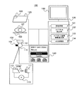
- FIG. 1A and FIG. 1B are diagrams showing an example of a schematic configuration of a radiation imaging apparatus 100 according to a first embodiment of the present invention.
- the radiation imaging apparatus 100 is an apparatus for imaging an imaging target ST using radiation 101. As shown in FIG. 1A, the radiation imaging apparatus 100 includes a radiation generation unit 110, a radiation detection unit 120, a processing / control unit 130, an operation unit 140, a display unit 150, a measuring unit 160, a radiation filter 102, a gantry 103, and , And a thermometer 104.
- the radiation generation unit 110 is a device that generates the radiation 101 with respect to the imaging target ST, and in the present embodiment, is a radiation tube.
- the radiation generation unit 110 is a radiation tube
- the present invention is not limited to this embodiment, and the radiation generation unit 110 may be added to the radiation tube as well.
- the form which comprised the components of these is also applicable to this invention.
- the radiation tube which is the radiation generating unit 110 includes a cathode 111 for generating thermal electrons, an anode 112 as a target, and a voltmeter 113 for measuring the voltage of the cathode 111 and the anode 112. It is included.
- a voltmeter 113 for measuring the voltage of the cathode 111 and the anode 112. It is included.
- the tube voltage a tube voltage corresponding to the low energy radiation 101 (first tube voltage V 1 shown in FIG. 3B) and a tube voltage corresponding to the high energy radiation 101 (second tube voltage shown in FIG. 3B Two tube voltages of V 2 ) are set.
- the radiation 101 emitted from the radiation generation unit 110 is incident on the imaging target ST via the radiation filter 102 and the gantry 103 on which the imaging target ST is placed.
- the gantry 103 is configured of a member that transmits the radiation 101.
- the radiation detection unit 120 is disposed at a position facing the radiation generation unit 110 with the imaging object ST interposed therebetween, and the radiation 101 generated by the radiation generation unit 110 (preferably, the radiation transmitted through the imaging object ST) 101) detecting device. Specifically, the radiation detection unit 120 detects the incident radiation 101 as an image signal which is an electrical signal.
- the pre-processing unit 131 performs pre-processing such as offset correction processing, gain correction, and defect correction on the image signal generated by the detection processing of the radiation detection unit 120.
- the spectrum calculation unit 132 calculates the spectrum of the radiation 101 based on the transient response characteristic of the radiation generation unit 110. This spectrum shows, for example, the relationship between energy and radiation intensity. The spectrum may indicate the relationship between energy and the number of photons or radiation intensity.
- the AEC processing unit 134 performs processing to determine the pulse width and the like of the radiation 101 actually irradiated from the radiation generation unit 110.
- the pulse width of the radiation 101 is determined by comparing the pulse width of the radiation 101 set by the operation of the operation unit 140 with the pulse width of the radiation 101 calculated from, for example, the pixel values of the image described above.
- the AEC processing unit 134 performs processing of determining the sample hold timing and the like according to the determined pulse width of the radiation 101.
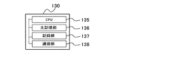
- FIG. 1B is a diagram illustrating an example of a hardware configuration of the processing and control unit 130 (for example, a computer) illustrated in FIG. 1A.
- the processing / control unit 130 includes hardware configurations of a central processing unit (CPU) 135, a main storage unit 136, a recording unit 137, and a communication unit 138.
- the communication unit 138 is, for example, a communication unit such as a LAN (Local Area Network) or sRIO (Serial Rapid Input / Output (registered trademark)).
- Equation (1) E is energy
- N (E) is the spectrum of radiation 101
- ⁇ 1 (E) is the linear attenuation coefficient of substance 1
- ⁇ 2 (E) is the linear attenuation coefficient of substance 2
- d 2 is the thickness of substance 2.
- the unknown variables in equation (1) are thickness d 1 and thickness d 2 . Since two independent equations can be generated by taking radiation 101 of two different energies and substituting this into equation (1), the thickness d 1 can be obtained by solving the two independent equations. And the thickness d 2 can be determined.
- spectral spatial information is the spatial distribution of effective atomic number and area density.
- the spatial distribution of the effective atomic number and the surface density can be expressed as the following equation (2).
- Equation (2) E is energy
- N (E) is the spectrum of radiation 101
- ⁇ (Z eff , E) is the mass attenuation coefficient at effective atomic number Z eff and energy E
- D eff is the effective areal density is there.
- the unknown variables in equation (2) are the effective atomic number Z eff and the effective area density D eff . Therefore, as in the case of obtaining the spatial distribution of thickness for each substance, two independent equations can be generated by imaging with radiation 101 of two different energies and substituting this in equation (2) From the above, the values of the effective atomic number Z eff and the effective area density D eff can be obtained by solving the two independent equations.
- the pixel 121 shown in FIG. 2 generates an image signal according to the irradiation of the radiation 101.
- the pixel 121 includes a photodiode 201, switches 202, 205 and 206, capacitors 203 and 204, a source follower circuit 207, a constant current source 208, sample and hold circuits 209, 210 and 211, and output amplifiers 212, 213 and 214.
- a phosphor (not shown) that converts the radiation 101 into light is provided on the side where the radiation 101 is incident.
- the photodiode 201 is a photoelectric conversion unit that converts light from a phosphor (not shown) into a charge, which is an electrical signal.
- the switch 202 is a switch for resetting the charge of the pixel 121.
- the capacitors 203 and 204 are capacitors for changing the sensitivity of the pixel 121.
- the switches 205 and 206 are switches for selecting the presence or absence of the sensitivity change of the pixel 121.
- the source follower circuit 207 is a circuit for reading the voltage value of the pixel 121.
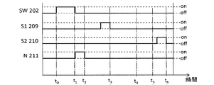
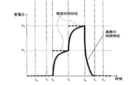
- FIG. 3A and 3B are diagrams showing an example of an operation method of the radiation detection unit 120 shown in FIG. 1A. Specifically, FIG. 3A shows a timing chart showing an example of an operation method of the pixel 121 shown in FIG. 2, and FIG. 3B shows a tube relating to a tube voltage change of the radiation generating unit 110 corresponding to the timing chart shown in FIG. An example of a voltage waveform is shown.
- the radiation generating unit 110 a control for generating a high energy radiation 101 corresponding to the second tube voltage V 2 shown in FIG. 3B I do.
- the tube voltage waveform shown in FIG. 3B greet the maximum value at time t 4 (the pulse width to be set, is often set as the difference between time t 4 and time t 2).
- processing and control unit 130 terminates the irradiation of the radiation 101.
- the processing / control unit 130 subtracts the value of the noise N accumulated in the sample and hold circuit 209 indicated by S1_209 to obtain the value of S1-N, and the noise N accumulated in the sample and hold circuit 210 indicated by S2_210. Subtract the value of to obtain the value of S2-N. Although the charge derived from both the low energy radiation 101 and the high energy radiation 101 is accumulated in the value of S2-N, the value of S2-N is further subtracted by the value of S1-N. in, it is possible to take out only the accumulated charge between time t 3 of the time t 5.
- the time characteristics of the first tube voltage V 1 and a second tube voltage V 2 is the transient response characteristics of the radiation tube is a radiation generating unit 110, until achieving the tube voltage set Require a finite amount of time (the “actual time characteristics” shown in FIG. 3B).
- This causes the spectral shape of the radiation 101 which is actually measured will those very different to the value expected from the first tube voltage V 1 and a second tube voltage V 2.
- the shape of the spectrum expected at a certain tube voltage is calculated as the tube voltage is constant with respect to time, and the tube voltage has a response characteristic as shown in "ideal time characteristics" in FIG. 3B. If so, the spectrum is accurately calculated.
- FIG. 4 is a flowchart showing an example of the processing procedure in the operation method of the radiation imaging apparatus 100 according to the first embodiment of the present invention.
- the processing / control unit 130 changes the mode of the radiation tube that is the radiation detection unit 120.
- the “mode” of the radiation detection unit 120 includes the tube voltage (for example, specified by kV (kilovolt)) by the operator, the tube current (for example, specified by mA (milliampere)), and the pulse width of the radiation 101 (for example, ms) (Specified in milliseconds), position change of radiation filter 102 and gantry 103 and fixing jig, change of imaging site (as mentioned above, tube voltage and tube current of the radiation tube corresponding to designation of imaging site, radiation)
- the pulse width of the radiation 101 and the arrangement of the radiation filter 102 and the gantry 103 are set), and the change of the pulse width of the radiation 101 by the AEC processing unit 134 is included.
- the “state change” of the radiation imaging apparatus 100 includes the temperature of the radiation tube that is the radiation generation unit 110 and a heat unit, and for example, the threshold of the temperature of the radiation tube monitored by the thermometer 104 Or when the heat unit of the radiation tube exceeds a certain threshold. Then, when detecting the mode transition or the state change, the processing / control unit 130 acquires information on the detected mode transition or the state change, and uses the information in the calculation processing of step S403 or step S404 later. At this time, the processing / control unit 130 simultaneously acquires information on a spectrum that does not change with time, for example, information of the radiation generation unit 110 (information such as specific filtration of the anode 112 serving as the target and the radiation tube).
- step S403 the spectrum calculation unit 132 converts the spectrum of the radiation 101 based on the tube voltage waveform of the radiation generation unit 110 acquired in step S402.
- step S403 the spectrum ((E) of the radiation 101 is expressed by the following equations (3) and (4).
- a i (E) is a coefficient determined by measurement of the spectrum
- V is a set tube voltage of the radiation tube (V i represents V to the power of i).
- “Otherwise” refers to a region other than the definition defined above (in the case of the equations (3) and (4), a region other than E ⁇ kV).
- the tube voltage waveform obtained in step S402 is V (t)
- the spectrum at time t is expressed by the following equations (5) and (6).
- the low energy spectra of radiation 101 corresponding to the first tube voltages V 1 is expressed by the following equation (7).
- t 2 the first tube voltage V 1 of the irradiation start time
- t 3 is the first pipe irradiation end time of voltages V 1 (see FIG. 3B).
- t 3 is the radiation irradiation start time of the second tube voltage V 2
- t 5 is the radiation end time of the second tube voltage V 2 (see FIG. 3B).
- the spectrum calculation unit 132 can determine the spectrum from the sample hold timing.
- the time t3 and the time t5 are changed by the pulse width of the radiation 101 set by the operator or the pulse width calculated by the AEC processing unit 134. Therefore, when these changes are made, the spectrum calculation unit 132 redetermines the spectrum based on the changed pulse width. Moreover, you may normalize (7) Formula and (8) Formula by each integral range etc. as needed.
- the spectrum calculation unit 132 further performs the inherent filtration of the radiation tube, the presence or absence of the radiation filter 102, the presence or absence of the gantry 103 (position information such as angle, etc.), and the radiation detection unit 120. In consideration of various factors that determine the spectrum, such as the front cover, the process of appropriately correcting the calculated spectrum is also performed. Specifically, the spectrum calculation unit 132, for example, determines the amount of attenuation per photon number when transmitting through each material from the thickness or energy dependent attenuation coefficient for each material in the radiation detection unit 120 ) And multiply it to correct the spectrum.
- step S404 the spectral space information calculating unit 133 calculates spectral space information using the spectrum of the radiation 101 calculated in step S403.
- the spectral space information calculated here include, as described above, the spatial distribution of thickness for each substance, the spatial distribution of effective atomic number and surface density, and the like.
- the first acquisition example of the tube voltage waveform of the radiation generation unit 110 actually uses the measuring apparatus such as the voltmeter 113 provided in the radiation imaging apparatus 100 to actually measure the transient response characteristics of the radiation tube which is the radiation generation unit 110. It is an aspect to measure.
- FIG. 5 is a diagram showing an example of a functional configuration of the spectrum calculation unit 132 according to the first acquisition example of the tube voltage waveform of the radiation generation unit 110 shown in FIG. 1A in the first embodiment of the present invention.
- the spectrum calculation unit 132 shown in FIG. 5 is referred to as “spectrum calculation unit 132-11”.
- the spectrum calculation unit 132-11 shown in FIG. 5 is configured to have respective functional configurations of a waveform acquisition unit 510, a tube voltage derivation unit 520, and a spectrum conversion unit 530. Further, the tube voltage deriving unit 520 includes a tube information storage unit 521 and a waveform processing unit 522.
- the waveform acquisition unit 510 acquires a tube voltage waveform of the radiation generation unit 110 from, for example, a voltmeter 113 provided in the radiation imaging apparatus 100.
- the waveform acquisition part 510 can also take the form which calculates and acquires the tube voltage waveform of the radiation generation part 110 based on the information of the dosimeter comprised to the measuring device 160. FIG.
- the tube voltage deriving unit 520 generates the voltage waveform of the radiation generating unit 110 based on the transient response characteristic of the radiation generating unit 110 stored in the tube information storage unit 521 and the voltage waveform acquired by the waveform acquiring unit 510.
- the tube information storage unit 521 stores information on the transient response characteristic of the radiation generation unit 110.
- the waveform processing unit 522 processes the voltage waveform acquired by the waveform acquisition unit 510 using the transient response characteristic of the radiation generation unit 110 stored in the tube information storage unit 521, and generates the voltage waveform of the radiation generation unit 110. To derive.
- the spectrum conversion unit 530 converts the spectrum of the radiation 101 based on the voltage waveform of the radiation generation unit 110 derived by the tube voltage derivation unit 520.
- FIG. 6 is a diagram showing an example of a functional configuration of the waveform processing unit 522 shown in FIG. As shown in FIG. 6, the waveform processing unit 522 shown in FIG. 5 includes a smoothing unit 610 and a waveform averaging unit 620.
- the smoothing unit 610 performs a process of smoothing the tube voltage waveform (described as “input tube voltage waveform” in FIG. 6) acquired by the waveform acquisition unit 510. Specifically, the smoothing unit 610 performs the smoothing process for each pulse of the radiation 101 (for each frame in the acquired radiation image).
- a method of smoothing by the smoothing unit 610 for example, polynomial-exponential function fitting using a moving average or a least squares method can be mentioned.
- a tube voltage waveform obtained by the waveform obtaining unit 510 a first tube voltage V 1 of the area (area 1), the second tube voltage V 2 of the region (region 2), and the region of wave tail It is possible to divide into (region 3) and perform fitting. Also, for example, in the derivation of the moving average, processing is performed so as not to include other regions in the derivation of the moving average. Also, for example, when performing polynomial fitting, different coefficients are used in each region.
- the waveform averaging unit 620 performs a process of averaging the plurality of tube voltage waveforms processed by the smoothing unit 610 with respect to the plurality of tube voltage waveforms acquired in time series in the waveform acquisition unit 510. Then, the waveform averaging unit 620 outputs a tube voltage waveform (described as “output tube voltage waveform” in FIG. 6) obtained by the averaging process. Specifically, the waveform averaging unit 620 performs the averaging process between a plurality of pulses of the radiation 101 (a plurality of frames in the acquired radiation image). That is, the waveform averaging unit 620 performs time-direction averaging processing on the plurality of tube voltage waveforms processed by the smoothing unit 610. This averaging process in the time direction can be performed recursively, for example, using the following equation (9).
- ⁇ is a coefficient.
- the tube voltage waveform (described as “output tube voltage waveform” in FIG. 6) obtained by the averaging process of the waveform averaging unit 620 is stored in the previous frame waveform storage unit 621, and the output tube voltage waveform of the next frame is Used to calculate. At this time, information of several past frames may be simply averaged.
- an appropriate tube voltage waveform can be obtained by setting an appropriate initial value even when the number of pulses of the radiation 101 is small.
- the initial value at this time is switched at each mode transition, and is stored in the previous frame waveform storage unit 621 before the first radiation irradiation is started.
- a tube voltage waveform to be input that is, a waveform when the impulse response is assumed to be a delta function
- a step function as shown in the following equation (10) is used.
- Equation (10) is a state in which there is no transient response of the radiation tube which is the radiation generation unit 110. By repeating the measurement, the transient response characteristic as shown in FIG. 3B can be gradually approached by the effect of the recursive filter, and the transient response of the radiation tube can be obtained.
- the tube voltage waveform before the mode transition may be used as the initial value as it is. Further, as an initial value, a method of storing the assumed tube voltage waveform in the tube information storage unit 521 in advance can be used. Moreover, when calculating the tube voltage waveform assumed as an initial value, you may use the 2nd acquisition example of the tube voltage waveform mentioned later, the 3rd acquisition example, and the 4th acquisition example mentioned later (this acquisition example is a calculated value. The accuracy of the tube voltage waveform is improved by using it together with the first acquisition example of the tube voltage waveform determined from the actual measurement value).
- FIG. 7 is a flow chart showing an example of the processing procedure of the waveform processing unit 522 shown in FIG.
- step S701 the waveform averaging unit 620 stores the initial value of the tube voltage waveform described above in the previous frame waveform storage unit 621.
- step S702 the smoothing unit 610 acquires a tube voltage waveform (described as “input tube voltage waveform” in FIG. 6) from the waveform acquisition unit 510.
- step S703 the smoothing unit 610 performs a process of smoothing the tube voltage waveform acquired in step S702 for each pulse of the radiation 101 (one frame in the acquired radiation image).
- step S704 the waveform averaging unit 620 performs the plurality of tube voltage waveforms processed by the smoothing unit 610 between a plurality of pulses of the radiation 101 (a plurality of frames in the acquired radiation image). Perform averaging processing.
- the waveform averaging unit 620 recursively performs this averaging process.
- step S705 the waveform averaging unit 620 outputs a tube voltage waveform (described as “output tube voltage waveform” in FIG. 6) obtained by the averaging process. Then, when the process of step S705 ends, the process of the flowchart illustrated in FIG. 7 ends.
- the second acquisition example of the tube voltage waveform of the radiation generation unit 110 is an aspect in which tube voltage measurement results under various imaging conditions are held in advance, and the tube voltage waveform of the set imaging conditions is determined by interpolation and extrapolation. .
- FIG. 8 is a diagram showing an example of a functional configuration of the spectrum calculation unit 132 according to a second example of acquisition of the tube voltage waveform of the radiation generation unit 110 shown in FIG. 1A in the first embodiment of the present invention.
- the spectrum calculation unit 132 shown in FIG. 8 is referred to as “spectrum calculation unit 132-12”.
- the same components as those shown in FIG. 5 are denoted by the same reference numerals, and the detailed description thereof will be omitted.
- the spectrum calculation unit 132-12 shown in FIG. 8 is configured to have respective functional configurations of an imaging condition acquisition unit 810, a tube voltage derivation unit 520, and a spectrum conversion unit 530.
- the tube voltage deriving unit 520 is configured to include a tube information storage unit 521 and an interpolation / supplement 523.
- the imaging condition acquisition unit 810 acquires imaging conditions relating to radiation imaging of the radiation generation unit 110.
- the tube voltage deriving unit 520 generates a voltage waveform of the radiation generating unit 110 based on the transient response characteristic of the radiation generating unit 110 stored in the tube information storage unit 521 and the imaging condition acquired by the imaging condition acquiring unit 810. Derive Specifically, the tube information storage unit 521 stores information on the transient response characteristic of the radiation generation unit 110. In the second acquisition example of the tube voltage waveform, the tube information storage unit 521 stores the tube voltage waveform acquired in advance. The tube voltage waveform is acquired by using the voltmeter 113 at the time of calibration, or acquired by using a dosimeter provided in the measuring device 160.
- the voltmeter 113 and the dosimeter may be removable.
- Interpolation / extrapolation 523 interpolates and extrapolates based on the imaging condition acquired by imaging condition acquisition unit 810 using the transient response characteristic of radiation generation unit 110 stored in tube information storage unit 521, The tube voltage waveform of the radiation generation unit 110 is derived.
- the spectrum conversion unit 530 converts the spectrum of the radiation 101 based on the voltage waveform of the radiation generation unit 110 derived by the tube voltage derivation unit 520.
- the tube voltage set by the operator at the time of mode transition is referred to as the set tube voltage
- the tube voltage acquired using the voltmeter 113 or the dosimeter is referred to as the observation tube voltage
- the tube current set by the operator is called a set tube current
- the pulse width set by the operator is called a set pulse width.
- the tube voltage of the tube voltage waveform means the waveform of the observation tube voltage.
- the observation tube voltage waveform is stored in association with the acquisition condition (calibration condition) at the time of calibration.
- Items of calibration conditions include a set tube voltage, a set tube current, a set pulse width and the like.
- the interpolation / extrapolation 523 derives the observation tube voltage waveform under the imaging conditions set by interpolating and extrapolating the observation tube voltage waveform acquired in advance based on the imaging conditions set at the time of mode transition. Do.
- the data structure of the tube information storage unit 521 shown in FIG. 8 and the interpolation method will be described below.
- the information of the observation tube voltage waveform is organized by a tree structure as shown in a tube information storage unit 521 shown in FIG.
- classification regarding the set tube voltage is performed in the first hierarchy
- classification regarding the set pulse width is performed in the second hierarchy
- classification regarding the setting tube current is performed in the third hierarchy.
- the interpolation / supplement 523 first performs interpolation on the set tube current of the third hierarchy, then performs interpolation on the set pulse width of the second hierarchy, and finally performs interpolation on the set tube voltage of the first hierarchy.
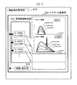
- FIG. 9 is a flowchart showing an example of the processing procedure of the imaging condition acquisition unit 810 and the tube voltage derivation unit 520 shown in FIG. 10A to 10C are diagrams for explaining the processing of the interpolation / supplement 523 shown in FIG.
- the imaging condition acquisition unit 810 acquires imaging conditions set at the time of mode transition.
- the imaging conditions acquired here are the set tube voltage, the set tube current, and the set pulse width in the second example of obtaining the tube voltage waveform, but the present invention is not limited to this form.
- information on the temperature of the radiation tube or the heat unit may be acquired as the imaging condition.
- a temperature or heat unit interpolation process is inserted between step S901 and step S902.
- step S902 the interpolation / extrapolation 523 calculates the observation tube voltage waveform in the setting tube current of the third hierarchy described above by interpolation / extrapolation.
- An image of the process of this step S902 (specifically, the interpolation process of the interpolation / supplement 523) is shown in FIG. 10A.
- the interpolation / supplement 523 obtains the relationship between the tube current shown in the display area 1012 and the observation tube voltage for each time of the observation tube voltage waveform shown in the display area 1011 by interpolation, and each time of the set tube current Derive the value of the observation tube voltage at Interpolation in this case uses a general method such as polynomial fitting by the least square method, for example.
- step S903 the interpolation / supplement 523 determines whether or not the calculation of the observation tube voltage waveform in all the set pulse widths is completed. As a result of this determination, if the calculation of the observation tube voltage waveform at all the set pulse widths has not been completed (S903 / N), the process returns to step S902, and the process of step S902 is performed again.
- step S903 when the calculation of the observation tube voltage waveform in all the set pulse widths is completed (S903 / Y), the process proceeds to step S904.
- step S904 the interpolation / supplementation 523 determines whether the calculation of the observation tube voltage waveform at all set tube voltages has been completed. As a result of this determination, when the calculation of the observation tube voltage waveform at all the set tube voltages has not been completed (S904 / N), the process returns to step S902, and the processes after step S902 are performed again.
- step S904 when the calculation of the observation tube voltage waveform at all the set tube voltages is completed (S904 / Y), the process proceeds to step S905.
- step S 905 the interpolation / extrapolation 523 calculates the observation tube voltage waveform in the setting pulse width of the second layer described above by interpolation / extrapolation.
- An image of the process of this step S 905 (specifically, the interpolation process of the interpolation / supplement 523) is shown in FIG. 10B.
- step S906 the interpolation / supplement 523 determines whether or not calculation of the observation tube voltage waveform at all set tube voltages has been completed. As a result of this determination, when the calculation of the observation tube voltage waveform at all the set tube voltages has not been completed (S906 / N), the process returns to step S905, and the process of step S905 is performed again.
- step S906 when the calculation of the observation tube voltage waveform at all the set tube voltages is completed (S906 / Y), the process proceeds to step S907.
- step S 907 the interpolation / extrapolation 523 calculates the observation tube voltage waveform at the set tube voltage of the first layer described above by interpolation / extrapolation.
- An image of the process of this step S 907 (specifically, the interpolation process of the interpolation / supplement 523) is shown in FIG. 10C.
- the interpolation / supplement 523 sets the set tube voltage shown in the display area 1032 and the observation tube for each time of the observation tube voltage waveform shown in the display area 1031 (including the observation tube voltage waveform shown in the display area 1033).
- the relationship of voltage is determined by interpolation, and the value of the observation tube voltage at each time of the set tube voltage is derived. Then, when the process of step S 907 ends, the process of the flowchart illustrated in FIG. 9 ends.
- the interpolation / supplement 523 When importance is placed on the accuracy of interpolation by the interpolation / supplement 523, it is desirable to perform processing in the case of combinations of all set tube voltages and set tube currents as in the example shown in FIG. If not, some data interpolation can be omitted.
- the tube voltage waveform used for the interpolation may be only the four interpolation conditions [1] to [4] of Table 1, which are tube voltage waveforms of calibration conditions adjacent to the imaging conditions.
- calibration is performed before radiation imaging, but may be performed after radiation imaging. Generally, it is acquired other than at the time of radiation irradiation for image formation.
- the third acquisition example of the tube voltage waveform is that the radiation tube, which is the radiation generation unit 110, is a linear and time-invariant (LTI) system, and radiation is used instead of holding the tube voltage waveform. This is an aspect of holding a tube impulse response and using it to acquire a tube voltage waveform.
- LTI linear and time-invariant
- FIG. 11 is a diagram showing an example of a functional configuration of a spectrum calculation unit 132 according to a third example of obtaining a tube voltage waveform of the radiation generation unit 110 shown in FIG. 1A in the first embodiment of the present invention.
- the spectrum calculation unit 132 shown in FIG. 11 is referred to as “spectrum calculation unit 132-13”.
- the same components as those shown in FIGS. 5 and 8 are designated by the same reference numerals and their detailed description will be omitted.
- the spectrum calculation unit 132-13 shown in FIG. 11 is configured to have respective functional configurations of an imaging condition acquisition unit 810, a tube voltage derivation unit 520, and a spectrum conversion unit 530. Further, the tube voltage deriving unit 520 includes a tube information storage unit 521, a waveform processing unit 522, an interpolation / extrapolation 523, a convolution calculation unit 524, and an impulse response calculation unit 525.
- the tube information storage unit 521 stores information on an impulse response characteristic as a transient response characteristic of the radiation generation unit 110. Specifically, in the third acquisition example of the tube voltage waveform, the tube information storage unit 521 stores the impulse response in association with the impulse response acquisition condition (calibration condition) at the time of calibration. At this time, as the items of the calibration conditions, a set tube voltage, a set tube current, a set pulse width and the like can be mentioned. Here, in the example shown in FIG. 11, the impulse response of each tube current is stored in the tube information storage unit 521.
- the convolution calculation unit 524 performs convolution processing on the impulse response.
- the impulse response calculation unit 525 performs calculation regarding the impulse response.
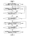
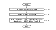
- FIG. 12 is a flowchart showing an example of the processing procedure of the tube voltage deriving unit 520 shown in FIG.
- the impulse response calculation unit 525 calculates an impulse response g (t).
- the information on the transition mode and the change state acquired by the imaging condition acquisition unit 810 is used.
- the impulse response includes, for example, tube current dependency, temperature dependency of the radiation tube, and heat unit dependency, it is necessary to appropriately calculate the impulse response corresponding to the information acquired by the imaging condition acquisition unit 810 is there.
- a calculation method when the tube current of the radiation tube which is the radiation generation unit 110 is changed will be described below using FIG.
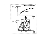
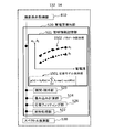
- FIG. 13 is a diagram showing an example of calculation of an impulse response by the impulse response calculation unit 525 shown in FIG.
- the tube information storage unit 521 holds a plurality of measurement results of the impulse response of the radiation tube linked to the tube current.
- the impulse response in the set tube current shown in the display region 1302 is obtained by interpolating the measurement results of the impulse response for each time by the interpolation / extrapolation 523 and the impulse response calculation unit 525. Or extrapolate and ask.
- the display area 1301 is an arrangement of impulse responses of a plurality of measured tube currents in the relationship of time, tube current, and impulse response.
- the impulse response is obtained in advance as a calibration.
- the calculation of the impulse response by the impulse response calculation unit 525 can be performed in the same manner for the temperature of the radiation tube and the heat unit. That is, in this case, the temperature of the radiation tube and the heat unit may be combined with the impulse response of the radiation tube, stored in the tube information storage unit 521, and interpolated similarly to the tube current.
- the tube voltage derivation unit 520 obtains a tube input waveform f (t) related to the tube voltage waveform of the radiation generation unit 110.
- the tube voltage waveform at this time may be, for example, the step function described above in the equation (8), but this embodiment is not limited to this.
- the maximum advantage is that the spectrum of the radiation 101 can be determined for an arbitrary waveform (for example, a triangular wave or the like) other than the step function described in the equation (10).
- step S1203 the convolution calculation unit 524 uses the impulse response g (t) acquired in step S1201 and the tube input waveform f (t) acquired in step S1202 to obtain the tube voltage output waveform h Calculate t) by convolution.
- the tube voltage output h (t) is calculated by the following equation (11).
- the spectrum of the radiation 101 is calculated according to the process of the flowchart shown in FIG. 4, for example.
- FIG. 14 is a flowchart showing an example of a processing procedure in a method of calibrating an impulse response according to a third example of acquisition of the tube voltage waveform of the radiation generation unit 110 shown in FIG. 1A in the first embodiment of the present invention.
- the calibration of this example can be obtained, for example, by the impulse response calculation unit 525 by performing Laplace transform / inverse transform of the step response.
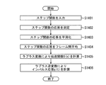
- step S1401 for example, the impulse response calculation unit 525 inputs a step function.
- a step function As an example of the function input here, there can be mentioned, for example, a single step function shown in the following equation (12).
- step S1402 the impulse response calculation unit 525 measures the response (tube voltage waveform) of the step function input in step S1401.
- the measurement is performed using, for example, a dosimeter provided in the voltmeter 113 or the measuring device 160.
- the voltmeter 113 or the dosimeter may be removed.
- step S1403 the waveform processing unit 522 (smoothing unit 610) smoothes the response of the step function obtained in step S1402 within one pulse.
- step S1404 the waveform processing unit 522 (waveform averaging unit 620) performs processing for averaging the results obtained in step S1403 between frames.
- step S1405 the impulse response calculation unit 525 performs a Laplace transform on the response of the step function processed in steps S1403 and S1404 to calculate a transfer function.
- the Laplace transform of the input (calculated numerically from the input) is F (s)
- the transfer function is G (s)
- the Laplace transform of the output is H (s)
- step S1406 the impulse response calculation unit 525 performs inverse Laplace transform on the transfer function G (s) obtained in step S1405 to obtain an impulse response g (t). Then, when the process of step S1406 ends, the process of the flowchart illustrated in FIG. 14 ends.
- the step function is input and the impulse response of the radiation tube is obtained from the response, but instead the impulse function is input and Fourier transform / inverse conversion is performed Direct impulse response may be determined.
- confirmation of linear time invariance of the radiation tube is obtained by obtaining the impulse response by the above method under certain conditions, fixing the tube current, and changing the set tube voltage and pulse width in various ways, The tube voltage waveforms calculated from the determined impulse responses may be compared. If linear time invariance does not hold accurately, it is necessary to correct the impulse response appropriately according to the input value.
- the transfer function is obtained using the Laplace transform, but may be obtained using a similar method such as z-transform.
- parameter dependence of the impulse response eg, tube current dependence, temperature dependence of radiation tube, heat unit dependence, etc.
- the process of interpolation as shown in FIG. 13 may be omitted. it can.
- the calibration is performed before radiation imaging, it may be performed after radiation imaging. Generally, it is acquired other than at the time of radiation irradiation for image formation.
- the impulse response is determined, and the output waveform is derived by convoluting it with the input waveform.
- the impulse response is modeled by a known function. This can reduce the amount of calculation significantly.
- FIG. 15 is a diagram showing an example of a functional configuration of a spectrum calculation unit 132 according to a fourth example of obtaining a tube voltage waveform of the radiation generation unit 110 shown in FIG. 1A in the first embodiment of the present invention.
- the spectrum calculation unit 132 shown in FIG. 15 is referred to as “spectrum calculation unit 132-14”.
- the same components as those shown in FIGS. 5, 8 and 11 are designated by the same reference numerals and their detailed description will be omitted.
- the spectrum calculation unit 132-14 shown in FIG. 15 is configured to have respective functional configurations of an imaging condition acquisition unit 810, a tube voltage derivation unit 520, and a spectrum conversion unit 530. Further, the tube voltage deriving unit 520 includes a tube information storage unit 521, a waveform processing unit 522, an interpolation / extrapolation 523, a convolution calculation unit 524, and a response fitting unit 526.
- the tube information storage unit 521 includes a response model holding unit 1501 and a parameter holding unit 1502.
- the response fitting unit 526 performs fitting processing related to the response model held by the response model holding unit 1501.
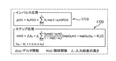
- the response model relating to the impulse response of the radiation tube held by the response model holding unit 1501 is, for example, an exponent having a delta function and (a reciprocal of) a plurality of time constants, as shown in the following equation (15) It can be expressed by the sum of functions.
- FIG. 17A is a flowchart showing an example of a processing procedure in a method of calibrating an impulse response according to a fourth example of obtaining a tube voltage waveform of the radiation generation unit 110 shown in FIG. 1A in the first embodiment of the present invention.
- FIG. 17B describes Equation 1710 related to the impulse response and Equation 1720 related to the step response.
- the same step number is attached
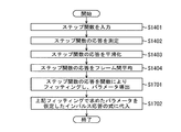
- step S1401 of FIG. 17A for example, the response fitting unit 526 inputs a step function.
- step S1402 of FIG. 17A the response fitting unit 526 measures the response (tube voltage waveform) of the step function input in step S1401 of FIG. 17A.
- step S1403 of FIG. 17A the waveform processing unit 522 (smoothing unit 610) smoothes the response of the step function obtained in step S1402 of FIG. 17A within one pulse.
- step S1404 in FIG. 17A the waveform processing unit 522 (waveform averaging unit 620) performs a process of averaging the results obtained in step S1403 in FIG. 17A between frames.
- step S1701 of FIG. 17A the response fitting unit 526 fits the response of the step function processed in steps S1403 and S1404 with an analysis solution of the function to derive the above-described parameters.
- step S1702 of FIG. 17A the response fitting unit 526 substitutes the parameter derived in step S1701 into an assumed impulse response equation to obtain an impulse response.
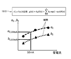
- the impulse response has, for example, tube current dependency, temperature dependency of the radiation tube, and heat unit dependency, so it is necessary to derive an impulse response corresponding to those values.
- interpolation and extrapolation are performed by the interpolation and extrapolation 523 on the parameters.
- the response fitting unit 526 determines, for example, a parameter of impulse response at each tube current, and the horizontal axis shown in FIG. 16 fits the tube current and the vertical axis fits the parameter graph. Then, the response fitting unit 526 may input the parameter input at the time of the next mode transition to the fitting function, and use the output value as the parameter to use.
- the calculation of the impulse response can be performed in the same manner with respect to the temperature of the radiation tube and the heat unit, as in the case of the third acquisition example of the tube voltage waveform described above.
- step function input in step S1401 of FIG. 17A is the following equation (16)
- the step response is analytically determined as in equation (17) below: be able to.
- step S1701 in FIG. 17A the response fitting unit 526 fits equation (17) to the data of the time average of the response of the step function obtained in step S1404.
- the fitting may be performed using a generally used method such as, for example, making the square of the difference between the time average of the response of the step function and the equation (17) minimum.
- the parameters b 0 , a 1 , b 1 are thereby determined.
- step S1702 of FIG. 17A the response fitting unit 526 can obtain an impulse response by substituting the determined parameter into the equation (15).
- the model used by the 4th example of acquisition of a tube voltage waveform is not limited to (15) Formula
- Another model can be used.
- it may be a model obtained by approximating an impulse response by an nth polynomial (in this case, the parameters become coefficients of the polynomial).
- the impulse response parameters can not necessarily be obtained only by fitting as in equation (17), and there may be cases where Laplace transformation, z transformation, or Fourier transformation is required.
- the model is not limited to that in real time, and may be assumed, for example, a frequency space after Fourier transform, a z space of z transform, and a s space after Laplace transform.
- the step function is input and the impulse response of the radiation tube is determined from the response. Instead, the impulse function is input and direct impulse response is performed by fitting the response. You may ask for
- the schematic configuration of the radiation imaging apparatus according to the second embodiment is the same as the schematic configuration of the radiation imaging apparatus 100 according to the first embodiment shown in FIG. 1A.
- the circuit configuration and operation method of the radiation detection unit 120 shown in FIG. 1A are also the same as the circuit configuration and operation method of the radiation detection unit 120 according to the first embodiment shown in FIG. 2 and FIGS. 3A and 3B. is there.
- the spectrum of the radiation 101 is calculated by obtaining the tube voltage waveform, but in the second embodiment, the spectrum of the radiation 101 is measured without obtaining the tube voltage waveform.
- the spectrum of the radiation 101 is directly detected by correlating the measured spectrum of the radiation 101 with the imaging conditions. In this case, the transient response of the radiation tube which is the radiation generation unit 110 is taken into consideration when measuring the spectrum of the radiation 101.
- FIG. 18 is a diagram showing a second embodiment of the present invention and showing an example of a functional configuration of the spectrum calculation unit 132 shown in FIG. 1A.
- the spectrum calculation unit 132 shown in FIG. 18 is referred to as “spectrum calculation unit 132-2”.
- the same components as those shown in FIGS. 5, 8, 11, and 15 are designated by the same reference numerals, and the detailed description thereof will be omitted.
- the spectrum calculation unit 132-2 shown in FIG. 18 is configured to have the functional configuration of the imaging condition acquisition unit 810 and the spectrum conversion unit 530. Further, the spectrum conversion unit 530 is a tube information storage unit 531 corresponding to the tube information storage unit 521 in the first embodiment, and an interpolation / extrapolation corresponding to the interpolation / extrapolation 523 in the first embodiment. 532 is included.
- the tube information storage unit 531 stores information on the transient response characteristic of the radiation tube which is the radiation generation unit 110. Specifically, the tube information storage unit 531 sets calibration conditions (a set tube voltage, a set tube current, a set pulse width, a temperature of a radiation tube, a heat unit of a radiation tube) as a transient response characteristic of the radiation generation unit 110. ) Is stored (the horizontal axis represents energy of one photon, and the vertical axis represents the number of photons). Spectrum in this case, the spectrum corresponding to the first tube voltage V 1 of the low-energy spectrum corresponding to the second tube voltage V 2 of high energy are stored.
- the tube voltage deriving unit 520 includes the tube information storage unit 521.
- the tube voltage deriving unit does not need to derive the tube voltage.
- the part 520 is not configured.
- the spectrum conversion unit 530 is provided with a tube information storage unit 531 corresponding to the tube information storage unit 521 in the first embodiment.
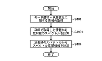
- FIG. 19 is a flow chart showing an example of the processing procedure of the spectrum calculation unit 132-2 shown in FIG.
- the same processes as the processes shown in FIG. 4 have the same step numbers, and the detailed description thereof will be omitted.
- the spectrum calculation unit 132-2 acquires information on the detected mode transition or state change when the mode transition or state change is detected.
- the spectrum calculation unit 132-2 calculates the spectrum of the radiation 101 based on the information acquired in step S401.
- the spectrum is not only a function of single photon energy but also a function of tube current and input pulse width.
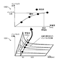
- the spectrum calculation unit 132-2 fixes the tube voltage, acquires data with a plurality of input pulse widths or tube currents, and acquires the acquired data in the pulse width of the x-axis as shown in the display area 2001 of FIG.
- the y-axis is arranged in a tube current, and the z-axis is arranged in a three-dimensional graph of the number of photons (measured values (black points) in the display area 2001 in FIG. 20).
- the spectrum calculation unit 132-2 calculates a function ⁇ (E: mA, ms) (where E is energy of one photon, mA is a tube current, and ms is a pulse width) which is a curved surface at these points. By fitting, the number of photons is determined for an arbitrary tube current and pulse width. Then, the spectrum calculation unit 132-2 holds the function ⁇ (E: mA, ms) for each energy E, as shown in the display area 2002 of FIG. The spectrum can be determined.
- ⁇ E: mA, ms
- the measured spectrum is acquired using the spectrometer with which the measuring device 160 was equipped.
- the acquired spectrum is stored in the tube information storage unit 531 in association with the first tube voltage V 1 , the second tube voltage V 2 , the tube current, and the pulse width.
- the second embodiment can calculate a transient response from information prepared in advance at the time of calibration. This is an effective means when it is difficult to measure information related to the spectrum of radiation 101 such as tube voltage.
- the calibration is performed before radiation imaging, it may be performed after radiation imaging. Generally, it is acquired other than at the time of radiation irradiation for image formation.
- the spectrum of radiation can be calculated with high accuracy.
- the present invention supplies a program that implements one or more functions of the above-described embodiments to a system or apparatus via a network or storage medium, and one or more processors in a computer of the system or apparatus read and execute the program. Can also be realized. It can also be implemented by a circuit (eg, an ASIC) that implements one or more functions.
- the program and a computer readable storage medium storing the program are included in the present invention.
- 100 radiation imaging apparatus, 101: radiation, 102: radiation filter, 103: mount, 104: thermometer, 110: radiation generation unit, 120: radiation detection unit, 130: processing / control unit, 131: pre-processing unit, 132 : Spectrum calculation unit, 133: Spectrum space information calculation unit, 134: AEC processing unit, 140: Operation unit, 150: Display unit, 160: Measuring instrument
Landscapes
- Health & Medical Sciences (AREA)
- Life Sciences & Earth Sciences (AREA)
- Engineering & Computer Science (AREA)
- Medical Informatics (AREA)
- General Health & Medical Sciences (AREA)
- Physics & Mathematics (AREA)
- Pathology (AREA)
- Heart & Thoracic Surgery (AREA)
- Public Health (AREA)
- Nuclear Medicine, Radiotherapy & Molecular Imaging (AREA)
- Optics & Photonics (AREA)
- Biophysics (AREA)
- Radiology & Medical Imaging (AREA)
- Biomedical Technology (AREA)
- Veterinary Medicine (AREA)
- Molecular Biology (AREA)
- Surgery (AREA)
- Animal Behavior & Ethology (AREA)
- High Energy & Nuclear Physics (AREA)
- Toxicology (AREA)
- Chemical & Material Sciences (AREA)
- Analytical Chemistry (AREA)
- Biochemistry (AREA)
- General Physics & Mathematics (AREA)
- Immunology (AREA)
- Computer Vision & Pattern Recognition (AREA)
- Mathematical Physics (AREA)
- Measurement Of Radiation (AREA)
- X-Ray Techniques (AREA)
- Apparatus For Radiation Diagnosis (AREA)
Priority Applications (1)
| Application Number | Priority Date | Filing Date | Title |
|---|---|---|---|
| US16/847,074 US20200245441A1 (en) | 2017-10-16 | 2020-04-13 | Radiation imaging apparatus, operation method therefor, and computer-readable medium |
Applications Claiming Priority (2)
| Application Number | Priority Date | Filing Date | Title |
|---|---|---|---|
| JP2017200574A JP2019072190A (ja) | 2017-10-16 | 2017-10-16 | 放射線撮影装置及びその動作方法、並びに、プログラム |
| JP2017-200574 | 2017-10-16 |
Related Child Applications (1)
| Application Number | Title | Priority Date | Filing Date |
|---|---|---|---|
| US16/847,074 Continuation US20200245441A1 (en) | 2017-10-16 | 2020-04-13 | Radiation imaging apparatus, operation method therefor, and computer-readable medium |
Publications (1)
| Publication Number | Publication Date |
|---|---|
| WO2019078079A1 true WO2019078079A1 (ja) | 2019-04-25 |
Family
ID=66173604
Family Applications (1)
| Application Number | Title | Priority Date | Filing Date |
|---|---|---|---|
| PCT/JP2018/037867 Ceased WO2019078079A1 (ja) | 2017-10-16 | 2018-10-11 | 放射線撮影装置及びその動作方法、並びに、プログラム |
Country Status (3)
| Country | Link |
|---|---|
| US (1) | US20200245441A1 (enExample) |
| JP (1) | JP2019072190A (enExample) |
| WO (1) | WO2019078079A1 (enExample) |
Families Citing this family (5)
| Publication number | Priority date | Publication date | Assignee | Title |
|---|---|---|---|---|
| JP7245001B2 (ja) | 2018-05-29 | 2023-03-23 | キヤノン株式会社 | 放射線撮像装置および撮像システム |
| JP7093233B2 (ja) | 2018-06-07 | 2022-06-29 | キヤノン株式会社 | 放射線撮影装置、放射線撮影方法およびプログラム |
| WO2020003744A1 (ja) | 2018-06-27 | 2020-01-02 | キヤノン株式会社 | 放射線撮影装置、放射線撮影方法およびプログラム |
| JP7397593B2 (ja) | 2019-07-23 | 2023-12-13 | キヤノン株式会社 | 放射線撮像装置、画像取得方法およびプログラム |
| JP7378245B2 (ja) | 2019-08-29 | 2023-11-13 | キヤノン株式会社 | 放射線検出装置、その制御方法及び放射線撮像システム |
Citations (1)
| Publication number | Priority date | Publication date | Assignee | Title |
|---|---|---|---|---|
| WO2008072175A1 (en) * | 2006-12-15 | 2008-06-19 | Koninklijke Philips Electronics N.V. | Spectrally resolving x-ray imaging device |
Family Cites Families (2)
| Publication number | Priority date | Publication date | Assignee | Title |
|---|---|---|---|---|
| JP6289223B2 (ja) * | 2013-04-04 | 2018-03-07 | キヤノンメディカルシステムズ株式会社 | X線コンピュータ断層撮影装置 |
| EP3384277B1 (en) * | 2015-12-03 | 2022-09-14 | Koninklijke Philips N.V. | Apparatus for determining an effective energy spectrum of an x-ray tube |
-
2017
- 2017-10-16 JP JP2017200574A patent/JP2019072190A/ja active Pending
-
2018
- 2018-10-11 WO PCT/JP2018/037867 patent/WO2019078079A1/ja not_active Ceased
-
2020
- 2020-04-13 US US16/847,074 patent/US20200245441A1/en not_active Abandoned
Patent Citations (1)
| Publication number | Priority date | Publication date | Assignee | Title |
|---|---|---|---|---|
| WO2008072175A1 (en) * | 2006-12-15 | 2008-06-19 | Koninklijke Philips Electronics N.V. | Spectrally resolving x-ray imaging device |
Non-Patent Citations (1)
| Title |
|---|
| BHAT ET AL.: "Diagnostic x-ray spectra: A comparison of spectra generated by different computational methods with a measured spectrum", MEDICAL PHYSICS, vol. 25, no. 1, January 1998 (1998-01-01), pages 114, XP012010298, DOI: doi:10.1118/1.598170 * |
Also Published As
| Publication number | Publication date |
|---|---|
| US20200245441A1 (en) | 2020-07-30 |
| JP2019072190A (ja) | 2019-05-16 |
Similar Documents
| Publication | Publication Date | Title |
|---|---|---|
| WO2019078079A1 (ja) | 放射線撮影装置及びその動作方法、並びに、プログラム | |
| JP7085043B2 (ja) | 画像処理装置、画像処理方法及びプログラム | |
| JP3903027B2 (ja) | 放射線画像処理方法及び装置並びにグリッドの選別方法及び装置 | |
| JP7054329B2 (ja) | 画像処理装置、画像処理方法及びプログラム | |
| JP2015204985A (ja) | X線エネルギースペクトル測定方法およびx線エネルギースペクトル測定装置およびx線ct装置 | |
| JP7000582B2 (ja) | 電荷共有キャリブレーション方法及びシステム | |
| EP3804623B1 (en) | Radiation imaging apparatus, radiation imaging method, and program | |
| EP3673805A1 (en) | Radiation imaging device and radiation imaging system | |
| JP2008502395A (ja) | 投影放射線撮影、特に乳房撮影における散乱放射線補正装置および方法 | |
| US10648930B2 (en) | Apparatus for determining an effective energy spectrum of an X-ray tube | |
| CN114828749B (zh) | 谱ct kv纹波检测和校正方法 | |
| JP2008229194A (ja) | X線画像診断装置 | |
| Kim et al. | Signal lag measurements based on temporal correlations | |
| JP2009142497A (ja) | X線診断装置 | |
| JP4746761B2 (ja) | 放射線画像処理装置、放射線画像処理方法、記憶媒体、及びプログラム | |
| JP3793039B2 (ja) | 画像処理方法、画像処理装置、放射線画像処理装置、画像処理システム及びプログラム | |
| KR101605896B1 (ko) | 컴퓨터 단층촬영 영상 처리 장치 및 방법 | |
| EP3661334B1 (en) | Apparatus for generating x-rays | |
| CN116458906B (zh) | 侧位图生成方法、装置、电子设备及存储介质 | |
| EP4199659A1 (en) | Apparatus for determining an effective spectrum of an x-ray tube and high voltage generator for spectral x-ray imaging | |
| Caeiros et al. | A differential high-resolution motorized multi-projection approach for an experimental Magnetic Induction Tomography prototype | |
| Tkadlecová et al. | Flat-Field based Characterization, Modeling and Simulation of Noise in a Digital X-ray Imaging System | |
| JP4393436B2 (ja) | 放射線画像処理装置、画像処理システム、放射線画像処理方法、記憶媒体及びプログラム | |
| JP2017148400A (ja) | 放射線撮影装置、放射線撮影システム、及びプログラム | |
| King | Digital image processing in radioisotope scanning |
Legal Events
| Date | Code | Title | Description |
|---|---|---|---|
| 121 | Ep: the epo has been informed by wipo that ep was designated in this application |
Ref document number: 18868298 Country of ref document: EP Kind code of ref document: A1 |
|
| NENP | Non-entry into the national phase |
Ref country code: DE |
|
| 122 | Ep: pct application non-entry in european phase |
Ref document number: 18868298 Country of ref document: EP Kind code of ref document: A1 |