EP3673805A1 - Radiation imaging device and radiation imaging system - Google Patents
Radiation imaging device and radiation imaging system Download PDFInfo
- Publication number
- EP3673805A1 EP3673805A1 EP18847549.5A EP18847549A EP3673805A1 EP 3673805 A1 EP3673805 A1 EP 3673805A1 EP 18847549 A EP18847549 A EP 18847549A EP 3673805 A1 EP3673805 A1 EP 3673805A1
- Authority
- EP
- European Patent Office
- Prior art keywords
- radiation
- image signal
- image
- imaging
- energy
- Prior art date
- Legal status (The legal status is an assumption and is not a legal conclusion. Google has not performed a legal analysis and makes no representation as to the accuracy of the status listed.)
- Withdrawn
Links
- 230000005855 radiation Effects 0.000 title claims abstract description 336
- 238000003384 imaging method Methods 0.000 title claims abstract description 218
- 238000006243 chemical reaction Methods 0.000 claims abstract description 42
- 238000012545 processing Methods 0.000 claims description 53
- 230000005540 biological transmission Effects 0.000 claims description 9
- 238000005070 sampling Methods 0.000 claims description 9
- 230000008859 change Effects 0.000 claims description 8
- 238000012935 Averaging Methods 0.000 claims description 7
- 230000014509 gene expression Effects 0.000 claims description 6
- 230000002123 temporal effect Effects 0.000 claims description 6
- 238000012937 correction Methods 0.000 claims description 4
- 230000003213 activating effect Effects 0.000 description 17
- 239000003990 capacitor Substances 0.000 description 16
- 238000000034 method Methods 0.000 description 15
- 230000003321 amplification Effects 0.000 description 11
- 210000000988 bone and bone Anatomy 0.000 description 11
- 238000003199 nucleic acid amplification method Methods 0.000 description 11
- 208000009989 Posterior Leukoencephalopathy Syndrome Diseases 0.000 description 10
- 238000009825 accumulation Methods 0.000 description 10
- 230000006870 function Effects 0.000 description 8
- 230000000630 rising effect Effects 0.000 description 7
- 230000035945 sensitivity Effects 0.000 description 7
- 210000004872 soft tissue Anatomy 0.000 description 6
- 238000011410 subtraction method Methods 0.000 description 4
- 230000007423 decrease Effects 0.000 description 3
- 238000010586 diagram Methods 0.000 description 3
- 239000002245 particle Substances 0.000 description 3
- 230000008569 process Effects 0.000 description 3
- 230000001629 suppression Effects 0.000 description 3
- 238000004458 analytical method Methods 0.000 description 2
- 238000003780 insertion Methods 0.000 description 2
- 230000037431 insertion Effects 0.000 description 2
- 239000000463 material Substances 0.000 description 2
- 230000000007 visual effect Effects 0.000 description 2
- 230000015572 biosynthetic process Effects 0.000 description 1
- JJWKPURADFRFRB-UHFFFAOYSA-N carbonyl sulfide Chemical compound O=C=S JJWKPURADFRFRB-UHFFFAOYSA-N 0.000 description 1
- 238000004891 communication Methods 0.000 description 1
- 238000010276 construction Methods 0.000 description 1
- 239000002872 contrast media Substances 0.000 description 1
- 230000003247 decreasing effect Effects 0.000 description 1
- 230000001066 destructive effect Effects 0.000 description 1
- 238000003745 diagnosis Methods 0.000 description 1
- 230000000694 effects Effects 0.000 description 1
- 238000000605 extraction Methods 0.000 description 1
- 230000000415 inactivating effect Effects 0.000 description 1
- 238000007689 inspection Methods 0.000 description 1
- 238000012986 modification Methods 0.000 description 1
- 230000004048 modification Effects 0.000 description 1
- 230000003287 optical effect Effects 0.000 description 1
- 230000005258 radioactive decay Effects 0.000 description 1
- 230000004044 response Effects 0.000 description 1
- 239000004065 semiconductor Substances 0.000 description 1
- 238000003786 synthesis reaction Methods 0.000 description 1
- 230000007704 transition Effects 0.000 description 1
- 238000002834 transmittance Methods 0.000 description 1
Images


Classifications
-
- G—PHYSICS
- G01—MEASURING; TESTING
- G01N—INVESTIGATING OR ANALYSING MATERIALS BY DETERMINING THEIR CHEMICAL OR PHYSICAL PROPERTIES
- G01N23/00—Investigating or analysing materials by the use of wave or particle radiation, e.g. X-rays or neutrons, not covered by groups G01N3/00 – G01N17/00, G01N21/00 or G01N22/00
- G01N23/02—Investigating or analysing materials by the use of wave or particle radiation, e.g. X-rays or neutrons, not covered by groups G01N3/00 – G01N17/00, G01N21/00 or G01N22/00 by transmitting the radiation through the material
- G01N23/04—Investigating or analysing materials by the use of wave or particle radiation, e.g. X-rays or neutrons, not covered by groups G01N3/00 – G01N17/00, G01N21/00 or G01N22/00 by transmitting the radiation through the material and forming images of the material
-
- H—ELECTRICITY
- H04—ELECTRIC COMMUNICATION TECHNIQUE
- H04N—PICTORIAL COMMUNICATION, e.g. TELEVISION
- H04N5/00—Details of television systems
- H04N5/30—Transforming light or analogous information into electric information
- H04N5/32—Transforming X-rays
- H04N5/3205—Transforming X-rays using subtraction imaging techniques
-
- A—HUMAN NECESSITIES
- A61—MEDICAL OR VETERINARY SCIENCE; HYGIENE
- A61B—DIAGNOSIS; SURGERY; IDENTIFICATION
- A61B6/00—Apparatus for radiation diagnosis, e.g. combined with radiation therapy equipment
- A61B6/42—Apparatus for radiation diagnosis, e.g. combined with radiation therapy equipment with arrangements for detecting radiation specially adapted for radiation diagnosis
- A61B6/4208—Apparatus for radiation diagnosis, e.g. combined with radiation therapy equipment with arrangements for detecting radiation specially adapted for radiation diagnosis characterised by using a particular type of detector
- A61B6/4233—Apparatus for radiation diagnosis, e.g. combined with radiation therapy equipment with arrangements for detecting radiation specially adapted for radiation diagnosis characterised by using a particular type of detector using matrix detectors
-
- A—HUMAN NECESSITIES
- A61—MEDICAL OR VETERINARY SCIENCE; HYGIENE
- A61B—DIAGNOSIS; SURGERY; IDENTIFICATION
- A61B6/00—Apparatus for radiation diagnosis, e.g. combined with radiation therapy equipment
- A61B6/52—Devices using data or image processing specially adapted for radiation diagnosis
- A61B6/5258—Devices using data or image processing specially adapted for radiation diagnosis involving detection or reduction of artifacts or noise
-
- G—PHYSICS
- G06—COMPUTING; CALCULATING OR COUNTING
- G06T—IMAGE DATA PROCESSING OR GENERATION, IN GENERAL
- G06T5/00—Image enhancement or restoration
- G06T5/50—Image enhancement or restoration by the use of more than one image, e.g. averaging, subtraction
-
- G06T5/70—
-
- H—ELECTRICITY
- H04—ELECTRIC COMMUNICATION TECHNIQUE
- H04N—PICTORIAL COMMUNICATION, e.g. TELEVISION
- H04N25/00—Circuitry of solid-state image sensors [SSIS]; Control thereof
- H04N25/50—Control of the SSIS exposure
- H04N25/57—Control of the dynamic range
- H04N25/59—Control of the dynamic range by controlling the amount of charge storable in the pixel, e.g. modification of the charge conversion ratio of the floating node capacitance
-
- H—ELECTRICITY
- H04—ELECTRIC COMMUNICATION TECHNIQUE
- H04N—PICTORIAL COMMUNICATION, e.g. TELEVISION
- H04N25/00—Circuitry of solid-state image sensors [SSIS]; Control thereof
- H04N25/70—SSIS architectures; Circuits associated therewith
- H04N25/76—Addressed sensors, e.g. MOS or CMOS sensors
- H04N25/77—Pixel circuitry, e.g. memories, A/D converters, pixel amplifiers, shared circuits or shared components
- H04N25/771—Pixel circuitry, e.g. memories, A/D converters, pixel amplifiers, shared circuits or shared components comprising storage means other than floating diffusion
-
- G—PHYSICS
- G01—MEASURING; TESTING
- G01N—INVESTIGATING OR ANALYSING MATERIALS BY DETERMINING THEIR CHEMICAL OR PHYSICAL PROPERTIES
- G01N2223/00—Investigating materials by wave or particle radiation
- G01N2223/40—Imaging
- G01N2223/424—Imaging energy substraction image processing (dual energy processing)
-
- G—PHYSICS
- G06—COMPUTING; CALCULATING OR COUNTING
- G06T—IMAGE DATA PROCESSING OR GENERATION, IN GENERAL
- G06T2207/00—Indexing scheme for image analysis or image enhancement
- G06T2207/10—Image acquisition modality
- G06T2207/10116—X-ray image
-
- G—PHYSICS
- G06—COMPUTING; CALCULATING OR COUNTING
- G06T—IMAGE DATA PROCESSING OR GENERATION, IN GENERAL
- G06T2207/00—Indexing scheme for image analysis or image enhancement
- G06T2207/20—Special algorithmic details
- G06T2207/20172—Image enhancement details
- G06T2207/20182—Noise reduction or smoothing in the temporal domain; Spatio-temporal filtering
-
- G—PHYSICS
- G06—COMPUTING; CALCULATING OR COUNTING
- G06T—IMAGE DATA PROCESSING OR GENERATION, IN GENERAL
- G06T2207/00—Indexing scheme for image analysis or image enhancement
- G06T2207/20—Special algorithmic details
- G06T2207/20212—Image combination
- G06T2207/20224—Image subtraction
-
- G—PHYSICS
- G06—COMPUTING; CALCULATING OR COUNTING
- G06T—IMAGE DATA PROCESSING OR GENERATION, IN GENERAL
- G06T2207/00—Indexing scheme for image analysis or image enhancement
- G06T2207/30—Subject of image; Context of image processing
- G06T2207/30004—Biomedical image processing
Definitions
- the present invention relates to a radiation imaging apparatus and a radiation imaging system.
- a radiation imaging apparatus using an FPD (flat panel detector) formed from a semiconductor material is widely used in medical image diagnosis and non-destructive inspection.
- FPD flat panel detector
- a method of obtaining an energy subtraction image by using radiations having different energy components is several sec or more in a radiation imaging apparatus for still images, about 100 msec in a radiation imaging apparatus for normal moving images, and about 10 msec in a radiation imaging apparatus for fast moving images.
- the time interval at which a plurality of radiation images are obtained by imaging is several sec or more in a radiation imaging apparatus for still images, about 100 msec in a radiation imaging apparatus for normal moving images, and about 10 msec in a radiation imaging apparatus for fast moving images.
- PTL 1 discloses a technique of obtaining an energy subtraction image of a fast moving object by transferring a first imaging signal to a sample/hold node and then reading out the first signal from the sample/hold node while accumulating a second imaging signal.
- the X-ray imaging system disclosed in PTL 1 concurrently performs reading out of a first imaging signal and accumulation of a second imaging signal to shorten the interval between the two imaging operations, thereby obtaining an energy subtraction image of a fast moving object.
- the noise contained in an energy subtraction image depends on the amounts of noise in a radiation image obtained by imaging with high-energy radiation and a radiation image obtained by imaging with low-energy radiation. In order to improve the image quality of an energy subtraction image, it is necessary to consider the amounts of noise respectively contained in a high-energy image and a low-energy image. PTL 1 makes no reference to the amounts of noise contained in signals obtained by the respective imaging operations.
- the present invention has an object to provide a technique advantageous in improving the image quality of an energy subtraction image in a radiation imaging apparatus.
- a radiation imaging apparatus is a radiation imaging apparatus including an imaging unit including a plurality of pixels and a control unit, characterized in that each of the plurality of pixels includes a conversion unit configured to generate an image signal corresponding to incident radiation and a sample/hold circuit configured to hold an image signal generated by the conversion unit, and the control unit causes the imaging unit to perform first imaging and second imaging after the first imaging to generate one energy subtraction image, and controls a timing of causing the sample/hold circuit in the first imaging to sample a first image signal obtained by the first imaging and a timing of causing the sample/hold circuit in the second imaging to sample a second image signal obtained by the second imaging in accordance with radiation irradiation conditions set in advance so as to reduce a difference between an amount of noise contained in the first image signal and an amount of noise contained in the second image signal.
- the above means provide a technique advantageous in improving the image quality of an energy subtraction image in a radiation imaging apparatus.
- radiation according to the present invention can include not only ⁇ -rays, ⁇ -rays, and ⁇ -rays that are beams generated by particles (including photons) emitted by radioactive decay but also beams having energy equal to or more than the energy of these beams, for example, X-rays, particle rays, and cosmic rays.
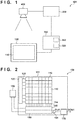
- Fig. 1 shows an example of the arrangement of a radiation imaging system 101 using a radiation imaging apparatus 100 according to the first embodiment of the present invention.
- the radiation imaging system 101 using the radiation imaging apparatus 100 is a system for obtaining a radiation image by an energy subtraction method.
- the energy subtraction method is a method of processing a plurality of radiation images obtained by a plurality of times of imaging using radiations having different energies with respect to an object, thereby obtaining new radiation images (for example, a bone image and a soft tissue image).
- the radiation imaging system 101 is configured to obtain an electrical signal (image signal) for generating a radiation image by electrically obtaining an optical image by imaging, which is converted from radiation entering the radiation imaging apparatus 100.
- the radiation imaging system 101 includes the radiation imaging apparatus 100, a radiation source 400 for irradiation with radiation, an exposure control unit 300 that controls the radiation source 400, and a system control unit 350 that controls the exposure control unit 300 (radiation source 400) and the radiation imaging apparatus 100.
- the system control unit 350 can be constituted by a computer (processor) and a memory storing programs to be provided to the computer.
- the system control unit 350 also includes a signal processing unit 352 that processes signals supplied from the radiation imaging apparatus 100.
- the signal processing unit 352 can be formed from some of the programs stored in the memory of the system control unit 350.
- the signal processing unit 352 may be installed independently of the system control unit 350 and constituted by a computer (processor) and a memory storing programs to be provided to the computer.
- the system control unit 350 may be totally or partially formed from a DSP (digital signal processor) or PLA (programmable logic array).
- the system control unit 350 and the signal processing unit 352 may be designed and manufactured by a logic synthesis tool based on files describing its operations.
- the system control unit 350 may function as a user interface of the radiation imaging system 101.
- the system control unit 350 can include, for example, an input unit that allows the user to input imaging conditions for obtaining a radiation image and a display unit such as a display for checking input information.
- the exposure control unit 300 controls irradiation with radiation by the radiation source 400.
- the exposure control unit 300 may have, for example, an exposure switch and notify the system control unit 350 of information indicating the timing of emitting radiation in addition to causing the radiation source 400 to emit radiation in response to turning on of the exposure switch by the user.
- the exposure control unit 300 may also cause the radiation source 400 to emit radiation in accordance with a command from the system control unit 350.
- the radiation source 400 has a function of changing the energy (wavelength) of radiation.
- the radiation source 400 can change the energy of radiation by, for example, changing a tube voltage (a voltage to be applied between the cathode and the anode of the radiation source 400) under the control of the exposure control unit 300.
- the radiation source 400 can emit radiations having a plurality of energy values different from each other.
- the radiation imaging apparatus 100 includes a pixel array 110 including a plurality of pixels.
- Each of the plurality of pixels includes a conversion unit that converts incident radiation into an electrical signal (for example, charge), a reset unit that resets the conversion unit, and a sample/hold circuit for holding image signals generated by the conversion unit.
- Each pixel may be configured to directly convert radiation into an electrical signal or to convert radiation into light such as visible light and then convert the converted light into an electrical signal. In the latter case, each pixel can use a scintillator for converting radiation into light.
- the scintillator can be shared by a plurality of pixels constituting the pixel array 110.
- the radiation imaging apparatus 100 and the system control unit 350 are arranged independently of each other. However, all or part of the function of the system control unit 350 may be incorporated in the radiation imaging apparatus 100. In addition, part of the function of the radiation imaging apparatus 100 may be incorporated in the system control unit 350.
- Fig. 2 shows an example of the arrangement of the radiation imaging apparatus 100.
- the radiation imaging apparatus 100 includes an imaging unit 111 and a control unit 130 for controlling the imaging unit 111.
- the imaging unit 111 includes the pixel array 110 having a plurality of pixels 112, a row selection circuit 120, a readout circuit 140, a column selection circuit 150, an amplification unit 160, and an AD conversion unit 170.
- the plurality of pixels 112 are arranged to form a plurality of rows and a plurality of columns in an array pattern.
- the pixel array 110 is constituted by the 8 row ⁇ 8 column pixels 112. In practice, however, more pixels 112 can be arranged.
- the pixel array 110 can have a dimension of 17 inches and about 3000 row ⁇ about 3000 column pixels 112.
- the row selection circuit 120 selects a row, of the pixel array 110 in which the plurality of pixels 112 are arranged, which outputs signals.
- the row selection circuit 120 selects a row by driving a row control signal line 122.
- the readout circuit 140 reads out signals from the pixels 112 of the row, of the plurality of rows of the pixel array 110, which is selected by the row selection circuit 120.
- the readout circuit 140 reads out signals corresponding to a plurality of columns which are output to a plurality of column signal lines 114 of the pixel array 110.
- the column signal lines 114 of the respective columns can include, for example, a plurality of signal lines that transmit a plurality of image signals detected by the pixels 112.
- image signals corresponding to the radiation detected by the pixels 112 and noise levels of thermal noise or the like of the pixels 112 can be respectively output to a plurality of signal lines included in the column signal lines 114.
- the readout circuit 140 can be configured to read out the respective image signals and noise levels output to the column signal lines 114.
- the column selection circuit 150 selects signals corresponding to a plurality of columns read out from the pixels 112 of the row of the pixel array 110 which is selected by the readout circuit 140 in a predetermined order.
- the amplification unit 160 amplifies the signals selected by the column selection circuit 150.
- the amplification unit 160 may be configured as a differential amplifier that amplifies the difference between an image signal and a noise level forming a pair or to amplify each of them independently.
- the AD conversion unit 170 A/D-converts a signal OUT output from the amplification unit 160 and outputs the digital signal DOUT as an image signal.
- the control unit 130 controls the row selection circuit 120, the readout circuit 140, the column selection circuit 150, and the amplification unit 160, and causes the radiation imaging apparatus 100 to output the image signals generated by the pixels 112 arranged in the pixel array 110 of the imaging unit 111.
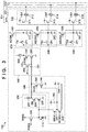
- Fig. 3 shows an example of the arrangement of one pixel 112 arranged in the pixel array 110.
- the pixel 112 includes a conversion element 210, a reset switch 220, an amplification circuit 230, a sensitivity changing unit 240, a clamp circuit 260, sample/hold circuits 270, 280, and 290, and an output circuit 310.
- the conversion element 210 functions as a conversion unit that converts incident radiation into an electrical signal (image signal).
- the conversion element 210 can be constituted by a scintillator that converts radiation shared by a plurality of pixels into light and a photoelectric conversion element that converts converted light into an electrical signal.
- the conversion element 210 includes a charge accumulation unit that accumulates electrical signals (charge) converted from radiation, that is, electrical signals corresponding to radiation.
- the charge accumulation unit is connected to the input terminal of the amplification circuit 230.
- the amplification circuit 230 includes transistors 235 and 236 and a current source 237.
- the transistor 235 is connected to the current source 237 via the transistor 236.
- the transistor 235 and the current source 237 constitute a source follower circuit.
- the transistor 236 is an enable switch that is turned on by activating an enable signal EN to activate the source follower circuit constituted by the transistor 235 and the current source 237.
- the charge accumulation unit of the conversion element 210 and the gate of the transistor 235 function as a charge voltage conversion unit CVC that converts the charge accumulated in the charge accumulation unit into a voltage.
- the reset switch 220 can include a transistor having a first main electrode (drain) connected to the charge accumulation unit of the conversion element 210, a second main electrode (source) to which the reset potential VRES is applied, and a control electrode (gate). An ON voltage is applied to the control electrode of the transistor to render the first and second main electrodes conductive, thereby resetting the charge accumulation unit of the conversion element 210.
- the clamp circuit 260 includes a clamp capacitor 261, transistors 262, 263, and 264, and a current source 265.
- the clamp circuit 260 clamps the reset noise level output from the amplification circuit 230 in accordance with the potential of the reset charge voltage conversion unit CVC by using the clamp capacitor 261.
- the clamp circuit 260 is a circuit for canceling a reset noise level from the image signal output from the amplification circuit 230 in accordance with the charge (electrical signal) converted by the conversion element 210.
- a reset noise level includes kTC noise when the charge voltage conversion unit CVC is reset.
- a clamp operation is performed by turning on the transistor 262 by activating a clamp signal PCL and then turning off the transistor 262 by inactivating the clamp signal PCL.
- the output side of the clamp capacitor 261 is connected to the gate of the transistor 263.
- the source of the transistor 263 is connected to the current source 265 via the transistor 264.
- the transistor 263 and the current source 265 constitute a source follower circuit.
- the transistor 264 is an enable switch that is turned on by activating an enable signal EN0 supplied to the gate of the transistor 264 to activate the source follower circuit constituted by the transistor 263 and the current source 265.
- the output circuit 310 includes transistors 311, 313, and 315 and row selection switches 312, 314, and 316.
- the transistors 311, 313, and 315 form source follower circuits together with current sources (not shown) respectively connected to signal lines 321, 322, and 323 of the column signal lines 114.
- the sample/hold circuit 280 can hold (sample/hold) the image signal output from the clamp circuit 260 in accordance with the charge generated by the conversion element 210.
- the sample/hold circuit 280 includes a switch 281 and a capacitor 282.
- the switch 281 is turned on by activating a sample/hold signal TS1.
- the image signal output from the clamp circuit 260 is written in the capacitor 282 via the switch 281 by activating the sample/hold signal TS1.
- the pixel 112 can include an additional sample/hold circuit 290 for writing image signals.
- the sample/hold circuit 290 may sample an image signal different from the image signal sampled by the sample/hold circuit 280.
- the sample/hold circuit 290 can sample/hold the image signal output from the clamp circuit 260 in accordance with the charge generated by the conversion element 210.
- the sample/hold circuit 290 includes a switch 291 and a capacitor 292.
- the switch 291 is turned on by activating a sample/hold signal TS2.
- the image signal output from the clamp circuit 260 is written in the capacitor 292 via the switch 291 by activating the sample/hold signal TS2.
- the pixel 112 may further have an additional sample/hold circuit for writing image signals. That is, the pixel 112 may have an arbitrary number of sample/hold circuits for writing image signals.
- the sample/hold circuit 270 can sample/hold the noise level of the clamp circuit 260.
- the sample/hold circuit 270 includes a switch 271 and a capacitor 272. The switch 271 is turned on by activating a sample/hold signal TN. The noise level output from the clamp circuit 260 is written in the capacitor 272 via the switch 271 by activating the sample/hold signal TN.
- the sample/hold circuit 270 may also be used to hold a radiation signal as a signal output from the clamp circuit 260 in accordance with the charge generated by the conversion element 210.
- a row selection signal VST When a row selection signal VST is activated, the signals held in the sample/hold circuits 270, 280, and 290 are respectively output to the signal lines 321, 322, and 323 constituting the column signal lines 114. More specifically, a signal N corresponding to a signal (noise level or image signal) held by the sample/hold circuit 270 is output to the signal line 321 via the transistor 311 and the row selection switch 312. A signal S1 corresponding to an image signal held by the sample/hold circuit 280 is output to the signal line 322 via the transistor 313 and the row selection switch 314. A signal S2 corresponding to an image signal held by the sample/hold circuit 290 is output to the column signal line 323 via the transistor 315 and the row selection switch 316.
- the pixel 112 may include addition switches 301, 302, and 303 for adding signals among the plurality of pixels 112.
- addition mode signals ADDN, ADDS1, and ADDS2 are activated.
- Activating the addition mode signal ADDN will connect the capacitors 272 of the plurality of pixels 112 to each other, thereby averaging the signals.
- Activating the addition mode signal ADDS1 will connect the capacitors 282 of the plurality of pixels 112 to each other, thereby averaging the signals.
- Activating the addition mode signal ADDS2 will connect the capacitors 292 of the plurality of pixels 112 to each other, thereby averaging the signals.
- the pixel 112 can include the sensitivity changing unit 240.
- the sensitivity changing unit 240 includes switches 241 and 242, capacitors 243 and 244, and transistors 245 and 246. Activating a change signal WIDE will turn on the switch 241 to add the capacitance value of the capacitor 243 to the capacitance value of the charge voltage conversion unit CVC. This decreases the sensitivity of the pixel 112.
- an enable signal ENW may be activated.
- activating a change signal WIDE2 will turn on the switch 242 to add the capacitance value of the capacitor 244 to the capacitance value of the charge voltage conversion unit CVC. This further decreases the sensitivity of the pixel 112.
- the dynamic range can be widened by adding a function of decreasing the sensitivity of the pixel 112.
- the number of capacitors arranged in the sensitivity changing unit 240 may be one or three or more and be set, as needed, in accordance with the dynamic range required for the radiation imaging apparatus 100.
- the reset signal PRES, the enable signal EN, the clamp signal PCL, the enable signal EN0, the sample/hold signals TN, TS1, and TS2, and the row selection signal VST described above are control signals output from the row selection circuit 120 under the control of the control unit 130. As shown in Fig. 2 , these control signals are input from the row selection circuit 120 to transistors and switches corresponding to the pixel 112 via the row control signal line 122.
- the abscissa represents the time.
- radiation energy represents the waveform of radiation that is emitted from the radiation source 400 and irradiates the radiation imaging apparatus 100.
- PRES represents the reset signal PRES.
- TS1 represents the sample/hold signal TS1.
- DOUT represents an output from the AD conversion unit 170.
- the system control unit 350 controls the synchronization between the emission of radiation from the radiation source 400 and the operation of the radiation imaging apparatus 100.
- the control unit 130 controls the operation of the radiation imaging apparatus 100.
- radiation irradiation conditions at the time of obtaining a radiation image by imaging are set, including the energy values of radiation, such as the tube voltage and tube current of the radiation source 400, and the irradiation time of radiation.
- the clamp signal PCL is also activated over a predetermined period, thereby clamping a noise level in the clamp circuit 260.
- the conversion element 210 is reset by activating the reset signal PRES over a predetermined period.
- the radiation source 400 emits radiation 511 and radiation 512 having different energy values under the control of the system control unit 350.
- the radiation source 400 emits first the radiation 511 having a low energy value and then the radiation 512 having a higher energy value than the radiation 511 under the control of the system control unit 350.
- the emission order of radiations having different energy values is not limited to this.
- the radiation source 400 may emit radiation having a high energy value first.
- the radiation 511 and the radiation 512 may be emitted consecutively over time or there may be time interval between emission of the radiation 511 and the radiation 512.
- the user may select irradiation conditions for the radiation 511 and the radiation 512 as needed in accordance with an object from an irradiation condition table like that shown in Fig. 5 , which is stored in a storage unit 354 provided in the system control unit 350.
- the radiation imaging apparatus 100 may also include a camera or gage for measuring the thickness of an object.
- the control unit 130 may select irradiation conditions concerning the radiation 511 and the radiation 512 from the table in accordance with information such as the detected thickness of the object.
- an object may be imaged in advance with a low dose to estimate, for example, the thickness of the object from the transmission dose of radiation.
- the control unit 130 may then select irradiation conditions concerning the radiation 511 and the radiation 512 from the table in accordance with the estimated thickness of the object.
- irradiation with radiation is performed twice. However, this is not exhaustive. As shown in Fig. 8 , the rising and falling of radiation during one irradiation with radiation 801 may be used to perform imaging with radiation 800 and imaging with radiation 802 before and after the operation of the first sample/hold signal TS1.
- the control unit 130 causes the imaging unit 111 to perform first imaging and second imaging after the first imaging for generation of one energy subtraction image.
- the sample/hold circuit 280 samples the image signal generated by the pixel 112 by irradiation with the radiation 511 after irradiation with the radiation 511 and before irradiation with the radiation 512 in accordance with the sample/hold signal TS1 from the control unit 130. Thereafter, the conversion element 210 is reset by activating the reset signal PRES over a predetermined time.
- the second imaging is then performed by irradiation with the radiation 512.
- the control unit 130 causes the readout circuit 140 to read out the image signal obtained by the first imaging by irradiation with the radiation 512 and held in the sample/hold circuit 280 while the second imaging is performed by irradiation with the radiation 512.
- the image signal obtained by irradiation with the radiation 511 is output as an image signal 513 via the column selection circuit 150, the amplification unit 160, and the AD conversion unit 170.
- the sample/hold circuit 280 samples the image signal generated by the pixel 112 by irradiation with the radiation 512 in accordance with the sample/hold signal TS1.
- the image signal generated by irradiation with the radiation 512 is processed like the image signal generated by irradiation with the radiation 511 and is output as an image signal 514 from the AD conversion unit 170.
- the radiation imaging apparatus 100 can shorten the interval between two imaging operations by concurrently performing reading out of the signal obtained by the first imaging and accumulation of the signal obtained by the second imaging in this manner. This makes it possible to improve the performance of the radiation imaging apparatus 100 by providing the sample/hold circuit 280 in obtaining an energy subtraction image of a fast moving object.
- the signal processing unit 352 of the system control unit 350 obtains a subtraction image by processing the image signal 513 and the image signal 514 in accordance with an energy subtraction method.
- various methods can be used as energy subtraction methods.
- a bone image and a soft tissue image can be obtained by calculating differences between the radiation image obtained by low-energy radiation (radiation 511) and the radiation image obtained by high-energy radiation (radiation 512).
- a bone image and a soft tissue image may be obtained by solving non-linear simultaneous equations based on the radiation image obtained by low-energy radiation and the radiation image obtained by high-energy radiation.
- a contrast medium image and a soft tissue image can be obtained based on the radiation image obtained by low-energy radiation and the radiation image obtained by high-energy radiation.
- an electron density image and an effective atomic number image can be obtained based on the radiation image obtained by low-energy radiation and the radiation image obtained by high-energy radiation.
- radiation irradiation conditions include, for example, tube voltage values and tube current values for setting the energy values of radiations emitted for two imaging operations and the irradiation times of radiation. It is possible to calculate the amounts of noise in energy subtraction images after four arithmetic operations between a high-energy image and a low-energy image according to equations (1), (2), and (3) given below.
- M 1 be the pixel value of a high-energy image
- ⁇ 1 be the noise value of the high-energy image
- M 2 be the pixel value of a low-energy image
- ⁇ 2 be the noise value of the low-energy image.
- M 1 ⁇ ⁇ 1 ⁇ M 2 ⁇ ⁇ 2 M 1 ⁇ M 2 ⁇ ⁇ 1 2 + ⁇ 2 2
- M 1 ⁇ ⁇ 1 ⁇ M 2 ⁇ ⁇ 2 M 1 ⁇ M 2 ⁇ M 2 ⁇ ⁇ 1 2 + M 1 ⁇ ⁇ 2 2
- M 1 ⁇ ⁇ 1 / M 2 ⁇ ⁇ 2 M 1 M 2 ⁇ 1 M 2 ⁇ ⁇ 1 2 + M 1 M 2 2 ⁇ ⁇ 2 2
- Bone suppression processing is image processing of removing bone portions from the radiation image obtained by using a low-energy image and a high-energy image.
- image processing is often performed by using equation (4).
- M cor be the pixel value of an energy subtraction image
- ⁇ cor be the noise value of the energy subtraction image
- I be the dose of radiation
- ⁇ be a correction coefficient (constant) for weighting a high-energy image and a low-energy image.
- M cor ⁇ ⁇ cor M 1 ⁇ ⁇ 1 ⁇ ⁇ ⁇ M 2 ⁇ ⁇ 2
- ⁇ cor ⁇ 1 2 + ⁇ ⁇ ⁇ 2 2
- equation (7) In order to minimize the noise value ⁇ cor of an energy subtraction image in equation (5) from a relational expression (equation (6)) concerning an arithmetic/geometric average, equation (7) must hold.
- ⁇ 1 2 + ⁇ ⁇ ⁇ 2 2 ⁇ 2 ⁇ ⁇ 1 ⁇ 2 ⁇ 1 2 ⁇ ⁇ ⁇ 2 2
- Equation (9) indicates that the noise of a radiation image is proportional to the square root of a transmission dose because the number of arrival radiation particles follows a Poisson distribution.
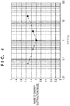
- the noise values ⁇ 1 and ⁇ 2 as the amounts of noise in a high-energy image and a low-energy image vary for each object thickness or material. For this reason, it is not always possible to perform imaging under ideal radiation irradiation conditions. Accordingly, for example, a radiation irradiation condition table is generated such that ⁇ 1 /( ⁇ ⁇ ⁇ 2 ) falls within the range of 1/3 to 3. Fig.
- FIG. 6 is a graph showing the transition of the amount of noise in an energy subtraction image relative to the amount of noise in a low-energy image and the amount of noise in a high-energy image.
- setting ⁇ 1 /( ⁇ ⁇ ⁇ 2 ) within the range of 1/3 to 3 makes it possible to suppress an increase in the amount of noise to about 10% or less from the optimal amount of noise in an energy subtraction image.
- the amount of noise in an image signal is determined based on relational expressions (equations (1), (2), and (3)) concerning error propagation in four arithmetic operations.
- Radiation irradiation conditions are set by, for example, user's input to the system control unit 350.
- the irradiation conditions are transmitted to the control unit 130.
- the control unit 130 controls the sample/hold circuit 280 to reduce the difference between the amount of noise contained in the image signal obtained by first imaging and the amount of noise contained in the image signal obtained by second imaging in accordance with the radiation irradiation conditions set in advance. More specifically, the control unit 130 controls the timing when the sample/hold circuit 280 samples an image signal by using the sample/hold signal TS1 in order to obtain the image signal generated by irradiation with the radiation 511 in the first imaging. Likewise, the control unit 130 controls the timing when the sample/hold circuit 280 samples an image signal by using the sample/hold signal TS1 in order to obtain the image signal generated by irradiation with the radiation 512 in the second imaging.
- radiation irradiation conditions include information such as tube voltage values and tube current values for setting the energy values of radiations, the irradiation times of radiation, and temporal changes in radiation energy.
- Information about temporal changes in the waveform of radiation energy may be stored in the storage unit 354 or the like in advance in accordance with conditions such as a plurality of energy values of radiations. Such information may be read out from the storage unit 354 upon setting of an energy value.
- Radiation irradiation conditions are set by user's input to the system control unit 350.
- the irradiation conditions are transmitted to the control unit 130.
- the control unit 130 controls the sample/hold circuit 280 to reduce the difference between the amount of noise contained in the image signal obtained by the first imaging and the amount of noise contained in the image signal obtained by the second imaging in accordance with radiation irradiation conditions set in advance.
- the control unit 130 controls the timing when the sample/hold circuit 280 samples an image signal by using the sample/hold signal TS1 and the reset signal PRES so as to reduce the difference between the amounts of noise in accordance with irradiation conditions set in advance.
- control unit 130 causes the sample/hold circuit 280 to sample the first image signal at the timing of the radiation 800 by using the sample/hold signal TS1 during irradiation with the radiation 801.
- the control unit 130 then resets the conversion element 210 by using the reset signal PRES.
- the control unit 130 also causes the sample/hold circuit 280 to sample the second image signal at the timing of the radiation 802 by using the sample/hold signal TS1.
- the control unit 130 controls the sample/hold circuit 280 to sample the image signal at timings such that the amount of noise in the image signal obtained by low-energy radiation to which a correction coefficient is applied becomes 1/3 times or more and 3 times or less the amount of noise in the image signal obtained by high-energy radiation.
- This embodiment has exemplified the form of processing for separating a bone image from a soft tissue image by differential processing for a low-energy image and a high-energy image.
- the present invention is not limited to this form.
- the present invention can be applied to a case in which a bone image is separated from a soft tissue image by solving non-linear simultaneous equations using a low-energy image and a high-energy image or a case in which an electron density image is separated from an effective atomic number image.
- the energy value of radiation is changed by changing the tube voltage and tube current of the radiation source 400.
- this is not exhaustive. For example, it is possible to obtain images from radiations having different energies by switching between insertion and non-insertion of a beam hardening filter without changing the tube voltage and tube current of the radiation source 400.
- control unit 130 controls the radiation imaging apparatus 100 to cause the sample/hold circuit 280 to sample image signals in accordance with the amounts of noise contained in the image signals generated by imaging using radiations with two different energies. This makes it possible to suppress noise in an energy subtraction image and obtain an energy subtraction image with high image quality.
- the embodiment can be configured to reduce noise in a subtraction image by only holding a radiation irradiation condition table in the storage unit 354 without increasing an exposure dose. This is advantageous in facilitating system construction because there is no need to add any special arrangement to the radiation imaging system 101 except for holding an irradiation condition table.
- Fig. 7 is a flowchart showing the processing from imaging of an object using a radiation imaging apparatus 100 according to the second embodiment of the present invention to displaying of an energy subtraction image.
- the arrangements of the radiation imaging apparatus 100 and a radiation imaging system 101 may be the same as those of the first embodiment described above, and hence a description will be omitted.
- step S701 in accordance with user's operations on a system control unit 350, radiation irradiation conditions at the time of imaging are set, including the energy values of radiation, such as the tube voltage and tube current of a radiation source 400, the irradiation time of radiation, and temporal changes in the waveform of radiation applied.
- the radiation imaging apparatus 100 includes a storage unit 354, the user may select appropriate conditions from the radiation irradiation conditions stored in the storage unit 354 in accordance with an object.
- conditions are read out from the storage unit 354 and set, including the energy value of radiation and a temporal change in waveform, which correspond to the characteristics of the radiation source 400, and the irradiation time of radiation.
- the radiation imaging apparatus 100 may include a camera or gage for measuring the thickness of an object.
- a control unit 130 may select appropriate conditions from the radiation irradiation conditions stored in the storage unit 354 in accordance with the detected thickness of the object.
- an object may be imaged in advance with a low dose to estimate, for example, the thickness of the object from the transmission dose of radiation. The control unit 130 may then determine appropriate radiation irradiation conditions from the estimated object thickness.
- the control unit 130 determines the timing when a sample/hold circuit 280 samples an image signal in the first imaging in accordance with the set irradiation conditions. At this time, the control unit 130 may also tentatively determine the timing when the sample/hold circuit 280 samples an image signal in the second imaging.
- the first imaging is performed to obtain a radiation image in step S702.
- the generated image signal is output to a signal processing unit 352.
- the control unit 130 analyzes the amount of noise contained in the image signal for the radiation image obtained by the first imaging obtained in step S702 and output to the signal processing unit 352.
- the control unit 130 may analyze an image signal of a predetermined region of an imaging unit 111 as a region of interest where the amount of noise is analyzed.
- the control unit 130 may select an image signal of an arbitrary portion of the imaging unit 111 by using a region extraction technique or the like.
- control unit 130 may select, as a predetermined region, a region with a small transmission dose, such as a lumbar vertebra having a thick bone.
- a suitable filter or the like may be provided in the visual field of the imaging unit 111 to let the user select the place provided with the filter as a predetermined region.
- the control unit 130 may recognize the place provided with the filter as a region with a small transmission dose and select the region as a predetermined region.
- the control unit 130 determines the amount of noise contained in the image signal of the radiation image obtained by the first imaging by performing processing such as obtaining the standard deviation (noise) of an image signal, of the image signal of the high-energy image, which corresponds to the predetermined region.
- step S704 the control unit 130 determines a second imaging condition, more specifically the timing of sampling an image signal, based on the amount of noise determined from the analysis result of the amount of noise contained in the radiation image obtained by the first imaging in step S703.
- the control unit 130 may correct the timing of sampling in accordance with the determined amount of noise.
- the timing of sampling the image signal obtained by the second imaging is obtained to minimize the noise of an energy subtraction image by the method described above in the first embodiment.
- control unit 130 also determines the timing when the sample/hold circuit 280 samples an image signal, based on the amount of noise decided based on relational expressions (equations (1), (2), and (3)) concerning error propagation in the four basic arithmetic operations.
- the control unit 130 Upon determining the timing of sampling in the second imaging, the control unit 130 controls the imaging unit 111 to perform the second imaging in step S705. At this time, the control unit 130 may control an AEC (Auto Exposure Control) function of stopping irradiation with radiation when a desired transmission dose is reached or the dose of radiation applied by using a phototimer or the like. In this case, when the transmission dose of a region set in advance by the user or the like reaches a desired dose, the control unit 130 may output, to the system control unit 350, a signal for stopping irradiation with radiation from the radiation source 400. In accordance with this signal, the system control unit 350 controls the radiation source 400 to stop irradiation with radiation.
- AEC Automatic Exposure Control
- step S706 the signal processing unit 352 performs energy subtraction processing by using the image signals obtained by two imaging operations and output from the imaging unit 111.
- step S707 the energy subtraction image having undergone the energy subtraction processing is output from the signal processing unit 352 and displayed on a display device (not shown) such as a display.
- a display device such as a display.
- radiation images obtained by imaging operations with different radiation energy values may be output from the signal processing unit 352 and displayed on the display device.
- the amount of noise contained in the image signal generated by the first imaging is determined. Thereafter, the timing when the sample/hold circuit samples the image signal obtained by the second imaging is set in accordance with the amount of noise.
- the signal processing unit 352 needs to analyze the radiation image obtained by the first imaging, and hence the arrangement of the radiation imaging system 101 can be complicated as compared with the first embodiment.
- communication between the control unit 130 and the signal processing unit 352 can increase as compared with the first embodiment. Accordingly, a functional portion, of the signal processing unit 352, which analyzes the amount of noise in a radiation image may be provided in, for example, the radiation imaging apparatus 100 or the control unit 130.
- an energy subtraction image may be generated from three or more radiation images obtained by three or more imaging operations.
- the control unit 130 may control the timing of sampling the image signal obtained by each imaging operation so as to reduce the amount of noise in the energy subtraction image generated in the above manner.
- the control unit 130 controls the timing when the sample/hold circuit 280 samples image signals so as to reduce the amounts of noise in two obtained image signals.
- the third embodiment will exemplify a method of generating an energy subtraction image with a small amount of noise from a plurality of image signals obtained by a plurality of times of imaging during one irradiation with radiation using the sample/hold circuit 280.
- the arrangements of a radiation imaging apparatus 100 and a radiation imaging system 101 may be the same as those of the first and second embodiments, and hence a description of the arrangement will be omitted.
- Fig. 8 consider a case in which the rising and falling of radiation during one irradiation with radiation 801 are used to perform imaging a plurality of times during one irradiation with radiation as irradiation with radiations with different energies before and after an operation using a sample/hold signal TS1 and a reset signal PRES.
- the dose and energy value of radiation applied in each imaging change depending on the timing of the sample/hold signal TS1, the dose and energy value of radiation applied in each imaging change.
- the amount of noise in a subtraction image decreases with an increase in the energy difference between two radiation images.
- obtaining an image signal for generating a radiation image midway along the rising waveform of radiation like the radiation 804 can increase the energy difference from the radiation image generated from the image signal obtained by the radiation 806.
- this can reduce the dose of radiation 804 and increase the amount of noise in an energy subtraction image. This makes it necessary to properly adjust the energy difference between two radiation images and the amounts of noise contained in the respective image signals.
- a method of adjusting the energy difference between two radiation images and the amounts of noise will be described in detail with reference to Fig. 9 .
- Fig. 9 is a flowchart showing the processing from imaging of an object using the radiation imaging apparatus 100 according to the third embodiment of the present invention to displaying of an energy subtraction image.
- imaging conditions include information such as the energy value of radiation, the irradiation time of radiation, and a temporal change in the waveform of radiation energy.
- the imaging conditions also include the number of times of imaging during one irradiation with radiation.
- a radiation source 400 emits radiation in accordance with the set conditions in step S902.
- the control unit 130 of the radiation imaging apparatus 100 causes an imaging unit 111 to perform imaging a plurality of times during one irradiation with radiation.
- the control unit 130 causes the readout circuit 140 to read out a plurality of image signals sampled by sample/hold circuits 270, 280 and 290 in each of a plurality of times of imaging.
- the radiation imaging apparatus 100 includes the sample/hold circuits 270, 280, and 290. Accordingly, the radiation imaging apparatus 100 can shorten the interval between two imaging operations by concurrently performing reading out of the signal obtained by the first imaging and accumulation of the signal obtained by the second imaging.
- including the sample/hold circuits 270, 280, and 290 allows the radiation imaging apparatus 100 to obtain more image signals at shorter intervals during one irradiation with radiation.
- the image signals generated by a plurality of times of imaging and read out by a readout circuit 140 are transferred to a signal processing unit 352.
- the arrangement shown in Fig. 10 is configured to obtain 14 image signals by performing 14 imaging operations during one irradiation with radiation.
- the number of image signals obtained is not limited to this.
- the number of image signals obtained may be 13 or less or 15 or more.
- imaging need not be performed at equal intervals, and the sample/hold circuits 270, 280, and 290 can sample image signals at arbitrary timings under the control of the control unit 130.
- the signal processing unit 352 sorts obtained radiation images based on information about radiation energy. For example, the signal processing unit 352 may sort a plurality of image signals according to the order of the differences between high-energy portions and low-energy portions of the plurality of image signals as information about radiation energy. In this case, if an object is the human body, the differences in transmittance between bone portions and fat portions may be used as information about radiation energy. In addition, the signal processing unit 352 may sort a plurality of image signals according to the order of the energy values of high-energy portions of radiation of the plurality of image signals as information about radiation energy.
- the energy values of high-energy portions may be the pixel values of pixels corresponding to highest-energy portions of the obtained image signals.
- the energy value of a highest-energy portion may be the average value of the pixel values of pixels corresponding to 20% of the highest-energy portion of an obtained image signal.
- the first image signal obtained by imaging is formed from a rising portion of radiation and hence can be an image signal of a low-energy image.
- an image signal obtained by imaging after the rising of the radiation can be an image signal of a high-energy image.
- the last image signal obtained by imaging is formed from a falling portion of the radiation and hence can be an image signal of a low-energy image.
- step S904 the signal processing unit 352 divides the plurality of sorted image signals into image signals used for a low-energy image and image signals used for a high-energy image.
- the divided image signals are combined into an image signal for a low-energy image and an image signal for a high-energy image.
- the image signal for the low-energy image and the image signal for the high-energy image are generated by averaging or weighting and averaging signals, of a plurality of image signals, which are combined into an image signal for a low-energy image and an image signal for a high-energy image.
- the signal processing unit 352 may divide the signals into two groups by using an arbitrary energy value as a threshold.
- the signal processing unit 352 may divide image signals according to the amounts of noise contained in the respective image signals in consideration of an energy subtraction image obtained in the subsequent step. For example, image signals may be divided such that the difference between the amounts of noise respectively contained in a combined image signal for a low-energy image and a combined image signal for a high-energy image falls within a predetermined range.
- a plurality of image signals may be divided based on relational expressions concerning error propagation such that the amount of noise contained in a combined image signal for a low-energy image becomes 1/3 times or more and 3 times or less the amount of noise contained in an image signal for a high-energy image.
- a plurality of combinations of combined image signals for low-energy images and combined image signals for high-energy images may be generated, with differences in the amount of noise between the respective combined signals falling within a predetermined range. The following is a case in which a plurality of combinations are generated.
- step S906 the signal processing unit 352 analyzes the amounts of noise contained in the respective generated energy subtraction images by using, for example, the standard deviations of the pixel values of predetermined portions of the respective energy subtraction images. For example, the signal processing unit 352 may select a region with a small transmission dose as a predetermined region. The signal processing unit 352 can analyze the amount of noise by using the same method as that described in the second embodiment. Each analysis value is stored in a storage unit 354 so as to be referred to later.
- step S907 the signal processing unit 352 determines whether energy subtraction images have been generated from all combinations of the obtained image signals for low-energy images and the obtained image signals for high-energy images. If NO in step S907, the process returns to step S904 to generate an energy subtraction image by a combination pattern from which no energy subtraction image has been generated. If energy subtraction images have been generated from all combinations, the process shifts to step S908. Note however that energy subtraction images are generated from arbitrary combinations but need not be generated from all combinations.
- step S908 the signal processing unit 352 outputs an energy subtraction image, of the energy subtraction images generated from the plurality of combinations, which contains the smallest amount of noise.
- the output energy subtraction image is displayed on a display device (not shown) such as a display.
- the signal processing unit 352 determines combinations for combining a plurality of image signals so as to minimize the amount of noise contained in an energy subtraction image that is actually output. This makes it possible to obtain an energy subtraction image in which noise has been reliably reduced.
- the signal processing unit 352 because it is necessary to perform many imaging operations and output a plurality of image signals to the signal processing unit 352, the signal processing unit 352 may be provided in the radiation imaging apparatus 100.
- the sample/hold circuits 270, 280, and 290 may sample generated signals a plurality of times without performing any reset operation, and differences between the respective signals may be used as image signals.
Abstract
Description
- The present invention relates to a radiation imaging apparatus and a radiation imaging system.
- A radiation imaging apparatus using an FPD (flat panel detector) formed from a semiconductor material is widely used in medical image diagnosis and non-destructive inspection. As one type of imaging method using such an FPD, there is known a method of obtaining an energy subtraction image by using radiations having different energy components. The time interval at which a plurality of radiation images are obtained by imaging is several sec or more in a radiation imaging apparatus for still images, about 100 msec in a radiation imaging apparatus for normal moving images, and about 10 msec in a radiation imaging apparatus for fast moving images. When an object moves during this time interval, the movement of the object causes artifacts. Accordingly, it is difficult to obtain an energy subtraction image of a fast moving object such as the heart.
PTL 1 discloses a technique of obtaining an energy subtraction image of a fast moving object by transferring a first imaging signal to a sample/hold node and then reading out the first signal from the sample/hold node while accumulating a second imaging signal. The X-ray imaging system disclosed inPTL 1 concurrently performs reading out of a first imaging signal and accumulation of a second imaging signal to shorten the interval between the two imaging operations, thereby obtaining an energy subtraction image of a fast moving object. - PTL 1: Japanese
PCT National Publication No. 2009-504221 - The noise contained in an energy subtraction image depends on the amounts of noise in a radiation image obtained by imaging with high-energy radiation and a radiation image obtained by imaging with low-energy radiation. In order to improve the image quality of an energy subtraction image, it is necessary to consider the amounts of noise respectively contained in a high-energy image and a low-energy image.
PTL 1 makes no reference to the amounts of noise contained in signals obtained by the respective imaging operations. - The present invention has an object to provide a technique advantageous in improving the image quality of an energy subtraction image in a radiation imaging apparatus.
- In consideration of the above problem,
a radiation imaging apparatus according to an embodiment of the present invention is a radiation imaging apparatus including an imaging unit including a plurality of pixels and a control unit, characterized in that each of the plurality of pixels includes a conversion unit configured to generate an image signal corresponding to incident radiation and a sample/hold circuit configured to hold an image signal generated by the conversion unit, and the control unit causes the imaging unit to perform first imaging and second imaging after the first imaging to generate one energy subtraction image, and controls a timing of causing the sample/hold circuit in the first imaging to sample a first image signal obtained by the first imaging and a timing of causing the sample/hold circuit in the second imaging to sample a second image signal obtained by the second imaging in accordance with radiation irradiation conditions set in advance so as to reduce a difference between an amount of noise contained in the first image signal and an amount of noise contained in the second image signal. - The above means provide a technique advantageous in improving the image quality of an energy subtraction image in a radiation imaging apparatus.
- Other features and advantages of the present invention will be apparent from the following description made with reference to the accompanying drawings. Note that the same reference numerals denote the same or similar components throughout the accompanying drawings.
- The accompanying drawings, which are incorporated in and constitute a part of the specification, illustrate presently preferred embodiments of the invention, and together with the general description given above and the detailed description of the preferred embodiments given below, serve to explain the principles of the invention.
-
Fig. 1 is a block diagram showing an example of the arrangement of a radiation imaging system using a radiation imaging apparatus according to an embodiment of the present invention; -
Fig. 2 is a block diagram showing an example of the arrangement of the radiation imaging apparatus inFig. 1 ; -
Fig. 3 is a circuit diagram showing an example of the arrangement of a pixel of the radiation imaging apparatus inFig. 1 ; -
Fig. 4 is a timing chart showing an example of the operation of the radiation imaging system inFig. 1 ; -
Fig. 5 is a view showing examples of radiation irradiation conditions when obtaining an energy subtraction image by imaging in the radiation imaging system inFig. 1 ; -
Fig. 6 is a graph showing the relationship between noise in a high-energy image and a low-energy image and noise in an energy subtraction image; -
Fig. 7 is a flowchart for obtaining an energy subtraction image by imaging using the radiation imaging apparatus inFig. 1 ; -
Fig. 8 is a graph showing waveform examples of radiation; -
Fig. 9 is a flowchart for obtaining an energy subtraction image by imaging using the radiation imaging apparatus inFig. 1 ; -
Fig. 10 is a timing chart showing an example of the operation of the radiation imaging system inFig. 1 ; and -
Fig. 11 is a view schematically showing how image signals are divided to high-energy image signals and low-energy image signals. - Specific embodiments of a radiation imaging apparatus according to the present invention will be described below with reference to the accompanying drawings. Note that radiation according to the present invention can include not only α-rays, β-rays, and γ-rays that are beams generated by particles (including photons) emitted by radioactive decay but also beams having energy equal to or more than the energy of these beams, for example, X-rays, particle rays, and cosmic rays.
- The arrangement and operation of a radiation imaging apparatus according to an embodiment of the present invention will be described with reference to
Figs. 1 to 6 .Fig. 1 shows an example of the arrangement of aradiation imaging system 101 using aradiation imaging apparatus 100 according to the first embodiment of the present invention. In this embodiment, theradiation imaging system 101 using theradiation imaging apparatus 100 is a system for obtaining a radiation image by an energy subtraction method. The energy subtraction method is a method of processing a plurality of radiation images obtained by a plurality of times of imaging using radiations having different energies with respect to an object, thereby obtaining new radiation images (for example, a bone image and a soft tissue image). Theradiation imaging system 101 is configured to obtain an electrical signal (image signal) for generating a radiation image by electrically obtaining an optical image by imaging, which is converted from radiation entering theradiation imaging apparatus 100. - The
radiation imaging system 101 includes theradiation imaging apparatus 100, aradiation source 400 for irradiation with radiation, anexposure control unit 300 that controls theradiation source 400, and asystem control unit 350 that controls the exposure control unit 300 (radiation source 400) and theradiation imaging apparatus 100. - The
system control unit 350 can be constituted by a computer (processor) and a memory storing programs to be provided to the computer. Thesystem control unit 350 also includes asignal processing unit 352 that processes signals supplied from theradiation imaging apparatus 100. Thesignal processing unit 352 can be formed from some of the programs stored in the memory of thesystem control unit 350. Thesignal processing unit 352 may be installed independently of thesystem control unit 350 and constituted by a computer (processor) and a memory storing programs to be provided to the computer. Thesystem control unit 350 may be totally or partially formed from a DSP (digital signal processor) or PLA (programmable logic array). Thesystem control unit 350 and thesignal processing unit 352 may be designed and manufactured by a logic synthesis tool based on files describing its operations. Thesystem control unit 350 may function as a user interface of theradiation imaging system 101. In this case, thesystem control unit 350 can include, for example, an input unit that allows the user to input imaging conditions for obtaining a radiation image and a display unit such as a display for checking input information. - The
exposure control unit 300 controls irradiation with radiation by theradiation source 400. Theexposure control unit 300 may have, for example, an exposure switch and notify thesystem control unit 350 of information indicating the timing of emitting radiation in addition to causing theradiation source 400 to emit radiation in response to turning on of the exposure switch by the user. Theexposure control unit 300 may also cause theradiation source 400 to emit radiation in accordance with a command from thesystem control unit 350. - The
radiation source 400 has a function of changing the energy (wavelength) of radiation. Theradiation source 400 can change the energy of radiation by, for example, changing a tube voltage (a voltage to be applied between the cathode and the anode of the radiation source 400) under the control of theexposure control unit 300. Theradiation source 400 can emit radiations having a plurality of energy values different from each other. - The
radiation imaging apparatus 100 includes apixel array 110 including a plurality of pixels. Each of the plurality of pixels includes a conversion unit that converts incident radiation into an electrical signal (for example, charge), a reset unit that resets the conversion unit, and a sample/hold circuit for holding image signals generated by the conversion unit. Each pixel may be configured to directly convert radiation into an electrical signal or to convert radiation into light such as visible light and then convert the converted light into an electrical signal. In the latter case, each pixel can use a scintillator for converting radiation into light. The scintillator can be shared by a plurality of pixels constituting thepixel array 110. - In the arrangement example shown in
Fig. 1 , theradiation imaging apparatus 100 and thesystem control unit 350 are arranged independently of each other. However, all or part of the function of thesystem control unit 350 may be incorporated in theradiation imaging apparatus 100. In addition, part of the function of theradiation imaging apparatus 100 may be incorporated in thesystem control unit 350. -
Fig. 2 shows an example of the arrangement of theradiation imaging apparatus 100. Theradiation imaging apparatus 100 includes animaging unit 111 and acontrol unit 130 for controlling theimaging unit 111. Theimaging unit 111 includes thepixel array 110 having a plurality ofpixels 112, arow selection circuit 120, areadout circuit 140, acolumn selection circuit 150, anamplification unit 160, and anAD conversion unit 170. - In the
pixel array 110, the plurality ofpixels 112 are arranged to form a plurality of rows and a plurality of columns in an array pattern. In the arrangement shown inFig. 2 , thepixel array 110 is constituted by the 8 row × 8column pixels 112. In practice, however,more pixels 112 can be arranged. For example, thepixel array 110 can have a dimension of 17 inches and about 3000 row × about 3000column pixels 112. - The
row selection circuit 120 selects a row, of thepixel array 110 in which the plurality ofpixels 112 are arranged, which outputs signals. Therow selection circuit 120 selects a row by driving a rowcontrol signal line 122. Thereadout circuit 140 reads out signals from thepixels 112 of the row, of the plurality of rows of thepixel array 110, which is selected by therow selection circuit 120. Thereadout circuit 140 reads out signals corresponding to a plurality of columns which are output to a plurality ofcolumn signal lines 114 of thepixel array 110. Thecolumn signal lines 114 of the respective columns can include, for example, a plurality of signal lines that transmit a plurality of image signals detected by thepixels 112. For example, image signals corresponding to the radiation detected by thepixels 112 and noise levels of thermal noise or the like of thepixels 112 can be respectively output to a plurality of signal lines included in the column signal lines 114. Thereadout circuit 140 can be configured to read out the respective image signals and noise levels output to the column signal lines 114. Thecolumn selection circuit 150 selects signals corresponding to a plurality of columns read out from thepixels 112 of the row of thepixel array 110 which is selected by thereadout circuit 140 in a predetermined order. Theamplification unit 160 amplifies the signals selected by thecolumn selection circuit 150. In this case, when thereadout circuit 140 reads out pairs of image signals and noise levels from thepixels 112, theamplification unit 160 may be configured as a differential amplifier that amplifies the difference between an image signal and a noise level forming a pair or to amplify each of them independently. The AD conversion unit 170 A/D-converts a signal OUT output from theamplification unit 160 and outputs the digital signal DOUT as an image signal. Thecontrol unit 130 controls therow selection circuit 120, thereadout circuit 140, thecolumn selection circuit 150, and theamplification unit 160, and causes theradiation imaging apparatus 100 to output the image signals generated by thepixels 112 arranged in thepixel array 110 of theimaging unit 111. -
Fig. 3 shows an example of the arrangement of onepixel 112 arranged in thepixel array 110. Thepixel 112 includes aconversion element 210, areset switch 220, anamplification circuit 230, asensitivity changing unit 240, aclamp circuit 260, sample/hold circuits output circuit 310. - The
conversion element 210 functions as a conversion unit that converts incident radiation into an electrical signal (image signal). Theconversion element 210 can be constituted by a scintillator that converts radiation shared by a plurality of pixels into light and a photoelectric conversion element that converts converted light into an electrical signal. Theconversion element 210 includes a charge accumulation unit that accumulates electrical signals (charge) converted from radiation, that is, electrical signals corresponding to radiation. The charge accumulation unit is connected to the input terminal of theamplification circuit 230. - The
amplification circuit 230 includestransistors current source 237. Thetransistor 235 is connected to thecurrent source 237 via thetransistor 236. Thetransistor 235 and thecurrent source 237 constitute a source follower circuit. Thetransistor 236 is an enable switch that is turned on by activating an enable signal EN to activate the source follower circuit constituted by thetransistor 235 and thecurrent source 237. The charge accumulation unit of theconversion element 210 and the gate of thetransistor 235 function as a charge voltage conversion unit CVC that converts the charge accumulated in the charge accumulation unit into a voltage. That is, a voltage V (= Q/C) determined by charge Q accumulated in the charge accumulation unit and a capacitance value C of the charge voltage conversion unit CVC appears in the charge voltage conversion unit CVC. The charge voltage conversion unit CVC is connected to a reset potential VRES via thereset switch 220. Activating a reset signal PRES will turn on thereset switch 220 to reset the potential VRES of the charge voltage conversion unit CVC to the reset potential VRES. Thereset switch 220 can include a transistor having a first main electrode (drain) connected to the charge accumulation unit of theconversion element 210, a second main electrode (source) to which the reset potential VRES is applied, and a control electrode (gate). An ON voltage is applied to the control electrode of the transistor to render the first and second main electrodes conductive, thereby resetting the charge accumulation unit of theconversion element 210. - The
clamp circuit 260 includes aclamp capacitor 261,transistors current source 265. Theclamp circuit 260 clamps the reset noise level output from theamplification circuit 230 in accordance with the potential of the reset charge voltage conversion unit CVC by using theclamp capacitor 261. Theclamp circuit 260 is a circuit for canceling a reset noise level from the image signal output from theamplification circuit 230 in accordance with the charge (electrical signal) converted by theconversion element 210. A reset noise level includes kTC noise when the charge voltage conversion unit CVC is reset. A clamp operation is performed by turning on thetransistor 262 by activating a clamp signal PCL and then turning off thetransistor 262 by inactivating the clamp signal PCL. The output side of theclamp capacitor 261 is connected to the gate of thetransistor 263. The source of thetransistor 263 is connected to thecurrent source 265 via thetransistor 264. Thetransistor 263 and thecurrent source 265 constitute a source follower circuit. Thetransistor 264 is an enable switch that is turned on by activating an enable signal EN0 supplied to the gate of thetransistor 264 to activate the source follower circuit constituted by thetransistor 263 and thecurrent source 265. - The
output circuit 310 includestransistors transistors lines - The sample/
hold circuit 280 can hold (sample/hold) the image signal output from theclamp circuit 260 in accordance with the charge generated by theconversion element 210. The sample/hold circuit 280 includes aswitch 281 and acapacitor 282. Theswitch 281 is turned on by activating a sample/hold signal TS1. The image signal output from theclamp circuit 260 is written in thecapacitor 282 via theswitch 281 by activating the sample/hold signal TS1. In the arrangement shown inFig. 3 , thepixel 112 can include an additional sample/hold circuit 290 for writing image signals. The sample/hold circuit 290 may sample an image signal different from the image signal sampled by the sample/hold circuit 280. The sample/hold circuit 290 can sample/hold the image signal output from theclamp circuit 260 in accordance with the charge generated by theconversion element 210. The sample/hold circuit 290 includes aswitch 291 and acapacitor 292. Theswitch 291 is turned on by activating a sample/hold signal TS2. The image signal output from theclamp circuit 260 is written in thecapacitor 292 via theswitch 291 by activating the sample/hold signal TS2. Thepixel 112 may further have an additional sample/hold circuit for writing image signals. That is, thepixel 112 may have an arbitrary number of sample/hold circuits for writing image signals. While the potential of the charge voltage conversion unit CVC is reset by thereset switch 220 and thetransistor 262 is turned on, theclamp circuit 260 outputs the noise level (offset component) of thermal noise or the like in theclamp circuit 260. The sample/hold circuit 270 can sample/hold the noise level of theclamp circuit 260. The sample/hold circuit 270 includes aswitch 271 and acapacitor 272. Theswitch 271 is turned on by activating a sample/hold signal TN. The noise level output from theclamp circuit 260 is written in thecapacitor 272 via theswitch 271 by activating the sample/hold signal TN. In this embodiment, the sample/hold circuit 270 may also be used to hold a radiation signal as a signal output from theclamp circuit 260 in accordance with the charge generated by theconversion element 210. When a row selection signal VST is activated, the signals held in the sample/hold circuits signal lines hold circuit 270 is output to thesignal line 321 via thetransistor 311 and therow selection switch 312. A signal S1 corresponding to an image signal held by the sample/hold circuit 280 is output to thesignal line 322 via thetransistor 313 and therow selection switch 314. A signal S2 corresponding to an image signal held by the sample/hold circuit 290 is output to thecolumn signal line 323 via thetransistor 315 and therow selection switch 316. - The
pixel 112 may include addition switches 301, 302, and 303 for adding signals among the plurality ofpixels 112. In an addition mode in which signals are added among the plurality ofpixels 112, addition mode signals ADDN, ADDS1, and ADDS2 are activated. Activating the addition mode signal ADDN will connect thecapacitors 272 of the plurality ofpixels 112 to each other, thereby averaging the signals. Activating the addition mode signal ADDS1 will connect thecapacitors 282 of the plurality ofpixels 112 to each other, thereby averaging the signals. Activating the addition mode signal ADDS2 will connect thecapacitors 292 of the plurality ofpixels 112 to each other, thereby averaging the signals. - The
pixel 112 can include thesensitivity changing unit 240. Thesensitivity changing unit 240 includesswitches capacitors transistors switch 241 to add the capacitance value of thecapacitor 243 to the capacitance value of the charge voltage conversion unit CVC. This decreases the sensitivity of thepixel 112. When the change signal WIDE is activated, an enable signal ENW may be activated. In addition, activating a change signal WIDE2 will turn on theswitch 242 to add the capacitance value of thecapacitor 244 to the capacitance value of the charge voltage conversion unit CVC. This further decreases the sensitivity of thepixel 112. The dynamic range can be widened by adding a function of decreasing the sensitivity of thepixel 112. The number of capacitors arranged in thesensitivity changing unit 240 may be one or three or more and be set, as needed, in accordance with the dynamic range required for theradiation imaging apparatus 100. - The reset signal PRES, the enable signal EN, the clamp signal PCL, the enable signal EN0, the sample/hold signals TN, TS1, and TS2, and the row selection signal VST described above are control signals output from the
row selection circuit 120 under the control of thecontrol unit 130. As shown inFig. 2 , these control signals are input from therow selection circuit 120 to transistors and switches corresponding to thepixel 112 via the rowcontrol signal line 122. - The operation of the
radiation imaging system 101 using theradiation imaging apparatus 100 according to this embodiment will be described next with reference toFig. 4 . Referring toFig. 4 , the abscissa represents the time. "radiation energy" represents the waveform of radiation that is emitted from theradiation source 400 and irradiates theradiation imaging apparatus 100. "PRES" represents the reset signal PRES. "TS1" represents the sample/hold signal TS1. "DOUT" represents an output from theAD conversion unit 170. - The
system control unit 350 controls the synchronization between the emission of radiation from theradiation source 400 and the operation of theradiation imaging apparatus 100. Thecontrol unit 130 controls the operation of theradiation imaging apparatus 100. - First of all, in accordance with user's operations on the
system control unit 350, radiation irradiation conditions at the time of obtaining a radiation image by imaging are set, including the energy values of radiation, such as the tube voltage and tube current of theradiation source 400, and the irradiation time of radiation. In a period during which the reset signal PRES is activated, the clamp signal PCL is also activated over a predetermined period, thereby clamping a noise level in theclamp circuit 260. In addition, theconversion element 210 is reset by activating the reset signal PRES over a predetermined period. - Subsequently, the
radiation source 400 emitsradiation 511 andradiation 512 having different energy values under the control of thesystem control unit 350. In this embodiment, theradiation source 400 emits first theradiation 511 having a low energy value and then theradiation 512 having a higher energy value than theradiation 511 under the control of thesystem control unit 350. However, the emission order of radiations having different energy values is not limited to this. Theradiation source 400 may emit radiation having a high energy value first. In addition, theradiation 511 and theradiation 512 may be emitted consecutively over time or there may be time interval between emission of theradiation 511 and theradiation 512. The user may select irradiation conditions for theradiation 511 and theradiation 512 as needed in accordance with an object from an irradiation condition table like that shown inFig. 5 , which is stored in astorage unit 354 provided in thesystem control unit 350. Theradiation imaging apparatus 100 may also include a camera or gage for measuring the thickness of an object. In this case, thecontrol unit 130 may select irradiation conditions concerning theradiation 511 and theradiation 512 from the table in accordance with information such as the detected thickness of the object. Alternatively, for example, in order to select radiation irradiation conditions, an object may be imaged in advance with a low dose to estimate, for example, the thickness of the object from the transmission dose of radiation. Thecontrol unit 130 may then select irradiation conditions concerning theradiation 511 and theradiation 512 from the table in accordance with the estimated thickness of the object. In this embodiment, irradiation with radiation is performed twice. However, this is not exhaustive. As shown inFig. 8 , the rising and falling of radiation during one irradiation withradiation 801 may be used to perform imaging withradiation 800 and imaging withradiation 802 before and after the operation of the first sample/hold signal TS1. - In accordance with irradiation with radiations from the
radiation source 400, thecontrol unit 130 causes theimaging unit 111 to perform first imaging and second imaging after the first imaging for generation of one energy subtraction image. First of all, the sample/hold circuit 280 samples the image signal generated by thepixel 112 by irradiation with theradiation 511 after irradiation with theradiation 511 and before irradiation with theradiation 512 in accordance with the sample/hold signal TS1 from thecontrol unit 130. Thereafter, theconversion element 210 is reset by activating the reset signal PRES over a predetermined time. - The second imaging is then performed by irradiation with the
radiation 512. During this period, thecontrol unit 130 causes thereadout circuit 140 to read out the image signal obtained by the first imaging by irradiation with theradiation 512 and held in the sample/hold circuit 280 while the second imaging is performed by irradiation with theradiation 512. Thereafter, the image signal obtained by irradiation with theradiation 511 is output as animage signal 513 via thecolumn selection circuit 150, theamplification unit 160, and theAD conversion unit 170. After thereadout circuit 140 reads out the image signal obtained by irradiation with theradiation 512 from the sample/hold circuit 280, the sample/hold circuit 280 samples the image signal generated by thepixel 112 by irradiation with theradiation 512 in accordance with the sample/hold signal TS1. The image signal generated by irradiation with theradiation 512 is processed like the image signal generated by irradiation with theradiation 511 and is output as animage signal 514 from theAD conversion unit 170. Theradiation imaging apparatus 100 can shorten the interval between two imaging operations by concurrently performing reading out of the signal obtained by the first imaging and accumulation of the signal obtained by the second imaging in this manner. This makes it possible to improve the performance of theradiation imaging apparatus 100 by providing the sample/hold circuit 280 in obtaining an energy subtraction image of a fast moving object. - The
signal processing unit 352 of thesystem control unit 350 obtains a subtraction image by processing theimage signal 513 and theimage signal 514 in accordance with an energy subtraction method. In this case, various methods can be used as energy subtraction methods. For example, a bone image and a soft tissue image can be obtained by calculating differences between the radiation image obtained by low-energy radiation (radiation 511) and the radiation image obtained by high-energy radiation (radiation 512). Alternatively, a bone image and a soft tissue image may be obtained by solving non-linear simultaneous equations based on the radiation image obtained by low-energy radiation and the radiation image obtained by high-energy radiation. Alternatively, a contrast medium image and a soft tissue image can be obtained based on the radiation image obtained by low-energy radiation and the radiation image obtained by high-energy radiation. Alternatively, an electron density image and an effective atomic number image can be obtained based on the radiation image obtained by low-energy radiation and the radiation image obtained by high-energy radiation. - A method of generating the radiation irradiation condition table shown in
Fig. 5 will be described in detail next. As shown inFig. 5 , radiation irradiation conditions include, for example, tube voltage values and tube current values for setting the energy values of radiations emitted for two imaging operations and the irradiation times of radiation. It is possible to calculate the amounts of noise in energy subtraction images after four arithmetic operations between a high-energy image and a low-energy image according to equations (1), (2), and (3) given below. In this case, let M1 be the pixel value of a high-energy image, ε1 be the noise value of the high-energy image, M2 be the pixel value of a low-energy image, and ε2 be the noise value of the low-energy image.


- The following is a case in which bone suppression processing is performed as typical processing of energy subtraction processing in this specification. Bone suppression processing is image processing of removing bone portions from the radiation image obtained by using a low-energy image and a high-energy image. In general, in bone suppression processing, image processing is often performed by using equation (4). In this case, let Mcor be the pixel value of an energy subtraction image, εcor be the noise value of the energy subtraction image, I be the dose of radiation, and α be a correction coefficient (constant) for weighting a high-energy image and a low-energy image.

- The noise value εcor of an energy subtraction image is represented by equation (5) by applying equation (1) to equation (4).

- In order to minimize the noise value εcor of an energy subtraction image in equation (5) from a relational expression (equation (6)) concerning an arithmetic/geometric average, equation (7) must hold.


- That is, equation (8) given below must hold.


- Equation (9) indicates that the noise of a radiation image is proportional to the square root of a transmission dose because the number of arrival radiation particles follows a Poisson distribution. In this case, considering that only the noise of an energy subtraction image is reduced without increasing the exposure dose of an object, it is possible to obtain radiation irradiation conditions by using equations (7) and (9). However, the noise values ε1 and ε2 as the amounts of noise in a high-energy image and a low-energy image vary for each object thickness or material. For this reason, it is not always possible to perform imaging under ideal radiation irradiation conditions. Accordingly, for example, a radiation irradiation condition table is generated such that ε1/(α × ε2) falls within the range of 1/3 to 3.
Fig. 6 is a graph showing the transition of the amount of noise in an energy subtraction image relative to the amount of noise in a low-energy image and the amount of noise in a high-energy image. As is obvious fromFig. 6 , setting ε1/(α × ε2) within the range of 1/3 to 3 makes it possible to suppress an increase in the amount of noise to about 10% or less from the optimal amount of noise in an energy subtraction image. In this manner, the amount of noise in an image signal is determined based on relational expressions (equations (1), (2), and (3)) concerning error propagation in four arithmetic operations. - Radiation irradiation conditions are set by, for example, user's input to the
system control unit 350. The irradiation conditions are transmitted to thecontrol unit 130. Thecontrol unit 130 controls the sample/hold circuit 280 to reduce the difference between the amount of noise contained in the image signal obtained by first imaging and the amount of noise contained in the image signal obtained by second imaging in accordance with the radiation irradiation conditions set in advance. More specifically, thecontrol unit 130 controls the timing when the sample/hold circuit 280 samples an image signal by using the sample/hold signal TS1 in order to obtain the image signal generated by irradiation with theradiation 511 in the first imaging. Likewise, thecontrol unit 130 controls the timing when the sample/hold circuit 280 samples an image signal by using the sample/hold signal TS1 in order to obtain the image signal generated by irradiation with theradiation 512 in the second imaging. - As shown in
Fig. 8 , in the same manner, the rising and falling of radiation during one irradiation with radiation are used to perform imaging with theradiation 800 and imaging with theradiation 802 before and after the operation of the first sample/hold signal TS1. In this case, radiation irradiation conditions include information such as tube voltage values and tube current values for setting the energy values of radiations, the irradiation times of radiation, and temporal changes in radiation energy. Information about temporal changes in the waveform of radiation energy may be stored in thestorage unit 354 or the like in advance in accordance with conditions such as a plurality of energy values of radiations. Such information may be read out from thestorage unit 354 upon setting of an energy value. Radiation irradiation conditions are set by user's input to thesystem control unit 350. The irradiation conditions are transmitted to thecontrol unit 130. Thecontrol unit 130 controls the sample/hold circuit 280 to reduce the difference between the amount of noise contained in the image signal obtained by the first imaging and the amount of noise contained in the image signal obtained by the second imaging in accordance with radiation irradiation conditions set in advance. Thecontrol unit 130 controls the timing when the sample/hold circuit 280 samples an image signal by using the sample/hold signal TS1 and the reset signal PRES so as to reduce the difference between the amounts of noise in accordance with irradiation conditions set in advance. More specifically, thecontrol unit 130 causes the sample/hold circuit 280 to sample the first image signal at the timing of theradiation 800 by using the sample/hold signal TS1 during irradiation with theradiation 801. Thecontrol unit 130 then resets theconversion element 210 by using the reset signal PRES. Thecontrol unit 130 also causes the sample/hold circuit 280 to sample the second image signal at the timing of theradiation 802 by using the sample/hold signal TS1. For example, thecontrol unit 130 controls the sample/hold circuit 280 to sample the image signal at timings such that the amount of noise in the image signal obtained by low-energy radiation to which a correction coefficient is applied becomes 1/3 times or more and 3 times or less the amount of noise in the image signal obtained by high-energy radiation. - This embodiment has exemplified the form of processing for separating a bone image from a soft tissue image by differential processing for a low-energy image and a high-energy image. However, the present invention is not limited to this form. For example, the present invention can be applied to a case in which a bone image is separated from a soft tissue image by solving non-linear simultaneous equations using a low-energy image and a high-energy image or a case in which an electron density image is separated from an effective atomic number image. In addition, in the embodiment, the energy value of radiation is changed by changing the tube voltage and tube current of the
radiation source 400. However, this is not exhaustive. For example, it is possible to obtain images from radiations having different energies by switching between insertion and non-insertion of a beam hardening filter without changing the tube voltage and tube current of theradiation source 400. - In this embodiment, the
control unit 130 controls theradiation imaging apparatus 100 to cause the sample/hold circuit 280 to sample image signals in accordance with the amounts of noise contained in the image signals generated by imaging using radiations with two different energies. This makes it possible to suppress noise in an energy subtraction image and obtain an energy subtraction image with high image quality. In addition, the embodiment can be configured to reduce noise in a subtraction image by only holding a radiation irradiation condition table in thestorage unit 354 without increasing an exposure dose. This is advantageous in facilitating system construction because there is no need to add any special arrangement to theradiation imaging system 101 except for holding an irradiation condition table. - The arrangement and operation of a radiation imaging apparatus according to an embodiment of the present invention will be described with reference to
Fig. 7. Fig. 7 is a flowchart showing the processing from imaging of an object using aradiation imaging apparatus 100 according to the second embodiment of the present invention to displaying of an energy subtraction image. The arrangements of theradiation imaging apparatus 100 and aradiation imaging system 101 may be the same as those of the first embodiment described above, and hence a description will be omitted. - In step S701, in accordance with user's operations on a
system control unit 350, radiation irradiation conditions at the time of imaging are set, including the energy values of radiation, such as the tube voltage and tube current of aradiation source 400, the irradiation time of radiation, and temporal changes in the waveform of radiation applied. When theradiation imaging apparatus 100 includes astorage unit 354, the user may select appropriate conditions from the radiation irradiation conditions stored in thestorage unit 354 in accordance with an object. When irradiation with radiation is to be performed once, conditions are read out from thestorage unit 354 and set, including the energy value of radiation and a temporal change in waveform, which correspond to the characteristics of theradiation source 400, and the irradiation time of radiation. When irradiation with radiation is to be performed twice, appropriate conditions are read out from the above irradiation condition table in thestorage unit 354 and set. In addition, theradiation imaging apparatus 100 may include a camera or gage for measuring the thickness of an object. In this case, acontrol unit 130 may select appropriate conditions from the radiation irradiation conditions stored in thestorage unit 354 in accordance with the detected thickness of the object. Alternatively, for example, in order to select radiation irradiation conditions, an object may be imaged in advance with a low dose to estimate, for example, the thickness of the object from the transmission dose of radiation. Thecontrol unit 130 may then determine appropriate radiation irradiation conditions from the estimated object thickness. Upon setting radiation irradiation conditions, thecontrol unit 130 determines the timing when a sample/hold circuit 280 samples an image signal in the first imaging in accordance with the set irradiation conditions. At this time, thecontrol unit 130 may also tentatively determine the timing when the sample/hold circuit 280 samples an image signal in the second imaging. - After radiation irradiation conditions are set in step S701, the first imaging is performed to obtain a radiation image in step S702. The generated image signal is output to a
signal processing unit 352. In step S703, thecontrol unit 130 analyzes the amount of noise contained in the image signal for the radiation image obtained by the first imaging obtained in step S702 and output to thesignal processing unit 352. Thecontrol unit 130 may analyze an image signal of a predetermined region of animaging unit 111 as a region of interest where the amount of noise is analyzed. Thecontrol unit 130 may select an image signal of an arbitrary portion of theimaging unit 111 by using a region extraction technique or the like. For example, thecontrol unit 130 may select, as a predetermined region, a region with a small transmission dose, such as a lumbar vertebra having a thick bone. Alternatively, for example, a suitable filter or the like may be provided in the visual field of theimaging unit 111 to let the user select the place provided with the filter as a predetermined region. Alternatively, when a filter or the like is provided in the visual field, thecontrol unit 130 may recognize the place provided with the filter as a region with a small transmission dose and select the region as a predetermined region. Thecontrol unit 130 determines the amount of noise contained in the image signal of the radiation image obtained by the first imaging by performing processing such as obtaining the standard deviation (noise) of an image signal, of the image signal of the high-energy image, which corresponds to the predetermined region. - In step S704, the
control unit 130 determines a second imaging condition, more specifically the timing of sampling an image signal, based on the amount of noise determined from the analysis result of the amount of noise contained in the radiation image obtained by the first imaging in step S703. When the timing of the second imaging has been tentatively determined in step S701, thecontrol unit 130 may correct the timing of sampling in accordance with the determined amount of noise. The timing of sampling the image signal obtained by the second imaging is obtained to minimize the noise of an energy subtraction image by the method described above in the first embodiment. In this manner, in this embodiment, thecontrol unit 130 also determines the timing when the sample/hold circuit 280 samples an image signal, based on the amount of noise decided based on relational expressions (equations (1), (2), and (3)) concerning error propagation in the four basic arithmetic operations. - Upon determining the timing of sampling in the second imaging, the
control unit 130 controls theimaging unit 111 to perform the second imaging in step S705. At this time, thecontrol unit 130 may control an AEC (Auto Exposure Control) function of stopping irradiation with radiation when a desired transmission dose is reached or the dose of radiation applied by using a phototimer or the like. In this case, when the transmission dose of a region set in advance by the user or the like reaches a desired dose, thecontrol unit 130 may output, to thesystem control unit 350, a signal for stopping irradiation with radiation from theradiation source 400. In accordance with this signal, thesystem control unit 350 controls theradiation source 400 to stop irradiation with radiation. - In step S706, the
signal processing unit 352 performs energy subtraction processing by using the image signals obtained by two imaging operations and output from theimaging unit 111. In step S707, the energy subtraction image having undergone the energy subtraction processing is output from thesignal processing unit 352 and displayed on a display device (not shown) such as a display. At this time, in addition to the energy subtraction image, for example, radiation images obtained by imaging operations with different radiation energy values may be output from thesignal processing unit 352 and displayed on the display device. - In this embodiment, the amount of noise contained in the image signal generated by the first imaging is determined. Thereafter, the timing when the sample/hold circuit samples the image signal obtained by the second imaging is set in accordance with the amount of noise. This makes it possible to suppress noise contained in an energy subtraction image more than in the first embodiment and obtain an energy subtraction image with high image quality. However, the
signal processing unit 352 needs to analyze the radiation image obtained by the first imaging, and hence the arrangement of theradiation imaging system 101 can be complicated as compared with the first embodiment. In addition, in the embodiment, communication between thecontrol unit 130 and thesignal processing unit 352 can increase as compared with the first embodiment. Accordingly, a functional portion, of thesignal processing unit 352, which analyzes the amount of noise in a radiation image may be provided in, for example, theradiation imaging apparatus 100 or thecontrol unit 130. - In the first and second embodiments each have exemplified the case in which an energy subtraction image is generated from two radiation images. However, an energy subtraction image may be generated from three or more radiation images obtained by three or more imaging operations. In this case as well, the
control unit 130 may control the timing of sampling the image signal obtained by each imaging operation so as to reduce the amount of noise in the energy subtraction image generated in the above manner. - The arrangement and operation of a radiation imaging apparatus according to the third embodiment of the present invention will be described with reference to
Figs. 8 to 11 . In the two embodiments described above, thecontrol unit 130 controls the timing when the sample/hold circuit 280 samples image signals so as to reduce the amounts of noise in two obtained image signals. The third embodiment will exemplify a method of generating an energy subtraction image with a small amount of noise from a plurality of image signals obtained by a plurality of times of imaging during one irradiation with radiation using the sample/hold circuit 280. The arrangements of aradiation imaging apparatus 100 and aradiation imaging system 101 may be the same as those of the first and second embodiments, and hence a description of the arrangement will be omitted. - As shown in
Fig. 8 , consider a case in which the rising and falling of radiation during one irradiation withradiation 801 are used to perform imaging a plurality of times during one irradiation with radiation as irradiation with radiations with different energies before and after an operation using a sample/hold signal TS1 and a reset signal PRES. As shown inFig. 8 , depending on the timing of the sample/hold signal TS1, the dose and energy value of radiation applied in each imaging change. In general, the amount of noise in a subtraction image decreases with an increase in the energy difference between two radiation images. - As shown on the upper side of
Fig. 8 , consider a case in which thecontrol unit 130 controls the timing of sampling such that one irradiation with theradiation 801 is performed as a combination of irradiation withradiation 800 and irradiation withradiation 802. In this case, obtaining an image signal for generating a radiation image by using the entire rising waveform of radiation like theradiation 800 can save a dose. However, this reduces the energy difference from the radiation image generated from the image signal obtained with theradiation 802. - As shown on the lower side of
Fig. 8 , consider a case in which thecontrol unit 130 controls to perform sampling such that one irradiation with theradiation 801 is performed as a combination of irradiation withradiation 804 and irradiation withradiation 806. In this case, obtaining an image signal for generating a radiation image midway along the rising waveform of radiation like theradiation 804 can increase the energy difference from the radiation image generated from the image signal obtained by theradiation 806. However, this can reduce the dose ofradiation 804 and increase the amount of noise in an energy subtraction image. This makes it necessary to properly adjust the energy difference between two radiation images and the amounts of noise contained in the respective image signals. A method of adjusting the energy difference between two radiation images and the amounts of noise will be described in detail with reference toFig. 9 . -
Fig. 9 is a flowchart showing the processing from imaging of an object using theradiation imaging apparatus 100 according to the third embodiment of the present invention to displaying of an energy subtraction image. In step S901, imaging conditions are set. The imaging conditions include information such as the energy value of radiation, the irradiation time of radiation, and a temporal change in the waveform of radiation energy. The imaging conditions also include the number of times of imaging during one irradiation with radiation. - After the imaging conditions are set, a
radiation source 400 emits radiation in accordance with the set conditions in step S902. As shown inFig. 10 , thecontrol unit 130 of theradiation imaging apparatus 100 causes animaging unit 111 to perform imaging a plurality of times during one irradiation with radiation. Thecontrol unit 130 causes thereadout circuit 140 to read out a plurality of image signals sampled by sample/hold circuits radiation imaging apparatus 100 includes the sample/hold circuits radiation imaging apparatus 100 can shorten the interval between two imaging operations by concurrently performing reading out of the signal obtained by the first imaging and accumulation of the signal obtained by the second imaging. In addition, including the sample/hold circuits radiation imaging apparatus 100 to obtain more image signals at shorter intervals during one irradiation with radiation. - The image signals generated by a plurality of times of imaging and read out by a
readout circuit 140 are transferred to asignal processing unit 352. The arrangement shown inFig. 10 is configured to obtain 14 image signals by performing 14 imaging operations during one irradiation with radiation. However, the number of image signals obtained is not limited to this. The number of image signals obtained may be 13 or less or 15 or more. In addition, imaging need not be performed at equal intervals, and the sample/hold circuits control unit 130. - In step S903, as shown in
Fig. 11 , thesignal processing unit 352 sorts obtained radiation images based on information about radiation energy. For example, thesignal processing unit 352 may sort a plurality of image signals according to the order of the differences between high-energy portions and low-energy portions of the plurality of image signals as information about radiation energy. In this case, if an object is the human body, the differences in transmittance between bone portions and fat portions may be used as information about radiation energy. In addition, thesignal processing unit 352 may sort a plurality of image signals according to the order of the energy values of high-energy portions of radiation of the plurality of image signals as information about radiation energy. In this case, the energy values of high-energy portions may be the pixel values of pixels corresponding to highest-energy portions of the obtained image signals. In addition, for example, the energy value of a highest-energy portion may be the average value of the pixel values of pixels corresponding to 20% of the highest-energy portion of an obtained image signal. - The first image signal obtained by imaging is formed from a rising portion of radiation and hence can be an image signal of a low-energy image. On the other hand, an image signal obtained by imaging after the rising of the radiation can be an image signal of a high-energy image. In addition, the last image signal obtained by imaging is formed from a falling portion of the radiation and hence can be an image signal of a low-energy image.
- In step S904, the
signal processing unit 352 divides the plurality of sorted image signals into image signals used for a low-energy image and image signals used for a high-energy image. The divided image signals are combined into an image signal for a low-energy image and an image signal for a high-energy image. The image signal for the low-energy image and the image signal for the high-energy image are generated by averaging or weighting and averaging signals, of a plurality of image signals, which are combined into an image signal for a low-energy image and an image signal for a high-energy image. - When dividing a plurality of sorted image signals, the
signal processing unit 352 may divide the signals into two groups by using an arbitrary energy value as a threshold. In addition, thesignal processing unit 352 may divide image signals according to the amounts of noise contained in the respective image signals in consideration of an energy subtraction image obtained in the subsequent step. For example, image signals may be divided such that the difference between the amounts of noise respectively contained in a combined image signal for a low-energy image and a combined image signal for a high-energy image falls within a predetermined range. For example, as described above, a plurality of image signals may be divided based on relational expressions concerning error propagation such that the amount of noise contained in a combined image signal for a low-energy image becomes 1/3 times or more and 3 times or less the amount of noise contained in an image signal for a high-energy image. At this time, a plurality of combinations of combined image signals for low-energy images and combined image signals for high-energy images may be generated, with differences in the amount of noise between the respective combined signals falling within a predetermined range. The following is a case in which a plurality of combinations are generated. - After image signals are combined, energy subtraction images are generated in accordance with the respective combinations of combined image signals for low-energy images and combined image signals for high-energy images in step S905. In step S906, the
signal processing unit 352 analyzes the amounts of noise contained in the respective generated energy subtraction images by using, for example, the standard deviations of the pixel values of predetermined portions of the respective energy subtraction images. For example, thesignal processing unit 352 may select a region with a small transmission dose as a predetermined region. Thesignal processing unit 352 can analyze the amount of noise by using the same method as that described in the second embodiment. Each analysis value is stored in astorage unit 354 so as to be referred to later. - In step S907, the
signal processing unit 352 determines whether energy subtraction images have been generated from all combinations of the obtained image signals for low-energy images and the obtained image signals for high-energy images. If NO in step S907, the process returns to step S904 to generate an energy subtraction image by a combination pattern from which no energy subtraction image has been generated. If energy subtraction images have been generated from all combinations, the process shifts to step S908. Note however that energy subtraction images are generated from arbitrary combinations but need not be generated from all combinations. - In step S908, the
signal processing unit 352 outputs an energy subtraction image, of the energy subtraction images generated from the plurality of combinations, which contains the smallest amount of noise. The output energy subtraction image is displayed on a display device (not shown) such as a display. - In this embodiment, the
signal processing unit 352 determines combinations for combining a plurality of image signals so as to minimize the amount of noise contained in an energy subtraction image that is actually output. This makes it possible to obtain an energy subtraction image in which noise has been reliably reduced. However, in the embodiment, because thesignal processing unit 352 performs many image processing operations, it can take much time until a subtraction image is displayed after imaging. In addition, in the embodiment, because it is necessary to perform many imaging operations and output a plurality of image signals to thesignal processing unit 352, thesignal processing unit 352 may be provided in theradiation imaging apparatus 100. Furthermore, in the embodiment, when a reset operation is performed during a plurality of imaging operations, the reset operation period becomes ineffective exposure that makes no contribution to the generation of an image signal. Accordingly, the sample/hold circuits - The present invention is not limited to the above-described embodiments, and various changes and modifications can be made within the spirit and scope of the present invention. Therefore, to apprise the public of the scope of the present invention, the following claims are made.
- This application claims the priority on the basis of Japanese Patent Application No.
2017-162693, filed August 25, 2017
Claims (17)
- A radiation imaging apparatus including an imaging unit including a plurality of pixels and a control unit,
characterized in that each of the plurality of pixels includes a conversion unit configured to generate an image signal corresponding to incident radiation and a sample/hold circuit configured to hold an image signal generated by the conversion unit, and
the control unitcauses the imaging unit to perform first imaging and second imaging after the first imaging to generate one energy subtraction image, andcontrols a timing of causing the sample/hold circuit in the first imaging to sample a first image signal obtained by the first imaging and a timing of causing the sample/hold circuit in the second imaging to sample a second image signal obtained by the second imaging in accordance with radiation irradiation conditions set in advance so as to reduce a difference between an amount of noise contained in the first image signal and an amount of noise contained in the second image signal. - The radiation imaging apparatus according to claim 1, characterized in that the radiation irradiation conditions include energy values of radiations and radiation irradiation times in the first imaging and the second imaging.
- The radiation imaging apparatus according to claim 1 or 2, characterized in that the first imaging and the second imaging are performed during one irradiation with radiation.
- The radiation imaging apparatus according to any one of claims 1 to 3, characterized in that the radiation irradiation conditions include a temporal change in energy of radiation.
- The radiation irradiation apparatus according to any one of claims 1 to 4, characterized by further comprising a readout circuit,
wherein the control unit causes the readout circuit to read out the first image signal held in a sample/hold circuit during the second imaging. - The radiation imaging apparatus according to claim 1, characterized in that the control unit determines an amount of noise contained in the first image signal based on a standard deviation of an image signal, of the first image signal, which corresponds to a predetermined region, and
determines a timing of sampling the second image signal in the second imaging in accordance with the determined amount of noise. - The radiation imaging apparatus according to claim 6, characterized in that the control unit uses an image signal, of the first image signal, which corresponds to a region with a small transmission dose as an image signal of the predetermined region.
- The radiation imaging apparatus according to any one of claims 1 to 7, characterized in that timings of sampling the first image signal and the second image signal are determined based on a predetermined relational expression.
- The radiation imaging apparatus according to any one of claims 1 to 8, characterized by further comprising a signal processing unit configured to apply a correction coefficient to the second image signal when generating an energy subtraction image,
wherein the control unit controls the sample/hold circuit to sample the first image signal and the second image signal at timings when an amount of noise in the second image signal to which the correction coefficient is applied becomes not less than 1/3 times and not more than 3 times an amount of noise in the first image signal. - A radiation imaging apparatus comprising an imaging unit including a plurality of pixels, a readout circuit, a signal processing unit, and a control unit,
characterized in that each of the plurality of pixels includes a conversion unit configured to generate an image signal corresponding to incident radiation and a sample/hold circuit configured to hold an image signal generated by the conversion unit,
the control unit causes the imaging unit to perform imaging a plurality of times during one irradiation with radiation and causes the readout circuit to read out a plurality of image signals sampled by the sample/hold circuit in each of the plurality of times of imaging, and
the signal processing unit divides a plurality of image signals read out by the readout circuit in accordance with information of energy of radiation of each of the plurality of image signals and an amount of noise contained in each of the plurality of image signals, combines the image signals into a first image signal and a second image signal, and generates an energy subtraction image by using the first image signal and the second image signal. - The radiation imaging apparatus according to claim 10, characterized in that the signal processing unit generates a plurality of combinations of the first image signal and the second image signal from the plurality of image signals, generates a plurality of energy subtraction images from the plurality of combinations, and outputs an image, of the plurality of energy subtraction images, which has a smallest amount of noise contained.
- The radiation imaging apparatus according to claim 10 or 11, characterized in that the signal processing unit divides the plurality of image signals into signals combined into the first image signal and signals combined into the second image signal in accordance with an order of differences between high-energy portions and low-energy portions of radiations of the plurality of image signals as information about energy of the radiation.
- The radiation imaging apparatus according to claim 10 or 11, characterized in that the signal processing unit divides the plurality of image signals into signals combined into the first image signal and signals combined into the second image signal in accordance with an order of energy values of high-energy portions of radiations of the plurality of image signals as information about energy of the radiation.
- The radiation imaging apparatus according to any one of claims 10 to 13, characterized in that the signal processing unit divides the plurality of image signals into signals combined into the first image signal and signals combined into the second image signal so as to make an amount of noise in the first image signal become not less than 1/3 times and not more than 3 times an amount of noise in the second image signal.
- The radiation imaging apparatus according to claim 14, characterized in that amounts of noise in the first image signal and the second image signal are determined based on a predetermined relational expression.
- The radiation imaging apparatus according to any one of claims 10 to 15, characterized in that the first image signal and the second image signal are generated by averaging or weighting and averaging signals, of the plurality of image signals, which are combined into the first image signal and the second image signal.
- A radiation imaging system comprising:a radiation imaging apparatus according to any one of claims 1 to 16; anda radiation source configured to emit radiation.
Applications Claiming Priority (2)
| Application Number | Priority Date | Filing Date | Title |
|---|---|---|---|
| JP2017162693A JP7038506B2 (en) | 2017-08-25 | 2017-08-25 | How to operate a radiation image pickup device, a radiation image pickup system, and a radiation image pickup device |
| PCT/JP2018/025492 WO2019039109A1 (en) | 2017-08-25 | 2018-07-05 | Radiation imaging device and radiation imaging system |
Publications (2)
| Publication Number | Publication Date |
|---|---|
| EP3673805A1 true EP3673805A1 (en) | 2020-07-01 |
| EP3673805A4 EP3673805A4 (en) | 2021-04-14 |
Family
ID=65438789
Family Applications (1)
| Application Number | Title | Priority Date | Filing Date |
|---|---|---|---|
| EP18847549.5A Withdrawn EP3673805A4 (en) | 2017-08-25 | 2018-07-05 | Radiation imaging device and radiation imaging system |
Country Status (4)
| Country | Link |
|---|---|
| US (1) | US11360034B2 (en) |
| EP (1) | EP3673805A4 (en) |
| JP (1) | JP7038506B2 (en) |
| WO (1) | WO2019039109A1 (en) |
Families Citing this family (8)
| Publication number | Priority date | Publication date | Assignee | Title |
|---|---|---|---|---|
| JP6912965B2 (en) * | 2017-08-04 | 2021-08-04 | キヤノン株式会社 | How to operate a radiation imaging device, a radiation imaging system, and a radiation imaging device |
| JP6882135B2 (en) | 2017-10-06 | 2021-06-02 | キヤノン株式会社 | Image processing equipment, image processing methods and programs |
| JP7245001B2 (en) | 2018-05-29 | 2023-03-23 | キヤノン株式会社 | Radiation imaging device and imaging system |
| JP7093233B2 (en) | 2018-06-07 | 2022-06-29 | キヤノン株式会社 | Radiography equipment, radiography methods and programs |
| WO2020003744A1 (en) | 2018-06-27 | 2020-01-02 | キヤノン株式会社 | Radiographic imaging apparatus, radiographic imaging method, and program |
| JP7169853B2 (en) * | 2018-11-09 | 2022-11-11 | キヤノン株式会社 | Image processing device, radiation imaging device, and image processing method |
| JP7378245B2 (en) | 2019-08-29 | 2023-11-13 | キヤノン株式会社 | Radiation detection device, its control method, and radiation imaging system |
| JP7366799B2 (en) * | 2020-02-25 | 2023-10-23 | 株式会社日立産機システム | Liquid feed type screw compressor |
Family Cites Families (49)
| Publication number | Priority date | Publication date | Assignee | Title |
|---|---|---|---|---|
| JPS6349142A (en) * | 1986-08-19 | 1988-03-01 | 株式会社東芝 | X-ray ct apparatus |
| JP4794223B2 (en) * | 2005-06-24 | 2011-10-19 | ジーイー・メディカル・システムズ・グローバル・テクノロジー・カンパニー・エルエルシー | X-ray CT system |
| WO2007017773A2 (en) | 2005-08-09 | 2007-02-15 | Koninklijke Philips Electronics, N.V. | System and method for dual energy dynamic x-ray imaging |
| JP5389324B2 (en) | 2006-12-18 | 2014-01-15 | ジーイー・メディカル・システムズ・グローバル・テクノロジー・カンパニー・エルエルシー | X-ray tomography equipment |
| JP2008279153A (en) * | 2007-05-14 | 2008-11-20 | Ge Medical Systems Global Technology Co Llc | X-ray ct system |
| JP5220374B2 (en) * | 2007-09-27 | 2013-06-26 | ジーイー・メディカル・システムズ・グローバル・テクノロジー・カンパニー・エルエルシー | X-ray CT system |
| JP5229865B2 (en) * | 2007-11-30 | 2013-07-03 | ジーイー・メディカル・システムズ・グローバル・テクノロジー・カンパニー・エルエルシー | X-ray CT system |
| JP2010075555A (en) * | 2008-09-26 | 2010-04-08 | Toshiba Corp | X-ray diagnostic imaging apparatus |
| JP5422171B2 (en) * | 2008-10-01 | 2014-02-19 | 株式会社東芝 | X-ray diagnostic imaging equipment |
| JP5535528B2 (en) * | 2009-06-12 | 2014-07-02 | ジーイー・メディカル・システムズ・グローバル・テクノロジー・カンパニー・エルエルシー | X-ray CT system |
| JP5683116B2 (en) | 2010-01-27 | 2015-03-11 | キヤノン株式会社 | Radiation imaging apparatus, control method thereof, and program |
| JP4872017B2 (en) * | 2010-10-22 | 2012-02-08 | キヤノン株式会社 | Imaging apparatus, driving method thereof, radiation imaging apparatus, and radiation imaging system using the same |
| JP5814621B2 (en) | 2011-05-24 | 2015-11-17 | キヤノン株式会社 | IMAGING DEVICE, ITS CONTROL METHOD, AND IMAGING SYSTEM |
| JP2013005896A (en) * | 2011-06-23 | 2013-01-10 | Ge Medical Systems Global Technology Co Llc | X-ray ct device |
| JP5950840B2 (en) | 2012-03-16 | 2016-07-13 | キヤノン株式会社 | Radiation imaging apparatus and imaging system |
| JP5986526B2 (en) | 2012-04-06 | 2016-09-06 | キヤノン株式会社 | Radiation imaging apparatus, control method therefor, and radiation imaging system |
| JP5914404B2 (en) * | 2012-04-12 | 2016-05-11 | 富士フイルム株式会社 | X-ray exposure control device, X-ray image detection device, and X-ray imaging system |
| JP6162937B2 (en) | 2012-08-31 | 2017-07-12 | キヤノン株式会社 | Radiation imaging apparatus, control method thereof, and control program |
| JP5859934B2 (en) * | 2012-09-04 | 2016-02-16 | 富士フイルム株式会社 | Radiation imaging system and operation method thereof, radiation image detection apparatus and operation program thereof |
| JP6041669B2 (en) | 2012-12-28 | 2016-12-14 | キヤノン株式会社 | Imaging apparatus and imaging system |
| JP5934128B2 (en) | 2013-02-28 | 2016-06-15 | キヤノン株式会社 | Radiation imaging apparatus and radiation imaging system |
| JP5986524B2 (en) | 2013-02-28 | 2016-09-06 | キヤノン株式会社 | Radiation imaging apparatus and radiation imaging system |
| JP2014168205A (en) | 2013-02-28 | 2014-09-11 | Canon Inc | Radiation imaging apparatus, radiation inspection apparatus, and signal correction method and program |
| JP6016673B2 (en) | 2013-02-28 | 2016-10-26 | キヤノン株式会社 | Radiation imaging apparatus and radiation imaging system |
| JP6161346B2 (en) | 2013-03-19 | 2017-07-12 | キヤノン株式会社 | Imaging system |
| US20140361189A1 (en) | 2013-06-05 | 2014-12-11 | Canon Kabushiki Kaisha | Radiation imaging system |
| JP6238577B2 (en) | 2013-06-05 | 2017-11-29 | キヤノン株式会社 | Radiation imaging apparatus and radiation imaging system |
| JP6140008B2 (en) * | 2013-07-01 | 2017-05-31 | キヤノン株式会社 | Radiation imaging apparatus and radiation inspection apparatus |
| JP6376783B2 (en) | 2014-03-12 | 2018-08-22 | キヤノン株式会社 | Breast tomography apparatus and control method |
| JP6355387B2 (en) | 2014-03-31 | 2018-07-11 | キヤノン株式会社 | Imaging apparatus and imaging system |
| US9737271B2 (en) | 2014-04-09 | 2017-08-22 | Canon Kabushiki Kaisha | Radiation imaging apparatus and control method of the same |
| JP6362421B2 (en) | 2014-05-26 | 2018-07-25 | キヤノン株式会社 | Radiation imaging apparatus, control method thereof, and program |
| JP6494204B2 (en) | 2014-07-17 | 2019-04-03 | キヤノン株式会社 | Radiation imaging apparatus and radiation imaging system |
| JP6385179B2 (en) | 2014-07-18 | 2018-09-05 | キヤノン株式会社 | Radiation imaging apparatus and driving method thereof |
| JP6391388B2 (en) | 2014-09-24 | 2018-09-19 | キヤノン株式会社 | Radiation imaging device |
| JP6525579B2 (en) | 2014-12-22 | 2019-06-05 | キヤノン株式会社 | Radiation imaging apparatus and radiation imaging system |
| JP2016178533A (en) | 2015-03-20 | 2016-10-06 | キヤノン株式会社 | Radiation imaging apparatus and radiation imaging system |
| JP6573377B2 (en) | 2015-07-08 | 2019-09-11 | キヤノン株式会社 | Radiation imaging apparatus, control method thereof, and program |
| JP6573378B2 (en) | 2015-07-10 | 2019-09-11 | キヤノン株式会社 | Radiation imaging apparatus, control method thereof, and program |
| JP6674222B2 (en) | 2015-10-09 | 2020-04-01 | キヤノン株式会社 | Radiation imaging apparatus and control method of radiation imaging apparatus |
| JP6643871B2 (en) | 2015-11-13 | 2020-02-12 | キヤノン株式会社 | Radiation imaging apparatus and photon counting method |
| JP6643909B2 (en) | 2016-01-27 | 2020-02-12 | キヤノン株式会社 | Radiation imaging apparatus, control method thereof, and program |
| JP6700828B2 (en) | 2016-02-10 | 2020-05-27 | キヤノン株式会社 | Radiation imaging apparatus, driving method thereof and imaging system |
| JP2017162693A (en) | 2016-03-10 | 2017-09-14 | Tdk株式会社 | Negative electrode for lithium ion secondary battery and lithium ion secondary battery including the same |
| JP6871717B2 (en) | 2016-11-10 | 2021-05-12 | キヤノン株式会社 | Radiation imaging device, radiation imaging system and radiation imaging method |
| JP2018110794A (en) | 2017-01-13 | 2018-07-19 | キヤノン株式会社 | Information processing device, radiation imaging device, and information processing method and program |
| JP6974948B2 (en) | 2017-02-10 | 2021-12-01 | キヤノン株式会社 | Radiation imaging device and radiation imaging method |
| WO2019012846A1 (en) | 2017-07-10 | 2019-01-17 | キヤノン株式会社 | Radiation imaging device and radiation imaging system |
| JP7067912B2 (en) | 2017-12-13 | 2022-05-16 | キヤノン株式会社 | Radiation imaging device and radiation imaging system |
-
2017
- 2017-08-25 JP JP2017162693A patent/JP7038506B2/en active Active
-
2018
- 2018-07-05 WO PCT/JP2018/025492 patent/WO2019039109A1/en unknown
- 2018-07-05 EP EP18847549.5A patent/EP3673805A4/en not_active Withdrawn
-
2020
- 2020-01-17 US US16/745,807 patent/US11360034B2/en active Active
Also Published As
| Publication number | Publication date |
|---|---|
| US11360034B2 (en) | 2022-06-14 |
| JP7038506B2 (en) | 2022-03-18 |
| WO2019039109A1 (en) | 2019-02-28 |
| US20200150059A1 (en) | 2020-05-14 |
| JP2019037581A (en) | 2019-03-14 |
| EP3673805A4 (en) | 2021-04-14 |
Similar Documents
| Publication | Publication Date | Title |
|---|---|---|
| US11360034B2 (en) | Radiation imaging apparatus and radiation imaging system | |
| US11686691B2 (en) | Radiation imaging apparatus, radiation imaging system, and radiation imaging method | |
| US11303831B2 (en) | Radiation imaging apparatus and radiation imaging method | |
| EP3659507B1 (en) | Radiation image capturing device | |
| JP7085043B2 (en) | Image processing equipment, image processing methods and programs | |
| JP7054329B2 (en) | Image processing equipment, image processing methods and programs | |
| US10698122B2 (en) | Radiation imaging system, signal processing apparatus, and, radiographic image signal processing method | |
| US11933743B2 (en) | Radiation imaging system, imaging control apparatus, and method | |
| EP3769687A1 (en) | Radiography system, photography control device, and method | |
| JP6700737B2 (en) | Radiation imaging system, signal processing device, and signal processing method for radiation image | |
| US20230360185A1 (en) | Image processing apparatus, image processing method, and non-transitory computer-readable storage medium | |
| US20220120919A1 (en) | Radiation imaging apparatus and image acquisition method | |
| US20230153970A1 (en) | Image processing apparatus, image processing method, and non-transitory computer-readable storage medium | |
| US20230401677A1 (en) | Image processing apparatus, radiation imaging system, image processing method, and non-transitory computer-readable storage medium | |
| JP2023172296A (en) | Information processing device, information processing method and program |
Legal Events
| Date | Code | Title | Description |
|---|---|---|---|
| STAA | Information on the status of an ep patent application or granted ep patent |
Free format text: STATUS: THE INTERNATIONAL PUBLICATION HAS BEEN MADE |
|
| PUAI | Public reference made under article 153(3) epc to a published international application that has entered the european phase |
Free format text: ORIGINAL CODE: 0009012 |
|
| STAA | Information on the status of an ep patent application or granted ep patent |
Free format text: STATUS: REQUEST FOR EXAMINATION WAS MADE |
|
| 17P | Request for examination filed |
Effective date: 20200325 |
|
| AK | Designated contracting states |
Kind code of ref document: A1 Designated state(s): AL AT BE BG CH CY CZ DE DK EE ES FI FR GB GR HR HU IE IS IT LI LT LU LV MC MK MT NL NO PL PT RO RS SE SI SK SM TR |
|
| AX | Request for extension of the european patent |
Extension state: BA ME |
|
| DAV | Request for validation of the european patent (deleted) | ||
| DAX | Request for extension of the european patent (deleted) | ||
| A4 | Supplementary search report drawn up and despatched |
Effective date: 20210315 |
|
| RIC1 | Information provided on ipc code assigned before grant |
Ipc: A61B 6/00 20060101AFI20210309BHEP Ipc: H04N 5/32 20060101ALI20210309BHEP Ipc: H04N 5/355 20110101ALI20210309BHEP Ipc: H04N 5/3745 20110101ALI20210309BHEP |
|
| STAA | Information on the status of an ep patent application or granted ep patent |
Free format text: STATUS: EXAMINATION IS IN PROGRESS |
|
| 17Q | First examination report despatched |
Effective date: 20220802 |
|
| REG | Reference to a national code |
Ref country code: DE Ref legal event code: R079 Free format text: PREVIOUS MAIN CLASS: A61B0006000000 Ipc: H04N0005320000 |
|
| GRAP | Despatch of communication of intention to grant a patent |
Free format text: ORIGINAL CODE: EPIDOSNIGR1 |
|
| STAA | Information on the status of an ep patent application or granted ep patent |
Free format text: STATUS: GRANT OF PATENT IS INTENDED |
|
| RIC1 | Information provided on ipc code assigned before grant |
Ipc: H04N 25/771 20230101ALI20231108BHEP Ipc: H04N 25/59 20230101ALI20231108BHEP Ipc: A61B 6/00 20060101ALI20231108BHEP Ipc: H04N 5/32 20060101AFI20231108BHEP |
|
| INTG | Intention to grant announced |
Effective date: 20231201 |
|
| STAA | Information on the status of an ep patent application or granted ep patent |
Free format text: STATUS: THE APPLICATION HAS BEEN WITHDRAWN |
|
| 18W | Application withdrawn |
Effective date: 20231227 |