JP6161346B2 - Imaging system - Google Patents
Imaging system Download PDFInfo
- Publication number
- JP6161346B2 JP6161346B2 JP2013056877A JP2013056877A JP6161346B2 JP 6161346 B2 JP6161346 B2 JP 6161346B2 JP 2013056877 A JP2013056877 A JP 2013056877A JP 2013056877 A JP2013056877 A JP 2013056877A JP 6161346 B2 JP6161346 B2 JP 6161346B2
- Authority
- JP
- Japan
- Prior art keywords
- image
- pixels
- radiation
- period
- unit
- Prior art date
- Legal status (The legal status is an assumption and is not a legal conclusion. Google has not performed a legal analysis and makes no representation as to the accuracy of the status listed.)
- Active
Links
- 238000003384 imaging method Methods 0.000 title claims description 65
- 230000005855 radiation Effects 0.000 claims description 174
- 238000000605 extraction Methods 0.000 claims description 32
- 238000006243 chemical reaction Methods 0.000 claims description 29
- 238000012937 correction Methods 0.000 claims description 23
- 239000000284 extract Substances 0.000 claims description 5
- 230000001678 irradiating effect Effects 0.000 claims description 2
- 230000006335 response to radiation Effects 0.000 claims 4
- 238000000034 method Methods 0.000 description 19
- 239000003990 capacitor Substances 0.000 description 13
- OAICVXFJPJFONN-UHFFFAOYSA-N Phosphorus Chemical compound [P] OAICVXFJPJFONN-UHFFFAOYSA-N 0.000 description 8
- 101100191136 Arabidopsis thaliana PCMP-A2 gene Proteins 0.000 description 7
- 101100048260 Saccharomyces cerevisiae (strain ATCC 204508 / S288c) UBX2 gene Proteins 0.000 description 7
- 101100421142 Mus musculus Selenon gene Proteins 0.000 description 6
- 230000003321 amplification Effects 0.000 description 5
- 238000010586 diagram Methods 0.000 description 5
- 238000003199 nucleic acid amplification method Methods 0.000 description 5
- 101100042610 Arabidopsis thaliana SIGB gene Proteins 0.000 description 4
- 101100294408 Saccharomyces cerevisiae (strain ATCC 204508 / S288c) MOT2 gene Proteins 0.000 description 4
- 229910021417 amorphous silicon Inorganic materials 0.000 description 4
- 101150117326 sigA gene Proteins 0.000 description 4
- 101100194362 Schizosaccharomyces pombe (strain 972 / ATCC 24843) res1 gene Proteins 0.000 description 3
- 238000003745 diagnosis Methods 0.000 description 3
- 101150103877 Selenom gene Proteins 0.000 description 2
- 238000003672 processing method Methods 0.000 description 2
- 239000004065 semiconductor Substances 0.000 description 2
- 230000035945 sensitivity Effects 0.000 description 2
- 238000001514 detection method Methods 0.000 description 1
- 238000005516 engineering process Methods 0.000 description 1
- 230000020169 heat generation Effects 0.000 description 1
- 238000007689 inspection Methods 0.000 description 1
- 230000007257 malfunction Effects 0.000 description 1
- 238000009607 mammography Methods 0.000 description 1
- 239000000463 material Substances 0.000 description 1
- 239000011159 matrix material Substances 0.000 description 1
- ORQBXQOJMQIAOY-UHFFFAOYSA-N nobelium Chemical compound [No] ORQBXQOJMQIAOY-UHFFFAOYSA-N 0.000 description 1
- 230000002093 peripheral effect Effects 0.000 description 1
- 239000007787 solid Substances 0.000 description 1
Images


Classifications
-
- A—HUMAN NECESSITIES
- A61—MEDICAL OR VETERINARY SCIENCE; HYGIENE
- A61B—DIAGNOSIS; SURGERY; IDENTIFICATION
- A61B6/00—Apparatus for radiation diagnosis, e.g. combined with radiation therapy equipment
- A61B6/52—Devices using data or image processing specially adapted for radiation diagnosis
- A61B6/5258—Devices using data or image processing specially adapted for radiation diagnosis involving detection or reduction of artifacts or noise
-
- A—HUMAN NECESSITIES
- A61—MEDICAL OR VETERINARY SCIENCE; HYGIENE
- A61B—DIAGNOSIS; SURGERY; IDENTIFICATION
- A61B6/00—Apparatus for radiation diagnosis, e.g. combined with radiation therapy equipment
- A61B6/42—Apparatus for radiation diagnosis, e.g. combined with radiation therapy equipment with arrangements for detecting radiation specially adapted for radiation diagnosis
-
- A—HUMAN NECESSITIES
- A61—MEDICAL OR VETERINARY SCIENCE; HYGIENE
- A61B—DIAGNOSIS; SURGERY; IDENTIFICATION
- A61B6/00—Apparatus for radiation diagnosis, e.g. combined with radiation therapy equipment
- A61B6/52—Devices using data or image processing specially adapted for radiation diagnosis
- A61B6/5205—Devices using data or image processing specially adapted for radiation diagnosis involving processing of raw data to produce diagnostic data
-
- G—PHYSICS
- G01—MEASURING; TESTING
- G01T—MEASUREMENT OF NUCLEAR OR X-RADIATION
- G01T1/00—Measuring X-radiation, gamma radiation, corpuscular radiation, or cosmic radiation
- G01T1/16—Measuring radiation intensity
- G01T1/20—Measuring radiation intensity with scintillation detectors
- G01T1/2018—Scintillation-photodiode combinations
- G01T1/20184—Detector read-out circuitry, e.g. for clearing of traps, compensating for traps or compensating for direct hits
-
- G—PHYSICS
- G01—MEASURING; TESTING
- G01T—MEASUREMENT OF NUCLEAR OR X-RADIATION
- G01T7/00—Details of radiation-measuring instruments
- G01T7/005—Details of radiation-measuring instruments calibration techniques
-
- G—PHYSICS
- G06—COMPUTING; CALCULATING OR COUNTING
- G06T—IMAGE DATA PROCESSING OR GENERATION, IN GENERAL
- G06T5/00—Image enhancement or restoration
- G06T5/50—Image enhancement or restoration by the use of more than one image, e.g. averaging, subtraction
-
- G06T5/70—
-
- H—ELECTRICITY
- H04—ELECTRIC COMMUNICATION TECHNIQUE
- H04N—PICTORIAL COMMUNICATION, e.g. TELEVISION
- H04N25/00—Circuitry of solid-state image sensors [SSIS]; Control thereof
- H04N25/60—Noise processing, e.g. detecting, correcting, reducing or removing noise
-
- A—HUMAN NECESSITIES
- A61—MEDICAL OR VETERINARY SCIENCE; HYGIENE
- A61B—DIAGNOSIS; SURGERY; IDENTIFICATION
- A61B6/00—Apparatus for radiation diagnosis, e.g. combined with radiation therapy equipment
- A61B6/52—Devices using data or image processing specially adapted for radiation diagnosis
-
- A—HUMAN NECESSITIES
- A61—MEDICAL OR VETERINARY SCIENCE; HYGIENE
- A61B—DIAGNOSIS; SURGERY; IDENTIFICATION
- A61B6/00—Apparatus for radiation diagnosis, e.g. combined with radiation therapy equipment
- A61B6/58—Testing, adjusting or calibrating apparatus or devices for radiation diagnosis
- A61B6/582—Calibration
- A61B6/585—Calibration of detector units
-
- H—ELECTRICITY
- H04—ELECTRIC COMMUNICATION TECHNIQUE
- H04N—PICTORIAL COMMUNICATION, e.g. TELEVISION
- H04N25/00—Circuitry of solid-state image sensors [SSIS]; Control thereof
- H04N25/40—Extracting pixel data from image sensors by controlling scanning circuits, e.g. by modifying the number of pixels sampled or to be sampled
- H04N25/46—Extracting pixel data from image sensors by controlling scanning circuits, e.g. by modifying the number of pixels sampled or to be sampled by combining or binning pixels
-
- H—ELECTRICITY
- H04—ELECTRIC COMMUNICATION TECHNIQUE
- H04N—PICTORIAL COMMUNICATION, e.g. TELEVISION
- H04N25/00—Circuitry of solid-state image sensors [SSIS]; Control thereof
- H04N25/70—SSIS architectures; Circuits associated therewith
- H04N25/71—Charge-coupled device [CCD] sensors; Charge-transfer registers specially adapted for CCD sensors
- H04N25/75—Circuitry for providing, modifying or processing image signals from the pixel array
-
- H—ELECTRICITY
- H04—ELECTRIC COMMUNICATION TECHNIQUE
- H04N—PICTORIAL COMMUNICATION, e.g. TELEVISION
- H04N5/00—Details of television systems
- H04N5/30—Transforming light or analogous information into electric information
- H04N5/32—Transforming X-rays
-
- H—ELECTRICITY
- H04—ELECTRIC COMMUNICATION TECHNIQUE
- H04N—PICTORIAL COMMUNICATION, e.g. TELEVISION
- H04N5/00—Details of television systems
- H04N5/30—Transforming light or analogous information into electric information
- H04N5/32—Transforming X-rays
- H04N5/3205—Transforming X-rays using subtraction imaging techniques
-
- H—ELECTRICITY
- H04—ELECTRIC COMMUNICATION TECHNIQUE
- H04N—PICTORIAL COMMUNICATION, e.g. TELEVISION
- H04N5/00—Details of television systems
- H04N5/30—Transforming light or analogous information into electric information
- H04N5/32—Transforming X-rays
- H04N5/321—Transforming X-rays with video transmission of fluoroscopic images
- H04N5/325—Image enhancement, e.g. by subtraction techniques using polyenergetic X-rays
Landscapes
- Engineering & Computer Science (AREA)
- Health & Medical Sciences (AREA)
- Life Sciences & Earth Sciences (AREA)
- Medical Informatics (AREA)
- Physics & Mathematics (AREA)
- High Energy & Nuclear Physics (AREA)
- Molecular Biology (AREA)
- Pathology (AREA)
- Surgery (AREA)
- Veterinary Medicine (AREA)
- Biophysics (AREA)
- Public Health (AREA)
- Nuclear Medicine, Radiotherapy & Molecular Imaging (AREA)
- Optics & Photonics (AREA)
- General Health & Medical Sciences (AREA)
- Radiology & Medical Imaging (AREA)
- Biomedical Technology (AREA)
- Heart & Thoracic Surgery (AREA)
- Animal Behavior & Ethology (AREA)
- General Physics & Mathematics (AREA)
- Computer Vision & Pattern Recognition (AREA)
- Multimedia (AREA)
- Signal Processing (AREA)
- Spectroscopy & Molecular Physics (AREA)
- Theoretical Computer Science (AREA)
- Measurement Of Radiation (AREA)
- Transforming Light Signals Into Electric Signals (AREA)
- Apparatus For Radiation Diagnosis (AREA)
Description
本発明は、医療診断における一般撮像などの静止画撮像や透視撮像などの動画撮像に好適に用いられる撮像システムに関する。 The present invention relates to an imaging system suitably used for still image imaging such as general imaging in medical diagnosis and moving image imaging such as fluoroscopic imaging.
近年、放射線による医療画像診断や非破壊検査に用いる撮像装置として、半導体材料によって形成された平面検出器(Flat Panel Detector、以下検出器と略す)を用いた放射線撮像装置が実用化され始めている。このような放射線撮像装置は、例えば医療画像診断においては、一般撮像のような静止画撮像や、透視撮像のような動画撮像のデジタル撮像装置として用いられている。検出器としては、放射線を光電変換素子が感知可能な波長帯域の光に変換する蛍光体と、変換された可視光を検出するセンサとしての固体撮像素子を組み合わせた間接変換型の検出器が知られている。撮像装置としては、例えば、乳房撮影用、胸部撮影用には最大43cm角のアモルファスシリコン(a−Si)を用いた大面積の静止画撮像装置が実用化されている。 In recent years, a radiation imaging apparatus using a flat panel detector (hereinafter abbreviated as a detector) made of a semiconductor material has been put into practical use as an imaging apparatus used for medical image diagnosis and nondestructive inspection using radiation. Such a radiation imaging apparatus is used as a digital imaging apparatus for still image imaging such as general imaging or moving image imaging such as perspective imaging in medical image diagnosis, for example. As a detector, an indirect conversion type detector is known that combines a phosphor that converts radiation into light in a wavelength band that can be sensed by a photoelectric conversion element, and a solid-state image sensor as a sensor that detects the converted visible light. It has been. As an imaging device, for example, a large-area still image imaging device using amorphous silicon (a-Si) having a maximum size of 43 cm square has been put to practical use for mammography and chest imaging.
ここで、放射線撮像装置に求められる技術的課題としては、高感度、高速読取り技術、大型化、低コスト化等が挙げられる。しかし、アモルファスシリコンは、半導体の特性が十分でなく、特に高感度、高速読み取りの部分で求められている要求の実現が困難になっている。そこで、アモルファスシリコンを用いた撮像素子の欠点を補うために大面積のCMOS型撮像素子をタイル貼りした構成が近年実用化されている。 Here, technical issues required for the radiation imaging apparatus include high sensitivity, high speed reading technology, large size, and low cost. However, amorphous silicon has insufficient semiconductor characteristics, making it difficult to meet the demands required particularly in the areas of high sensitivity and high speed reading. Therefore, a configuration in which a large-area CMOS image sensor is tiled has been put into practical use in recent years in order to compensate for the drawbacks of an image sensor using amorphous silicon.
しかしながら、従来のCMOS型撮像素子等の増幅型撮像素子には、固体撮像素子に蛍光体を透過して放射線が照射されてしまう場合があり、その場合、可視光による画像信号に、直接入射した放射線によるノイズ信号が重畳してしまうという不都合がある。この固体撮像素子に直接入射した放射線によるノイズ信号をブリンカーノイズと呼ぶ。 However, in the conventional amplification type image pickup device such as a CMOS type image pickup device, radiation may be irradiated through the phosphor through the solid-state image pickup device. In this case, the solid image pickup device is directly incident on the image signal by visible light. There is a disadvantage that a noise signal due to radiation is superimposed. A noise signal due to radiation directly incident on the solid-state imaging device is referred to as blinker noise.
特許文献1には、放射線発生器と、放射線発生器から被写体に照射され被写体を透過した放射線を電気信号に変換する放射線センサとを有する放射線撮像装置が開示されている。放射線の照射時間内に放射線センサの画素ごとの信号値を2回読み出す。ブリンカーノイズ成分は放射線の照射時間内に第1の読み出しによって読み出された画素ごとの第1の信号と、第1の読み出しの後に第2の読み出しによって読み出された放射線照射時間内の画素ごとの第2の信号との差分を算出する。これによって、被写体成分を除去することでブリンカーノイズ成分を抽出し、第1の信号と第2の信号とを加算し、加算した値からノイズ成分の絶対値を減算することでノイズ成分を除去する。
特許文献1では、放射線照射時間内に2回読み出した第1の信号と第2の信号の差分を算出することで、画像の被写体を除去し、ブリンカーノイズの成分を抽出しようとしている。しかし、特許文献1の方法では、放射線照射時間内に2回読み出した第1の信号と第2の信号に全く同じ量の放射線が当たっていなければ第1の信号と第2の信号の差分を算出したときに、被写体成分が完全に除去できず、ブリンカーノイズ成分を抽出できない。実際には、放射線発生器から放射される放射線は常に一定の量が出ているわけではなく、常に無作為に変動しているため、第1の信号に当たる放射線の量と、第2の信号に当たる放射線の量を全く同じに制御等することは事実上不可能である。
In
本発明の目的は、特殊な機構が不要であり、簡単な処理で、ブリンカーノイズを抽出して除去することができる撮像システムを提供することである。 An object of the present invention is to provide an imaging system that does not require a special mechanism and can extract and remove blinker noise with a simple process.
本発明の撮像システムは、放射線を光に変換する変換部と、前記変換部によって変換された光を電気信号に変換する複数の画素と、前記複数の画素から読み出された信号に基づく画像を基に、前記変換部を透過して前記画素に到達した放射線によって生じるノイズが発生した画素を抽出する抽出部と、前記抽出部により抽出された画素から読み出された信号に対して、前記ノイズを除去するための補正を行う補正部とを有し、前記抽出部は、前記変換部に放射線が照射される放射線照射期間のうちの第1の期間に前記変換部に照射された放射線に応じて前記複数の画素から読み出された信号に基づく第1の画像と前記放射線照射期間のうちの前記第1の期間の後の第2の期間に前記変換部に照射された放射線に応じて前記複数の画素から読み出された信号に基づく第2の画像とを除算し、さらに、前記放射線照射期間のうちの前記第1の期間の後かつ前記第2の期間の前の第3の期間に前記変換部に照射された放射線に応じて前記複数の画素から読み出された信号に基づく第3の画像と前記第2の画像とを除算し、前記第1の画像及び前記第2の画像の除算結果と前記第3の画像と前記第2の画像の除算結果を用いた論理演算を行うことにより、前記ノイズが発生した画素を抽出することを特徴とする。 The imaging system of the present invention includes a converter for converting radiation into light, and a plurality of pixels that convert light that has been converted by the conversion unit into an electrical signal, based on the output has been No. signal read from said plurality of pixels of the image to group, an extraction unit noise caused by radiation transmitted through the converting unit reaches the pixel to extract a pixel generated for signals which are read out from the extracted pixels by the extraction unit, A correction unit that performs correction to remove the noise, and the extraction unit is a radiation irradiated to the conversion unit in a first period of a radiation irradiation period in which the conversion unit is irradiated with radiation. radiation applied to the conversion unit during a second period after the first period of the first image and the previous SL irradiation period based on the signal that is read out from said plurality of pixels in accordance with the reading from said plurality of pixels in accordance with the Is obtained by dividing the second image based on the signal, and further, irradiating the converting unit in the third period and before the second period after the first period of the irradiation period Dividing the third image and the second image based on the signals read from the plurality of pixels in accordance with the emitted radiation, dividing the first image and the second image, and the first image The pixel in which the noise is generated is extracted by performing a logical operation using a division result of the third image and the second image .
簡単な処理で、ブリンカーノイズを抽出して除去することができ、診断能力を向上させることができる。また、特殊な機構・部材を必要とせずにノイズの除去が行えるため、コストの上昇を抑制することができる。 By simple processing, blinker noise can be extracted and removed, and diagnostic ability can be improved. Further, since noise can be removed without requiring a special mechanism / member, an increase in cost can be suppressed.
(第1の実施形態)
図1は、本発明の第1の実施形態による放射線撮像システムの構成例を示す図である。放射線撮像システムは、撮像装置100、 コンピュータ108、放射線制御装置109、放射線発生装置110、制御卓113及び表示装置114を有する。放射線発生装置110は、放射線(例えばX線)を照射する。撮像装置100は、蛍光体101と、撮像素子102と、駆動回路103と、読出回路104と、信号処理部105と、制御部106と、電源部107とを有する。蛍光体101は、放射線を撮像素子(光電変換素子)102が感知可能な波長帯域の光に変換する変換部である。撮像素子102は、蛍光体101によって変換された光を電気信号に変換する複数の画素を有する。駆動回路103は、撮像素子102を駆動する。読出回路104は、駆動された撮像素子102からの電気信号を画像データとして出力する。信号処理部105は、読み出し回路104からの画像データを処理して出力する。制御部106は、各構成要素に夫々制御信号を供給して、読出回路104と駆動回路103の動作を制御する。電源部107は、各構成要素に夫々バイアス電圧を供給する。信号処理部105は、後述するコンピュータ108から制御信号を入力し、制御部106に制御信号を出力する。電源部107は、不図示の外部電源や内蔵バッテリから電圧を受けて、検出部101、駆動回路103、読出回路104に必要な電圧を供給するレギュレータ等を有する。コンピュータ108は、放射線の照射条件を決定する制御信号を制御卓113から入力し、放射線制御装置109と撮像装置100を同期し、曝射要求信号を放射線制御装置109に出力し、状態を決定する制御信号を撮像装置100に出力する。また、コンピュータ108は、画像情報を蓄積するフレームメモリ115を内蔵し、信号処理部105からの画像データに対して後述する画像演算を行い、さらに表示のための画像処理を行い、表示装置114に出力する。放射線制御装置109は、コンピュータ108から曝射要求信号を入力し、放射線源111や照射絞り機構112に制御信号を出力する。制御卓113は、各種制御のためのパラメータとして放射線撮影条件の入力や曝射要求の信号をコンピュータ108に出力する。表示装置114は、コンピュータ108で画像処理された画像データを表示する。
(First embodiment)
FIG. 1 is a diagram showing a configuration example of a radiation imaging system according to the first embodiment of the present invention. The radiation imaging system includes an
次に、図2及び図3を用いて、図1の撮像装置100について説明する。なお、本実施形態においては、低消費電力で駆動でき、光電変換を行う素子とその周辺の駆動ための素子とが、同一回路内に形成されるCMOS型の固体撮像素子を用いた場合について説明する。
Next, the
図2は、本実施形態の撮像装置100の構成例を示す図である。撮像素子102は、行列状に配置された複数の画素S11〜Smnを有する。図2において、画素S11〜Smnは、m列n行に配置された各々の画素を表す。転送選択線TX1〜TXm、リセット線RES1〜RESm、行選択線SEL1〜SELmは、駆動回路103から各画素S11〜Smnに接続されており、画素S11〜Smn内のトランジスタを制御する駆動信号を、画素S11〜Smnの行単位に供給する。また、各画素S11〜Smnからの出力は、列ごとの信号線SIG1〜SIGnに接続されている。列方向に配列された複数の信号線SIG1〜SIGnは、複数の画素S11〜Smnから出力された電気信号を並列に読出回路104に出力する。
FIG. 2 is a diagram illustrating a configuration example of the
図3は、撮像素子102の1画素の回路図である。図3では、m行n列目の画素Smnの構成例を示しているが、他の画素も同様の構成を有する。画素Smnは、フォトダイオードPDと、転送トランジスタTXと、コンデンサCgと、リセットトランジスタM1と、行選択トランジスタM2と、増幅トランジスタM3とを有する。フォトダイオードPDは、入射光を電気信号に変換し、蓄積する。転送トランジスタTXは、フォトダイオードPDに蓄積された電荷をコンデンサCgへ転送する。コンデンサCgは、フォトダイオードPDから転送された電荷を蓄積する。リセットトランジスタM1は、コンデンサCgに蓄積される電気信号をリセットするリセット部である。行選択トランジスタM2は、画素の行選択を行う。増幅トランジスタM3は、コンデンサCgに蓄積された電荷の増幅を行う。フォトダイオードPDは、アノードが転送トランジスタM1のドレインに接続され、カソードがグランド電位ノードに接続されている。転送トランジスタTXのゲートは、転送選択線TXmに接続されている。リセットトランジスタM1のゲートは、リセット線RESmに接続されている。リセットトランジスタM1のドレインには、リセット電圧VRが供給される。行選択トランジスタM2のゲートは、行選択線SELmに接続されている。行選択トランジスタM2のドレインは、電源電圧VDDのノードに接続されている。増幅トランジスタM3のソースは、信号線SIGnに接続されている。
FIG. 3 is a circuit diagram of one pixel of the
次に、図4を用いて、本実施形態の撮像装置100の動作を説明する。図4において、XRAYのハイレベルは放射線の照射時間を示す。RESは図3のリセット線RES1〜RESmのリセットパルスを示す。TXは図3の転送選択線TX1〜TXmの転送パルスを示す。SEL1〜SELnは、行選択線SEL1〜SELnの行選択パルスを示す。
Next, the operation of the
まず、放射線が曝射される前に、リセットパルスRES及び転送パルスTXがハイレベルとなり、全画素のリセットトランジスタM1及び転送トランジスタTXがオンの状態となる。これにより、全画素のフォトダイオードPDとコンデンサCgがリセット電圧VRに固定されてリセットされる。 First, before the radiation is exposed, the reset pulse RES and the transfer pulse TX become a high level, and the reset transistors M1 and the transfer transistors TX of all the pixels are turned on. As a result, the photodiode PD and the capacitor Cg of all the pixels are fixed to the reset voltage VR and reset.
次に、放射線発生装置110は、放射線XRAYの照射を開始する。被写体を透過した放射線が蛍光体101に当たり、可視光に変換され、撮像素子102に到達すると、光量に応じた電荷、つまり被写体を透過した放射線の量に応じた電荷がフォトダイオードPDに蓄積されていく。
Next, the
次に、放射線XRAYの照射中の任意の時間に全画素一斉転送パルスTXをハイレベルにすると、全ての画素で転送トランジスタTXがオンの状態となり、図4の期間t1の放射線照射で発生した電荷がフォトダイオードPDからコンデンサCgに転送される。 Next, when the all-pixel simultaneous transfer pulse TX is set to a high level at an arbitrary time during the irradiation of the radiation XRAY, the transfer transistors TX are turned on in all the pixels, and the charges generated by the radiation irradiation in the period t1 in FIG. Is transferred from the photodiode PD to the capacitor Cg.
次に、行選択パルスSEL1〜SELnを順次ハイレベルにしていき、転送トランジスタM2を行ごとに順次オン状態にしていく。これにより、コンデンサCgに転送された電荷に応じた出力が増幅トランジスタM3を介して、1行目からn行目まで画像データを順次、信号線SIG1〜SIGnに読み出していく。 Next, the row selection pulses SEL1 to SELn are sequentially set to the high level, and the transfer transistor M2 is sequentially turned on for each row. As a result, the output corresponding to the charge transferred to the capacitor Cg sequentially reads the image data from the first row to the n-th row to the signal lines SIG1 to SIGn via the amplification transistor M3.
この、最初に全画素一斉の転送パルスTXをハイレベルにした後の読み出しを1回目の読み出しとする。1回目の読み出しで生成される画像は、期間t1の放射線で発生した電荷の画像となる。 This first read-out after all the pixel simultaneous transfer pulses TX are set to the high level is referred to as the first read-out. An image generated by the first reading is an image of charges generated by radiation in the period t1.
続いて、放射線の照射が終了した後に、全画素一斉の転送パルスTXを再度ハイレベルにし、図4の期間t2の放射線照射で発生した電荷をフォトダイオードPDからコンデンサCgに転送する。1回目の読み出しの時に転送した電荷と合わせ、コンデンサCgには期間t1+t2の放射線照射で発生した電荷が蓄積されることになる。 Subsequently, after the radiation irradiation is completed, the transfer pulse TX for all the pixels is set to the high level again, and the charge generated by the radiation irradiation in the period t2 in FIG. 4 is transferred from the photodiode PD to the capacitor Cg. Combined with the charge transferred at the time of the first reading, the charge generated by radiation irradiation in the period t1 + t2 is accumulated in the capacitor Cg.
その後、再度、行選択パルスSEL1〜SELnを順次ハイレベルにしていき、1行目からn行目まで画像データを順次、信号線SIG1〜SIGnに読み出していく。この放射線照射終了後に、転送パルスTXをハイレベルにした後の読み出しを最後の読み出しとする。最後の読み出しでは、全ての期間t1+t2の放射線照射で発生した電荷の画像となる。 Thereafter, the row selection pulses SEL1 to SELn are sequentially set to the high level again, and the image data is sequentially read from the first row to the nth row to the signal lines SIG1 to SIGn. After the irradiation, the reading after the transfer pulse TX is set to the high level is the last reading. In the last reading, an image of charges generated by radiation irradiation in all periods t1 + t2 is obtained.
なお、1回目の読み出しが終了した後、最後の読み出しが始まる前までの放射線照射期間t2にさらに1回以上の読み出し動作を行い、計3枚以上の画像を取得しても良い。さらに、放射線の照射条件や撮影条件などから最適な撮影枚数を自動的に計算しても良い。本実施形態では、以上のような動作で放射線の画像の読み出しを行う。 Note that a total of three or more images may be acquired by performing one or more reading operations in the radiation irradiation period t2 after the first reading is completed and before the last reading is started. Furthermore, the optimum number of shots may be automatically calculated from radiation irradiation conditions and imaging conditions. In the present embodiment, the radiation image is read by the operation as described above.
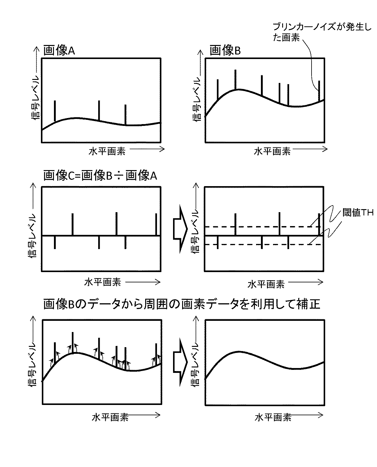
続いて、図5を用いて、本実施形態によるブリンカーノイズ発生画素の抽出及び補正方法について説明する。図5は、図4の読み出し動作を簡略化して書いたものである。本実施形態では、放射線の照射中に1回画像を読み出し、放射線照射終了後に再度読み出しを行い、1回の放射線照射で2フレームの画像を取得した場合の処理について説明する。 Next, a method for extracting and correcting blinker noise occurrence pixels according to the present embodiment will be described with reference to FIG. FIG. 5 is a simplified illustration of the read operation of FIG. In the present embodiment, a process will be described in which an image is read once during irradiation of radiation, read out again after the end of irradiation, and two frames of images are acquired by one irradiation of radiation.
図5では、放射線照射期間をt1+t2とし、放射線照射中の1回目の読み出しにより、放射線が期間t1照射された画像を画像Aとして読み出し、画像Aがコンピュータ108のフレームメモリ115に蓄積される。そして、放射線が全て照射された後に最後の読み出しを行い、放射線が期間t1+t2照射された画像として画像Bを読み出し、画像Bがフレームメモリ115に蓄積される。このとき、ブリンカーノイズは、放射線照射中にランダムな時間・場所で発生する。すなわち、画像Aには期間t1で発生したブリンカーノイズが重畳し、画像Bには期間t1+t2で発生したブリンカーノイズ(=放射線照射で発生したすべてのブリンカーノイズ)が重畳している。そこで、コンピュータ(抽出部)108は、例えば、複数の画素S11〜Smnから出力された出力信号に基づく画像を基に、次式のような除算を用いた演算処理をする。これにより、蛍光体101を透過して画素S11〜Smnに到達した放射線によって生じるノイズが発生した画素を抽出する。
画像C=画像B/画像A
In FIG. 5, the irradiation period is t1 + t2, and an image irradiated with the period t1 is read as an image A by the first reading during the irradiation, and the image A is stored in the
Image C = Image B / Image A
画像Aと画像Bは異なる放射線強度で同じ被写体を撮影したものであり、これらを除算した商となる画像Cのうち、ブリンカーノイズが重畳していない画素値は全ての画素値がある一定の値となり、被写体の情報が除去された画像となる。ブリンカーノイズの重畳した画素は、画素値が通常の画素と異なるようになり、両者の区別が可能となる。 The image A and the image B are obtained by photographing the same subject with different radiation intensities. Among the images C obtained by dividing these images, the pixel values on which no blinker noise is superimposed are all constant values. Thus, an image from which the subject information is removed is obtained. A pixel on which blinker noise is superimposed has a pixel value different from that of a normal pixel, and can be distinguished from each other.
以下、除算を用いた演算処理でブリンカーノイズの発生した画素を抽出する原理について、図6を用いて説明する。図6は、横軸に放射線の照射時間、縦軸に画素の信号レベルをとったもので、放射線が0からt2までの時間に放射線が当たった時の撮像素子102のある4点の画素(画素A、画素B、画素C、画素D)の信号レベルの変化を示している。ここで、4点の画素の信号レベルの上昇の傾きが異なっているのは、被写体の影響であり放射線の透過しやすい部分は傾きが大きく、放射線の透過しにくい部分は傾きが小さくなる。また、画素Aと画素Bは、ブリンカーノイズが発生していない画素で、画素Cと画素Dは、それぞれ時刻tn1及びtn2にブリンカーノイズが発生し、信号レベルが大きくなっていることを示している。本実施形態では、放射線照射中の任意の時間に1回読み出しを行い、放射線照射後に再度読み出しを行うため、時刻t1に最初1回目の読み出しを行い、時刻t2に放射線の照射を終了し、最後の読み出しを行う。
Hereinafter, the principle of extracting pixels in which blinker noise has occurred in arithmetic processing using division will be described with reference to FIG. In FIG. 6, the horizontal axis represents the irradiation time of the radiation, and the vertical axis represents the pixel signal level. The four pixels (with the
本実施形態では、時刻t1に取得した画像Aと時刻t2に取得した画像Bの割り算を行い、ブリンカーノイズの発生した画素を抽出する。これは、つまり2枚の画像の信号レベルの比を取ることに等しい。時刻t1での画素Aの信号レベルをat1、画素Bの信号レベルをbt1、時刻t2での画素Aの信号レベルをat2、画素Bの信号レベルをbt2とすると、2枚の画像の信号レベルの比は、画素Aではat1/at2、画素Bではbt1/bt2となる。また、図6より、三角形の相似の関係から、次式のようになる。
at1:at2=bt1:bt2
at1/at2=bt1/bt2
In this embodiment, the image A acquired at time t1 and the image B acquired at time t2 are divided to extract pixels where blinker noise has occurred. This is equivalent to taking the ratio of the signal levels of the two images. If the signal level of pixel A at time t1 is at1, the signal level of pixel B is bt1, the signal level of pixel A at time t2 is at2, and the signal level of pixel B is bt2, the signal levels of the two images The ratio is at1 / at2 for pixel A and bt1 / bt2 for pixel B. Further, from FIG. 6, the following equation is obtained from the similar relation of triangles.
at1: at2 = bt1: bt2
at1 / at2 = bt1 / bt2
これは、つまり2枚の画像A及びBを、除算を用いて演算することで、画像から被写体の情報が除去できるということを示している。また、時刻t1は時刻0〜t2の間の任意の時刻であり、この時刻が変化しても、前述した関係は変わらない。以上のことから、ブリンカーノイズが発生していない画素A及びBにおいては、先述した実施形態で得られる2枚の画像A及びBを除算を用いて演算処理することで画素値がある値で一定となり、被写体情報を除去できる。
This indicates that the subject information can be removed from the images by calculating the two images A and B using division. The time t1 is an arbitrary time between
続いて、ブリンカーノイズが発生した画素の場合を述べる。図示していないが、ブリンカーノイズが発生した画素である画素Cの時刻t1での信号レベルをct1、時刻t2での信号レベルをct2とすると、次式のようになる。
at1:at2≠ct1:ct2
at1/at2≠ct1/ct2
Next, the case of a pixel in which blinker noise has occurred will be described. Although not shown, when the signal level at the time t1 of the pixel C, which is the pixel where the blinker noise occurs, is ct1, and the signal level at the time t2 is ct2, the following equation is obtained.
at1: at2 ≠ ct1: ct2
at1 / at2 ≠ ct1 / ct2
つまり、ブリンカーノイズが発生した画素Cはノイズが発生していない通常の画素Aの画素値とは異なることを示している。また、ブリンカーノイズの発生時刻が違う画素Dについても、時刻t1での信号レベルをdt1、時刻t2での信号レベルをdt2とすると、次式のようになり、通常画素Aの画素値とは異なる。
at1/at2≠dt1/dt2
That is, the pixel C in which blinker noise has occurred is different from the pixel value of a normal pixel A in which noise has not occurred. Also, regarding the pixel D having a different blinker noise generation time, if the signal level at time t1 is dt1, and the signal level at time t2 is dt2, the following equation is obtained, which is different from the pixel value of the normal pixel A: .
at1 / at2 ≠ dt1 / dt2
前述した駆動で読み出し動作を行い、2枚の画像A及びBを取得した後に、2枚の画像A及びBの除算の演算処理をすることで、ブリンカーノイズが発生していない通常の画素はある値で一定となる。これにより、ブリンカーノイズが発生した画素は通常の画素とは異なる値となり、両者の区別ができることになる。 There is a normal pixel that does not generate blinker noise by performing a read operation with the drive described above and obtaining two images A and B, and then performing a division operation on the two images A and B. The value is constant. As a result, the pixel in which blinker noise occurs has a value different from that of a normal pixel, and the two can be distinguished.
なお、ブリンカーノイズの発生した画素を全て抽出するための必要条件は、全てのブリンカーノイズが、除算する画像のいずれかに入っていることである。本実施形態の場合では、画像Bに全てのブリンカーノイズが重畳しているため、この条件を満たしている。 Note that a necessary condition for extracting all pixels in which blinker noise has occurred is that all blinker noise is included in one of the images to be divided. In the case of this embodiment, since all blinker noises are superimposed on the image B, this condition is satisfied.
図7の上段は、上記動作で得られた画像A及び画像Bのある行の画素値を示し、被写体画像に所々ブリンカーノイズが重畳して信号レベルが高くなっていることを示している。また、図7の中段及び下段では、その後の処理の過程を示している。図7の中段では、画像Cは画像B/画像Aをしたものを示したものであり、ブリンカーノイズが重畳していない画素は一定の値になるが、ブリンカーノイズが重畳した画素は通常の画素と異なる値となることがわかる。このような演算処理をした画像Cに、例えば、次式のような閾値THを設け、閾値THを超えた画素の座標をブリンカーノイズが重畳した画素として座標を抽出する。
閾値TH=(画像Cの平均値)±(画像Cの平均値×10%)
The upper part of FIG. 7 shows the pixel values of a certain row of the image A and the image B obtained by the above operation, and shows that the signal level is increased by overlapping the blinker noise in some places in the subject image. Further, the middle stage and the lower stage in FIG. In the middle part of FIG. 7, the image C shows the image B / image A, and the pixels where the blinker noise is not superimposed have a constant value, but the pixels where the blinker noise is superimposed are normal pixels. It turns out that it becomes a different value. For example, a threshold TH as shown in the following equation is provided in the image C that has been subjected to such arithmetic processing, and the coordinates of a pixel that exceeds the threshold TH are extracted as pixels on which blinker noise is superimposed.
Threshold TH = (average value of image C) ± (average value of image C × 10%)
なお、上記の%値は、通常3〜20%程度の値をとる。この閾値THは要求品質で決定され、撮像素子102のバラつきによる誤差の許容範囲と同等の許容範囲で閾値を設定することが好ましい。通常、撮像素子102には線形性等のバラつきがあり、一定の範囲内で誤差が許容されている。例えば、撮像素子102のバラつきによる誤差を10%の範囲で許容した場合、除算処理した画像Cのうちブリンカーノイズが重畳していない通常の画素値には最大10%の誤差があると考えられる。そこで、ブリンカーノイズの閾値設定でも、これと同等の誤差は許容するように設定するのが好ましい。なお、平均値からプラス方向の閾値とマイナス方向の閾値で異なっていても良い。また、上記では、閾値の設定に画像平均値を利用したが、例えば画像Cの標準偏差の5倍と規定しても良い。また、画像の出力値から閾値の設定値を自動的に変化させるようにしても良い。いずれであっても、ブリンカーノイズが診断画像に認識されないようにするべきである。
In addition, said% value takes the value of about 3 to 20% normally. This threshold TH is determined by the required quality, and it is preferable to set the threshold within an allowable range equivalent to the allowable range of error due to variations in the
以上のように、コンピュータ(抽出部)108は、変換部101に放射線が照射される放射線照射期間のうちの第1の期間t1に変換部101に照射された放射線に応じて複数の画素S11〜Smnから出力された出力信号に基づく第1の画像Aを取得する。そして、コンピュータ(抽出部)108は、放射線照射期間のうちの第1の期間t1の後の第2の期間t2に変換部101に照射された放射線に応じて複数の画素S11〜Smnから出力された出力信号に基づく第2の画像Bを取得する。そして、コンピュータ(抽出部)108は、第1の画像Aと第2の画像Bとを除算することにより、ノイズが発生した画素を抽出する。
As described above, the computer (extraction unit) 108 includes a plurality of pixels S11 to S11 according to the radiation irradiated to the
コンピュータ(補正部)108は、ノイズが生じた画素の抽出を終えた後、図7の下段のように、画像Bからノイズ座標として抽出した画素から出力された出力信号に対して、ノイズを除去するための補正を行う。例えば、ブリンカーノイズが重畳した画素として抽出された座標の画素の元の画素値を一旦破棄し、隣接画素の平均値をその画素値とすることで補正を行う。以上のように、本実施形態によれば、ノイズの少ない良質な画像が得られる。 The computer (correction unit) 108 removes noise from the output signal output from the pixel extracted as the noise coordinate from the image B as shown in the lower part of FIG. To make corrections. For example, the correction is performed by once discarding the original pixel value of the pixel at the coordinate extracted as the pixel on which blinker noise is superimposed, and using the average value of the adjacent pixels as the pixel value. As described above, according to the present embodiment, a high-quality image with less noise can be obtained.
(第2の実施形態)
本発明の第2の実施形態による撮像装置は、図1、図2及び図3に示した第1の実施形態の構成と同様であり、詳細な説明は割愛する。本実施形態が第1の実施形態と異なる点は、放射線照射中に2回以上、照射後に1回以上の読み出し動作を行い、3枚以上の画像を取得した時の処理方法である。
(Second Embodiment)
The imaging apparatus according to the second embodiment of the present invention is the same as the configuration of the first embodiment shown in FIGS. 1, 2, and 3, and will not be described in detail. This embodiment is different from the first embodiment in a processing method when three or more images are acquired by performing a reading operation twice or more during irradiation and once or more after irradiation.
図8は、1回の放射線照射で画像を3回読み出しを行った時の、読み出し動作を簡略化して書いたものである。図8では、放射線照射期間をt1+t2+t3とし、放射線照射中の1回目の読み出しにより、期間t1の放射線照射で発生した電荷の画像を画像Dとして読み出す。次に、放射線照射中の2回目の読み出しにより、期間t1+t2の放射線照射で発生した電荷の画像を画像Eとして読み出す。最後に、放射線が全て照射された後に、最後の読み出しにより、期間t1+t2+t3の放射線照射で発生した電荷の画像として画像Fを読み出し、画像D,E,Fをフレームメモリ115に蓄積する。
FIG. 8 shows a simplified read operation when an image is read three times by one irradiation. In FIG. 8, the radiation irradiation period is t1 + t2 + t3, and an image of charges generated by the radiation irradiation in the period t1 is read as an image D by the first reading during the radiation irradiation. Next, an image of charges generated by radiation irradiation in the period t1 + t2 is read as an image E by the second reading during radiation irradiation. Finally, after all the radiation is irradiated, the image F is read as an image of the charges generated by the radiation irradiation in the period t1 + t2 + t3 by the last reading, and the images D, E, and F are stored in the
次に、図9を用いて、ブリンカーノイズが発生した画素を抽出する方法を説明する。図9は、画像D、画像E及び画像Fのある行の画素値で示したものであり、本実施形態で読み出した画像及びそれを用いてブリンカーノイズが発生した画素を抽出する方法を示している。本実施形態では、例えば、次式のような除算を用いた演算処理により、画像X及びYを求め、ノイズが発生した画素を抽出する。
画像X=画像D/画像F
画像Y=画像E/画像F
Next, a method for extracting pixels in which blinker noise has occurred will be described with reference to FIG. FIG. 9 shows pixel values in a row of the image D, the image E, and the image F, and shows an image read out in the present embodiment and a method for extracting pixels in which blinker noise has occurred using the image. Yes. In the present embodiment, for example, the images X and Y are obtained by arithmetic processing using division such as the following equation, and the pixel in which noise occurs is extracted.
Image X = Image D / Image F
Image Y = Image E / Image F
本実施形態においても、第1の実施形態と同様に、画像X及び画像Yはブリンカーノイズが重畳していない通常の画素は全ての画素がある一定の値となり、ブリンカーノイズの重畳した画素は演算後の画素値が通常の画素値と異なる値を取る。本実施形態では、第1の実施形態と同様に、例えば、次式のような閾値THx及びTHyを設け、画像X及びYにおいて、それぞれ閾値Tx及びTyを超えた画素の座標をブリンカーノイズが重畳した画素として座標を抽出する。閾値の好ましい設定値に関しては、第1の実施形態と同様であり、詳細は割愛する。 Also in the present embodiment, as in the first embodiment, in the image X and the image Y, the normal pixels on which blinker noise is not superimposed all have a certain value, and the pixels on which blinker noise is superimposed are calculated. The subsequent pixel value is different from the normal pixel value. In the present embodiment, as in the first embodiment, for example, threshold values THx and THy as shown in the following formula are provided, and in the images X and Y, the coordinates of pixels exceeding the threshold values Tx and Ty are superimposed with blinker noise, respectively. The coordinates are extracted as the obtained pixels. The preferable setting value of the threshold is the same as that of the first embodiment, and details are omitted.
閾値THx=(画像Xの平均値)±(画像Xの平均値×10%)
閾値THy=(画像Yの平均値)±(画像Yの平均値×10%)
Threshold THx = (average value of image X) ± (average value of image X × 10%)
Threshold THy = (average value of image Y) ± (average value of image Y × 10%)
さらに、画像Xからの抽出座標と画像Yからの抽出座標の論理積をとり、その論理積値が1である座標をブリンカーノイズが発生した画素の座標とする。このように取得した3枚以上の画像から2枚以上の演算処理画像を作成してブリンカーノイズが発生した画素の座標を抽出し、その抽出座標の論理積又は論理和を取る。これにより、ブリンカーノイズ以外のノイズ成分による座標抽出誤差を低減させることができ、ブリンカーノイズが発生した画素座標の抽出精度を上げることができる。 Further, the logical product of the extracted coordinates from the image X and the extracted coordinates from the image Y is calculated, and the coordinate having the logical product value of 1 is set as the coordinate of the pixel in which blinker noise occurs. Two or more arithmetic processing images are created from the three or more images acquired in this way, and the coordinates of the pixel where blinker noise occurs are extracted, and a logical product or a logical sum of the extracted coordinates is obtained. Thereby, it is possible to reduce coordinate extraction errors due to noise components other than blinker noise, and it is possible to improve the extraction accuracy of pixel coordinates where blinker noise has occurred.
なお、ブリンカーノイズが発生した画素を抽出するための計算式は、本実施形態の方法以外にも多数あり、全てのブリンカーノイズが発生した画素を抽出するために必要な条件は、全てのブリンカーノイズが、除算する画像のいずれかに入っていることである。 There are many calculation formulas for extracting pixels where blinker noise has occurred in addition to the method of the present embodiment, and the conditions necessary for extracting all pixels where blinker noise has occurred are all the blinker noises. Is in one of the images to be divided.
以上のように、コンピュータ(抽出部)108は、変換部101に放射線が照射される放射線照射期間のうちの第1の期間t1に変換部101に照射された放射線に応じて複数の画素S11〜Smnから出力された出力信号に基づく第1の画像Dを取得する。そして、コンピュータ(抽出部)108は、放射線照射期間のうちの第1の期間t1の後かつ第2の期間t3の前の第3の期間t2に変換部101に照射された放射線に応じて複数の画素S11〜Smnから出力された出力信号に基づく第3の画像Eを取得する。そして、コンピュータ(抽出部)108は、放射線照射期間のうちの第3の期間t2の後の第2の期間t3に変換部101に照射された放射線に応じて複数の画素S11〜Smnから出力された出力信号に基づく第2の画像Fを取得する。そして、コンピュータ(抽出部)108は、第1の画像Dと第2の画像Fとを除算し、第3の画像Eと第2の画像Fとを除算する。そして、コンピュータ(抽出部)108は、第1の画像D及び第2の画像Fの除算結果画像Xと第3の画像Eと第2の画像Fの除算結果画像Yを用いた論理演算を行うことにより、ノイズが発生した画素を抽出する。
As described above, the computer (extraction unit) 108 includes a plurality of pixels S11 to S11 according to the radiation irradiated to the
(第3の実施形態)
本発明の第3の実施形態では、読み出し処理後に画素内に電気信号を残さない方法で読み出しを行う方法及びこの方法で読み出しを行った場合の演算処理方法について、図10、図11、図12を用いて説明する。第1の実施形態(図4及び図5)では、リセットトランジスタM1は、第1の期間t1の放射線に応じた第1の画像Aが出力された後かつ第2の期間t2の放射線に応じた第2の画像Bが出力される前に、複数の画素S11〜Smnをリセットしない。また、第2の実施形態(図8)では、リセットトランジスタM1は、第1の期間t1の放射線に応じた第1の画像Dが出力された後かつ第2の期間t3の放射線に応じた第2の画像Fが出力される前に、複数の画素S11〜Smnをリセットしない。これに対し、第3の実施形態(図10及び図11)では、リセットトランジスタM1は、第1の期間t1の放射線に応じた第1の画像Gが出力された後かつ第2の期間t2の放射線に応じた第2の画像Hが出力される前に、複数の画素S11〜Smnをリセットする。なお、第3の実施形態に係る撮像装置は、図1、図2及び図3の第1及び第2の実施形態の構成と同様であり、詳細な説明は割愛する。
(Third embodiment)
In the third embodiment of the present invention, a method of performing readout by a method that does not leave an electrical signal in a pixel after readout processing and an arithmetic processing method in the case of performing readout by this method will be described with reference to FIGS. Will be described. In the first embodiment (FIGS. 4 and 5), the reset transistor M1 responds to the radiation in the second period t2 after the first image A corresponding to the radiation in the first period t1 is output. The plurality of pixels S11 to Smn are not reset before the second image B is output. Further, in the second embodiment (FIG. 8), the reset transistor M1 outputs the first image D corresponding to the radiation in the first period t1 and outputs the first image D corresponding to the radiation in the second period t3. The plurality of pixels S11 to Smn are not reset before the second image F is output. On the other hand, in the third embodiment (FIGS. 10 and 11), the reset transistor M1 is output after the first image G corresponding to the radiation in the first period t1 is output and in the second period t2. Before the second image H corresponding to the radiation is output, the plurality of pixels S11 to Smn are reset. Note that the imaging apparatus according to the third embodiment is the same as the configuration of the first and second embodiments of FIGS. 1, 2, and 3, and a detailed description thereof is omitted.
以下、図10を用いて、第3の実施形態の撮像装置100における読み出し動作について、第1の実施形態と異なる点を説明する。図10において、XRAYのハイレベルは放射線の照射時間を示す。RESは図3のリセット線RES1〜RESmのリセットパルスを示す。TXは図3の転送選択線TX1〜TXmの転送パルスを示す。SEL1〜SELnは、行選択線SEL1〜SELnの行選択パルスを示す。
Hereinafter, with reference to FIG. 10, a different point from the first embodiment regarding the reading operation in the
図10における期間t1が終了するまでは第1の実施形態と同様であり、まず、放射線照射中に1回目の読み出しを行う。1回目の読み出しで生成される画像は、期間t1の放射線照射で発生した電荷の画像となる。 The process is the same as in the first embodiment until the period t1 in FIG. 10 ends. First, the first reading is performed during radiation irradiation. An image generated by the first reading is an image of charges generated by radiation irradiation in the period t1.
次に、1回目の読み出し終了後の放射線照射中に、一度、リセットパルスRESをハイレベルにし、コンデンサCgの電荷をリセットする。続いて、放射線の照射が終了した後に、全画素一斉の転送パルスTXをハイレベルにし、図10の期間t2の放射線照射で発生した電荷がフォトダイオードPDからコンデンサCgに転送される。コンデンサCgには、期間t2の放射線照射で発生した電荷が転送されることになる。その後、第1の実施形態と同様に、最後の読み出しを行う。第3の実施形態では、最後の読み出しで生成される画像は、期間t2の放射線照射で発生した電荷の画像となる。 Next, during the radiation irradiation after the completion of the first reading, the reset pulse RES is once set to the high level to reset the charge of the capacitor Cg. Subsequently, after the radiation irradiation is completed, the transfer pulse TX for all the pixels is set to the high level, and the charge generated by the radiation irradiation in the period t2 in FIG. 10 is transferred from the photodiode PD to the capacitor Cg. Charges generated by radiation irradiation during the period t2 are transferred to the capacitor Cg. Thereafter, the last reading is performed as in the first embodiment. In the third embodiment, the image generated by the last readout is an image of charges generated by radiation irradiation in the period t2.
なお、1回目の読み出しが終了した後、最後の読み出しが始まる前までの放射線照射期間中に、さらに1回以上の読み出し動作を行い、計3枚以上の画像を取得しても良い。また、放射線の照射条件や撮影条件などから最適な撮影枚数を自動的に計算しても良いことは、第1の実施形態と同じである。 Note that a total of three or more images may be acquired by performing one or more reading operations during the radiation irradiation period after the completion of the first reading and before the start of the last reading. Further, as in the first embodiment, the optimum number of shots may be automatically calculated based on radiation irradiation conditions and imaging conditions.
続いて、図11を用いて、第3の実施形態におけるブリンカーノイズ発生画素の補正方法について、第1の実施形態と異なる点を説明する。図11は、読み出し動作を簡略化して書いたものである。本実施形態では、放射線の照射中に1回画像を読み出し、放射線照射終了後に再度読み出しを行い、1回の放射線照射で2フレームの画像を取得した場合の処理について説明する。第3の実施形態では、放射線照射中に1回目の読み出しにより、放射線が期間t1照射された画像を画像Gとして読み出し、コンピュータ108のフレームメモリ115に蓄積する。そして、放射線が全て照射された後に最後の読み出しを行い、放射線が期間t2照射された画像を画像Hとして読み出し、フレームメモリ115に蓄積する。
Next, the difference between the blinker noise occurrence pixel correction method in the third embodiment and the first embodiment will be described with reference to FIG. FIG. 11 shows a simplified read operation. In the present embodiment, a process will be described in which an image is read once during irradiation of radiation, read out again after the end of irradiation, and two frames of images are acquired by one irradiation of radiation. In the third embodiment, an image on which radiation is irradiated for a period t1 is read as an image G by the first reading during radiation irradiation, and is stored in the
このとき、ブリンカーノイズは放射線照射中にランダムな時間・場所で発生するため、画像Gには期間t1で発生したブリンカーノイズが重畳し、画像Hには期間t2で発生したブリンカーノイズが重畳している。そこで、本実施形態では、例えば、次式のような除算を用いた演算処理することで、画像Zを求め、ノイズが発生した画素を抽出する。
画像Z=画像H/画像G
At this time, since blinker noise is generated at random times and places during radiation irradiation, blinker noise generated in period t1 is superimposed on image G, and blinker noise generated in period t2 is superimposed on image H. Yes. Therefore, in the present embodiment, for example, an image Z is obtained by performing arithmetic processing using division such as the following equation, and a pixel in which noise occurs is extracted.
Image Z = Image H / Image G
第1の実施形態と同様に、画像Zではブリンカーノイズが重畳していない画素は全ての画素がある一定の値となり、被写体の情報が除去された画像となる。ブリンカーノイズの重畳した画素は、画素値が通常の画素値と異なるようになり、両者の区別が可能となる。なお、ブリンカーノイズが発生した画素を全て抽出するための必要条件は、第1の実施形態と同様に、全てのブリンカーノイズが、除算する画像のいずれかに入っていることである。 As in the first embodiment, in the image Z, pixels on which blinker noise is not superimposed have an image with all pixels having a certain value, and the subject information is removed. A pixel on which blinker noise is superimposed has a pixel value different from a normal pixel value, and thus can be distinguished from each other. Note that a necessary condition for extracting all pixels in which blinker noise has occurred is that all blinker noise is included in one of the images to be divided, as in the first embodiment.
第3の実施形態では、ブリンカーノイズが期間t1+t2ですべて発生しており、画像Gには期間t1で発生したブリンカーノイズが、画像Hには期間t2で発生したブリンカーノイズがそれぞれ重畳しているため、上記の条件を満たしている。 In the third embodiment, all blinker noise is generated in the period t1 + t2, the blinker noise generated in the period t1 is superimposed on the image G, and the blinker noise generated in the period t2 is superimposed on the image H. The above conditions are met.
図12の上段は、画像G及び画像Hのある行の画素値を示し、被写体画像の所々にブリンカーノイズが重畳して信号レベルが高くなっていることを示している。図12の中段及び下段では、その後の処理の過程を示している。図12の中段では、画像Zは画像H/画像Gの演算を行ったものであり、ブリンカーノイズが重畳していない画素は一定の値になるが、ブリンカーノイズが重畳した画素は通常の画素と異なる値となることがわかる。このような演算処理をした画像Zに、例えば、次式のような閾値THzを設け、閾値THzを超えた画素の座標をブリンカーノイズが重畳した画素として座標を抽出する。閾値の好ましい設定値に関しては、第1の実施形態と同様であり、詳細は割愛する。
閾値THz=(画像Zの平均値)±(画像Zの平均値×10%)
The upper part of FIG. 12 shows the pixel values of a row of the image G and the image H, and shows that the signal level is increased due to the blinker noise being superimposed on the subject image. The middle stage and the lower stage of FIG. 12 show the subsequent process. In the middle part of FIG. 12, the image Z is obtained by performing the calculation of the image H / image G, and pixels where the blinker noise is not superimposed have a constant value, but the pixels where the blinker noise is superimposed are normal pixels. It can be seen that the values are different. For example, a threshold value THz as shown in the following equation is provided in the image Z that has been subjected to such calculation processing, and the coordinates of a pixel that exceeds the threshold value THz are extracted as pixels on which blinker noise is superimposed. The preferable setting value of the threshold is the same as that of the first embodiment, and details are omitted.
Threshold value THz = (average value of image Z) ± (average value of image Z × 10%)
続いて、抽出した座標情報からブリンカーノイズを除去するための補正を行う。第3の実施形態では、画像Gは期間t1の放射線照射で発生した電荷の画像であり、画像Hは期間t2の放射線照射で発生した電荷の画像であり、期間t1+t2の放射線照射で発生した電荷の画像は取得していない。このため、次式により、画像Jを求める。
画像J=画像G+画像H
Subsequently, correction for removing blinker noise from the extracted coordinate information is performed. In the third embodiment, the image G is an image of charges generated by radiation irradiation in the period t1, and the image H is an image of charges generated by radiation irradiation in the period t2, and the charges generated by radiation irradiation in the period t1 + t2. No images were acquired. For this reason, the image J is obtained by the following equation.
Image J = Image G + Image H
画像Jは期間t1+t2の放射線照射で発生した電荷の画像となり、画像Jを用いてブリンカーノイズを除去するための補正を行う。ブリンカーノイズが重畳した画素として抽出された座標の画素は、画像Jの元の画素値を一旦破棄し、例えば隣接画素の平均値をその画素値とすることで補正を行う。 The image J becomes an image of charges generated by radiation irradiation in the period t1 + t2, and correction for removing blinker noise is performed using the image J. The pixel of the coordinate extracted as the pixel on which the blinker noise is superimposed is corrected by temporarily discarding the original pixel value of the image J and using, for example, the average value of adjacent pixels as the pixel value.
次に、ノイズが発生した画素を抽出する他の方法を説明する。放射線照射中に取得した画像をm1、m2、m3・・・mn-1、放射線照射終了後に取得した画像をmn(nは整数)としたときに、次式(1)の演算により複数の第5の画像を取得する。すなわち、コンピュータ(抽出部)108は、第1の画像m1、m2、m3・・・mn-1及び第2の画像mnを加算することにより第4の画像を取得する。そして、第1の画像m1、m2、m3・・・mn-1及び第4の画像の除算結果並びに第2の画像mn及び第4の画像の除算結果を用いて式(1)の複数の第5の画像を取得する。 Next, another method for extracting pixels in which noise has occurred will be described. When an image acquired during radiation irradiation is m 1 , m 2 , m 3 ... M n-1 , and an image acquired after the radiation irradiation is finished is m n (n is an integer), the following equation (1) A plurality of fifth images are obtained by calculation. That is, the computer (extraction unit) 108 acquires the fourth image by adding the first images m 1 , m 2 , m 3 ... Mn−1 and the second image mn . Then, using the division result of the first image m 1 , m 2 , m 3 ... Mn−1 and the fourth image and the division result of the second image mn and the fourth image, the expression (1 A plurality of fifth images are acquired.
その後、式(1)により取得した複数の画像に対して、第2の実施形態(図9)と同様に、閾値THx及びTHy等を用いて、ノイズが発生した画像を抽出する。その後の補正方法は、第2の実施形態と同様である。すなわち、抽出部は、式(1)の複数の第5の画像の論理演算(論理積又は論理和)を行い、ノイズが発生した画素を抽出する。 Thereafter, as in the second embodiment (FIG. 9), images with noise are extracted from the plurality of images acquired by Expression (1) using threshold values THx and THy. The subsequent correction method is the same as in the second embodiment. In other words, the extraction unit performs a logical operation (logical product or logical sum) of the plurality of fifth images in Expression (1), and extracts pixels in which noise has occurred.
(第4の実施形態)
第2の実施形態に示すように、放射線照射期間に画像を取得する回数を増やすことで、ブリンカーノイズが発生した画素の抽出精度を上げることができる。しかし、読み出し動作に必要な時間は決まっているため、例えば放射線の照射時間が短ければ、画像の取得回数をむやみに多くすることはできない。放射線の照射時間が長ければ画像の取得回数を多くすることはできる。しかし、むやみに多くすると消費電力が増大し、発熱による誤作動などの可能性が高くなり、バッテリで駆動するタイプの撮像装置の場合では総撮影枚数の低下の可能性があり、画像の取得回数には限度がある。
(Fourth embodiment)
As shown in the second embodiment, by increasing the number of times an image is acquired during the radiation irradiation period, it is possible to increase the extraction accuracy of pixels in which blinker noise has occurred. However, since the time required for the read operation is determined, for example, if the irradiation time of radiation is short, the number of image acquisitions cannot be increased excessively. If the irradiation time of radiation is long, the number of times of image acquisition can be increased. However, excessively increasing the power consumption increases the possibility of malfunction due to heat generation, etc., and in the case of an imaging device driven by a battery, the total number of shots may decrease, and the number of image acquisitions Has a limit.
さらに、放射線の強度とブリンカーノイズの発生確率には関係性があり、例えば、放射線源111の管電圧が高いとブリンカーノイズの発生確率が低いことが分かっている。そこで、本発明の第4の実施形態では、これらの情報から放射線照射中の画像の取得回数を自動的に規定する方法について、図1を用いて説明する。
Furthermore, there is a relationship between the intensity of radiation and the occurrence probability of blinker noise. For example, it is known that the occurrence probability of blinker noise is low when the tube voltage of the
制御卓113では、放射線源111の撮像条件(放射線の管電圧、管電流)、放射線の照射条件(照射時間)及び/又は消費電力などの情報が操作者から入力され、コンピュータ108にそれらの情報が出力される。コンピュータ108は、これらの情報に基づき、撮像条件の情報からブリンカーノイズが発生した画素を完全に抽出するために必要とされる撮影枚数を、放射線の照射条件の情報から撮影可能枚数を、消費電力等の関係から決定される撮影限界枚数を算出する。そして、コンピュータ108は、それらを比較して、最も少ない枚数を放射線照射中の画像の取得回数として決定する。その後、コンピュータ108は、放射線制御装置109と撮像装置100を同期し、曝射要求信号を放射線制御装置109に出力し、撮像装置100の動作を決定する制御信号を出力し、動作を開始させる。放射線照射中、照射後の駆動及びノイズ画素座標抽出のための演算手段、ノイズ補正手段に関しては、第1〜第3の実施形態と同様である。
In the
第1〜第4の実施形態によれば、簡単な処理で、ブリンカーノイズを抽出して除去することができ、診断能力を向上させることができる。また、特殊な機構・部材を必要とせずにノイズの除去が行えるため、コストの上昇を抑制することができる。 According to the first to fourth embodiments, blinker noise can be extracted and removed with a simple process, and diagnostic ability can be improved. Further, since noise can be removed without requiring a special mechanism / member, an increase in cost can be suppressed.
なお、上記実施形態は、何れも本発明を実施するにあたっての具体化の例を示したものに過ぎず、これらによって本発明の技術的範囲が限定的に解釈されてはならないものである。すなわち、本発明はその技術思想、又はその主要な特徴から逸脱することなく、様々な形で実施することができる。 The above-described embodiments are merely examples of implementation in carrying out the present invention, and the technical scope of the present invention should not be construed in a limited manner. That is, the present invention can be implemented in various forms without departing from the technical idea or the main features thereof.
100 撮像装置、101 蛍光体、108 コンピュータ、109 放射線制御装置、110 放射線発生装置、S11〜Smn 画素
DESCRIPTION OF
Claims (18)
前記変換部によって変換された光を電気信号に変換する複数の画素と、
前記複数の画素から読み出された信号に基づく画像を基に、前記変換部を透過して前記画素に到達した放射線によって生じるノイズが発生した画素を抽出する抽出部と、
前記抽出部により抽出された画素から読み出された信号に対して、前記ノイズを除去するための補正を行う補正部とを有し、
前記抽出部は、前記変換部に放射線が照射される放射線照射期間のうちの第1の期間に前記変換部に照射された放射線に応じて前記複数の画素から読み出された信号に基づく第1の画像と前記放射線照射期間のうちの前記第1の期間の後の第2の期間に前記変換部に照射された放射線に応じて前記複数の画素から読み出された信号に基づく第2の画像とを除算し、さらに、前記放射線照射期間のうちの前記第1の期間の後かつ前記第2の期間の前の第3の期間に前記変換部に照射された放射線に応じて前記複数の画素から読み出された信号に基づく第3の画像と前記第2の画像とを除算し、前記第1の画像及び前記第2の画像の除算結果と前記第3の画像と前記第2の画像の除算結果を用いた論理演算を行うことにより、前記ノイズが発生した画素を抽出することを特徴とする撮像システム。 A converter that converts radiation into light;
A plurality of pixels for converting the light converted by the converter into an electrical signal;
An extraction unit that extracts based on an image based on the signal that is read out from said plurality of pixels, the pixel noise is generated caused by radiation which reaches the pixel is transmitted through the converting unit,
Relative signal which is read out from the pixels extracted by the extraction unit, and a correcting unit for correcting for removing the noise,
The extraction section, first based on a signal that is read out from said plurality of pixels in accordance with the radiation applied to the conversion unit to the first period of the irradiation period the radiation is irradiated to the conversion unit the based on signals which are read out from said plurality of pixels in accordance with the radiation applied to the conversion unit during a second period after the first period of the first image and the previous SL irradiation period The image is divided by two, and further according to the radiation irradiated to the conversion unit in the third period after the first period and before the second period of the radiation irradiation period. A third image based on signals read from a plurality of pixels and the second image are divided, the division result of the first image and the second image, the third image, and the second image by performing a logical operation using the division result of the image, the noise is generated Imaging system and extracting the pixels.
前記リセット部は、前記第1の期間に照射された放射線に応じた信号が前記複数の画素から読み出された後かつ前記第2の期間に照射された放射線に応じた信号が前記複数の画素から読み出される前に、前記複数の画素をリセットしないことを特徴とする請求項1記載の撮像システム。 And a reset unit that resets electrical signals accumulated in the plurality of pixels.
The reset unit, the first signal is a plurality representative of the radiation which signals representative of the radiation emitted is irradiated on and the second period after being read out from said plurality of pixels in the period the imaging system of claim 1, wherein the prior to being read out from the pixels, characterized in that it does not reset the plurality of pixels.
前記リセット部は、前記第1の期間に照射された放射線に応じた信号が前記複数の画素から読み出された後かつ前記第2の期間に照射された放射線に応じた信号が前記複数の画素から読み出される前に、前記複数の画素をリセットすることを特徴とする請求項1記載の撮像システム。 And a reset unit that resets electrical signals accumulated in the plurality of pixels.
The reset unit, the first signal is a plurality representative of the radiation which signals representative of the radiation emitted is irradiated on and the second period after being read out from said plurality of pixels in the period the imaging system of claim 1, wherein the prior to being read out from the pixels, characterized by resetting the plurality of pixels.
前記変換部によって変換された光を電気信号に変換する複数の画素と、A plurality of pixels for converting the light converted by the converter into an electrical signal;
前記複数の画素から読み出された信号に基づく画像を基に、前記変換部を透過して前記画素に到達した放射線によって生じるノイズが発生した画素を抽出する抽出部と、Based on an image based on signals read from the plurality of pixels, an extraction unit that extracts pixels in which noise is generated by radiation that has passed through the conversion unit and reached the pixels;
前記抽出部により抽出された画素から読み出された信号に対して、前記ノイズを除去するための補正を行う補正部と、A correction unit that performs correction for removing the noise on a signal read from the pixel extracted by the extraction unit;
前記複数の画素に蓄積される電気信号をリセットするリセット部とを有し、A reset unit that resets electrical signals accumulated in the plurality of pixels,
前記抽出部は、前記変換部に放射線が照射される放射線照射期間のうちの第1の期間に前記変換部に照射された放射線に応じて前記複数の画素から読み出された信号に基づく第1の画像と前記放射線照射期間のうちの前記第1の期間の後の第2の期間に前記変換部に照射された放射線に応じて前記複数の画素から読み出された信号に基づく第2の画像とを除算し、The extraction unit is a first unit based on signals read from the plurality of pixels in response to radiation irradiated to the conversion unit during a first period of radiation irradiation periods in which the conversion unit is irradiated with radiation. And a second image based on signals read from the plurality of pixels in response to radiation irradiated to the conversion unit in a second period after the first period of the radiation irradiation period And divide
前記リセット部は、前記第1の期間に照射された放射線に応じた信号が前記複数の画素から読み出された後かつ前記第2の期間に照射された放射線に応じた信号が前記複数の画素から読み出される前に、前記複数の画素をリセットしないことを特徴とする撮像システム。The reset unit is configured such that a signal corresponding to radiation irradiated in the first period is read from the plurality of pixels and a signal corresponding to radiation irradiated in the second period is the pixels. The image pickup system is characterized in that the plurality of pixels are not reset before being read out from.
前記変換部によって変換された光を電気信号に変換する複数の画素と、A plurality of pixels for converting the light converted by the converter into an electrical signal;
前記複数の画素から読み出された信号に基づく画像を基に、前記変換部を透過して前記画素に到達した放射線によって生じるノイズが発生した画素を抽出する抽出部と、Based on an image based on signals read from the plurality of pixels, an extraction unit that extracts pixels in which noise is generated by radiation that has passed through the conversion unit and reached the pixels;
前記抽出部により抽出された画素から読み出された信号に対して、前記ノイズを除去するための補正を行う補正部とを有し、A correction unit that performs correction for removing the noise on the signal read from the pixel extracted by the extraction unit;
前記抽出部は、前記変換部に放射線が照射される放射線照射期間のうちの第1の期間に前記変換部に照射された放射線に応じて前記複数の画素から読み出された信号に基づく第1の画像と前記放射線照射期間のうちの前記第1の期間の後の第2の期間に前記変換部に照射された放射線に応じて前記複数の画素から読み出された信号に基づく第2の画像とを除算し、The extraction unit is a first unit based on signals read from the plurality of pixels in response to radiation irradiated to the conversion unit during a first period of radiation irradiation periods in which the conversion unit is irradiated with radiation. And a second image based on signals read from the plurality of pixels in response to radiation irradiated to the conversion unit in a second period after the first period of the radiation irradiation period And divide
前記放射線照射期間に画像を取得する回数は、撮像条件、放射線の照射条件、及び/又は消費電力を基に決定されることを特徴とする撮像システム。The number of times that an image is acquired during the radiation irradiation period is determined based on imaging conditions, radiation irradiation conditions, and / or power consumption.
前記リセット部は、前記第1の期間に照射された放射線に応じた信号が前記複数の画素から読み出された後かつ前記第2の期間に照射された放射線に応じた信号が前記複数の画素から読み出される前に、前記複数の画素をリセットしないことを特徴とする請求項11又は12記載の撮像システム。The reset unit is configured such that a signal corresponding to radiation irradiated in the first period is read from the plurality of pixels and a signal corresponding to radiation irradiated in the second period is the pixels. 13. The imaging system according to claim 11 or 12, wherein the plurality of pixels are not reset before being read out from.
前記リセット部は、前記第1の期間に照射された放射線に応じた信号が前記複数の画素から読み出された後かつ前記第2の期間に照射された放射線に応じた信号が前記複数の画素から読み出される前に、前記複数の画素をリセットすることを特徴とする請求項11又は12記載の撮像システム。The reset unit is configured such that a signal corresponding to radiation irradiated in the first period is read from the plurality of pixels and a signal corresponding to radiation irradiated in the second period is the pixels. The imaging system according to claim 11 or 12, wherein the plurality of pixels are reset before being read out from.
Priority Applications (2)
| Application Number | Priority Date | Filing Date | Title |
|---|---|---|---|
| JP2013056877A JP6161346B2 (en) | 2013-03-19 | 2013-03-19 | Imaging system |
| US14/211,970 US9468414B2 (en) | 2013-03-19 | 2014-03-14 | Imaging system |
Applications Claiming Priority (1)
| Application Number | Priority Date | Filing Date | Title |
|---|---|---|---|
| JP2013056877A JP6161346B2 (en) | 2013-03-19 | 2013-03-19 | Imaging system |
Publications (2)
| Publication Number | Publication Date |
|---|---|
| JP2014183475A JP2014183475A (en) | 2014-09-29 |
| JP6161346B2 true JP6161346B2 (en) | 2017-07-12 |
Family
ID=51568885
Family Applications (1)
| Application Number | Title | Priority Date | Filing Date |
|---|---|---|---|
| JP2013056877A Active JP6161346B2 (en) | 2013-03-19 | 2013-03-19 | Imaging system |
Country Status (2)
| Country | Link |
|---|---|
| US (1) | US9468414B2 (en) |
| JP (1) | JP6161346B2 (en) |
Families Citing this family (37)
| Publication number | Priority date | Publication date | Assignee | Title |
|---|---|---|---|---|
| JP5814621B2 (en) | 2011-05-24 | 2015-11-17 | キヤノン株式会社 | IMAGING DEVICE, ITS CONTROL METHOD, AND IMAGING SYSTEM |
| JP5934128B2 (en) * | 2013-02-28 | 2016-06-15 | キヤノン株式会社 | Radiation imaging apparatus and radiation imaging system |
| JP6494204B2 (en) | 2014-07-17 | 2019-04-03 | キヤノン株式会社 | Radiation imaging apparatus and radiation imaging system |
| JP6422573B2 (en) * | 2015-04-30 | 2018-11-21 | 富士フイルム株式会社 | Image processing apparatus, image processing method and program |
| JP6573377B2 (en) | 2015-07-08 | 2019-09-11 | キヤノン株式会社 | Radiation imaging apparatus, control method thereof, and program |
| JP6573378B2 (en) | 2015-07-10 | 2019-09-11 | キヤノン株式会社 | Radiation imaging apparatus, control method thereof, and program |
| JP6643871B2 (en) | 2015-11-13 | 2020-02-12 | キヤノン株式会社 | Radiation imaging apparatus and photon counting method |
| JP6587517B2 (en) | 2015-11-13 | 2019-10-09 | キヤノン株式会社 | Radiation imaging system |
| JP6663210B2 (en) | 2015-12-01 | 2020-03-11 | キヤノン株式会社 | Radiation imaging apparatus and control method thereof |
| JP6643909B2 (en) | 2016-01-27 | 2020-02-12 | キヤノン株式会社 | Radiation imaging apparatus, control method thereof, and program |
| JP6706963B2 (en) | 2016-04-18 | 2020-06-10 | キヤノン株式会社 | Radiation imaging apparatus, radiation imaging system, and control method for radiation imaging apparatus |
| JP6871717B2 (en) | 2016-11-10 | 2021-05-12 | キヤノン株式会社 | Radiation imaging device, radiation imaging system and radiation imaging method |
| JP6461212B2 (en) | 2017-02-01 | 2019-01-30 | キヤノン株式会社 | Radiation imaging apparatus and radiation imaging system |
| JP6974948B2 (en) | 2017-02-10 | 2021-12-01 | キヤノン株式会社 | Radiation imaging device and radiation imaging method |
| JP6929104B2 (en) | 2017-04-05 | 2021-09-01 | キヤノン株式会社 | Radiation imaging device, radiation imaging system, control method and program of radiation imaging device |
| JP6853729B2 (en) | 2017-05-08 | 2021-03-31 | キヤノン株式会社 | Radiation imaging device, radiation imaging system, control method and program of radiation imaging device |
| JP6788547B2 (en) | 2017-05-09 | 2020-11-25 | キヤノン株式会社 | Radiation imaging device, its control method, control device, and radiation imaging system |
| WO2019012846A1 (en) | 2017-07-10 | 2019-01-17 | キヤノン株式会社 | Radiation imaging device and radiation imaging system |
| JP6934769B2 (en) | 2017-07-28 | 2021-09-15 | キヤノン株式会社 | Radiation imaging device and radiation imaging method |
| JP6912965B2 (en) | 2017-08-04 | 2021-08-04 | キヤノン株式会社 | How to operate a radiation imaging device, a radiation imaging system, and a radiation imaging device |
| JP7038506B2 (en) | 2017-08-25 | 2022-03-18 | キヤノン株式会社 | How to operate a radiation image pickup device, a radiation image pickup system, and a radiation image pickup device |
| JP6882135B2 (en) | 2017-10-06 | 2021-06-02 | キヤノン株式会社 | Image processing equipment, image processing methods and programs |
| JP2019084158A (en) * | 2017-11-08 | 2019-06-06 | キヤノン株式会社 | Image processing device, image processing method, radiographic apparatus, method for controlling radiographic apparatus and program |
| JP7045834B2 (en) | 2017-11-10 | 2022-04-01 | キヤノン株式会社 | Radiation imaging system |
| JP7067912B2 (en) | 2017-12-13 | 2022-05-16 | キヤノン株式会社 | Radiation imaging device and radiation imaging system |
| JP7245001B2 (en) | 2018-05-29 | 2023-03-23 | キヤノン株式会社 | Radiation imaging device and imaging system |
| JP7093233B2 (en) | 2018-06-07 | 2022-06-29 | キヤノン株式会社 | Radiography equipment, radiography methods and programs |
| WO2020003744A1 (en) | 2018-06-27 | 2020-01-02 | キヤノン株式会社 | Radiographic imaging apparatus, radiographic imaging method, and program |
| JP6818724B2 (en) | 2018-10-01 | 2021-01-20 | キヤノン株式会社 | Radiation imaging device, its control method and radiation imaging system |
| JP7170497B2 (en) | 2018-10-22 | 2022-11-14 | キヤノン株式会社 | Radiation imaging device and radiation imaging system |
| JP7319825B2 (en) | 2019-05-17 | 2023-08-02 | キヤノン株式会社 | Radiation imaging device and radiation imaging system |
| JP7361516B2 (en) | 2019-07-12 | 2023-10-16 | キヤノン株式会社 | Radiography device, radiography system, radiography device control method, and program |
| JP7378245B2 (en) | 2019-08-29 | 2023-11-13 | キヤノン株式会社 | Radiation detection device, its control method, and radiation imaging system |
| JP2022022844A (en) | 2020-07-08 | 2022-02-07 | キヤノン株式会社 | Radiation imaging device |
| JP7449260B2 (en) | 2021-04-15 | 2024-03-13 | キヤノン株式会社 | Radiation imaging device and radiation imaging system |
| JP2022164433A (en) | 2021-04-16 | 2022-10-27 | キヤノン株式会社 | Radiation imaging apparatus and radiation imaging system |
| WO2023074360A1 (en) * | 2021-10-27 | 2023-05-04 | 国立研究開発法人理化学研究所 | Radiation image signal processing method, radiation image signal processing device, radiation imaging system, and program |
Family Cites Families (17)
| Publication number | Priority date | Publication date | Assignee | Title |
|---|---|---|---|---|
| JP2951674B2 (en) * | 1989-12-26 | 1999-09-20 | 株式会社日立製作所 | Radiation monitoring method and device |
| JP3894534B2 (en) | 2001-05-16 | 2007-03-22 | キヤノン株式会社 | Imaging apparatus and radiation imaging apparatus |
| JP4533010B2 (en) | 2003-11-20 | 2010-08-25 | キヤノン株式会社 | Radiation imaging apparatus, radiation imaging method, and radiation imaging system |
| JP2006068512A (en) | 2004-08-06 | 2006-03-16 | Canon Inc | Imaging apparatus, imaging system, imaging method, and computer program |
| JP5058517B2 (en) | 2005-06-14 | 2012-10-24 | キヤノン株式会社 | Radiation imaging apparatus, control method therefor, and radiation imaging system |
| JP4965931B2 (en) | 2005-08-17 | 2012-07-04 | キヤノン株式会社 | Radiation imaging apparatus, radiation imaging system, control method thereof, and control program |
| JP4989197B2 (en) | 2005-12-13 | 2012-08-01 | キヤノン株式会社 | Radiation imaging apparatus, radiation imaging system, and correction method |
| JP4850730B2 (en) | 2006-03-16 | 2012-01-11 | キヤノン株式会社 | Imaging apparatus, processing method thereof, and program |
| JP4989120B2 (en) | 2006-06-16 | 2012-08-01 | キヤノン株式会社 | Radiation imaging system and driving method thereof |
| JP5038031B2 (en) | 2006-07-11 | 2012-10-03 | キヤノン株式会社 | Radiography apparatus, driving method thereof and radiation imaging system |
| JP2008042478A (en) | 2006-08-04 | 2008-02-21 | Canon Inc | Imaging device, radiation ray imaging device and its driving method |
| JP4986771B2 (en) | 2006-08-31 | 2012-07-25 | キヤノン株式会社 | Imaging apparatus, driving method thereof, and radiation imaging system |
| JP5121473B2 (en) | 2007-02-01 | 2013-01-16 | キヤノン株式会社 | Radiation imaging apparatus, control method therefor, and radiation imaging system |
| JP5311834B2 (en) | 2008-01-24 | 2013-10-09 | キヤノン株式会社 | Imaging apparatus, imaging system, signal processing method, and program |
| JP2009236637A (en) * | 2008-03-26 | 2009-10-15 | Panasonic Electric Works Co Ltd | X-ray foreign matter inspection device, and x-ray foreign matter inspection method used therefor |
| JP5792923B2 (en) | 2009-04-20 | 2015-10-14 | キヤノン株式会社 | Radiation imaging apparatus, radiation imaging system, control method thereof, and program thereof |
| JP5517484B2 (en) | 2009-05-01 | 2014-06-11 | キヤノン株式会社 | Imaging apparatus and imaging system, control method thereof, and program thereof |
-
2013
- 2013-03-19 JP JP2013056877A patent/JP6161346B2/en active Active
-
2014
- 2014-03-14 US US14/211,970 patent/US9468414B2/en active Active
Also Published As
| Publication number | Publication date |
|---|---|
| US9468414B2 (en) | 2016-10-18 |
| US20140285689A1 (en) | 2014-09-25 |
| JP2014183475A (en) | 2014-09-29 |
Similar Documents
| Publication | Publication Date | Title |
|---|---|---|
| JP6161346B2 (en) | Imaging system | |
| JP6391388B2 (en) | Radiation imaging device | |
| JP6162937B2 (en) | Radiation imaging apparatus, control method thereof, and control program | |
| JP7045834B2 (en) | Radiation imaging system | |
| US9971046B2 (en) | Radiation imaging apparatus and radiation imaging system | |
| JP6570315B2 (en) | Radiation imaging apparatus and radiation imaging system | |
| JP6643871B2 (en) | Radiation imaging apparatus and photon counting method | |
| JP6706963B2 (en) | Radiation imaging apparatus, radiation imaging system, and control method for radiation imaging apparatus | |
| US8710447B2 (en) | Control device for radiation imaging apparatus and control method therefor | |
| US20050184243A1 (en) | Radiological imaging apparatus and method | |
| US8680471B2 (en) | Imaging apparatus, imaging system, method of controlling the apparatus and the system, and program | |
| JP2014168205A (en) | Radiation imaging apparatus, radiation inspection apparatus, and signal correction method and program | |
| US10698122B2 (en) | Radiation imaging system, signal processing apparatus, and, radiographic image signal processing method | |
| JP5539139B2 (en) | IMAGING DEVICE, IMAGING SYSTEM, AND IMAGING DEVICE CONTROL METHOD | |
| JP6887812B2 (en) | Radiation imaging device and radiation imaging system | |
| JP5509032B2 (en) | Radiation image detector | |
| KR20110040745A (en) | Solid-state image pickup device | |
| US10359520B2 (en) | Radiation imaging system, signal processing apparatus, and signal processing method for radiographic image | |
| JP2013255040A (en) | Image pick-up device, image pick-up system, control method and program of image pick-up device | |
| JP6494387B2 (en) | Radiation imaging apparatus and radiation imaging system | |
| US10695015B2 (en) | Solid-state image capturing device, radiation image capturing system, and method of controlling solid-state image capturing device | |
| JP6929327B2 (en) | Radiation imaging device and radiation imaging system | |
| JP6371567B2 (en) | Radiation imaging apparatus and control method thereof | |
| US20230417934A1 (en) | Radiation imaging apparatus, radiation imaging system, control method for radiation imaging apparatus, non-transitory computer-readable storage medium, and signal processing apparatus | |
| JPH11177891A (en) | Correction method for image pickup output, correction device, image pickup device and image pickup system |
Legal Events
| Date | Code | Title | Description |
|---|---|---|---|
| A621 | Written request for application examination |
Free format text: JAPANESE INTERMEDIATE CODE: A621 Effective date: 20160318 |
|
| A977 | Report on retrieval |
Free format text: JAPANESE INTERMEDIATE CODE: A971007 Effective date: 20161205 |
|
| A131 | Notification of reasons for refusal |
Free format text: JAPANESE INTERMEDIATE CODE: A131 Effective date: 20161213 |
|
| A131 | Notification of reasons for refusal |
Free format text: JAPANESE INTERMEDIATE CODE: A131 Effective date: 20170214 |
|
| A521 | Request for written amendment filed |
Free format text: JAPANESE INTERMEDIATE CODE: A523 Effective date: 20170412 |
|
| TRDD | Decision of grant or rejection written | ||
| A01 | Written decision to grant a patent or to grant a registration (utility model) |
Free format text: JAPANESE INTERMEDIATE CODE: A01 Effective date: 20170516 |
|
| A61 | First payment of annual fees (during grant procedure) |
Free format text: JAPANESE INTERMEDIATE CODE: A61 Effective date: 20170613 |
|
| R151 | Written notification of patent or utility model registration |
Ref document number: 6161346 Country of ref document: JP Free format text: JAPANESE INTERMEDIATE CODE: R151 |