WO2019069748A1 - サイドレール - Google Patents
サイドレール Download PDFInfo
- Publication number
- WO2019069748A1 WO2019069748A1 PCT/JP2018/035483 JP2018035483W WO2019069748A1 WO 2019069748 A1 WO2019069748 A1 WO 2019069748A1 JP 2018035483 W JP2018035483 W JP 2018035483W WO 2019069748 A1 WO2019069748 A1 WO 2019069748A1
- Authority
- WO
- WIPO (PCT)
- Prior art keywords
- axial
- tapered surface
- outer peripheral
- axial direction
- side rail
- Prior art date
- Legal status (The legal status is an assumption and is not a legal conclusion. Google has not performed a legal analysis and makes no representation as to the accuracy of the status listed.)
- Ceased
Links
Images


Classifications
-
- F—MECHANICAL ENGINEERING; LIGHTING; HEATING; WEAPONS; BLASTING
- F16—ENGINEERING ELEMENTS AND UNITS; GENERAL MEASURES FOR PRODUCING AND MAINTAINING EFFECTIVE FUNCTIONING OF MACHINES OR INSTALLATIONS; THERMAL INSULATION IN GENERAL
- F16J—PISTONS; CYLINDERS; SEALINGS
- F16J9/00—Piston-rings, e.g. non-metallic piston-rings, seats therefor; Ring sealings of similar construction
- F16J9/06—Piston-rings, e.g. non-metallic piston-rings, seats therefor; Ring sealings of similar construction using separate springs or elastic elements expanding the rings; Springs therefor ; Expansion by wedging
- F16J9/064—Rings with a flat annular side rail
- F16J9/066—Spring expander from sheet metal
- F16J9/068—Spring expander from sheet metal corrugated in the axial direction
-
- F—MECHANICAL ENGINEERING; LIGHTING; HEATING; WEAPONS; BLASTING
- F02—COMBUSTION ENGINES; HOT-GAS OR COMBUSTION-PRODUCT ENGINE PLANTS
- F02F—CYLINDERS, PISTONS OR CASINGS, FOR COMBUSTION ENGINES; ARRANGEMENTS OF SEALINGS IN COMBUSTION ENGINES
- F02F5/00—Piston rings, e.g. associated with piston crown
-
- F—MECHANICAL ENGINEERING; LIGHTING; HEATING; WEAPONS; BLASTING
- F16—ENGINEERING ELEMENTS AND UNITS; GENERAL MEASURES FOR PRODUCING AND MAINTAINING EFFECTIVE FUNCTIONING OF MACHINES OR INSTALLATIONS; THERMAL INSULATION IN GENERAL
- F16J—PISTONS; CYLINDERS; SEALINGS
- F16J9/00—Piston-rings, e.g. non-metallic piston-rings, seats therefor; Ring sealings of similar construction
- F16J9/12—Details
- F16J9/20—Rings with special cross-section; Oil-scraping rings
Definitions
- the present invention relates to a side rail which is combined with a toroidal spacer expander to constitute a combined oil ring for an internal combustion engine together with the spacer expander.
- an oil ring for controlling the oil on the inner surface of the cylinder is attached to the piston of the reciprocating engine (reciprocating internal combustion engine).
- a combined oil ring configured by combining an annular spacer expander and one or a pair of side rails is often used.
- the side rail used in the combination oil ring is formed in a split ring shape having an abutment, and is urged to expand the diameter by a spacer expander, and a predetermined contact pressure (surface pressure) against the inner surface of the cylinder on its outer peripheral surface Contact with Then, when the engine operates and the piston reciprocates, the side rail slides on the inner surface of the cylinder on its outer peripheral surface to form an oil film of an appropriate thickness on the inner surface of the cylinder and excess oil adhering to the inner surface of the cylinder. Scrape toward the crankcase to prevent oil from rising.
- Patent Document 1 describes a side rail in which an outer peripheral surface facing radially outward is formed in a curved surface shape having an apex at an axial center position and protruding outward in the radial direction.
- Patent Document 2 a pair of an outer peripheral surface including an outer peripheral vertex portion and an asymmetric region which is asymmetric with respect to the axial direction, and a pair of axial regions symmetrical with each other in the axial direction across the asymmetric region.
- a side rail is described which is configured to have a symmetrical area.
- An object of the present invention is to solve such a point, and it is an object of the present invention to provide a side rail which makes it easy to determine the vertical direction.
- the side rail of the present invention is formed in a split ring shape having a joint, and is a side rail combined with an annular spacer expander to constitute a combined oil ring for an internal combustion engine together with the spacer expander.
- the outer peripheral surface has a chamfered portion between the outer peripheral surface and the second axial side, and the chamfered portion extends from the first axial side to the second shaft
- the tapered surface is formed by a tapered surface whose diameter gradually decreases toward the second axial side from the position on the outer circumferential surface which is axially separated by 0.05 mm or more in the axial direction toward the directional side.
- a second tapered surface provided between a first tapered surface portion having an angle of 10 ° or more and the first tapered surface portion and the outer peripheral surface and having a smaller inclination angle with respect to the axial direction than the first tapered surface portion. And a face portion.
- the “split ring shape provided with a joint portion” is formed in a C shape in which the oil ring main body is cut in a part in the circumferential direction and the cut portion becomes a joint portion. It means that.
- an axial direction means the direction in alignment with the axial center of the side rail of a split ring shape.
- the difference between the angle formed by the first tapered surface portion with respect to the axial direction and the angle formed by the second tapered surface portion with respect to the axial direction is 2 ° or more preferable.
- an angle formed by the second tapered surface portion with respect to the axial direction is 2 ° or more and 12 ° or less.
- the present invention is the end on the side where the first axial side of the first tapered surface is located, and the end on which the second axial side of the second tapered surface is located.
- the distance along the axial direction from the axial center position of the end portion to the first axial side surface is 60% to 80% of the axial thickness of the side rail preferable.
- the first taper surface portion and the second taper surface portion are smoothly connected by a curved surface subportion.
- the tapered surface is provided so as to sandwich the outer peripheral surface region in the axial direction when the region obtained by combining the outer peripheral surface and the second tapered surface portion is the outer peripheral surface region.
- the region of the sub-portion and the region of the outer peripheral lower end surface of the curved surface shape provided between the outer peripheral surface and the first axial side are the first axial side and the second axial side. Preferably, they are asymmetrical with respect to a virtual plane passing through an axial intermediate position.
- the first tapered surface portion is formed in a curved shape.
- a hard film is provided on the outer peripheral surface and the surface of the chamfered portion.
- the chamfered portion having visibility is provided between the outer peripheral surface and the second axial side surface, even when the side rail has upper and lower (front and back) directivity, at the time of manufacturing
- the upper and lower sides of the side rail can be easily determined by visually observing the chamfered portion at the time of assembling the piston into the ring groove or the like.
- FIG. 4 is a cross-sectional view taken along the line AA in FIG. 3; It is a modification of the side rail shown in FIG. 4, Comprising: It is sectional drawing at the time of providing a taper surface subpart between a 1st taper surface part and a 2nd taper surface part. It is a modification of the side rail shown in FIG. 4, Comprising: It is sectional drawing at the time of forming a 1st taper surface part in curved surface shape. It is a graph which shows the relationship between the angle with respect to the axial direction of the 2nd taper surface part in Example 3, and oil consumption ratio.
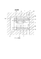
- a side rail 1 constitutes a combined oil ring (oil control ring) 3 together with a spacer expander 2.
- the combination oil ring 3 is a three-piece type in which a pair of side rails 1 are combined on both sides in the axial direction of the spacer expander 2, and as shown in FIG. It is used by being attached to a ring groove 4a formed on the outer peripheral surface of the piston 4 of the engine.
- the combination oil ring 3 may be a two-piece type in which only the side rail 1 is combined with the spacer expander 2.
- the spacer expander 2 is formed of a steel material in an annular shape that can be elastically deformed in the radially inward and outward directions, and is elastically deformed in the diameter reducing direction and mounted on the ring groove 4a of the piston 4 to radially Energize outward and axially outward.
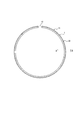
- the pair of side rails 1 have the same configuration as each other, and as shown in FIG. 3, the joint 10 is formed by bending a long and flat steel material (steel material). It is formed in the provided split ring shape. That is, the side rail 1 is formed in a C-shape in which a part in the circumferential direction is cut and the cut portion becomes the joint 10.
- the side rail 1 can be elastically deformed so as to expand the interval of the joint 10 in the circumferential direction, and the diameter can be expanded radially outward.
- the side rail 1 has a first axial side 11 facing one side in the axial direction (lower side in the drawing) and a second axis facing the other side (upper side in the drawing) in the axial direction.
- a direction side surface 12, an inner circumferential surface 13 facing inward in the radial direction, and an outer circumferential surface 14 facing outward in the radial direction are provided, and a cross-sectional shape perpendicular to the circumferential direction is substantially uniform over the entire circumference.
- the “axial direction” is a direction along the axial center of the split ring-shaped side rail 1.
- the first axial side surface 11 is formed in a flat surface perpendicular to the axial direction. As shown in FIG. 2, the first axial side surface 11 is directed to the crank chamber side of the engine in a state where the combined oil ring 3 using the side rail 1 is mounted on the piston 4.
- the second axial side 12 is formed in a flat surface that is perpendicular to the axial direction, that is, parallel to the first axial side 11. As shown in FIG. 2, the second axial side surface 12 is directed to the combustion chamber side of the engine in a state where the combined oil ring 3 using the side rail 1 is mounted on the piston 4.
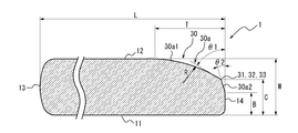
- the axial distance between the pair of axial side surfaces 11 and 12 of the side rail 1, that is, the axial thickness (rail width) W of the side rail 1 is 0.35 mm, and the inner peripheral surface 13 and the outer peripheral surface 14
- the distance L between them, ie, the radial length L, is 1.52 mm.
- the inner circumferential surface 13 of the side rail 1 is formed in a curved surface shape (barrel face) having an apex at the axial center position. As shown in FIG. 2, the inner circumferential surface 13 of the side rail 1 abuts on the seat surface 2 a of the spacer expander 2 in a state where the combined oil ring 3 using the side rail 1 is mounted on the piston 4.
- the inner peripheral surface 13 is not limited to the above-mentioned shape, and can adopt various shapes such as a cylindrical surface shape parallel to the axial direction, for example.
- the outer peripheral surface 14 of the side rail 1 is formed in a cylindrical surface shape parallel to the axial direction. As shown in FIG. 2, the side rail 1 contacts the cylinder inner surface 20 at the outer peripheral surface 14.
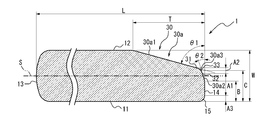
- a chamfered portion 30 is provided at one of the two axial end portions of the outer peripheral surface 14. That is, the chamfered portion 30 is provided between the outer peripheral surface 14 and the second axial side surface 12.
- the outer circumferential surface 14 and the first axial side surface 11 may be formed in a shape not provided with a chamfered portion, but may be formed in a rounded R shape, in which case the R shape Are formed smaller in radial width and axial width than the chamfered portion 30.
- the chamfered portion 30 is located on the outer peripheral surface 14 at which the first axial distance B from the first axial side surface 11 to the second axial side surface 12 is 0.05 mm or more, that is, the first axial direction. Starting from the position on the outer peripheral surface 14 axially separated by 0.05 mm or more from the side surface 11 to the second axial side surface 12, the position gradually shrinks from the starting point toward the second axial side surface 12. It is formed by a tapered surface 30 a that extends to the second axial side 12 while being diameter.
- the first axial distance B which is the starting point of the chamfered portion 30 is more preferably set to 0.10 mm or more.
- the tapered surface 30 a constituting the chamfered portion 30 is between the first tapered surface portion 30 a 1 which is inclined at an angle ⁇ 1 with respect to the axial direction, the first tapered surface portion 30 a 1 and the outer peripheral surface 14.
- a second tapered surface portion 30a2 is provided and inclined with respect to the axial direction at an angle ⁇ 2 smaller than the first tapered surface portion 30a1.
- the first tapered surface portion 30a1 is continuous with the second axial side surface 12 at the end on which the second axial side surface 12 is located.
- the second tapered surface portion 30a2 is continuous with the outer peripheral surface 14 at the end on which the first axial side surface 11 is located.
- An angle ⁇ 1 formed by the first tapered surface portion 30a1 with respect to the axial direction is 10 ° or more.
- the angle ⁇ 1 is preferably 30 ° or more.
- the difference between the angle ⁇ 1 formed by the first tapered surface portion 30a1 with the axial direction and the angle ⁇ 2 formed by the second tapered surface portion 30a2 with the axial direction is preferably 2 ° or more.
- the difference between the angle ⁇ 1 and the angle ⁇ 2 By setting the difference between the angle ⁇ 1 and the angle ⁇ 2 to 2 ° or more, the difference between the reflection angle of light reflected by the first tapered surface portion 30a1 and the reflection angle of light reflected by the second tapered surface portion 30a2 Of the chamfered portion 30 can be further enhanced.
- the chamfered portion 30 may collide with the cylinder inner surface 20 by tilting during the vertical movement of the piston 4. .
- the angle ⁇ 2 formed by the second tapered surface portion 30a2 with respect to the axial direction be smaller than the angle ⁇ 1 formed by the first tapered surface portion 30a1 with respect to the axial direction.
- the angle ⁇ 2 formed by the second tapered surface portion 30a2 with respect to the axial direction is preferably 2 ° or more and 10 ° or less.
- the axial distance of the second tapered surface portion 30a2 is preferably 0.10 mm or more, and is preferably 0.15 mm or more. More preferable.
- each of the first tapered surface portion 30a1 and the second tapered surface portion 30a2 is formed in a shape (conical surface shape) in which the diameter is linearly reduced, that is, a linear tapered surface.
- the radial length T of the chamfered portion 30, that is, the tapered surface 30a is preferably 0.05 mm or more.
- the chamfered portion 30 having visibility is provided at one of the two axial end portions of the outer peripheral surface 14 in the axial direction. Even when the side rail has vertical (upper and lower) directionality, visual inspection of the chamfered portion 30 by a worker, for example, at the time of manufacturing the side rail 1 or assembling work to the ring groove of the piston The upper and lower sides of the side rail 1 can be easily determined by the noncontact determination device of the formula or the like. Therefore, it is possible to prevent the side rail 1 from being assembled incorrectly in the wrong posture at the time of the work.
- the tapered surface 30a constituting the chamfered portion 30 has a first tapered surface portion 30a1 and a second tapered surface portion 30a2 inclined relative to the axial direction at an angle ⁇ 2 smaller than the first tapered surface portion 30a1.
- the angle ⁇ 2 formed by the second tapered surface portion 30a2 with the axial direction is preferably 2 ° or more and 12 ° or less, and more preferably 4 ° or more and 8 ° or less preferable.
- the end 31 of the first tapered surface 30a1 on the side where the first axial side 11 is located and the second axial side 12 of the second tapered surface 30a2 are located.
- the second axial distance C along the axial direction from the axial center position 33 of the side end 32 to the first axial side 11 is 60% of the axial thickness W of the side rail 1
- the size is preferably 80% or less.
- the region of the second tapered surface portion 30a2 can be secured at a certain level or more, so oil consumption is reduced. It can be done.
- the axial center position 33 is the same position as the end portions 31 and 32.
- the tapered surface 30a constituting the chamfered portion 30 is provided with a curved tapered surface subportion 30a3 between the first tapered surface portion 30a1 and the second tapered surface portion 30a2, and this tapered surface subportion
- the first tapered surface portion 30a1 and the second tapered surface portion 30a2 can be smoothly connected by the portion 30a3.
- the tapered surface subportion 30a3 is preferably in the form of a curved surface having a constant radius of curvature, but may be in the form of a curved surface in which the radius of curvature gradually changes.
- each of the first tapered surface portion 30a1 and the second tapered surface portion 30a2 similarly to the example shown in FIG. 4, each of the first tapered surface portion 30a1 and the second tapered surface portion 30a2 has a shape (conical surface shape) that linearly reduces in diameter. It is formed in a linear taper surface.
- the outer peripheral surface is formed by providing the curved surface sub-portion 30a3 between the first taper surface portion 30a1 and the second taper surface portion 30a2 as the taper surface 30a constituting the chamfered portion 30.
- the oil scraping by the edge of the surface 14 can be more effectively prevented to further reduce the oil consumption.
- the angle ⁇ 1 formed by the first tapered surface portion 30a1 with respect to the axial direction is 10 ° or more and 30 ° or more. preferable.
- the difference between the angle ⁇ 1 formed by the first tapered surface portion 30a1 with the axial direction and the angle ⁇ 2 formed by the second tapered surface portion 30a2 with the axial direction is preferably 2 ° or more.
- the angle ⁇ 2 formed by the second tapered surface portion 30a2 with respect to the axial direction is preferably 2 ° or more and 12 ° or less.
- the second axial distance C along the axial direction from the axial center position 33 to the first axial side 11 is 60% to 80% of the axial thickness W of the side rail 1 Is preferred.
- the axial center position 33 is located at the axial center of the tapered surface subportion 30a3.
- the first tapered surface portion 30a1 of the chamfered portion 30 can also be formed in a curved shape.
- the first tapered surface portion 30a1 is preferably in the form of a curved surface having a constant radius of curvature, but may be in the form of a curved surface in which the radius of curvature gradually changes.
- the second tapered surface portion 30a2 is formed in a shape (conical surface shape) that linearly reduces in diameter, that is, a linear tapered surface.
- the chamfered portion 30 can be more easily visually recognized, and the upper and lower side discrimination of the side rail 1 can be further facilitated. it can.
- the angle ⁇ 1 formed by the first tapered surface portion 30a1 with respect to the axial direction is 10 ° or more, and 30 ° or more. Is preferred.
- the difference between the angle ⁇ 1 formed by the first tapered surface portion 30a1 with the axial direction and the angle ⁇ 2 formed by the second tapered surface portion 30a2 with the axial direction is preferably 2 ° or more.
- the angle ⁇ 2 formed by the second tapered surface portion 30a2 with respect to the axial direction is preferably 2 ° or more and 12 ° or less.
- the second axial distance C along the axial direction from the axial center position 33 to the first axial side 11 is 60% to 80% of the axial thickness W of the side rail 1 Is preferred.
- the angle ⁇ 1 formed by the curved first taper surface portion 30a1 with respect to the axial direction is the end of the first taper surface portion 30a1 on the side where the first axial side surface 11 is located. It is assumed that the tangent of the first tapered surface portion 30a1 in the portion 31 is at an angle with respect to the axial direction.
- taper surface subportion 30a3 is not provided between the first taper surface portion 30a1 and the second taper surface portion 30a2, the first taper surface portion 30a1 and the second taper surface portion are provided.
- a tapered surface sub-portion 30a3 may be provided between it and 30a2.
- the area of the chamfered portion 30 which combines the second tapered surface portion 30a2 facing outward in the radial direction and the outer peripheral surface 14 is the outer peripheral surface area A1, the upper and lower sides of the side rail 1 can be easily discriminated.
- the area A3 of the lower end surface 15 is asymmetrical with respect to a virtual surface S passing through an axial intermediate position between the first axial side 11 and the second axial side 12.
- the outer peripheral surface area A1 of the side rail 1 is preferably formed in an asymmetrical shape in the axial direction.
- the asymmetric shape may be as follows. That is, a line perpendicular to the axial direction through the axial center is defined as the first intermediate line, and at the outer peripheral tip where the contour curve of the outer peripheral surface in the vertical cross section is traced, from the outer peripheral vertex to the inner peripheral side in the radial direction
- the position on the combustion chamber side of the engine among the two positions on the contour curve at the 3 ⁇ m facing distance is a position a1
- the position on the side away from the combustion chamber of the engine is a position b1, and between these positions a1 and b1.
- the second middle line is located farther from the engine combustion chamber than the first middle line .
- the outer circumferential apex of the side rail 1 is located on the second intermediate line or on the side farther from the engine combustion chamber than the second intermediate line.
- the contour curve of the outer peripheral surface in the vertical cross section is directed from the outer peripheral vertex of the side rail 1 toward the inner peripheral side in the radial direction so that a symmetrical shape having the axial both end sides as a pair exists at the inner peripheral side position in the radial direction. Is traced to at least 0.025 mm.
- the asymmetrical contour curve at the outer peripheral tip of the side rail 1 is directed toward the inner peripheral side in the radial direction from the outer peripheral apex and the outer peripheral apex at a distance of 1.5 ⁇ m and from the outer peripheral apex toward the inner peripheral side in the radial direction
- the first contour division is divided into the contour portion sandwiched by the distance 1.5 ⁇ m and the distance 3.0 ⁇ m, and the first contour division, the second contour division, and the third contour division from the combustion chamber side of the engine of the cylinder Starting from a first end of the second contour section on the combustion chamber side of the engine, it is provided in part of a linear shape or a quadratic curve shape.
- the second contour segment has an outer circumferential vertex in the middle thereof and is provided in an arc shape.
- the third contour section is provided so as to be a part of a quadratic curve shape, with the second end away from the combustion chamber of the engine of the second contour section as a starting point.
- the surface roughness of the asymmetric portion of the outer peripheral surface of the side rail 1 is 0.6 ⁇ mRp or less.
- the asymmetric shape of the outer peripheral surface area A1 of the side rail 1 may be as follows. That is, a line passing through the center of the segment width is taken as the first middle line, and at the outer peripheral tip end where the contour curve of the outer peripheral surface in the longitudinal section is traced, at a position 3 ⁇ m away from the outer peripheral vertex toward the inner peripheral side Of the two positions on the contour curve, the position on the combustion chamber side of the engine is the position a1, the position on the side away from the combustion chamber of the engine is the position b1, and the length of the line segment between these positions a1 and b1 is The second intermediate line is positioned on the side farther from the engine combustion chamber than the first intermediate line, where L1 is the intermediate line of the line segment of the length L1 as the second intermediate line.
- the outer circumferential apex of the side rail 1 is located on the second intermediate line or on the side farther from the engine combustion chamber than the second intermediate line. Further, the contour curve of the outer peripheral surface in the vertical cross section is directed from the outer peripheral vertex of the side rail 1 toward the inner peripheral side in the radial direction so that a symmetrical shape having the axial both end sides as a pair exists at the inner peripheral side position in the radial direction. Is traced to at least 0.025 mm.
- the asymmetrical contour curve at the outer peripheral tip of the side rail 1 is directed toward the inner peripheral side in the radial direction toward the inner peripheral side of the segment radial direction with the curved portion sandwiched between the outer peripheral vertex and the outer peripheral vertex at a distance of 1.5 ⁇ m
- the first contour division Is provided in a portion of a linear shape or a quadratic curve shape starting from a first end on the combustion chamber side of the engine of the second contour section.
- the second contour section has a flat portion in the middle, and is a part of a linear shape or a quadratic curve shape from the end on the combustion chamber side of the engine in the axial direction of the flat portion and is continuous to the first contour section
- the flat portion is provided in a shape continuous with the third contour section from the end portion of the flat portion in the axial direction away from the combustion chamber of the engine.
- the third contour section is provided to be part of a quadratic curve shape continuous to the second end.
- the surface roughness of the asymmetric portion of the outer peripheral surface of the side rail 1 is 0.6 ⁇ mRp or less.
- a line in the radial direction orthogonal to the line segment between the position a1 and the position b1 and divided by a line passing through the outer peripheral vertex The length on the position a1 side is L2, the length on the position b1 side is L3, and the position on the combustion chamber side of the engine at two positions on the contour curve at a distance of 1.5 ⁇ m toward the inner peripheral side in the radial direction a2, assuming that the position away from the combustion chamber of the engine is position b2, the length of the line segment between position a2 and position b2 is L4, and the axial length of the flat portion of the second contour section is L5 Assuming that the following conditions are satisfied: 0.05 mm ⁇ L1 ⁇ 0.15 mm, L2 / L1 / 0.5, L4 / L1 ⁇ 0.76, 0 ⁇ L5 ⁇ 0.05 mm.
- the area A2 of the tapered surface subportion 30a3 and the area A3 of the outer peripheral lower end surface are axially intermediate positions of the first axial side 11 and the second axial side 12
- a hard coating may be provided on at least the outer peripheral surface 14 and the chamfered portion 30, ie, the surface of the tapered surface 30a.
- the hard coating for example, a configuration provided with at least one of a nitrided layer, a PVD treated layer, a hard chromium plated layer, and a DLC layer can be adopted.
- PVD-treated layer means “layer formed by physical vapor deposition (Physical Vapor Deposition)", and “DLC (Diamond Like Carbon) layer” means a non-hydrocarbon or carbon allotrope mainly. Amorphous hard carbon film is meant.
- the hue of the chamfered portion 30 visually recognized can be changed more clearly with respect to the second axial side surface 12 and the outer peripheral surface 14 .
- the difference in hue becomes larger. Therefore, by providing the hard film, the chamfered portion 30 can be more easily visually recognized, and the upper and lower discrimination of the side rail 1 can be further facilitated.
- Example 1 4 with an axial thickness (W) of 0.35 mm, a first axial distance (B) indicating the chamfered position of the chamfered portion of 0.15 mm, and a first tapered surface portion of the chamfered portion Prepare 100 side rails with an angle ( ⁇ 1) to the axial direction of 30 ° and an angle ( ⁇ 2) to the axial direction of the second tapered surface part of 6 °, and visually check these side rails by 10 workers. The upper and lower direction discrimination in. As a result, the workers were able to correctly determine the upper and lower directionality of all side rails.
- Example 2 While having the shape shown in FIG. 4, the axial thickness (W) is 0.35 mm, the radial length (L) is 1.62 mm, and the first axial distance (B) indicating the chamfer position of the chamfer is 0 .15 mm, the second axial distance (C) is 67% of the axial thickness (W), that is, 0.23 mm, and the angle ( ⁇ 1) of the first tapered surface of the chamfer to the axial direction is 15 °
- Example 3 A plurality of combined oil rings each made up of the plurality of side rails used in Example 2 were produced.
- a plurality of pistons were prepared in which a plurality of combined oil rings manufactured were attached to each ring groove, and the amount of oil consumption was measured when reciprocating a predetermined number of times in a cylinder.
- the oil when operated for a specified period of time under conditions of 6000 rpm and full load (WOT: Wide Open Throttle) Consumption was measured.
- WOT Wide Open Throttle
- the oil consumption ratio is assumed to be 100 where the oil consumption when using the side rail formed in a curved surface shape (barrel face) having an apex at the axial center position in the outer peripheral surface is 100.
- the measured oil consumption As shown in FIG. 7, the oil consumption can be reduced if the angle ( ⁇ 2) of the second tapered surface with respect to the axial direction is 2 ° or more and 12 ° or less, and if 4 ° or more and 8 ° or less, the oil consumption It was found that the amount could be further reduced.
- angle ( ⁇ 2) of the second tapered surface with respect to the axial direction is 2 ° or more and 12 ° or less, it is not confirmed that the inner surface of the cylinder is scratched, so that the collision of the chamfer with the inner surface of the cylinder is alleviated. It is thought that
- the outer peripheral surface 14 is formed in a cylindrical surface shape parallel to the axial direction in the above embodiment, the outer peripheral surface 14 may be formed in other shapes such as upper and lower (front and back) asymmetric shapes having a slight shape change. it can.
Landscapes
- Engineering & Computer Science (AREA)
- General Engineering & Computer Science (AREA)
- Mechanical Engineering (AREA)
- Chemical & Material Sciences (AREA)
- Combustion & Propulsion (AREA)
- Pistons, Piston Rings, And Cylinders (AREA)
Priority Applications (5)
| Application Number | Priority Date | Filing Date | Title |
|---|---|---|---|
| KR1020227012712A KR20220053049A (ko) | 2017-10-05 | 2018-09-25 | 사이드 레일 |
| CN201880063554.2A CN111148893B (zh) | 2017-10-05 | 2018-09-25 | 侧轨 |
| US16/652,071 US11448317B2 (en) | 2017-10-05 | 2018-09-25 | Side rail |
| KR1020207009765A KR20200080229A (ko) | 2017-10-05 | 2018-09-25 | 사이드 레일 |
| EP18865205.1A EP3677764B1 (en) | 2017-10-05 | 2018-09-25 | Side rail |
Applications Claiming Priority (2)
| Application Number | Priority Date | Filing Date | Title |
|---|---|---|---|
| JP2017-195287 | 2017-10-05 | ||
| JP2017195287A JP6603284B2 (ja) | 2017-10-05 | 2017-10-05 | サイドレール |
Publications (1)
| Publication Number | Publication Date |
|---|---|
| WO2019069748A1 true WO2019069748A1 (ja) | 2019-04-11 |
Family
ID=65994675
Family Applications (1)
| Application Number | Title | Priority Date | Filing Date |
|---|---|---|---|
| PCT/JP2018/035483 Ceased WO2019069748A1 (ja) | 2017-10-05 | 2018-09-25 | サイドレール |
Country Status (6)
| Country | Link |
|---|---|
| US (1) | US11448317B2 (enExample) |
| EP (1) | EP3677764B1 (enExample) |
| JP (1) | JP6603284B2 (enExample) |
| KR (2) | KR20200080229A (enExample) |
| CN (1) | CN111148893B (enExample) |
| WO (1) | WO2019069748A1 (enExample) |
Cited By (2)
| Publication number | Priority date | Publication date | Assignee | Title |
|---|---|---|---|---|
| WO2023013265A1 (ja) * | 2021-08-05 | 2023-02-09 | Tpr株式会社 | オイルリング |
| US20250052320A1 (en) * | 2021-12-28 | 2025-02-13 | Kabushiki Kaisha Riken | Piston ring and piston ring set |
Families Citing this family (1)
| Publication number | Priority date | Publication date | Assignee | Title |
|---|---|---|---|---|
| US11994219B2 (en) * | 2021-03-31 | 2024-05-28 | Kabushiki Kaisha Riken | Side rail and oil control ring comprising same |
Citations (8)
| Publication number | Priority date | Publication date | Assignee | Title |
|---|---|---|---|---|
| JPS5763951U (enExample) * | 1980-10-03 | 1982-04-16 | ||
| JPS5833276B2 (ja) | 1978-09-13 | 1983-07-19 | コンポザン・アンダストリアリゼ・デユ・バテイモン・パ−ル・アブレヴイアシオン・セ−・イ−・ベ− | ポリマ−含有ビチユ−メン組成物 |
| JPH051062U (ja) * | 1991-06-21 | 1993-01-08 | 日野自動車工業株式会社 | ピストンリングの嵌合部構造 |
| JP2003049705A (ja) * | 2001-08-03 | 2003-02-21 | Nippon Piston Ring Co Ltd | 内燃機関の1本リング構成ピストン |
| JP2003194222A (ja) | 2001-12-28 | 2003-07-09 | Riken Corp | サイドレール及び組合せオイルリング |
| JP2016035326A (ja) * | 2014-07-31 | 2016-03-17 | 日本ピストンリング株式会社 | 組合せオイルリング |
| JP2016156411A (ja) * | 2015-02-23 | 2016-09-01 | 株式会社リケン | サイドレール |
| JP2016169791A (ja) * | 2015-03-12 | 2016-09-23 | 株式会社リケン | サイドレール |
Family Cites Families (23)
| Publication number | Priority date | Publication date | Assignee | Title |
|---|---|---|---|---|
| US2905512A (en) * | 1958-04-24 | 1959-09-22 | Ramsey Corp | Coated piston ring |
| US4497497A (en) * | 1984-06-21 | 1985-02-05 | Allis-Chalmers Corp. | Oil ring assembly with annular expander spring |
| JPH04117956U (ja) * | 1991-04-04 | 1992-10-22 | 帝国ピストンリング株式会社 | 組合せオイルリング |
| JP2003113940A (ja) * | 2001-08-02 | 2003-04-18 | Riken Corp | スチール製ピストンリング |
| US7354045B2 (en) * | 2002-10-29 | 2008-04-08 | Toyota Jidosha Kabushiki Kaisha | Oil ring |
| CN100410569C (zh) * | 2002-10-29 | 2008-08-13 | 丰田自动车株式会社 | 油环 |
| JP4322500B2 (ja) * | 2002-12-18 | 2009-09-02 | 帝国ピストンリング株式会社 | 組合せオイルリング |
| EP2508740B1 (en) * | 2009-11-30 | 2017-05-31 | Nippon Piston Ring Co., Ltd. | Piston ring |
| WO2011132679A1 (ja) * | 2010-04-19 | 2011-10-27 | 日本ピストンリング株式会社 | 内燃機関用オイルリング |
| WO2011151927A1 (ja) * | 2010-06-04 | 2011-12-08 | 日本ピストンリング株式会社 | 内燃機関用オイルリング |
| US8640314B2 (en) * | 2010-08-03 | 2014-02-04 | Federal-Mogul Corporation | Piston assembly transportation and installation apparatus and methods of transporting and installing a piston assembly therewith |
| DE102011120145A1 (de) * | 2010-12-24 | 2012-06-28 | Mahle International Gmbh | Kolbenring für einen Kolben eines Verbrennungsmotors und Verfahren zu seiner Herstellung |
| CN103403409B (zh) * | 2011-02-28 | 2016-10-26 | 日本活塞环株式会社 | 活塞环 |
| JP5564082B2 (ja) * | 2012-08-09 | 2014-07-30 | 株式会社リケン | テーパフェイス形圧力リング用線材及びテーパフェイス形圧力リング |
| CN203962189U (zh) * | 2013-11-19 | 2014-11-26 | 浙江吉利汽车研究院有限公司 | 一种汽车发动机活塞的油环 |
| US10253882B2 (en) * | 2013-12-30 | 2019-04-09 | Mahle International Gmbh | Oil control ring assembly |
| US20160040780A1 (en) * | 2014-08-05 | 2016-02-11 | General Electric Company | Piston assembly for a reciprocating engine |
| US20160040622A1 (en) * | 2014-08-05 | 2016-02-11 | General Electric Company | Piston assembly for a reciprocating engine |
| MX356143B (es) * | 2014-09-12 | 2018-05-16 | Tpr Co Ltd | Anillo de aceite de combinación. |
| JP5833276B1 (ja) * | 2014-09-12 | 2015-12-16 | Tpr株式会社 | 組合せオイルリング |
| CN204082367U (zh) * | 2014-09-24 | 2015-01-07 | 仪征威龙发动机零部件有限公司 | 一种低油耗活塞环油环 |
| JP6762657B2 (ja) * | 2016-04-06 | 2020-09-30 | 株式会社リケン | サイドレール |
| CN109416124B (zh) * | 2017-07-05 | 2020-04-14 | 帝伯爱尔株式会社 | 组合油环 |
-
2017
- 2017-10-05 JP JP2017195287A patent/JP6603284B2/ja active Active
-
2018
- 2018-09-25 WO PCT/JP2018/035483 patent/WO2019069748A1/ja not_active Ceased
- 2018-09-25 KR KR1020207009765A patent/KR20200080229A/ko not_active Ceased
- 2018-09-25 EP EP18865205.1A patent/EP3677764B1/en active Active
- 2018-09-25 US US16/652,071 patent/US11448317B2/en active Active
- 2018-09-25 CN CN201880063554.2A patent/CN111148893B/zh active Active
- 2018-09-25 KR KR1020227012712A patent/KR20220053049A/ko not_active Ceased
Patent Citations (8)
| Publication number | Priority date | Publication date | Assignee | Title |
|---|---|---|---|---|
| JPS5833276B2 (ja) | 1978-09-13 | 1983-07-19 | コンポザン・アンダストリアリゼ・デユ・バテイモン・パ−ル・アブレヴイアシオン・セ−・イ−・ベ− | ポリマ−含有ビチユ−メン組成物 |
| JPS5763951U (enExample) * | 1980-10-03 | 1982-04-16 | ||
| JPH051062U (ja) * | 1991-06-21 | 1993-01-08 | 日野自動車工業株式会社 | ピストンリングの嵌合部構造 |
| JP2003049705A (ja) * | 2001-08-03 | 2003-02-21 | Nippon Piston Ring Co Ltd | 内燃機関の1本リング構成ピストン |
| JP2003194222A (ja) | 2001-12-28 | 2003-07-09 | Riken Corp | サイドレール及び組合せオイルリング |
| JP2016035326A (ja) * | 2014-07-31 | 2016-03-17 | 日本ピストンリング株式会社 | 組合せオイルリング |
| JP2016156411A (ja) * | 2015-02-23 | 2016-09-01 | 株式会社リケン | サイドレール |
| JP2016169791A (ja) * | 2015-03-12 | 2016-09-23 | 株式会社リケン | サイドレール |
Non-Patent Citations (1)
| Title |
|---|
| See also references of EP3677764A4 |
Cited By (4)
| Publication number | Priority date | Publication date | Assignee | Title |
|---|---|---|---|---|
| WO2023013265A1 (ja) * | 2021-08-05 | 2023-02-09 | Tpr株式会社 | オイルリング |
| JP7224404B1 (ja) | 2021-08-05 | 2023-02-17 | Tpr株式会社 | オイルリング |
| JP2023026722A (ja) * | 2021-08-05 | 2023-02-28 | Tpr株式会社 | オイルリング |
| US20250052320A1 (en) * | 2021-12-28 | 2025-02-13 | Kabushiki Kaisha Riken | Piston ring and piston ring set |
Also Published As
| Publication number | Publication date |
|---|---|
| KR20220053049A (ko) | 2022-04-28 |
| CN111148893B (zh) | 2022-08-30 |
| US11448317B2 (en) | 2022-09-20 |
| JP2019065830A (ja) | 2019-04-25 |
| CN111148893A (zh) | 2020-05-12 |
| EP3677764A4 (en) | 2020-10-28 |
| US20200248808A1 (en) | 2020-08-06 |
| JP6603284B2 (ja) | 2019-11-06 |
| KR20200080229A (ko) | 2020-07-06 |
| EP3677764B1 (en) | 2022-11-02 |
| EP3677764A1 (en) | 2020-07-08 |
Similar Documents
| Publication | Publication Date | Title |
|---|---|---|
| JP6530200B2 (ja) | サイドレール | |
| JP6533670B2 (ja) | サイドレール | |
| US10352445B2 (en) | Piston ring | |
| JP7254836B2 (ja) | 組合せオイルリング | |
| US20170227126A1 (en) | Combined oil ring | |
| WO2019069748A1 (ja) | サイドレール | |
| EP3043054A1 (en) | Cuff-ring for a cylinder liner | |
| JP6695663B2 (ja) | 内燃機関用のピストンリング | |
| JP6762657B2 (ja) | サイドレール | |
| WO2016092776A1 (ja) | オイルリング | |
| JP6467222B2 (ja) | 組合せオイルリング | |
| JP7307778B2 (ja) | ピストンリングの組合せ、及び内燃機関 | |
| JP6659892B2 (ja) | サイドレール | |
| WO2018198173A1 (ja) | サイドレール | |
| JP6491286B2 (ja) | オイルリング | |
| JP6438679B2 (ja) | オイルリング | |
| WO2019142668A1 (ja) | オイルリング |
Legal Events
| Date | Code | Title | Description |
|---|---|---|---|
| 121 | Ep: the epo has been informed by wipo that ep was designated in this application |
Ref document number: 18865205 Country of ref document: EP Kind code of ref document: A1 |
|
| NENP | Non-entry into the national phase |
Ref country code: DE |
|
| ENP | Entry into the national phase |
Ref document number: 2018865205 Country of ref document: EP Effective date: 20200402 |