WO2019069748A1 - Side rail - Google Patents
Side rail Download PDFInfo
- Publication number
- WO2019069748A1 WO2019069748A1 PCT/JP2018/035483 JP2018035483W WO2019069748A1 WO 2019069748 A1 WO2019069748 A1 WO 2019069748A1 JP 2018035483 W JP2018035483 W JP 2018035483W WO 2019069748 A1 WO2019069748 A1 WO 2019069748A1
- Authority
- WO
- WIPO (PCT)
- Prior art keywords
- axial
- tapered surface
- outer peripheral
- axial direction
- side rail
- Prior art date
Links
Images


Classifications
-
- F—MECHANICAL ENGINEERING; LIGHTING; HEATING; WEAPONS; BLASTING
- F16—ENGINEERING ELEMENTS AND UNITS; GENERAL MEASURES FOR PRODUCING AND MAINTAINING EFFECTIVE FUNCTIONING OF MACHINES OR INSTALLATIONS; THERMAL INSULATION IN GENERAL
- F16J—PISTONS; CYLINDERS; SEALINGS
- F16J9/00—Piston-rings, e.g. non-metallic piston-rings, seats therefor; Ring sealings of similar construction
- F16J9/06—Piston-rings, e.g. non-metallic piston-rings, seats therefor; Ring sealings of similar construction using separate springs or elastic elements expanding the rings; Springs therefor ; Expansion by wedging
- F16J9/064—Rings with a flat annular side rail
- F16J9/066—Spring expander from sheet metal
- F16J9/068—Spring expander from sheet metal corrugated in the axial direction
-
- F—MECHANICAL ENGINEERING; LIGHTING; HEATING; WEAPONS; BLASTING
- F02—COMBUSTION ENGINES; HOT-GAS OR COMBUSTION-PRODUCT ENGINE PLANTS
- F02F—CYLINDERS, PISTONS OR CASINGS, FOR COMBUSTION ENGINES; ARRANGEMENTS OF SEALINGS IN COMBUSTION ENGINES
- F02F5/00—Piston rings, e.g. associated with piston crown
-
- F—MECHANICAL ENGINEERING; LIGHTING; HEATING; WEAPONS; BLASTING
- F16—ENGINEERING ELEMENTS AND UNITS; GENERAL MEASURES FOR PRODUCING AND MAINTAINING EFFECTIVE FUNCTIONING OF MACHINES OR INSTALLATIONS; THERMAL INSULATION IN GENERAL
- F16J—PISTONS; CYLINDERS; SEALINGS
- F16J9/00—Piston-rings, e.g. non-metallic piston-rings, seats therefor; Ring sealings of similar construction
- F16J9/12—Details
- F16J9/20—Rings with special cross-section; Oil-scraping rings
Definitions
- the present invention relates to a side rail which is combined with a toroidal spacer expander to constitute a combined oil ring for an internal combustion engine together with the spacer expander.
- an oil ring for controlling the oil on the inner surface of the cylinder is attached to the piston of the reciprocating engine (reciprocating internal combustion engine).
- a combined oil ring configured by combining an annular spacer expander and one or a pair of side rails is often used.
- the side rail used in the combination oil ring is formed in a split ring shape having an abutment, and is urged to expand the diameter by a spacer expander, and a predetermined contact pressure (surface pressure) against the inner surface of the cylinder on its outer peripheral surface Contact with Then, when the engine operates and the piston reciprocates, the side rail slides on the inner surface of the cylinder on its outer peripheral surface to form an oil film of an appropriate thickness on the inner surface of the cylinder and excess oil adhering to the inner surface of the cylinder. Scrape toward the crankcase to prevent oil from rising.
- Patent Document 1 describes a side rail in which an outer peripheral surface facing radially outward is formed in a curved surface shape having an apex at an axial center position and protruding outward in the radial direction.
- Patent Document 2 a pair of an outer peripheral surface including an outer peripheral vertex portion and an asymmetric region which is asymmetric with respect to the axial direction, and a pair of axial regions symmetrical with each other in the axial direction across the asymmetric region.
- a side rail is described which is configured to have a symmetrical area.
- An object of the present invention is to solve such a point, and it is an object of the present invention to provide a side rail which makes it easy to determine the vertical direction.
- the side rail of the present invention is formed in a split ring shape having a joint, and is a side rail combined with an annular spacer expander to constitute a combined oil ring for an internal combustion engine together with the spacer expander.
- the outer peripheral surface has a chamfered portion between the outer peripheral surface and the second axial side, and the chamfered portion extends from the first axial side to the second shaft
- the tapered surface is formed by a tapered surface whose diameter gradually decreases toward the second axial side from the position on the outer circumferential surface which is axially separated by 0.05 mm or more in the axial direction toward the directional side.
- a second tapered surface provided between a first tapered surface portion having an angle of 10 ° or more and the first tapered surface portion and the outer peripheral surface and having a smaller inclination angle with respect to the axial direction than the first tapered surface portion. And a face portion.
- the “split ring shape provided with a joint portion” is formed in a C shape in which the oil ring main body is cut in a part in the circumferential direction and the cut portion becomes a joint portion. It means that.
- an axial direction means the direction in alignment with the axial center of the side rail of a split ring shape.
- the difference between the angle formed by the first tapered surface portion with respect to the axial direction and the angle formed by the second tapered surface portion with respect to the axial direction is 2 ° or more preferable.
- an angle formed by the second tapered surface portion with respect to the axial direction is 2 ° or more and 12 ° or less.
- the present invention is the end on the side where the first axial side of the first tapered surface is located, and the end on which the second axial side of the second tapered surface is located.
- the distance along the axial direction from the axial center position of the end portion to the first axial side surface is 60% to 80% of the axial thickness of the side rail preferable.
- the first taper surface portion and the second taper surface portion are smoothly connected by a curved surface subportion.
- the tapered surface is provided so as to sandwich the outer peripheral surface region in the axial direction when the region obtained by combining the outer peripheral surface and the second tapered surface portion is the outer peripheral surface region.
- the region of the sub-portion and the region of the outer peripheral lower end surface of the curved surface shape provided between the outer peripheral surface and the first axial side are the first axial side and the second axial side. Preferably, they are asymmetrical with respect to a virtual plane passing through an axial intermediate position.
- the first tapered surface portion is formed in a curved shape.
- a hard film is provided on the outer peripheral surface and the surface of the chamfered portion.
- the chamfered portion having visibility is provided between the outer peripheral surface and the second axial side surface, even when the side rail has upper and lower (front and back) directivity, at the time of manufacturing
- the upper and lower sides of the side rail can be easily determined by visually observing the chamfered portion at the time of assembling the piston into the ring groove or the like.
- FIG. 4 is a cross-sectional view taken along the line AA in FIG. 3; It is a modification of the side rail shown in FIG. 4, Comprising: It is sectional drawing at the time of providing a taper surface subpart between a 1st taper surface part and a 2nd taper surface part. It is a modification of the side rail shown in FIG. 4, Comprising: It is sectional drawing at the time of forming a 1st taper surface part in curved surface shape. It is a graph which shows the relationship between the angle with respect to the axial direction of the 2nd taper surface part in Example 3, and oil consumption ratio.
- a side rail 1 constitutes a combined oil ring (oil control ring) 3 together with a spacer expander 2.
- the combination oil ring 3 is a three-piece type in which a pair of side rails 1 are combined on both sides in the axial direction of the spacer expander 2, and as shown in FIG. It is used by being attached to a ring groove 4a formed on the outer peripheral surface of the piston 4 of the engine.
- the combination oil ring 3 may be a two-piece type in which only the side rail 1 is combined with the spacer expander 2.
- the spacer expander 2 is formed of a steel material in an annular shape that can be elastically deformed in the radially inward and outward directions, and is elastically deformed in the diameter reducing direction and mounted on the ring groove 4a of the piston 4 to radially Energize outward and axially outward.
- the pair of side rails 1 have the same configuration as each other, and as shown in FIG. 3, the joint 10 is formed by bending a long and flat steel material (steel material). It is formed in the provided split ring shape. That is, the side rail 1 is formed in a C-shape in which a part in the circumferential direction is cut and the cut portion becomes the joint 10.
- the side rail 1 can be elastically deformed so as to expand the interval of the joint 10 in the circumferential direction, and the diameter can be expanded radially outward.
- the side rail 1 has a first axial side 11 facing one side in the axial direction (lower side in the drawing) and a second axis facing the other side (upper side in the drawing) in the axial direction.
- a direction side surface 12, an inner circumferential surface 13 facing inward in the radial direction, and an outer circumferential surface 14 facing outward in the radial direction are provided, and a cross-sectional shape perpendicular to the circumferential direction is substantially uniform over the entire circumference.
- the “axial direction” is a direction along the axial center of the split ring-shaped side rail 1.
- the first axial side surface 11 is formed in a flat surface perpendicular to the axial direction. As shown in FIG. 2, the first axial side surface 11 is directed to the crank chamber side of the engine in a state where the combined oil ring 3 using the side rail 1 is mounted on the piston 4.
- the second axial side 12 is formed in a flat surface that is perpendicular to the axial direction, that is, parallel to the first axial side 11. As shown in FIG. 2, the second axial side surface 12 is directed to the combustion chamber side of the engine in a state where the combined oil ring 3 using the side rail 1 is mounted on the piston 4.
- the axial distance between the pair of axial side surfaces 11 and 12 of the side rail 1, that is, the axial thickness (rail width) W of the side rail 1 is 0.35 mm, and the inner peripheral surface 13 and the outer peripheral surface 14
- the distance L between them, ie, the radial length L, is 1.52 mm.
- the inner circumferential surface 13 of the side rail 1 is formed in a curved surface shape (barrel face) having an apex at the axial center position. As shown in FIG. 2, the inner circumferential surface 13 of the side rail 1 abuts on the seat surface 2 a of the spacer expander 2 in a state where the combined oil ring 3 using the side rail 1 is mounted on the piston 4.
- the inner peripheral surface 13 is not limited to the above-mentioned shape, and can adopt various shapes such as a cylindrical surface shape parallel to the axial direction, for example.
- the outer peripheral surface 14 of the side rail 1 is formed in a cylindrical surface shape parallel to the axial direction. As shown in FIG. 2, the side rail 1 contacts the cylinder inner surface 20 at the outer peripheral surface 14.
- a chamfered portion 30 is provided at one of the two axial end portions of the outer peripheral surface 14. That is, the chamfered portion 30 is provided between the outer peripheral surface 14 and the second axial side surface 12.
- the outer circumferential surface 14 and the first axial side surface 11 may be formed in a shape not provided with a chamfered portion, but may be formed in a rounded R shape, in which case the R shape Are formed smaller in radial width and axial width than the chamfered portion 30.
- the chamfered portion 30 is located on the outer peripheral surface 14 at which the first axial distance B from the first axial side surface 11 to the second axial side surface 12 is 0.05 mm or more, that is, the first axial direction. Starting from the position on the outer peripheral surface 14 axially separated by 0.05 mm or more from the side surface 11 to the second axial side surface 12, the position gradually shrinks from the starting point toward the second axial side surface 12. It is formed by a tapered surface 30 a that extends to the second axial side 12 while being diameter.
- the first axial distance B which is the starting point of the chamfered portion 30 is more preferably set to 0.10 mm or more.
- the tapered surface 30 a constituting the chamfered portion 30 is between the first tapered surface portion 30 a 1 which is inclined at an angle ⁇ 1 with respect to the axial direction, the first tapered surface portion 30 a 1 and the outer peripheral surface 14.
- a second tapered surface portion 30a2 is provided and inclined with respect to the axial direction at an angle ⁇ 2 smaller than the first tapered surface portion 30a1.
- the first tapered surface portion 30a1 is continuous with the second axial side surface 12 at the end on which the second axial side surface 12 is located.
- the second tapered surface portion 30a2 is continuous with the outer peripheral surface 14 at the end on which the first axial side surface 11 is located.
- An angle ⁇ 1 formed by the first tapered surface portion 30a1 with respect to the axial direction is 10 ° or more.
- the angle ⁇ 1 is preferably 30 ° or more.
- the difference between the angle ⁇ 1 formed by the first tapered surface portion 30a1 with the axial direction and the angle ⁇ 2 formed by the second tapered surface portion 30a2 with the axial direction is preferably 2 ° or more.
- the difference between the angle ⁇ 1 and the angle ⁇ 2 By setting the difference between the angle ⁇ 1 and the angle ⁇ 2 to 2 ° or more, the difference between the reflection angle of light reflected by the first tapered surface portion 30a1 and the reflection angle of light reflected by the second tapered surface portion 30a2 Of the chamfered portion 30 can be further enhanced.
- the chamfered portion 30 may collide with the cylinder inner surface 20 by tilting during the vertical movement of the piston 4. .
- the angle ⁇ 2 formed by the second tapered surface portion 30a2 with respect to the axial direction be smaller than the angle ⁇ 1 formed by the first tapered surface portion 30a1 with respect to the axial direction.
- the angle ⁇ 2 formed by the second tapered surface portion 30a2 with respect to the axial direction is preferably 2 ° or more and 10 ° or less.
- the axial distance of the second tapered surface portion 30a2 is preferably 0.10 mm or more, and is preferably 0.15 mm or more. More preferable.
- each of the first tapered surface portion 30a1 and the second tapered surface portion 30a2 is formed in a shape (conical surface shape) in which the diameter is linearly reduced, that is, a linear tapered surface.
- the radial length T of the chamfered portion 30, that is, the tapered surface 30a is preferably 0.05 mm or more.
- the chamfered portion 30 having visibility is provided at one of the two axial end portions of the outer peripheral surface 14 in the axial direction. Even when the side rail has vertical (upper and lower) directionality, visual inspection of the chamfered portion 30 by a worker, for example, at the time of manufacturing the side rail 1 or assembling work to the ring groove of the piston The upper and lower sides of the side rail 1 can be easily determined by the noncontact determination device of the formula or the like. Therefore, it is possible to prevent the side rail 1 from being assembled incorrectly in the wrong posture at the time of the work.
- the tapered surface 30a constituting the chamfered portion 30 has a first tapered surface portion 30a1 and a second tapered surface portion 30a2 inclined relative to the axial direction at an angle ⁇ 2 smaller than the first tapered surface portion 30a1.
- the angle ⁇ 2 formed by the second tapered surface portion 30a2 with the axial direction is preferably 2 ° or more and 12 ° or less, and more preferably 4 ° or more and 8 ° or less preferable.
- the end 31 of the first tapered surface 30a1 on the side where the first axial side 11 is located and the second axial side 12 of the second tapered surface 30a2 are located.
- the second axial distance C along the axial direction from the axial center position 33 of the side end 32 to the first axial side 11 is 60% of the axial thickness W of the side rail 1
- the size is preferably 80% or less.
- the region of the second tapered surface portion 30a2 can be secured at a certain level or more, so oil consumption is reduced. It can be done.
- the axial center position 33 is the same position as the end portions 31 and 32.
- the tapered surface 30a constituting the chamfered portion 30 is provided with a curved tapered surface subportion 30a3 between the first tapered surface portion 30a1 and the second tapered surface portion 30a2, and this tapered surface subportion
- the first tapered surface portion 30a1 and the second tapered surface portion 30a2 can be smoothly connected by the portion 30a3.
- the tapered surface subportion 30a3 is preferably in the form of a curved surface having a constant radius of curvature, but may be in the form of a curved surface in which the radius of curvature gradually changes.
- each of the first tapered surface portion 30a1 and the second tapered surface portion 30a2 similarly to the example shown in FIG. 4, each of the first tapered surface portion 30a1 and the second tapered surface portion 30a2 has a shape (conical surface shape) that linearly reduces in diameter. It is formed in a linear taper surface.
- the outer peripheral surface is formed by providing the curved surface sub-portion 30a3 between the first taper surface portion 30a1 and the second taper surface portion 30a2 as the taper surface 30a constituting the chamfered portion 30.
- the oil scraping by the edge of the surface 14 can be more effectively prevented to further reduce the oil consumption.
- the angle ⁇ 1 formed by the first tapered surface portion 30a1 with respect to the axial direction is 10 ° or more and 30 ° or more. preferable.
- the difference between the angle ⁇ 1 formed by the first tapered surface portion 30a1 with the axial direction and the angle ⁇ 2 formed by the second tapered surface portion 30a2 with the axial direction is preferably 2 ° or more.
- the angle ⁇ 2 formed by the second tapered surface portion 30a2 with respect to the axial direction is preferably 2 ° or more and 12 ° or less.
- the second axial distance C along the axial direction from the axial center position 33 to the first axial side 11 is 60% to 80% of the axial thickness W of the side rail 1 Is preferred.
- the axial center position 33 is located at the axial center of the tapered surface subportion 30a3.
- the first tapered surface portion 30a1 of the chamfered portion 30 can also be formed in a curved shape.
- the first tapered surface portion 30a1 is preferably in the form of a curved surface having a constant radius of curvature, but may be in the form of a curved surface in which the radius of curvature gradually changes.
- the second tapered surface portion 30a2 is formed in a shape (conical surface shape) that linearly reduces in diameter, that is, a linear tapered surface.
- the chamfered portion 30 can be more easily visually recognized, and the upper and lower side discrimination of the side rail 1 can be further facilitated. it can.
- the angle ⁇ 1 formed by the first tapered surface portion 30a1 with respect to the axial direction is 10 ° or more, and 30 ° or more. Is preferred.
- the difference between the angle ⁇ 1 formed by the first tapered surface portion 30a1 with the axial direction and the angle ⁇ 2 formed by the second tapered surface portion 30a2 with the axial direction is preferably 2 ° or more.
- the angle ⁇ 2 formed by the second tapered surface portion 30a2 with respect to the axial direction is preferably 2 ° or more and 12 ° or less.
- the second axial distance C along the axial direction from the axial center position 33 to the first axial side 11 is 60% to 80% of the axial thickness W of the side rail 1 Is preferred.
- the angle ⁇ 1 formed by the curved first taper surface portion 30a1 with respect to the axial direction is the end of the first taper surface portion 30a1 on the side where the first axial side surface 11 is located. It is assumed that the tangent of the first tapered surface portion 30a1 in the portion 31 is at an angle with respect to the axial direction.
- taper surface subportion 30a3 is not provided between the first taper surface portion 30a1 and the second taper surface portion 30a2, the first taper surface portion 30a1 and the second taper surface portion are provided.
- a tapered surface sub-portion 30a3 may be provided between it and 30a2.
- the area of the chamfered portion 30 which combines the second tapered surface portion 30a2 facing outward in the radial direction and the outer peripheral surface 14 is the outer peripheral surface area A1, the upper and lower sides of the side rail 1 can be easily discriminated.
- the area A3 of the lower end surface 15 is asymmetrical with respect to a virtual surface S passing through an axial intermediate position between the first axial side 11 and the second axial side 12.
- the outer peripheral surface area A1 of the side rail 1 is preferably formed in an asymmetrical shape in the axial direction.
- the asymmetric shape may be as follows. That is, a line perpendicular to the axial direction through the axial center is defined as the first intermediate line, and at the outer peripheral tip where the contour curve of the outer peripheral surface in the vertical cross section is traced, from the outer peripheral vertex to the inner peripheral side in the radial direction
- the position on the combustion chamber side of the engine among the two positions on the contour curve at the 3 ⁇ m facing distance is a position a1
- the position on the side away from the combustion chamber of the engine is a position b1, and between these positions a1 and b1.
- the second middle line is located farther from the engine combustion chamber than the first middle line .
- the outer circumferential apex of the side rail 1 is located on the second intermediate line or on the side farther from the engine combustion chamber than the second intermediate line.
- the contour curve of the outer peripheral surface in the vertical cross section is directed from the outer peripheral vertex of the side rail 1 toward the inner peripheral side in the radial direction so that a symmetrical shape having the axial both end sides as a pair exists at the inner peripheral side position in the radial direction. Is traced to at least 0.025 mm.
- the asymmetrical contour curve at the outer peripheral tip of the side rail 1 is directed toward the inner peripheral side in the radial direction from the outer peripheral apex and the outer peripheral apex at a distance of 1.5 ⁇ m and from the outer peripheral apex toward the inner peripheral side in the radial direction
- the first contour division is divided into the contour portion sandwiched by the distance 1.5 ⁇ m and the distance 3.0 ⁇ m, and the first contour division, the second contour division, and the third contour division from the combustion chamber side of the engine of the cylinder Starting from a first end of the second contour section on the combustion chamber side of the engine, it is provided in part of a linear shape or a quadratic curve shape.
- the second contour segment has an outer circumferential vertex in the middle thereof and is provided in an arc shape.
- the third contour section is provided so as to be a part of a quadratic curve shape, with the second end away from the combustion chamber of the engine of the second contour section as a starting point.
- the surface roughness of the asymmetric portion of the outer peripheral surface of the side rail 1 is 0.6 ⁇ mRp or less.
- the asymmetric shape of the outer peripheral surface area A1 of the side rail 1 may be as follows. That is, a line passing through the center of the segment width is taken as the first middle line, and at the outer peripheral tip end where the contour curve of the outer peripheral surface in the longitudinal section is traced, at a position 3 ⁇ m away from the outer peripheral vertex toward the inner peripheral side Of the two positions on the contour curve, the position on the combustion chamber side of the engine is the position a1, the position on the side away from the combustion chamber of the engine is the position b1, and the length of the line segment between these positions a1 and b1 is The second intermediate line is positioned on the side farther from the engine combustion chamber than the first intermediate line, where L1 is the intermediate line of the line segment of the length L1 as the second intermediate line.
- the outer circumferential apex of the side rail 1 is located on the second intermediate line or on the side farther from the engine combustion chamber than the second intermediate line. Further, the contour curve of the outer peripheral surface in the vertical cross section is directed from the outer peripheral vertex of the side rail 1 toward the inner peripheral side in the radial direction so that a symmetrical shape having the axial both end sides as a pair exists at the inner peripheral side position in the radial direction. Is traced to at least 0.025 mm.
- the asymmetrical contour curve at the outer peripheral tip of the side rail 1 is directed toward the inner peripheral side in the radial direction toward the inner peripheral side of the segment radial direction with the curved portion sandwiched between the outer peripheral vertex and the outer peripheral vertex at a distance of 1.5 ⁇ m
- the first contour division Is provided in a portion of a linear shape or a quadratic curve shape starting from a first end on the combustion chamber side of the engine of the second contour section.
- the second contour section has a flat portion in the middle, and is a part of a linear shape or a quadratic curve shape from the end on the combustion chamber side of the engine in the axial direction of the flat portion and is continuous to the first contour section
- the flat portion is provided in a shape continuous with the third contour section from the end portion of the flat portion in the axial direction away from the combustion chamber of the engine.
- the third contour section is provided to be part of a quadratic curve shape continuous to the second end.
- the surface roughness of the asymmetric portion of the outer peripheral surface of the side rail 1 is 0.6 ⁇ mRp or less.
- a line in the radial direction orthogonal to the line segment between the position a1 and the position b1 and divided by a line passing through the outer peripheral vertex The length on the position a1 side is L2, the length on the position b1 side is L3, and the position on the combustion chamber side of the engine at two positions on the contour curve at a distance of 1.5 ⁇ m toward the inner peripheral side in the radial direction a2, assuming that the position away from the combustion chamber of the engine is position b2, the length of the line segment between position a2 and position b2 is L4, and the axial length of the flat portion of the second contour section is L5 Assuming that the following conditions are satisfied: 0.05 mm ⁇ L1 ⁇ 0.15 mm, L2 / L1 / 0.5, L4 / L1 ⁇ 0.76, 0 ⁇ L5 ⁇ 0.05 mm.
- the area A2 of the tapered surface subportion 30a3 and the area A3 of the outer peripheral lower end surface are axially intermediate positions of the first axial side 11 and the second axial side 12
- a hard coating may be provided on at least the outer peripheral surface 14 and the chamfered portion 30, ie, the surface of the tapered surface 30a.
- the hard coating for example, a configuration provided with at least one of a nitrided layer, a PVD treated layer, a hard chromium plated layer, and a DLC layer can be adopted.
- PVD-treated layer means “layer formed by physical vapor deposition (Physical Vapor Deposition)", and “DLC (Diamond Like Carbon) layer” means a non-hydrocarbon or carbon allotrope mainly. Amorphous hard carbon film is meant.
- the hue of the chamfered portion 30 visually recognized can be changed more clearly with respect to the second axial side surface 12 and the outer peripheral surface 14 .
- the difference in hue becomes larger. Therefore, by providing the hard film, the chamfered portion 30 can be more easily visually recognized, and the upper and lower discrimination of the side rail 1 can be further facilitated.
- Example 1 4 with an axial thickness (W) of 0.35 mm, a first axial distance (B) indicating the chamfered position of the chamfered portion of 0.15 mm, and a first tapered surface portion of the chamfered portion Prepare 100 side rails with an angle ( ⁇ 1) to the axial direction of 30 ° and an angle ( ⁇ 2) to the axial direction of the second tapered surface part of 6 °, and visually check these side rails by 10 workers. The upper and lower direction discrimination in. As a result, the workers were able to correctly determine the upper and lower directionality of all side rails.
- Example 2 While having the shape shown in FIG. 4, the axial thickness (W) is 0.35 mm, the radial length (L) is 1.62 mm, and the first axial distance (B) indicating the chamfer position of the chamfer is 0 .15 mm, the second axial distance (C) is 67% of the axial thickness (W), that is, 0.23 mm, and the angle ( ⁇ 1) of the first tapered surface of the chamfer to the axial direction is 15 °
- Example 3 A plurality of combined oil rings each made up of the plurality of side rails used in Example 2 were produced.
- a plurality of pistons were prepared in which a plurality of combined oil rings manufactured were attached to each ring groove, and the amount of oil consumption was measured when reciprocating a predetermined number of times in a cylinder.
- the oil when operated for a specified period of time under conditions of 6000 rpm and full load (WOT: Wide Open Throttle) Consumption was measured.
- WOT Wide Open Throttle
- the oil consumption ratio is assumed to be 100 where the oil consumption when using the side rail formed in a curved surface shape (barrel face) having an apex at the axial center position in the outer peripheral surface is 100.
- the measured oil consumption As shown in FIG. 7, the oil consumption can be reduced if the angle ( ⁇ 2) of the second tapered surface with respect to the axial direction is 2 ° or more and 12 ° or less, and if 4 ° or more and 8 ° or less, the oil consumption It was found that the amount could be further reduced.
- angle ( ⁇ 2) of the second tapered surface with respect to the axial direction is 2 ° or more and 12 ° or less, it is not confirmed that the inner surface of the cylinder is scratched, so that the collision of the chamfer with the inner surface of the cylinder is alleviated. It is thought that
- the outer peripheral surface 14 is formed in a cylindrical surface shape parallel to the axial direction in the above embodiment, the outer peripheral surface 14 may be formed in other shapes such as upper and lower (front and back) asymmetric shapes having a slight shape change. it can.
Landscapes
- Engineering & Computer Science (AREA)
- General Engineering & Computer Science (AREA)
- Mechanical Engineering (AREA)
- Chemical & Material Sciences (AREA)
- Combustion & Propulsion (AREA)
- Pistons, Piston Rings, And Cylinders (AREA)
Abstract
A side rail 1 comprises: an outer peripheral surface 14 that faces outward in the radial direction; an inner peripheral surface 13 that faces inward in the radial direction; a first axial-direction side surface 11 that faces toward one side in the axial direction; and a second axial-direction side surface 12 that faces toward the other side in the axial direction and that is parallel to the first axial-direction side surface 11. The outer peripheral surface 14 has a chamfered part 30 between the outer peripheral surface 14 and the second axial-direction side surface 12. The chamfered part 30 is formed by a tapered surface that gradually decreases in diameter toward the second axial-direction side surface 12 side starting from a position on the outer peripheral surface 14 that is separated by 0.05 mm or more in the axial direction from the first axial-direction side surface 11 toward the second axial-direction side surface 12. The tapered surface 30a is configured to include: a first tapered surface part 30a1 that forms an angle of 10° or more relative to the axial direction; and a second tapered surface part 30a2 that is provided between the first tapered surface part 30a1 and the outer peripheral surface 14 and that forms an inclination angle, relative to the axial direction, which is smaller than the angle of the first tapered surface part 30a1.
Description
本発明は、円環状のスペーサエキスパンダーに組み合わされて該スペーサエキスパンダーとともに内燃機関用の組合せオイルリングを構成するサイドレールに関する。
The present invention relates to a side rail which is combined with a toroidal spacer expander to constitute a combined oil ring for an internal combustion engine together with the spacer expander.
レシプロエンジン(往復動内燃機関)のピストンには、燃焼ガスをシールするためのコンプレッションリングに加えて、シリンダ内面のオイルを制御するためのオイルリングが装着されている。このようなオイルリングとしては、円環状のスペーサエキスパンダーに1つまたは一対のサイドレールを組み合わせて構成される組合せオイルリングが多く用いられている。
In addition to the compression ring for sealing the combustion gas, an oil ring for controlling the oil on the inner surface of the cylinder is attached to the piston of the reciprocating engine (reciprocating internal combustion engine). As such an oil ring, a combined oil ring configured by combining an annular spacer expander and one or a pair of side rails is often used.
組合せオイルリングに用いられるサイドレールは合口を備えた割りリング形状に形成されており、スペーサエキスパンダーにより径を拡大させるように付勢されてその外周面においてシリンダ内面に所定の接触圧力(面圧)で接触する。そして、エンジンが作動してピストンが往復動すると、サイドレールはその外周面においてシリンダ内面上を摺動して、シリンダ内面に適切な厚みの油膜を形成するとともにシリンダ内面に付着した余分なオイルをクランク室側に向けて掻き落としてオイル上がりを防止する。
The side rail used in the combination oil ring is formed in a split ring shape having an abutment, and is urged to expand the diameter by a spacer expander, and a predetermined contact pressure (surface pressure) against the inner surface of the cylinder on its outer peripheral surface Contact with Then, when the engine operates and the piston reciprocates, the side rail slides on the inner surface of the cylinder on its outer peripheral surface to form an oil film of an appropriate thickness on the inner surface of the cylinder and excess oil adhering to the inner surface of the cylinder. Scrape toward the crankcase to prevent oil from rising.
近年、低燃費や低オイル消費などの市場要求による内燃機関用エンジンの性能向上に伴い、組合せオイルリングにも、ピストン上昇行程(圧縮行程および排気行程)時のオイル掻きあげ作用の制御やピストン下降行程(吸入行程および燃焼行程)時のオイル掻き落とし作用の増幅により、シリンダ内面に対するフリクションを低減させつつオイル消費量を低減させ得る性能を有したものが求められている。そして、このような要求に対応するために、径方向外側を向く外周面を種々の形状としたサイドレールが提案されている。
In recent years, with the improvement of engine performance by internal combustion engine due to market demand such as low fuel consumption and low oil consumption, control of oil scraping action and piston descent at piston upstroke (compression stroke and exhaust stroke) also in combination oil ring Due to the amplification of the oil scraping action during the stroke (intake stroke and combustion stroke), it is required to have a performance capable of reducing the oil consumption while reducing the friction against the inner surface of the cylinder. And in order to respond | correspond to such a request | requirement, the side rail which made the outer peripheral surface which turns to radial direction outer side various shapes is proposed.
例えば特許文献1には、径方向外側を向く外周面を、軸方向中心位置に頂点を有するとともに径方向外側に突出する湾曲面形状に形成するようにしたサイドレールが記載されている。
For example, Patent Document 1 describes a side rail in which an outer peripheral surface facing radially outward is formed in a curved surface shape having an apex at an axial center position and protruding outward in the radial direction.
また、一般的に、外周面のシリンダ内面への当り幅を小さくすればサイドレールのシリンダ内面に対するフリクションが低減することが知られており、当該当り幅を小さくするために、サイドレールの外周面を微小な形状変化を有する上下(表裏)非対称形状に形成することが行われている。
In general, it is known that reducing the contact width of the outer peripheral surface against the cylinder inner surface reduces friction with the cylinder inner surface of the side rail, and in order to reduce the contact width, the outer peripheral surface of the side rail It has been practiced to form the upper and lower (front and back) asymmetric shapes having a minute shape change.
例えば特許文献2には、外周面を、外周頂点部を含むとともに軸方向について非対称形状となる非対称領域を有するとともに、当該非対称領域を挟んだ軸方向の両側に軸方向について互いに対称となる一対の対称領域を有する構成としたサイドレールが記載されている。
For example, in Patent Document 2, a pair of an outer peripheral surface including an outer peripheral vertex portion and an asymmetric region which is asymmetric with respect to the axial direction, and a pair of axial regions symmetrical with each other in the axial direction across the asymmetric region. A side rail is described which is configured to have a symmetrical area.
しかしながら、上記のように外周面が微小な形状変化で上下非対称の形状に形成されていると、サイドレールの上下(表裏)の方向性の判別が困難であり、このサイドレールの製造時やピストンのリング溝への組み付け作業時等においてサイドレールが誤った姿勢で組み付けられるおそれがあるという問題点があった。
However, as described above, when the outer peripheral surface is formed into a vertically asymmetric shape with a minute shape change, it is difficult to determine the directivity of the top and bottom (front and back) of the side rail. There is a problem that the side rail may be assembled with an incorrect posture at the time of assembling work to the ring groove of the above.
本発明は、このような点を解決することを課題とするものであり、その目的は、上下の方向性の判別が容易なサイドレールを提供することにある。
An object of the present invention is to solve such a point, and it is an object of the present invention to provide a side rail which makes it easy to determine the vertical direction.
本発明のサイドレールは、合口を備えた割りリング形状に形成され、円環状のスペーサエキスパンダーに組み合わされて該スペーサエキスパンダーとともに内燃機関用の組合せオイルリングを構成するサイドレールであって、径方向外側を向く外周面と、径方向内側を向く内周面と、軸方向の一方側を向く第1の軸方向側面と、軸方向の他方側を向くとともに前記第1の軸方向側面と平行な第2の軸方向側面とを有し、前記外周面が、前記第2の軸方向側面との間に面取り部を有し、前記面取り部が、前記第1の軸方向側面から前記第2の軸方向側面に向けて軸方向に0.05mm以上離れた前記外周面上の位置を起点として前記第2の軸方向側面の側に向けて徐々に縮径するテーパ面により形成され、前記テーパ面が、軸方向に対してなす角度が10°以上である第1のテーパ面部と、該第1のテーパ面部と前記外周面との間に設けられ、前記第1のテーパ面部よりも軸方向に対する傾斜角度が小さい第2のテーパ面部と、を有することを特徴とする。
The side rail of the present invention is formed in a split ring shape having a joint, and is a side rail combined with an annular spacer expander to constitute a combined oil ring for an internal combustion engine together with the spacer expander. An outer circumferential surface facing inward, an inner circumferential surface facing inward in the radial direction, a first axial side surface facing one side in the axial direction, and a second axial side facing the other side in the axial direction The outer peripheral surface has a chamfered portion between the outer peripheral surface and the second axial side, and the chamfered portion extends from the first axial side to the second shaft The tapered surface is formed by a tapered surface whose diameter gradually decreases toward the second axial side from the position on the outer circumferential surface which is axially separated by 0.05 mm or more in the axial direction toward the directional side. , In the axial direction A second tapered surface provided between a first tapered surface portion having an angle of 10 ° or more and the first tapered surface portion and the outer peripheral surface and having a smaller inclination angle with respect to the axial direction than the first tapered surface portion. And a face portion.
なお、上記構成において、「合口部を備えた割りリング形状」とは、オイルリング本体が、その周方向の一部分において切断されて当該切断部分が合口部となったC字形状に形成されていることを意味する。また、「軸方向」とは、割リング形状のサイドレールの軸心に沿う方向を意味する。
In the above configuration, the “split ring shape provided with a joint portion” is formed in a C shape in which the oil ring main body is cut in a part in the circumferential direction and the cut portion becomes a joint portion. It means that. Moreover, "an axial direction" means the direction in alignment with the axial center of the side rail of a split ring shape.
本発明は、上記構成において、前記第1のテーパ面部が軸方向に対してなす角度と、前記第2のテーパ面部が軸方向に対してなす角度と、の差が2°以上であることが好ましい。
In the present invention, in the above configuration, the difference between the angle formed by the first tapered surface portion with respect to the axial direction and the angle formed by the second tapered surface portion with respect to the axial direction is 2 ° or more preferable.
本発明は、上記構成において、前記第2のテーパ面部が軸方向に対してなす角度が2°以上12°以下であることが好ましい。
Still preferably, in a configuration according to the present invention, an angle formed by the second tapered surface portion with respect to the axial direction is 2 ° or more and 12 ° or less.
本発明は、上記構成において、前記第1のテーパ面部の前記第1の軸方向側面が位置する側の端部と、前記第2のテーパ面部の前記第2の軸方向側面が位置する側の端部と、の軸方向中心位置から、前記第1の軸方向側面までの軸方向に沿う距離が、前記サイドレールの軸方向厚みに対して60%以上80%以下の大きさであることが好ましい。
In the above-described configuration, the present invention is the end on the side where the first axial side of the first tapered surface is located, and the end on which the second axial side of the second tapered surface is located. The distance along the axial direction from the axial center position of the end portion to the first axial side surface is 60% to 80% of the axial thickness of the side rail preferable.
本発明は、上記構成において、前記第1のテーパ面部と前記第2のテーパ面部とが曲面状のテーパ面副部によって滑らかに繋げられているのが好ましい。
Still preferably, according to the present invention, in the above-mentioned configuration, the first taper surface portion and the second taper surface portion are smoothly connected by a curved surface subportion.
本発明は、上記構成において、前記外周面と前記第2のテーパ面部とを合わせた領域を外周面領域としたときに、該外周面領域を軸方向に挟むように設けられた、前記テーパ面副部の領域及び前記外周面と前記第1の軸方向側面との間に設けられる曲面形状の外周下端面の領域とが、前記第1の軸方向側面と前記第2の軸方向側面との軸方向中間位置を通る仮想面を基準として互いに非対称形状であるのが好ましい。
The present invention, in the above configuration, the tapered surface is provided so as to sandwich the outer peripheral surface region in the axial direction when the region obtained by combining the outer peripheral surface and the second tapered surface portion is the outer peripheral surface region. The region of the sub-portion and the region of the outer peripheral lower end surface of the curved surface shape provided between the outer peripheral surface and the first axial side are the first axial side and the second axial side. Preferably, they are asymmetrical with respect to a virtual plane passing through an axial intermediate position.
本発明は、上記構成において、前記第1のテーパ面部が曲面状に形成されているのが好ましい。
In the present invention according to the above-mentioned configuration, preferably, the first tapered surface portion is formed in a curved shape.
本発明は、上記構成において、前記外周面及び前記面取り部の表面に硬質皮膜が設けられているのが好ましい。
According to the present invention, in the above-described configuration, it is preferable that a hard film is provided on the outer peripheral surface and the surface of the chamfered portion.
本発明によれば、外周面と第2の軸方向側面との間に視認性のある面取り部が設けられるので、サイドレールが上下(表裏)の方向性を有していても、その製造時やピストンのリング溝への組み付け作業時等において面取り部を目視することで、サイドレールの上下を容易に判別することができる。
According to the present invention, since the chamfered portion having visibility is provided between the outer peripheral surface and the second axial side surface, even when the side rail has upper and lower (front and back) directivity, at the time of manufacturing The upper and lower sides of the side rail can be easily determined by visually observing the chamfered portion at the time of assembling the piston into the ring groove or the like.
このように、本発明によれば、上下の方向性の判別が容易なサイドレールを提供することができる。
As described above, according to the present invention, it is possible to provide a siderail in which it is easy to determine the vertical directionality.
以下、図面を参照して、本発明をより具体的に例示説明する。
Hereinafter, the present invention will be more specifically illustrated and described with reference to the drawings.
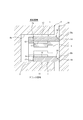
図1に示すように、本発明の一実施の形態であるサイドレール1は、スペーサエキスパンダー2とともに組合せオイルリング(オイルコントロールリング)3を構成する。図示する場合では、組合せオイルリング3は、スペーサエキスパンダー2の軸方向の両側に一対のサイドレール1を組み合わせた3ピースタイプとなっており、図2に示すように、ガソリンエンジンなどの往復動内燃機関のピストン4の外周面に形成されたリング溝4aに装着して使用される。
As shown in FIG. 1, a side rail 1 according to an embodiment of the present invention constitutes a combined oil ring (oil control ring) 3 together with a spacer expander 2. In the illustrated case, the combination oil ring 3 is a three-piece type in which a pair of side rails 1 are combined on both sides in the axial direction of the spacer expander 2, and as shown in FIG. It is used by being attached to a ring groove 4a formed on the outer peripheral surface of the piston 4 of the engine.
組合せオイルリング3は、スペーサエキスパンダー2に1つのサイドレール1のみを組み合わせた2ピースタイプとすることもできる。
The combination oil ring 3 may be a two-piece type in which only the side rail 1 is combined with the spacer expander 2.
スペーサエキスパンダー2は鋼材により径方向内外方向に向けて弾性変形自在な円環状に形成されており、縮径方向に弾性変形した状態でピストン4のリング溝4aに装着されてサイドレール1を径方向外側および軸方向外側に向けて拡径させるように付勢する。
The spacer expander 2 is formed of a steel material in an annular shape that can be elastically deformed in the radially inward and outward directions, and is elastically deformed in the diameter reducing direction and mounted on the ring groove 4a of the piston 4 to radially Energize outward and axially outward.
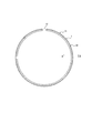
発明の一実施の形態である一対のサイドレール1は互いに同一の構成を有するものであり、図3に示すように、長尺で平板状の鋼材(スチール材)を曲げることにより、合口10を備えた割リング形状に形成されている。つまり、サイドレール1は、その周方向の一部分が切断されて当該切断部分が合口10となったC字形状に形成されている。サイドレール1は、合口10の間隔を周方向に拡大させるように弾性変形して、径方向外側に向けて拡径することができる。
The pair of side rails 1 according to the embodiment of the invention have the same configuration as each other, and as shown in FIG. 3, the joint 10 is formed by bending a long and flat steel material (steel material). It is formed in the provided split ring shape. That is, the side rail 1 is formed in a C-shape in which a part in the circumferential direction is cut and the cut portion becomes the joint 10. The side rail 1 can be elastically deformed so as to expand the interval of the joint 10 in the circumferential direction, and the diameter can be expanded radially outward.
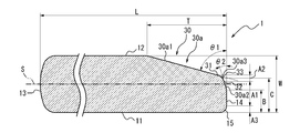
図4に示すように、このサイドレール1は、軸方向の一方側(図中下側)を向く第1の軸方向側面11、軸方向の他方側(図中上側)を向く第2の軸方向側面12、径方向内側を向く内周面13および径方向外側を向く外周面14を備えており、その周方向に垂直な断面形状は全周に亘って略一様となっている。なお、「軸方向」とは、割リング形状のサイドレール1の軸心に沿う方向である。
As shown in FIG. 4, the side rail 1 has a first axial side 11 facing one side in the axial direction (lower side in the drawing) and a second axis facing the other side (upper side in the drawing) in the axial direction. A direction side surface 12, an inner circumferential surface 13 facing inward in the radial direction, and an outer circumferential surface 14 facing outward in the radial direction are provided, and a cross-sectional shape perpendicular to the circumferential direction is substantially uniform over the entire circumference. The “axial direction” is a direction along the axial center of the split ring-shaped side rail 1.
第1の軸方向側面11は軸方向に垂直な平坦面に形成されている。図2に示すように、第1の軸方向側面11は、このサイドレール1を用いた組合せオイルリング3がピストン4に装着された状態においてエンジンのクランク室側に向けられる。
The first axial side surface 11 is formed in a flat surface perpendicular to the axial direction. As shown in FIG. 2, the first axial side surface 11 is directed to the crank chamber side of the engine in a state where the combined oil ring 3 using the side rail 1 is mounted on the piston 4.
図4に示すように、第2の軸方向側面12は軸方向に垂直つまり第1の軸方向側面11に平行な平坦面に形成されている。図2に示すように、第2の軸方向側面12は、このサイドレール1を用いた組合せオイルリング3がピストン4に装着された状態においてエンジンの燃焼室側に向けられる。
As shown in FIG. 4, the second axial side 12 is formed in a flat surface that is perpendicular to the axial direction, that is, parallel to the first axial side 11. As shown in FIG. 2, the second axial side surface 12 is directed to the combustion chamber side of the engine in a state where the combined oil ring 3 using the side rail 1 is mounted on the piston 4.
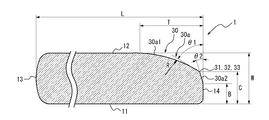
なお、図示する場合では、サイドレール1の一対の軸方向側面11、12の軸方向間隔つまりサイドレール1の軸方向厚み(レール幅)Wは0.35mm、内周面13と外周面14との間隔つまり径方向長さLは1.52mmとなっている。
In the illustrated case, the axial distance between the pair of axial side surfaces 11 and 12 of the side rail 1, that is, the axial thickness (rail width) W of the side rail 1 is 0.35 mm, and the inner peripheral surface 13 and the outer peripheral surface 14 The distance L between them, ie, the radial length L, is 1.52 mm.
図4に示すように、サイドレール1の内周面13は軸方向中心位置に頂点を有する湾曲面形状(バレルフェース)に形成されている。図2に示すように、サイドレール1の内周面13は、サイドレール1を用いた組合せオイルリング3がピストン4に装着された状態においてスペーサエキスパンダー2の座面2aに当接する。
As shown in FIG. 4, the inner circumferential surface 13 of the side rail 1 is formed in a curved surface shape (barrel face) having an apex at the axial center position. As shown in FIG. 2, the inner circumferential surface 13 of the side rail 1 abuts on the seat surface 2 a of the spacer expander 2 in a state where the combined oil ring 3 using the side rail 1 is mounted on the piston 4.
なお、内周面13は、上記形状に限らず、例えば軸方向に平行な円筒面形状など種々の形状を採用することができる。
In addition, the inner peripheral surface 13 is not limited to the above-mentioned shape, and can adopt various shapes such as a cylindrical surface shape parallel to the axial direction, for example.
図4に示すように、サイドレール1の外周面14は軸方向に平行な円筒面形状に形成されている。図2に示すように、サイドレール1は、この外周面14においてシリンダ内面20に接する。
As shown in FIG. 4, the outer peripheral surface 14 of the side rail 1 is formed in a cylindrical surface shape parallel to the axial direction. As shown in FIG. 2, the side rail 1 contacts the cylinder inner surface 20 at the outer peripheral surface 14.
このサイドレール1では、外周面14の軸方向の両端部のうち一方側の端部に面取り部30が設けられている。つまり、外周面14と第2の軸方向側面12との間に面取り部30が設けられている。なお、外周面14と第1の軸方向側面11との間は面取り部が設けられない形状に形成されてもよいが、丸みを帯びたR形状に形成されてもよく、この場合、R形状は面取り部30よりも径方向幅および軸方向幅が小さく形成される。
In the side rail 1, a chamfered portion 30 is provided at one of the two axial end portions of the outer peripheral surface 14. That is, the chamfered portion 30 is provided between the outer peripheral surface 14 and the second axial side surface 12. The outer circumferential surface 14 and the first axial side surface 11 may be formed in a shape not provided with a chamfered portion, but may be formed in a rounded R shape, in which case the R shape Are formed smaller in radial width and axial width than the chamfered portion 30.
面取り部30は、第1の軸方向側面11から第2の軸方向側面12に向けた第1の軸方向距離Bが0.05mm以上となる外周面14上の位置、つまり第1の軸方向側面11から第2の軸方向側面12に向けて軸方向に0.05mm以上離れた外周面14上の位置を起点とし、該起点から第2の軸方向側面12の側に向けて徐々に縮径しながら第2の軸方向側面12にまで延びるテーパ面30aにより形成されている。
The chamfered portion 30 is located on the outer peripheral surface 14 at which the first axial distance B from the first axial side surface 11 to the second axial side surface 12 is 0.05 mm or more, that is, the first axial direction. Starting from the position on the outer peripheral surface 14 axially separated by 0.05 mm or more from the side surface 11 to the second axial side surface 12, the position gradually shrinks from the starting point toward the second axial side surface 12. It is formed by a tapered surface 30 a that extends to the second axial side 12 while being diameter.
なお、面取り部30の起点となる第1の軸方向距離Bは、より好ましくは0.10mm以上に設定される。
The first axial distance B which is the starting point of the chamfered portion 30 is more preferably set to 0.10 mm or more.
図4に示すように、面取り部30を構成するテーパ面30aは、軸方向に対して角度θ1で傾斜する第1のテーパ面部30a1と、第1のテーパ面部30a1と外周面14との間に設けられて第1のテーパ面部30a1よりも小さい角度θ2で軸方向に対して傾斜する第2のテーパ面部30a2とを有して構成されている。なお、第1のテーパ面部30a1は、第2の軸方向側面12が位置する側の端部において、第2の軸方向側面12と連続している。また、第2のテーパ面部30a2は、第1の軸方向側面11が位置する側の端部において、外周面14と連続している。
As shown in FIG. 4, the tapered surface 30 a constituting the chamfered portion 30 is between the first tapered surface portion 30 a 1 which is inclined at an angle θ 1 with respect to the axial direction, the first tapered surface portion 30 a 1 and the outer peripheral surface 14. A second tapered surface portion 30a2 is provided and inclined with respect to the axial direction at an angle θ2 smaller than the first tapered surface portion 30a1. The first tapered surface portion 30a1 is continuous with the second axial side surface 12 at the end on which the second axial side surface 12 is located. The second tapered surface portion 30a2 is continuous with the outer peripheral surface 14 at the end on which the first axial side surface 11 is located.
第1のテーパ面部30a1が軸方向に対してなす角度θ1は、10°以上である。角度θ1を10°以上とすることで、面取り部30を面取り部30以外の箇所から識別しやすくなり、面取り部30の視認性を確保することができる。視認性確保の観点から、角度θ1を30°以上とすることが好ましい。また、第1のテーパ面部30a1が軸方向に対してなす角度θ1と、第2のテーパ面部30a2が軸方向に対してなす角度θ2と、の差は、2°以上であることが好ましい。角度θ1と角度θ2との差を2°以上とすることで、第1のテーパ面部30a1により反射される光の反射角度と、第2のテーパ面部30a2により反射される光の反射角度との差異が大きくなり、面取り部30の視認性をより高めることができる。
An angle θ1 formed by the first tapered surface portion 30a1 with respect to the axial direction is 10 ° or more. By setting the angle θ1 to 10 ° or more, the chamfered portion 30 can be easily identified from a place other than the chamfered portion 30, and the visibility of the chamfered portion 30 can be secured. From the viewpoint of securing visibility, the angle θ1 is preferably 30 ° or more. The difference between the angle θ1 formed by the first tapered surface portion 30a1 with the axial direction and the angle θ2 formed by the second tapered surface portion 30a2 with the axial direction is preferably 2 ° or more. By setting the difference between the angle θ1 and the angle θ2 to 2 ° or more, the difference between the reflection angle of light reflected by the first tapered surface portion 30a1 and the reflection angle of light reflected by the second tapered surface portion 30a2 Of the chamfered portion 30 can be further enhanced.
ところで、サイドレール1は、図2に示したピストン4のリング溝4aに装着された状態では、ピストン4の上下運動中に傾動することで、面取り部30がシリンダ内面20に衝突することがある。この衝突を緩和する観点からも、第2のテーパ面部30a2が軸方向に対してなす角度θ2を、第1のテーパ面部30a1が軸方向に対してなす角度θ1よりも2°以上小さいことが好ましい。衝突を緩和する観点から、第2のテーパ面部30a2が軸方向に対してなす角度θ2は、2°以上10°以下とすることが好ましい。また、第1のテーパ面部30a1がシリンダ内面20に衝突することを防ぐためには、第2のテーパ面部30a2の軸方向距離が0.10mm以上であることが好ましく、0.15mm以上であることがより好ましい。
By the way, in the state where the side rail 1 is attached to the ring groove 4 a of the piston 4 shown in FIG. 2, the chamfered portion 30 may collide with the cylinder inner surface 20 by tilting during the vertical movement of the piston 4. . Also from the viewpoint of alleviating this collision, it is preferable that the angle θ2 formed by the second tapered surface portion 30a2 with respect to the axial direction be smaller than the angle θ1 formed by the first tapered surface portion 30a1 with respect to the axial direction. . From the viewpoint of alleviating the collision, the angle θ2 formed by the second tapered surface portion 30a2 with respect to the axial direction is preferably 2 ° or more and 10 ° or less. Further, in order to prevent the first tapered surface portion 30a1 from colliding with the cylinder inner surface 20, the axial distance of the second tapered surface portion 30a2 is preferably 0.10 mm or more, and is preferably 0.15 mm or more. More preferable.
なお、図示する場合では、第1のテーパ面部30a1及び第2のテーパ面部30a2は、何れも、直線的に縮径する形状(円錐面形状)つまり線形テーパ面に形成されている。
In the illustrated case, each of the first tapered surface portion 30a1 and the second tapered surface portion 30a2 is formed in a shape (conical surface shape) in which the diameter is linearly reduced, that is, a linear tapered surface.
また、面取り部30つまりテーパ面30aの径方向長さTは0.05mm以上とするのが好ましい。
The radial length T of the chamfered portion 30, that is, the tapered surface 30a is preferably 0.05 mm or more.
このように、本発明のサイドレール1では、外周面14の軸方向の両端部のうち一方側の端部に視認性のある面取り部30を設けるようにしたので、面取り部30を設けることによりサイドレールが上下(表裏)の方向性を有することになっても、このサイドレール1の製造時やピストンのリング溝への組み付け作業時等において、作業者による面取り部30の目視や、例えば光学式の非接触判別装置等によって、サイドレール1の上下を容易に判別することができる。したがって、当該作業時においてサイドレール1が誤った姿勢に誤組みされることを防止することができる。
As described above, in the side rail 1 of the present invention, since the chamfered portion 30 having visibility is provided at one of the two axial end portions of the outer peripheral surface 14 in the axial direction, the chamfered portion 30 is provided. Even when the side rail has vertical (upper and lower) directionality, visual inspection of the chamfered portion 30 by a worker, for example, at the time of manufacturing the side rail 1 or assembling work to the ring groove of the piston The upper and lower sides of the side rail 1 can be easily determined by the noncontact determination device of the formula or the like. Therefore, it is possible to prevent the side rail 1 from being assembled incorrectly in the wrong posture at the time of the work.
また、面取り部30を構成するテーパ面30aを、第1のテーパ面部30a1と、第1のテーパ面部30a1よりも小さい角度θ2で軸方向に対して傾斜する第2のテーパ面部30a2とを有する構成とすることにより、面取り部30の径方向長さTを確保してその視認性を高めつつ、第2のテーパ面部30a2により外周面14に対する入射角度を低減させることができる。これにより、面取り部30にシリンダ内面20に対する外周面14のエッジによるオイル掻き上げを防止させてオイル消費を低減させることができる。なお、オイル消費を低減させる観点から、第2のテーパ面部30a2が軸方向に対してなす角度θ2は、2°以上12°以下であることが好ましく、4°以上8°以下であることがより好ましい。
Further, the tapered surface 30a constituting the chamfered portion 30 has a first tapered surface portion 30a1 and a second tapered surface portion 30a2 inclined relative to the axial direction at an angle θ2 smaller than the first tapered surface portion 30a1. By setting this, it is possible to reduce the incident angle to the outer peripheral surface 14 by the second tapered surface portion 30a2, while securing the radial length T of the chamfered portion 30 and enhancing the visibility thereof. Thereby, oil consumption can be reduced by preventing the oil scraping by the edge of the outer peripheral surface 14 with respect to the cylinder inner surface 20 in the chamfered portion 30. From the viewpoint of reducing oil consumption, the angle θ2 formed by the second tapered surface portion 30a2 with the axial direction is preferably 2 ° or more and 12 ° or less, and more preferably 4 ° or more and 8 ° or less preferable.
ところで、図4に示すように、第1のテーパ面部30a1の第1の軸方向側面11が位置する側の端部31と、第2のテーパ面部30a2の第2の軸方向側面12が位置する側の端部32と、の軸方向中心位置33から、第1の軸方向側面11までの軸方向に沿う第2の軸方向距離Cが、サイドレール1の軸方向厚みWに対して60%以上80%以下の大きさであることが好ましい。第2の軸方向距離Cを、サイドレール1の軸方向厚みWに対して80%以下とすることで、面取り部30の径方向長さTを一定以上に確保できるため、面取り部30の視認性を高めることができる。また、第2の軸方向距離Cを、サイドレール1の軸方向厚みWに対して60%以上とすることで、第2のテーパ面部30a2の領域を一定以上に確保できるため、オイル消費を低減させることができる。なお、図4に示す例では、第1のテーパ面部30a1と第2のテーパ面部30a2とが連続しているため、軸方向中心位置33は、端部31及び端部32と同じ位置である。
By the way, as shown in FIG. 4, the end 31 of the first tapered surface 30a1 on the side where the first axial side 11 is located and the second axial side 12 of the second tapered surface 30a2 are located. The second axial distance C along the axial direction from the axial center position 33 of the side end 32 to the first axial side 11 is 60% of the axial thickness W of the side rail 1 The size is preferably 80% or less. By setting the second axial distance C to 80% or less with respect to the axial thickness W of the side rail 1, the radial length T of the chamfered portion 30 can be secured at a certain level or more. Can be enhanced. Further, by setting the second axial distance C to 60% or more with respect to the axial thickness W of the side rail 1, the region of the second tapered surface portion 30a2 can be secured at a certain level or more, so oil consumption is reduced. It can be done. In the example shown in FIG. 4, since the first tapered surface portion 30 a 1 and the second tapered surface portion 30 a 2 are continuous, the axial center position 33 is the same position as the end portions 31 and 32.
図5に示すように、面取り部30を構成するテーパ面30aは、第1のテーパ面部30a1と第2のテーパ面部30a2との間に曲面状のテーパ面副部30a3を設け、このテーパ面副部30a3によって第1のテーパ面部30a1と第2のテーパ面部30a2とを滑らかに繋げた構成とすることもできる。この場合、テーパ面副部30a3は、一定の曲率半径を有する曲面状とするのが好ましいが、曲率半径が徐々に変化する曲面状とすることもできる。なお、図5に示す例では、図4に示した例と同様に、第1のテーパ面部30a1及び第2のテーパ面部30a2が、何れも、直線的に縮径する形状(円錐面形状)つまり線形テーパ面に形成されている。
As shown in FIG. 5, the tapered surface 30a constituting the chamfered portion 30 is provided with a curved tapered surface subportion 30a3 between the first tapered surface portion 30a1 and the second tapered surface portion 30a2, and this tapered surface subportion The first tapered surface portion 30a1 and the second tapered surface portion 30a2 can be smoothly connected by the portion 30a3. In this case, the tapered surface subportion 30a3 is preferably in the form of a curved surface having a constant radius of curvature, but may be in the form of a curved surface in which the radius of curvature gradually changes. In the example shown in FIG. 5, similarly to the example shown in FIG. 4, each of the first tapered surface portion 30a1 and the second tapered surface portion 30a2 has a shape (conical surface shape) that linearly reduces in diameter. It is formed in a linear taper surface.
このように、面取り部30を構成するテーパ面30aを、第1のテーパ面部30a1と第2のテーパ面部30a2との間に曲面状のテーパ面副部30a3を設けた構成とすることにより、外周面14のエッジによるオイル掻き上げをさらに効果的に防止させてオイル消費をさらに低減させることができる。
Thus, the outer peripheral surface is formed by providing the curved surface sub-portion 30a3 between the first taper surface portion 30a1 and the second taper surface portion 30a2 as the taper surface 30a constituting the chamfered portion 30. The oil scraping by the edge of the surface 14 can be more effectively prevented to further reduce the oil consumption.
なお、図5に示す例においても、図4に示した例と同様に、第1のテーパ面部30a1が軸方向に対してなす角度θ1は、10°以上であり、30°以上であることが好ましい。また、第1のテーパ面部30a1が軸方向に対してなす角度θ1と、第2のテーパ面部30a2が軸方向に対してなす角度θ2と、の差は、2°以上であることが好ましい。また、第2のテーパ面部30a2が軸方向に対してなす角度θ2は、2°以上12°以下であることが好ましい。更に、第1のテーパ面部30a1の第1の軸方向側面11が位置する側の端部31と、第2のテーパ面部30a2の第2の軸方向側面12が位置する側の端部32と、の軸方向中心位置33から、第1の軸方向側面11までの軸方向に沿う第2の軸方向距離Cが、サイドレール1の軸方向厚みWに対して60%以上80%以下の大きさであることが好ましい。なお、図5に示す例では、軸方向中心位置33は、テーパ面副部30a3の軸方向中心に位置する。
Also in the example shown in FIG. 5, similarly to the example shown in FIG. 4, the angle θ1 formed by the first tapered surface portion 30a1 with respect to the axial direction is 10 ° or more and 30 ° or more. preferable. The difference between the angle θ1 formed by the first tapered surface portion 30a1 with the axial direction and the angle θ2 formed by the second tapered surface portion 30a2 with the axial direction is preferably 2 ° or more. The angle θ2 formed by the second tapered surface portion 30a2 with respect to the axial direction is preferably 2 ° or more and 12 ° or less. Furthermore, an end 31 of the first tapered surface 30a1 on which the first axial side 11 is located, and an end 32 of the second tapered surface 30a2 on which the second axial side 12 is located; The second axial distance C along the axial direction from the axial center position 33 to the first axial side 11 is 60% to 80% of the axial thickness W of the side rail 1 Is preferred. In the example shown in FIG. 5, the axial center position 33 is located at the axial center of the tapered surface subportion 30a3.
また、図6に示すように、面取り部30の第1のテーパ面部30a1は曲面状に形成することもできる。この場合においても、第1のテーパ面部30a1は一定の曲率半径を有する曲面状とするのが好ましいが、曲率半径が徐々に変化する曲面状とすることもできる。なお、図6に示す例において、第2のテーパ面部30a2は、直線的に縮径する形状(円錐面形状)つまり線形テーパ面に形成されている。
Further, as shown in FIG. 6, the first tapered surface portion 30a1 of the chamfered portion 30 can also be formed in a curved shape. Also in this case, the first tapered surface portion 30a1 is preferably in the form of a curved surface having a constant radius of curvature, but may be in the form of a curved surface in which the radius of curvature gradually changes. In the example shown in FIG. 6, the second tapered surface portion 30a2 is formed in a shape (conical surface shape) that linearly reduces in diameter, that is, a linear tapered surface.
このように、面取り部30を曲面状の第1のテーパ面部30a1を有する構成とすることにより、面取り部30をより視認し易くして、このサイドレール1の上下判別をさらに容易にすることができる。
As described above, by forming the chamfered portion 30 with the first tapered surface portion 30a1 in a curved surface shape, the chamfered portion 30 can be more easily visually recognized, and the upper and lower side discrimination of the side rail 1 can be further facilitated. it can.
なお、図6に示す例においても、図4及び図5に示した例と同様に、第1のテーパ面部30a1が軸方向に対してなす角度θ1は、10°以上であり、30°以上であることが好ましい。また、第1のテーパ面部30a1が軸方向に対してなす角度θ1と、第2のテーパ面部30a2が軸方向に対してなす角度θ2と、の差は、2°以上であることが好ましい。また、第2のテーパ面部30a2が軸方向に対してなす角度θ2は、2°以上12°以下であることが好ましい。更に、第1のテーパ面部30a1の第1の軸方向側面11が位置する側の端部31と、第2のテーパ面部30a2の第2の軸方向側面12が位置する側の端部32と、の軸方向中心位置33から、第1の軸方向側面11までの軸方向に沿う第2の軸方向距離Cが、サイドレール1の軸方向厚みWに対して60%以上80%以下の大きさであることが好ましい。
Also in the example shown in FIG. 6, similarly to the example shown in FIGS. 4 and 5, the angle θ1 formed by the first tapered surface portion 30a1 with respect to the axial direction is 10 ° or more, and 30 ° or more. Is preferred. The difference between the angle θ1 formed by the first tapered surface portion 30a1 with the axial direction and the angle θ2 formed by the second tapered surface portion 30a2 with the axial direction is preferably 2 ° or more. The angle θ2 formed by the second tapered surface portion 30a2 with respect to the axial direction is preferably 2 ° or more and 12 ° or less. Furthermore, an end 31 of the first tapered surface 30a1 on which the first axial side 11 is located, and an end 32 of the second tapered surface 30a2 on which the second axial side 12 is located; The second axial distance C along the axial direction from the axial center position 33 to the first axial side 11 is 60% to 80% of the axial thickness W of the side rail 1 Is preferred.
ここで、図6に示すように、曲面状の第1のテーパ面部30a1が軸方向に対してなす角度θ1は、第1のテーパ面部30a1の第1の軸方向側面11が位置する側の端部31における第1のテーパ面部30a1の接線が、軸方向に対してなす角度であるとする。
Here, as shown in FIG. 6, the angle θ1 formed by the curved first taper surface portion 30a1 with respect to the axial direction is the end of the first taper surface portion 30a1 on the side where the first axial side surface 11 is located. It is assumed that the tangent of the first tapered surface portion 30a1 in the portion 31 is at an angle with respect to the axial direction.
なお、図6に示す場合では、第1のテーパ面部30a1と第2のテーパ面部30a2との間にテーパ面副部30a3は設けられていないが、第1のテーパ面部30a1と第2のテーパ面部30a2との間にテーパ面副部30a3を設けた構成とすることもできる。
In the case shown in FIG. 6, although the taper surface subportion 30a3 is not provided between the first taper surface portion 30a1 and the second taper surface portion 30a2, the first taper surface portion 30a1 and the second taper surface portion are provided. A tapered surface sub-portion 30a3 may be provided between it and 30a2.
図5に示すように、面取り部30のうち径方向外側を向く第2のテーパ面部30a2と外周面14とを合わせた領域を外周面領域A1とすると、サイドレール1の上下判別を容易にするためには、この外周面領域A1を軸方向に挟む2つの領域、すなわちテーパ面副部30a3の領域A2と、外周面14と第1の軸方向側面11との間に設けられる曲面形状の外周下端面15の領域A3とが、第1の軸方向側面11と第2の軸方向側面12との軸方向中間位置を通る仮想面Sを基準として互いに非対称形状であるのが好ましい。
As shown in FIG. 5, if the area of the chamfered portion 30 which combines the second tapered surface portion 30a2 facing outward in the radial direction and the outer peripheral surface 14 is the outer peripheral surface area A1, the upper and lower sides of the side rail 1 can be easily discriminated. For this purpose, the outer periphery of the curved surface provided between the outer peripheral surface 14 and the first axial side 11 and the two regions sandwiching the outer peripheral surface region A1 in the axial direction, that is, the region A2 of the tapered surface subportion 30a3 It is preferable that the area A3 of the lower end surface 15 is asymmetrical with respect to a virtual surface S passing through an axial intermediate position between the first axial side 11 and the second axial side 12.
この場合、サイドレール1の外周面領域A1は、軸方向について非対称形状に形成するのが好ましい。詳細は図示しないが、この非対称形状としては、以下のような形状とすることができる。すなわち、その軸方向の中心を通って軸方向に直交する線を第1中間線とし、縦断面における外周面の輪郭曲線がトレースされた外周先端部において、外周頂点から径方向の内周側に向かい距離3μmの位置における輪郭曲線上の2つの位置のうちエンジンの燃焼室側の位置を位置a1、エンジンの燃焼室から離れる側の位置を位置b1とし、それら位置a1と位置b1との間の線分の長さをL1とし、その長さL1の線分の中間線を第2中間線としたとき、第2中間線は、第1中間線よりもエンジンの燃焼室から離れる側に位置する。また、サイドレール1の外周頂点は、第2中間線上か、または第2中間線よりもエンジンの燃焼室から離れる側に位置する。また、縦断面における外周面の輪郭曲線は、径方向の内周側位置に軸方向両端側を一対とする対称形状が存在するよう、サイドレール1の外周頂点から径方向の内周側に向かって少なくとも0.025mmまでトレースされている。サイドレール1の外周先端部における非対称形状の輪郭曲線を、径方向の内周側に向かい外周頂点と外周頂点から距離1.5μmで挟まれる曲線部分と径方向の内周側に向かい外周頂点から距離1.5μmと距離3.0μmで挟まれる輪郭部分に区分し、シリンダのエンジンの燃焼室側から第1輪郭区分、第2輪郭区分、および第3輪郭区分としたとき、第1輪郭区分は第2輪郭区分のエンジンの燃焼室側の第1端部を始点として直線形状または2次曲線形状の一部に設けられる。また、第2輪郭区分は、その中途に外周頂点が存在し、弧状に設けられる。また、第3輪郭区分は、第2輪郭区分のエンジンの燃焼室から離れる側の第2端部を始点とし2次曲線形状の一部となるように設けられる。また、サイドレール1の外周面のうち非対称部分の表面粗さは0.6μmRp以下である。輪郭曲線における外周先端部のうち、位置a1と位置b1との間の線分に直交する径方向の線であって外周頂点を通る線で分割された線分L1の位置a1側の長さをL2、位置b1側の長さをL3とし、さらに径方向の内周側に向かい距離1.5μmにおける輪郭曲線上の2つの位置においてエンジンの燃焼室側の位置を位置a2、エンジンの燃焼室から離れる側の位置を位置b2とし、位置a2と位置b2との間の線分の長さをL4としたとき、0.05mm≦L1≦0.15mm、L2/L1≧0.5、L3/L1≦0.74の条件を満たす。位置a1と位置a2を通る第1直線とシリンダの軸方向とがなす角度を角度θ3としたとき、2度≦θ3≦7度の条件を満たす。位置b1と前記位置b2を通る第2直線とシリンダの軸方向とがなす角度を角度θ4としたとき、9度≦θ4の条件を満たす。
In this case, the outer peripheral surface area A1 of the side rail 1 is preferably formed in an asymmetrical shape in the axial direction. Although not shown in detail, the asymmetric shape may be as follows. That is, a line perpendicular to the axial direction through the axial center is defined as the first intermediate line, and at the outer peripheral tip where the contour curve of the outer peripheral surface in the vertical cross section is traced, from the outer peripheral vertex to the inner peripheral side in the radial direction The position on the combustion chamber side of the engine among the two positions on the contour curve at the 3 μm facing distance is a position a1, the position on the side away from the combustion chamber of the engine is a position b1, and between these positions a1 and b1. Assuming that the length of the line segment is L1 and the middle line of the line segment of the length L1 is the second middle line, the second middle line is located farther from the engine combustion chamber than the first middle line . Further, the outer circumferential apex of the side rail 1 is located on the second intermediate line or on the side farther from the engine combustion chamber than the second intermediate line. Further, the contour curve of the outer peripheral surface in the vertical cross section is directed from the outer peripheral vertex of the side rail 1 toward the inner peripheral side in the radial direction so that a symmetrical shape having the axial both end sides as a pair exists at the inner peripheral side position in the radial direction. Is traced to at least 0.025 mm. The asymmetrical contour curve at the outer peripheral tip of the side rail 1 is directed toward the inner peripheral side in the radial direction from the outer peripheral apex and the outer peripheral apex at a distance of 1.5 μm and from the outer peripheral apex toward the inner peripheral side in the radial direction The first contour division is divided into the contour portion sandwiched by the distance 1.5 μm and the distance 3.0 μm, and the first contour division, the second contour division, and the third contour division from the combustion chamber side of the engine of the cylinder Starting from a first end of the second contour section on the combustion chamber side of the engine, it is provided in part of a linear shape or a quadratic curve shape. In addition, the second contour segment has an outer circumferential vertex in the middle thereof and is provided in an arc shape. In addition, the third contour section is provided so as to be a part of a quadratic curve shape, with the second end away from the combustion chamber of the engine of the second contour section as a starting point. Further, the surface roughness of the asymmetric portion of the outer peripheral surface of the side rail 1 is 0.6 μmRp or less. The length of the position a1 side of the line segment L1 divided by the line passing through the outer peripheral vertex which is a radial line perpendicular to the line segment between the position a1 and the position b1 among the outer peripheral tip end portions in the contour curve L2, the length on the side of position b1 is L3, and the position on the combustion chamber side of the engine at two positions on the contour curve at a distance of 1.5 μm toward the inner peripheral side in the radial direction is position a2 from the combustion chamber of the engine Assuming that the position on the opposite side is a position b2, and the length of the line segment between the position a2 and the position b2 is L4, 0.05 mm ≦ L1 ≦ 0.15 mm, L2 / L1 ≧ 0.5, L3 / L1 The condition of ≦ 0.74 is satisfied. When an angle formed by a first straight line passing through the position a1 and the position a2 and the axial direction of the cylinder is an angle θ3, the condition of 2 degrees ≦ θ3 ≦ 7 degrees is satisfied. When the angle formed by the second straight line passing through the position b1 and the position b2 and the axial direction of the cylinder is an angle θ4, the condition of 9 degrees ≦ θ4 is satisfied.
または、サイドレール1の外周面領域A1の非対称形状としては、以下のような形状とすることもできる。すなわち、そのセグメント幅の中心を通る線を第1中間線とし、縦断面における外周面の輪郭曲線がトレースされた外周先端部において、外周頂点から径方向の内周側に向かい距離3μmの位置における輪郭曲線上の2つの位置のうちエンジンの燃焼室側の位置を位置a1、エンジンの燃焼室から離れる側の位置を位置b1とし、それら位置a1と位置b1との間の線分の長さをL1とし、その長さL1の線分の中間線を第2中間線としたとき、第2中間線は、第1中間線よりもエンジンの燃焼室から離れる側に位置する。また、サイドレール1の外周頂点は、第2中間線上か、または第2中間線よりもエンジンの燃焼室から離れる側に位置する。また、縦断面における外周面の輪郭曲線は、径方向の内周側位置に軸方向両端側を一対とする対称形状が存在するよう、サイドレール1の外周頂点から径方向の内周側に向かって少なくとも0.025mmまでトレースされている。サイドレール1の外周先端部における非対称形状の輪郭曲線を、径方向の内周側に向かい外周頂点と外周頂点から距離1.5μmで挟まれる曲線部分とセグメント径方向の内周側に向かい外周頂点から距離1.5μmと距離3.0μmで挟まれる輪郭部分に区分し、シリンダのエンジンの燃焼室側から第1輪郭区分、第2輪郭区分、および第3輪郭区分としたとき、第1輪郭区分は第2輪郭区分のエンジンの燃焼室側の第1端部を始点として直線形状または2次曲線形状の一部に設けられる。また、第2輪郭区分はその中途に平坦部を有し、平坦部の軸方向のエンジンの燃焼室側の端部から直線形状または2次曲線形状の一部からなり第1輪郭区分に連続した形状であり、平坦部の軸方向のエンジンの燃焼室から離れる側の端部から2次曲線形状の一部からなり第3輪郭区分に連続した形状で設けられる。また、第3輪郭区分は、第2端部に連続する2次曲線形状の一部となるように設けられる。サイドレール1の外周面のうち非対称部分の表面粗さは0.6μmRp以下である。サイドレール1の外周面の輪郭曲線における外周先端部のうち、位置a1と位置b1との間の線分に直交する径方向の線であって外周頂点を通る線で分割された線分L1の位置a1側の長さをL2、位置b1側の長さをL3とし、さらに径方向の内周側に向かい距離1.5μmにおける輪郭曲線上の2つの位置においてエンジンの燃焼室側の位置を位置a2、エンジンの燃焼室から離れる側の位置を位置b2とし、位置a2と位置b2との間の線分の長さをL4としたときおよび第2輪郭区分の平坦部の軸方向長さをL5としたとき、0.05mm≦L1≦0.15mm、L2/L1≧0.5、L4/L1≦0.76、0<L5≦0.05mmの条件を満たす。位置a1と位置a2を通る第1直線とシリンダの軸方向とがなす角度を角度θ3としたとき、3度≦θ3≦6度の条件を満たす。位置b1と位置b2を通る第2直線とシリンダの軸方向とがなす角度を角度θ4としたとき、9度≦θ4の条件を満たす。
Alternatively, the asymmetric shape of the outer peripheral surface area A1 of the side rail 1 may be as follows. That is, a line passing through the center of the segment width is taken as the first middle line, and at the outer peripheral tip end where the contour curve of the outer peripheral surface in the longitudinal section is traced, at a position 3 μm away from the outer peripheral vertex toward the inner peripheral side Of the two positions on the contour curve, the position on the combustion chamber side of the engine is the position a1, the position on the side away from the combustion chamber of the engine is the position b1, and the length of the line segment between these positions a1 and b1 is The second intermediate line is positioned on the side farther from the engine combustion chamber than the first intermediate line, where L1 is the intermediate line of the line segment of the length L1 as the second intermediate line. Further, the outer circumferential apex of the side rail 1 is located on the second intermediate line or on the side farther from the engine combustion chamber than the second intermediate line. Further, the contour curve of the outer peripheral surface in the vertical cross section is directed from the outer peripheral vertex of the side rail 1 toward the inner peripheral side in the radial direction so that a symmetrical shape having the axial both end sides as a pair exists at the inner peripheral side position in the radial direction. Is traced to at least 0.025 mm. The asymmetrical contour curve at the outer peripheral tip of the side rail 1 is directed toward the inner peripheral side in the radial direction toward the inner peripheral side of the segment radial direction with the curved portion sandwiched between the outer peripheral vertex and the outer peripheral vertex at a distance of 1.5 μm When it is divided into the contour part sandwiched by the distance 1.5 μm and the distance 3.0 μm, and the first contour division, the second contour division, and the third contour division from the combustion chamber side of the cylinder engine, the first contour division Is provided in a portion of a linear shape or a quadratic curve shape starting from a first end on the combustion chamber side of the engine of the second contour section. In addition, the second contour section has a flat portion in the middle, and is a part of a linear shape or a quadratic curve shape from the end on the combustion chamber side of the engine in the axial direction of the flat portion and is continuous to the first contour section The flat portion is provided in a shape continuous with the third contour section from the end portion of the flat portion in the axial direction away from the combustion chamber of the engine. Also, the third contour section is provided to be part of a quadratic curve shape continuous to the second end. The surface roughness of the asymmetric portion of the outer peripheral surface of the side rail 1 is 0.6 μmRp or less. Of the outer peripheral tip portion of the contour curve of the outer peripheral surface of the side rail 1, a line in the radial direction orthogonal to the line segment between the position a1 and the position b1 and divided by a line passing through the outer peripheral vertex The length on the position a1 side is L2, the length on the position b1 side is L3, and the position on the combustion chamber side of the engine at two positions on the contour curve at a distance of 1.5 μm toward the inner peripheral side in the radial direction a2, assuming that the position away from the combustion chamber of the engine is position b2, the length of the line segment between position a2 and position b2 is L4, and the axial length of the flat portion of the second contour section is L5 Assuming that the following conditions are satisfied: 0.05 mm ≦ L1 ≦ 0.15 mm, L2 / L1 / 0.5, L4 / L1 ≦ 0.76, 0 <L5 ≦ 0.05 mm. When an angle formed by a first straight line passing through the position a1 and the position a2 and the axial direction of the cylinder is an angle θ3, the condition of 3 degrees ≦ θ3 ≦ 6 degrees is satisfied. When an angle formed by a second straight line passing through the position b1 and the position b2 and the axial direction of the cylinder is an angle θ4, the condition of 9 degrees ≦ θ4 is satisfied.
外周面領域A1をこのような形状としつつテーパ面副部30a3の領域A2と外周下端面15の領域A3とを第1の軸方向側面11と第2の軸方向側面12との軸方向中間位置を通る仮想面Sを基準として互いに非対称形状とすることにより、オイル消費量を低減しつつサイドレール1の上下判別をさらに容易にすることができる。
While making the outer peripheral surface area A1 in such a shape, the area A2 of the tapered surface subportion 30a3 and the area A3 of the outer peripheral lower end surface are axially intermediate positions of the first axial side 11 and the second axial side 12 By making the shapes asymmetrical to each other with reference to the virtual surface S passing through, it is possible to further facilitate the upper / lower discrimination of the side rail 1 while reducing the oil consumption.
詳細は図示しないが、少なくとも外周面14と面取り部30つまりテーパ面30aの表面に硬質皮膜(硬質層)を設けた構成とすることもできる。硬質皮膜としては、例えば窒化処理層、PVD処理層、硬質クロムめっき処理層およびDLC層のうちの少なくとも何れか1種の層を備えた構成を採用することができる。
Although the details are not shown, a hard coating (hard layer) may be provided on at least the outer peripheral surface 14 and the chamfered portion 30, ie, the surface of the tapered surface 30a. As the hard coating, for example, a configuration provided with at least one of a nitrided layer, a PVD treated layer, a hard chromium plated layer, and a DLC layer can be adopted.
なお、「PVD処理層」とは「物理気相成長(Physical Vapor Deposition)により形成された層」を意味し、「DLC(Diamond Like Carbon)層」とは主として炭化水素や炭素の同素体から成る非晶質の硬質炭素膜を意味する。
Note that "PVD-treated layer" means "layer formed by physical vapor deposition (Physical Vapor Deposition)", and "DLC (Diamond Like Carbon) layer" means a non-hydrocarbon or carbon allotrope mainly. Amorphous hard carbon film is meant.
このような硬質皮膜を設けることにより、外周面14の摩耗による形状変化がなく、外周面形状が維持され、面圧減少も少なく、オイルコントロール機能が持続され、長期間に亘ってオイル消費量を低減しつつエンジンの燃費を低減する効果を得ることができるとともに、目視により視認される面取り部30の色相を、第2の軸方向側面12や外周面14に対してより鮮明に変えることができる。特に、外周面14にラッピング加工を施した場合には、その色相の差はより大きくなる。したがって、当該硬質皮膜を設けることにより、この面取り部30をより視認し易くして、このサイドレール1の上下判別をさらに容易にすることができる。
By providing such a hard film, there is no change in the shape of the outer peripheral surface 14 due to wear, the outer peripheral surface shape is maintained, the decrease in contact pressure is small, the oil control function is maintained, and oil consumption is maintained for a long time. While being able to obtain the effect of reducing the fuel consumption of the engine while reducing it, the hue of the chamfered portion 30 visually recognized can be changed more clearly with respect to the second axial side surface 12 and the outer peripheral surface 14 . In particular, when the outer peripheral surface 14 is subjected to lapping, the difference in hue becomes larger. Therefore, by providing the hard film, the chamfered portion 30 can be more easily visually recognized, and the upper and lower discrimination of the side rail 1 can be further facilitated.
(実施例1)
図4に示す形状を有するとともに、軸方向厚み(W)が0.35mm、面取り部の面取り位置を示す第1の軸方向距離(B)が0.15mm、面取り部の第1のテーパ面部の軸方向に対する角度(θ1)が30°、第2のテーパ面部の軸方向に対する角度(θ2)が6°とされた100本のサイドレールを用意し、作業者10名によりこれらのサイドレールの目視での上下の方向判別を実施した。その結果、全てのサイドレールについて作業者は、その上下の方向性を正しく判別することができた。 Example 1
4 with an axial thickness (W) of 0.35 mm, a first axial distance (B) indicating the chamfered position of the chamfered portion of 0.15 mm, and a first tapered surface portion of the chamferedportion Prepare 100 side rails with an angle (θ1) to the axial direction of 30 ° and an angle (θ2) to the axial direction of the second tapered surface part of 6 °, and visually check these side rails by 10 workers. The upper and lower direction discrimination in. As a result, the workers were able to correctly determine the upper and lower directionality of all side rails.
図4に示す形状を有するとともに、軸方向厚み(W)が0.35mm、面取り部の面取り位置を示す第1の軸方向距離(B)が0.15mm、面取り部の第1のテーパ面部の軸方向に対する角度(θ1)が30°、第2のテーパ面部の軸方向に対する角度(θ2)が6°とされた100本のサイドレールを用意し、作業者10名によりこれらのサイドレールの目視での上下の方向判別を実施した。その結果、全てのサイドレールについて作業者は、その上下の方向性を正しく判別することができた。 Example 1
4 with an axial thickness (W) of 0.35 mm, a first axial distance (B) indicating the chamfered position of the chamfered portion of 0.15 mm, and a first tapered surface portion of the chamfered
(実施例2)
図4に示す形状を有するとともに、軸方向厚み(W)が0.35mm、径方向長さ(L)が1.62mm、面取り部の面取り位置を示す第1の軸方向距離(B)が0.15mm、第2の軸方向距離(C)が軸方向厚み(W)の67%、すなわち0.23mm、面取り部の第1のテーパ面部の軸方向に対する角度(θ1)が15°とされた複数のサイドレールを用意した。これら複数のサイドレールの第2のテーパ面部の軸方向に対する角度(θ2)は、それぞれ異なる角度とした。 (Example 2)
While having the shape shown in FIG. 4, the axial thickness (W) is 0.35 mm, the radial length (L) is 1.62 mm, and the first axial distance (B) indicating the chamfer position of the chamfer is 0 .15 mm, the second axial distance (C) is 67% of the axial thickness (W), that is, 0.23 mm, and the angle (θ1) of the first tapered surface of the chamfer to the axial direction is 15 ° We prepared several side rails. The angles (θ2) of the second tapered surface portions of the plurality of side rails with respect to the axial direction are respectively different angles.
作業者10名により、これら複数のサイドレールの目視での上下の方向判別を実施した。その結果、作業者は、第1のテーパ面部の軸方向に対する角度(θ1)と第2のテーパ面部の軸方向に対する角度(θ2)との差が、2°以上のときは100本中100本全てのサイドレールについて正しく判別でき、2°未満のときは100本中3本のサイドレールについて誤って判別した。すなわち、作業者は、サイドレールの第2のテーパ面部の軸方向に対する角度(θ2)が、第1のテーパ面部の軸方向に対する角度(θ1)よりも2°以上小さくなると、サイドレールの上下の方向性をより正しく判別することができた。
The top and bottom directions of these side rails were visually checked by 10 workers. As a result, when the difference between the angle (.theta.1) of the first tapered surface with respect to the axial direction and the angle (.theta.2) of the second tapered surface with respect to the axial direction is 100.degree. It was able to discriminate correctly about all the side rails, and when less than 2 degrees, it discriminate | determined accidentally about 3 of 100 side rails. That is, if the angle (θ2) of the second tapered surface of the side rail with respect to the axial direction of the side rail is smaller than the angle (θ1) of the first tapered surface with respect to the axial direction, I could determine the direction more correctly.
(実施例3)
実施例2で用いた複数のサイドレールによりそれぞれ構成した複数の組合せオイルリングを作製した。作製した複数の組合せオイルリングをそれぞれのリング溝に装着した複数のピストンを用意し、シリンダ内で所定回数往復運動させたときの、オイル消費量を計測した。具体的には、水冷4サイクルの過給器付ガソリンエンジン(排気量2.0L、4気筒)を用いて、6000rpm、全負荷(WOT:Wide Open Throttle)条件にて所定時間運転したときのオイル消費量を計測した。なお、各計測において、後述する対比例と共通のトップリング及びセカンドリングを用いた。図7は、本実施例における、第2のテーパ面部の軸方向に対する角度(θ2)と、オイル消費量比との関係を示すグラフである。ここで、オイル消費量比は、対比例として、外周面を軸方向中心位置に頂点を有する湾曲面形状(バレルフェース)に形成したサイドレールを用いた場合のオイル消費量を100としたときの、計測されたオイル消費量である。図7に示すように、第2のテーパ面部の軸方向に対する角度(θ2)は、2°以上12°以下であればオイル消費量を低減でき、4°以上8°以下であれば、オイル消費量をより低減できることが分かった。また、第2のテーパ面部の軸方向に対する角度(θ2)が2°以上12°以下の場合、シリンダ内面に傷がついたことは確認されなかったため、面取り部のシリンダ内面への衝突が緩和されたと考えられる。 (Example 3)
A plurality of combined oil rings each made up of the plurality of side rails used in Example 2 were produced. A plurality of pistons were prepared in which a plurality of combined oil rings manufactured were attached to each ring groove, and the amount of oil consumption was measured when reciprocating a predetermined number of times in a cylinder. Specifically, using a water-cooled 4-cycle gasoline engine with a supercharger (displacement 2.0 L, 4 cylinders), the oil when operated for a specified period of time under conditions of 6000 rpm and full load (WOT: Wide Open Throttle) Consumption was measured. In addition, in each measurement, the top ring and second ring which are common with the comparative example mentioned later were used. FIG. 7 is a graph showing the relationship between the angle (θ2) of the second tapered surface with respect to the axial direction and the oil consumption ratio in this embodiment. Here, as a comparative example, the oil consumption ratio is assumed to be 100 where the oil consumption when using the side rail formed in a curved surface shape (barrel face) having an apex at the axial center position in the outer peripheral surface is 100. , The measured oil consumption. As shown in FIG. 7, the oil consumption can be reduced if the angle (θ2) of the second tapered surface with respect to the axial direction is 2 ° or more and 12 ° or less, and if 4 ° or more and 8 ° or less, the oil consumption It was found that the amount could be further reduced. Further, when the angle (θ2) of the second tapered surface with respect to the axial direction is 2 ° or more and 12 ° or less, it is not confirmed that the inner surface of the cylinder is scratched, so that the collision of the chamfer with the inner surface of the cylinder is alleviated. It is thought that
本発明は前記実施の形態に限定されるものではなく、その要旨を逸脱しない範囲で種々変更可能であることはいうまでもない。
It is needless to say that the present invention is not limited to the above embodiment, and various modifications can be made without departing from the scope of the invention.
例えば、前記実施の形態では、外周面14を軸方向に平行な円筒面形状としているが、外周面14を微小な形状変化を有する上下(表裏)非対称形状などの他の形状に形成することもできる。
For example, although the outer peripheral surface 14 is formed in a cylindrical surface shape parallel to the axial direction in the above embodiment, the outer peripheral surface 14 may be formed in other shapes such as upper and lower (front and back) asymmetric shapes having a slight shape change. it can.
1 サイドレール
2 スペーサエキスパンダー
2a 座面
3 組合せオイルリング
4 ピストン
4a リング溝
10 合口
11 第1の軸方向側面
12 第2の軸方向側面
13 内周面
14 外周面
15 外周下端面
20 シリンダ内面
30 面取り部
30a テーパ面
30a1 第1のテーパ面部
30a2 第2のテーパ面部
30a3 テーパ面副部
31 第1のテーパ面部の第1の軸方向側面が位置する側の端部
32 第2のテーパ面部の第2の軸方向側面が位置する側の端部
33 軸方向中心位置
W 軸方向厚み
L 径方向長さ
B 第1の軸方向距離
C 第2の軸方向距離
θ 角度
T 径方向長さ
θ1 角度
θ2 角度
A1 外周面領域
A2 テーパ面副部の領域
A3 外周下端面の領域
S 仮想面 DESCRIPTION OFSYMBOLS 1 side rail 2 spacer expander 2a seat 3 combination oil ring 4 piston 4a ring groove 10 joint 11 first axial side 12 second axial side 13 inner circumferential surface 14 outer circumferential surface 15 outer circumferential lower end surface 20 cylinder inner surface 30 chamfered Portion 30a Tapered surface 30a1 First tapered surface portion 30a2 Second tapered surface portion 30a3 Tapered surface sub-portion 31 End portion 32 of the first tapered surface portion on which the first axial side face is located Second portion of the second tapered surface portion End on which the axial side face is located 33 axial center position W axial thickness L radial length B first axial distance C second axial distance θ angle T radial length θ1 angle θ2 angle A1 Outer peripheral surface area A2 area of tapered surface subportion A3 area of outer peripheral lower end surface S virtual surface
2 スペーサエキスパンダー
2a 座面
3 組合せオイルリング
4 ピストン
4a リング溝
10 合口
11 第1の軸方向側面
12 第2の軸方向側面
13 内周面
14 外周面
15 外周下端面
20 シリンダ内面
30 面取り部
30a テーパ面
30a1 第1のテーパ面部
30a2 第2のテーパ面部
30a3 テーパ面副部
31 第1のテーパ面部の第1の軸方向側面が位置する側の端部
32 第2のテーパ面部の第2の軸方向側面が位置する側の端部
33 軸方向中心位置
W 軸方向厚み
L 径方向長さ
B 第1の軸方向距離
C 第2の軸方向距離
θ 角度
T 径方向長さ
θ1 角度
θ2 角度
A1 外周面領域
A2 テーパ面副部の領域
A3 外周下端面の領域
S 仮想面 DESCRIPTION OF
Claims (8)
- 合口を備えた割りリング形状に形成され、円環状のスペーサエキスパンダーに組み合わされて該スペーサエキスパンダーとともに内燃機関用の組合せオイルリングを構成するサイドレールであって、
径方向外側を向く外周面と、
径方向内側を向く内周面と、
軸方向の一方側を向く第1の軸方向側面と、
軸方向の他方側を向くとともに前記第1の軸方向側面と平行な第2の軸方向側面とを有し、
前記外周面が、前記第2の軸方向側面との間に面取り部を有し、
前記面取り部が、前記第1の軸方向側面から前記第2の軸方向側面に向けて軸方向に0.05mm以上離れた前記外周面上の位置を起点として前記第2の軸方向側面の側に向けて徐々に縮径するテーパ面により形成され、
前記テーパ面が、軸方向に対してなす角度が10°以上である第1のテーパ面部と、該第1のテーパ面部と前記外周面との間に設けられ、前記第1のテーパ面部よりも軸方向に対する傾斜角度が小さい第2のテーパ面部と、を有することを特徴とするサイドレール。 A side rail which is formed in a split ring shape having a joint and which is combined with an annular spacer expander to constitute a combined oil ring for an internal combustion engine together with the spacer expander,
An outer circumferential surface facing radially outward,
An inner circumferential surface facing radially inward,
A first axial side facing towards one side in the axial direction,
A second axial side facing the other axial side and parallel to the first axial side;
The outer peripheral surface has a chamfered portion between the outer peripheral surface and the second axial side surface;
The side of the second axial side with the chamfered portion starting from a position on the outer circumferential surface axially separated by 0.05 mm or more from the first axial side to the second axial side Formed by a tapered surface that gradually reduces in diameter toward the
The tapered surface is provided between a first tapered surface portion having an angle of 10 ° or more with respect to the axial direction, the first tapered surface portion and the outer peripheral surface, and the first tapered surface portion is more than the first tapered surface portion. And a second tapered surface portion having a small inclination angle with respect to the axial direction. - 前記第1のテーパ面部が軸方向に対してなす角度と、前記第2のテーパ面部が軸方向に対してなす角度と、の差が2°以上であることを特徴とする請求項1に記載のサイドレール。 The difference between the angle formed by the first tapered surface with respect to the axial direction and the angle formed by the second tapered surface with respect to the axial direction is 2 ° or more. Side rail.
- 前記第2のテーパ面部が軸方向に対してなす角度が2°以上12°以下であることを特徴とする請求項1又は2に記載のサイドレール。 The side rail according to claim 1, wherein an angle formed by the second tapered surface portion with respect to the axial direction is 2 ° or more and 12 ° or less.
- 前記第1のテーパ面部の前記第1の軸方向側面が位置する側の端部と、前記第2のテーパ面部の前記第2の軸方向側面が位置する側の端部と、の軸方向中心位置から、前記第1の軸方向側面までの軸方向に沿う距離が、前記サイドレールの軸方向厚みに対して60%以上80%以下の大きさであることを特徴とする請求項1から3のいずれか一項に記載のサイドレール。 The axial center of the end on the side where the first axial side of the first tapered surface is located and the end on the side where the second axial side of the second tapered surface is located The axial distance from the position to the first axial side is in the range of 60% to 80% of the axial thickness of the side rail. Side rail according to any one of the above.
- 前記第1のテーパ面部と前記第2のテーパ面部とが曲面状のテーパ面副部によって滑らかに繋げられていることを特徴とする請求項1から4のいずれか一項に記載のサイドレール。 The side rail according to any one of claims 1 to 4, wherein the first tapered surface portion and the second tapered surface portion are smoothly connected by a curved tapered surface subportion.
- 前記外周面と前記第2のテーパ面部とを合わせた領域を外周面領域としたときに、該外周面領域を軸方向に挟むように設けられた、前記テーパ面副部の領域及び前記外周面と前記第1の軸方向側面との間に設けられる曲面形状の外周下端面の領域とが、前記第1の軸方向側面と前記第2の軸方向側面との軸方向中間位置を通る仮想面を基準として互いに非対称形状であることを特徴とする請求項5に記載のサイドレール。 A region of the tapered surface subportion provided so as to sandwich the outer peripheral surface region in the axial direction when the region obtained by combining the outer peripheral surface and the second tapered surface portion is an outer peripheral surface region, and the outer peripheral surface And a region of the outer peripheral lower end surface of the curved surface shape provided between the first axial side and a virtual surface passing an axial intermediate position between the first axial side and the second axial side The side rails according to claim 5, wherein the side rails are asymmetrical with respect to each other.
- 前記第1のテーパ面部が曲面状に形成されていることを特徴とする請求項1から6のいずれか一項に記載のサイドレール。 The side rail according to any one of claims 1 to 6, wherein the first tapered surface portion is formed in a curved shape.
- 前記外周面及び前記面取り部の表面に硬質皮膜が設けられていることを特徴とする請求項1から7のいずれか一項に記載のサイドレール。 The hard coating is provided in the surface of the said outer peripheral surface and the said chamfer, The side rail as described in any one of Claim 1 to 7 characterized by the above-mentioned.
Priority Applications (5)
| Application Number | Priority Date | Filing Date | Title |
|---|---|---|---|
| EP18865205.1A EP3677764B1 (en) | 2017-10-05 | 2018-09-25 | Side rail |
| CN201880063554.2A CN111148893B (en) | 2017-10-05 | 2018-09-25 | Side rail |
| KR1020207009765A KR20200080229A (en) | 2017-10-05 | 2018-09-25 | Side rail |
| US16/652,071 US11448317B2 (en) | 2017-10-05 | 2018-09-25 | Side rail |
| KR1020227012712A KR20220053049A (en) | 2017-10-05 | 2018-09-25 | Side rail |
Applications Claiming Priority (2)
| Application Number | Priority Date | Filing Date | Title |
|---|---|---|---|
| JP2017195287A JP6603284B2 (en) | 2017-10-05 | 2017-10-05 | side rail |
| JP2017-195287 | 2017-10-05 |
Publications (1)
| Publication Number | Publication Date |
|---|---|
| WO2019069748A1 true WO2019069748A1 (en) | 2019-04-11 |
Family
ID=65994675
Family Applications (1)
| Application Number | Title | Priority Date | Filing Date |
|---|---|---|---|
| PCT/JP2018/035483 WO2019069748A1 (en) | 2017-10-05 | 2018-09-25 | Side rail |
Country Status (6)
| Country | Link |
|---|---|
| US (1) | US11448317B2 (en) |
| EP (1) | EP3677764B1 (en) |
| JP (1) | JP6603284B2 (en) |
| KR (2) | KR20200080229A (en) |
| CN (1) | CN111148893B (en) |
| WO (1) | WO2019069748A1 (en) |
Cited By (1)
| Publication number | Priority date | Publication date | Assignee | Title |
|---|---|---|---|---|
| WO2023013265A1 (en) * | 2021-08-05 | 2023-02-09 | Tpr株式会社 | Oil ring |
Families Citing this family (1)
| Publication number | Priority date | Publication date | Assignee | Title |
|---|---|---|---|---|
| JP7116861B1 (en) * | 2021-03-31 | 2022-08-10 | 株式会社リケン | Side rail and oil control ring provided with same |
Citations (8)
| Publication number | Priority date | Publication date | Assignee | Title |
|---|---|---|---|---|
| JPS5763951U (en) * | 1980-10-03 | 1982-04-16 | ||
| JPS5833276B2 (en) | 1978-09-13 | 1983-07-19 | コンポザン・アンダストリアリゼ・デユ・バテイモン・パ−ル・アブレヴイアシオン・セ−・イ−・ベ− | Polymer-containing bituminous compositions |
| JPH051062U (en) * | 1991-06-21 | 1993-01-08 | 日野自動車工業株式会社 | Piston ring mating structure |
| JP2003049705A (en) * | 2001-08-03 | 2003-02-21 | Nippon Piston Ring Co Ltd | One-ring structured piston for internal combustion engine |
| JP2003194222A (en) | 2001-12-28 | 2003-07-09 | Riken Corp | Side rail and combinational oil ring |
| JP2016035326A (en) * | 2014-07-31 | 2016-03-17 | 日本ピストンリング株式会社 | Combined oil ring |
| JP2016156411A (en) * | 2015-02-23 | 2016-09-01 | 株式会社リケン | Side rail |
| JP2016169791A (en) * | 2015-03-12 | 2016-09-23 | 株式会社リケン | Side rail |
Family Cites Families (23)
| Publication number | Priority date | Publication date | Assignee | Title |
|---|---|---|---|---|
| US2905512A (en) * | 1958-04-24 | 1959-09-22 | Ramsey Corp | Coated piston ring |
| US4497497A (en) * | 1984-06-21 | 1985-02-05 | Allis-Chalmers Corp. | Oil ring assembly with annular expander spring |
| JPH04117956U (en) * | 1991-04-04 | 1992-10-22 | 帝国ピストンリング株式会社 | combination oil ring |
| JP2003113940A (en) * | 2001-08-02 | 2003-04-18 | Riken Corp | Steel piston ring |
| DE60326055D1 (en) * | 2002-10-29 | 2009-03-19 | Toyota Motor Co Ltd | OIL RING |
| CN100410569C (en) * | 2002-10-29 | 2008-08-13 | 丰田自动车株式会社 | Oil ring |
| JP4322500B2 (en) * | 2002-12-18 | 2009-09-02 | 帝国ピストンリング株式会社 | Combination oil ring |
| CN102639851B (en) * | 2009-11-30 | 2015-08-12 | 日本活塞环株式会社 | Piston ring |
| CN102859241B (en) * | 2010-04-19 | 2015-07-15 | 日本活塞环株式会社 | Oil ring for internal combustion engine |
| WO2011151927A1 (en) * | 2010-06-04 | 2011-12-08 | 日本ピストンリング株式会社 | Oil ring for internal combustion engine |
| US8640314B2 (en) * | 2010-08-03 | 2014-02-04 | Federal-Mogul Corporation | Piston assembly transportation and installation apparatus and methods of transporting and installing a piston assembly therewith |
| DE102011120145A1 (en) * | 2010-12-24 | 2012-06-28 | Mahle International Gmbh | Piston ring for a piston of an internal combustion engine and method for its production |
| WO2012118036A1 (en) * | 2011-02-28 | 2012-09-07 | 日本ピストンリング株式会社 | Piston ring |
| JP5564082B2 (en) * | 2012-08-09 | 2014-07-30 | 株式会社リケン | Tapered face type pressure ring wire and tapered face type pressure ring |
| CN203962189U (en) | 2013-11-19 | 2014-11-26 | 浙江吉利汽车研究院有限公司 | A kind of oil ring of piston of automobile engine |
| WO2015101938A1 (en) * | 2013-12-30 | 2015-07-09 | Mahle International Gmbh | Oil control ring assembly |
| US20160040622A1 (en) * | 2014-08-05 | 2016-02-11 | General Electric Company | Piston assembly for a reciprocating engine |
| US20160040780A1 (en) * | 2014-08-05 | 2016-02-11 | General Electric Company | Piston assembly for a reciprocating engine |
| JP5833276B1 (en) | 2014-09-12 | 2015-12-16 | Tpr株式会社 | Combination oil ring |
| KR101665491B1 (en) * | 2014-09-12 | 2016-10-12 | 티피알 가부시키가이샤 | Combined oil ring |
| CN204082367U (en) * | 2014-09-24 | 2015-01-07 | 仪征威龙发动机零部件有限公司 | A kind of low oil consumption piston ring oil ring |
| JP6762657B2 (en) | 2016-04-06 | 2020-09-30 | 株式会社リケン | side rail |
| CN109416124B (en) * | 2017-07-05 | 2020-04-14 | 帝伯爱尔株式会社 | Combined oil ring |
-
2017
- 2017-10-05 JP JP2017195287A patent/JP6603284B2/en active Active
-
2018
- 2018-09-25 WO PCT/JP2018/035483 patent/WO2019069748A1/en unknown
- 2018-09-25 KR KR1020207009765A patent/KR20200080229A/en not_active IP Right Cessation
- 2018-09-25 EP EP18865205.1A patent/EP3677764B1/en active Active
- 2018-09-25 CN CN201880063554.2A patent/CN111148893B/en active Active
- 2018-09-25 US US16/652,071 patent/US11448317B2/en active Active
- 2018-09-25 KR KR1020227012712A patent/KR20220053049A/en not_active Application Discontinuation
Patent Citations (8)
| Publication number | Priority date | Publication date | Assignee | Title |
|---|---|---|---|---|
| JPS5833276B2 (en) | 1978-09-13 | 1983-07-19 | コンポザン・アンダストリアリゼ・デユ・バテイモン・パ−ル・アブレヴイアシオン・セ−・イ−・ベ− | Polymer-containing bituminous compositions |
| JPS5763951U (en) * | 1980-10-03 | 1982-04-16 | ||
| JPH051062U (en) * | 1991-06-21 | 1993-01-08 | 日野自動車工業株式会社 | Piston ring mating structure |
| JP2003049705A (en) * | 2001-08-03 | 2003-02-21 | Nippon Piston Ring Co Ltd | One-ring structured piston for internal combustion engine |
| JP2003194222A (en) | 2001-12-28 | 2003-07-09 | Riken Corp | Side rail and combinational oil ring |
| JP2016035326A (en) * | 2014-07-31 | 2016-03-17 | 日本ピストンリング株式会社 | Combined oil ring |
| JP2016156411A (en) * | 2015-02-23 | 2016-09-01 | 株式会社リケン | Side rail |
| JP2016169791A (en) * | 2015-03-12 | 2016-09-23 | 株式会社リケン | Side rail |
Non-Patent Citations (1)
| Title |
|---|
| See also references of EP3677764A4 |
Cited By (3)
| Publication number | Priority date | Publication date | Assignee | Title |
|---|---|---|---|---|
| WO2023013265A1 (en) * | 2021-08-05 | 2023-02-09 | Tpr株式会社 | Oil ring |
| JP7224404B1 (en) | 2021-08-05 | 2023-02-17 | Tpr株式会社 | oil ring |
| JP2023026722A (en) * | 2021-08-05 | 2023-02-28 | Tpr株式会社 | oil ring |
Also Published As
| Publication number | Publication date |
|---|---|
| CN111148893B (en) | 2022-08-30 |
| EP3677764A4 (en) | 2020-10-28 |
| US11448317B2 (en) | 2022-09-20 |
| US20200248808A1 (en) | 2020-08-06 |
| JP2019065830A (en) | 2019-04-25 |
| EP3677764B1 (en) | 2022-11-02 |
| KR20200080229A (en) | 2020-07-06 |
| CN111148893A (en) | 2020-05-12 |
| KR20220053049A (en) | 2022-04-28 |
| JP6603284B2 (en) | 2019-11-06 |
| EP3677764A1 (en) | 2020-07-08 |
Similar Documents
| Publication | Publication Date | Title |
|---|---|---|
| JP6530200B2 (en) | side rail | |
| JP6533670B2 (en) | side rail | |
| US10724636B2 (en) | Combined oil ring | |
| US10352445B2 (en) | Piston ring | |
| WO2019069748A1 (en) | Side rail | |
| EP3043054B1 (en) | Cuff-ring for a cylinder liner | |
| JP6762657B2 (en) | side rail | |
| JPWO2020158949A1 (en) | Combination oil ring | |
| WO2016092776A1 (en) | Oil ring | |
| JP6467222B2 (en) | Combination oil ring | |
| WO2018198173A1 (en) | Side rail | |
| CN107835909B (en) | Compression ring for internal combustion engine | |
| JP6659892B2 (en) | side rail | |
| JP7307778B2 (en) | Combination of piston rings and internal combustion engine | |
| JP6491286B2 (en) | Oil ring | |
| WO2019142668A1 (en) | Oil ring | |
| JP6438679B2 (en) | Oil ring |
Legal Events
| Date | Code | Title | Description |
|---|---|---|---|
| 121 | Ep: the epo has been informed by wipo that ep was designated in this application |
Ref document number: 18865205 Country of ref document: EP Kind code of ref document: A1 |
|
| NENP | Non-entry into the national phase |
Ref country code: DE |
|
| ENP | Entry into the national phase |
Ref document number: 2018865205 Country of ref document: EP Effective date: 20200402 |