EP3677764B1 - Side rail - Google Patents
Side rail Download PDFInfo
- Publication number
- EP3677764B1 EP3677764B1 EP18865205.1A EP18865205A EP3677764B1 EP 3677764 B1 EP3677764 B1 EP 3677764B1 EP 18865205 A EP18865205 A EP 18865205A EP 3677764 B1 EP3677764 B1 EP 3677764B1
- Authority
- EP
- European Patent Office
- Prior art keywords
- axial
- outer peripheral
- tapered surface
- axial direction
- tapered
- Prior art date
- Legal status (The legal status is an assumption and is not a legal conclusion. Google has not performed a legal analysis and makes no representation as to the accuracy of the status listed.)
- Active
Links
Images
Classifications
-
- F—MECHANICAL ENGINEERING; LIGHTING; HEATING; WEAPONS; BLASTING
- F16—ENGINEERING ELEMENTS AND UNITS; GENERAL MEASURES FOR PRODUCING AND MAINTAINING EFFECTIVE FUNCTIONING OF MACHINES OR INSTALLATIONS; THERMAL INSULATION IN GENERAL
- F16J—PISTONS; CYLINDERS; SEALINGS
- F16J9/00—Piston-rings, e.g. non-metallic piston-rings, seats therefor; Ring sealings of similar construction
- F16J9/06—Piston-rings, e.g. non-metallic piston-rings, seats therefor; Ring sealings of similar construction using separate springs or elastic elements expanding the rings; Springs therefor ; Expansion by wedging
- F16J9/064—Rings with a flat annular side rail
- F16J9/066—Spring expander from sheet metal
- F16J9/068—Spring expander from sheet metal corrugated in the axial direction
-
- F—MECHANICAL ENGINEERING; LIGHTING; HEATING; WEAPONS; BLASTING
- F02—COMBUSTION ENGINES; HOT-GAS OR COMBUSTION-PRODUCT ENGINE PLANTS
- F02F—CYLINDERS, PISTONS OR CASINGS, FOR COMBUSTION ENGINES; ARRANGEMENTS OF SEALINGS IN COMBUSTION ENGINES
- F02F5/00—Piston rings, e.g. associated with piston crown
-
- F—MECHANICAL ENGINEERING; LIGHTING; HEATING; WEAPONS; BLASTING
- F16—ENGINEERING ELEMENTS AND UNITS; GENERAL MEASURES FOR PRODUCING AND MAINTAINING EFFECTIVE FUNCTIONING OF MACHINES OR INSTALLATIONS; THERMAL INSULATION IN GENERAL
- F16J—PISTONS; CYLINDERS; SEALINGS
- F16J9/00—Piston-rings, e.g. non-metallic piston-rings, seats therefor; Ring sealings of similar construction
- F16J9/12—Details
- F16J9/20—Rings with special cross-section; Oil-scraping rings
Definitions
- This disclosure relates to a side rail that is combined with an annular space expander and constitutes, together with the space expander, a multi-piece oil ring used in an internal combustion engine.
- an oil ring configured to control oil on a cylinder inner surface is installed in a piston of a reciprocating engine (a reciprocated internal combustion engine).
- a reciprocating engine a reciprocated internal combustion engine
- a multi-piece oil ring formed by combining one side rail or a pair of side rails with an annular space expander has been popularly used.
- the side rail used for a multi-piece oil ring is formed in a split ring shape with an opening.
- the outer peripheral surface of the side rail comes in contact with the cylinder inner surface with a predetermined contact pressure (a surface pressure).
- a surface pressure a predetermined contact pressure
- the outer peripheral surface of the side rail slides on the cylinder inner surface, forming an oil film with an appropriate thickness on the cylinder inner surface and scraping off excess oil adhered to the cylinder inner surface toward a crankcase to prevent the oil from climbing up.
- Patent Literature (PLT) 1 describes a side rail having an outer peripheral surface facing radially outward formed in a curved surface having a vertex at its axial center and protruding radially outward.
- the outer peripheral surface of the side rail has been formed in a vertically (in front and back sides) asymmetrical shape with slight changes in shape.
- PLT 2 describes a side rail that includes an outer peripheral surface having an asymmetrical area including an outer peripheral vertex and being asymmetrical with respect to the axial direction and a pair of symmetrical areas that are provided on both sides across the asymmetrical area and being symmetrical to each other with respect to the axial direction.
- PLT 3 discloses a side rail according to the preamble of appended claim 1, that comprises a chamfered part that is formed from a tapered surface of which the diameter is gradually reduced towards the side of an axial side face.
- PLT 4 discloses a side rail that comprises a tapered part arranged between an axial side surface and an outer circumferential surface. Further examples of side rails are disclosed in PTL 5 and PTL 6.
- the outer peripheral surface formed in a vertically asymmetrical shape with slight shape changes as described above causes distinction between top and bottom (front and back) directions of the side rail to be difficult. Therefore, there is a problem that the side rail is assembled in a wrong direction during production of side rails or mounting of a piston into a ring groove.
- a disclosed side rail is formed in a split ring shape with an opening.
- the side rail is suitable for combining with an annular space expander and forms, together with the annular space expander, a multi-piece oil ring for use in an internal combustion engine.
- the side rail includes an outer peripheral surface facing radially outward, an inner peripheral surface facing radially inward, a first axial side surface facing one side in an axial direction, and a second axial side surface facing the other side in the axial direction and being in parallel with the first axial side surface, wherein a beveled portion is provided between the outer peripheral surface and the second axial side surface, and the beveled portion is formed in a tapered surface having a diameter gradually decreasing from a position on the outer peripheral surface toward the second axial side surface, the position being 0.05 mm or more away from the first axial side surface toward the second axial side surface in the axial direction, characterized in that: the tapered surface has a first tapered surface portion that is continuous to the second axial side surface at an end on the side where the second axial side surface is located, has a conical surface shape, and has an angle of inclination of 10° or more to the axial direction, and a second tapered surface portion that is provided between the first tapered surface portion and the outer peripheral surface
- the "split ring shape with an opening” refers to an oil ring with a portion thereof cut out in the circumferential direction and formed in a C-shape having an opening, which is the cut-off portion.
- the "axial direction” refers to a direction along an axis of the side rail in a split ring shape.
- a difference between an angle of the first tapered surface portion to the axial direction and an angle of the second tapered surface portion to the axial direction is preferably 2° or more.
- a distance along the axial direction from an axial center position between an end on a side where the first axial side surface of the first tapered surface portion is located and an end on a side where the second axial side surface of the second tapered surface portion is located to the first axial side surface is preferably 60% or more and 80% or less of an axial thickness of the side rail.
- an area of the tapered surface subportion and an area of an outer peripheral lower end surface in a curved shape provided between the outer peripheral surface and the first axial side surface, these areas being provided so as to sandwich the outer peripheral surface area in the axial direction are preferably asymmetrical to each other with respect to a virtual plane passing through the axial center position between the first axial side surface and the second axial side surface.
- the outer peripheral surface and the beveled portion are preferably provided with a hard film on the surface thereof.
- a visible beveled portion is provided between the outer peripheral surface and the second axial side surface.
- the side rail has a top and bottom (front and back) directionality, top and bottom of the side rail can be easily distinguished by viewing the beveled portion during production thereof or assembly of a piston in a ring groove.
- a side rail that facilitates distinction of top and bottom direction can be provided.
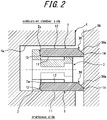
- a side rail 1 forms a multi-piece oil ring (an oil control ring) 3 along with a space expander 2.
- the multi-piece oil ring 3 is a 3-piece type including a pair of side rails 1 provided on both sides of the space expander 2 in the axial direction.
- the multi-piece oil ring 3 is mounted in a ring groove 4a formed in an outer peripheral surface of a piston 4 of a reciprocating internal combustion engine such as a gasoline engine, as illustrated in FIG. 2 .
- the multi-piece oil ring 3 may be a two-piece type, which is a combination of only one side rail 1 and the space expander 2.
- the space expander 2 is made of steel and formed in an annular shape that can be elastically deformed radially inward and outward.
- the space expander 2 is mounted in the ring groove 4a of the piston 4 with elastically deformed in a diameter reducing direction, and presses the side rail 1 so as to expand the diameter of the side rail 1 radially outward and axially outward.
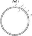
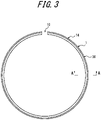
- a pair of side rails 1 have each the same configurations and, as illustrated in FIG. 3 , are each made with a planar steel belt (steel material) that is bent to form a split ring shape with an opening 10. That is, the side rail 1 has a C-shape with the opening 10 formed as a cutout on a circumference of the side rail 1.
- the side rail 1 can be elastically deformed through expansion of the opening 10 in a circumferential direction, thus a diameter of the side rail 1 can be expanded radially outward.
- the side rail 1 includes a first axial side surface 11 facing one side in an axial direction (a downward direction in the figure), a second axial side surface 12 facing the other side in the axial direction (an upward direction in the figure), an inner peripheral surface 13 facing radially inward, and an outer peripheral surface 14 facing radially outward.
- a cross-sectional shape of the side rail 1 perpendicular to its circumferential direction is approximately the same all over the circumference.
- the "axial direction” refers to a direction along an axis center of the side rail 1 formed in a split ring shape.
- the first axial side surface 11 is formed in a flat surface perpendicular to the axial direction. As illustrated in FIG. 2 , the first axial side surface 11 faces a crankcase of an engine in a state where the multi-piece oil ring 3 including the side rail 1 is mounted on the piston 4.
- the second axial side surface 12 is formed in a flat surface perpendicular to the axial direction, i.e., parallel to the first axial side surface 11. As illustrated in FIG. 2 , the second axial side surface 12 faces a combustion chamber of the engine in a state where the multi-piece oil ring 3 including the side rail 1 is mounted on the piston 4.
- an axial distance between the first axial side surface 11 and the second axial side surface 12 of the side rail 1, i.e., an axial thickness (a rail width) W of the side rail 1 is 0.35 mm
- a distance between the inner peripheral surface 13 and the outer peripheral surface 14, i.e., a radial length L of the side rail 1 is 1.52 mm.
- the inner peripheral surface 13 of the side rail 1 is formed in a curved surface (a barrel face) having a vertex at an axial center position. As illustrated in FIG. 2 , the inner peripheral surface 13 of the side rail 1 comes in contact with a mounting plane 2a of the space expander 2 in a state where the multi-piece oil ring 3 including the side rail 1 is mounted on the piston 4.
- the inner peripheral surface 13 is not limited to the above described shape, and may have various shapes including a cylindrical surface parallel to the axial direction, for example.
- the outer peripheral surface 14 of the side rail 1 is formed in a cylindrical surface parallel to the axial direction. As illustrated in FIG. 2 , the outer peripheral surface 14 of the side rail 1 comes in contact with a cylinder inner surface 20.
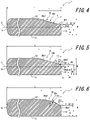
- a beveled portion 30 is provided between the outer peripheral surface 14 and the second axial side surface 12.
- a portion between the outer peripheral surface 14 and the first axial side surface 11 does not need to be beveled but may be formed in a curved surface such as an R shape.
- the R-shape has a radial width and an axial width that are smaller than those of the beveled portion 30.
- the beveled portion 30 includes a tapered surface 30a extending from a starting point toward the second axial side surface 12 while a diameter thereof gradually decreases.
- the starting point is a position located on the outer peripheral surface 14 where a first axial distance B from the first axial side surface 11 toward the second axial side surface is 0.05 mm or more, i.e., a position on the outer peripheral surface 14 that is away from the first axial side surface 11 by 0.05 mm or more toward the second axial side surface 12 in the axial direction.
- the first axial distance B which is the starting point of the beveled portion 30, is more preferably 0.10 mm or more.
- the tapered surface 30a forming the beveled portion 30 includes a first tapered surface portion 30al inclined at an angle ⁇ 1 with respect to the axial direction and a second tapered surface subportion 30a2 provided between the first tapered surface portion 30a1 and the outer peripheral surface 14 and inclined at an angle ⁇ 2, which is smaller than the angle ⁇ 1, with respect to the axial direction.
- the first tapered surface portion 30a1 is continuous to the second axial side surface 12 at an end on the side where the second axial side surface 12 is located.
- the second tapered surface portion 30a2 is continuous to the outer peripheral surface 14 at an end on the side where the first axial side surface 11 is located.
- the anle ⁇ 1 of the first tapered surface portion 30a1 to the axial direction is 10° or more.
- the angle ⁇ 1 of 10° or more allows the beveled portion 30 to be easily distinguished from the portions other than the beveled portion 30, and the visibility of the beveled portion 30 can be ensured.
- the angle ⁇ 1 is preferably 30° or more.
- the difference between the angle ⁇ 1 of the first tapered surface portion 30a1 to the axial direction and the angle ⁇ 2 of the second tapered surface portion 30a2 to the axial direction is preferably 2° or more.
- the difference between the angle ⁇ 1 and the angle ⁇ 2 of 2° or more allows the difference between the reflection angle of the light reflected from the first tapered surface portion 30a1 and the reflection angle of the light reflected from the second tapered surface portion 30a2 to be large, and the visibility of the beveled portion 30 can be enhanced.
- the beveled portion 30 may collide against the cylinder inner surface 20 when the side rail 1 tilts during vertical movement of the piston 4.
- the angle ⁇ 2 of the second tapered surface portion 30a2 to the axial direction is preferably smaller than the angle ⁇ 1 of the first tapered surface portion 30a1 to the axial direction by 2° or more.
- the angle ⁇ 2 of the second tapered surface portion 30a2 to the axial direction is preferably 2° or more and 10° or less.
- the axial distance of the second tapered surface portion 30a2 is preferably 0.10 mm or more, and more preferably 0.15 mm or more.
- both of the first tapered surface portion 30a1 and the second tapered surface portion 30a2 are formed in a shape having a linearly reducing diameter (a conical surface shape), that is, in a linear tapered surface.
- a radial length T of the beveled portion 30, that is, the tapered surface 30a is preferably 0.05 mm or more.
- one of both axial ends of the outer peripheral surface 14 includes the beveled portion 30 having visibility.
- the beveled portion 30 enables, when the side rail 1 has top and bottom (front and back) directionality, workers to easily distinguish the top and bottom of the side rail 1 by viewing the beveled portion 30 with his/her eyes or by using an optical noncontact distinction device during production of the side rail 1 or during assembly of the side rail 1 in the ring groove of the piston. Accordingly, during the work, the side rail 1 can be prevented from being mounted facing a wrong direction.
- the tapered surface 30a forming the beveled portion 30 includes the first tapered surface portion 30a1 and the second tapered surface portion 30a2 that inclines, in the axial direction, with an angle ⁇ 2 that is smaller than that of the first tapered surface portion 30a1, a radial length T of the beveled portion 30 is ensured to enhance its visibility and at the same time, an incident angle to the outer peripheral surface 14 can be reduced by the second tapered surface portion 30a2.
- the beveled portion 30 prevents the edge of the outer peripheral surface 14 from scraping-up the oil to the cylinder inner surface 20, and thus oil consumption can be reduced.
- the angle ⁇ 2 of the second tapered surface portion 30a2 to the axial direction is preferably 2° or more and 12° or less, and more preferably 4° or more and 8° or less.
- a second axial distance C along the axial direction from an axial center position 33 between an end 31 on the side where the first axial side surface 11 of the first tapered surface portion 30a1 is located and an end 32 on the side where the second axial side surface 12 of the second tapered surface portion 30a2 is located to the first axial side surface 11 is preferably 60% or more and 80% or less of the axial thickness W of the side rail 1.
- the second axial distance C is 80% or less of the axial thickness W of the side rail 1
- the radial length T of the beveled portion 30 can be secured to a certain length or more, and thus the visibility of the beveled portion 30 can be enhanced.
- the second axial distance C is 60% or more of the axial thickness W of the side rail 1
- an area of the second tapered surface portion 30a2 can be secured to a certain size or more, and thus oil consumption can be reduced.
- the first tapered surface portion 30a1 is continuous to the second tapered surface portion 30a2, and thus the axial center position 33 is the same position as the end 31 and the end 32.
- the tapered surface 30a forming the beveled portion 30 may be provided with a tapered surface subportion 30a3 in a curved shape between the first tapered surface portion 30a1 and the second tapered surface portion 30a2 so as to smoothly connect the first tapered surface portion 30a1 and the second tapered surface portion 30a2 thereby.
- the tapered surface subportion 30a3 is preferably formed in a curved shape with a certain radius of curvature, it may be formed in a curved shape with a gradually changing radius of curvature. Note that, in the example illustrated in FIG. 5 , as with the example illustrated in FIG. 4 , both of the first tapered surface portion 30a1 and the second tapered surface portion 30a2 are formed in a shape having a linearly reducing diameter (a conical surface shape), that is, in a linear tapered surface.
- the angle ⁇ 1 of the first tapered surface portion 30a1 to the axial direction is 10°or more, and preferably 30° or more. Further, the difference between the angle ⁇ 1 of the first tapered surface portion 30a1 to the axial direction and the angle ⁇ 2 of the second tapered surface portion 30a2 to the axial direction is preferably 2° or more. Further, the angle ⁇ 2 of the second tapered surface portion 30a2 to the axial direction is preferably 2° or more and 12° or less.
- a second axial distance C along the axial direction from the axial center position 33 between the end 31 on the side where the first axial side surface 11 of the first tapered surface portion 30a1 is located and the end 32 on the side where the second axial side surface 12 of the second tapered surface portion 30a2 is located to the first axial side surface 11 is preferably 60% or more and 80% or less of the axial thickness W of the side rail 1. Note that, in the example illustrated in FIG. 5 , the axial center position 33 is located at the axial center of the tapered surface subportion 30a3.
- the first tapered surface portion 30a1 of the beveled portion 30 may be formed also in a curved shape.
- the first tapered surface portion 30a1 is preferably formed in a curved shape with a certain radius of curvature, it may be formed in a curved shape with a gradually changing radius of curvature.
- the second tapered surface portion 30a2 is formed in a shape having a linearly reducing diameter (a conical surface shape), that is, in a linear tapered surface.
- the beveled portion 30 provided with the first tapered surface portion 30a1 in a curved shape enables the beveled portion 30 to be more visible, which further facilitates top and bottom distinction of the side rail 1.
- the angle ⁇ 1 of the first tapered surface portion 30a1 to the axial direction is 10°or more, and preferably 30° or more. Further, the difference between the angle ⁇ 1 of the first tapered surface portion 30a1 to the axial direction and the angle ⁇ 2 of the second tapered surface portion 30a2 to the axial direction is preferably 2° or more. The angle ⁇ 2 of the second tapered surface portion 30a2 to the axial direction is preferably 2° or more and 12° or less.
- a second axial distance C along the axial direction from the axial center position 33 between the end 31 on the side where the first axial side surface 11 of the first tapered surface portion 30a1 is located and the end 32 on the side where the second axial side surface 12 of the second tapered surface portion 30a2 is located to the first axial side surface 11 is preferably 60% or more and 80% or less of the axial thickness W of the side rail 1.
- the angle ⁇ 1 of the first tapered surface portion 30a1 in a curved shape to the axial direction is an angle of a tangent of the first tapered surface portion 30a1 at the end 31 on the side where the first axial side surface 11 of the first tapered surface portion 30al is located to the axial direction.
- tapered surface subportion 30a3 is not provided between the first tapered surface portion 30a1 and the second tapered surface portion 30a2, it may be provided therebetween.
- an outer peripheral surface area A1 in order to facilitate top and bottom distinction of the side rail 1, two areas axially sandwiching the outer peripheral surface area A1, that is, the area A2 of the tapered surface subportion 30a3 and the area A3 of the outer peripheral lower end surface 15 in a curved shape provided between the outer peripheral surface 14 and the first axial side surface 11 are preferably asymmetrical to each other with respect to a virtual plane S passing through the axial center position between the first axial side surface 11 and the second axial side surface 12.
- the outer peripheral surface area A1 of the side rail 1 is preferably formed asymmetric with respect to the axial direction.
- the asymmetric shape may be formed as follows. That is, when a line passing through the axial center thereof and orthogonal to the axial direction is assumed to be a first intermediate line; and at an outer peripheral tip end portion where a contour curve of the outer peripheral surface in the longitudinal cross section is traced, out of two positions on the contour curve corresponding to a position at a distance of 3 ⁇ m from the outer peripheral vertex toward the radial inner peripheral side, a position on the engine combustion chamber side is assumed to be a position a1 and a position on the side away from the engine combustion chamber is assumed to be a position b1, a length of a line segment between the position a1 and the position b1 is assumed to be L1, and an intermediate line of the line segment of the length L1 is assumed to be a second intermediate line; the second intermediate line is located on the side further away from the engine combustion chamber than the
- the outer periphery vertex of the side rail 1 is located on the second intermediate line or on the side further away from the engine combustion chamber than the second intermediate line.
- the contour curve of the outer peripheral surface in the longitudinal cross section is traced from the outer peripheral vertex of the side rail 1 toward radially inner peripheral side by at least 0.025 mm such that a pair of symmetrical shapes exist on the radially inner peripheral side position (both end sides in the axial direction being regarded as a pair).
- the contour curve in an asymmetrical shape at the outer peripheral tip end portion of the side rail 1 is sectioned into a curved portion sandwiched between the outer peripheral vertex and a distance of 1.5 ⁇ m from the outer peripheral vertex toward the radial inner peripheral side and a contour portion sandwiched between a distance of 1.5 ⁇ m and a distance of 3.0 ⁇ m from the outer peripheral vertex toward the radial inner peripheral side, and a first contour section, a second contour section and a third contour section are set from the engine combustion chamber side of the cylinder, the first contour section is provided to be a part of a linear shape or a part of a quadratic curve shape starting from a first end portion on the engine combustion chamber side of the second contour section.
- the second contour section includes the outer peripheral vertex at an intermediate portion thereof and is provided in an arc shape, and the third contour section is provided to be a part of a quadratic curve shape starting from a second end portion on the side away from the engine combustion chamber of the second contour section.
- a surface roughness of the asymmetrical portion of the outer peripheral surface of the side rail 1 is 0.6 ⁇ m Rp or less.
- An asymmetric shape of the outer peripheral surface area A1 of the side rail 1 may also be formed as follows. That is, when a line passing through the center of its segment width is assumed to be a first intermediate line; and at an outer peripheral tip end portion where a contour curve of the outer peripheral surface in the longitudinal cross section is traced, out of two positions on the contour curve corresponding to a position at a distance of 3 ⁇ m from the outer peripheral vertex toward the radial inner peripheral side, a position on the engine combustion chamber side is assumed to be a position a1, a position on the side away from the engine combustion chamber is assumed to be a position b1, a length of a line segment between the position a1 and the position b1 is assumed to be L1, and an intermediate line of the line segment of the length L1 is assumed to be a second intermediate line; the second intermediate line is located on the side further away from the engine combustion chamber than the first intermediate line.
- the outer periphery vertex of the side rail 1 is located on the second intermediate line or on the side further away from the engine combustion chamber than the second intermediate line.
- the contour curve of the outer peripheral surface in the longitudinal cross section is traced from the outer peripheral vertex of the side rail 1 to at least 0.025 mm toward radially inner peripheral side such that a pair of symmetrical shapes exists on the radially inner peripheral side position (both end sides in the axial direction being regarded as a pair).
- the contour curve in an asymmetrical shape at the outer peripheral tip end portion of the side rail 1 is sectioned into a curved portion sandwiched between the outer peripheral vertex and a distance of 1.5 ⁇ m from the outer peripheral vertex toward the radial inner peripheral side and a contour portion sandwiched between a distance of 1.5 ⁇ m and a distance of 3.0 ⁇ m from the outer peripheral vertex toward the inner peripheral side in a segment radial direction, and a first contour section, a second contour section and a third contour section are set from the engine combustion chamber side of the cylinder, the first contour section is provided to be a part of a linear shape or a part of a quadratic curve shape starting from a first end portion on the engine combustion chamber side of the second contour section.
- the second contour section includes a flat portion at an intermediate portion thereof, and is provided to be a part of a linear shape or a part of a quadratic curve shape from an end portion on the engine combustion chamber side of the flat portion in the axial direction then is continuous to the first contour section, further, is provided to be a part of a quadratic curve shape from an end portion on the side away from the engine combustion chamber of the flat portion in the axial direction then is continuous to the third contour section. Further, the third contour section is provided to be a part of a quadratic curve shape continuous to the second end portion.
- a surface roughness of the asymmetrical portion of the outer peripheral surface of the side rail 1 is 0.6 ⁇ m Rp or less.
- a hard film (a hard layer) may be provided at least on the outer peripheral surface 14 and the beveled portion 30, that is, the tapered surface 30a.
- the hard film may contain at least one of a layer treated with nitriding, a PVD-processed layer, a hard-chromium plated layer and a DLC layer.
- PVD treated layer refers to “a layer formed by Physical Vapor Deposition”
- DLC (Diamond Like Carbon) layer refers to a noncrystalline hard carbon film mainly composed of hydrocarbon or carbon allotrope
- the hard film provided on the tapered surface 30a as described above offers effects such as preventing the outer peripheral surface 14 from being deformed due to abrasion, maintaining the outer peripheral shape thereof, less decrease in a surface pressure, maintaining oil controlling functionality, and reducing the oil consumption and fuel consumption of the engine for a long period of time.
- the hard film may provide the beveled portion 30, which is to be viewed by workers, with a hue that is clearly different from a hue of the second axial side surface 12 and the outer peripheral surface 14.
- a difference between the hue of the outer peripheral surface 14 and a hue of the remaining portion becomes more apparent. Therefore, such a hard film as described above may allow the beveled portion 30 to be more easily viewed, further facilitating the top and bottom distinction of the side rail 1.
- One hundred side rails in the shape as illustrated in FIG. 4 were prepared. These side rails each had the axial thickness (W) of 0.35 mm, the first axial distance (B) indicating a beveled position of the beveled portion of 0.15 mm, the angle ( ⁇ 1) of the first tapered surface portion of the beveled portion to the axial direction of 30°, and the angle ( ⁇ 2) of the second tapered surface portion to the axial direction of 6°. Then, top and the bottom distinction was implemented by 10 workers. The workers distinguished the side rail direction with their eyes. As a result, the top and the bottom of all of the side rails were correctly distinguished by the workers.
- a plurality of side rails in the shape as illustrated in FIG. 4 were prepared. These side rails each had an axial thickness (W) of 0.35 mm, a radial length (L) of 1.62 mm, a first axial distance (B) indicating the beveled position of the beveled portion of 0.15 mm, a second axial distance (C) of 67% of the axial thickness (W), that is, 0.23 mm, and an angle ( ⁇ 1) of the first tapered surface portion of the beveled portion to the axial direction of 15°. The angles ( ⁇ 2) of the second tapered surface portions of these side rails to the axial direction were different from each other.
- Distinction of top and bottom directions of these side rails was made by 10 workers.
- the workers could correctly distinguish the directions of all of 100 pieces of side rails when the difference between the angle ( ⁇ 1) of the first tapered surface portion 30a1 to the axial direction and the angle ( ⁇ 2) of the second tapered surface portion 30a2 to the axial direction was 2° or more, and could not correctly distinguish the directions of three of them when the difference was less than 2°. That is, the workers could more correctly distinguish the top and bottom directions of the side rails when the angle ( ⁇ 2) of the second tapered surface portion 30a2 of the side rail to the axial direction wass smaller than the angle ( ⁇ 1) of the first tapered surface portion 30a1 to the axial direction by 2° or more.
- a plurality of multi-piece oil rings were produced with the side rails used in Example 2.
- a plurality of pistons were prepared, each of them having a ring groove in which the produced multi-piece oil ring was mounted, and these pistons were reciprocated in a cylinder for a predetermined number of times and oil consumption was measured.
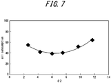
- oil consumption was measured by operating the pistons for a predetermined period of time by using a water-cooled 4-cycle gasoline engine with a supercharger (2 liter, 4 cylinder) under the conditions of 6000 rpm and full load (WOT: Wide Open Throttle).
- WOT Wide Open Throttle
- FIG. 7 is a graph illustrating a relationship between the angle ( ⁇ 2) of the second tapered surface portion 30a2 to the axial direction and the oil consumption in this example.
- the oil consumption was measured by using a side rail having an outer peripheral surface formed in a curved shape (barrel-faced) with a vertex at the axial center position, and the oil consumption measured by using this side rail was regarded as 100.
- FIG. 7 it was found that oil consumption could be reduced when the angle ( ⁇ 2) of the second tapered surface portion to the axial direction was 2° or more and 12° or less, and oil consumption could be further reduced when the angle ( ⁇ 2) was 4° or more and 8° or less.
- the angle ( ⁇ 2) of the second tapered surface portion to the axial direction was 2° or more and 12° or less, no scratches were found on the cylinder inner surface, which indicated possible reduction in collision of the beveled portion against the cylinder inner surface.
- the outer peripheral surface 14 is formed in a cylindrical surface parallel to the axial direction, the outer peripheral surface 14 may be formed into a different shape including a vertically (in front and back sides) asymmetrical shape with a slight shape change.
Landscapes
- Engineering & Computer Science (AREA)
- General Engineering & Computer Science (AREA)
- Mechanical Engineering (AREA)
- Chemical & Material Sciences (AREA)
- Combustion & Propulsion (AREA)
- Pistons, Piston Rings, And Cylinders (AREA)
Applications Claiming Priority (2)
| Application Number | Priority Date | Filing Date | Title |
|---|---|---|---|
| JP2017195287A JP6603284B2 (ja) | 2017-10-05 | 2017-10-05 | サイドレール |
| PCT/JP2018/035483 WO2019069748A1 (ja) | 2017-10-05 | 2018-09-25 | サイドレール |
Publications (3)
| Publication Number | Publication Date |
|---|---|
| EP3677764A1 EP3677764A1 (en) | 2020-07-08 |
| EP3677764A4 EP3677764A4 (en) | 2020-10-28 |
| EP3677764B1 true EP3677764B1 (en) | 2022-11-02 |
Family
ID=65994675
Family Applications (1)
| Application Number | Title | Priority Date | Filing Date |
|---|---|---|---|
| EP18865205.1A Active EP3677764B1 (en) | 2017-10-05 | 2018-09-25 | Side rail |
Country Status (6)
| Country | Link |
|---|---|
| US (1) | US11448317B2 (enExample) |
| EP (1) | EP3677764B1 (enExample) |
| JP (1) | JP6603284B2 (enExample) |
| KR (2) | KR20200080229A (enExample) |
| CN (1) | CN111148893B (enExample) |
| WO (1) | WO2019069748A1 (enExample) |
Families Citing this family (3)
| Publication number | Priority date | Publication date | Assignee | Title |
|---|---|---|---|---|
| CN116897254A (zh) * | 2021-03-31 | 2023-10-17 | 株式会社理研 | 侧轨及具备该侧轨的控油环 |
| JP7224404B1 (ja) | 2021-08-05 | 2023-02-17 | Tpr株式会社 | オイルリング |
| JP7579237B2 (ja) * | 2021-12-28 | 2024-11-07 | 株式会社リケン | ピストンリング及びピストンリングセット |
Citations (3)
| Publication number | Priority date | Publication date | Assignee | Title |
|---|---|---|---|---|
| US7354045B2 (en) * | 2002-10-29 | 2008-04-08 | Toyota Jidosha Kabushiki Kaisha | Oil ring |
| CN203962189U (zh) * | 2013-11-19 | 2014-11-26 | 浙江吉利汽车研究院有限公司 | 一种汽车发动机活塞的油环 |
| JP2017187125A (ja) * | 2016-04-06 | 2017-10-12 | 株式会社リケン | サイドレール |
Family Cites Families (27)
| Publication number | Priority date | Publication date | Assignee | Title |
|---|---|---|---|---|
| US2905512A (en) * | 1958-04-24 | 1959-09-22 | Ramsey Corp | Coated piston ring |
| FR2436160A1 (fr) | 1978-09-13 | 1980-04-11 | Cib | Composition bitumineuse contenant des polymeres et ses applications |
| JPS5763951U (enExample) * | 1980-10-03 | 1982-04-16 | ||
| US4497497A (en) * | 1984-06-21 | 1985-02-05 | Allis-Chalmers Corp. | Oil ring assembly with annular expander spring |
| JPH04117956U (ja) * | 1991-04-04 | 1992-10-22 | 帝国ピストンリング株式会社 | 組合せオイルリング |
| JPH051062U (ja) * | 1991-06-21 | 1993-01-08 | 日野自動車工業株式会社 | ピストンリングの嵌合部構造 |
| JP2003113940A (ja) * | 2001-08-02 | 2003-04-18 | Riken Corp | スチール製ピストンリング |
| JP2003049705A (ja) * | 2001-08-03 | 2003-02-21 | Nippon Piston Ring Co Ltd | 内燃機関の1本リング構成ピストン |
| JP4132815B2 (ja) | 2001-12-28 | 2008-08-13 | 株式会社リケン | サイドレール及び組合せオイルリング |
| CN100410569C (zh) * | 2002-10-29 | 2008-08-13 | 丰田自动车株式会社 | 油环 |
| JP4322500B2 (ja) * | 2002-12-18 | 2009-09-02 | 帝国ピストンリング株式会社 | 組合せオイルリング |
| US20120205876A1 (en) * | 2009-11-30 | 2012-08-16 | Nippon Piston Ring Co., Ltd. | Piston ring |
| WO2011132679A1 (ja) * | 2010-04-19 | 2011-10-27 | 日本ピストンリング株式会社 | 内燃機関用オイルリング |
| WO2011151927A1 (ja) * | 2010-06-04 | 2011-12-08 | 日本ピストンリング株式会社 | 内燃機関用オイルリング |
| US8640314B2 (en) * | 2010-08-03 | 2014-02-04 | Federal-Mogul Corporation | Piston assembly transportation and installation apparatus and methods of transporting and installing a piston assembly therewith |
| DE102011120145A1 (de) * | 2010-12-24 | 2012-06-28 | Mahle International Gmbh | Kolbenring für einen Kolben eines Verbrennungsmotors und Verfahren zu seiner Herstellung |
| DE112012001018T5 (de) * | 2011-02-28 | 2013-12-05 | Nippon Piston Ring Co., Ltd. | Kolbenring |
| JP5564082B2 (ja) * | 2012-08-09 | 2014-07-30 | 株式会社リケン | テーパフェイス形圧力リング用線材及びテーパフェイス形圧力リング |
| WO2015101938A1 (en) * | 2013-12-30 | 2015-07-09 | Mahle International Gmbh | Oil control ring assembly |
| JP6122901B2 (ja) * | 2014-07-31 | 2017-04-26 | 日本ピストンリング株式会社 | 組合せオイルリング |
| US20160040622A1 (en) * | 2014-08-05 | 2016-02-11 | General Electric Company | Piston assembly for a reciprocating engine |
| US20160040780A1 (en) * | 2014-08-05 | 2016-02-11 | General Electric Company | Piston assembly for a reciprocating engine |
| WO2016038916A1 (ja) * | 2014-09-12 | 2016-03-17 | Tpr株式会社 | 組合せオイルリング |
| CN204082367U (zh) * | 2014-09-24 | 2015-01-07 | 仪征威龙发动机零部件有限公司 | 一种低油耗活塞环油环 |
| JP6530200B2 (ja) * | 2015-02-23 | 2019-06-12 | 株式会社リケン | サイドレール |
| JP6533670B2 (ja) * | 2015-03-12 | 2019-06-19 | 株式会社リケン | サイドレール |
| WO2019008780A1 (ja) * | 2017-07-05 | 2019-01-10 | Tpr株式会社 | 組合せオイルリング |
-
2017
- 2017-10-05 JP JP2017195287A patent/JP6603284B2/ja active Active
-
2018
- 2018-09-25 KR KR1020207009765A patent/KR20200080229A/ko not_active Ceased
- 2018-09-25 EP EP18865205.1A patent/EP3677764B1/en active Active
- 2018-09-25 WO PCT/JP2018/035483 patent/WO2019069748A1/ja not_active Ceased
- 2018-09-25 US US16/652,071 patent/US11448317B2/en active Active
- 2018-09-25 CN CN201880063554.2A patent/CN111148893B/zh active Active
- 2018-09-25 KR KR1020227012712A patent/KR20220053049A/ko not_active Ceased
Patent Citations (3)
| Publication number | Priority date | Publication date | Assignee | Title |
|---|---|---|---|---|
| US7354045B2 (en) * | 2002-10-29 | 2008-04-08 | Toyota Jidosha Kabushiki Kaisha | Oil ring |
| CN203962189U (zh) * | 2013-11-19 | 2014-11-26 | 浙江吉利汽车研究院有限公司 | 一种汽车发动机活塞的油环 |
| JP2017187125A (ja) * | 2016-04-06 | 2017-10-12 | 株式会社リケン | サイドレール |
Also Published As
| Publication number | Publication date |
|---|---|
| EP3677764A1 (en) | 2020-07-08 |
| WO2019069748A1 (ja) | 2019-04-11 |
| JP2019065830A (ja) | 2019-04-25 |
| CN111148893B (zh) | 2022-08-30 |
| US20200248808A1 (en) | 2020-08-06 |
| CN111148893A (zh) | 2020-05-12 |
| JP6603284B2 (ja) | 2019-11-06 |
| US11448317B2 (en) | 2022-09-20 |
| KR20200080229A (ko) | 2020-07-06 |
| KR20220053049A (ko) | 2022-04-28 |
| EP3677764A4 (en) | 2020-10-28 |
Similar Documents
| Publication | Publication Date | Title |
|---|---|---|
| EP3270012B1 (en) | Side rail | |
| EP3279524B1 (en) | Side rail | |
| EP3677764B1 (en) | Side rail | |
| JP7254836B2 (ja) | 組合せオイルリング | |
| EP3043054B1 (en) | Cuff-ring for a cylinder liner | |
| US20170227126A1 (en) | Combined oil ring | |
| EP3321543B2 (en) | Internal combustion engine piston ring | |
| US12092222B2 (en) | Piston ring combination, and internal combustion engine | |
| EP4206498B1 (en) | Combination of piston rings and combined structure of piston and piston rings | |
| CN107002872A (zh) | 油环 | |
| JP6762657B2 (ja) | サイドレール | |
| US12292118B2 (en) | Piston ring | |
| US11313467B1 (en) | Piston ring seals | |
| JP6467222B2 (ja) | 組合せオイルリング | |
| JP6659892B2 (ja) | サイドレール | |
| EP4650587A1 (en) | Sliding mechanism | |
| JP2019120403A (ja) | ピストンリング |
Legal Events
| Date | Code | Title | Description |
|---|---|---|---|
| STAA | Information on the status of an ep patent application or granted ep patent |
Free format text: STATUS: THE INTERNATIONAL PUBLICATION HAS BEEN MADE |
|
| PUAI | Public reference made under article 153(3) epc to a published international application that has entered the european phase |
Free format text: ORIGINAL CODE: 0009012 |
|
| STAA | Information on the status of an ep patent application or granted ep patent |
Free format text: STATUS: REQUEST FOR EXAMINATION WAS MADE |
|
| 17P | Request for examination filed |
Effective date: 20200402 |
|
| AK | Designated contracting states |
Kind code of ref document: A1 Designated state(s): AL AT BE BG CH CY CZ DE DK EE ES FI FR GB GR HR HU IE IS IT LI LT LU LV MC MK MT NL NO PL PT RO RS SE SI SK SM TR |
|
| AX | Request for extension of the european patent |
Extension state: BA ME |
|
| A4 | Supplementary search report drawn up and despatched |
Effective date: 20200930 |
|
| RIC1 | Information provided on ipc code assigned before grant |
Ipc: F16J 9/20 20060101ALI20200924BHEP Ipc: F16J 9/06 20060101ALI20200924BHEP Ipc: F02F 5/00 20060101AFI20200924BHEP |
|
| DAV | Request for validation of the european patent (deleted) | ||
| DAX | Request for extension of the european patent (deleted) | ||
| STAA | Information on the status of an ep patent application or granted ep patent |
Free format text: STATUS: EXAMINATION IS IN PROGRESS |
|
| 17Q | First examination report despatched |
Effective date: 20210705 |
|
| GRAP | Despatch of communication of intention to grant a patent |
Free format text: ORIGINAL CODE: EPIDOSNIGR1 |
|
| STAA | Information on the status of an ep patent application or granted ep patent |
Free format text: STATUS: GRANT OF PATENT IS INTENDED |
|
| INTG | Intention to grant announced |
Effective date: 20220704 |
|
| GRAS | Grant fee paid |
Free format text: ORIGINAL CODE: EPIDOSNIGR3 |
|
| GRAA | (expected) grant |
Free format text: ORIGINAL CODE: 0009210 |
|
| STAA | Information on the status of an ep patent application or granted ep patent |
Free format text: STATUS: THE PATENT HAS BEEN GRANTED |
|
| AK | Designated contracting states |
Kind code of ref document: B1 Designated state(s): AL AT BE BG CH CY CZ DE DK EE ES FI FR GB GR HR HU IE IS IT LI LT LU LV MC MK MT NL NO PL PT RO RS SE SI SK SM TR |
|
| REG | Reference to a national code |
Ref country code: GB Ref legal event code: FG4D |
|
| REG | Reference to a national code |
Ref country code: CH Ref legal event code: EP Ref country code: AT Ref legal event code: REF Ref document number: 1528918 Country of ref document: AT Kind code of ref document: T Effective date: 20221115 |
|
| REG | Reference to a national code |
Ref country code: DE Ref legal event code: R096 Ref document number: 602018042702 Country of ref document: DE |
|
| REG | Reference to a national code |
Ref country code: IE Ref legal event code: FG4D |
|
| REG | Reference to a national code |
Ref country code: LT Ref legal event code: MG9D |
|
| REG | Reference to a national code |
Ref country code: NL Ref legal event code: MP Effective date: 20221102 |
|
| REG | Reference to a national code |
Ref country code: AT Ref legal event code: MK05 Ref document number: 1528918 Country of ref document: AT Kind code of ref document: T Effective date: 20221102 |
|
| PG25 | Lapsed in a contracting state [announced via postgrant information from national office to epo] |
Ref country code: SE Free format text: LAPSE BECAUSE OF FAILURE TO SUBMIT A TRANSLATION OF THE DESCRIPTION OR TO PAY THE FEE WITHIN THE PRESCRIBED TIME-LIMIT Effective date: 20221102 Ref country code: PT Free format text: LAPSE BECAUSE OF FAILURE TO SUBMIT A TRANSLATION OF THE DESCRIPTION OR TO PAY THE FEE WITHIN THE PRESCRIBED TIME-LIMIT Effective date: 20230302 Ref country code: NO Free format text: LAPSE BECAUSE OF FAILURE TO SUBMIT A TRANSLATION OF THE DESCRIPTION OR TO PAY THE FEE WITHIN THE PRESCRIBED TIME-LIMIT Effective date: 20230202 Ref country code: LT Free format text: LAPSE BECAUSE OF FAILURE TO SUBMIT A TRANSLATION OF THE DESCRIPTION OR TO PAY THE FEE WITHIN THE PRESCRIBED TIME-LIMIT Effective date: 20221102 Ref country code: FI Free format text: LAPSE BECAUSE OF FAILURE TO SUBMIT A TRANSLATION OF THE DESCRIPTION OR TO PAY THE FEE WITHIN THE PRESCRIBED TIME-LIMIT Effective date: 20221102 Ref country code: ES Free format text: LAPSE BECAUSE OF FAILURE TO SUBMIT A TRANSLATION OF THE DESCRIPTION OR TO PAY THE FEE WITHIN THE PRESCRIBED TIME-LIMIT Effective date: 20221102 Ref country code: AT Free format text: LAPSE BECAUSE OF FAILURE TO SUBMIT A TRANSLATION OF THE DESCRIPTION OR TO PAY THE FEE WITHIN THE PRESCRIBED TIME-LIMIT Effective date: 20221102 |
|
| PG25 | Lapsed in a contracting state [announced via postgrant information from national office to epo] |
Ref country code: RS Free format text: LAPSE BECAUSE OF FAILURE TO SUBMIT A TRANSLATION OF THE DESCRIPTION OR TO PAY THE FEE WITHIN THE PRESCRIBED TIME-LIMIT Effective date: 20221102 Ref country code: PL Free format text: LAPSE BECAUSE OF FAILURE TO SUBMIT A TRANSLATION OF THE DESCRIPTION OR TO PAY THE FEE WITHIN THE PRESCRIBED TIME-LIMIT Effective date: 20221102 Ref country code: LV Free format text: LAPSE BECAUSE OF FAILURE TO SUBMIT A TRANSLATION OF THE DESCRIPTION OR TO PAY THE FEE WITHIN THE PRESCRIBED TIME-LIMIT Effective date: 20221102 Ref country code: IS Free format text: LAPSE BECAUSE OF FAILURE TO SUBMIT A TRANSLATION OF THE DESCRIPTION OR TO PAY THE FEE WITHIN THE PRESCRIBED TIME-LIMIT Effective date: 20230302 Ref country code: HR Free format text: LAPSE BECAUSE OF FAILURE TO SUBMIT A TRANSLATION OF THE DESCRIPTION OR TO PAY THE FEE WITHIN THE PRESCRIBED TIME-LIMIT Effective date: 20221102 Ref country code: GR Free format text: LAPSE BECAUSE OF FAILURE TO SUBMIT A TRANSLATION OF THE DESCRIPTION OR TO PAY THE FEE WITHIN THE PRESCRIBED TIME-LIMIT Effective date: 20230203 |
|
| PG25 | Lapsed in a contracting state [announced via postgrant information from national office to epo] |
Ref country code: NL Free format text: LAPSE BECAUSE OF FAILURE TO SUBMIT A TRANSLATION OF THE DESCRIPTION OR TO PAY THE FEE WITHIN THE PRESCRIBED TIME-LIMIT Effective date: 20221102 |
|
| PG25 | Lapsed in a contracting state [announced via postgrant information from national office to epo] |
Ref country code: SM Free format text: LAPSE BECAUSE OF FAILURE TO SUBMIT A TRANSLATION OF THE DESCRIPTION OR TO PAY THE FEE WITHIN THE PRESCRIBED TIME-LIMIT Effective date: 20221102 Ref country code: RO Free format text: LAPSE BECAUSE OF FAILURE TO SUBMIT A TRANSLATION OF THE DESCRIPTION OR TO PAY THE FEE WITHIN THE PRESCRIBED TIME-LIMIT Effective date: 20221102 Ref country code: EE Free format text: LAPSE BECAUSE OF FAILURE TO SUBMIT A TRANSLATION OF THE DESCRIPTION OR TO PAY THE FEE WITHIN THE PRESCRIBED TIME-LIMIT Effective date: 20221102 Ref country code: DK Free format text: LAPSE BECAUSE OF FAILURE TO SUBMIT A TRANSLATION OF THE DESCRIPTION OR TO PAY THE FEE WITHIN THE PRESCRIBED TIME-LIMIT Effective date: 20221102 Ref country code: CZ Free format text: LAPSE BECAUSE OF FAILURE TO SUBMIT A TRANSLATION OF THE DESCRIPTION OR TO PAY THE FEE WITHIN THE PRESCRIBED TIME-LIMIT Effective date: 20221102 |
|
| REG | Reference to a national code |
Ref country code: DE Ref legal event code: R097 Ref document number: 602018042702 Country of ref document: DE |
|
| PG25 | Lapsed in a contracting state [announced via postgrant information from national office to epo] |
Ref country code: SK Free format text: LAPSE BECAUSE OF FAILURE TO SUBMIT A TRANSLATION OF THE DESCRIPTION OR TO PAY THE FEE WITHIN THE PRESCRIBED TIME-LIMIT Effective date: 20221102 Ref country code: AL Free format text: LAPSE BECAUSE OF FAILURE TO SUBMIT A TRANSLATION OF THE DESCRIPTION OR TO PAY THE FEE WITHIN THE PRESCRIBED TIME-LIMIT Effective date: 20221102 |
|
| PLBE | No opposition filed within time limit |
Free format text: ORIGINAL CODE: 0009261 |
|
| STAA | Information on the status of an ep patent application or granted ep patent |
Free format text: STATUS: NO OPPOSITION FILED WITHIN TIME LIMIT |
|
| 26N | No opposition filed |
Effective date: 20230803 |
|
| PG25 | Lapsed in a contracting state [announced via postgrant information from national office to epo] |
Ref country code: SI Free format text: LAPSE BECAUSE OF FAILURE TO SUBMIT A TRANSLATION OF THE DESCRIPTION OR TO PAY THE FEE WITHIN THE PRESCRIBED TIME-LIMIT Effective date: 20221102 |
|
| REG | Reference to a national code |
Ref country code: CH Ref legal event code: PL |
|
| PG25 | Lapsed in a contracting state [announced via postgrant information from national office to epo] |
Ref country code: LU Free format text: LAPSE BECAUSE OF NON-PAYMENT OF DUE FEES Effective date: 20230925 |
|
| REG | Reference to a national code |
Ref country code: BE Ref legal event code: MM Effective date: 20230930 |
|
| PG25 | Lapsed in a contracting state [announced via postgrant information from national office to epo] |
Ref country code: MC Free format text: LAPSE BECAUSE OF FAILURE TO SUBMIT A TRANSLATION OF THE DESCRIPTION OR TO PAY THE FEE WITHIN THE PRESCRIBED TIME-LIMIT Effective date: 20221102 Ref country code: LU Free format text: LAPSE BECAUSE OF NON-PAYMENT OF DUE FEES Effective date: 20230925 Ref country code: IT Free format text: LAPSE BECAUSE OF FAILURE TO SUBMIT A TRANSLATION OF THE DESCRIPTION OR TO PAY THE FEE WITHIN THE PRESCRIBED TIME-LIMIT Effective date: 20221102 |
|
| REG | Reference to a national code |
Ref country code: IE Ref legal event code: MM4A |
|
| PG25 | Lapsed in a contracting state [announced via postgrant information from national office to epo] |
Ref country code: IE Free format text: LAPSE BECAUSE OF NON-PAYMENT OF DUE FEES Effective date: 20230925 |
|
| PG25 | Lapsed in a contracting state [announced via postgrant information from national office to epo] |
Ref country code: CH Free format text: LAPSE BECAUSE OF NON-PAYMENT OF DUE FEES Effective date: 20230930 |
|
| PG25 | Lapsed in a contracting state [announced via postgrant information from national office to epo] |
Ref country code: IE Free format text: LAPSE BECAUSE OF NON-PAYMENT OF DUE FEES Effective date: 20230925 Ref country code: CH Free format text: LAPSE BECAUSE OF NON-PAYMENT OF DUE FEES Effective date: 20230930 |
|
| PG25 | Lapsed in a contracting state [announced via postgrant information from national office to epo] |
Ref country code: BE Free format text: LAPSE BECAUSE OF NON-PAYMENT OF DUE FEES Effective date: 20230930 |
|
| PG25 | Lapsed in a contracting state [announced via postgrant information from national office to epo] |
Ref country code: BG Free format text: LAPSE BECAUSE OF FAILURE TO SUBMIT A TRANSLATION OF THE DESCRIPTION OR TO PAY THE FEE WITHIN THE PRESCRIBED TIME-LIMIT Effective date: 20221102 |
|
| PG25 | Lapsed in a contracting state [announced via postgrant information from national office to epo] |
Ref country code: BG Free format text: LAPSE BECAUSE OF FAILURE TO SUBMIT A TRANSLATION OF THE DESCRIPTION OR TO PAY THE FEE WITHIN THE PRESCRIBED TIME-LIMIT Effective date: 20221102 |
|
| PG25 | Lapsed in a contracting state [announced via postgrant information from national office to epo] |
Ref country code: CY Free format text: LAPSE BECAUSE OF FAILURE TO SUBMIT A TRANSLATION OF THE DESCRIPTION OR TO PAY THE FEE WITHIN THE PRESCRIBED TIME-LIMIT; INVALID AB INITIO Effective date: 20180925 |
|
| PG25 | Lapsed in a contracting state [announced via postgrant information from national office to epo] |
Ref country code: HU Free format text: LAPSE BECAUSE OF FAILURE TO SUBMIT A TRANSLATION OF THE DESCRIPTION OR TO PAY THE FEE WITHIN THE PRESCRIBED TIME-LIMIT; INVALID AB INITIO Effective date: 20180925 |
|
| PGFP | Annual fee paid to national office [announced via postgrant information from national office to epo] |
Ref country code: DE Payment date: 20250730 Year of fee payment: 8 |
|
| PGFP | Annual fee paid to national office [announced via postgrant information from national office to epo] |
Ref country code: GB Payment date: 20250807 Year of fee payment: 8 |
|
| PGFP | Annual fee paid to national office [announced via postgrant information from national office to epo] |
Ref country code: FR Payment date: 20250808 Year of fee payment: 8 |
|
| PG25 | Lapsed in a contracting state [announced via postgrant information from national office to epo] |
Ref country code: TR Free format text: LAPSE BECAUSE OF FAILURE TO SUBMIT A TRANSLATION OF THE DESCRIPTION OR TO PAY THE FEE WITHIN THE PRESCRIBED TIME-LIMIT Effective date: 20221102 |