WO2019065885A1 - Dispositif de réglage de composition d'air - Google Patents
Dispositif de réglage de composition d'air Download PDFInfo
- Publication number
- WO2019065885A1 WO2019065885A1 PCT/JP2018/036050 JP2018036050W WO2019065885A1 WO 2019065885 A1 WO2019065885 A1 WO 2019065885A1 JP 2018036050 W JP2018036050 W JP 2018036050W WO 2019065885 A1 WO2019065885 A1 WO 2019065885A1
- Authority
- WO
- WIPO (PCT)
- Prior art keywords
- air
- carbon dioxide
- concentration
- oxygen concentration
- oxygen
- Prior art date
Links
Images


Classifications
-
- A—HUMAN NECESSITIES
- A23—FOODS OR FOODSTUFFS; TREATMENT THEREOF, NOT COVERED BY OTHER CLASSES
- A23L—FOODS, FOODSTUFFS, OR NON-ALCOHOLIC BEVERAGES, NOT COVERED BY SUBCLASSES A21D OR A23B-A23J; THEIR PREPARATION OR TREATMENT, e.g. COOKING, MODIFICATION OF NUTRITIVE QUALITIES, PHYSICAL TREATMENT; PRESERVATION OF FOODS OR FOODSTUFFS, IN GENERAL
- A23L3/00—Preservation of foods or foodstuffs, in general, e.g. pasteurising, sterilising, specially adapted for foods or foodstuffs
- A23L3/34—Preservation of foods or foodstuffs, in general, e.g. pasteurising, sterilising, specially adapted for foods or foodstuffs by treatment with chemicals
- A23L3/3409—Preservation of foods or foodstuffs, in general, e.g. pasteurising, sterilising, specially adapted for foods or foodstuffs by treatment with chemicals in the form of gases, e.g. fumigation; Compositions or apparatus therefor
- A23L3/34095—Details of apparatus for generating or regenerating gases
-
- F—MECHANICAL ENGINEERING; LIGHTING; HEATING; WEAPONS; BLASTING
- F24—HEATING; RANGES; VENTILATING
- F24F—AIR-CONDITIONING; AIR-HUMIDIFICATION; VENTILATION; USE OF AIR CURRENTS FOR SCREENING
- F24F7/00—Ventilation
- F24F7/04—Ventilation with ducting systems, e.g. by double walls; with natural circulation
- F24F7/06—Ventilation with ducting systems, e.g. by double walls; with natural circulation with forced air circulation, e.g. by fan positioning of a ventilator in or against a conduit
-
- A—HUMAN NECESSITIES
- A23—FOODS OR FOODSTUFFS; TREATMENT THEREOF, NOT COVERED BY OTHER CLASSES
- A23B—PRESERVING, e.g. BY CANNING, MEAT, FISH, EGGS, FRUIT, VEGETABLES, EDIBLE SEEDS; CHEMICAL RIPENING OF FRUIT OR VEGETABLES; THE PRESERVED, RIPENED, OR CANNED PRODUCTS
- A23B7/00—Preservation or chemical ripening of fruit or vegetables
- A23B7/14—Preserving or ripening with chemicals not covered by groups A23B7/08 or A23B7/10
- A23B7/144—Preserving or ripening with chemicals not covered by groups A23B7/08 or A23B7/10 in the form of gases, e.g. fumigation; Compositions or apparatus therefor
- A23B7/148—Preserving or ripening with chemicals not covered by groups A23B7/08 or A23B7/10 in the form of gases, e.g. fumigation; Compositions or apparatus therefor in a controlled atmosphere, e.g. partial vacuum, comprising only CO2, N2, O2 or H2O
-
- A—HUMAN NECESSITIES
- A23—FOODS OR FOODSTUFFS; TREATMENT THEREOF, NOT COVERED BY OTHER CLASSES
- A23L—FOODS, FOODSTUFFS, OR NON-ALCOHOLIC BEVERAGES, NOT COVERED BY SUBCLASSES A21D OR A23B-A23J; THEIR PREPARATION OR TREATMENT, e.g. COOKING, MODIFICATION OF NUTRITIVE QUALITIES, PHYSICAL TREATMENT; PRESERVATION OF FOODS OR FOODSTUFFS, IN GENERAL
- A23L3/00—Preservation of foods or foodstuffs, in general, e.g. pasteurising, sterilising, specially adapted for foods or foodstuffs
- A23L3/34—Preservation of foods or foodstuffs, in general, e.g. pasteurising, sterilising, specially adapted for foods or foodstuffs by treatment with chemicals
- A23L3/3409—Preservation of foods or foodstuffs, in general, e.g. pasteurising, sterilising, specially adapted for foods or foodstuffs by treatment with chemicals in the form of gases, e.g. fumigation; Compositions or apparatus therefor
- A23L3/3418—Preservation of foods or foodstuffs, in general, e.g. pasteurising, sterilising, specially adapted for foods or foodstuffs by treatment with chemicals in the form of gases, e.g. fumigation; Compositions or apparatus therefor in a controlled atmosphere, e.g. partial vacuum, comprising only CO2, N2, O2 or H2O
-
- B—PERFORMING OPERATIONS; TRANSPORTING
- B01—PHYSICAL OR CHEMICAL PROCESSES OR APPARATUS IN GENERAL
- B01D—SEPARATION
- B01D53/00—Separation of gases or vapours; Recovering vapours of volatile solvents from gases; Chemical or biological purification of waste gases, e.g. engine exhaust gases, smoke, fumes, flue gases, aerosols
- B01D53/02—Separation of gases or vapours; Recovering vapours of volatile solvents from gases; Chemical or biological purification of waste gases, e.g. engine exhaust gases, smoke, fumes, flue gases, aerosols by adsorption, e.g. preparative gas chromatography
- B01D53/04—Separation of gases or vapours; Recovering vapours of volatile solvents from gases; Chemical or biological purification of waste gases, e.g. engine exhaust gases, smoke, fumes, flue gases, aerosols by adsorption, e.g. preparative gas chromatography with stationary adsorbents
- B01D53/0407—Constructional details of adsorbing systems
- B01D53/0446—Means for feeding or distributing gases
-
- B—PERFORMING OPERATIONS; TRANSPORTING
- B01—PHYSICAL OR CHEMICAL PROCESSES OR APPARATUS IN GENERAL
- B01D—SEPARATION
- B01D53/00—Separation of gases or vapours; Recovering vapours of volatile solvents from gases; Chemical or biological purification of waste gases, e.g. engine exhaust gases, smoke, fumes, flue gases, aerosols
- B01D53/02—Separation of gases or vapours; Recovering vapours of volatile solvents from gases; Chemical or biological purification of waste gases, e.g. engine exhaust gases, smoke, fumes, flue gases, aerosols by adsorption, e.g. preparative gas chromatography
- B01D53/04—Separation of gases or vapours; Recovering vapours of volatile solvents from gases; Chemical or biological purification of waste gases, e.g. engine exhaust gases, smoke, fumes, flue gases, aerosols by adsorption, e.g. preparative gas chromatography with stationary adsorbents
- B01D53/0454—Controlling adsorption
-
- B—PERFORMING OPERATIONS; TRANSPORTING
- B01—PHYSICAL OR CHEMICAL PROCESSES OR APPARATUS IN GENERAL
- B01D—SEPARATION
- B01D53/00—Separation of gases or vapours; Recovering vapours of volatile solvents from gases; Chemical or biological purification of waste gases, e.g. engine exhaust gases, smoke, fumes, flue gases, aerosols
- B01D53/22—Separation of gases or vapours; Recovering vapours of volatile solvents from gases; Chemical or biological purification of waste gases, e.g. engine exhaust gases, smoke, fumes, flue gases, aerosols by diffusion
- B01D53/229—Integrated processes (Diffusion and at least one other process, e.g. adsorption, absorption)
-
- B—PERFORMING OPERATIONS; TRANSPORTING
- B01—PHYSICAL OR CHEMICAL PROCESSES OR APPARATUS IN GENERAL
- B01D—SEPARATION
- B01D2256/00—Main component in the product gas stream after treatment
- B01D2256/12—Oxygen
-
- B—PERFORMING OPERATIONS; TRANSPORTING
- B01—PHYSICAL OR CHEMICAL PROCESSES OR APPARATUS IN GENERAL
- B01D—SEPARATION
- B01D2256/00—Main component in the product gas stream after treatment
- B01D2256/22—Carbon dioxide
-
- B—PERFORMING OPERATIONS; TRANSPORTING
- B01—PHYSICAL OR CHEMICAL PROCESSES OR APPARATUS IN GENERAL
- B01D—SEPARATION
- B01D2257/00—Components to be removed
- B01D2257/10—Single element gases other than halogens
- B01D2257/104—Oxygen
-
- B—PERFORMING OPERATIONS; TRANSPORTING
- B01—PHYSICAL OR CHEMICAL PROCESSES OR APPARATUS IN GENERAL
- B01D—SEPARATION
- B01D2257/00—Components to be removed
- B01D2257/50—Carbon oxides
- B01D2257/504—Carbon dioxide
-
- B—PERFORMING OPERATIONS; TRANSPORTING
- B01—PHYSICAL OR CHEMICAL PROCESSES OR APPARATUS IN GENERAL
- B01D—SEPARATION
- B01D2259/00—Type of treatment
- B01D2259/45—Gas separation or purification devices adapted for specific applications
- B01D2259/4525—Gas separation or purification devices adapted for specific applications for storage and dispensing systems
-
- Y—GENERAL TAGGING OF NEW TECHNOLOGICAL DEVELOPMENTS; GENERAL TAGGING OF CROSS-SECTIONAL TECHNOLOGIES SPANNING OVER SEVERAL SECTIONS OF THE IPC; TECHNICAL SUBJECTS COVERED BY FORMER USPC CROSS-REFERENCE ART COLLECTIONS [XRACs] AND DIGESTS
- Y02—TECHNOLOGIES OR APPLICATIONS FOR MITIGATION OR ADAPTATION AGAINST CLIMATE CHANGE
- Y02C—CAPTURE, STORAGE, SEQUESTRATION OR DISPOSAL OF GREENHOUSE GASES [GHG]
- Y02C20/00—Capture or disposal of greenhouse gases
- Y02C20/40—Capture or disposal of greenhouse gases of CO2
Definitions
- the present disclosure relates to an air composition regulator.
- the composition for example, the oxygen concentration and carbon dioxide concentration of the air in the storage
- In-room air conditioners are known to adjust.
- Patent Document 1 discloses a container having an apparatus for adjusting the composition of air in a storage.
- the apparatus of Patent Document 1 uses a gas separation membrane to adjust the composition of the air in the storage.
- the inside air In containers with this type of equipment, in order to keep the freshness of plants such as agricultural products for a long period of time, the inside air generally has an oxygen concentration (eg 5 to 8%) lower than the oxygen concentration of the atmosphere (about 21%). Maintained, the carbon dioxide concentration is maintained at a higher concentration than in the atmosphere.
- the carbon dioxide is selectively removed from the air by ventilating or dissolving the carbon dioxide in a liquid using a scrubber.
- ventilation is generally performed to introduce fresh air into the storage.
- An object of the present disclosure is to enable the oxygen concentration of air in a target space whose composition is adjusted by the air composition adjustment device to be higher than the oxygen concentration in the atmosphere.
- a first aspect of the present disclosure is an air composition adjusting device that adjusts the composition of air in a target space (5), An oxygen separation unit (41, 61) for separating oxygen from the outside air supplied to the target space (5); A gas supply path (135) including an oxygen high concentration gas supply path (136) communicating with the target space (5) from the oxygen separation unit (41, 61); Oxygen concentration to supply high oxygen concentration gas having oxygen concentration higher than the outside air before treatment in the oxygen separation unit (41, 61) to the target space (5) through the high concentration gas supply path (136) for oxygen A controller (110) for raising operation; It is characterized by having.
- a high oxygen concentration gas is generated by the air before treatment passing through the oxygen separation section (41, 61), and this high oxygen concentration gas passes through the high concentration gas supply path (136) for oxygen. Is supplied to the target space (5). Therefore, the oxygen concentration of the air in the target space (5) whose composition is adjusted by the air composition adjustment device can be made higher than the oxygen concentration in the atmosphere.
- the oxygen separation unit (41, 61) is configured to separate the outside air into the high oxygen concentration gas and a low oxygen concentration gas whose oxygen concentration is lower than that before treatment.
- the gas supply path (135) selectively supplies one of the high oxygen concentration gas and the low oxygen concentration gas, and the low concentration gas supply path (137) for low oxygen concentration gas to the target space (5).
- the controller (110) is characterized in that the switch (56, 58) is switched to supply the high oxygen concentration gas or the low oxygen concentration gas to the target space (5). .
- the high oxygen concentration gas or the low oxygen concentration gas can be selectively supplied to the target space (5) by switching the switch (56, 58).
- the oxygen separation unit (41, 61) is characterized by including a separation membrane (85) for separating oxygen from the open air.
- the oxygen concentration of the air in the target space (5) can be made higher than the oxygen concentration in the atmosphere.
- a fourth aspect of the present disclosure relates to any one of the first to third aspects: Furthermore, the carbon dioxide separation unit (41, 61) for separating carbon dioxide from the air to be treated supplied to the target space (5), and the communication from the carbon dioxide separation unit (41, 61) to the target space (5) And a high concentration gas supply path (136) for carbon dioxide,
- the controller (110) in addition to the oxygen concentration increasing operation, further includes a high carbon dioxide concentration gas having a carbon dioxide concentration higher than that of the air to be treated before the treatment in the carbon dioxide separation unit (41, 61). It is characterized in that it is configured to be able to perform a carbon dioxide concentration raising operation to be supplied to the target space (5) through the high concentration gas supply path (136) for carbon dioxide.
- a high carbon dioxide concentration gas is generated by passing air before treatment through the carbon dioxide separation unit (41, 61), and the high carbon dioxide concentration gas is supplied to the high concentration gas supply path for carbon dioxide ( It is supplied to the target space (5) through 136). Therefore, the carbon dioxide concentration of the air in the target space (5) whose composition is adjusted by the air composition adjusting device can be made higher than the carbon dioxide concentration before the treatment.
- the carbon dioxide separation unit (41, 61) is configured to separate the process air into the high carbon dioxide gas and the low carbon dioxide gas having a lower carbon dioxide concentration than that before the treatment.
- the gas supply path (135) is a carbon dioxide low concentration gas supply path (137) for supplying a low carbon dioxide concentration gas to the target space (5), and one of a high carbon dioxide concentration gas and a low carbon dioxide concentration gas
- a switch (76, 78) for selectively supplying the target space (5)
- the controller (110) is characterized in that the switch (76, 78) is switched to supply the high carbon dioxide gas or the low carbon dioxide gas to the target space (5).
- the high carbon dioxide gas or the low carbon dioxide gas can be selectively supplied to the target space (5) by switching the switch (76, 78).
- nitrogen, oxygen and carbon dioxide are separated from the air in the storage space of the target space (5), and a low oxygen concentration gas having a higher nitrogen concentration and a lower oxygen concentration and carbon dioxide concentration than the storage air;
- An adsorption unit (234, 235) provided with an adsorbent capable of generating a high oxygen concentration gas having a nitrogen concentration lower than air and a high oxygen concentration and carbon dioxide concentration is characterized.
- the separation membrane (85) can be used to make the oxygen concentration of air in the target space (5) higher than the oxygen concentration in the atmosphere.
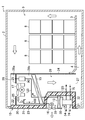
- FIG. 1 is a schematic cross-sectional view of a transportation container provided with an in-compartment air conditioning device of the embodiment.
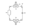
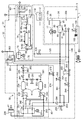
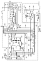
- FIG. 2 is a refrigerant circuit diagram showing the configuration of the refrigerant circuit of the container refrigerator provided in the transport container.
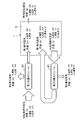
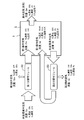
- FIG. 3 is a piping system diagram showing a configuration of the in-compartment air conditioning device of the embodiment.
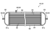
- FIG. 4 is a schematic sectional drawing of the isolation
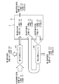
- FIG. 5: is a block diagram which shows the oxygen concentration reduction operation
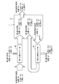
- FIG. 6 is a block diagram showing the carbon dioxide concentration reduction operation performed by the in-compartment air conditioning device of the embodiment.
- FIG. 1 is a schematic cross-sectional view of a transportation container provided with an in-compartment air conditioning device of the embodiment.
- FIG. 2 is a refrigerant circuit diagram showing the configuration of the refrigerant circuit of
- FIG. 7 is a block diagram showing the oxygen concentration recovery operation performed by the in-compartment air conditioning device of the embodiment.
- FIG. 8 is a block diagram showing another example of the oxygen concentration recovery operation performed by the in-compartment air conditioning device of the embodiment.
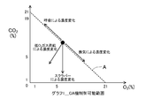
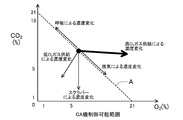
- FIG. 9 is a graph showing changes in oxygen concentration and carbon dioxide concentration in the refrigerator.
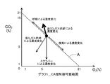
- FIG. 10 is a graph showing changes in oxygen concentration and carbon dioxide concentration in the refrigerator by the oxygen concentration increasing operation of the embodiment.
- FIG. 11 is a graph showing changes in oxygen concentration and carbon dioxide concentration in the refrigerator by the carbon dioxide concentration increasing operation according to the embodiment.
- FIG. 12 is a piping system diagram showing a configuration of the in-compartment air conditioning device of the second embodiment.
- FIG. 13 is a piping diagram of the in-compartment air conditioning device, showing a state in which the first composition regulation unit of the second embodiment is in the first operation.
- FIG. 14 is a piping diagram of the in-compartment air conditioning device, which shows the state during the second operation of the first composition adjusting portion of the second embodiment.
- Embodiment 1 Embodiments will be described in detail based on the drawings.
- the air composition adjusting device of the present embodiment is an in-compartment air adjusting device (30) provided in a transport container (storage) (1) for carrying out so-called CA Controlled Atmosphere transport. Then, the in-compartment air conditioner (30) adjusts the composition of the air in the internal space (target space) of the transport container (1) to be different from the composition of the atmosphere that is the air of the external space, Adjust to return to the composition.
- the transport container (1) constituting the storage has a container body (2) and a container refrigerator (10).
- the transport container (1) is a temperature control or a reefer container capable of being stored in a storage.
- the in-compartment air conditioner (30) of the present embodiment is installed in the container refrigerator (10).
- the transport container (1) is used to transport plants such as agricultural products that take in oxygen (O 2 ) in the air and release carbon dioxide (CO 2 ) as cargo (6). Examples of plants include fruits such as banana and avocado, vegetables, grains, bulbs, fresh flowers and the like.
- the container body (2) is formed in an elongated rectangular parallelepiped box shape.
- the container body (2) is open at one end face, and the container refrigerator (10) is attached so as to close the open end.
- the internal space of the container body (2) constitutes a loading space (5) for storing the cargo (6).
- a floor plate (3) for placing the cargo (6) is arranged.
- an underfloor flow path (4) for flowing air blown out by the container refrigerator (10) is formed between the floor plate (3) and the bottom plate of the container body (2).
- the underfloor channel (4) is a channel extending in the longitudinal direction of the container body (2) along the bottom plate of the container body (2).
- one end is connected to the outlet (27) of the container refrigerator (10), and the other end is a space above the floor plate (3) (ie, a space in which the cargo (6) is accommodated) It communicates with).
- the container refrigerator (10) includes a casing (20), a refrigerant circuit (11) performing a refrigeration cycle, an external fan (16), and an internal fan (17). And have.
- the casing (20) includes a storage outer wall (21), a storage inner wall (22), a back plate (24), and a dividing plate (25). As described later, the casing (20) is provided with a refrigerant circuit (11), an external fan (16), and an internal fan (17).
- the storage outer wall portion (21) is a plate-like member disposed so as to cover the open end of the container main body (2).
- the lower portion of the storage outer wall (21) bulges to the inside of the container body (2).
- the storage inner wall portion (22) is a plate-like member having a form along the storage outer wall portion (21).
- the storage inner wall (22) is arranged to cover the inner surface of the container body (2) in the storage outer wall (21).
- a heat insulating material (23) is filled in the space between the storage outer wall (21) and the storage inner wall (22).
- the lower portion of the casing (20) is recessed inward of the container body (2).
- the lower part of the casing (20) forms an external storage compartment (28) in communication with the external space of the transport container (1).
- An extra-compartment fan (16) is disposed in the extra-compartment equipment room (28).
- the back plate (24) is a substantially rectangular flat member.
- the back plate (24) is disposed on the inner side of the container body (2) than the storage inner wall (22), and forms an internal air flow passage (29) with the storage inner wall (22).
- the upper end of the in-compartment air flow passage (29) constitutes the suction port (26) of the casing (20), and the lower end thereof constitutes the blowout port (27) of the casing (20).
- the partition plate (25) is a plate-like member arranged to partition the internal air flow passage (29) up and down.
- the partition plate (25) is disposed in the upper part of the internal air flow passage (29).
- the compartment air passage (29) is provided with the primary flow passage (29a) above the partition plate (25) and the secondary flow passage (29b) below the partition plate (25) by the partition plate (25).
- Divided into The primary flow passage (29a) communicates with the loading space (5) through the suction port (26).
- the secondary flow passage (29b) communicates with the underfloor flow passage (4) through the blowout port (27).
- An internal fan (17) is attached to the partition plate (25).
- the internal fan (17) is arranged to blow out the air drawn from the primary flow passage (29a) to the secondary flow passage (29b).
- the refrigerant circuit (11) is formed by connecting a compressor (12), a condenser (13), an expansion valve (14), and an evaporator (15) by piping. Closed circuit.
- the compressor (12) When the compressor (12) is operated, the refrigerant circulates through the refrigerant circuit (11) to perform a vapor compression refrigeration cycle.
- the condenser (13) is disposed on the suction side of the external fan (16) in the external equipment chamber (28), and the evaporator (15) is an internal air flow path (29) Are arranged in the secondary flow path (29b) of Moreover, although illustration is abbreviate
- the in-compartment air conditioner (30) comprises a main body unit (31), a sensor unit (90), a ventilating exhaust pipe (100), and a controller (110).
- the main unit (31) is installed in the extra-compartment equipment room (28) of the container refrigerator (10).
- the sensor unit (90) is installed in the in-compartment air flow path (29) of the transport container (1).
- the ventilation exhaust pipe (100) is installed across the in-compartment air flow path (29) of the transport container (1) and the out-of-compartment equipment room (28).
- the controller (110) is provided in the main body unit (31) to control constituent devices of the in-compartment air conditioner (30).
- the main body unit (31) of the in-compartment air conditioning device (30) includes a first composition regulation unit (40), a second composition regulation unit (60), and a pump unit (35).
- a unit case (32) is provided.
- the unit case (32) is a box-like closed container.
- the first composition adjusting unit (40), the second composition adjusting unit (60), and the pump unit (35) are disposed in the internal space of the unit case (32).
- each composition control unit (40, 60) The supply air (the air outside the first storage, the second air outside the second storage, the air inside the first storage, the air inside the second storage) which has a different component ratio of oxygen and carbon dioxide from the air in the storage ) Is configured to be able to supply the supply air to the inner space of the transport container (1).
- the in-compartment air conditioning device (30) includes a supply pipe (120), an in-compartment suction pipe (75), and a measurement pipe (125).
- the supply pipe (120), the storage inner suction pipe (75), and the measurement pipe (125) are for connecting the main body unit (31) to the internal air flow path (29) of the container refrigerator (10). It is piping.
- the supply pipe (120) is a pipe for supplying the air flowing out of the first composition control unit (40) and the second composition control unit (60) to the loading space (5).
- the inlet end of the supply pipe (120) is connected to the first composition adjusting unit (40) and the second composition adjusting unit (60), and the outlet end is the secondary flow passage (29b) of the internal air flow passage (29) Open to
- the storage inner suction pipe (75) is a pipe for supplying the storage internal air in the loading space (5) to the second composition adjustment section (60).
- the inlet end of the storage inner suction pipe (75) opens to the secondary flow passage (29b) of the storage inner air flow passage (29), and the outlet end of the second pump of the second composition adjustment unit (60) 37) connected.
- the inlet end of the storage inner suction pipe (75) is disposed upstream of the outlet end of the supply pipe (120).
- the measurement pipe (125) is a pipe for supplying the air flowing through the supply pipe (120) to the sensor unit (90).
- the measurement pipe (125) has an inlet end connected to the supply pipe (120) and an outlet end connected to the sensor unit (90). Further, the measurement pipe (125) is provided with a measurement on-off valve (126) consisting of a solenoid valve.
- the measurement on-off valve (126) is housed in a unit case (32) of the main unit (31).
- the pipes (51 to 55, 57, 59, 71 to 74, 77, 79, 95) may be made of hard pipes, may be made of flexible hoses, or pipes and hoses. It may be configured by combining
- the pump unit (35) includes a first pump (36), a second pump (37), and a drive motor (38).
- Each of the first pump (36) and the second pump (37) is an air pump for discharging the sucked air.
- Each of the first pump (36) and the second pump (37) is constituted by, for example, a positive displacement fluid machine.
- the first pump (36) and the second pump (37) are integrated.
- the drive motor (38) is a motor connected to the first pump (36) and the second pump (37). The drive motor (38) drives both the first pump (36) and the second pump (37).
- the first composition control unit (40) is configured to draw the first outside air (low oxygen concentration gas) and the second outside air (air outside the non-storage room) sucked from the outside of the transport container (1) High oxygen concentration gas).
- the first composition adjustment unit (40) of the present embodiment supplies the first outside air, which is supply air, to the loading space (5) and discharges the second outside air to the outside of the transport container (1).
- the first outside air can be discharged to the outside and the second outside air can be supplied to the loading space (5).
- the first composition control unit (40) is an air filter (47) and a first separation module (first separation unit: an oxygen separation unit that separates oxygen and carbon dioxide from air before treatment, and is a carbon dioxide separation unit (41), a first bypass valve (50), a first pressure sensor (45) and a first control valve (46).
- first composition adjusting unit (40) includes a storage outside suction pipe (55), a first introduction pipe (52), a first primary side pipe (53), and a first secondary side pipe (54). , And a first bypass pipe (51).
- the first pump (36) of the pump unit (35) constitutes this first composition adjustment section (40).
- the air filter (47) is a membrane filter for capturing dust, salt and the like contained in the outside air.
- the air filter (47) is attached to the unit case (32) of the main unit (31).
- the air filter (47) is connected to the suction port of the first pump (36) via the outer storage suction pipe (55).
- the in-compartment suction pipe (55) is omitted, and the air filter (47) and the first air filter (47)
- the pump (36) may be in communication.
- the first separation module (41) includes a first inlet (42), a first primary outlet (43), and a first secondary outlet (44).
- the first inlet (42) is connected to the outlet of the first pump (36) through the first inlet pipe (52).
- the first primary outlet (43) is connected to the supply pipe (120) via the first primary pipe (53).
- One end of a first secondary side pipe (54) is connected to the first secondary side outlet (44).
- the first secondary pipe (54) extends to the outside of the unit case (32).
- the other end of the first secondary side pipe (54) opens to the suction side of the external fan (16) in the external equipment chamber (28).
- the first bypass valve (50) is a switching valve having three ports, and constitutes a first bypass valve mechanism.
- the first bypass valve (50) has a first state (shown by a solid line in FIG. 3) in which the first port is in communication with the second port and shut off from the third port; It is configured to be in communication with the third port and to switch to a second state (state shown by a broken line in FIG. 3) which is disconnected from the second port.
- the first bypass valve (50) is disposed in the middle of the first introduction pipe (52).
- the first bypass valve (50) has a first port connected to the discharge port of the first pump (36), and a second port connected to the first inlet (42) of the first separation module (41) .
- the inlet end of the first bypass pipe (51) is connected to the third port of the first bypass valve (50).
- the outlet end of the first bypass pipe (51) is connected to the first primary pipe (53).
- the first bypass pipe (51) constitutes a first bypass passage.
- the first pressure sensor (45) and the first control valve (46) are provided in the first primary pipe (53).
- the first pressure sensor (45) and the first control valve (46) are closer to the first separation module (41) than the other end of the first bypass pipe (51) connected to the first primary pipe (53). Be placed. Further, the first pressure sensor (45) is disposed closer to the first separation module (41) than the first control valve (46).
- the first pressure sensor (45) measures the pressure of the first outside air flowing out of the first primary outlet (43) of the first separation module (41).
- the measurement value of the first pressure sensor (45) is substantially equal to the pressure of the outside air outside the storage, which the first pump (36) supplies to the first separation module (41).
- the first control valve (46) is a motor-operated valve whose opening degree is variable, and constitutes a first valve mechanism. When the opening degree of the first control valve (46) is changed, the pressure of the air outside the unprocessed storage which the first pump (36) supplies to the first separation module (41) changes.
- the first separation module (41) constitutes a first separation unit. Although described in detail later, the first separation module (41) includes a gas separation membrane (85). Then, the first separation module (41) is the first outside air (air flowing through the first primary side pipe (53)) which has not passed through the gas separation membrane (85), and the outside air outside the non-processing room; It isolate
- the first outside air has a nitrogen concentration higher than that of the untreated outside air, and an oxygen concentration lower than that of the untreated outside air (low oxygen concentration gas).
- the second outside air has a nitrogen concentration lower than that of the untreated outside air, and an oxygen concentration higher than that of the untreated outside air (high oxygen concentration gas).
- the concentration in the present specification means a volume ratio.
- the first composition adjustment unit (40) includes a first primary side switching valve (56), a first primary side discharge pipe (57), a first secondary side switching valve (58), and a first two side valve.
- a secondary supply pipe (59) is provided.
- Each of the first primary side switching valve (56) and the first secondary side switching valve (58) is a switching valve having three ports.
- Each of the first primary side switching valve (56) and the first secondary side switching valve (58) is in a first state in which the first port is communicated with the second port and cut off from the third port (see FIG. 3) to be switched to a second state (state shown by a broken line in FIG. 3) in which the first port communicates with the third port and is disconnected from the second port. Ru.
- the first primary side switching valve (56) is disposed in the middle of the first primary side pipe (53). In the first primary side pipe (53), the first primary side switching valve (56) is disposed closer to the supply pipe (120) than the outlet end of the first bypass pipe (51).
- the first primary side switching valve (56) has a first port connected to the first control valve (46) and a second port connected to the supply pipe (120).
- One end of a first primary discharge pipe (57) is connected to the third port of the first primary switching valve (56).
- the other end of the first primary discharge pipe (57) is connected to the first secondary pipe (54).
- the first secondary side switching valve (58) is disposed in the middle of the first secondary side pipe (54). In the first secondary side pipe (54), the first secondary side switching valve (58) is disposed closer to the first separation module (41) than the other end of the first primary side discharge pipe (57).
- the first secondary switching valve (58) has a first port connected to the first secondary outlet (44) of the first separation module (41), and a second port connected to the first secondary pipe It communicates with the external equipment chamber (28) of the transport container (1) through (54).
- One end of a first secondary side supply pipe (59) is connected to the third port of the first secondary side switching valve (58).
- the other end of the first secondary side supply pipe (59) is connected to the supply pipe (120).
- the second composition control unit (60) is a first storage room air (low oxygen concentration gas, low carbon dioxide concentration gas) for storage room air (air in the storage room) sucked from the internal space of the transport container (1) And the second storage room air (high oxygen concentration gas, high carbon dioxide concentration gas).
- the second composition adjustment unit (60) of the present embodiment supplies the first storage room air, which is supply air, to the loading space (5) and discharges the second storage room air to the outside of the transport container (1).
- the first storage room air can be discharged to the outside to supply the second storage room air to the loading space (5).
- the second composition control unit (60) is a second separation module (second separation unit: an oxygen separation unit that separates oxygen and carbon dioxide from air before treatment and is a carbon dioxide separation unit) (61), A second bypass valve (70), a second pressure sensor (65) and a second control valve (66) are provided.
- the second composition adjusting unit (60) includes a second introduction pipe (72), a second primary side pipe (73), a second secondary side pipe (74), and a second bypass pipe (71). Is equipped.
- the second pump (37) of the pump unit (35) constitutes this second composition adjustment unit (60).
- the second separation module (61) includes a second inlet (62), a second primary outlet (63), and a second secondary outlet (64).
- the second inlet (62) is connected to the outlet of the second pump (37) via the second inlet pipe (72).
- the second primary outlet (63) is connected to the supply pipe (120) via the second primary pipe (73).
- One end of a second secondary pipe (74) is connected to the second secondary outlet (64).
- the second secondary pipe (74) extends to the outside of the unit case (32).
- the other end of the second secondary side pipe (74) opens on the suction side of the external fan (16) in the external equipment chamber (28).
- an inner suction pipe (75) is connected to the suction port of the second pump (37).
- the second bypass valve (70) is a switching valve having three ports, and constitutes a second bypass valve mechanism.
- the second bypass valve (70) has a first state (shown by a solid line in FIG. 3) in which the first port is in communication with the second port and is shut off from the third port; It is configured to be in communication with the third port and to switch to a second state (state shown by a broken line in FIG. 3) which is disconnected from the second port.
- the second bypass valve (70) is disposed in the middle of the second introduction pipe (72).
- the first port is connected to the discharge port of the second pump (37), and the second port is connected to the second inlet (62) of the second separation module (61) .
- the inlet end of the second bypass pipe (71) is connected to the third port of the second bypass valve (70).
- the outlet end of the second bypass pipe (71) is connected to the second primary pipe (73).
- the second bypass pipe (71) constitutes a second bypass passage.
- the second pressure sensor (65) and the second control valve (66) are provided in the second primary pipe (73).
- the second pressure sensor (65) and the second control valve (66) are closer to the second separation module (61) than the other end of the second bypass pipe (71) connected to the second primary pipe (73). Be placed.
- the second pressure sensor (65) is disposed closer to the second separation module (61) than the second control valve (66).
- the second pressure sensor (65) measures the pressure of the second outside air flowing out of the second primary outlet (63) of the second separation module (61).
- the measurement value of the second pressure sensor (65) is substantially equal to the pressure of the air in the non-processed storage that the second pump (37) supplies to the second separation module (61).
- the second control valve (66) is a motor-operated valve whose opening degree is variable, and constitutes a second valve mechanism.
- the degree of opening of the second control valve (66) is changed, the pressure of the air in the non-processed housing supplied to the second separation module (61) by the second pump (37) changes.
- the second separation module (61) constitutes a second separation unit. Although the details will be described later, the second separation module (61) includes a gas separation membrane (85). Then, the second separation module (61) is the first in-chamber air (air flowing through the second primary side pipe (73)) that has not passed through the gas separation membrane (85) and the unprocessed in-room air; It isolate
- the first interior air has a nitrogen concentration higher than that of the untreated interior air, and an oxygen concentration and a carbon dioxide concentration lower than that of the untreated interior air (low oxygen concentration gas, low carbon dioxide concentration gas).
- the second internal air has a nitrogen concentration lower than that of the untreated internal air, and an oxygen concentration and a carbon dioxide concentration higher than that of the untreated internal air (high oxygen concentration gas, high carbon dioxide concentration gas).
- the second composition adjustment unit (60) includes the second primary side switching valve (76), the second primary side discharge pipe (77), the second secondary side switching valve (78), and the second A secondary supply pipe (79) is provided.
- Each of the second primary side switching valve (76) and the second secondary side switching valve (78) is a switching valve having three ports.
- Each of the second primary side switching valve (76) and the second secondary side switching valve (78) is in a first state in which the first port communicates with the second port and is disconnected from the third port (see FIG. 3) to be switched to a second state (state shown by a broken line in FIG. 3) in which the first port communicates with the third port and is disconnected from the second port.
- Ru is a switching valve having three ports.
- the second primary side switching valve (76) is disposed in the middle of the second primary side pipe (73). In the second primary pipe (73), the second primary switching valve (76) is disposed closer to the supply pipe (120) than the outlet end of the second bypass pipe (71).
- the second primary side switching valve (76) has a first port connected to the second control valve (66) and a second port connected to the supply pipe (120).
- One end of a second primary discharge pipe (77) is connected to the third port of the second primary switching valve (76).
- the other end of the second primary discharge pipe (77) is connected to the second secondary pipe (74).
- the second secondary side switching valve (78) is disposed in the middle of the second secondary side pipe (74). In the second secondary pipe (74), the second secondary switching valve (78) is disposed closer to the second separation module (61) than the other end of the second primary discharge pipe (77).
- the second secondary switching valve (78) has a first port connected to the second secondary outlet (64) of the second separation module (61), and a second port connected to the second secondary pipe It communicates with the external equipment chamber (28) of the transportation container (1) through (74).
- One end of a second secondary side supply pipe (79) is connected to a third port of the second secondary side switching valve (78). The other end of the second secondary side supply pipe (79) is connected to the supply pipe (120).
- Separation module The structures of the first separation module (41) and the second separation module (61) will be described with reference to FIG.
- the structures of the first separation module 41 and the second separation module 61 are identical to each other.
- Each separation module (41, 61) includes one cylindrical case (80) and two partition parts (81a, 81b).
- the cylindrical case (80) is an elongated cylindrical container closed at both ends.
- the partition wall portions (81a, 81b) are members for partitioning the internal space of the cylindrical case (80), and are provided to traverse the internal space of the cylindrical case (80).
- the partition wall portions (81a, 81b) are disposed one by one at a position near one end and a position near the other end of the internal space of the cylindrical case (80).
- the internal space of the cylindrical case (80) is the secondary chamber located between the introduction chamber (82) located on the left side of the left partition (81a) and the two partitions (81a, 81b). It is divided into a side outlet chamber (84) and a primary side outlet chamber (83) located on the right side of the right partition (81b).
- Each separation module (41, 61) includes a large number of gas separation membranes (85) formed in a hollow fiber shape (i.e., a very thin tube having an outer diameter of 1 mm or less).
- the hollow fiber-like gas separation membrane (85) is provided from one partition (81a) to the other partition (81b).
- Each gas separation membrane (85) penetrates one partition (81a) at one end to open to the introduction chamber (82), and the other end penetrates the other partition (81b) to be discharged on the primary side Open to the chamber (83).
- the part outside the gas separation membrane (85) in the space sandwiched between the two partition walls (81a, 81b) constitutes the secondary side outlet chamber (84). .
- each separation module (41, 61) the introduction chamber (82) and the primary side outlet chamber (83) communicate with each other via a hollow fiber-like gas separation membrane (85), while the secondary side outlet chamber (84) is And the space inside the gas separation membrane (85), the introduction chamber (82), and the primary side discharge chamber (83).
- the cylindrical case (80) is provided with inlets (42, 62), primary side outlets (43, 63), and secondary side outlets (44, 64).
- the inlet (42, 62) is disposed at the left end of the cylindrical case (80) in FIG. 4 and communicates with the inlet chamber (82).
- the primary side outlet (43, 63) is disposed at the right end of the cylindrical case (80) in FIG. 4 and communicates with the primary side outlet chamber (83).
- the secondary side outlet (44, 64) is disposed in the middle of the cylindrical case (80) in the longitudinal direction, and communicates with the secondary side outlet chamber (84).
- the gas separation membrane (85) is a non-porous membrane made of a polymer.
- the gas separation membrane (85) separates the components contained in the mixed gas by utilizing the fact that the rate at which molecules pass through the gas separation membrane (85) (permeation rate) differs for each substance.
- the same gas separation membrane (85) is provided to each of the first separation module (41) and the second separation module (61).
- the gas separation membrane (85) of each separation module (41, 61) has the characteristic that the permeation rate of nitrogen is lower than both the permeation rate of oxygen and the permeation rate of carbon dioxide.
- the hollow fiber-shaped gas separation membranes (85) have substantially the same film thickness. Therefore, the gas separation membrane (85) provided in each separation module (41, 61) has a characteristic that the permeability of nitrogen is lower than both of the permeability of oxygen and the permeability of carbon dioxide.
- each separation module (41, 61) the air flowing into the introduction chamber (82) through the introduction port (42, 62) passes through the space inside the hollow fiber-like gas separation membrane (85) as the primary side extraction chamber ( 83) It flows toward. A part of the air flowing in the space inside the gas separation membrane (85) passes through the gas separation membrane (85) and moves to the secondary side outlet chamber (84), and the rest is the primary side outlet chamber (83) Flow into
- the gas separation membrane (85) of each separation module (41, 61) has a permeability of nitrogen lower than that of oxygen and carbon dioxide. That is, nitrogen is less likely to permeate the gas separation membrane (85) than oxygen and carbon dioxide. For this reason, as the air flowing inside the hollow fiber-shaped gas separation membrane (85) approaches the primary side outlet chamber (83), its nitrogen concentration rises and at the same time its oxygen concentration and carbon dioxide concentration decrease. Further, oxygen and carbon dioxide contained in the air flowing through the hollow fiber-like gas separation membrane (85) permeate the gas separation membrane (85) and move to the secondary side outlet chamber (84).
- the air flowing into the primary outlet chamber (83) without passing through the gas separation membrane (85) has a nitrogen concentration higher than that of the air in the inlet chamber (82), and the oxygen concentration and carbon dioxide concentration Is lower than the air in the introduction chamber (82).
- the air that has permeated the gas separation membrane (85) and has moved to the secondary outlet chamber (84) has a nitrogen concentration lower than that of the inlet chamber (82), and the oxygen concentration and carbon dioxide concentration It is higher than the air in the introduction chamber (82).
- untreated outside air flows from the first inlet (42) into the introduction chamber (82), and the primary side outlet chamber (83) does not permeate the gas separation membrane (85).
- the air that has flowed into the air flows out from the first primary outlet (43) as the first external air, passes through the gas separation membrane (85), and flows into the secondary outlet chamber (84) as the second external air. It flows out from the first secondary outlet (44) as outside air.
- the air in the non-processing chamber flows into the introduction chamber (82) from the second inlet (62) and does not permeate the gas separation membrane (85).
- the air that has flowed into the first storage room flows out as the first storage air from the second primary outlet (63), passes through the gas separation membrane (85) and flows into the secondary outlet chamber (84), 2 Flow out from the second secondary outlet (64) as air in the storage.
- the sensor unit (90) is disposed in the secondary flow passage (29b) of the in-compartment air flow passage (29) of the container refrigerator (10).
- the sensor unit (90) includes an oxygen sensor (91), a carbon dioxide sensor (92), and a sensor case (93).
- the oxygen sensor (91) is a zirconia current sensor that measures the oxygen concentration of a mixed gas such as air.
- the carbon dioxide sensor (92) is a non dispersive infrared (NDIR: non dispersive infrared) type sensor that measures the carbon dioxide concentration of a mixed gas such as air.
- NDIR non dispersive infrared
- the sensor case (93) is a slightly elongated box-like member.
- the outlet end of the measurement pipe (125) is connected to one end in the longitudinal direction, and one end of the outlet pipe (95) is connected to the other end.
- the other end of the outlet pipe (95) opens into the primary flow passage (29a) of the internal air flow passage (29).
- an air filter (94) is attached to the sensor case (93) for introducing the internal air flowing through the internal air flow path (29) into the internal space of the sensor case (93).
- the air filter (94) is a membrane filter for capturing dust and the like contained in the air in the refrigerator.
- the air pressure in the secondary flow passage (29b) is slightly higher than the air pressure in the primary flow passage (29a). For this reason, when the measurement on-off valve (126) is closed, the internal air of the secondary flow passage (29b) flows into the sensor case (93) through the air filter (94) and then the outlet pipe ( 95) through the primary channel (29a).
- the oxygen sensor (91) measures the oxygen concentration of the air inside the storage
- the carbon dioxide sensor (92) measures the carbon dioxide concentration of the air inside the storage.
- the ventilation exhaust pipe (100) is a pipe for connecting the inside and the outside of the transportation container (1).
- the ventilation exhaust pipe (100) constitutes a ventilation exhaust passage. As shown in FIG. 1, the ventilating exhaust pipe (100) penetrates the casing (20) of the container refrigerator (10). One end of the ventilation exhaust pipe (100) opens to the secondary flow passage (29b) of the internal air flow passage (29). The other end of the ventilation exhaust pipe (100) opens to the suction side of the external fan (16) in the external equipment chamber (28).
- an air filter (102) is attached to one end of the ventilation exhaust pipe (100).
- the air filter (102) is a membrane filter for capturing dust and the like contained in the air in the refrigerator.
- the ventilation exhaust pipe (100) is provided with a ventilation exhaust valve (101).
- the ventilation exhaust valve (101) is an on-off valve composed of a solenoid valve.
- the pipe (73) and the supply pipe (120) constitute a gas supply path (135) (a high concentration gas supply path (136) and a low concentration gas supply path (137)).
- the gas supply path (135) is a path communicating from the first separation module (41) and the second separation module (61) which are separation parts to the cargo space (5) which is the target space.
- the high concentration gas supply path (136) includes a first high concentration gas supply path (136a) and a second high concentration gas supply path (136b), each of which supplies a high oxygen concentration gas and a high carbon dioxide concentration gas into the storage.
- the low concentration gas supply path (137) includes a first low concentration gas supply path (137a) and a second low concentration gas supply path (137b) respectively supplying low oxygen concentration gas and low carbon dioxide concentration gas into the storage. And).
- the high concentration gas supply path (136) becomes the high concentration gas supply path for oxygen (136) when the high oxygen concentration gas flows, and the high concentration gas supply path for carbon dioxide when the high carbon dioxide concentration gas flows It becomes (136). Since the passage is the same, the symbols are the same, but the flowing gases are different, so the names are different.
- the low concentration gas supply path (137) becomes the oxygen lift concentration gas supply path (137) when low oxygen concentration gas flows, and low concentration gas flow for carbon dioxide when low carbon dioxide concentration gas flows It becomes a path (137). Since the passage is the same, the symbols are the same, but the flowing gases are different, so the names are different.
- the controller (110) includes a CPU (111) that performs a control operation, and a memory (112) that stores data and the like necessary for the control operation. Measurement values of the oxygen sensor (91), the carbon dioxide sensor (92), the first pressure sensor (45), and the second pressure sensor (65) are input to the controller (110).
- the controller (110) includes a pump unit (35), a first control valve (46), a second control valve (66), a first bypass valve (50), a second bypass valve (70), and an exhaust valve for ventilation. A control operation for operating (101) is performed.
- the CPU (111) also functions as a concentration increase control unit that performs an oxygen concentration increase operation (oxygen concentration high-speed increase operation) described later that raises the oxygen concentration or carbon dioxide concentration in the storage or the carbon dioxide concentration increase operation.
- the first separation unit (41) separates oxygen and carbon dioxide from the outside air, which is the air to be treated supplied to the internal space as the target space, and the second separation unit (61)
- the oxygen and carbon dioxide are separated from the air in the storage, which is the air to be treated which is taken out of the storage and supplied (returned) to the storage space.
- the control unit (110) is configured to supply the high concentration gas supply path (136a) to the loading chamber (5) with a high oxygen concentration gas having an oxygen concentration higher than that of the air before processing in the first separation unit (41).
- oxygen concentration increase operation oxygen concentration increase operation and oxygen concentration high-speed increase operation (oxygen concentration increase operation)
- oxygen concentration increase operation oxygen concentration increase operation and oxygen concentration high-speed increase operation (oxygen concentration increase operation)
- the first separation section (41) is a high concentration gas in which the concentration of oxygen or carbon dioxide is higher than that before treatment, and a low concentration where the concentration of oxygen or carbon dioxide is lower than that before treatment. It is configured to separate into gas.
- One of the high concentration gas (high oxygen concentration gas and high carbon dioxide concentration gas) and low concentration gas (low oxygen concentration gas and low carbon dioxide concentration gas) is selectively used in the first composition adjusting unit (40).
- the first primary side switching valve (56) and the first secondary side switching valve (58) are provided as a first switching device for supplying the load space (5) to the housing.
- the controller (110) is configured to be able to supply the high concentration gas or the low concentration gas to the target space by switching the first switch (56, 58).
- the second separation unit (61) is a room air, which is the air to be treated, is a high concentration gas whose concentration of oxygen or carbon dioxide is higher than that before treatment, and a concentration of oxygen or carbon dioxide is lower than that before treatment. It is configured to separate into low concentration gas.
- the second composition control unit (60) one of the high concentration gas (high oxygen concentration gas and high carbon dioxide concentration gas) and low concentration gas (low oxygen concentration gas and low carbon dioxide concentration gas) is selectively selected.
- the second primary-side selector valve (76) and the second secondary-side selector valve (78) are provided as second selectors for supplying the load chamber (5).
- the controller (110) is configured to be able to supply the high concentration gas or the low concentration gas to the target space by switching the second switch (76, 78).
- the container refrigerator (10) performs a cooling operation to cool the air in the storage container (1).
- the compressor (12) of the refrigerant circuit (11) operates, and the refrigerant is circulated in the refrigerant circuit (11) to perform a vapor compression refrigeration cycle.
- the refrigerant discharged from the compressor (12) passes through the condenser (13), the expansion valve (14) and the evaporator (15) in this order, and then to the compressor (12) It is inhaled and compressed.
- the external fan (16) and the internal fan (17) operate.
- the external fan (16) When the external fan (16) is activated, external air outside the transport container (1) is sucked into the external equipment chamber (28) and passes through the condenser (13). In the condenser (13), the refrigerant releases heat to air outside the storage and condenses.
- the internal fan (17) When the internal fan (17) is activated, internal air in the cargo compartment (5) of the transport container (1) is sucked into the internal air flow path (29) and passes through the evaporator (15). In the evaporator (15), the refrigerant absorbs heat from the internal air and evaporates.
- the flow of air in the storage will be described.
- the internal air present in the cargo compartment (5) flows into the primary flow path (29a) of the internal air flow path (29) through the suction port (26), and the secondary flow is performed by the internal fan (17) It is blown out to the road (29b).
- the inside air flowing into the secondary flow passage (29b) is cooled when passing through the evaporator (15), and then blown out from the blowout port (27) to the underfloor flow passage (4). 4) Flow into the cargo room (5).
- the primary flow path (29a) is located on the suction side of the internal fan (17), and the secondary flow path (29b) is located on the blowout side of the internal fan (17) . Therefore, during operation of the internal fan (17), the air pressure in the secondary flow passage (29b) is slightly higher than the air pressure in the primary flow passage (29a).
- the in-compartment air conditioning device (30) is for adjusting the composition of the in-compartment air (in the present embodiment, the oxygen concentration and the carbon dioxide concentration of the in-compartment air) in the cargo compartment (5) of the transport container (1).
- the target range of the oxygen concentration of the air in the refrigerator is 5% ⁇ 1% and the target range of the carbon dioxide concentration of the air in the refrigerator is 2 for the operation of the air conditioner (30) of this embodiment.
- the case of% ⁇ 1% will be described as an example.
- the in-compartment air conditioning device (30) of the present embodiment includes an oxygen concentration reducing operation for reducing the oxygen concentration of the in-compartment air in the loading compartment (5), and The carbon dioxide concentration reducing operation for reducing the carbon concentration and the oxygen concentration increasing operation for increasing the oxygen concentration of the air in the storage compartment (5) are performed.
- the composition of the air inside the cargo compartment (5) is the composition of the atmosphere (nitrogen concentration: 78%, oxygen concentration: 21) %, Substantially the same as the carbon dioxide concentration: 0.04%). Therefore, the in-compartment air conditioning device (30) performs an oxygen concentration reduction operation for reducing the oxygen concentration of the in-compartment air. When the oxygen concentration of the in-compartment air reaches the upper limit value (6%) of the target range, the in-compartment air conditioner (30) stops the oxygen concentration reduction operation.
- the storage air conditioner (30) When the carbon dioxide concentration in the storage air reaches the upper limit (3%) of the target range, the storage air conditioner (30) performs a carbon dioxide concentration reduction operation to reduce the carbon dioxide concentration in the storage air. . When the carbon dioxide concentration in the storage air reaches the lower limit (1%) of the target range, the storage air regulator (30) stops the carbon dioxide concentration reduction operation.
- the in-chamber air regulator (30) performs an oxygen concentration increasing operation for increasing the oxygen concentration of the in-chamber air.
- the in-compartment air conditioner (30) stops the oxygen concentration increasing operation.
- the in-compartment air conditioner (30) reduces the oxygen concentration reduction operation to lower the oxygen concentration of the in-compartment air in the cargo compartment (5) from 21% (oxygen concentration of the atmosphere) to the target range. Do.
- the in-compartment air conditioner (30) operates to reduce carbon dioxide and increase oxygen concentration in order to maintain the oxygen concentration and carbon dioxide concentration of the in-compartment air in the cargo compartment (5) within their respective target ranges. And repeat as appropriate.
- ⁇ Oxygen concentration reduction operation The oxygen concentration reduction operation of the inside air conditioning device (30) will be described with reference to FIGS. 3 to 5 as appropriate.
- the first composition adjusting unit (40) supplies the first outside air with low oxygen concentration to the loading space (5)
- the second composition adjusting unit (60) generates the first oxygen with low oxygen concentration. Supply the storage air to the loading space (5).
- the controller (110) sets each of the first bypass valve (50) and the second bypass valve (70) to the first state (the state shown by the solid line in FIG. 3).
- the drive motor (38) of 35) is energized to operate the first pump (36) and the second pump (37), and the ventilation exhaust valve (101) is set in the open state.
- the first primary side switching valve (56), the first secondary side switching valve (58), the second primary side switching valve (76), and the second secondary side switching valve (78) are all in the first state.
- the outside air existing outside the transport container (1) passes through the air filter (47) and the outside suction pipe (55) to the first pump (36). Sucked into The first pump (36) pressurizes and discharges the sucked outside air.
- the pressure of the outside air discharged by the first pump (36) is about twice the atmospheric pressure.
- the outside air discharged from the first pump (36) flows through the first introduction pipe (52) and flows into the first inlet (42) of the first separation module (41) as untreated outside air.
- a part of the air flowing inside the hollow fiber-like gas separation membrane (85) permeates the gas separation membrane (85) and moves to the secondary side outlet chamber (84) as the second outside air, and the rest is It flows into the primary side outlet chamber (83) as the first outside air.
- the gas separation membrane (85) has the characteristic that the permeability of nitrogen is lower than the permeability of oxygen. For this reason, as shown in FIG. 5, the oxygen concentration of the first outside air is lower than the oxygen concentration of the untreated outside air, and the oxygen concentration of the second outside air is the oxygen concentration of the untreated outside air Higher than.
- the first outside air flowing from the first primary outlet (43) of the first separation module (41) to the first primary pipe (53) flows into the supply pipe (120).
- the second outside air flowing out from the first secondary outlet (44) of the first separation module (41) to the first secondary pipe (54) is discharged to the outside of the transport container (1) Be done.
- the second pump (37) When the second pump (37) operates, the internal air present in the inside of the transport container (1) (specifically, in the secondary flow path (29b) of the container refrigerator (10)) The air is drawn into the second pump (37) through the storage inner suction pipe (75).
- the second pump (37) pressurizes and discharges the sucked storage air.
- the pressure of the outside air discharged by the second pump (37) is slightly higher than the atmospheric pressure.
- the internal air discharged from the second pump (37) flows through the second introduction pipe (72) and flows into the second introduction port (62) of the second separation module (61) as untreated internal air.
- a part of the air flowing inside the hollow fiber-like gas separation membrane (85) permeates the gas separation membrane (85) and moves to the secondary side outlet chamber (84) as the second storage air, and the rest is It flows into the primary side outlet chamber (83) as the first internal air.
- the gas separation membrane (85) has the characteristic that the permeability of nitrogen is lower than the permeability of oxygen. Therefore, as shown in FIG. 5, the oxygen concentration of the first internal air is lower than the oxygen concentration of the untreated outside air, and the oxygen concentration of the second internal air is the oxygen concentration of the untreated outside air Higher than.
- the first in-storage air that has flowed out from the second primary outlet (63) of the second separation module (61) to the second primary pipe (73) flows into the supply pipe (120).
- the second storage room air that has flowed out from the second secondary outlet (64) of the second separation module (61) to the second secondary pipe (74) is discharged to the outside of the transport container (1) Be done.
- the first external air flowing out of the first separation module (41) and the first internal air flowing out of the second separation module (61) flow into the supply pipe (120) ( Both the first outside air and the first inside air have an oxygen concentration lower than that of the air to be treated than before the treatment of the air to be treated). Then, the mixed air of the first outside air and the first inside air flowing through the supply pipe (120) flows into the secondary flow passage (29b) of the container refrigerator (10), and the secondary flow passage (29b) ) And air supplied to the cargo compartment (5).
- the flow rate Qo1 of the first outside air supplied from the outside to the inside of the transportation container (1) is discharged from the inside of the transportation container (1) to the outside It is larger than the flow rate Qi2 of the internal air (Qo1> Qi2), and the air pressure in the transport container (1) becomes positive (see FIG. 5). That is, the first composition adjusting unit (40) supplies the first outside air to the inside of the transport container (1) so that the pressure in the transport container (1) becomes a positive pressure. Since the air pressure in the transport container (1) is a positive pressure, a part of the internal air is discharged to the outside of the transport container (1) through the ventilation exhaust pipe (100).
- the container outside the cargo compartment (5) is transported through the ventilation exhaust pipe (100) at the same time as supplying the first outside air with lower oxygen concentration than the atmosphere. Discharge to the outside of (1) and reduce the oxygen concentration of the air inside the cargo compartment (5).
- the inside of the storage compartment in the cargo compartment (5) is discharged by discharging the second storage inside air having a high concentration of oxygen separated from the air inside the unprocessed storage outside the transportation container (1). Reduce the oxygen concentration of air.
- the carbon dioxide concentration reduction operation of the inside air conditioning device (30) will be described with reference to FIGS. 3, 4 and 6 as appropriate.
- the first composition adjustment unit (40) supplies the first outside air with low oxygen concentration to the loading space (5)
- the second composition adjustment unit (60) 1 Supply the air inside the storage room to the loading room (5).
- the controller (110) sets each of the first bypass valve (50) and the second bypass valve (70) to the first state (the state shown by the solid line in FIG. 3).
- the drive motor (38) of (35) is energized to operate the first pump (36) and the second pump (37), the ventilation exhaust valve (101) is set to the open state, and the measurement on-off valve (126) Set the) to the closed state.
- the first primary side switching valve (56), the first secondary side switching valve (58), the second primary side switching valve (76), and the second secondary side switching valve (78) are all in the first state.
- the pressure of the outside air discharged by the first pump (36) and the pressure of the inside air discharged by the second pump (37) are both slightly higher than the atmospheric pressure. It is.
- the first outside air flowing into the first separation module (41) has a nitrogen concentration higher than that of the untreated outside air and a lower oxygen concentration; It is separated into the second outside air, which is lower in nitrogen concentration and higher in oxygen concentration than untreated outside air. Then, the first outside air (supply air) is supplied to the inside of the transport container (1), and the second outside air (discharge air) is discharged to the outside of the transport container (1).
- the carbon dioxide concentration of the untreated outside air is substantially the same as the carbon dioxide concentration (0.04%) of the atmosphere. For this reason, the carbon dioxide concentration of the first outside air can be regarded as substantially zero.
- the first storage air flowing into the second separation module (61) has a nitrogen concentration higher than that of the untreated storage air and a lower oxygen concentration and carbon dioxide concentration. It is separated into the internal air and the second internal air having a nitrogen concentration lower than that of the untreated internal air and a high oxygen concentration and carbon dioxide concentration. Then, the first internal air (supply air) is supplied to the inside of the transport container (1), and the second internal air (discharge air) is discharged to the outside of the transport container (1).
- the flow rate Qo1 of the first outside air is larger than the flow rate Qi2 of the second inside air (Qo1> Qi2), and for transportation
- the pressure in the container (1) is positive (see FIG. 6). That is, the first composition adjusting unit (40) supplies the first outside air to the inside of the transport container (1) so that the pressure in the transport container (1) becomes a positive pressure. Since the air pressure in the transportation container (1) is a positive pressure, a part of the storage air in the cargo room (5) passes through the ventilation exhaust pipe (100) to the outside of the transportation container (1) Exhausted.
- the inside air is discharged to the outside of the transport container (1) through the ventilation exhaust pipe (100).
- the ventilation exhaust pipe (100) Reduces the concentration of carbon dioxide in the air inside the cargo compartment (5).
- the air in the second storage room having a high carbon dioxide concentration separated from the air in the storage room is discharged to the outside of the transport container (1), whereby the inside of the cargo compartment (5) Reduce the concentration of carbon dioxide in the storage room air.
- the controller (110) sets each of the first bypass valve (50) and the second bypass valve (70) to the second state (the state shown by the broken line in FIG. 3).
- the drive motor (38) is energized to operate the first pump (36) and the second pump (37), the ventilation exhaust valve (101) is set to the open state, and the measurement on-off valve (126) Set to the closed state.
- the first primary side switching valve (56), the first secondary side switching valve (58), the second primary side switching valve (76), and the second secondary side switching valve (78) are all in the first state.
- the outside air discharged from the first pump (36) flows into the first bypass pipe (51), and the first primary is maintained with its nitrogen concentration and oxygen concentration maintained. It flows into the side pipe (53) and thereafter is supplied to the inside of the transport container (1) through the supply pipe (120).
- the second composition adjusting unit (60) the internal air sucked into the second pump (37) is discharged from the second pump (37) and then passes through the second bypass pipe (71) It flows into the primary side pipe (73) and thereafter returns to the inside of the transport container (1) through the supply pipe (120).
- a part of the air inside the cargo compartment (5) is discharged to the outside of the transport container (1) through the ventilation exhaust pipe (100).
- the oxygen concentration in the cargo compartment (5) is raised by supplying the outside air having a higher oxygen concentration than the inside air to the inside of the transport container (1).
- controller The controller (110) of the in-compartment air conditioner (30) monitors the measurement values of the oxygen sensor (91) and the carbon dioxide sensor (92).
- the oxygen sensor (91) and the carbon dioxide sensor are controlled so that the oxygen concentration and the carbon dioxide concentration of the air in the refrigerator can be maintained in their respective target ranges by performing the above-described operation of the in-compartment air conditioner (30).
- the constituent devices of the in-compartment air conditioner (30) are controlled based on the measured value of (92).
- the controller (110) performs the oxygen concentration recovery operation for returning the oxygen concentration in the cargo compartment (5) to the concentration equivalent to the atmosphere, and the oxygen concentration high speed for raising the oxygen concentration faster than the oxygen concentration increase operation.
- An increase operation (oxygen concentration increase operation) and a carbon dioxide concentration increase operation for increasing the carbon dioxide concentration in the loading space (5) can be performed.
- ⁇ Oxygen concentration recovery operation when taking out the cargo such as agricultural products transported or stored in the container (1) conventionally, the oxygen concentration in the storage air is returned to the atmosphere before the door of the container (1) is opened. In order to increase the concentration of oxygen in the storage air to approximately 21% of the atmosphere, it takes a long time to raise the oxygen concentration of the storage air to approximately 21% of the atmosphere. It is a driving operation that can be shortened.
- the controller (110) sets each of the first bypass valve (50) and the second bypass valve (70) to the first state (the state shown by the solid line in FIG. 3).
- the drive motor (38) of 35) is energized to operate the first pump (36) and the second pump (37), and the ventilation exhaust valve (101) is set in the open state.
- the above state is the same as the oxygen concentration reduction operation.
- the first primary side switching valve (56), the first secondary side switching valve (58), the second primary side switching valve (76), and the second secondary side switching valve (78) are all in the second state Set to
- the outside air existing outside the transport container (1) passes through the air filter (47) and the outside suction pipe (55) to the first pump (36). Sucked into The first pump (36) pressurizes and discharges the sucked outside air.
- the pressure of the outside air discharged by the first pump (36) is about twice the atmospheric pressure.
- the outside air discharged from the first pump (36) flows through the first introduction pipe (52) and flows into the first inlet (42) of the first separation module (41) as untreated outside air.
- the first outside air flowing out of the first primary outlet (43) of the first separation module (41) to the first primary pipe (53) is transferred from the first primary switching valve (56) to the first secondary It flows out to the side pipe (54) and is discharged to the outside of the transport container (1).
- the second outside air flowing out from the first secondary outlet (44) of the first separation module (41) to the first secondary pipe (54) is the first secondary switching valve (58). Flows into the supply pipe (120) through the first secondary side supply pipe (59).
- the second pump (37) When the second pump (37) operates, the internal air present in the inside of the transport container (1) (specifically, in the secondary flow path (29b) of the container refrigerator (10)) The air is drawn into the second pump (37) through the storage inner suction pipe (75).
- the second pump (37) pressurizes and discharges the sucked storage air.
- the pressure of the outside air discharged by the second pump (37) is slightly higher than the atmospheric pressure.
- the internal air discharged from the second pump (37) flows through the second introduction pipe (72) and flows into the second introduction port (62) of the second separation module (61) as untreated internal air.
- the air flowing inside the hollow fiber-shaped gas separation membrane (85) is partially transmitted through the gas separation membrane (85), and the oxygen concentration is higher than the oxygen concentration of the untreated outside air as the second internal air It moves to the secondary side outlet chamber (84), and the remainder flows into the primary side outlet chamber (83) as the first in-compartment air whose oxygen concentration is lower than the oxygen concentration of the untreated outside air.
- the first storage room air that has flowed out from the second primary outlet (63) of the second separation module (61) to the second primary pipe (73) is sent from the second primary switching valve (76) to the second secondary It flows out to the side pipe (74) and is discharged to the outside of the transport container (1).
- the second internal air that has flowed out from the second secondary outlet (64) of the second separation module (61) to the second secondary pipe (74) is the second secondary switching valve (78). Flows into the supply pipe (120) through the second secondary side supply pipe (79).
- the supply pipe (120) includes the second outside air (higher oxygen concentration than outside air: see FIG. 7) flowing out of the first separation module (41), and the second separation module (61).
- the second in-storage air higher oxygen concentration than in-storage air: see FIG. 7) that has flowed out from the) flows in.
- the mixed air of the second outside air and the second inside air flowing through the supply pipe (120) (the mixed air having an oxygen concentration higher than that of the atmosphere) is sent to the secondary flow passage (29b) of the container refrigerator (10). ) And supplied to the cargo compartment (5) together with the air flowing through the secondary flow passage (29b).
- the container for transporting the inside air in the cargo compartment (5) through the ventilation exhaust pipe (100) Exhaust to the outside of (1), and restore the oxygen concentration of the air inside the cargo compartment (5) to the oxygen concentration equivalent to the atmosphere.
- the oxygen concentration in the cargo compartment (5) is detected by the oxygen sensor (91) provided in the refrigerator, and when the oxygen concentration reaches the target concentration (oxygen concentration equivalent to the atmosphere), the oxygen concentration recovery operation is stopped Do.
- the target concentration is not necessarily limited to 21%, and may be set to 18% or more.
- the door of the container (1) may be configured to be locked, for example, until the oxygen concentration recovery operation is stopped. On the other hand, if the door is locked when the start switch is turned on at the start of the oxygen concentration recovery operation, an erroneous operation such as opening the door by mistake during the oxygen concentration recovery operation can be suppressed.
- oxygen concentration increase operation when it is desired to increase the oxygen concentration, in the above-described oxygen concentration increasing operation (slow increase operation), as shown by line A in FIG.
- the oxygen concentration could not be increased as the sum of oxygen concentration and carbon dioxide concentration in the storage exceeded the 21% line (more than the oxygen concentration in the atmosphere) because On the other hand, it is an operation to rapidly increase the oxygen concentration to over 21%.
- FIG. 9 conventionally, even if ventilation is performed or carbon dioxide is dissolved in a liquid using a scrubber to selectively remove carbon dioxide from the air, the oxygen concentration is up to 21%. It only increases.
- the same valve setting as the oxygen concentration recovering operation is performed, and the flow of the high concentration oxygen gas is also the same as the oxygen concentration recovering operation.
- the second pump (37) may be stopped, and the discharge pressure of the first pump (36) may be set so that a gas having a higher oxygen concentration can be obtained in the separation section (41).
- the first separation module (41) a portion of the air outside the non-processed storage that has flowed into the introduction chamber (82) through the first inlet (42) permeates the gas separation membrane (85) to form an oxygen concentration Moves to the secondary side outlet chamber (84) as second outside air (high oxygen concentration gas) higher than the oxygen concentration of untreated outside air, and the remainder is oxygen concentration than oxygen concentration of untreated outside air Flows into the primary outlet chamber (83) as low first outside air.
- second outside air high oxygen concentration gas
- the first outside air flowing out of the first primary outlet (43) of the first separation module (41) to the first primary pipe (53) is transferred from the first primary switching valve (56) to the first secondary It flows out to the side pipe (54) and is discharged to the outside of the transport container (1).
- the second outside air flowing out from the first secondary outlet (44) of the first separation module (41) to the first secondary pipe (54) is the first secondary switching valve (58). Flows into the supply pipe (120) through the first secondary side supply pipe (59). Then, the high oxygen concentration gas flows into the secondary flow passage (29b) of the container refrigerator (10), and is supplied to the loading space (5) together with the air flowing through the secondary flow passage (29b).
- the second outside air having a higher oxygen concentration than the atmosphere is supplied.
- the oxygen concentration can be rapidly increased to a concentration above line A. This makes it possible to create an environment suitable for plants (for example, asparagus) in which it is preferable to set the inside of the storage to high oxygen concentration conditions during transportation.
- the same valve setting as the oxygen concentration recovering operation is performed, and the flow of the high carbon dioxide concentration gas is the same as the flow of the high oxygen concentration gas.
- the discharge pressure of the pump unit (35) may be set so that a gas with a higher carbon dioxide concentration can be obtained in the separation part (41, 61).
- outside air existing outside the transport container (1) is sucked into the first pump (36) through the air filter (47) and the outside suction pipe (55).
- the outside air discharged from the first pump (36) flows through the first introduction pipe (52) and passes to the first introduction port (42) of the first separation module (41) which is a carbon dioxide separation unit. It flows in as outside air.
- the first separation module (41) a part of the air outside the non-processed storage that has flowed into the introduction chamber (82) through the first inlet (42) permeates the gas separation membrane (85) to form carbon dioxide It moves to the secondary side outlet chamber (84) as second outside air (high carbon dioxide concentration gas) whose concentration is higher than carbon dioxide concentration of untreated outside air, and the remainder is left outside untreated air with untreated carbon dioxide concentration. Flows into the primary side outlet chamber (83) as first outside air which is lower than the concentration of carbon dioxide.
- the first outside air flowing out of the first primary outlet (43) of the first separation module (41) to the first primary pipe (53) is transferred from the first primary switching valve (56) to the first secondary It flows out to the side pipe (54) and is discharged to the outside of the transport container (1).
- the second outside air flowing out from the first secondary outlet (44) of the first separation module (41) to the first secondary pipe (54) is the first secondary switching valve (58). Flows into the supply pipe (120) through the first secondary side supply pipe (59).
- the second pump (37) When the second pump (37) is operated, the internal air present inside the transport container (1) is drawn into the second pump (37) through the internal suction pipe (75).
- the second pump (37) pressurizes and discharges the sucked storage air.
- the inside air discharged from the second pump (37) flows through the second introduction pipe (72), and flows to the second introduction port (62) of the second separation module (61) which is a carbon dioxide separation unit. It flows in as internal air.
- the second separation module (61) a portion of the air in the non-processing chamber, which has flowed into the introduction chamber (82) through the second inlet (62), partially passes through the gas separation membrane (85) to It moves to the secondary side outlet chamber (84) as a second internal air whose concentration is higher than the carbon dioxide concentration of untreated outside air, and the rest is carbon dioxide concentration is lower than the carbon dioxide concentration of untreated outside air It flows into the primary side outlet chamber (83) as the first internal air.
- the first storage room air that has flowed out from the second primary outlet (63) of the second separation module (61) to the second primary pipe (73) is sent from the second primary switching valve (76) to the second secondary It flows out to the side pipe (74) and is discharged to the outside of the transport container (1).
- the second storage room air (high carbon dioxide concentration gas) that has flowed out from the second secondary outlet (64) of the second separation module (61) to the second secondary pipe (74) is the second second It flows into the supply pipe (120) from the secondary side switching valve (78) through the second secondary side supply pipe (79).
- the high carbon dioxide concentration gas flowing out of the first separation module (41) and the high carbon dioxide concentration gas flowing out of the second separation module (61) flow into the supply pipe (120). Then, the mixed high carbon dioxide gas flows into the secondary flow path (29b) of the container refrigerator (10) and is supplied to the loading space (5) together with the air flowing through the secondary flow path (29b) .
- the carbon dioxide concentration raising operation As described above, in the carbon dioxide concentration raising operation, the second outside air having a carbon dioxide concentration higher than that before the treatment is supplied to the inside of the storage. Therefore, as shown in FIG. 11, the carbon dioxide concentration can be rapidly increased to a concentration above line A. This makes it possible to create an environment suitable for plants (for example, blackberries and strawberries) in which it is preferable to keep the inside of the container at high carbon dioxide concentration conditions during transportation.
- plants for example, blackberries and strawberries
- the carbon dioxide concentration increasing operation may be performed only by the second pump (37) by stopping the first pump (36).
- the storage air control apparatus (air composition control apparatus) (30) includes an oxygen separation unit (41) for separating oxygen from the outside air supplied to the target space (5), and the oxygen separation unit (41) Gas supply path (135) including the high concentration gas supply path (136) for oxygen communication from the target space (5) to the target space (5), and the oxygen concentration is higher than the outside air before processing in the And a controller (110) for performing an operation of increasing the oxygen concentration to supply the oxygen concentration gas to the target space (5) through the high concentration gas supply path (136).
- the oxygen separation unit (41) includes a gas separation membrane (85).
- the high oxygen concentration gas is generated by the air before processing passing through the gas separation membrane (85) of the oxygen separation unit (41), and this high oxygen concentration gas is supplied to the high concentration gas supply path ( It is supplied to the target space (5) through 136). Therefore, the oxygen concentration of the air in the target space (5) whose composition is adjusted by the air composition adjusting device can be made higher than the oxygen concentration in the atmosphere, and in particular, as shown in FIG. It can be rapidly increased to concentrations above line A. This makes it possible to create an environment suitable for plants (for example, asparagus) in which it is preferable to set the inside of the storage to high oxygen concentration conditions during transportation.
- the oxygen separation unit (41) is configured to separate the outside air into the high oxygen concentration gas and the low oxygen concentration gas whose oxygen concentration is lower than that before the treatment, and the gas supply
- a switch (56, 58) for supplying to (5) is provided, and the controller (110) switches the switch (56, 58) to set the high oxygen concentration gas or the low It is configured to supply 5).
- the high oxygen concentration gas or the low oxygen concentration gas can be selectively supplied to the target space (5) by switching the switch (56, 58). It is possible to switch between the operation of increasing the oxygen concentration in the cargo compartment (5) which is the space and the operation of reducing the oxygen concentration.
- the carbon dioxide separation unit (41, 61) is provided with a gas separation membrane (85).
- a high carbon dioxide concentration gas is generated by the air before the treatment passing through the gas separation membrane (85) of the carbon dioxide separation unit (41, 61), and this high carbon dioxide concentration gas is generated.
- the carbon dioxide concentration of the air in the target space (5) whose composition is adjusted by the air composition regulator is The concentration can be higher than that of carbon dioxide.
- the carbon dioxide concentration in the loading chamber (5) can be rapidly increased to a concentration exceeding line A, so that the inside of the storage compartment is subjected to high carbon dioxide concentration conditions during transportation. It is possible to create a suitable environment for plants that are preferred (eg blackberries and strawberries).
- the carbon dioxide separation unit (41, 61) separates the air to be treated into the high carbon dioxide concentration gas and the low carbon dioxide concentration gas whose carbon dioxide concentration is lower than that before the treatment.
- the gas supply path (135) supplies a low carbon dioxide concentration gas to the target space (5), and a carbon dioxide low concentration gas supply path (137);
- a switch (76, 78) for selectively supplying one of the carbon-containing gases to the target space (5) is provided, and the controller (110) switches the switch (76, 78) to perform the high-dioxide
- a carbon concentration gas or a low carbon dioxide concentration gas can be supplied to the target space (5).
- the high carbon dioxide gas or the low carbon dioxide gas can be selectively supplied to the target space (5) by switching the switching devices (76, 78). It is possible to switch between the operation of increasing the carbon dioxide concentration in the loading space (5) which is the target space and the operation of reducing the carbon dioxide concentration.
- the mixed air of the second outside air and the second inside air having a higher oxygen concentration than the atmosphere ( High oxygen concentration gas) is supplied to the above-mentioned internal space where oxygen concentration is low. Therefore, the rate of increase of the oxygen concentration in the inner space of the container (1) is faster than in the case where only ventilation is performed to introduce the air into the inner space. Also, when air with an oxygen concentration of about 21% is introduced into the internal space by simple ventilation, a long time during which almost all of the air in the internal space is replaced with the atmosphere, in order to return the internal space to oxygen concentration equivalent to the atmosphere. In contrast, in this embodiment, by introducing a high oxygen concentration gas having an oxygen concentration higher than that of the atmosphere into the inner space, the time for returning the inner space to the oxygen concentration equivalent to the atmosphere can be shortened more than before.
- the first composition adjusting unit (40) which separates nitrogen and oxygen from the air outside the storage container of the transport container (1) to generate the low oxygen concentration gas and the high oxygen concentration gas;
- the second composition control unit (60) which separates nitrogen, oxygen and carbon dioxide from the air inside the container of the transportation container (1) to generate low oxygen concentration gas and high oxygen concentration gas Since the high oxygen concentration gas is supplied to the internal space of the transport container (1), the configuration that can shorten the time to return the internal space to the oxygen concentration equivalent to the atmosphere than in the prior art This can be easily realized using the gas separation membrane (85) of 40, 60), and the oxygen concentration can be recovered efficiently.
- Embodiment 2 The in-compartment air conditioner (30) of the second embodiment will be described.
- the in-compartment air conditioning device (30) of the embodiment is obtained by modifying the first composition adjustment section (40) and the controller (110) in the in-compartment air conditioning device (30) of the first embodiment.
- the configuration of the composition adjusting unit (60) is the same as that of the first embodiment.
- the in-compartment air conditioning device (30) includes a third direction control valve (291). And a second directional control valve (292).
- the in-compartment air conditioning device (30) of the second embodiment differences from the in-compartment air conditioning device (30) of the first embodiment will be described.
- the first composition control unit (40) of the present embodiment like the first composition control unit (40) of the first embodiment, the outside air sucked from the outside of the transport container (1) (untreated outside air) ) Is separated into first outside air and second outside air.
- the first composition adjustment unit (40) of the present embodiment is configured to separate untreated outside air into first outside air and second outside air by a so-called PSA (Pressure Swing Adsorption) method. This differs from the first composition adjusting unit (40) of the first embodiment in this respect.
- PSA Pressure Swing Adsorption
- the first composition adjusting unit (40) of the present embodiment includes an air pump (231) instead of the first pump (36) of the pump unit (35). That is, in the in-compartment air conditioning device (30) of the present embodiment, the pump unit (35) includes the second pump (37) and the drive motor (38) but does not include the first pump (36). In addition, the first composition adjustment unit (40) of the present embodiment includes the first direction control valve (232) and the second direction control valve (233), the first suction cylinder (234) and the second suction cylinder (235). And As described later, each adsorption column (234, 235) is provided with an adsorbent that adsorbs nitrogen in the air.
- the air pump (231) is disposed in the internal space of the unit case (32).
- the air pump (231) includes a first pump mechanism (231a) and a second pump mechanism (231b) that respectively suck, pressurize and discharge air.
- the first pump mechanism (231a) and the second pump mechanism (231b) are oilless pumps that do not use lubricating oil.
- Both of the first pump mechanism (231a) as the pressurizing part and the second pump mechanism (231b) as the depressurizing part are connected to the drive shaft of the drive motor (231c).
- Each of the first pump mechanism (231a) and the second pump mechanism (231b) is rotationally driven by the drive motor (231c) to suck and pressurize air from the suction port and pressurize the air Are discharged from the discharge port.
- One end of an outer trachea (241) forming an outer air passage is connected to the suction port of the first pump mechanism (231a).
- the outer trachea (241) is provided to penetrate the unit case (32).
- the other end of the outer trachea (241) located outside the unit case (32) is connected to the filter unit (220).
- the filter unit (220) comprises an air filter (47).
- the air filter (47) is a filter for capturing dust, salt and the like contained in the outside air.
- a membrane filter having breathability and waterproofness is used as the air filter (47).
- the filter unit (220) is a box-shaped member and introduces the air (outside storage air) that has passed through the air filter (47) into the outer trachea (241).
- the filter unit (220) is disposed downstream of the condenser (13) in the external storage compartment (28).
- One end of a discharge pipe (242) forming a discharge passage is connected to the discharge port of the first pump mechanism (231a).
- the discharge pipe (242) branches into two branch pipes at the other end side, one branch pipe to the first direction control valve (232) and the other branch pipe to the second direction control valve (233). , Each connected.
- One end of a suction pipe (243) forming a suction passage is connected to the suction port of the second pump mechanism (231b).
- the suction pipe (243) branches into two branch pipes at the other end side, one branch pipe to the first direction control valve (232) and the other branch pipe to the second direction control valve (233). , Each connected.
- One end of a supply connection pipe (244) forming a supply passage is connected to the discharge port of the second pump mechanism (231b).
- the other end of the supply connection pipe (244) is connected to the supply pipe (120).
- the supply connection pipe (244) is provided with a check valve (264) and a supply side on-off valve (273) in this order from one end to the other end.
- the check valve (264) allows only the flow of air from one end of the supply connection pipe (244) to the other end, and prevents backflow of air.
- the supply side on-off valve (273) is an on-off valve composed of a solenoid valve.
- Each of the first direction control valve (232) and the second direction control valve (233) is a switching valve having three ports.
- Each directional control valve (232, 233) has a first state in which the first port communicates with the second port and is shut off from the third port, and the first port communicates with the third port in the second state And a second state where it is disconnected from the port of.
- the first direction control valve (232) has a first port connected to one end of the first suction cylinder (234).
- the branch pipe of the discharge pipe (242) is connected to the second port, and the branch pipe of the suction pipe (243) is connected to the third port.
- the first direction control valve (232) switches the first suction cylinder (234) between the state in which it is in communication with the first pump mechanism (231a) and the state in which it is in communication with the second pump mechanism (231b).
- the second direction control valve (233) has a first port connected to one end of a second suction cylinder (235).
- the branch pipe of the discharge pipe (242) is connected to the second port, and the branch pipe of the suction pipe (243) is connected to the third port.
- the second direction control valve (233) switches the second suction cylinder (235) between the state of communicating with the first pump mechanism (231a) and the state of communicating with the second pump mechanism (231b).
- Each of the first adsorption column (234) and the second adsorption column (235) is a member provided with a cylindrical container whose both ends are closed and an adsorbent filled in the container.
- the adsorbent filled in these adsorption columns (234, 235) has the property of adsorbing the nitrogen component in a pressurized state where the pressure is higher than atmospheric pressure and desorbing the nitrogen component in a decompressed state where the pressure is lower than atmospheric pressure.
- an adsorbent for example, a porous zeolite having pores with a pore diameter smaller than the molecular diameter (3.0 angstroms) of nitrogen molecules and larger than the molecular diameter (2.8 angstroms) of oxygen molecules. Is used.
- the first adsorption cylinder (234) and the second adsorption cylinder (235) constitute a first separation unit (41).
- the two adsorption cylinders (234, 235) constituting the first separation part (41) are the first outside air, which has a nitrogen concentration higher than that of the untreated outside air and a lower oxygen concentration than the untreated outside air. It separates into 2nd outside air whose nitrogen concentration is lower than processing outside air and oxygen concentration is high.
- the oxygen discharge pipe (245) forming the oxygen discharge passage is branched into two branch pipes at one end side, one branch pipe being the other end of the first adsorption column (234), the other branch pipe being the first 2. Connected to the suction cylinder (235) respectively.
- One check valve (261) is provided in each branch pipe of the oxygen discharge pipe (245). Each check valve (261) permits the flow of air directed out of the corresponding adsorption column (234, 235) and blocks the flow of air in the opposite direction.
- the collecting portion of the oxygen discharge pipe (245) is provided with a check valve (262) and an orifice (263).
- the check valve (262) is disposed closer to the other end of the oxygen discharge pipe (245) than the orifice (263).
- the check valve (262) allows the flow of air toward the other end of the oxygen discharge pipe (245) and blocks the flow of air in the opposite direction.
- a purge pipe (250) forming a purge passage is connected to each branch pipe of the oxygen discharge pipe (245).
- the purge pipe (250) is connected to a branch pipe having one end connected to the first adsorption column (234) and the other end connected to a branch pipe connected to the second adsorption column (235).
- One end of the purge pipe (250) is connected between the first adsorption cylinder (234) and the check valve (261).
- the other end of the purge pipe (250) is connected between the second adsorption cylinder (235) and the check valve (261).
- the purge pipe (250) is provided with a purge valve (251).
- the purge valve (251) is an on-off valve composed of a solenoid valve.
- the purge valve (251) is opened when the first adsorption cylinder (234) and the second adsorption cylinder (235) are equalized.
- one orifice (252) is provided on each side of the purge valve (251) in the purge pipe (250).
- An exhaust connection pipe (271) forming an exhaust connection passage is connected to the supply connection pipe (244).
- One end of the exhaust connection pipe (271) is connected to the supply connection pipe (244), and the other end is connected to the oxygen discharge pipe (245).
- One end of the exhaust connection pipe (271) is connected between the second pump mechanism (231 b) and the check valve (264) in the supply connection pipe (244).
- the other end of the exhaust connection pipe (271) is connected outside the check valve (262) of the oxygen discharge pipe (245).
- the exhaust connection pipe (271) is provided with an exhaust on-off valve (272).
- the exhaust on-off valve (272) is an on-off valve composed of a solenoid valve.
- the exhaust on-off valve (272) is opened when the air flowing through the supply connection pipe (244) is exhausted out of the storage.
- the supply connection pipe (244) is connected to a measurement connection pipe (281) which forms a measurement passage.
- the measurement connection pipe (281) is a pipe for connecting the first composition adjusting unit (40) to the sensor unit (90).
- One end of the measurement connection pipe (281) is connected to the supply connection pipe (244), and the other end is connected to the measurement pipe (125).
- One end of the measurement connection pipe (281) is connected between the check valve (264) and the supply side on-off valve (273) in the supply connection pipe (244).
- the other end of the measurement connection pipe (281) is connected between the measurement on-off valve (126) and the sensor unit (90) in the measurement pipe (125).
- the measurement connection pipe (281) is provided with a measurement on-off valve (282).
- the measurement on-off valve (282) is an on-off valve composed of a solenoid valve.
- the measurement on-off valve (282) is opened when air flowing through the supply connection pipe (244) is sent to the sensor unit (90).
- a bypass connection pipe (255) forming a bypass passage is connected to the discharge pipe (242).
- One end of the bypass connection pipe (255) is connected to the discharge pipe (242), and the other end is connected to the measurement connection pipe (281).
- One end of the bypass connection pipe (255) is connected closer to the first pump mechanism (231a) than the branch point of the discharge pipe (242).
- the other end of the bypass connection pipe (255) is connected between one end of the measurement connection pipe (281) and the measurement on-off valve (282).
- the bypass connection pipe (255) is a first bypass for bypassing the first suction cylinder (234) and the second suction cylinder (235) to supply the outside air to the inside space of the transport container (1).
- the bypass connection pipe (255) is provided with a bypass on-off valve (256).
- the bypass on-off valve (256) is an on-off valve composed of a solenoid valve.
- the bypass on-off valve (256) constitutes a first bypass valve mechanism for changing the flow rate of the outside air flowing into the bypass connection pipe (255).
- the bypass on-off valve (256) is opened when supplying the outside air discharged by the first pump mechanism (231a) to the loading space (5) without changing its composition.
- Each of the third directional control valve (291) and the fourth directional control valve (292) is a switching valve having three ports.
- Each directional control valve (291, 292) has a first state in which the first port communicates with the second port and is shut off from the third port, and the first port communicates with the third port in the second state And a second state where it is disconnected from the port of.
- One end of a first exhaust pipe (301) is connected to the other end of the combined oxygen discharge pipe (245) and the other end of the exhaust connection pipe (271).
- a third direction control valve (291) is connected in the middle of the first exhaust pipe (301). Specifically, the first exhaust pipe (301) is connected to the first port and the second port of the third direction control valve (291).
- the first exhaust pipe (301) is provided to penetrate the unit case (32). The other end of the first exhaust pipe (301) opens into the outside space of the transport container (1).
- the fourth directional control valve (292) is provided between the supply side on-off valve (273) of the supply connection pipe (244) and the supply pipe (120). Specifically, the supply connection pipe (244) is connected to the first port and the second port of the fourth direction control valve (292). The supply connection pipe (244) is connected to one end of the supply branch connection pipe (302) between the second port of the fourth directional control valve (292) and the supply pipe (120). The other end of the supply branch connection pipe (302) is connected to the third port of the third direction control valve (291). One end of a second exhaust pipe (303) is connected to the third port of the fourth directional control valve (292). The other end of the second exhaust pipe (303) is connected to the first exhaust pipe (301) inside the unit case (32) of the main unit (31).
- the first composition adjustment unit (40) of the present embodiment repeats the first operation and the second operation described later alternately by predetermined time (for example, 14.5 seconds) for each time. 1 Separate the air outside the storage and the air outside the second storage. Further, the first composition adjusting unit (40) of the present embodiment, like the first composition adjusting unit (40) of the first embodiment, the oxygen concentration reducing operation and the carbon dioxide concentration reduction of the in-compartment air adjusting device (30). In each of the operations, an operation is performed to separate the unprocessed outside air into the first outside air and the second outside air.
- the first direction control valve (232) is set to the first state
- the second direction control valve (233) is set to the second state.
- the discharge port of the first pump mechanism (231a) is connected to the first suction cylinder (234)
- the second suction cylinder (235) is connected to the suction port of the second pump mechanism (231b).
- the supply side on-off valve (273) is opened and the remaining on-off valves (251, 256, 272, 282) are closed.
- an adsorption operation for the first adsorption cylinder (234) and a detachment operation for the second adsorption cylinder (235) are performed.
- the first pump mechanism (231a) sucks in and evacuates untreated outside air from the outer trachea (241), and supplies the pressurized outside air to the first adsorption cylinder (234).
- nitrogen contained in the supplied outside air outside the storage is adsorbed by the adsorbent.
- the second outside air having a lower nitrogen concentration and a higher oxygen concentration than the untreated outside air is generated.
- the second outside air flows out of the first adsorption column (234), flows through the oxygen discharge pipe (245), passes through the third direction control valve (291), and is discharged to the outside space as discharge air.
- the second pump mechanism (231b) sucks air from the second adsorption cylinder (235).
- the pressure inside thereof decreases and nitrogen is desorbed from the adsorbent.
- the first outside air having a nitrogen concentration higher than that of the untreated outside air and a lower oxygen concentration is generated.
- the first outside air flows from the first adsorption cylinder (234) into the suction pipe (243) and is sucked into the second pump mechanism (231b).
- the second pump mechanism (231b) pressurizes the sucked first outside air and discharges it to the supply connection pipe (244).
- the first outside air flows through the supply connection pipe (244) as supply air, and is supplied to the inside space after merging with the air flowing through the supply pipe (120).
- ⁇ 2nd operation> As shown in FIG. 14, in the second operation, the first direction control valve (232) is set to the second state, and the second direction control valve (233) is set to the first state. As a result, the discharge port of the first pump mechanism (231a) is connected to the second suction cylinder (235), and the first suction cylinder (234) is connected to the suction port of the second pump mechanism (231b). In the second operation, the supply side on-off valve (273) is opened and the remaining on-off valves (251, 256, 272, 282) are closed. Then, in the second operation, the detachment operation for the first adsorption cylinder (234) and the adsorption operation for the second adsorption cylinder (235) are performed.
- the first pump mechanism (231a) sucks in and pressurizes untreated outside air from the outer trachea (241), and supplies the pressurized outside air to the second adsorption cylinder (235).
- the second adsorption column (235) nitrogen contained in the supplied outside air outside the storage is adsorbed by the adsorbent.
- the second outside air having a lower nitrogen concentration and a higher oxygen concentration than the untreated outside air is generated.
- the second outside air flows out of the second adsorption column (235), flows through the oxygen discharge pipe (245), passes through the third direction control valve (291), and is discharged to the outside space as discharge air.
- the second pump mechanism (231b) sucks air from the first adsorption column (234).
- the pressure inside thereof decreases and nitrogen is desorbed from the adsorbent.
- the first outside air having a nitrogen concentration higher than that of the untreated outside air and a lower oxygen concentration is generated.
- the first outside air flows from the first adsorption cylinder (234) into the suction pipe (243) and is sucked into the second pump mechanism (231b).
- the second pump mechanism (231b) pressurizes the sucked first outside air and discharges it to the supply connection pipe (244).
- the first outside air flows through the supply connection pipe (244) as supply air, and is supplied to the inside space after merging with the air flowing through the supply pipe (120).
- the oxygen concentration increasing operation is performed by the second composition adjusting unit (60).
- the second storage room air (air having a higher oxygen concentration than the storage room air) flowing out of the second separation module (61) is supplied to the supply pipe (120) with the second secondary pipe and the second secondary Inflow from the side supply pipe (79).
- the second outside air flowing through the supply pipe (120) flows into the secondary flow passage (29b) of the container refrigerator (10), and with the air flowing through the secondary flow passage (29b) to the loading space (5) Supplied.
- a part of the inside air is discharged to the outside of the transport container (1) through the ventilation exhaust pipe (100).
- the storage air in the loading space (5) is transported through the ventilation exhaust pipe (100).
- the container is discharged to the outside of the container (1) to raise the oxygen concentration of the air inside the cargo compartment (5).
- the carbon dioxide concentration raising operation is performed by the second composition adjusting unit (60).
- a gas with a higher carbon dioxide concentration can be obtained at the discharge pressure of the second pump (37) in the second separation module (61) with the same valve setting as the oxygen concentration rising operation. Is set as
- the air inside the storage is sucked into the second pump (37) through the storage inner suction pipe (75) and discharged, and flows into the second separation module (61).
- the first internal air whose carbon dioxide concentration is lower than the carbon dioxide concentration of the untreated external air flows out to the second primary side pipe (73), and the second primary side switching valve It flows out to the second secondary pipe (74) through the broken flow path of (76) and is discharged to the outside of the transport container (1).
- the second storage room air (high carbon dioxide concentration gas) that has flowed out from the second separation module (61) to the second secondary side pipe (74) is the flow of the broken line of the second secondary side switching valve (78). It passes through the path and flows into the supply pipe (120) through the second secondary side supply pipe (79).
- the high carbon dioxide gas that has flowed out of the second separation module (61) flows from the supply pipe (120) to the secondary flow path (29b) of the container refrigerator (10). It passes through to the loading compartment (5) and raises the carbon dioxide concentration of the air inside the loading compartment (5), and the carbon dioxide concentration rises rapidly especially in the small transport container (1).
- the first primary side switching valve (56), the first secondary side switching valve (58), the second primary side switching valve (76), and the first primary side switching valve in the oxygen concentration reduction operation Although the example of performing the oxygen concentration recovery operation (first oxygen concentration recovery operation) of FIG. 7 by setting all the two secondary side switching valves (78) to the second state has been described, in the carbon dioxide reduction operation Setting all primary side switching valves (56), first secondary side switching valve (58), second primary side switching valve (76), and second secondary side switching valve (78) to the second state has been described, in the carbon dioxide reduction operation Setting all primary side switching valves (56), first secondary side switching valve (58), second primary side switching valve (76), and second secondary side switching valve (78) to the second state Thus, the oxygen concentration recovery operation (second oxygen concentration recovery operation) shown in FIG. 8 can be performed.
- both the second outside air and the second inside air that satisfy this standard are from the start to the end of the oxygen concentration recovery operation There is no problem in using it, and it is possible to shorten the recovery time of the oxygen concentration more than when stopping the second pump (37) on the way.
- At least the second outside air of the second outside air and the second inside air is used as a container ( Ventilation may be performed at the same time as supplying the air into the interior of 1) to bring the interior space closer to the oxygen concentration equivalent to the atmosphere. In this way, ventilation is also carried out at the same time as the oxygen concentration recovery operation is performed, and the atmosphere is mixed with a part of the air supplied to the internal space to make all the gas generated in the gas composition control unit (40, 60) It is possible to save energy more than in the case.
- the oxygen concentration of the high oxygen concentration gas used for the oxygen concentration recovery operation in the first embodiment or the first modification is an example, and the opening degree of the first control valve (46) or the second control valve (66) Since the separation performance can be adjusted by adjusting the pressure of the outside air passing through the gas separation membrane (85) and the inside air by adjusting the pressure, for example, high oxygen concentration gas with higher oxygen concentration is generated and supplied to the inside space The operation time of the oxygen concentration recovery operation may be further shortened.
- the gas separation membrane (85) of the first separation module (41) and the gas separation membrane (85) of the second separation module (61) have the respective characteristics. They may be different from each other.
- the first bypass valve (50) is connected to the flow rate of untreated outside air flowing into the first separation module (41) and the first bypass pipe (51).
- the ratio of the flow rate of the untreated outside air flowing in may be configured to be changeable in multiple stages or continuously.
- the second bypass valve (70) has a ratio of the flow rate of the untreated storage air flowing into the second separation module (61) to the flow rate of the untreated storage air flowing into the second bypass pipe (71). It may be configured to be changeable in multiple steps or continuously.
- a drive motor may be connected to each of the first pump (36) and the second pump (37).
- one of the first pump (36) and the second pump (37) can be operated and the other can be stopped.
- each of the first composition regulation section (40) and the second composition regulation section (60) mixes air drawn in with each other by a so-called PSA (Pressure Swing Adsorption) method. It may be configured to separate into two types of air having different compositions.
- PSA Pressure Swing Adsorption
- the second embodiment is an example in which the constitution of the PSA method is used for the second composition control unit (60), but the PSA method is used for each of the first composition control unit (40) and the second composition control unit (60).
- the composition adjusting unit (40, 60) adsorbs nitrogen contained in the sucked air to the adsorbent to generate air having a low nitrogen concentration and a high oxygen concentration and carbon dioxide concentration;
- the process of alternately desorbing nitrogen from the agent and producing air having a high nitrogen concentration and a low oxygen concentration and a low carbon dioxide concentration is performed.
- the in-compartment air conditioning device (30) of each of the above embodiments may be provided in a stationary refrigerator or freezer.
- the in-compartment air conditioning device (30) of each of the above embodiments may be provided in a refrigerated / refrigerated container for land transportation transported by a truck, a railway, or the like.
- the in-compartment air conditioning device (30) of each of the above embodiments may be provided in a refrigeration / refrigeration truck in which a box forming a cargo compartment is integrated with a chassis.
- the in-compartment air conditioning device has been described in the above embodiment, the present disclosure is not limited to the inside of a container such as a container, as long as it is an air composition conditioning device that regulates the air composition of the target space.
- the present disclosure is useful for the in-compartment air conditioning device.
Landscapes
- Chemical & Material Sciences (AREA)
- Engineering & Computer Science (AREA)
- General Chemical & Material Sciences (AREA)
- Chemical Kinetics & Catalysis (AREA)
- Analytical Chemistry (AREA)
- Oil, Petroleum & Natural Gas (AREA)
- Life Sciences & Earth Sciences (AREA)
- Food Science & Technology (AREA)
- Polymers & Plastics (AREA)
- Combustion & Propulsion (AREA)
- Mechanical Engineering (AREA)
- General Engineering & Computer Science (AREA)
- Nutrition Science (AREA)
- Health & Medical Sciences (AREA)
- Wood Science & Technology (AREA)
- Zoology (AREA)
- Separation Using Semi-Permeable Membranes (AREA)
- Cold Air Circulating Systems And Constructional Details In Refrigerators (AREA)
- Separation Of Gases By Adsorption (AREA)
- Storage Of Fruits Or Vegetables (AREA)
- Devices That Are Associated With Refrigeration Equipment (AREA)
- Gas Separation By Absorption (AREA)
- Storage Of Harvested Produce (AREA)
Abstract
La présente invention concerne un dispositif de réglage de composition d'air comprenant : une unité de séparation d'oxygène (41) qui sépare l'oxygène de l'air extérieur devant être délivré à un espace cible (5) ; un trajet d'alimentation en gaz (135) qui comprend un trajet d'alimentation en gaz à concentration élevée (136) d'oxygène et qui raccorde l'unité de séparation d'oxygène (41) à l'espace cible (5) ; et un organe de commande (110) qui effectue une opération pour augmenter la concentration en oxygène, dans lequel un gaz à haute concentration en oxygène ayant une concentration en oxygène supérieure à celle de l'air dans l'unité de séparation d'oxygène (41) avant le traitement est délivré à l'espace cible (5) à travers le trajet d'alimentation en gaz à haute concentration (136) d'oxygène.
Priority Applications (7)
| Application Number | Priority Date | Filing Date | Title |
|---|---|---|---|
| CN202110551092.2A CN113218023B (zh) | 2017-09-29 | 2018-09-27 | 空气组成调节装置 |
| CN201880062134.2A CN111133254A (zh) | 2017-09-29 | 2018-09-27 | 空气组成调节装置 |
| EP18861882.1A EP3677848A4 (fr) | 2017-09-29 | 2018-09-27 | Dispositif de réglage de composition d'air |
| EP21175066.6A EP3919826A3 (fr) | 2017-09-29 | 2018-09-27 | Dispositif de réglage de composition d'air |
| US16/651,578 US11471826B2 (en) | 2017-09-29 | 2018-09-27 | Air composition adjusting device |
| SG11202002849SA SG11202002849SA (en) | 2017-09-29 | 2018-09-27 | Air composition adjusting device |
| US17/319,938 US11666856B2 (en) | 2017-09-29 | 2021-05-13 | Air composition adjusting device |
Applications Claiming Priority (4)
| Application Number | Priority Date | Filing Date | Title |
|---|---|---|---|
| JP2017-190145 | 2017-09-29 | ||
| JP2017190145 | 2017-09-29 | ||
| JP2018-037288 | 2018-03-02 | ||
| JP2018037288 | 2018-03-02 |
Related Child Applications (2)
| Application Number | Title | Priority Date | Filing Date |
|---|---|---|---|
| US16/651,578 A-371-Of-International US11471826B2 (en) | 2017-09-29 | 2018-09-27 | Air composition adjusting device |
| US17/319,938 Division US11666856B2 (en) | 2017-09-29 | 2021-05-13 | Air composition adjusting device |
Publications (1)
| Publication Number | Publication Date |
|---|---|
| WO2019065885A1 true WO2019065885A1 (fr) | 2019-04-04 |
Family
ID=65903590
Family Applications (1)
| Application Number | Title | Priority Date | Filing Date |
|---|---|---|---|
| PCT/JP2018/036050 WO2019065885A1 (fr) | 2017-09-29 | 2018-09-27 | Dispositif de réglage de composition d'air |
Country Status (6)
| Country | Link |
|---|---|
| US (2) | US11471826B2 (fr) |
| EP (2) | EP3677848A4 (fr) |
| JP (3) | JP2019150010A (fr) |
| CN (2) | CN113218023B (fr) |
| SG (2) | SG10202105117YA (fr) |
| WO (1) | WO2019065885A1 (fr) |
Cited By (4)
| Publication number | Priority date | Publication date | Assignee | Title |
|---|---|---|---|---|
| CN111806907A (zh) * | 2019-04-12 | 2020-10-23 | 开利公司 | 带有气氛控制系统的制冷单元 |
| EP3985335A4 (fr) * | 2019-07-10 | 2023-07-19 | Daikin Industries, Ltd. | Dispositif de conditionnement d'air intérieur |
| WO2023145291A1 (fr) * | 2022-01-31 | 2023-08-03 | ダイキン工業株式会社 | Dispositif de climatisation en compartiment, dispositif de réfrigération et contenant de distribution |
| EP4321824A4 (fr) * | 2021-04-20 | 2024-03-20 | Daikin Ind Ltd | Climatiseur intégré dans un compartiment, dispositif de réfrigération et conteneur de transport |
Families Citing this family (3)
| Publication number | Priority date | Publication date | Assignee | Title |
|---|---|---|---|---|
| US20220186998A1 (en) * | 2019-06-28 | 2022-06-16 | Carrier Corporation | Refrigeration unit with atmosphere control system access panel |
| CN113203144B (zh) * | 2021-04-27 | 2022-04-01 | 深圳宏一建设集团有限公司 | 实验室气体在线监测与智能控制系统 |
| JP7485974B2 (ja) * | 2022-07-21 | 2024-05-17 | ダイキン工業株式会社 | 低酸素空気供給システム |
Citations (5)
| Publication number | Priority date | Publication date | Assignee | Title |
|---|---|---|---|---|
| JP2002263433A (ja) * | 2001-03-08 | 2002-09-17 | Matsushita Electric Ind Co Ltd | 保存庫内の気体組成の制御方法と保存庫 |
| JP2003287360A (ja) * | 2002-03-27 | 2003-10-10 | Toshiba Corp | 貯蔵庫 |
| WO2007033668A1 (fr) | 2005-09-22 | 2007-03-29 | Mærsk Container Industri A/S | Atmosphère régulée dans un conteneur |
| JP2007215433A (ja) * | 2006-02-15 | 2007-08-30 | Sanden Corp | 貯蔵庫 |
| JP2017125670A (ja) * | 2016-01-15 | 2017-07-20 | ダイキン工業株式会社 | ガス供給装置 |
Family Cites Families (30)
| Publication number | Priority date | Publication date | Assignee | Title |
|---|---|---|---|---|
| AT384668B (de) | 1985-11-28 | 1987-12-28 | Welz Franz Transporte | Transportabler kuehlcontainer |
| JP2858130B2 (ja) | 1989-07-20 | 1999-02-17 | 鈴木総業株式会社 | 空気組成調整可能な冷却収納体 |
| US5230719A (en) * | 1990-05-15 | 1993-07-27 | Erling Berner | Dehumidification apparatus |
| US5167243A (en) | 1991-02-28 | 1992-12-01 | Lorillard Tobacco Company | Disinfestation system for agricultural products |
| FR2678143B1 (fr) | 1991-06-28 | 1993-09-03 | Air Liquide | Procede et dispositif d'etablissement d'une atmosphere controlee dans des compartiments d'une enceinte de conservation de produits alimentaires vegetaux frais. |
| JP3087358B2 (ja) | 1991-07-25 | 2000-09-11 | 松下電器産業株式会社 | ロジカルコムフィルター回路の切替回路 |
| JPH0692408A (ja) | 1992-09-16 | 1994-04-05 | Tokico Ltd | ガス濃度制御装置 |
| US5457963A (en) * | 1994-06-15 | 1995-10-17 | Carrier Corporation | Controlled atmosphere system for a refrigerated container |
| US5649995A (en) * | 1995-03-09 | 1997-07-22 | Nitec, Inc. | Nitrogen generation control systems and methods for controlling oxygen content in containers for perishable goods |
| GB9924866D0 (en) * | 1999-10-20 | 1999-12-22 | Boc Group Plc | Atmosphere control for perishable produce |
| US6866701B2 (en) | 2002-11-26 | 2005-03-15 | Udi Meirav | Oxygen enrichment of indoor human environments |
| JP2005016875A (ja) * | 2003-06-27 | 2005-01-20 | Matsushita Electric Ind Co Ltd | 保存庫 |
| JP2006166831A (ja) * | 2004-12-17 | 2006-06-29 | Matsushita Electric Ind Co Ltd | 酸素濃度可変保存庫 |
| JP4702773B2 (ja) | 2004-12-28 | 2011-06-15 | クリナップ株式会社 | 水栓装置およびそのシャワーヘッド先端部 |
| US20080202262A1 (en) | 2006-08-09 | 2008-08-28 | Richard Schmidt | Gas permeable membrane |
| US20080034964A1 (en) | 2006-08-09 | 2008-02-14 | Schmidt Richard D | Gas permeable membrane |
| US8177883B2 (en) | 2006-08-09 | 2012-05-15 | Maersk Container Industri A/S | Container with controlled atmosphere |
| JP2009174725A (ja) | 2008-01-22 | 2009-08-06 | Hitachi Appliances Inc | 冷蔵庫 |
| JP2010246475A (ja) | 2009-04-16 | 2010-11-04 | Sharp Corp | 食品保存庫 |
| JP2012236134A (ja) | 2011-05-11 | 2012-12-06 | Hitachi Zosen Corp | 二酸化炭素分離システム |
| JP2015072103A (ja) * | 2013-10-03 | 2015-04-16 | ダイキン工業株式会社 | コンテナ用冷凍装置 |
| CN103615763B (zh) * | 2013-12-13 | 2016-03-30 | 韩福来 | 增进空气质量的空气调节装置 |
| DK3109576T3 (da) | 2014-03-31 | 2021-02-01 | Daikin Ind Ltd | Køleanordning til container |
| WO2015191878A1 (fr) | 2014-06-11 | 2015-12-17 | Thermo King Corporation | Régulation d'atmosphère dans une unité de transport |
| JP6459355B2 (ja) * | 2014-09-30 | 2019-01-30 | ダイキン工業株式会社 | 庫内空気調節装置及びそれを備えたコンテナ用冷凍装置 |
| US20160366919A1 (en) | 2015-06-16 | 2016-12-22 | Stephen Kyle van Someren Greve | Systems and methods for preservation of perishable substances |
| JP6137249B2 (ja) | 2015-08-28 | 2017-05-31 | ダイキン工業株式会社 | 庫内空気調節装置及びそれを備えたコンテナ用冷凍装置 |
| CN114484681A (zh) * | 2017-09-29 | 2022-05-13 | 大金工业株式会社 | 空气组成调节装置 |
| US11471822B2 (en) * | 2017-09-29 | 2022-10-18 | Daikin Industries, Ltd. | Internal air adjustment device |
| JP6687091B1 (ja) * | 2018-11-14 | 2020-04-22 | ダイキン工業株式会社 | 庫内空気調節装置 |
-
2018
- 2018-09-27 JP JP2018181722A patent/JP2019150010A/ja active Pending
- 2018-09-27 CN CN202110551092.2A patent/CN113218023B/zh active Active
- 2018-09-27 SG SG10202105117YA patent/SG10202105117YA/en unknown
- 2018-09-27 US US16/651,578 patent/US11471826B2/en active Active
- 2018-09-27 EP EP18861882.1A patent/EP3677848A4/fr active Pending
- 2018-09-27 WO PCT/JP2018/036050 patent/WO2019065885A1/fr unknown
- 2018-09-27 EP EP21175066.6A patent/EP3919826A3/fr active Pending
- 2018-09-27 SG SG11202002849SA patent/SG11202002849SA/en unknown
- 2018-09-27 CN CN201880062134.2A patent/CN111133254A/zh active Pending
-
2020
- 2020-05-01 JP JP2020081229A patent/JP6958669B2/ja active Active
-
2021
- 2021-05-07 JP JP2021078905A patent/JP7239849B2/ja active Active
- 2021-05-13 US US17/319,938 patent/US11666856B2/en active Active
Patent Citations (5)
| Publication number | Priority date | Publication date | Assignee | Title |
|---|---|---|---|---|
| JP2002263433A (ja) * | 2001-03-08 | 2002-09-17 | Matsushita Electric Ind Co Ltd | 保存庫内の気体組成の制御方法と保存庫 |
| JP2003287360A (ja) * | 2002-03-27 | 2003-10-10 | Toshiba Corp | 貯蔵庫 |
| WO2007033668A1 (fr) | 2005-09-22 | 2007-03-29 | Mærsk Container Industri A/S | Atmosphère régulée dans un conteneur |
| JP2007215433A (ja) * | 2006-02-15 | 2007-08-30 | Sanden Corp | 貯蔵庫 |
| JP2017125670A (ja) * | 2016-01-15 | 2017-07-20 | ダイキン工業株式会社 | ガス供給装置 |
Non-Patent Citations (1)
| Title |
|---|
| See also references of EP3677848A4 |
Cited By (7)
| Publication number | Priority date | Publication date | Assignee | Title |
|---|---|---|---|---|
| CN111806907A (zh) * | 2019-04-12 | 2020-10-23 | 开利公司 | 带有气氛控制系统的制冷单元 |
| CN111806907B (zh) * | 2019-04-12 | 2023-10-17 | 开利公司 | 带有气氛控制系统的制冷单元 |
| EP3985335A4 (fr) * | 2019-07-10 | 2023-07-19 | Daikin Industries, Ltd. | Dispositif de conditionnement d'air intérieur |
| EP4321824A4 (fr) * | 2021-04-20 | 2024-03-20 | Daikin Ind Ltd | Climatiseur intégré dans un compartiment, dispositif de réfrigération et conteneur de transport |
| US11951437B2 (en) | 2021-04-20 | 2024-04-09 | Daikin Industries, Ltd. | Inside air control system, refrigeration apparatus, and transport container |
| WO2023145291A1 (fr) * | 2022-01-31 | 2023-08-03 | ダイキン工業株式会社 | Dispositif de climatisation en compartiment, dispositif de réfrigération et contenant de distribution |
| JP7339567B2 (ja) | 2022-01-31 | 2023-09-06 | ダイキン工業株式会社 | 庫内空気調節装置、冷凍装置、および輸送用コンテナ |
Also Published As
| Publication number | Publication date |
|---|---|
| CN111133254A (zh) | 2020-05-08 |
| CN113218023A (zh) | 2021-08-06 |
| US11666856B2 (en) | 2023-06-06 |
| JP2020128862A (ja) | 2020-08-27 |
| EP3677848A1 (fr) | 2020-07-08 |
| CN113218023B (zh) | 2023-05-23 |
| US20200254384A1 (en) | 2020-08-13 |
| EP3919826A3 (fr) | 2022-07-27 |
| JP2019150010A (ja) | 2019-09-12 |
| JP2021113677A (ja) | 2021-08-05 |
| US11471826B2 (en) | 2022-10-18 |
| US20210268431A1 (en) | 2021-09-02 |
| SG10202105117YA (en) | 2021-06-29 |
| JP7239849B2 (ja) | 2023-03-15 |
| JP6958669B2 (ja) | 2021-11-02 |
| EP3677848A4 (fr) | 2022-03-30 |
| EP3919826A2 (fr) | 2021-12-08 |
| SG11202002849SA (en) | 2020-04-29 |
Similar Documents
| Publication | Publication Date | Title |
|---|---|---|
| JP7239849B2 (ja) | 空気組成調節装置 | |
| JP6590058B2 (ja) | 空気組成調節装置 | |
| JP6658837B2 (ja) | 庫内空気調節装置 | |
| JP2020128862A5 (fr) | ||
| JP6665909B2 (ja) | 庫内空気調節装置 | |
| WO2019216312A1 (fr) | Humidificateur et dispositif d'ajustement de composition d'air | |
| JP6662427B2 (ja) | 庫内空気調節装置 | |
| JP7185132B2 (ja) | 庫内空気調節装置 | |
| JP7273351B2 (ja) | 庫内空気調節装置、冷凍装置、及び輸送用コンテナ | |
| JP7339567B2 (ja) | 庫内空気調節装置、冷凍装置、および輸送用コンテナ |
Legal Events
| Date | Code | Title | Description |
|---|---|---|---|
| 121 | Ep: the epo has been informed by wipo that ep was designated in this application |
Ref document number: 18861882 Country of ref document: EP Kind code of ref document: A1 |
|
| NENP | Non-entry into the national phase |
Ref country code: DE |
|
| ENP | Entry into the national phase |
Ref document number: 2018861882 Country of ref document: EP Effective date: 20200331 |