WO2019065206A1 - Catalyseur de purification de gaz d'échappement - Google Patents
Catalyseur de purification de gaz d'échappement Download PDFInfo
- Publication number
- WO2019065206A1 WO2019065206A1 PCT/JP2018/033544 JP2018033544W WO2019065206A1 WO 2019065206 A1 WO2019065206 A1 WO 2019065206A1 JP 2018033544 W JP2018033544 W JP 2018033544W WO 2019065206 A1 WO2019065206 A1 WO 2019065206A1
- Authority
- WO
- WIPO (PCT)
- Prior art keywords
- catalyst
- catalyst layer
- exhaust gas
- cell
- partition
- Prior art date
Links
- 239000003054 catalyst Substances 0.000 title claims abstract description 368
- 238000005192 partition Methods 0.000 claims abstract description 161
- 230000009467 reduction Effects 0.000 claims abstract description 42
- 230000003647 oxidation Effects 0.000 claims abstract description 38
- 238000007254 oxidation reaction Methods 0.000 claims abstract description 38
- 238000000746 purification Methods 0.000 claims description 90
- 238000002485 combustion reaction Methods 0.000 claims description 25
- 239000000463 material Substances 0.000 claims description 21
- 239000003502 gasoline Substances 0.000 claims description 7
- 230000007423 decrease Effects 0.000 claims description 4
- 239000000758 substrate Substances 0.000 abstract description 13
- 239000007789 gas Substances 0.000 description 128
- 230000000052 comparative effect Effects 0.000 description 27
- 239000002002 slurry Substances 0.000 description 27
- 229910052751 metal Inorganic materials 0.000 description 21
- 239000002184 metal Substances 0.000 description 21
- KDLHZDBZIXYQEI-UHFFFAOYSA-N palladium Substances [Pd] KDLHZDBZIXYQEI-UHFFFAOYSA-N 0.000 description 18
- 239000010948 rhodium Substances 0.000 description 16
- 229930195733 hydrocarbon Natural products 0.000 description 15
- 150000002430 hydrocarbons Chemical class 0.000 description 15
- 239000013618 particulate matter Substances 0.000 description 11
- 238000011144 upstream manufacturing Methods 0.000 description 11
- 239000011248 coating agent Substances 0.000 description 10
- 238000000576 coating method Methods 0.000 description 10
- 238000006243 chemical reaction Methods 0.000 description 9
- BASFCYQUMIYNBI-UHFFFAOYSA-N platinum Chemical compound [Pt] BASFCYQUMIYNBI-UHFFFAOYSA-N 0.000 description 9
- 238000012360 testing method Methods 0.000 description 8
- 230000006872 improvement Effects 0.000 description 7
- 238000000034 method Methods 0.000 description 7
- UGFAIRIUMAVXCW-UHFFFAOYSA-N Carbon monoxide Chemical compound [O+]#[C-] UGFAIRIUMAVXCW-UHFFFAOYSA-N 0.000 description 6
- PNEYBMLMFCGWSK-UHFFFAOYSA-N aluminium oxide Inorganic materials [O-2].[O-2].[O-2].[Al+3].[Al+3] PNEYBMLMFCGWSK-UHFFFAOYSA-N 0.000 description 6
- 229910002091 carbon monoxide Inorganic materials 0.000 description 6
- 229910052878 cordierite Inorganic materials 0.000 description 6
- JSKIRARMQDRGJZ-UHFFFAOYSA-N dimagnesium dioxido-bis[(1-oxido-3-oxo-2,4,6,8,9-pentaoxa-1,3-disila-5,7-dialuminabicyclo[3.3.1]nonan-7-yl)oxy]silane Chemical compound [Mg++].[Mg++].[O-][Si]([O-])(O[Al]1O[Al]2O[Si](=O)O[Si]([O-])(O1)O2)O[Al]1O[Al]2O[Si](=O)O[Si]([O-])(O1)O2 JSKIRARMQDRGJZ-UHFFFAOYSA-N 0.000 description 6
- MWUXSHHQAYIFBG-UHFFFAOYSA-N nitrogen oxide Inorganic materials O=[N] MWUXSHHQAYIFBG-UHFFFAOYSA-N 0.000 description 6
- 229910052763 palladium Inorganic materials 0.000 description 6
- 239000011148 porous material Substances 0.000 description 6
- 239000000843 powder Substances 0.000 description 6
- 238000001354 calcination Methods 0.000 description 5
- 239000002131 composite material Substances 0.000 description 5
- 238000001035 drying Methods 0.000 description 5
- 229910052697 platinum Inorganic materials 0.000 description 5
- 239000000243 solution Substances 0.000 description 5
- 229910018072 Al 2 O 3 Inorganic materials 0.000 description 4
- QVGXLLKOCUKJST-UHFFFAOYSA-N atomic oxygen Chemical compound [O] QVGXLLKOCUKJST-UHFFFAOYSA-N 0.000 description 4
- 229910000422 cerium(IV) oxide Inorganic materials 0.000 description 4
- 239000001301 oxygen Substances 0.000 description 4
- 229910052760 oxygen Inorganic materials 0.000 description 4
- PXHVJJICTQNCMI-UHFFFAOYSA-N Nickel Chemical compound [Ni] PXHVJJICTQNCMI-UHFFFAOYSA-N 0.000 description 3
- VYPSYNLAJGMNEJ-UHFFFAOYSA-N Silicium dioxide Chemical compound O=[Si]=O VYPSYNLAJGMNEJ-UHFFFAOYSA-N 0.000 description 3
- CETPSERCERDGAM-UHFFFAOYSA-N ceric oxide Chemical compound O=[Ce]=O CETPSERCERDGAM-UHFFFAOYSA-N 0.000 description 3
- 230000000694 effects Effects 0.000 description 3
- 238000011156 evaluation Methods 0.000 description 3
- 239000000203 mixture Substances 0.000 description 3
- 229910052703 rhodium Inorganic materials 0.000 description 3
- 239000003381 stabilizer Substances 0.000 description 3
- 238000003860 storage Methods 0.000 description 3
- XLYOFNOQVPJJNP-UHFFFAOYSA-N water Substances O XLYOFNOQVPJJNP-UHFFFAOYSA-N 0.000 description 3
- GWEVSGVZZGPLCZ-UHFFFAOYSA-N Titan oxide Chemical compound O=[Ti]=O GWEVSGVZZGPLCZ-UHFFFAOYSA-N 0.000 description 2
- MCMNRKCIXSYSNV-UHFFFAOYSA-N Zirconium dioxide Chemical compound O=[Zr]=O MCMNRKCIXSYSNV-UHFFFAOYSA-N 0.000 description 2
- 229910045601 alloy Inorganic materials 0.000 description 2
- 239000000956 alloy Substances 0.000 description 2
- 238000005275 alloying Methods 0.000 description 2
- 229910052788 barium Inorganic materials 0.000 description 2
- DSAJWYNOEDNPEQ-UHFFFAOYSA-N barium atom Chemical compound [Ba] DSAJWYNOEDNPEQ-UHFFFAOYSA-N 0.000 description 2
- TZCXTZWJZNENPQ-UHFFFAOYSA-L barium sulfate Chemical compound [Ba+2].[O-]S([O-])(=O)=O TZCXTZWJZNENPQ-UHFFFAOYSA-L 0.000 description 2
- 230000033228 biological regulation Effects 0.000 description 2
- 230000015572 biosynthetic process Effects 0.000 description 2
- 239000011575 calcium Substances 0.000 description 2
- 230000003197 catalytic effect Effects 0.000 description 2
- 239000010949 copper Substances 0.000 description 2
- 239000000446 fuel Substances 0.000 description 2
- 239000010931 gold Substances 0.000 description 2
- 238000005342 ion exchange Methods 0.000 description 2
- 238000002156 mixing Methods 0.000 description 2
- GPNDARIEYHPYAY-UHFFFAOYSA-N palladium(ii) nitrate Chemical compound [Pd+2].[O-][N+]([O-])=O.[O-][N+]([O-])=O GPNDARIEYHPYAY-UHFFFAOYSA-N 0.000 description 2
- MHOVAHRLVXNVSD-UHFFFAOYSA-N rhodium atom Chemical compound [Rh] MHOVAHRLVXNVSD-UHFFFAOYSA-N 0.000 description 2
- VXNYVYJABGOSBX-UHFFFAOYSA-N rhodium(3+);trinitrate Chemical compound [Rh+3].[O-][N+]([O-])=O.[O-][N+]([O-])=O.[O-][N+]([O-])=O VXNYVYJABGOSBX-UHFFFAOYSA-N 0.000 description 2
- 238000007789 sealing Methods 0.000 description 2
- 229910000505 Al2TiO5 Inorganic materials 0.000 description 1
- OYPRJOBELJOOCE-UHFFFAOYSA-N Calcium Chemical compound [Ca] OYPRJOBELJOOCE-UHFFFAOYSA-N 0.000 description 1
- RYGMFSIKBFXOCR-UHFFFAOYSA-N Copper Chemical compound [Cu] RYGMFSIKBFXOCR-UHFFFAOYSA-N 0.000 description 1
- XEEYBQQBJWHFJM-UHFFFAOYSA-N Iron Chemical compound [Fe] XEEYBQQBJWHFJM-UHFFFAOYSA-N 0.000 description 1
- MKYBYDHXWVHEJW-UHFFFAOYSA-N N-[1-oxo-1-(2,4,6,7-tetrahydrotriazolo[4,5-c]pyridin-5-yl)propan-2-yl]-2-[[3-(trifluoromethoxy)phenyl]methylamino]pyrimidine-5-carboxamide Chemical compound O=C(C(C)NC(=O)C=1C=NC(=NC=1)NCC1=CC(=CC=C1)OC(F)(F)F)N1CC2=C(CC1)NN=N2 MKYBYDHXWVHEJW-UHFFFAOYSA-N 0.000 description 1
- 229910001260 Pt alloy Inorganic materials 0.000 description 1
- KJTLSVCANCCWHF-UHFFFAOYSA-N Ruthenium Chemical compound [Ru] KJTLSVCANCCWHF-UHFFFAOYSA-N 0.000 description 1
- BQCADISMDOOEFD-UHFFFAOYSA-N Silver Chemical compound [Ag] BQCADISMDOOEFD-UHFFFAOYSA-N 0.000 description 1
- 229910010413 TiO 2 Inorganic materials 0.000 description 1
- 230000009471 action Effects 0.000 description 1
- 239000000654 additive Substances 0.000 description 1
- 239000003463 adsorbent Substances 0.000 description 1
- -1 alumina (Al 2 O 3 ) Chemical class 0.000 description 1
- 239000011230 binding agent Substances 0.000 description 1
- 229910052791 calcium Inorganic materials 0.000 description 1
- 239000000919 ceramic Substances 0.000 description 1
- 239000007809 chemical reaction catalyst Substances 0.000 description 1
- 229910017052 cobalt Inorganic materials 0.000 description 1
- 239000010941 cobalt Substances 0.000 description 1
- GUTLYIVDDKVIGB-UHFFFAOYSA-N cobalt atom Chemical compound [Co] GUTLYIVDDKVIGB-UHFFFAOYSA-N 0.000 description 1
- 229910052802 copper Inorganic materials 0.000 description 1
- 238000005520 cutting process Methods 0.000 description 1
- 239000008367 deionised water Substances 0.000 description 1
- 229910021641 deionized water Inorganic materials 0.000 description 1
- 238000013461 design Methods 0.000 description 1
- 238000009826 distribution Methods 0.000 description 1
- 238000005516 engineering process Methods 0.000 description 1
- 230000002708 enhancing effect Effects 0.000 description 1
- 239000002737 fuel gas Substances 0.000 description 1
- PCHJSUWPFVWCPO-UHFFFAOYSA-N gold Chemical compound [Au] PCHJSUWPFVWCPO-UHFFFAOYSA-N 0.000 description 1
- 229910052737 gold Inorganic materials 0.000 description 1
- 238000010438 heat treatment Methods 0.000 description 1
- 239000003779 heat-resistant material Substances 0.000 description 1
- 238000002347 injection Methods 0.000 description 1
- 239000007924 injection Substances 0.000 description 1
- 238000009434 installation Methods 0.000 description 1
- 150000002500 ions Chemical class 0.000 description 1
- 229910052741 iridium Inorganic materials 0.000 description 1
- GKOZUEZYRPOHIO-UHFFFAOYSA-N iridium atom Chemical compound [Ir] GKOZUEZYRPOHIO-UHFFFAOYSA-N 0.000 description 1
- 229910052746 lanthanum Inorganic materials 0.000 description 1
- FZLIPJUXYLNCLC-UHFFFAOYSA-N lanthanum atom Chemical compound [La] FZLIPJUXYLNCLC-UHFFFAOYSA-N 0.000 description 1
- 238000004519 manufacturing process Methods 0.000 description 1
- 229910044991 metal oxide Inorganic materials 0.000 description 1
- 150000004706 metal oxides Chemical class 0.000 description 1
- 238000012986 modification Methods 0.000 description 1
- 230000004048 modification Effects 0.000 description 1
- 229910052759 nickel Inorganic materials 0.000 description 1
- 229910000510 noble metal Inorganic materials 0.000 description 1
- 229910052762 osmium Inorganic materials 0.000 description 1
- SYQBFIAQOQZEGI-UHFFFAOYSA-N osmium atom Chemical compound [Os] SYQBFIAQOQZEGI-UHFFFAOYSA-N 0.000 description 1
- 239000002245 particle Substances 0.000 description 1
- 231100000572 poisoning Toxicity 0.000 description 1
- 230000000607 poisoning effect Effects 0.000 description 1
- AABBHSMFGKYLKE-SNAWJCMRSA-N propan-2-yl (e)-but-2-enoate Chemical compound C\C=C\C(=O)OC(C)C AABBHSMFGKYLKE-SNAWJCMRSA-N 0.000 description 1
- 229910052761 rare earth metal Inorganic materials 0.000 description 1
- 229910052707 ruthenium Inorganic materials 0.000 description 1
- HBMJWWWQQXIZIP-UHFFFAOYSA-N silicon carbide Chemical compound [Si+]#[C-] HBMJWWWQQXIZIP-UHFFFAOYSA-N 0.000 description 1
- 239000000377 silicon dioxide Substances 0.000 description 1
- 229910052709 silver Inorganic materials 0.000 description 1
- 239000004332 silver Substances 0.000 description 1
- 238000005245 sintering Methods 0.000 description 1
- 239000007787 solid Substances 0.000 description 1
- 239000006104 solid solution Substances 0.000 description 1
- 238000001179 sorption measurement Methods 0.000 description 1
- 239000010935 stainless steel Substances 0.000 description 1
- 229910001220 stainless steel Inorganic materials 0.000 description 1
- 239000011232 storage material Substances 0.000 description 1
- 229910052723 transition metal Inorganic materials 0.000 description 1
- 239000002912 waste gas Substances 0.000 description 1
- 229910052727 yttrium Inorganic materials 0.000 description 1
- VWQVUPCCIRVNHF-UHFFFAOYSA-N yttrium atom Chemical compound [Y] VWQVUPCCIRVNHF-UHFFFAOYSA-N 0.000 description 1
Images


Classifications
-
- F—MECHANICAL ENGINEERING; LIGHTING; HEATING; WEAPONS; BLASTING
- F01—MACHINES OR ENGINES IN GENERAL; ENGINE PLANTS IN GENERAL; STEAM ENGINES
- F01N—GAS-FLOW SILENCERS OR EXHAUST APPARATUS FOR MACHINES OR ENGINES IN GENERAL; GAS-FLOW SILENCERS OR EXHAUST APPARATUS FOR INTERNAL COMBUSTION ENGINES
- F01N3/00—Exhaust or silencing apparatus having means for purifying, rendering innocuous, or otherwise treating exhaust
- F01N3/08—Exhaust or silencing apparatus having means for purifying, rendering innocuous, or otherwise treating exhaust for rendering innocuous
- F01N3/10—Exhaust or silencing apparatus having means for purifying, rendering innocuous, or otherwise treating exhaust for rendering innocuous by thermal or catalytic conversion of noxious components of exhaust
- F01N3/24—Exhaust or silencing apparatus having means for purifying, rendering innocuous, or otherwise treating exhaust for rendering innocuous by thermal or catalytic conversion of noxious components of exhaust characterised by constructional aspects of converting apparatus
- F01N3/28—Construction of catalytic reactors
- F01N3/2803—Construction of catalytic reactors characterised by structure, by material or by manufacturing of catalyst support
-
- B—PERFORMING OPERATIONS; TRANSPORTING
- B01—PHYSICAL OR CHEMICAL PROCESSES OR APPARATUS IN GENERAL
- B01J—CHEMICAL OR PHYSICAL PROCESSES, e.g. CATALYSIS OR COLLOID CHEMISTRY; THEIR RELEVANT APPARATUS
- B01J35/00—Catalysts, in general, characterised by their form or physical properties
- B01J35/19—Catalysts containing parts with different compositions
-
- B—PERFORMING OPERATIONS; TRANSPORTING
- B01—PHYSICAL OR CHEMICAL PROCESSES OR APPARATUS IN GENERAL
- B01D—SEPARATION
- B01D53/00—Separation of gases or vapours; Recovering vapours of volatile solvents from gases; Chemical or biological purification of waste gases, e.g. engine exhaust gases, smoke, fumes, flue gases, aerosols
- B01D53/34—Chemical or biological purification of waste gases
- B01D53/92—Chemical or biological purification of waste gases of engine exhaust gases
- B01D53/94—Chemical or biological purification of waste gases of engine exhaust gases by catalytic processes
- B01D53/9459—Removing one or more of nitrogen oxides, carbon monoxide, or hydrocarbons by multiple successive catalytic functions; systems with more than one different function, e.g. zone coated catalysts
- B01D53/9463—Removing one or more of nitrogen oxides, carbon monoxide, or hydrocarbons by multiple successive catalytic functions; systems with more than one different function, e.g. zone coated catalysts with catalysts positioned on one brick
- B01D53/9468—Removing one or more of nitrogen oxides, carbon monoxide, or hydrocarbons by multiple successive catalytic functions; systems with more than one different function, e.g. zone coated catalysts with catalysts positioned on one brick in different layers
-
- B—PERFORMING OPERATIONS; TRANSPORTING
- B01—PHYSICAL OR CHEMICAL PROCESSES OR APPARATUS IN GENERAL
- B01J—CHEMICAL OR PHYSICAL PROCESSES, e.g. CATALYSIS OR COLLOID CHEMISTRY; THEIR RELEVANT APPARATUS
- B01J23/00—Catalysts comprising metals or metal oxides or hydroxides, not provided for in group B01J21/00
- B01J23/38—Catalysts comprising metals or metal oxides or hydroxides, not provided for in group B01J21/00 of noble metals
- B01J23/54—Catalysts comprising metals or metal oxides or hydroxides, not provided for in group B01J21/00 of noble metals combined with metals, oxides or hydroxides provided for in groups B01J23/02 - B01J23/36
- B01J23/56—Platinum group metals
- B01J23/63—Platinum group metals with rare earths or actinides
-
- F—MECHANICAL ENGINEERING; LIGHTING; HEATING; WEAPONS; BLASTING
- F01—MACHINES OR ENGINES IN GENERAL; ENGINE PLANTS IN GENERAL; STEAM ENGINES
- F01N—GAS-FLOW SILENCERS OR EXHAUST APPARATUS FOR MACHINES OR ENGINES IN GENERAL; GAS-FLOW SILENCERS OR EXHAUST APPARATUS FOR INTERNAL COMBUSTION ENGINES
- F01N13/00—Exhaust or silencing apparatus characterised by constructional features ; Exhaust or silencing apparatus, or parts thereof, having pertinent characteristics not provided for in, or of interest apart from, groups F01N1/00 - F01N5/00, F01N9/00, F01N11/00
- F01N13/009—Exhaust or silencing apparatus characterised by constructional features ; Exhaust or silencing apparatus, or parts thereof, having pertinent characteristics not provided for in, or of interest apart from, groups F01N1/00 - F01N5/00, F01N9/00, F01N11/00 having two or more separate purifying devices arranged in series
- F01N13/0097—Exhaust or silencing apparatus characterised by constructional features ; Exhaust or silencing apparatus, or parts thereof, having pertinent characteristics not provided for in, or of interest apart from, groups F01N1/00 - F01N5/00, F01N9/00, F01N11/00 having two or more separate purifying devices arranged in series the purifying devices are arranged in a single housing
-
- F—MECHANICAL ENGINEERING; LIGHTING; HEATING; WEAPONS; BLASTING
- F01—MACHINES OR ENGINES IN GENERAL; ENGINE PLANTS IN GENERAL; STEAM ENGINES
- F01N—GAS-FLOW SILENCERS OR EXHAUST APPARATUS FOR MACHINES OR ENGINES IN GENERAL; GAS-FLOW SILENCERS OR EXHAUST APPARATUS FOR INTERNAL COMBUSTION ENGINES
- F01N3/00—Exhaust or silencing apparatus having means for purifying, rendering innocuous, or otherwise treating exhaust
- F01N3/02—Exhaust or silencing apparatus having means for purifying, rendering innocuous, or otherwise treating exhaust for cooling, or for removing solid constituents of, exhaust
- F01N3/021—Exhaust or silencing apparatus having means for purifying, rendering innocuous, or otherwise treating exhaust for cooling, or for removing solid constituents of, exhaust by means of filters
- F01N3/022—Exhaust or silencing apparatus having means for purifying, rendering innocuous, or otherwise treating exhaust for cooling, or for removing solid constituents of, exhaust by means of filters characterised by specially adapted filtering structure, e.g. honeycomb, mesh or fibrous
- F01N3/0222—Exhaust or silencing apparatus having means for purifying, rendering innocuous, or otherwise treating exhaust for cooling, or for removing solid constituents of, exhaust by means of filters characterised by specially adapted filtering structure, e.g. honeycomb, mesh or fibrous the structure being monolithic, e.g. honeycombs
-
- F—MECHANICAL ENGINEERING; LIGHTING; HEATING; WEAPONS; BLASTING
- F01—MACHINES OR ENGINES IN GENERAL; ENGINE PLANTS IN GENERAL; STEAM ENGINES
- F01N—GAS-FLOW SILENCERS OR EXHAUST APPARATUS FOR MACHINES OR ENGINES IN GENERAL; GAS-FLOW SILENCERS OR EXHAUST APPARATUS FOR INTERNAL COMBUSTION ENGINES
- F01N3/00—Exhaust or silencing apparatus having means for purifying, rendering innocuous, or otherwise treating exhaust
- F01N3/02—Exhaust or silencing apparatus having means for purifying, rendering innocuous, or otherwise treating exhaust for cooling, or for removing solid constituents of, exhaust
- F01N3/021—Exhaust or silencing apparatus having means for purifying, rendering innocuous, or otherwise treating exhaust for cooling, or for removing solid constituents of, exhaust by means of filters
- F01N3/033—Exhaust or silencing apparatus having means for purifying, rendering innocuous, or otherwise treating exhaust for cooling, or for removing solid constituents of, exhaust by means of filters in combination with other devices
- F01N3/035—Exhaust or silencing apparatus having means for purifying, rendering innocuous, or otherwise treating exhaust for cooling, or for removing solid constituents of, exhaust by means of filters in combination with other devices with catalytic reactors, e.g. catalysed diesel particulate filters
-
- F—MECHANICAL ENGINEERING; LIGHTING; HEATING; WEAPONS; BLASTING
- F01—MACHINES OR ENGINES IN GENERAL; ENGINE PLANTS IN GENERAL; STEAM ENGINES
- F01N—GAS-FLOW SILENCERS OR EXHAUST APPARATUS FOR MACHINES OR ENGINES IN GENERAL; GAS-FLOW SILENCERS OR EXHAUST APPARATUS FOR INTERNAL COMBUSTION ENGINES
- F01N3/00—Exhaust or silencing apparatus having means for purifying, rendering innocuous, or otherwise treating exhaust
- F01N3/08—Exhaust or silencing apparatus having means for purifying, rendering innocuous, or otherwise treating exhaust for rendering innocuous
- F01N3/10—Exhaust or silencing apparatus having means for purifying, rendering innocuous, or otherwise treating exhaust for rendering innocuous by thermal or catalytic conversion of noxious components of exhaust
- F01N3/101—Three-way catalysts
-
- F—MECHANICAL ENGINEERING; LIGHTING; HEATING; WEAPONS; BLASTING
- F01—MACHINES OR ENGINES IN GENERAL; ENGINE PLANTS IN GENERAL; STEAM ENGINES
- F01N—GAS-FLOW SILENCERS OR EXHAUST APPARATUS FOR MACHINES OR ENGINES IN GENERAL; GAS-FLOW SILENCERS OR EXHAUST APPARATUS FOR INTERNAL COMBUSTION ENGINES
- F01N3/00—Exhaust or silencing apparatus having means for purifying, rendering innocuous, or otherwise treating exhaust
- F01N3/08—Exhaust or silencing apparatus having means for purifying, rendering innocuous, or otherwise treating exhaust for rendering innocuous
- F01N3/10—Exhaust or silencing apparatus having means for purifying, rendering innocuous, or otherwise treating exhaust for rendering innocuous by thermal or catalytic conversion of noxious components of exhaust
- F01N3/103—Oxidation catalysts for HC and CO only
-
- F—MECHANICAL ENGINEERING; LIGHTING; HEATING; WEAPONS; BLASTING
- F01—MACHINES OR ENGINES IN GENERAL; ENGINE PLANTS IN GENERAL; STEAM ENGINES
- F01N—GAS-FLOW SILENCERS OR EXHAUST APPARATUS FOR MACHINES OR ENGINES IN GENERAL; GAS-FLOW SILENCERS OR EXHAUST APPARATUS FOR INTERNAL COMBUSTION ENGINES
- F01N3/00—Exhaust or silencing apparatus having means for purifying, rendering innocuous, or otherwise treating exhaust
- F01N3/08—Exhaust or silencing apparatus having means for purifying, rendering innocuous, or otherwise treating exhaust for rendering innocuous
- F01N3/10—Exhaust or silencing apparatus having means for purifying, rendering innocuous, or otherwise treating exhaust for rendering innocuous by thermal or catalytic conversion of noxious components of exhaust
- F01N3/105—General auxiliary catalysts, e.g. upstream or downstream of the main catalyst
- F01N3/108—Auxiliary reduction catalysts
-
- F—MECHANICAL ENGINEERING; LIGHTING; HEATING; WEAPONS; BLASTING
- F01—MACHINES OR ENGINES IN GENERAL; ENGINE PLANTS IN GENERAL; STEAM ENGINES
- F01N—GAS-FLOW SILENCERS OR EXHAUST APPARATUS FOR MACHINES OR ENGINES IN GENERAL; GAS-FLOW SILENCERS OR EXHAUST APPARATUS FOR INTERNAL COMBUSTION ENGINES
- F01N3/00—Exhaust or silencing apparatus having means for purifying, rendering innocuous, or otherwise treating exhaust
- F01N3/08—Exhaust or silencing apparatus having means for purifying, rendering innocuous, or otherwise treating exhaust for rendering innocuous
- F01N3/10—Exhaust or silencing apparatus having means for purifying, rendering innocuous, or otherwise treating exhaust for rendering innocuous by thermal or catalytic conversion of noxious components of exhaust
- F01N3/24—Exhaust or silencing apparatus having means for purifying, rendering innocuous, or otherwise treating exhaust for rendering innocuous by thermal or catalytic conversion of noxious components of exhaust characterised by constructional aspects of converting apparatus
- F01N3/28—Construction of catalytic reactors
- F01N3/2803—Construction of catalytic reactors characterised by structure, by material or by manufacturing of catalyst support
- F01N3/2825—Ceramics
- F01N3/2828—Ceramic multi-channel monoliths, e.g. honeycombs
-
- B—PERFORMING OPERATIONS; TRANSPORTING
- B01—PHYSICAL OR CHEMICAL PROCESSES OR APPARATUS IN GENERAL
- B01D—SEPARATION
- B01D2255/00—Catalysts
- B01D2255/90—Physical characteristics of catalysts
- B01D2255/915—Catalyst supported on particulate filters
- B01D2255/9155—Wall flow filters
-
- B—PERFORMING OPERATIONS; TRANSPORTING
- B01—PHYSICAL OR CHEMICAL PROCESSES OR APPARATUS IN GENERAL
- B01D—SEPARATION
- B01D2258/00—Sources of waste gases
- B01D2258/01—Engine exhaust gases
- B01D2258/014—Stoichiometric gasoline engines
-
- F—MECHANICAL ENGINEERING; LIGHTING; HEATING; WEAPONS; BLASTING
- F01—MACHINES OR ENGINES IN GENERAL; ENGINE PLANTS IN GENERAL; STEAM ENGINES
- F01N—GAS-FLOW SILENCERS OR EXHAUST APPARATUS FOR MACHINES OR ENGINES IN GENERAL; GAS-FLOW SILENCERS OR EXHAUST APPARATUS FOR INTERNAL COMBUSTION ENGINES
- F01N2370/00—Selection of materials for exhaust purification
- F01N2370/02—Selection of materials for exhaust purification used in catalytic reactors
-
- F—MECHANICAL ENGINEERING; LIGHTING; HEATING; WEAPONS; BLASTING
- F01—MACHINES OR ENGINES IN GENERAL; ENGINE PLANTS IN GENERAL; STEAM ENGINES
- F01N—GAS-FLOW SILENCERS OR EXHAUST APPARATUS FOR MACHINES OR ENGINES IN GENERAL; GAS-FLOW SILENCERS OR EXHAUST APPARATUS FOR INTERNAL COMBUSTION ENGINES
- F01N2510/00—Surface coverings
- F01N2510/06—Surface coverings for exhaust purification, e.g. catalytic reaction
- F01N2510/068—Surface coverings for exhaust purification, e.g. catalytic reaction characterised by the distribution of the catalytic coatings
- F01N2510/0682—Surface coverings for exhaust purification, e.g. catalytic reaction characterised by the distribution of the catalytic coatings having a discontinuous, uneven or partially overlapping coating of catalytic material, e.g. higher amount of material upstream than downstream or vice versa
-
- F—MECHANICAL ENGINEERING; LIGHTING; HEATING; WEAPONS; BLASTING
- F01—MACHINES OR ENGINES IN GENERAL; ENGINE PLANTS IN GENERAL; STEAM ENGINES
- F01N—GAS-FLOW SILENCERS OR EXHAUST APPARATUS FOR MACHINES OR ENGINES IN GENERAL; GAS-FLOW SILENCERS OR EXHAUST APPARATUS FOR INTERNAL COMBUSTION ENGINES
- F01N2510/00—Surface coverings
- F01N2510/06—Surface coverings for exhaust purification, e.g. catalytic reaction
- F01N2510/068—Surface coverings for exhaust purification, e.g. catalytic reaction characterised by the distribution of the catalytic coatings
- F01N2510/0684—Surface coverings for exhaust purification, e.g. catalytic reaction characterised by the distribution of the catalytic coatings having more than one coating layer, e.g. multi-layered coatings
Definitions
- the present invention relates to an exhaust gas purification catalyst.
- it relates to a wall flow type exhaust gas purification catalyst.
- the present application claims priority based on Japanese Patent Application No. 2017-189040 filed on September 28, 2017, the entire content of the application is incorporated herein by reference. .
- Exhaust gases emitted from internal combustion engines such as automobile engines include harmful components such as hydrocarbons (HC), carbon monoxide (CO), and nitrogen oxides (NO x ), and particulate matter (PM: Particulate Matter) included.
- harmful components such as hydrocarbons (HC), carbon monoxide (CO), and nitrogen oxides (NO x ), and particulate matter (PM: Particulate Matter) included.
- HC hydrocarbons
- CO carbon monoxide
- NO x nitrogen oxides
- PM particulate Matter
- Patent documents 1 and 2 are mentioned as a prior art document relevant to this.
- a wall flow type exhaust gas purifying catalyst comprising: a catalyst layer (Pd-containing layer) containing palladium (Pd); and a catalyst layer (Rh-containing layer) containing rhodium (Rh) .
- the Pd-containing layer is provided on the entire inside of the partition wall, and the Rh-containing layer completely covers the surface of the Pd-containing layer on the side in contact with the inlet cell.
- the Rh-containing layer is disposed so as to cover the entire surface of the partition wall. Therefore, there is a problem that the pressure loss (pressure loss) increases and the output of the internal combustion engine decreases. In recent years, emission regulations and fuel consumption regulations tend to be further strengthened. Therefore, in the exhaust gas purification catalyst, it is desired to further reduce the pressure loss and to further improve the exhaust gas purification performance.
- the present invention has been made in view of the above circumstances, and an object thereof is a wall flow type catalyst for exhaust gas purification, wherein the catalyst for exhaust gas purification achieves both reduction of pressure loss and improvement of purification performance of harmful components. To provide.
- an exhaust gas purification catalyst which is disposed in the exhaust path of an internal combustion engine and purifies the exhaust gas discharged from the internal combustion engine.
- the exhaust gas purifying catalyst has a wall flow structure in which an inlet cell having an end portion at the exhaust gas inlet side and an outlet cell having an end portion at the exhaust gas outlet side are partitioned by porous partition walls.
- a first catalyst layer disposed inside the partition wall so as to be in contact with the inlet cell and the outlet cell along the extending direction of the partition wall from the end on the exhaust gas inflow side;
- the inner wall of the partition wall is provided with a second catalyst layer disposed so as to be in contact with the inlet cell and the outlet cell along the extending direction of the partition wall from the end portion on the exhaust gas outlet side.
- One of the first catalyst layer and the second catalyst layer contains an oxidation catalyst and does not contain a reduction catalyst, and the other contains the reduction catalyst and does not contain the oxidation catalyst. Furthermore, the ratio of the length of the first catalyst layer to the length of the second catalyst layer is different between the surface on the side in contact with the upper writing cell of the partition wall and the surface on the side in contact with the outlet cell.
- the two catalyst layers are disposed so as to be in contact with the inlet cell and the outlet cell inside the partition walls.
- two catalyst layers are disposed from both ends in the extending direction of the partition wall, and the length ratio is different between the surface of the partition in contact with the inlet cell and the surface of the partition in contact with the outlet cell. It is done.
- the catalyst layer can be effectively dispersed and disposed on the partition walls, and the exhaust gas flow path in the pores of the partition walls can be widely secured.
- the frequency of contacting the exhaust gas with the oxidation catalyst and / or the reduction catalyst can be increased.
- the first catalyst layer contains the reduction catalyst and does not contain the oxidation catalyst
- the second catalyst layer contains the oxidation catalyst and does not contain the reduction catalyst. This makes it possible to purify NO x in the exhaust gas particularly well.
- the first catalyst layer contains the oxidation catalyst and does not contain the reduction catalyst
- the second catalyst layer contains the reduction catalyst and does not contain the oxidation catalyst.
- the first catalyst layer has a total length of 40% of the total length of the partition wall on the surface on the side in contact with the upper writing side cell of the partition wall when the total length in the stretching direction of the partition wall is 100%. It is arranged by the length of% or more and 75% or less.
- the purification reaction can be actively generated on the upstream side of the exhaust gas purification catalyst.
- the heat of reaction during the purification reaction on the upstream side can be transferred to the downstream side, and the entire catalyst can be efficiently warmed up.
- the second catalyst layer has a total length of 35% of the total length of the partition walls, where the total length in the stretching direction of the partition walls is 100%, on the surface of the partition wall on the side in contact with the outlet cell. It is arranged in the length of% or more and 70% or less. Within such a range of length, the pressure loss can be better reduced. Therefore, the reduction of pressure loss and the exhaust gas purification performance can be compatible at a higher level.
- the entire surface of the partition in contact with the upper writing cell and the entire surface of the partition in contact with the outlet cell are respectively the first catalyst layer and the second catalyst layer. It is covered with one of the catalyst layers. Due to this, the exhaust gas flows in more uniformly in the extending direction of the partition walls. Therefore, the reduction of the pressure loss and the improvement of the catalyst performance can be compatible at a higher level.
- the first catalyst layer has a length in the extending direction of the partition wall from the surface on the side in contact with the upper writing cell of the partition wall to the surface on the side in contact with the outlet cell
- the second catalyst layer is disposed so as to gradually decrease, and the second catalyst layer has a length in the extending direction of the partition wall from the surface on the side contacting the upper writing cell of the partition wall to the surface on the side contacting the outlet cell Are arranged to increase gradually.
- the internal combustion engine is a gasoline engine.
- the internal combustion engine is a gasoline engine, the above-described effects are more suitably exhibited.
- FIG. 1 is a schematic view showing a structure of an exhaust gas purification apparatus according to one embodiment and the periphery thereof.
- FIG. 2 is a perspective view schematically showing an exhaust gas purification catalyst according to one embodiment.
- FIG. 3 is a partial cross-sectional view schematically showing an exhaust gas purification catalyst according to one embodiment.
- FIG. 4 is a graph comparing the pressure drop increase rates of Comparative Examples 1 to 3 and Example 1.
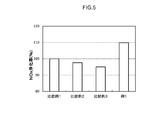
- FIG. 5 is a graph comparing the NO x purification rates of Comparative Examples 1 to 3 and Example 1.
- FIG. 6 is a graph showing the relationship between the length in the extending direction of the first catalyst layer and the NO x purification rate.
- FIG. 7 is a graph comparing HC purification rates of Comparative Examples 1 to 2, Example 1, and Example 5.
- FIG. 1 is a schematic view showing the structure of an exhaust gas purification apparatus 1 and the periphery thereof.
- the exhaust gas purification device 1 is provided in an exhaust system of an internal combustion engine (engine) 2.
- the internal combustion engine 2 is supplied with a mixture containing oxygen and fuel gas.
- the internal combustion engine 2 burns the mixture and converts the combustion energy into mechanical energy. At this time, the burned air-fuel mixture becomes exhaust gas and is discharged to the exhaust system.
- the internal combustion engine 2 of the present embodiment is mainly configured of a gasoline engine of a car.
- the internal combustion engine 2 may be, for example, an engine other than a gasoline engine (such as a diesel engine).
- the exhaust gas purification device 1 purifies harmful components contained in the exhaust gas, such as hydrocarbons (HC), carbon monoxide (CO), and nitrogen oxides (NO x ), and is included in the exhaust gas discharged from the internal combustion engine 2 Trapped particulate matter (PM).
- the exhaust gas purification device 1 has an exhaust path (exhaust manifold 3 and exhaust pipe 4) for communicating the internal combustion engine 2 with the exhaust system, an engine control unit (ECU) 5, an upstream catalyst 9, and a gasoline particulate filter (GPF). ) And 10).
- ECU engine control unit
- GPF gasoline particulate filter
- the arrow in the figure has shown the distribution direction of waste gas.
- the exhaust path of the present embodiment includes an exhaust manifold 3 and an exhaust pipe 4. That is, one end of an exhaust manifold 3 is connected to an exhaust port (not shown) communicating with the exhaust system of the internal combustion engine 2. The other end of the exhaust manifold 3 is connected to the exhaust pipe 4.
- An upstream catalyst 9 and a GPF 10 are disposed in the middle of the exhaust pipe 4.
- the GPF 10 is an example of an exhaust gas purification catalyst.
- the configuration of the upstream catalyst 9 may be the same as that of the prior art, and is not particularly limited.
- Upstream catalyst 9 is, for example, conventionally known oxidation catalyst (DOC: Diesel Oxidation Catalyst), 3 -way catalysts, NO x adsorption and reduction catalyst (LNT: Lean NOx Trap), or the like.
- the upstream side catalyst 9 may include, for example, a carrier and a noble metal supported on the carrier, such as rhodium (Rh), palladium (Pd), platinum (Pt) or the like.
- the upstream catalyst 9 may have a function of, for example, raising the temperature of the exhaust gas flowing into the GPF 10 when the GPF 10 is regenerated.
- the upstream catalyst 9 is not necessarily required and may be omitted.
- a downstream catalyst can be disposed downstream of the GPF 10.
- the ECU 5 is electrically connected to the exhaust gas purification device 1 and the internal combustion engine 2.
- the ECU 5 controls the exhaust gas purification device 1 and the internal combustion engine 2.
- the configuration of the ECU 5 may be the same as the conventional one, and is not particularly limited.
- the ECU 5 is, for example, a digital computer.
- the ECU 5 is provided with an input port (not shown).
- the ECU 5 is electrically connected to sensors (for example, pressure sensors 8) installed in the exhaust gas purification device 1 and each part of the internal combustion engine 2. Thereby, the information detected by each sensor is transmitted to the ECU 5 as an electric signal through the input port.
- the ECU 5 is provided with an output port (not shown).
- the ECU 5 transmits a control signal via the output port.
- the ECU 5 controls the start and stop of the exhaust gas purification device 1 according to, for example, the amount of exhaust gas discharged from the internal combustion engine 2 and the like.
- FIG. 2 is a perspective view of the GPF 10.
- FIG. 3 is a partial cross-sectional view in which a part of a cross section obtained by cutting the GPF 10 in the cylinder axial direction is enlarged.
- the flow direction of the exhaust gas is drawn in the arrow direction. That is, the left side of FIGS. 2 and 3 is the upstream side (front side) of the exhaust pipe 4 and the right side is the downstream side (rear side) of the exhaust pipe 4.
- symbol X represents the cylinder axial direction of GPF10, in other words the extending
- the symbol Y is a direction orthogonal to the symbol X, and represents a direction from the surface of the partition wall 16 in contact with the ingress cell 12 to the surface in contact with the outlet cell 14, in other words, the thickness direction of the partition 16 .
- this is only for the convenience of description and does not limit the installation form of the GPF 10 in any way.
- the GPF 10 has a function of purifying harmful components contained in the exhaust gas and collecting particulate matter (PM) contained in the exhaust gas.
- the GPF 10 includes a substrate 11 having a wall flow structure, a first catalyst layer 20, and a second catalyst layer 30.
- the base material 11 constitutes the framework of the GPF 10.
- the substrate 11 is a honeycomb structure.
- the base material 11 those of various materials and forms conventionally used for this type of application can be appropriately adopted.
- a ceramic made of cordierite, aluminum titanate, silicon carbide (SiC) or the like, or a high heat resistant material represented by an alloy such as stainless steel can be employed.
- the base 11 of the present embodiment has a cylindrical outer shape as a whole.
- the entire outer shape of the substrate 11 is not particularly limited, and may be, for example, an elliptical cylinder, a polygonal cylinder, or the like.
- the base material 11 partitions the inlet cell 12 in which the end 13 at the exhaust gas inlet side is open, the outlet cell 14 in which the end 15 at the exhaust gas outlet side is open, and the inlet cell 12 and the outlet cell 14. And 16).
- the shapes of the ingress cell 12 and the egress cell 14 are not particularly limited. For example, various geometrical shapes such as square, parallelogram, rectangular, rectangular shape such as trapezoid, triangular shape, other polygonal shape (for example, hexagonal, octagonal), circular, etc. can be used.
- a sealing portion 12 a is disposed and sealed at an end portion on the exhaust gas outflow side of the inlet cell 12.
- a sealing portion 14 a is disposed and sealed at an end portion on the exhaust gas inflow side of the outlet side cell 14.
- the partition wall 16 divides the entry side cell 12 and the exit side cell 14.
- the partition 16 has a porous structure through which the exhaust gas can pass.
- the porosity of the partition walls 16 is not particularly limited, but it is preferably about 20 to 70% by volume, for example 50 to 65% by volume, from the viewpoint of reducing pressure loss and the like.
- the average pore diameter of the partition walls 16 is not particularly limited, but it is preferably about 5 to 30 ⁇ m, for example 10 to 20 ⁇ m, from the viewpoint of reducing pressure loss and the like.
- the partition wall 16 extends in the cylinder axial direction of the GPF 10, that is, in the X direction.
- the total length L w in the X direction of the partition wall 16 is not particularly limited, but may be approximately 10 to 500 mm, for example, approximately 50 to 300 mm.
- the length in the Y direction of the partition wall 16, that is, the thickness T w of the partition wall 16 is not particularly limited, but it is preferably about 1 to 30 mils (1 mil is about 25.4 ⁇ m) from the viewpoint of reducing pressure loss.
- the first catalyst layer 20 and the second catalyst layer 30 are both disposed inside the partition wall 16.
- the catalyst layer is disposed inside the partition wall means that the catalyst layer is mainly present inside the partition wall 16. More specifically, for example, when the cross section of the first catalyst layer 20 or the second catalyst layer 30 is observed with an electron microscope, it is along the X direction from the end 13 at the exhaust gas inflow side or the end 15 at the exhaust gas outflow side.
- the ratio of the metal catalyst present in the inside of the partition 16 is typically 80% by mass or more, for example, 90% by mass, when the total amount of the metal catalyst in the range of 0.1 L w is 100% by mass. This means that the content is preferably 95% by mass or more. Therefore, for example, as a result of placing the catalyst layer on the outside (typically on the surface) of the partition 16, a clear distinction is made from the case where a part of the catalyst layer unintentionally erodes into the inside of the partition 16. It is
- the first catalyst layer 20 and the second catalyst layer 30 each contain a metal catalyst.
- the metal catalyst is, for example, a reaction catalyst for purifying (detoxifying) harmful components in the exhaust gas, or burning / removing PM collected in the pores of the partition wall 16.
- metal catalyst metal species conventionally known to be usable as an oxidation catalyst or a reduction catalyst in this type of field can be appropriately adopted.
- Preferred examples of the metal catalyst include platinum group Rh, Pd, Pt, ruthenium (Ru), osmium (Os), iridium (Ir) and alloys thereof.
- the metal catalyst may be, for example, iron (Fe), cobalt (Co), nickel (Ni), copper (Cu), silver (Ag), gold (Au) in addition to or in place of the platinum group. Etc. may be included.
- the first catalyst layer 20 and the second catalyst layer 30 contain mutually different metal species.
- one of the first catalyst layer 20 and the second catalyst layer 30 contains an oxidation catalyst and does not contain a reduction catalyst.
- the other contains a reduction catalyst and does not contain an oxidation catalyst.
- grain growth (sintering) or alloying of the metal catalyst can be suppressed, and a wide contact area with the exhaust gas can be secured. Thereby, the desired catalytic activity can be stably expressed over a long period of time. Therefore, the durability of the GPF 10 can be improved.
- Preferred examples of the oxidation catalyst include Pd, Pt and Pd—Pt alloys.
- the reduction catalyst may be a metal catalyst having a reduction performance higher than that of the oxidation catalyst.
- One preferred example of the reduction catalyst is Rh.
- the first catalyst layer 20 comprises a reduction catalyst, such as Rh.
- the second catalyst layer 30 contains an oxidation catalyst, for example, at least one of Pd and Pt.
- the first catalyst layer 20 does not contain an oxidation catalyst
- the second catalyst layer 30 does not contain a reduction catalyst. According to this aspect, it is possible to especially to remove the NO x well in the exhaust gas.
- the first catalyst layer 20 comprises an oxidation catalyst, such as at least one of Pd and Pt.
- the second catalyst layer 30 contains a reduction catalyst such as Rh.
- the first catalyst layer 20 does not contain a reduction catalyst
- the second catalyst layer 30 does not contain an oxidation catalyst. According to this aspect, HC and CO in the exhaust gas can be purified particularly well.
- the oxidation catalyst and the reduction catalyst are typically supported on a carrier.
- a carrier those conventionally known to be usable for this type of application can be suitably employed.
- metal oxides such as alumina (Al 2 O 3 ), ceria (CeO 2 ), zirconia (ZrO 2 ), silica (SiO 2 ), titania (TiO 2 ), and their solid solutions such as zirconia-ceria composite oxide (ZC complex oxide: ZrO 2 -CeO 2 ) can be suitably employed.
- alumina and ZC composite oxide are preferable.
- the first catalyst layer 20 and the second catalyst layer 30 may each optionally contain an optional component in addition to the metal catalyst and the carrier supporting the metal catalyst.
- optional components include cocatalyst metal catalyst is not supported, the oxygen storage material having an oxygen storage capacity (OSC material: oxygen storage capacity), NO x adsorbent with the NO x storage capacity, such as a stabilizer Can be mentioned.
- the cocatalyst include alumina and silica.
- the OSC material include ceria and composite oxides containing ceria, such as ZC composite oxides.
- the stabilizer examples include rare earth elements such as lanthanum (La) and yttrium (Y), alkaline earth elements such as calcium (Ca) and barium (Ba), and other transition metal elements. These elements are present in the catalyst layer, typically in the form of oxides.
- the catalyst layer containing an oxidation catalyst preferably contains a stabilizer, for example, barium element.
- a stabilizer for example, barium element.
- the coating amount of each of the first catalyst layer 20 and the second catalyst layer 30 is not particularly limited. From the viewpoint of enhancing the flowability of the exhaust gas of the partition wall 16 and further reducing the pressure loss, the volume per unit volume (total bulk volume including the volume of the cells) per liter is about 100 g / L or less, preferably It is good to set it as 80 g / L or less, for example, 70 g / L or less. On the other hand, from the viewpoint of further improving the exhaust gas purification performance, the volume per liter of the base material is preferably about 5 g / L or more, preferably 10 g / L or more, for example 20 g / L or more.
- the first catalyst layer 20 is disposed along the extending direction (X direction) of the partition wall 16 from the end 13 at the exhaust gas inflow side.
- the first catalyst layer 20 of FIG. 3 has a substantially inverted trapezoidal cross-sectional shape. In other words, the first catalyst layer 20 is disposed so that the length in the X direction gradually decreases from the surface of the partition wall 16 in contact with the inlet cell 12 to the surface of the partition wall 16 in contact with the outlet cell 14.
- the second catalyst layer 30 is disposed along the extending direction (X direction) of the partition wall 16 from the end portion 15 on the exhaust gas outflow side.
- the second catalyst layer 30 of FIG. 3 has a substantially trapezoidal cross-sectional shape. In other words, the second catalyst layer 30 is disposed so that the length in the X direction gradually increases from the surface of the partition wall 16 in contact with the inlet cell 12 to the surface of the partition wall 16 in contact with the outlet cell 14. .
- the first catalyst layer 20 and the second catalyst layer 30 are disposed to be in contact with the inlet cell 12 and the outlet cell 14, respectively.
- the maximum thickness (the maximum length in the Y direction) of the first catalyst layer 20 is the same as the thickness T w of the partition wall 16.
- the maximum thickness (maximum length in the Y direction) of the second catalyst layer 30 is the same as the thickness T w of the partition wall 16.
- the same as the thickness T w of the partition wall 16 is not to be strictly interpreted, and an error attributable to manufacturing accuracy or the like (approximately 0.95 T w to 1.05 T w , preferably 0.98 T w to 1.02 T w , for example, a variation of about 0.99 T w to 1.01 T w ) is acceptable.
- the area ratio of the first catalyst layer 20 to the second catalyst layer 30 is different between the surface of the partition wall 16 in contact with the inlet cell 12 and the surface of the partition wall 16 in contact with the outlet cell 14. That is, the area of the first catalyst layer 20 is A 1 -in and the area of the second catalyst layer 30 is A 2-in on the surface of the partition wall 16 in contact with the inlet cell 12. Further, on the surface of the partition wall 16 on the side in contact with the outlet cell 14, the area of the first catalyst layer 20 is A 1 -out, and the area of the second catalyst layer 30 is A 2 -out .
- the area ratio (A 1-in / A 2 -in), the value of the area ratio (A 1-out / A 2 -out) is different from each other.
- the length in the extending direction of the first catalyst layer 20 and the length in the extending direction of the second catalyst layer 30 in the surface of the partition wall 16 in contact with the inlet cell 12 and the surface in contact with the outlet cell 14 The ratio is different. That is, the length of the first catalyst layer 20 in the extending direction is L 1 -in, and the length of the second catalyst layer 30 in the extending direction is L 2-in I assume. Further, on the surface of the partition wall 16 on the side in contact with the outlet cell 14, the length in the extending direction of the first catalyst layer 20 is L 1 -out, and the length in the extending direction of the second catalyst layer 30 is L 2-out I assume.
- the values of the length ratio (L 1 -in / L 2-in ) and the length ratio (L 1 -out / L 2-out ) are different from each other.
- the catalyst layer can be dispersedly disposed in the X direction, and the pressure loss can be suitably reduced.
- the contact between the exhaust gas and the metal catalyst can be suitably enhanced to improve the exhaust gas purification performance.
- the length L 1-in the stretching direction at the surface of the side in contact with the inlet side cells 12 of the first catalyst layer 20 is: 5% ⁇
- the length L 2-out in the stretching direction of the surface on the side in contact with the outlet side cell 14 is: 5% ⁇
- the length L 1 -in of the extending direction of the first catalyst layer 20 is not particularly limited on the surface of the partition wall 16 in contact with the inlet cell 12, but in a preferred embodiment, the total length L w of the partition wall 16 in the stretching direction L 1-in is approximately 35% or more, typically 40% or more, for example 50% or more, and is shorter than L w , generally 80% or less, typically, where It is 75% or less, for example 70% or less.
- the length L 2-in of the second catalyst layer 30 in the stretching direction is not particularly limited, but in a preferred embodiment, L 2-in when the total length L w in the stretching direction of the partition walls 16 is 100%. Is approximately 20% or more, typically 25% or more, for example 30% or more, shorter than L w , approximately 65% or less, typically 60% or less, eg 50% or less.
- the first catalyst is such that L 1 -in is 40 to 75%, for example, 50% or more of the total length L w of the partition 16 on the surface of the partition 16 on the side in contact with the inlet cell 12.
- Layer 20 is disposed.
- the purification reaction can be actively generated on the upstream side of the GPF 10, that is, in the region near the end 13 on the exhaust gas inflow side.
- the reaction heat during the purification reaction can be transmitted to the downstream side of the GPF 10, that is, the area near the end 15 on the exhaust gas outflow side, and the entire catalyst can be efficiently warmed up.
- the temperature of exhaust gas tends to be unstable as the engine starts and stops.
- the exhaust gas purification performance can be more stably exhibited.
- the length L 2-in is the following formula: 0.8 L w ⁇ (L 1 -in + L 2-in ) ⁇ 1.2 L w ; for example, the following formula: 0.9 L w ⁇ (L 1 -in + L 2 -In ) ⁇ 1.1 L w ; is satisfied.
- the entire surface of the partition wall 16 in contact with the inlet cell 12 be covered with one of the first catalyst layer 20 and the second catalyst layer 30. .
- the length L 1 -in of the first catalyst layer 20 in the stretching direction is the length L of the second catalyst layer 30 in the stretching direction on the surface of the partition wall 16 in contact with the inlet cell 12.
- L 1 -in and L 2-in satisfy L 1 -in > L 2-in .
- the length L 1 -out in the stretching direction of the first catalyst layer 20 is not particularly limited on the surface of the partition wall 16 in contact with the outlet cell 14, but in a preferred embodiment, the total length L w in the stretching direction of the partition wall 16 L 1-out is approximately 25% or more, typically 30% or more, for example 40% or more, and is shorter than L w , approximately 70% or less, typically, where 65% or less, for example 60% or less.
- the length L 2-out in the stretching direction of the second catalyst layer 30 is not particularly limited, but in a preferred embodiment, L 2-out when the total length L w in the stretching direction of the partition wall 16 is 100%. Is approximately 30% or more, typically 35% or more, for example 40% or more, shorter than L w , approximately 75% or less, typically 70% or less, for example 60% or less.
- L 2-out is 35 to 70%, for example 40% or more, of the total length L w of the partition 16 on the surface of the partition 16 on the side in contact with the outlet cell 14. Is arranged. As a result, the pressure loss when the exhaust gas flows into the inlet cell 12 of the GPF 10 can be reduced better. Therefore, the reduction of pressure loss and the exhaust gas purification performance can be compatible at a higher level.
- the surface of the side in contact with the exit-side cell 14 of the partition wall 16, and the total length L w of the partition wall 16, the length L 1-out of the first catalyst layer 20, the second catalyst layer 30 The length L 2-out and the following equation: 0.8 L w ⁇ (L 1 ⁇ out + L 2 ⁇ out ) ⁇ 1.2 L w ; for example, the following equation: 0.9 L w ⁇ (L 1 ⁇ out + L 2 -Out ) ⁇ 1.1 L w ; is satisfied.
- the entire surface of the partition wall 16 in contact with the outlet cell 14 be covered with one of the first catalyst layer 20 and the second catalyst layer 30. .
- any one of the first catalyst layer 20 and the second catalyst layer 30 is disposed over the entire partition wall 16, that is, the entire extension direction and thickness direction. According to such a configuration, the pressure loss can be better reduced, and harmful components can be removed from the exhaust gas with high probability. In addition, exhaust gas can be better suppressed from passing through the portion where the catalyst layer is not disposed and being discharged with insufficient purification.
- the GPF 10 further includes a third catalyst layer 40 in which the first catalyst layer 20 and the second catalyst layer 30 overlap.
- the third catalyst layer 40 is to form a catalyst layer over the entire partition wall 16, the first catalyst layer 20 and the second catalyst layer are formed in the vicinity of the interface between the first catalyst layer 20 and the second catalyst layer 30. 30 is an overlapping area. Since the third catalyst layer 40 includes both the oxidation catalyst and the reduction catalyst, the third catalyst layer 40 is grasped as a catalyst layer different from the first catalyst layer 20 and the second catalyst layer 30.
- the third catalyst layer 40 is generally 10% or more, for example 20% or more, when the entire volume of the partition 16 is 100%. In one example, it may be 30% or more, and generally 80% or less, for example 70% or less, in one example 60% or less.
- the GPF 10 having the above-described configuration can be manufactured, for example, by the following method.
- a base material 11 as shown in FIG. 2 is prepared.
- two types of catalyst layer forming slurries namely, a first slurry and a second slurry are prepared.
- the slurry for forming a catalyst layer contains mutually different metal catalyst components (typically, a solution containing a metal catalyst as an ion) as an essential component, and each of the other optional components such as a carrier, cocatalyst, OSC material, binder , Various additives and the like.
- the properties of the slurry (such as viscosity and solid content) may be appropriately adjusted depending on the size of the substrate 11 to be used, the porosity of the partition walls 16, the desired properties of the catalyst layer 20, and the like.
- the first slurry and the second slurry each have a temperature of 25 ° C. and a shear rate of 400 s ⁇ 1 .
- Low viscosity with a viscosity 400 400 of 50 mPa ⁇ s or less preferably 30 mPa ⁇ s or less, more preferably 20 mPa ⁇ s or less, especially 15 mPa ⁇ s or less (eg 1 to 15 mPa ⁇ s)
- the viscosity of the first slurry and the viscosity of the second slurry may be approximately equal (typically, the difference between the two is 10 mPa ⁇ s or less, for example, the difference between the two is 5 mPa ⁇ s or less).
- the said slurry viscosity is a viscosity measured using a commercial shear viscometer in a temperature environment of 25 degreeC.
- the prepared first slurry is made to flow from the end portion 13 on the exhaust gas inflow side of the base material 11 into the inlet cell 12 and supplied to the predetermined length L 1 -in of the partition 16 along the X direction. Then, suction is performed from the side of the outlet cell 14 to generate a pressure difference between the inlet cell 12 and the outlet cell 14.
- the suction speed of the slurry may be approximately 10 to 100 m / s, preferably 10 to 80 m / s, for example 50 m / s or less, from the viewpoint of suitably forming the first catalyst layer 20 having the cross-sectional shape described above.
- the first slurry is distributed in the pores of the partition wall 16.
- the base material 11 to which the first slurry is applied is dried and fired at a predetermined temperature and time.
- the method of drying and calcination may be the same as in the conventional catalyst layer formation.
- the first catalyst layer 20 having a substantially inverted trapezoidal cross-sectional shape is formed inside the partition wall 16.
- the prepared second slurry is allowed to flow into the outlet cell 14 from the end portion 15 on the exhaust gas outflow side of the base material 11 and supplied to the predetermined length L 2-out of the partition wall 16 along the X direction.
- the length L 2-out for supplying the second slurry may be determined by subtracting the length L 1-out of the portion where the first catalyst layer 20 is formed from the total length L w in the X direction of the partition wall 16. Then, a pressure difference is generated between the outlet cell 14 and the inlet cell 12 by suction from the inlet cell 12 side.
- the suction speed of the slurry may be approximately 10 to 100 m / s, preferably 10 to 80 m / s, for example 50 m / s or less, from the viewpoint of suitably forming the second catalyst layer 30 having the cross-sectional shape described above.
- the second slurry is distributed in the pores of the partition wall 16.
- the substrate 11 to which the second slurry is applied is dried and fired at a predetermined temperature and time.
- the method of drying and calcination may be the same as in the conventional catalyst layer formation.
- the second catalyst layer 30 having a substantially trapezoidal cross-sectional shape is formed inside the partition wall 16.
- the exhaust gas discharged from the internal combustion engine 2 flows into the inlet cell 12 from the end 13 at the exhaust gas inlet side.
- the exhaust gas having flowed into the inlet cell 12 passes through the porous partition 16 and reaches the outlet cell 14.
- the first catalyst layer 20 and the second catalyst layer 30 are disposed inside the partition wall 16. Therefore, harmful components and PM are removed from the exhaust gas while the exhaust gas passes through the first catalyst layer 20 and / or the second catalyst layer 30 in the partition wall 16.
- the exhaust gas that has passed through the partition wall 16 and reaches the outlet cell 14 is discharged from the end portion 15 on the exhaust gas outlet side to the outside of the GPF 10 in a state where harmful components and PM are removed.
- test example regarding this invention is demonstrated, it is not intending limiting this invention to what is shown to the following test example.
- Test Example I-1 First, as Comparative Examples 1 to 3, a catalyst for purifying an exhaust gas including an oxidation catalyst and a reduction catalyst in the same catalyst layer was produced. Specifically, first, a wall flow type cordierite base as shown in FIG. 2 (total length 122 mm, outer diameter 113 mm, volume 1.3 L, cell number 300 cells / in 2 , average pore diameter 20 ⁇ m, porosity 65) Prepared).
- the prepared slurry A is allowed to flow into the inlet cell from the end portion on the exhaust gas inflow side of the cordierite base material, and the base material is drawn along the stretching direction of the partition wall by the vacuum suction method.
- the catalyst layer was formed by coating the inside of the partition wall with the same length as the total length L w, and drying and calcining.
- the coating amount of the catalyst layer per unit volume of the substrate was 88.5 g / L.
- the maximum thickness of the catalyst layer was 50% of the thickness T w of the partition wall in Comparative Example 1, and the same thickness T w as the partition wall in Comparative Example 2. That is, in Comparative Example 1, the catalyst layer is in contact with the ingress cell and not in contact with the egress cell. In Comparative Example 2, the catalyst layer is in contact with the ingress cell and the egress cell.
- the exhaust gas purifying catalyst of Comparative Examples 1 and 2 having a single catalyst layer was produced.
- the prepared slurry A is allowed to flow into the inlet cell from the end portion of the cordierite substrate on the exhaust gas inflow side, and the entire length L of the substrate along the stretching direction of the partition wall by the vacuum suction method.
- the inlet catalyst layer was formed by coating the inside of the partition wall corresponding to 55% of w , drying and calcining.
- the prepared slurry A is allowed to flow into the outlet side cell from the end on the exhaust gas outflow side, and the inside of the partition corresponding to 55% of the total length L w of the base material along the stretching direction of the partition By coating, drying and calcining, an outlet catalyst layer was formed.
- the coating amount of the inlet catalyst layer and the outlet catalyst layer per unit volume of the substrate was set to half (44.25 g / L) of Comparative Examples 1 and 2, respectively.
- the maximum thickness of the inlet side catalyst layer and the outlet side catalyst layer was set to be the same thickness T w as the partition walls.
- alumina powder ⁇ -Al 2 O 3
- rhodium nitrate solution 0.2 g in Rh conversion
- the prepared Rh slurry is allowed to flow into the inlet cell from the end portion of the cordierite substrate on the exhaust gas inflow side, and coated inside the partition along the extending direction of the partition by vacuum suction method, dried and fired
- the first catalyst layer was formed inside the partition wall to be in contact with the ingress cell and the egress cell.
- the coating amount of the 1st catalyst layer per unit volume of a base material was 60.2 g / L.
- the first catalyst layer was formed at a portion corresponding to 70% (0.7 L w ) of the total length L w of the base on the surface of the partition in contact with the entry side cell.
- the maximum thickness of the first catalyst layer was the same as the thickness T w of the partition walls.
- the prepared Pd slurry is allowed to flow into the outlet cell from the end of the cordierite base material on the exhaust gas outlet side, and coated inside the partition along the extending direction of the partition by vacuum suction method, dried and fired
- the second catalyst layer was formed inside the partition wall so as to be in contact with the ingress cell and the egress cell.
- the coating amount of the 2nd catalyst layer per unit volume of a base material was 28.3 g / L.
- the second catalyst layer was formed at a portion corresponding to 40% (0.4 L w ) of the total length L w of the base on the surface of the partition in contact with the outlet cell.
- the maximum thickness of the second catalyst layer was the same as the thickness T w of the partition walls.
- the pressure loss increase rate of the catalyst for exhaust gas purification prepared above was measured. Specifically, first, a honeycomb substrate (reference) before coating the catalyst layer was prepared, and the pressure was measured when air was circulated at an air volume of 6 m 3 / min. Next, using the catalyst for exhaust gas purification (the honeycomb substrate with a catalyst layer) manufactured as described above, the pressure when air was circulated at an air flow rate of 6 m 3 / min was measured in the same manner as the reference. Then, the pressure loss increase rate (%) was calculated from the following equation: [(pressure of exhaust gas purification catalyst ⁇ pressure of reference) / pressure of reference] ⁇ 100; The pressure loss increase rate indicates that the smaller the numerical value, the more preferable the pressure loss increase. The results are shown in the corresponding column of Table 1. In Table 1, it represents with the relative value which made the pressure loss increase rate of the comparative example 1 the reference
- FIG. 4 is a graph comparing the pressure drop increase rates of Comparative Examples 1 to 3 and Example 1. As shown in Table 1 and FIG. 4, in Example 1 and Comparative Examples 2 to 3, the pressure loss increase rate was reduced to about half that of Comparative Example 1. Among them, Example 1 had the smallest value of the pressure drop increase rate. As a reason for this, in Comparative Example 1 in which the catalyst layer not in contact with the outlet cell is formed, it is conceivable that the flow path of the exhaust gas is narrowed at the portion where the catalyst layer is formed, and the inflow of exhaust gas becomes disadvantageous.
- Example 1 in which the catalyst layer is formed to have the same thickness as the partition wall so as to be in contact with the inlet cell and the outlet cell, the flow path of the exhaust gas in the partition wall is relative even after the catalyst layer is formed. It can be considered that it was widely secured.
- each exhaust gas purification catalyst is installed in the exhaust path of a gasoline direct injection vehicle, and the temperature of the gas entering the catalyst is raised from 100 ° C. to 520 ° C. at a heating rate of 10 ° C./min using a heat exchanger. I let it warm.
- the purification rate of the NO x component is continuously measured from the ratio of the inflow gas concentration to the outgas concentration at this time, and the catalyst gas temperature when the purification rate of the NO x component reaches 50% (T 50 ⁇ NO x ) was evaluated.
- FIG. 5 is a graph comparing the NO x purification rates of Comparative Examples 1 to 3 and Example 1.
- the NO x purification rate was significantly improved as compared with Comparative Examples 1 to 3.
- Comparative Example 1 it is considered that the frequency of contact of the exhaust gas with the catalyst layer was relatively low.
- Comparative Examples 2 and 3 it is considered that particle growth and alloying of the metal catalyst occur and the contact frequency of the exhaust gas to the metal catalyst is reduced by arranging the oxidation catalyst and the reduction catalyst in the entire partition wall.
- the frequency of contact of the exhaust gas with the metal catalyst is improved by dividing and arranging the oxidation catalyst and the reduction catalyst in the extending direction of the partition walls.
- Test Example I-2 With respect to the first catalyst layer and the second catalyst layer, the length in the stretching direction of the partition wall (L 1 -in , L 1 -out , L 2-in , L 2-out ) was changed as shown in Table 2. In the same manner as in Example 1, an exhaust gas purifying catalyst of Examples 2 to 4 was produced. Then, the exhaust gas purification performance was evaluated in the same manner as in the above-described Test Example I-1. The results are shown in the corresponding column of Table 2. In Table 2, it indicated as a relative value based on (100%) of the NO x purification rate of Comparative Example 1.
- FIG. 6 is a graph showing the relationship between the length in the extending direction of the first catalyst layer and the NO x purification rate.
- Table 2 and FIG. 6 an example 1-4 is approximately equivalent of the NO x purification rate, both also the NO x purification rate approximately 10% compared to Comparative Example 1 was improved. Therefore, from the viewpoint of the NO x purification performance, when the total length L w of the partition in the stretching direction is 100%, the length L of the first catalyst layer in the stretching direction on the surface of the partition in contact with the entry side cell. It can be said that 1-in is 50 to 75%.
- Example II The exhaust gas purification catalyst of Example 5 was produced by inverting the first catalyst layer and the second catalyst layer of Example 1. Then, the pressure loss and the exhaust gas purification performance were evaluated in the same manner as in the above-described Test Example I-1.
- the purification rate of the NO x component instead of the purification rate of the NO x component, the purification rate of the HC component (HC purification rate) was evaluated according to the above-mentioned Test Example I-1.
- Table 3 it represents with the relative value which made HC purification rate of comparative example 1 a standard (100%).
- the HC purification rate is expressed such that the higher the HC purification performance, the larger the value.
- FIG. 7 is a graph comparing HC purification rates of Comparative Examples 1 to 2, Example 1, and Example 5. As shown in Table 3 and FIG. 7, in Example 5, the HC purification rate was further improved than in Example 1. Therefore, from the viewpoint of HC purification performance, it may be preferable to dispose an oxidation catalyst in the first catalyst layer.
- the GPF 10 further includes the third catalyst layer 40 in addition to the first catalyst layer 20 and the second catalyst layer 30, but the present invention is not limited thereto.
- the GPF 10 may include only two catalyst layers, that is, the first catalyst layer 20 and the second catalyst layer 30.
- the exhaust gas purification catalyst is GPF 10, but is not limited thereto.
- the exhaust gas purification catalyst may be a diesel particulate filter (DPF: Diesel Particulate Filter).
- 1 exhaust gas purification apparatus 2 internal combustion engine, 10 GPF (catalyst for exhaust gas purification), 11 base materials, 12 inlet cells, 14 outlet cells, 16 partitions, 20 first catalyst layer, 30 second catalyst layer
Landscapes
- Engineering & Computer Science (AREA)
- Chemical & Material Sciences (AREA)
- Chemical Kinetics & Catalysis (AREA)
- Combustion & Propulsion (AREA)
- Mechanical Engineering (AREA)
- General Engineering & Computer Science (AREA)
- Health & Medical Sciences (AREA)
- Materials Engineering (AREA)
- Toxicology (AREA)
- Organic Chemistry (AREA)
- Ceramic Engineering (AREA)
- Biomedical Technology (AREA)
- Environmental & Geological Engineering (AREA)
- Analytical Chemistry (AREA)
- General Chemical & Material Sciences (AREA)
- Oil, Petroleum & Natural Gas (AREA)
- Catalysts (AREA)
- Exhaust Gas After Treatment (AREA)
- Exhaust Gas Treatment By Means Of Catalyst (AREA)
- Processes For Solid Components From Exhaust (AREA)
Abstract
La présente invention concerne un catalyseur de purification de gaz d'échappement 10 comprenant : un substrat 11 qui a une structure à écoulement de paroi dans laquelle une cellule côté entrée 12, qui a une ouverture au niveau d'une section d'extrémité 13 sur un côté d'entrée de gaz d'échappement, et une cellule côté sortie 14, qui a une ouverture au niveau d'une section d'extrémité 15 sur un côté de sortie de gaz d'échappement, sont séparées par une cloison poreuse 16; et une première couche de catalyseur 20 et une seconde couche de catalyseur 30 qui sont disposées à l'intérieur de la cloison 16 de façon à entrer en contact avec la cellule côté entrée 12 et la cellule côté sortie 14, l'une de la première couche de catalyseur 20 et de la seconde couche de catalyseur 30 contenant un catalyseur d'oxydation et ne contenant pas de catalyseur de réduction, et l'autre contenant un catalyseur de réduction et ne contenant pas de catalyseur d'oxydation, et les rapports entre la longueur de la première couche de catalyseur 20 et celle de la seconde couche de catalyseur 30 étant différents entre une surface de la cloison 16 sur le côté qui vient en contact avec la cellule côté entrée 12 et une surface de la cloison 16 sur le côté qui vient en contact avec la cellule côté sortie 14.
Priority Applications (3)
| Application Number | Priority Date | Filing Date | Title |
|---|---|---|---|
| US16/647,004 US11187129B2 (en) | 2017-09-28 | 2018-09-11 | Exhaust gas purification catalyst |
| CN201880062609.8A CN111148571B (zh) | 2017-09-28 | 2018-09-11 | 排气净化用催化剂 |
| EP18860962.2A EP3689457B1 (fr) | 2017-09-28 | 2018-09-11 | Catalyseur de purification de gaz d'échappement |
Applications Claiming Priority (2)
| Application Number | Priority Date | Filing Date | Title |
|---|---|---|---|
| JP2017189040A JP6487982B1 (ja) | 2017-09-28 | 2017-09-28 | 排ガス浄化用触媒 |
| JP2017-189040 | 2017-09-28 |
Publications (1)
| Publication Number | Publication Date |
|---|---|
| WO2019065206A1 true WO2019065206A1 (fr) | 2019-04-04 |
Family
ID=65802350
Family Applications (1)
| Application Number | Title | Priority Date | Filing Date |
|---|---|---|---|
| PCT/JP2018/033544 WO2019065206A1 (fr) | 2017-09-28 | 2018-09-11 | Catalyseur de purification de gaz d'échappement |
Country Status (5)
| Country | Link |
|---|---|
| US (1) | US11187129B2 (fr) |
| EP (1) | EP3689457B1 (fr) |
| JP (1) | JP6487982B1 (fr) |
| CN (1) | CN111148571B (fr) |
| WO (1) | WO2019065206A1 (fr) |
Cited By (2)
| Publication number | Priority date | Publication date | Assignee | Title |
|---|---|---|---|---|
| CN113840643A (zh) * | 2019-06-18 | 2021-12-24 | 株式会社科特拉 | 微粒过滤器 |
| WO2023067744A1 (fr) * | 2021-10-20 | 2023-04-27 | 三井金属鉱業株式会社 | Catalyseur de purification de gaz d'échappement |
Families Citing this family (7)
| Publication number | Priority date | Publication date | Assignee | Title |
|---|---|---|---|---|
| EP3501647A1 (fr) | 2017-12-19 | 2019-06-26 | Umicore Ag & Co. Kg | Filtre à particules catalityquement actif |
| EP3501648B1 (fr) | 2017-12-19 | 2023-10-04 | Umicore Ag & Co. Kg | Filtre à particules catalityquement actif |
| EP3505245B1 (fr) | 2017-12-19 | 2019-10-23 | Umicore Ag & Co. Kg | Filtre à particules à effet catalytique actif |
| EP3737491B1 (fr) * | 2019-03-29 | 2022-05-11 | UMICORE AG & Co. KG | Filtre à particules à activité catalytique |
| JP7414413B2 (ja) * | 2019-06-26 | 2024-01-16 | 株式会社キャタラー | パティキュレートフィルタ |
| CN111997718B (zh) * | 2020-08-18 | 2022-05-17 | 无锡威孚环保催化剂有限公司 | 一种应用于柴油-天然气双燃料车的后处理方法 |
| JP7373081B2 (ja) | 2020-12-28 | 2023-11-01 | 三菱重工エンジン&ターボチャージャ株式会社 | タービンハウジング、ターボチャージャおよびガソリンエンジン |
Citations (8)
| Publication number | Priority date | Publication date | Assignee | Title |
|---|---|---|---|---|
| JP2007185571A (ja) | 2006-01-11 | 2007-07-26 | Toyota Central Res & Dev Lab Inc | 排ガス浄化用触媒及びその製造方法 |
| JP2009082915A (ja) | 2007-09-27 | 2009-04-23 | Umicore Ag & Co Kg | 主として化学量論的空気/燃料混合物により運転される内燃機関エンジンの排ガスからの粒子の除去 |
| JP2012172597A (ja) * | 2011-02-22 | 2012-09-10 | Honda Motor Co Ltd | 排気浄化フィルタ |
| WO2015087816A1 (fr) * | 2013-12-11 | 2015-06-18 | 株式会社キャタラー | Matériau de purification de gaz d'échappement |
| WO2016060050A1 (fr) * | 2014-10-16 | 2016-04-21 | 株式会社キャタラー | Catalyseur pour purification des gaz d'échappement |
| WO2016133085A1 (fr) * | 2015-02-17 | 2016-08-25 | 株式会社キャタラー | Catalyseur de purification de gaz d'échappement |
| JP2017144377A (ja) * | 2016-02-16 | 2017-08-24 | 日本碍子株式会社 | ハニカム構造体 |
| JP2017189040A (ja) | 2016-04-06 | 2017-10-12 | 矢崎総業株式会社 | ケーブル配索構造 |
Family Cites Families (14)
| Publication number | Priority date | Publication date | Assignee | Title |
|---|---|---|---|---|
| WO2008011146A1 (fr) * | 2006-07-21 | 2008-01-24 | Dow Global Technologies Inc. | Filtre à suies perfectionné à zone catalysée |
| US20080078171A1 (en) * | 2006-09-29 | 2008-04-03 | Dacosta Herbert F M | Chemically functionalized filter system |
| JP2009287402A (ja) | 2008-05-27 | 2009-12-10 | Nissan Motor Co Ltd | 排気浄化用フィルタ及び排気浄化装置 |
| KR101765354B1 (ko) * | 2009-11-20 | 2017-08-07 | 바스프 에스이 | 존형 촉매화 매연 필터 |
| GB2492175B (en) * | 2011-06-21 | 2018-06-27 | Johnson Matthey Plc | Exhaust system for internal combustion engine comprising catalysed filter substrate |
| US8789356B2 (en) * | 2011-07-28 | 2014-07-29 | Johnson Matthey Public Limited Company | Zoned catalytic filters for treatment of exhaust gas |
| US9347357B2 (en) * | 2012-09-27 | 2016-05-24 | Ngk Insulators, Ltd. | Honeycomb catalyst body |
| GB201221025D0 (en) * | 2012-11-22 | 2013-01-09 | Johnson Matthey Plc | Zoned catalysed substrate monolith |
| US10125649B2 (en) * | 2014-10-16 | 2018-11-13 | Cataler Corporation | Exhaust gas purification catalyst |
| JP6353918B2 (ja) * | 2014-10-16 | 2018-07-04 | 株式会社キャタラー | 排ガス浄化用触媒 |
| JP6565184B2 (ja) | 2014-12-26 | 2019-08-28 | 日産自動車株式会社 | ハニカム型モノリス触媒およびその製造方法 |
| CN107249738B (zh) | 2015-02-17 | 2020-10-20 | 株式会社科特拉 | 排气净化用催化剂 |
| RU2019139697A (ru) | 2015-06-18 | 2020-01-10 | Джонсон Мэтти Паблик Лимитед Компани | Зонированная система выпуска отработавших газов |
| JP6297767B2 (ja) | 2016-03-24 | 2018-03-20 | 株式会社キャタラー | 排ガス浄化装置 |
-
2017
- 2017-09-28 JP JP2017189040A patent/JP6487982B1/ja active Active
-
2018
- 2018-09-11 US US16/647,004 patent/US11187129B2/en active Active
- 2018-09-11 WO PCT/JP2018/033544 patent/WO2019065206A1/fr unknown
- 2018-09-11 CN CN201880062609.8A patent/CN111148571B/zh active Active
- 2018-09-11 EP EP18860962.2A patent/EP3689457B1/fr active Active
Patent Citations (8)
| Publication number | Priority date | Publication date | Assignee | Title |
|---|---|---|---|---|
| JP2007185571A (ja) | 2006-01-11 | 2007-07-26 | Toyota Central Res & Dev Lab Inc | 排ガス浄化用触媒及びその製造方法 |
| JP2009082915A (ja) | 2007-09-27 | 2009-04-23 | Umicore Ag & Co Kg | 主として化学量論的空気/燃料混合物により運転される内燃機関エンジンの排ガスからの粒子の除去 |
| JP2012172597A (ja) * | 2011-02-22 | 2012-09-10 | Honda Motor Co Ltd | 排気浄化フィルタ |
| WO2015087816A1 (fr) * | 2013-12-11 | 2015-06-18 | 株式会社キャタラー | Matériau de purification de gaz d'échappement |
| WO2016060050A1 (fr) * | 2014-10-16 | 2016-04-21 | 株式会社キャタラー | Catalyseur pour purification des gaz d'échappement |
| WO2016133085A1 (fr) * | 2015-02-17 | 2016-08-25 | 株式会社キャタラー | Catalyseur de purification de gaz d'échappement |
| JP2017144377A (ja) * | 2016-02-16 | 2017-08-24 | 日本碍子株式会社 | ハニカム構造体 |
| JP2017189040A (ja) | 2016-04-06 | 2017-10-12 | 矢崎総業株式会社 | ケーブル配索構造 |
Non-Patent Citations (1)
| Title |
|---|
| See also references of EP3689457A4 |
Cited By (3)
| Publication number | Priority date | Publication date | Assignee | Title |
|---|---|---|---|---|
| CN113840643A (zh) * | 2019-06-18 | 2021-12-24 | 株式会社科特拉 | 微粒过滤器 |
| EP3925681A4 (fr) * | 2019-06-18 | 2022-05-25 | Cataler Corporation | Filtre à particules |
| WO2023067744A1 (fr) * | 2021-10-20 | 2023-04-27 | 三井金属鉱業株式会社 | Catalyseur de purification de gaz d'échappement |
Also Published As
| Publication number | Publication date |
|---|---|
| EP3689457A1 (fr) | 2020-08-05 |
| EP3689457A4 (fr) | 2020-10-14 |
| JP6487982B1 (ja) | 2019-03-20 |
| CN111148571A (zh) | 2020-05-12 |
| US20200263587A1 (en) | 2020-08-20 |
| CN111148571B (zh) | 2023-02-17 |
| US11187129B2 (en) | 2021-11-30 |
| EP3689457B1 (fr) | 2022-07-06 |
| JP2019063700A (ja) | 2019-04-25 |
Similar Documents
| Publication | Publication Date | Title |
|---|---|---|
| US10626765B2 (en) | Exhaust gas purification device | |
| CN106794421B (zh) | 排气净化装置 | |
| CN107249738B (zh) | 排气净化用催化剂 | |
| WO2019065206A1 (fr) | Catalyseur de purification de gaz d'échappement | |
| WO2018173557A1 (fr) | Catalyseur de purification de gaz d'échappement | |
| JPWO2015087872A1 (ja) | 排ガス浄化用触媒 | |
| JP6955573B2 (ja) | 排ガス浄化用触媒 | |
| JP6386697B1 (ja) | 排ガス浄化用触媒 | |
| WO2016056573A1 (fr) | Dispositif de purification de gaz d'échappement | |
| JP6445228B1 (ja) | 排ガス浄化用触媒 | |
| JP7130622B2 (ja) | 排ガス浄化用触媒 | |
| US11918986B2 (en) | Exhaust gas purification device | |
| JP7178432B2 (ja) | 排気浄化フィルタ |
Legal Events
| Date | Code | Title | Description |
|---|---|---|---|
| 121 | Ep: the epo has been informed by wipo that ep was designated in this application |
Ref document number: 18860962 Country of ref document: EP Kind code of ref document: A1 |
|
| NENP | Non-entry into the national phase |
Ref country code: DE |
|
| ENP | Entry into the national phase |
Ref document number: 2018860962 Country of ref document: EP Effective date: 20200428 |