WO2016133085A1 - Catalyseur de purification de gaz d'échappement - Google Patents
Catalyseur de purification de gaz d'échappement Download PDFInfo
- Publication number
- WO2016133085A1 WO2016133085A1 PCT/JP2016/054432 JP2016054432W WO2016133085A1 WO 2016133085 A1 WO2016133085 A1 WO 2016133085A1 JP 2016054432 W JP2016054432 W JP 2016054432W WO 2016133085 A1 WO2016133085 A1 WO 2016133085A1
- Authority
- WO
- WIPO (PCT)
- Prior art keywords
- exhaust gas
- catalyst layer
- catalyst
- partition wall
- osc
- Prior art date
Links
- 239000003054 catalyst Substances 0.000 title claims abstract description 456
- 238000000746 purification Methods 0.000 title claims abstract description 47
- 238000005192 partition Methods 0.000 claims abstract description 128
- 239000000463 material Substances 0.000 claims abstract description 95
- 239000000758 substrate Substances 0.000 claims abstract description 45
- 239000007789 gas Substances 0.000 claims description 199
- 239000011248 coating agent Substances 0.000 claims description 60
- 238000000576 coating method Methods 0.000 claims description 60
- QVGXLLKOCUKJST-UHFFFAOYSA-N atomic oxygen Chemical compound [O] QVGXLLKOCUKJST-UHFFFAOYSA-N 0.000 claims description 39
- 239000001301 oxygen Substances 0.000 claims description 39
- 229910052760 oxygen Inorganic materials 0.000 claims description 39
- 229910052751 metal Inorganic materials 0.000 claims description 33
- 239000002184 metal Substances 0.000 claims description 33
- 239000011232 storage material Substances 0.000 claims description 19
- KDLHZDBZIXYQEI-UHFFFAOYSA-N Palladium Chemical compound [Pd] KDLHZDBZIXYQEI-UHFFFAOYSA-N 0.000 claims description 16
- 239000010948 rhodium Substances 0.000 claims description 14
- 238000002485 combustion reaction Methods 0.000 claims description 10
- 229910052703 rhodium Inorganic materials 0.000 claims description 8
- MHOVAHRLVXNVSD-UHFFFAOYSA-N rhodium atom Chemical compound [Rh] MHOVAHRLVXNVSD-UHFFFAOYSA-N 0.000 claims description 7
- 229910052763 palladium Inorganic materials 0.000 claims description 6
- 239000011358 absorbing material Substances 0.000 claims 1
- 239000003426 co-catalyst Substances 0.000 claims 1
- 239000002585 base Substances 0.000 description 34
- 239000002002 slurry Substances 0.000 description 31
- 230000000694 effects Effects 0.000 description 21
- 230000001965 increasing effect Effects 0.000 description 20
- 230000003197 catalytic effect Effects 0.000 description 14
- 239000002131 composite material Substances 0.000 description 14
- MCMNRKCIXSYSNV-UHFFFAOYSA-N Zirconium dioxide Chemical compound O=[Zr]=O MCMNRKCIXSYSNV-UHFFFAOYSA-N 0.000 description 13
- 238000011068 loading method Methods 0.000 description 12
- 239000011148 porous material Substances 0.000 description 10
- CETPSERCERDGAM-UHFFFAOYSA-N ceric oxide Chemical compound O=[Ce]=O CETPSERCERDGAM-UHFFFAOYSA-N 0.000 description 9
- 229910000422 cerium(IV) oxide Inorganic materials 0.000 description 9
- 238000006243 chemical reaction Methods 0.000 description 8
- 230000009467 reduction Effects 0.000 description 8
- 238000003860 storage Methods 0.000 description 8
- 239000000843 powder Substances 0.000 description 7
- PNEYBMLMFCGWSK-UHFFFAOYSA-N aluminium oxide Inorganic materials [O-2].[O-2].[O-2].[Al+3].[Al+3] PNEYBMLMFCGWSK-UHFFFAOYSA-N 0.000 description 6
- 230000007423 decrease Effects 0.000 description 6
- 239000000446 fuel Substances 0.000 description 6
- 239000002904 solvent Substances 0.000 description 6
- 230000006872 improvement Effects 0.000 description 5
- BASFCYQUMIYNBI-UHFFFAOYSA-N platinum Chemical compound [Pt] BASFCYQUMIYNBI-UHFFFAOYSA-N 0.000 description 5
- 238000007789 sealing Methods 0.000 description 5
- 238000011144 upstream manufacturing Methods 0.000 description 5
- XLYOFNOQVPJJNP-UHFFFAOYSA-N water Substances O XLYOFNOQVPJJNP-UHFFFAOYSA-N 0.000 description 5
- 229910018072 Al 2 O 3 Inorganic materials 0.000 description 4
- UGFAIRIUMAVXCW-UHFFFAOYSA-N Carbon monoxide Chemical compound [O+]#[C-] UGFAIRIUMAVXCW-UHFFFAOYSA-N 0.000 description 4
- 229910002091 carbon monoxide Inorganic materials 0.000 description 4
- 238000000034 method Methods 0.000 description 4
- 229910000510 noble metal Inorganic materials 0.000 description 4
- 239000002245 particle Substances 0.000 description 4
- 239000007787 solid Substances 0.000 description 4
- 238000012360 testing method Methods 0.000 description 4
- PXHVJJICTQNCMI-UHFFFAOYSA-N Nickel Chemical compound [Ni] PXHVJJICTQNCMI-UHFFFAOYSA-N 0.000 description 3
- 238000010521 absorption reaction Methods 0.000 description 3
- 230000015572 biosynthetic process Effects 0.000 description 3
- 229930195733 hydrocarbon Natural products 0.000 description 3
- 150000002430 hydrocarbons Chemical class 0.000 description 3
- 239000002923 metal particle Substances 0.000 description 3
- MWUXSHHQAYIFBG-UHFFFAOYSA-N nitrogen oxide Inorganic materials O=[N] MWUXSHHQAYIFBG-UHFFFAOYSA-N 0.000 description 3
- CURLTUGMZLYLDI-UHFFFAOYSA-N Carbon dioxide Chemical compound O=C=O CURLTUGMZLYLDI-UHFFFAOYSA-N 0.000 description 2
- 230000010718 Oxidation Activity Effects 0.000 description 2
- 230000010757 Reduction Activity Effects 0.000 description 2
- GWEVSGVZZGPLCZ-UHFFFAOYSA-N Titan oxide Chemical compound O=[Ti]=O GWEVSGVZZGPLCZ-UHFFFAOYSA-N 0.000 description 2
- 230000004913 activation Effects 0.000 description 2
- 239000000654 additive Substances 0.000 description 2
- 229910045601 alloy Inorganic materials 0.000 description 2
- 239000000956 alloy Substances 0.000 description 2
- 239000010949 copper Substances 0.000 description 2
- 229910052878 cordierite Inorganic materials 0.000 description 2
- 230000003247 decreasing effect Effects 0.000 description 2
- JSKIRARMQDRGJZ-UHFFFAOYSA-N dimagnesium dioxido-bis[(1-oxido-3-oxo-2,4,6,8,9-pentaoxa-1,3-disila-5,7-dialuminabicyclo[3.3.1]nonan-7-yl)oxy]silane Chemical compound [Mg++].[Mg++].[O-][Si]([O-])(O[Al]1O[Al]2O[Si](=O)O[Si]([O-])(O1)O2)O[Al]1O[Al]2O[Si](=O)O[Si]([O-])(O1)O2 JSKIRARMQDRGJZ-UHFFFAOYSA-N 0.000 description 2
- 230000002708 enhancing effect Effects 0.000 description 2
- 238000011156 evaluation Methods 0.000 description 2
- 239000010931 gold Substances 0.000 description 2
- 238000004519 manufacturing process Methods 0.000 description 2
- 150000002739 metals Chemical class 0.000 description 2
- 230000003647 oxidation Effects 0.000 description 2
- 238000007254 oxidation reaction Methods 0.000 description 2
- 239000013618 particulate matter Substances 0.000 description 2
- 229910052697 platinum Inorganic materials 0.000 description 2
- 239000006104 solid solution Substances 0.000 description 2
- WNEODWDFDXWOLU-QHCPKHFHSA-N 3-[3-(hydroxymethyl)-4-[1-methyl-5-[[5-[(2s)-2-methyl-4-(oxetan-3-yl)piperazin-1-yl]pyridin-2-yl]amino]-6-oxopyridin-3-yl]pyridin-2-yl]-7,7-dimethyl-1,2,6,8-tetrahydrocyclopenta[3,4]pyrrolo[3,5-b]pyrazin-4-one Chemical compound C([C@@H](N(CC1)C=2C=NC(NC=3C(N(C)C=C(C=3)C=3C(=C(N4C(C5=CC=6CC(C)(C)CC=6N5CC4)=O)N=CC=3)CO)=O)=CC=2)C)N1C1COC1 WNEODWDFDXWOLU-QHCPKHFHSA-N 0.000 description 1
- 229910000505 Al2TiO5 Inorganic materials 0.000 description 1
- 238000007088 Archimedes method Methods 0.000 description 1
- IJGRMHOSHXDMSA-UHFFFAOYSA-N Atomic nitrogen Chemical compound N#N IJGRMHOSHXDMSA-UHFFFAOYSA-N 0.000 description 1
- 238000004438 BET method Methods 0.000 description 1
- RYGMFSIKBFXOCR-UHFFFAOYSA-N Copper Chemical compound [Cu] RYGMFSIKBFXOCR-UHFFFAOYSA-N 0.000 description 1
- XEEYBQQBJWHFJM-UHFFFAOYSA-N Iron Chemical compound [Fe] XEEYBQQBJWHFJM-UHFFFAOYSA-N 0.000 description 1
- KJTLSVCANCCWHF-UHFFFAOYSA-N Ruthenium Chemical compound [Ru] KJTLSVCANCCWHF-UHFFFAOYSA-N 0.000 description 1
- VYPSYNLAJGMNEJ-UHFFFAOYSA-N Silicium dioxide Chemical compound O=[Si]=O VYPSYNLAJGMNEJ-UHFFFAOYSA-N 0.000 description 1
- BQCADISMDOOEFD-UHFFFAOYSA-N Silver Chemical compound [Ag] BQCADISMDOOEFD-UHFFFAOYSA-N 0.000 description 1
- 229910010413 TiO 2 Inorganic materials 0.000 description 1
- 230000009471 action Effects 0.000 description 1
- 230000000996 additive effect Effects 0.000 description 1
- 229910052783 alkali metal Inorganic materials 0.000 description 1
- 150000001340 alkali metals Chemical class 0.000 description 1
- 229910052784 alkaline earth metal Inorganic materials 0.000 description 1
- 150000001342 alkaline earth metals Chemical class 0.000 description 1
- 229910052788 barium Inorganic materials 0.000 description 1
- DSAJWYNOEDNPEQ-UHFFFAOYSA-N barium atom Chemical compound [Ba] DSAJWYNOEDNPEQ-UHFFFAOYSA-N 0.000 description 1
- 239000011230 binding agent Substances 0.000 description 1
- 238000001354 calcination Methods 0.000 description 1
- 229910002092 carbon dioxide Inorganic materials 0.000 description 1
- 239000001569 carbon dioxide Substances 0.000 description 1
- 239000000969 carrier Substances 0.000 description 1
- 239000000919 ceramic Substances 0.000 description 1
- 229910017052 cobalt Inorganic materials 0.000 description 1
- 239000010941 cobalt Substances 0.000 description 1
- GUTLYIVDDKVIGB-UHFFFAOYSA-N cobalt atom Chemical compound [Co] GUTLYIVDDKVIGB-UHFFFAOYSA-N 0.000 description 1
- 150000001875 compounds Chemical class 0.000 description 1
- 238000007796 conventional method Methods 0.000 description 1
- 229910052802 copper Inorganic materials 0.000 description 1
- 238000013461 design Methods 0.000 description 1
- 238000009826 distribution Methods 0.000 description 1
- 238000001035 drying Methods 0.000 description 1
- 238000005516 engineering process Methods 0.000 description 1
- 230000001747 exhibiting effect Effects 0.000 description 1
- 238000011049 filling Methods 0.000 description 1
- 239000010419 fine particle Substances 0.000 description 1
- 238000010304 firing Methods 0.000 description 1
- PCHJSUWPFVWCPO-UHFFFAOYSA-N gold Chemical compound [Au] PCHJSUWPFVWCPO-UHFFFAOYSA-N 0.000 description 1
- 229910052737 gold Inorganic materials 0.000 description 1
- 229910010272 inorganic material Inorganic materials 0.000 description 1
- 239000011147 inorganic material Substances 0.000 description 1
- 150000002500 ions Chemical class 0.000 description 1
- 229910052741 iridium Inorganic materials 0.000 description 1
- GKOZUEZYRPOHIO-UHFFFAOYSA-N iridium atom Chemical compound [Ir] GKOZUEZYRPOHIO-UHFFFAOYSA-N 0.000 description 1
- 239000007788 liquid Substances 0.000 description 1
- 238000012423 maintenance Methods 0.000 description 1
- 150000004706 metal oxides Chemical class 0.000 description 1
- 238000002156 mixing Methods 0.000 description 1
- 238000012986 modification Methods 0.000 description 1
- 230000004048 modification Effects 0.000 description 1
- 229910052759 nickel Inorganic materials 0.000 description 1
- 229910052762 osmium Inorganic materials 0.000 description 1
- SYQBFIAQOQZEGI-UHFFFAOYSA-N osmium atom Chemical compound [Os] SYQBFIAQOQZEGI-UHFFFAOYSA-N 0.000 description 1
- GPNDARIEYHPYAY-UHFFFAOYSA-N palladium(ii) nitrate Chemical compound [Pd+2].[O-][N+]([O-])=O.[O-][N+]([O-])=O GPNDARIEYHPYAY-UHFFFAOYSA-N 0.000 description 1
- -1 promoters Substances 0.000 description 1
- AABBHSMFGKYLKE-SNAWJCMRSA-N propan-2-yl (e)-but-2-enoate Chemical compound C\C=C\C(=O)OC(C)C AABBHSMFGKYLKE-SNAWJCMRSA-N 0.000 description 1
- 150000002909 rare earth metal compounds Chemical class 0.000 description 1
- VXNYVYJABGOSBX-UHFFFAOYSA-N rhodium(3+);trinitrate Chemical compound [Rh+3].[O-][N+]([O-])=O.[O-][N+]([O-])=O.[O-][N+]([O-])=O VXNYVYJABGOSBX-UHFFFAOYSA-N 0.000 description 1
- 229910052707 ruthenium Inorganic materials 0.000 description 1
- HBMJWWWQQXIZIP-UHFFFAOYSA-N silicon carbide Chemical compound [Si+]#[C-] HBMJWWWQQXIZIP-UHFFFAOYSA-N 0.000 description 1
- 229910052709 silver Inorganic materials 0.000 description 1
- 239000004332 silver Substances 0.000 description 1
- 238000005245 sintering Methods 0.000 description 1
- 239000000243 solution Substances 0.000 description 1
- 239000010935 stainless steel Substances 0.000 description 1
- 229910001220 stainless steel Inorganic materials 0.000 description 1
- 230000001629 suppression Effects 0.000 description 1
Images


Classifications
-
- B—PERFORMING OPERATIONS; TRANSPORTING
- B01—PHYSICAL OR CHEMICAL PROCESSES OR APPARATUS IN GENERAL
- B01D—SEPARATION
- B01D53/00—Separation of gases or vapours; Recovering vapours of volatile solvents from gases; Chemical or biological purification of waste gases, e.g. engine exhaust gases, smoke, fumes, flue gases, aerosols
- B01D53/34—Chemical or biological purification of waste gases
- B01D53/92—Chemical or biological purification of waste gases of engine exhaust gases
- B01D53/94—Chemical or biological purification of waste gases of engine exhaust gases by catalytic processes
- B01D53/9445—Simultaneously removing carbon monoxide, hydrocarbons or nitrogen oxides making use of three-way catalysts [TWC] or four-way-catalysts [FWC]
- B01D53/945—Simultaneously removing carbon monoxide, hydrocarbons or nitrogen oxides making use of three-way catalysts [TWC] or four-way-catalysts [FWC] characterised by a specific catalyst
-
- F—MECHANICAL ENGINEERING; LIGHTING; HEATING; WEAPONS; BLASTING
- F01—MACHINES OR ENGINES IN GENERAL; ENGINE PLANTS IN GENERAL; STEAM ENGINES
- F01N—GAS-FLOW SILENCERS OR EXHAUST APPARATUS FOR MACHINES OR ENGINES IN GENERAL; GAS-FLOW SILENCERS OR EXHAUST APPARATUS FOR INTERNAL COMBUSTION ENGINES
- F01N3/00—Exhaust or silencing apparatus having means for purifying, rendering innocuous, or otherwise treating exhaust
- F01N3/08—Exhaust or silencing apparatus having means for purifying, rendering innocuous, or otherwise treating exhaust for rendering innocuous
- F01N3/0807—Exhaust or silencing apparatus having means for purifying, rendering innocuous, or otherwise treating exhaust for rendering innocuous by using absorbents or adsorbents
- F01N3/0828—Exhaust or silencing apparatus having means for purifying, rendering innocuous, or otherwise treating exhaust for rendering innocuous by using absorbents or adsorbents characterised by the absorbed or adsorbed substances
- F01N3/0864—Oxygen
-
- B—PERFORMING OPERATIONS; TRANSPORTING
- B01—PHYSICAL OR CHEMICAL PROCESSES OR APPARATUS IN GENERAL
- B01D—SEPARATION
- B01D53/00—Separation of gases or vapours; Recovering vapours of volatile solvents from gases; Chemical or biological purification of waste gases, e.g. engine exhaust gases, smoke, fumes, flue gases, aerosols
- B01D53/34—Chemical or biological purification of waste gases
- B01D53/92—Chemical or biological purification of waste gases of engine exhaust gases
- B01D53/94—Chemical or biological purification of waste gases of engine exhaust gases by catalytic processes
-
- B—PERFORMING OPERATIONS; TRANSPORTING
- B01—PHYSICAL OR CHEMICAL PROCESSES OR APPARATUS IN GENERAL
- B01J—CHEMICAL OR PHYSICAL PROCESSES, e.g. CATALYSIS OR COLLOID CHEMISTRY; THEIR RELEVANT APPARATUS
- B01J23/00—Catalysts comprising metals or metal oxides or hydroxides, not provided for in group B01J21/00
- B01J23/38—Catalysts comprising metals or metal oxides or hydroxides, not provided for in group B01J21/00 of noble metals
- B01J23/54—Catalysts comprising metals or metal oxides or hydroxides, not provided for in group B01J21/00 of noble metals combined with metals, oxides or hydroxides provided for in groups B01J23/02 - B01J23/36
- B01J23/56—Platinum group metals
- B01J23/63—Platinum group metals with rare earths or actinides
-
- B—PERFORMING OPERATIONS; TRANSPORTING
- B01—PHYSICAL OR CHEMICAL PROCESSES OR APPARATUS IN GENERAL
- B01J—CHEMICAL OR PHYSICAL PROCESSES, e.g. CATALYSIS OR COLLOID CHEMISTRY; THEIR RELEVANT APPARATUS
- B01J35/00—Catalysts, in general, characterised by their form or physical properties
- B01J35/19—Catalysts containing parts with different compositions
-
- B—PERFORMING OPERATIONS; TRANSPORTING
- B01—PHYSICAL OR CHEMICAL PROCESSES OR APPARATUS IN GENERAL
- B01J—CHEMICAL OR PHYSICAL PROCESSES, e.g. CATALYSIS OR COLLOID CHEMISTRY; THEIR RELEVANT APPARATUS
- B01J35/00—Catalysts, in general, characterised by their form or physical properties
- B01J35/50—Catalysts, in general, characterised by their form or physical properties characterised by their shape or configuration
- B01J35/56—Foraminous structures having flow-through passages or channels, e.g. grids or three-dimensional monoliths
-
- F—MECHANICAL ENGINEERING; LIGHTING; HEATING; WEAPONS; BLASTING
- F01—MACHINES OR ENGINES IN GENERAL; ENGINE PLANTS IN GENERAL; STEAM ENGINES
- F01N—GAS-FLOW SILENCERS OR EXHAUST APPARATUS FOR MACHINES OR ENGINES IN GENERAL; GAS-FLOW SILENCERS OR EXHAUST APPARATUS FOR INTERNAL COMBUSTION ENGINES
- F01N3/00—Exhaust or silencing apparatus having means for purifying, rendering innocuous, or otherwise treating exhaust
- F01N3/02—Exhaust or silencing apparatus having means for purifying, rendering innocuous, or otherwise treating exhaust for cooling, or for removing solid constituents of, exhaust
- F01N3/021—Exhaust or silencing apparatus having means for purifying, rendering innocuous, or otherwise treating exhaust for cooling, or for removing solid constituents of, exhaust by means of filters
- F01N3/022—Exhaust or silencing apparatus having means for purifying, rendering innocuous, or otherwise treating exhaust for cooling, or for removing solid constituents of, exhaust by means of filters characterised by specially adapted filtering structure, e.g. honeycomb, mesh or fibrous
- F01N3/0222—Exhaust or silencing apparatus having means for purifying, rendering innocuous, or otherwise treating exhaust for cooling, or for removing solid constituents of, exhaust by means of filters characterised by specially adapted filtering structure, e.g. honeycomb, mesh or fibrous the structure being monolithic, e.g. honeycombs
-
- F—MECHANICAL ENGINEERING; LIGHTING; HEATING; WEAPONS; BLASTING
- F01—MACHINES OR ENGINES IN GENERAL; ENGINE PLANTS IN GENERAL; STEAM ENGINES
- F01N—GAS-FLOW SILENCERS OR EXHAUST APPARATUS FOR MACHINES OR ENGINES IN GENERAL; GAS-FLOW SILENCERS OR EXHAUST APPARATUS FOR INTERNAL COMBUSTION ENGINES
- F01N3/00—Exhaust or silencing apparatus having means for purifying, rendering innocuous, or otherwise treating exhaust
- F01N3/02—Exhaust or silencing apparatus having means for purifying, rendering innocuous, or otherwise treating exhaust for cooling, or for removing solid constituents of, exhaust
- F01N3/021—Exhaust or silencing apparatus having means for purifying, rendering innocuous, or otherwise treating exhaust for cooling, or for removing solid constituents of, exhaust by means of filters
- F01N3/033—Exhaust or silencing apparatus having means for purifying, rendering innocuous, or otherwise treating exhaust for cooling, or for removing solid constituents of, exhaust by means of filters in combination with other devices
- F01N3/035—Exhaust or silencing apparatus having means for purifying, rendering innocuous, or otherwise treating exhaust for cooling, or for removing solid constituents of, exhaust by means of filters in combination with other devices with catalytic reactors, e.g. catalysed diesel particulate filters
-
- B—PERFORMING OPERATIONS; TRANSPORTING
- B01—PHYSICAL OR CHEMICAL PROCESSES OR APPARATUS IN GENERAL
- B01D—SEPARATION
- B01D2255/00—Catalysts
- B01D2255/10—Noble metals or compounds thereof
- B01D2255/102—Platinum group metals
- B01D2255/1023—Palladium
-
- B—PERFORMING OPERATIONS; TRANSPORTING
- B01—PHYSICAL OR CHEMICAL PROCESSES OR APPARATUS IN GENERAL
- B01D—SEPARATION
- B01D2255/00—Catalysts
- B01D2255/10—Noble metals or compounds thereof
- B01D2255/102—Platinum group metals
- B01D2255/1025—Rhodium
-
- B—PERFORMING OPERATIONS; TRANSPORTING
- B01—PHYSICAL OR CHEMICAL PROCESSES OR APPARATUS IN GENERAL
- B01D—SEPARATION
- B01D2255/00—Catalysts
- B01D2255/90—Physical characteristics of catalysts
- B01D2255/902—Multilayered catalyst
- B01D2255/9022—Two layers
-
- B—PERFORMING OPERATIONS; TRANSPORTING
- B01—PHYSICAL OR CHEMICAL PROCESSES OR APPARATUS IN GENERAL
- B01D—SEPARATION
- B01D2255/00—Catalysts
- B01D2255/90—Physical characteristics of catalysts
- B01D2255/908—O2-storage component incorporated in the catalyst
-
- B—PERFORMING OPERATIONS; TRANSPORTING
- B01—PHYSICAL OR CHEMICAL PROCESSES OR APPARATUS IN GENERAL
- B01D—SEPARATION
- B01D2255/00—Catalysts
- B01D2255/90—Physical characteristics of catalysts
- B01D2255/915—Catalyst supported on particulate filters
- B01D2255/9155—Wall flow filters
-
- F—MECHANICAL ENGINEERING; LIGHTING; HEATING; WEAPONS; BLASTING
- F01—MACHINES OR ENGINES IN GENERAL; ENGINE PLANTS IN GENERAL; STEAM ENGINES
- F01N—GAS-FLOW SILENCERS OR EXHAUST APPARATUS FOR MACHINES OR ENGINES IN GENERAL; GAS-FLOW SILENCERS OR EXHAUST APPARATUS FOR INTERNAL COMBUSTION ENGINES
- F01N2330/00—Structure of catalyst support or particle filter
- F01N2330/02—Metallic plates or honeycombs, e.g. superposed or rolled-up corrugated or otherwise deformed sheet metal
-
- F—MECHANICAL ENGINEERING; LIGHTING; HEATING; WEAPONS; BLASTING
- F01—MACHINES OR ENGINES IN GENERAL; ENGINE PLANTS IN GENERAL; STEAM ENGINES
- F01N—GAS-FLOW SILENCERS OR EXHAUST APPARATUS FOR MACHINES OR ENGINES IN GENERAL; GAS-FLOW SILENCERS OR EXHAUST APPARATUS FOR INTERNAL COMBUSTION ENGINES
- F01N2510/00—Surface coverings
- F01N2510/06—Surface coverings for exhaust purification, e.g. catalytic reaction
- F01N2510/068—Surface coverings for exhaust purification, e.g. catalytic reaction characterised by the distribution of the catalytic coatings
- F01N2510/0682—Surface coverings for exhaust purification, e.g. catalytic reaction characterised by the distribution of the catalytic coatings having a discontinuous, uneven or partially overlapping coating of catalytic material, e.g. higher amount of material upstream than downstream or vice versa
-
- F—MECHANICAL ENGINEERING; LIGHTING; HEATING; WEAPONS; BLASTING
- F01—MACHINES OR ENGINES IN GENERAL; ENGINE PLANTS IN GENERAL; STEAM ENGINES
- F01N—GAS-FLOW SILENCERS OR EXHAUST APPARATUS FOR MACHINES OR ENGINES IN GENERAL; GAS-FLOW SILENCERS OR EXHAUST APPARATUS FOR INTERNAL COMBUSTION ENGINES
- F01N2510/00—Surface coverings
- F01N2510/06—Surface coverings for exhaust purification, e.g. catalytic reaction
- F01N2510/068—Surface coverings for exhaust purification, e.g. catalytic reaction characterised by the distribution of the catalytic coatings
- F01N2510/0684—Surface coverings for exhaust purification, e.g. catalytic reaction characterised by the distribution of the catalytic coatings having more than one coating layer, e.g. multi-layered coatings
-
- F—MECHANICAL ENGINEERING; LIGHTING; HEATING; WEAPONS; BLASTING
- F01—MACHINES OR ENGINES IN GENERAL; ENGINE PLANTS IN GENERAL; STEAM ENGINES
- F01N—GAS-FLOW SILENCERS OR EXHAUST APPARATUS FOR MACHINES OR ENGINES IN GENERAL; GAS-FLOW SILENCERS OR EXHAUST APPARATUS FOR INTERNAL COMBUSTION ENGINES
- F01N3/00—Exhaust or silencing apparatus having means for purifying, rendering innocuous, or otherwise treating exhaust
- F01N3/08—Exhaust or silencing apparatus having means for purifying, rendering innocuous, or otherwise treating exhaust for rendering innocuous
- F01N3/10—Exhaust or silencing apparatus having means for purifying, rendering innocuous, or otherwise treating exhaust for rendering innocuous by thermal or catalytic conversion of noxious components of exhaust
- F01N3/24—Exhaust or silencing apparatus having means for purifying, rendering innocuous, or otherwise treating exhaust for rendering innocuous by thermal or catalytic conversion of noxious components of exhaust characterised by constructional aspects of converting apparatus
- F01N3/28—Construction of catalytic reactors
- F01N3/2803—Construction of catalytic reactors characterised by structure, by material or by manufacturing of catalyst support
- F01N3/2807—Metal other than sintered metal
- F01N3/281—Metallic honeycomb monoliths made of stacked or rolled sheets, foils or plates
-
- Y—GENERAL TAGGING OF NEW TECHNOLOGICAL DEVELOPMENTS; GENERAL TAGGING OF CROSS-SECTIONAL TECHNOLOGIES SPANNING OVER SEVERAL SECTIONS OF THE IPC; TECHNICAL SUBJECTS COVERED BY FORMER USPC CROSS-REFERENCE ART COLLECTIONS [XRACs] AND DIGESTS
- Y02—TECHNOLOGIES OR APPLICATIONS FOR MITIGATION OR ADAPTATION AGAINST CLIMATE CHANGE
- Y02T—CLIMATE CHANGE MITIGATION TECHNOLOGIES RELATED TO TRANSPORTATION
- Y02T10/00—Road transport of goods or passengers
- Y02T10/10—Internal combustion engine [ICE] based vehicles
- Y02T10/12—Improving ICE efficiencies
Definitions
- the present invention relates to an exhaust gas purifying catalyst provided in an exhaust system of an internal combustion engine. Specifically, the present invention relates to a wall flow type exhaust gas purification catalyst.
- Exhaust gas discharged from internal combustion engines such as automobile engines contains harmful components such as hydrocarbons (HC), carbon monoxide (CO), nitrogen oxides (NO x ), particulate matter (particulate matter; PM). included.
- HC hydrocarbons
- CO carbon monoxide
- NO x nitrogen oxides
- PM particulate matter
- an exhaust gas purifying catalyst including a catalyst layer including a carrier and a catalytic metal supported on the carrier has been used.
- a wall flow type exhaust gas purification catalyst includes a wall flow type base material and a catalyst layer.
- the wall flow type base material is composed of an inlet cell having an open end on the exhaust gas inflow side, an exit cell having an open end on the exhaust gas outflow side, and a porous partition wall (rib wall) separating both cells.
- the catalyst layer is disposed inside or on the surface of the partition wall. The exhaust gas discharged from the internal combustion engine flows into the inlet cell from the end on the exhaust gas inflow side, passes through the pores of the porous partition wall, and flows out from the end on the exhaust gas outflow side of the outlet cell.
- Patent Document 1 discloses an exhaust gas purifying catalyst having a two-layered catalyst layer. Specifically, a first catalyst layer (Pd-containing layer) is provided inside the partition wall, and a second catalyst layer (Rh-containing layer) is provided on the entire surface of the partition wall so as to completely cover the first catalyst layer.
- An exhaust gas purifying catalyst is disclosed in which only the second layer additionally contains a ceria / zirconia composite oxide having an oxygen storage capacity.
- the exhaust gas atmosphere inside the exhaust gas purification catalyst can be stably stoichiometric (theoretical air-fuel ratio) Can be kept close. That is, the OSC material occludes oxygen in the exhaust gas when the air-fuel ratio of the exhaust gas is a lean atmosphere (that is, an oxygen-excess atmosphere), and occludes when the air-fuel ratio of the exhaust gas is a rich atmosphere (that is, an excessive fuel atmosphere). It works to release oxygen. Thereby, even if the oxygen concentration in exhaust gas fluctuates, the atmosphere inside the exhaust gas purifying catalyst can be maintained near the stoichiometric range. As a result, stable catalyst performance can be obtained, and purification performance can be improved.
- OSC Oxygen-Storage-Capacity
- the conventional configuration still has room for improvement. That is, in recent years, the amount of catalyst metal used tends to be reduced for the purpose of reducing manufacturing costs.
- the catalytic metal plays a role of mediating the oxygen storage in a lean atmosphere. For this reason, in the exhaust gas purifying catalyst with a reduced amount of catalytic metal, the oxygen storage rate (OSC ability) in the OSC material is significantly reduced.
- the OSC ability of the exhaust gas purifying catalyst can be increased, for example, by increasing the content of the OSC material itself.
- pressure loss pressure loss
- the present invention has been made in view of the above circumstances, and an object of the present invention is a wall flow type exhaust gas purifying catalyst, in which the OSC ability of an oxygen storage material is fully exhibited and the amount of OSC is improved. It is to provide a catalyst.
- the present inventors have studied the exhaust gas purification catalyst provided with a wall flow type substrate from various angles in order to solve the above problems. As a result, the inventors conceived of adjusting the flow of exhaust gas by controlling the pressure loss in the extending direction of the partition walls. Then, after further intensive studies, the present invention was completed.
- the present invention provides a wall flow type exhaust gas purifying catalyst that is disposed in an exhaust pipe of an internal combustion engine and purifies exhaust gas discharged from the internal combustion engine.
- an exhaust gas purifying catalyst includes a base material having a wall flow structure, a first catalyst layer, and a second catalyst layer.
- an inlet cell having an open end on the exhaust gas inflow side and an exit cell having an open end on the exhaust gas outflow side are partitioned by a porous partition wall.
- the first catalyst layer the region in contact with the upper entry side cell a inside the partition wall, the length less than the total length L w of the extending direction of the partition wall along the extending direction of the partition wall from the end portion of the exhaust gas inlet side L 1 is provided.
- the second catalyst layer in a region in contact with a to the exit-side cell internal of the partition wall, the length less than the total length L w of the extending direction of the partition wall along the extending direction of the partition wall from the end portion of the exhaust gas outlet side L 2 is provided.
- Each of the first catalyst layer and the second catalyst layer includes an oxygen storage material.
- the ratio (D 1 / D 2 ) of the coating density D 1 of the first catalyst layer to the coating density D 2 of the second catalyst layer is 1.1 or more and 1.8 or less. That is, the coating density ratio (D 1 / D 2 ) satisfies the following formula: 1.1 ⁇ (D 1 / D 2 ) ⁇ 1.8;
- the OSC material is disposed in each of the two catalyst layers. Further, in the partition wall of the base material, two catalyst layers satisfying a coating density ratio (D 1 / D 2 ) satisfying 1.1 to 1.8 and the base material exposed portion are disposed, and the flow of exhaust gas (for example, The exhaust gas flow field and exhaust gas flow velocity) are adjusted.
- the contact opportunity between the exhaust gas and the OSC material can be increased as compared with the configuration of Patent Document 1.
- the amount of OSC can be improved as compared with the conventional product, and an exhaust gas purifying catalyst excellent in purification performance can be realized.
- the (catalyst layer) is provided inside the partition wall means that the catalyst layer is biased to the inside of the partition wall compared to the outside (typically the surface) of the partition wall. To do (is unevenly distributed).
- the partition walls of the cross section of the first catalyst layer was observed by an electron microscope, and 100% total coating density in the range of the length of the 0.1 L w toward the extending direction from an end portion of the exhaust gas inlet side. At this time, it means that the coating density present inside the partition wall is typically 80% or more, such as 90% or more, preferably 95% or more, and particularly substantially 100%.
- the partition walls of the cross section of the second catalyst layer was observed by an electron microscope, and 100% total coating density in the range of the length of the 0.1 L w toward the extending direction from an end portion of the exhaust gas outlet side.
- the coating density present inside the partition wall is typically 80% or more, such as 90% or more, preferably 95% or more, and particularly substantially 100%. Accordingly, for example, when a catalyst layer is provided on the surface of the partition wall, it is clearly distinguished from a case where a part of the catalyst layer unintentionally penetrates into the partition wall.
- the “coat density” refers to the coating amount (g) of the catalyst layer per 1 L of the volume of the substrate (the entire bulk volume including the cell volume).
- the unit is g / L.
- the coating density is determined by, for example, immersing the reference base material before coating the catalyst layer and the base material with the catalyst layer in a solvent (for example, in water) and measuring the mass in the solvent by Archimedes method. (Equation 1).
- ⁇ W ⁇ ⁇ (l) / (WW ′) (Formula 1)
- ⁇ is the coating density (g / L) of the catalyst layer; W is determined by subtracting “the mass of the reference substrate in the atmosphere” from “the mass of the substrate with the catalyst layer in the atmosphere”.
- W ′ is “the solvent in the catalyst layer” obtained by subtracting the “mass in the solvent of the reference substrate” from the “mass in the solvent of the substrate with the catalyst layer” "Mass in”;
- ⁇ (l) is the density of the solvent (eg water).
- the D 1 / D 2 is 1.4 or more and 1.7 or less. Thereby, the effect of the present invention can be exhibited at a higher level.
- the catalyst average coating density D A of the entire exhaust gas purifying catalyst is not more than 40 g / L or more 150 g / L.
- the oxygen storage material content O 1 per 1 L of the base material in the first catalyst layer and the base in the second catalyst layer are described.
- the content O 2 of the oxygen storage material per 1 L of the volume of the material satisfies O 1 > O 2 .
- the ratio of the O 1 and the O 2 is 1.4 to 1.7. Thereby, the effect of the present invention can be exhibited at a higher level.
- the oxygen storage material content O 1 is 30 g / L or more and 50 g / L or less, and the oxygen storage material content O 2 is 20 g / L or more. 35 g / L or less.
- the first catalyst layer and the second catalyst layer each contain the oxygen storage material as a promoter that does not carry a catalyst metal.
- the oxygen storage rate in a lean atmosphere can be further increased.
- the first catalyst layer contains rhodium. In other words, it is preferable to arrange a noble metal species (rhodium) having a high reduction activity in the first catalyst layer.
- the second catalyst layer contains palladium. In other words, it is preferable to arrange a noble metal species (palladium) having a high oxidation activity in the second catalyst layer.
- the L w , the L 1, and the L 2 satisfy the following formula: L w ⁇ (L 1 + L 2 ) ⁇ 2L w ; That is, the first catalyst layer and the second catalyst layer are configured to partially overlap in the extending direction.
- the total thickness of the thickness direction orthogonal to the extending direction of the partition and T w, the thickness of the first catalyst layer and T 1, the the thickness of the second catalyst layer is taken as T 2, and the T w and the T 1 and the T 2 has the following formula: T w ⁇ (T 1 + T 2) ⁇ 2T w; meet.
- the first catalyst layer and the second catalyst layer are configured to partially overlap in the thickness direction.
- the two catalyst layers the first catalyst layer and the second catalyst layer
- exhaust gas can be purified (detoxified) more accurately.
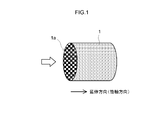
- FIG. 1 is a perspective view schematically showing a base material of an exhaust gas purifying catalyst according to an embodiment.
- FIG. 2 is a cross-sectional view schematically showing an end portion of the honeycomb substrate of FIG.
- FIG. 3 is an enlarged cross-sectional view schematically showing a configuration in the vicinity of the partition wall of the exhaust gas purifying catalyst according to one embodiment.
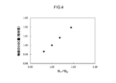
- FIG. 4 is a graph showing the relationship between the amount of OSC of the exhaust gas purifying catalyst and D 1 / D 2 when the coating density of the second catalyst layer is changed.
- FIG. 5 is a graph showing the relationship between the rate of increase in pressure loss and D 1 / D 2 when the coating density of the second catalyst layer is changed.
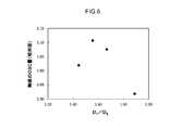
- FIG. 6 is a graph showing the relationship between the amount of OSC of the exhaust gas purifying catalyst and D 1 / D 2 when the coating density of the first catalyst layer is changed.
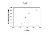
- FIG. 7 is a graph showing the relationship between the rate of increase in pressure loss and D 1 / D 2 when the coating density of the first catalyst layer is changed.
- a and B the difference between A and B is It means about ⁇ 10%, typically about ⁇ 5%, preferably about ⁇ 2%.
- a to B (A and B are arbitrary values)” includes values of A and B (upper limit value and lower limit value) unless otherwise specified.
- the exhaust gas-purifying catalyst disclosed herein is a so-called wall flow type, and includes a base material having a wall flow structure and two catalyst layers (a first catalyst layer and a second catalyst layer).
- a base material having a wall flow structure and two catalyst layers (a first catalyst layer and a second catalyst layer).
- two catalyst layers and at least one substrate exposed portion are provided in a predetermined arrangement inside the partition wall of the base material, and both of the two catalyst layers are oxygen.
- the effect peculiar to the present invention is that the material contains an occlusion material and the ratio (D 1 / D 2 ) of the coating density D 1 of the first catalyst layer to the coating density D 2 of the second catalyst layer satisfies a predetermined range.
- other configurations are not particularly limited, and can be arbitrarily determined in light of various standards.
- FIG. 1 is a perspective view schematically showing a base material 1 of an exhaust gas purifying catalyst 10 according to an embodiment.
- a honeycomb base material (honeycomb structure) 1 having a cylindrical outer shape is employed.
- the external shape of the whole honeycomb base material 1 can also be made into an elliptical cylinder shape, a polygonal cylinder shape etc. instead of the cylindrical shape shown in FIG.
- the honeycomb substrate 1 has partition walls formed along the extending direction (cylindrical cylinder axis direction) of the honeycomb substrate 1, and a plurality of cells partitioned by the partition walls and regularly arranged. is doing.
- FIG. 2 is a cross-sectional view schematically showing an end 1a of the honeycomb substrate 1 of FIG.
- the end 1a is circular.
- a porous partition wall 6 is disposed between adjacent cells.
- the sealing portion 2 and the opening 4 are arranged in a so-called checkered pattern.
- the material for the honeycomb substrate 1 various materials conventionally used for this kind of application can be adopted.
- the internal combustion engine is operated under a high load condition, it is made of a material having stable properties even when exposed to high temperature (for example, 400 ° C. or higher) exhaust gas.
- cordierite, aluminum titanate, ceramics such as silicon carbide (SiC), or alloys such as stainless steel can be cited.
- the capacity (total volume of the cells) of the honeycomb substrate 1 is usually 0.1 L or more, preferably 0.5 L or more, for example, 5 L or less, preferably 3 L or less, more preferably 2 L or less.
- the total length of the honeycomb substrate 1 in the cylinder axis direction is usually about 10 to 500 mm, for example, about 50 to 300 mm.
- FIG. 3 is an enlarged cross-sectional view schematically showing a configuration in the vicinity of the partition wall 26 of the exhaust gas purifying catalyst 10 according to an embodiment.
- the base material of the exhaust gas purifying catalyst 10 shown in FIG. 3 has an opening 4 at the end portion 24a on the exhaust gas inflow side (in the U shape) and an opening portion at the end portion 25a on the exhaust gas outflow side. 4 and a delivery cell 25 having a U-shape (a U-shape) is partitioned by a porous partition wall 26. Sealing portions 22 are provided at the end of the inlet cell 24 on the exhaust gas outflow side and the end of the outlet cell 25 on the exhaust gas inflow side, thereby being sealed.
- the inlet side cell 24 and the outlet side cell 25 may be set to appropriate shapes and sizes in consideration of, for example, the flow rate and components of the exhaust gas supplied to the exhaust gas purification catalyst 10. Further, the shapes of the entry side cell 24 and the exit side cell 25 are not particularly limited. For example, a rectangle such as a square, a parallelogram, a rectangle, and a trapezoid, a triangle, and other polygons (for example, a hexagon, an octagon), Various geometric shapes such as a circle can be used.
- the partition wall 26 has a porous structure through which exhaust gas can pass.
- the total thickness of the partition wall 26 (in other words, the length in the direction orthogonal to the extending direction of the partition wall 6) Tw is a viewpoint of improving exhaust gas purification performance, a viewpoint of improving mechanical strength, a viewpoint of suppressing an increase in pressure loss, and the like. Therefore, for example, it may be about 0.05 to 2 mm.
- the porosity of the partition walls 26 is usually about 40 to 70% from the viewpoint of improving the mechanical strength and suppressing the increase in pressure loss.
- the average pore diameter of the partition walls 26 is usually about 10 to 40 ⁇ m from the viewpoint of improving the PM collection performance and suppressing the increase in pressure loss.
- the exhaust gas-purifying catalyst 10 disclosed herein has predetermined properties (for example, length, thickness, coat density, OSC material density) inside the partition wall 26 (specifically, the surface in the pores of the partition wall 26). ), That is, a first catalyst layer 261 and a second catalyst layer 262.
- the exhaust gas discharged from the internal combustion engine flows into the inlet cell 24 from the end 24 a on the exhaust gas inflow side.
- the exhaust gas that has flowed into the inlet cell 24 passes through the pores of the porous partition wall 26 and flows out from the exhaust gas outlet end 25a of the outlet cell 25, as indicated by the arrows in FIG.
- the exhaust gas contacts the catalyst layer (the first catalyst layer 261 and / or the second catalyst layer 262) while passing through the partition wall 26. As a result, harmful components in the exhaust gas are purified (detoxified).
- HC components and CO components contained in the exhaust gas are oxidized by the catalytic function of the catalyst layer and converted (purified) into water (H 2 O), carbon dioxide (CO 2 ), and the like. Further, the NO x component is reduced by the catalytic function of the catalyst layer and converted (purified) into nitrogen (N 2 ). Since the PM component is difficult to pass through the pores of the partition walls 26, the PM component is generally deposited on the partition walls 26 in the entry side cell 24 (for example, at a position near the sealing portion 22 on the partition walls 26). The deposited PM is self-combusted by the catalytic function of the first catalyst layer 261, or is forcibly burned at a predetermined temperature (for example, about 500 to 700 ° C.) and decomposed.
- a predetermined temperature for example, about 500 to 700 ° C.
- the straight type exhaust gas purification catalyst In addition, there is a so-called straight type as a structure contrasted with the wall flow type.
- the straight type exhaust gas purifying catalyst the catalyst layer and the exhaust gas react in order from the front stage (upstream side) to the rear stage (downstream side) of the base material, and harmful components are purified.
- the type of catalytic metal, the arrangement of the catalyst layer (the laminated structure in the length and thickness direction, etc.), etc. are determined in consideration of the order of the purification reaction.
- the arrangement and properties of the catalyst layer are determined for the purpose of controlling the flow of exhaust gas in the catalyst (particularly in the partition walls). In this respect, the wall flow type and the straight type are technically different.
- Both the first catalyst layer 261 and the second catalyst layer 262 are provided inside the partition wall 26 of the exhaust gas purifying catalyst 10.
- the two catalyst layers form the main body of the exhaust gas purifying catalyst 10 as a place for purifying the exhaust gas.
- each of the two catalyst layers includes a catalyst metal that functions as an oxidation and / or reduction catalyst, a carrier that supports the catalyst metal, and an oxygen storage material (OSC material).
- OSC material oxygen storage material
- the carrier and the OSC material may be the same. That is, the carrier supporting the catalyst metal may function as the OSC material.
- the catalyst metal one or more of various metal species known to be capable of functioning as an oxidation catalyst or a reduction catalyst can be appropriately employed.
- noble metals such as rhodium (Rh), palladium (Pd), and platinum (Pt), which are platinum groups, can be used.
- An alloy with these metals can also be used.
- Such a catalyst metal is preferably used as fine particles having a sufficiently small particle diameter from the viewpoint of increasing the contact area with the exhaust gas.
- the average particle size of the catalyst metal particles (average value of particle sizes determined by TEM observation; the same shall apply hereinafter) is usually about 1 to 15 nm, preferably 10 nm or less, 7 nm or less, and more preferably 5 nm or less. Note that the types of catalyst metals contained in the two catalyst layers (the first catalyst layer 261 and the second catalyst layer 262) may be the same or different.
- the first catalyst layer 261 includes rhodium (Rh).
- Rh rhodium
- a purification reaction can be actively generated on the upstream side (first catalyst layer 261) of the exhaust gas.
- reaction heat during the purification reaction can be transmitted to the downstream side of the exhaust gas (second catalyst layer 262), and the temperature of the entire catalyst can be kept high (kept warm). Therefore, the purification performance (particularly NO x purification performance) can be effectively enhanced within a limited amount of catalytic metal.
- one catalyst layer for example, the first catalyst layer 261 has a high reduction activity (for example, rhodium), and the other catalyst layer (for example, the second catalyst layer 262) has a high oxidation activity.
- a metal species for example, palladium (Pd) is provided. According to such a configuration, harmful components in the exhaust gas can be efficiently purified at once.
- the supporting rate of the catalyst metal in each catalyst layer is not particularly limited. For example, it may be determined in consideration of the length and thickness of the two catalyst layers 261 and 262, the flow rate of exhaust gas to be supplied, and the like.
- the loading ratio in each catalyst layer is 0.05 to 1.5% by mass, preferably 0.1 to 1.5% by mass, and more preferably 0.2 to 1% by mass.
- the loading ratio is a predetermined value or more, excellent catalytic activity can be better realized.
- the loading ratio is not more than a predetermined value, metal grain growth (sintering) can be highly suppressed, and high durability can be realized. Furthermore, it is advantageous in terms of cost.
- the application of the present invention is particularly effective when the catalyst metal loading is low.
- the catalyst metal loading rate of the first catalyst layer 261 and the catalyst metal loading rate of the second catalyst layer 262 may be the same or different.
- the ratio of the loading ratio of the first catalyst layer 261 to the loading ratio of the second catalyst layer 262 is approximately 1 to 1.5, for example, 1 to 1.2.
- the loading rate of the first catalyst layer 261 is higher than the loading rate of the second catalyst layer 262.
- the reaction heat is efficiently transmitted to the downstream side (second catalyst layer 262) of the exhaust gas purification catalyst 10 along with the flow of the exhaust gas, thereby improving the warm-up property and the heat retaining property of the exhaust gas purification catalyst 10. can do. Therefore, for example, even if the exhaust gas temperature temporarily falls below the catalyst activation temperature (for example, an eco car in which the engine is repeatedly started and stopped during operation or during a pause such as waiting for a signal), it is excellent.
- the catalytic activity can be realized stably.
- the carrier for supporting the catalyst metal one or more inorganic materials similar to those of the conventional exhaust gas purifying catalyst can be appropriately employed.
- a porous material having a relatively large specific surface area (here, the specific surface area measured by the BET method; the same shall apply hereinafter) is preferable.
- alumina Al 2 O 3
- ceria CeO 2
- zirconia ZrO 2
- silica SiO 2
- titania TiO 2
- solid solutions thereof for example, ceria-zirconia composite oxide
- CZ complex oxide solid solutions thereof.
- alumina and CZ composite oxide are preferable.
- the specific surface area of the carrier (for example, alumina powder or CZ composite oxide powder) is preferably about 10 to 500 m 2 / g, for example, 200 to 400 m 2 / g, from the viewpoints of heat resistance and structural stability.
- the average particle size of the carrier is preferably about 1 to 500 nm, for example, 10 to 200 nm. Note that the types of carriers contained in the two catalyst layers (the first catalyst layer 261 and the second catalyst layer 262) may be the same or different.
- the oxygen storage material plays a role of stably maintaining the exhaust gas atmosphere in the exhaust gas purification catalyst 10 in the vicinity of the stoichiometric (theoretical air-fuel ratio).
- the OSC material one or more of various compounds known to have oxygen storage ability can be appropriately employed.
- the above-mentioned ceria (CeO 2 ), a composite oxide containing the ceria (for example, CZ composite oxide), and the like can be given.
- CZ composite oxide is preferable.
- grain growth is suppressed by dissolving zirconia and ceria in solid solution. For this reason, it is excellent in durability and can exhibit excellent OSC ability over a long period of time.
- the types of OSC materials included in the two catalyst layers may be the same or different.
- the OSC material is included in each of the two catalyst layers as a support on which the catalyst metal particles are supported and / or as a promoter on which the catalyst metal particles are not supported.
- the OSC materials included in the two catalyst layers may be the same or different.
- the first catalyst layer 261 and / or the second catalyst layer 262 includes an OSC material as a promoter. Thereby, the oxygen storage rate (OSC ability) to OSC material can improve, and the effect of the present invention can be exhibited at a higher level.
- OSC material content density in the first catalyst layer 261 (OSC material content per liter of substrate volume) O 1 and OSC material content density in the second catalyst layer 262 (OSC material content per liter of substrate volume) Content) O 2 may be the same or different.
- the content density O 1 of the first catalyst layer 261 is higher than the content density O 2 of the second catalyst layer 262 (that is, O 2 ⁇ O 1 ).
- the content density O 1 of the OSC material in the first catalyst layer 261, the ratio between the content density of O 2 OSC material in the second catalyst layer 262 (O 1 / O 2) is the ratio of the coating density It is equal to (D 1 / D 2 ). That is, O 1 / O 2 is generally 1.1 to 1.8, preferably 1.4 to 1.7. Thereby, the effect of improving the OSC ability is exhibited at a higher level.
- the OSC material content density O 1 in the first catalyst layer 261 is not particularly limited because it depends on the properties of the substrate (for example, the shape of the cell, the thickness of the partition walls, the porosity).
- the density O 1 of the OSC material in the first catalyst layer 261 is approximately 80 g / L or less, preferably 70 g / L or less, more preferably 50 g / L or less, for example 45 g. / L or less.
- the OSC material content density O 1 in the first catalyst layer 261 is approximately 10 g / L or more, preferably 20 g / L or more, more preferably 30 g / L. For example, it is 40 g / L or more.
- the content density O 2 of the OSC material in the second catalyst layer 262 is not particularly limited because it depends on the properties of the substrate (for example, the shape of the cell, the thickness of the partition walls, and the porosity).
- the density O 2 of the OSC material in the second catalyst layer 262 is approximately 60 g / L or less, preferably 55 g / L or less, more preferably 50 g / L or less, for example 35 g. / L or less.
- the OSC material content density O 2 in the second catalyst layer 262 is approximately 5 g / L or more, preferably 10 g / L or more, for example, 20 g / L or more. is there.
- optional components may be added to the two catalyst layers (the first catalyst layer 261 and the second catalyst layer 262).
- Such optional components can be included in each catalyst layer, for example, as an additional element constituting the carrier and / or the OSC material, or in a form independent of the carrier and / or the OSC material.
- additive components include alkali metal, alkaline earth metal (eg, barium), rare earth metal compounds and oxides.
- the ratio of the coat densities of the two catalyst layers is within a predetermined range. That is, the ratio (D 1 / D 2 ) of the coating density D 1 of the first catalyst layer 261 to the coating density D 2 of the second catalyst layer 262 is 1.1 to 1.8. In other words, the coating density D 1 of the first catalyst layer 261 is 1.1 to 1.8 times the coating density D 2 of the second catalyst layer 262.
- the coating densities of the first catalyst layer 261 and the second catalyst layer 262 are made different, a portion where the exhaust gas easily passes and a portion where the exhaust gas easily passes in the extending direction of the partition wall 26 are generated, and a distribution of pressure loss is generated. Thereby, the flow of the exhaust gas in the partition wall 26 can be adjusted.
- the pressure loss of the first catalyst layer 261 increases.
- the exhaust gas hardly passes through the part of the partition wall 26 where the first catalyst layer 261 is formed. Therefore, the exhaust gas that has flowed into the inlet cell 24 from the end portion 24a on the exhaust gas inflow side easily travels straight through the inlet cell 24 to a portion where the first catalyst layer 261 is not formed.
- the exhaust gas that has traveled straight through the entry-side cell 24 flows preferentially in a portion of the partition wall 26 where the first catalyst layer 261 is not formed (typically a portion where only the second catalyst layer 262 is formed), It reaches the outgoing cell 26.
- the chance (contact area) of contact between the exhaust gas and the OSC material in the first catalyst layer 261 increases. Therefore, the oxygen absorption efficiency into the OSC material can be increased, and the OSC ability of the exhaust gas purifying catalyst 10 as a whole can be effectively improved.
- 1.2 ⁇ (D 1 / D 2 ), 1.4 ⁇ (D 1 / D 2 ), for example, 1.45 ⁇ (D 1 / D 2 ) is satisfied. Thereby, the effect mentioned above can be produced at a higher level.
- the catalyst average coating density D A of the entire exhaust gas purifying catalyst 10 is 40 ⁇ 150g / L.
- the catalyst average coating density D A is 150 g / L or less, preferably 120 g / L or less, for example, is not more than 100 g / L, it is possible to better suppress the pressure loss.
- the catalyst average coating density D A is 40 g / L or more, preferably 50 g / L or more, for example, is 60 g / L or more, it is possible to better demonstrate the purification performance. Therefore, the effect of the present invention can be exhibited at a higher level.
- Coating density D 1 of the first catalyst layer 261 a substrate having properties (e.g. cell shape and the partition wall thickness, porosity) is not particularly limited because due.
- the pressure loss (in particular, surface pressure loss when exhaust gas flowing into the exhaust gas purifying catalyst 10) from the viewpoint of reducing, coating density D 1 of the first catalyst layer 261 is approximately 200 g / L or less, preferably Is 195 g / L or less, for example 190 g / L or less.
- the coating density D 1 of the first catalyst layer 261 is approximately 40 g / L from the viewpoint of improving the purification performance on the upstream side of the exhaust gas purification catalyst 10 (region of the first catalyst layer 261).
- Coating density D 2 of the second catalyst layer 262 is not particularly limited as long as it satisfies the above ratio D 1 / D 2.
- coating density D 2 of the second catalyst layer 262 is approximately 150 g / L or less, preferably 140 g / L or less, for example 130 g / L or less.
- coating density D 2 of the second catalyst layer 262 is approximately 25 g / L or more, preferably 30 g / L or more, more preferably 35 g / L or more, for example 45 g / L or more.
- the first catalyst layer 261 is formed in an area inside the partition wall 26 and in contact with the inlet side cell 24 from the end portion 24 a on the exhaust gas inflow side toward the extending direction of the partition wall 26.
- the length L 1 in the extending direction of the first catalyst layer 261 is not particularly limited as long as it is shorter than the total length L w in the extending direction of the partition walls 26 (that is, L 1 ⁇ L w ).
- L 1 By satisfying ⁇ L w, it is possible to suitably suppress the increase in pressure loss, it is possible to exhibit the effect of the present invention at a higher level. From this point of view, L 1 preferably satisfies the L 1 ⁇ 0.9L w.
- the PM component in the exhaust gas does not easily pass through the partition wall 26 and tends to be deposited in the vicinity of the end portion 25a on the exhaust gas outflow side in the inlet side cell 24.
- the first catalyst layer 261 is not formed at a position close to the exhaust gas outflow side end portion 25a in the region in the partition wall 26 and in contact with the inlet side cell 24. Thereby, the increase in pressure loss can be suppressed suitably. From this point of view, it is preferable to satisfy L 1 ⁇ 0.8 L w, and more preferably satisfies L 1 ⁇ 0.75L w.
- the first catalyst layer 261 is preferably not formed.
- an L 1 ⁇ 0.7 L w, is first catalytic layer 261 is not provided in the 30% portion of the L w from the end 25a of the exhaust gas outlet side to the stretching direction .
- the length L 1 of the first catalyst layer 261 in the extending direction satisfies 0.3 L w ⁇ L 1 .
- the opportunity for the exhaust gas and the OSC material to come into contact with each other on the upstream side of the exhaust gas purification catalyst 10 (in the region of the inlet cell 24) can be increased more suitably.
- the OSC ability can be further enhanced.
- the warm-up property of the catalyst can be improved. From this point of view, it is preferable to satisfy 0.5 L w ⁇ L 1, it is more preferable to satisfy 0.6 L w ⁇ L 1, it is particularly preferable to satisfy the 0.65L w ⁇ L 1.
- the second catalyst layer 262 is formed in the region inside the partition wall 26 and in contact with the outlet cell 25 from the end portion 25a on the exhaust gas outflow side in the extending direction of the partition wall 26.
- the length L 2 in the extending direction of the second catalyst layer 262 is not particularly limited as long as it is shorter than the total length L w in the extending direction of the partition walls 26 (that is, L 2 ⁇ L w ).
- L 2 ⁇ L w an increase in pressure loss can be suitably suppressed. From this viewpoint, it is preferable to satisfy L 2 ⁇ 0.9 L w, and it is more preferable to satisfy L 2 ⁇ 0.8 L w .
- the portion of at least 10% of L w from the end 24a of the exhaust gas inlet side toward the drawing direction is It is preferable that the second catalyst layer 262 is not formed.
- the second catalyst layer 262 is not provided in the 50% portion of the L w toward the extending direction from the end portion 24a of the exhaust gas inlet side .
- the exhaust gas can be brought into contact with the catalyst layer (the first catalyst layer 261 and / or the second catalyst layer 262) more reliably. As a result, exhaust gas can be purified more accurately, and exhaust gas emissions can be reduced to a high degree.
- the length in which the two catalyst layers (the first catalyst layer 261 and the second catalyst layer 262) overlap in the extending direction of the partition wall 26 varies depending on, for example, the thickness of each catalyst layer (the length in the direction orthogonal to the extending direction). It is not particularly limited to obtain.
- the L w , the L 1, and the L 2 satisfy the following formula: 1.1 L w ⁇ (L 1 + L 2 ) ⁇ 1.3 L w ;
- the thickness of the first catalyst layer 261 is not particularly limited for obtaining also depends for example extending direction of the length of the thickness and the first catalyst layer 261 of the partition wall 26 such.
- the first catalyst layer 261 is typically so as not to contact the contact and egress cell 25 to the entry side cell 24, it is formed shorter than the total thickness T w of the partition wall 26 (i.e., T 1 ⁇ T w ).
- the first catalyst layer 261 is preferably unevenly distributed toward the inlet cell 24 inside the partition wall 26.
- the thickness T 1 of the first catalyst layer 261 satisfies T 1 ⁇ 0.9 T w (preferably T 1 ⁇ 0.8 T w ).
- the first catalyst The layer 261 is not formed. Thereby, the pressure loss as the exhaust gas purification catalyst 10 as a whole can be effectively reduced.
- T 2 Thickness of the second catalyst layer 262 is not particularly limited for obtaining also depends for example extending direction of the length of the thickness and the second catalyst layer 262 of the partition wall 26 such .
- the second catalyst layer 262 is typically so as not to be in contact with and inlet side cell 24 in contact with the exit-side cell 25, it is formed shorter than the total thickness T w of the partition wall 26 (i.e., T 2 ⁇ T w ).
- the second catalyst layer 262 is preferably unevenly distributed toward the outlet cell 25 inside the partition wall 26.
- the thickness T 2 of the second catalyst layer 262 satisfies T 2 ⁇ 0.9 T w (preferably T 2 ⁇ 0.8 T w ). That is, in a region in contact with the inlet-side cells 24 a inside the partition wall 26, in a portion of at least 10% of the T w from the end 25a of the exhaust gas outlet side to the stretching direction (preferably 20%), the second catalyst Layer 262 is not formed. Thereby, the pressure loss as the exhaust gas purification catalyst 10 as a whole can be effectively reduced.
- a T 1 ⁇ T 2 ⁇ 0.8T w the thickness T 1 of the first catalyst layer 261, the thickness T 2 of the second catalyst layer 262 may be the same or may be different.
- T w it is preferable that the first catalyst layer 261 and the second catalyst layer 262 partially overlap in the thickness direction inside the partition wall 26.
- a T 1 + T 2 ⁇ 1.6T w thereby, exhaust gas emission can be reduced more effectively.
- the exhaust gas-purifying catalyst 10 has a first base material exposed portion at a position close to (typically in contact with) the end portion 25a on the exhaust gas outflow side in a region inside the partition wall 26 and in contact with the inlet side cell 24. with a 26N 1.
- First base material exposed portion 26N 1 is a portion where the first catalyst layer 261 and the second catalyst layer 262 is not either provided. By having the first substrate exposed portion 26N 1, it is possible to suppress the pressure loss more certainly lower.
- First base material exposed portion 26N 1 dimensions is not particularly limited. For example, it may be determined in consideration of the properties of the substrate and the intended use (for example, the expected generation amount of PM or engine output).
- the length of the first substrate exposed portion 26N 1 is, is from the end 25a of the exhaust gas outlet side 0.1 L w or more toward the stretching direction, generally less than 0.5 L w, for example, 0. 1L w to 0.3L w .
- the first substrate exposed portion 26N 1 thickness is at 0.1 T w or more from the surface in contact with the entry side cell 24, for example at 0.1 T w ⁇ 0.3 T w . With such an embodiment, the pressure loss can be further reduced while maintaining and improving the purification performance. Therefore, the effect of the present invention can be exhibited at a higher level.
- the second substrate exposed portion 26N is located in a position close to (typically in contact with) the end portion 24a on the exhaust gas inflow side in a region in the partition wall 26 that is in contact with the outlet cell 25. 2
- the dimension (length and thickness) of the second substrate exposed portion 26N2 is not particularly limited. For example, it may be determined in consideration of the properties of the substrate and the intended use (for example, the expected generation amount of PM or engine output).
- the length of the second substrate exposed portion 26N 2 is, is from the end 25a of the exhaust gas outlet side 0.1 L w or more toward the stretching direction, for example, 0.1 L w ⁇ 0.3 L w It is preferably 0.4 L w to 0.6 L w .
- the thickness of the second substrate exposed portion 26N 2 is, is from the surface in contact with the exit-side cell 25 0.1 T w or more, for example at 0.1 T w ⁇ 0.3 T w . With such an embodiment, the pressure loss can be further reduced while maintaining and improving the purification performance. Therefore, the effect of the present invention can be exhibited at a higher level.
- 1st base-material exposed part 26N1 can be provided over not only the position close to the edge part 25a by the side of exhaust gas outflow but a wider range.
- the first to the substrate exposed portion 26N 1 second and the base material exposed portion 26N 2, may be a three-dimensional first portion linked.
- Such a catalyst layer can be formed by a method similar to the conventional method.
- the two catalyst layers (the first catalyst layer 261 and the second catalyst layer 262) as shown in FIG. 3 can be formed as follows. First, a substrate as shown in FIGS. Next, two types of catalyst layer forming slurries (that is, a first catalyst layer forming slurry and a second catalyst layer forming slurry) are prepared.
- Each of the slurry for forming a catalyst layer includes a desired catalyst metal component (typically a solution containing a catalyst metal such as Pd, Pt, and Rh as ions) and a desired OSC material (typically ceria, CZ composite).
- Oxide as an essential component, and may include other optional components (for example, other carrier powders, promoters, binders, various additives, and the like).
- the properties of the slurry may be adjusted in consideration of the size of the substrate used, the porosity of the partition walls 26, the properties of the catalyst layer to be formed, and the like.
- the first catalyst layer 261 having a desired property is formed in the pores of the partition wall 26 in the portion in contact with the entry-side cell 24.
- Properties of the first catalyst layer 261 e.g., coating density D 1 and porosity
- the thickness T 1 of the first catalyst layer 261 causes the pressure difference between the inlet side cell 24 and the outlet side cell 25 by pressurizing the outlet side cell 25 at the time of supplying the slurry and when the slurry is supplied. It can be adjusted depending on the situation.
- the slurry supply, drying, and calcination operations may be the same as in the conventional catalyst layer formation.
- the second catalyst layer 262 having desired properties is formed in the pores of the partition walls 26 in contact with the outlet cells 25.
- the properties (for example, the coating density D 2 and the porosity) and the thickness T 2 of the second catalyst layer 262 are the properties of the second catalyst layer forming slurry and the supply amount of the slurry, as in the formation of the first catalyst layer 261.
- the number of times of supply, the supply time, and the pressure difference generated between the entry side cell 24 and the exit side cell 25 can be adjusted.
- the honeycomb substrate after the slurry for forming the catalyst layer is applied is dried and fired at a predetermined temperature and time.
- two catalyst layers a first catalyst layer 261 and a second catalyst layer 262 as shown in FIG. 3 can be formed.
- the method of forming two catalyst layers having different coating densities by changing the properties, supply amount, and supply frequency of two types of catalyst layer forming slurries has been introduced.
- the present invention is limited to this. is not.
- the effect of containing the OSC material is exhibited, and the amount of OSC is improved as compared with the conventional case.
- the improvement of the OSC amount and the reduction of the pressure loss can be achieved at a high level. Therefore, it can arrange
- Example 1 [I. Test example in which the coating density of the second catalyst layer was changed] ⁇ Example 1> First, as a honeycomb substrate, a cordierite wall flow type substrate (cell number: 300 cpsi (cells per square inch), volume: 0.9 L, total length: 105 mm, outer diameter: 103 mm, partition wall thickness) 0.3 mm and a porosity of the partition wall of 59%) were prepared. Next, 40 g of Al 2 O 3 powder ( ⁇ -Al 2 O 3 ) as a carrier, rhodium nitrate having a Rh content of 0.2 g, and an appropriate amount of ion-exchanged water were mixed.
- Al 2 O 3 powder ⁇ -Al 2 O 3
- the obtained mixed liquid was dried and then baked (500 ° C., 1 hour) to obtain a powder in which Rh was supported on Al 2 O 3 .
- the powder and CeO 2 —ZrO 2 composite oxide powder (promoter) having a CZ composite oxide amount after firing of 60 g were mixed with ion-exchanged water to prepare a first catalyst layer forming slurry.
- the prepared slurry for forming the first catalyst layer is supplied into the inlet cell from the end of the honeycomb substrate on the exhaust gas inflow side, and dried, so that the pores in the partition walls contacting the inlet cell are dried.
- the first catalyst layer (the length in the stretching direction L 1: 70% of the total length L w of the partition wall, the thickness T 1: 80% of the total thickness T w of the partition wall) was formed.
- gas is supplied from the end of the outlet cell on the exhaust gas outflow side to create a relative pressure difference between the inlet cell and the outlet cell, and the depth at which the slurry penetrates into the partition wall. It was adjusted.
- Example 1 the coating density D 1 of the first catalytic layer per volume 1L of the substrate was 65 g / L. Further, the OSC material content density O 1 of the first catalyst layer per 1 L of the volume of the base material was set to 36 g / L.
- a second catalyst layer forming slurry was prepared in the same manner as the first catalyst layer forming slurry except that a Pd source (palladium nitrate) was used as the catalyst metal.
- the prepared slurry for forming the second catalyst layer is supplied from the end on the exhaust gas outflow side of the honeycomb base material into the outlet cell, and dried, so that the inside of the pores in the partition wall portion in contact with the outlet cell is dried.
- a second catalyst layer (extending direction of the length L 2: 50% of the total length L w of the partition wall, the thickness T 2: 80% of the total thickness T w of the partition wall) was formed.
- Example 1 the coating density D 2 of the second catalytic layer per volume 1L of the substrate was 45 g / L. That is, the ratio of coat density (D 1 / D 2 ) was 1.44.
- the content density O 2 of the OSC material of the second catalyst layer per 1 L of the base material volume was set to 25 g / L.
- the catalyst metal loading was the same for the first catalyst layer and the second catalyst layer.
- the honeycomb base material provided with the first catalyst layer and the second catalyst layer was dried at 150 ° C. for 1 hour and then calcined at 500 ° C. for 1 hour to obtain an exhaust gas purifying catalyst (Example 1).
- an exhaust gas purifying catalyst (Example 1).
- the exhaust gas purifying catalyst of Example 1 has a first base material exposed portion in a region inside the partition wall and in contact with the entry side cell.
- the first substrate exposed portion is 30% of the length of L w in the extending direction from an end portion of the exhaust gas outflow side (0.3 L w), from the surface of the side in contact with the inlet side cell in the thickness direction of the T w 20% of the thickness (0.2T w), is provided.
- the exhaust gas purifying catalyst of Example 1 has the second base material exposed portion in the region inside the partition wall and in contact with the exit side cell.
- Second substrate exposed portion is 50% of the length of L w in the extending direction from an end portion of the exhaust gas inlet side (0.5 L w), from the surface of the side in contact with the exit-side cell in the thickness direction of the T w 20% of the thickness (0.2T w), is provided.
- Example 2 Reference Examples 1 and 2> As in Example 1 above, except that the properties (viscosity and solid content) of the slurry for forming the second catalyst layer and the number of times of supply were adjusted so that the coating density of the second catalyst layer became the value shown in Table 1 below. Exhaust gas purification catalysts (Example 2, Reference Examples 1 and 2) were prepared. The amount of catalyst metal supported on the catalyst layer was the same in all examples. The specifications of the catalyst layer are summarized in Table 1 below.
- the oxygen absorption / release capacity (OSC) of the exhaust gas purifying catalyst was evaluated. Specifically, the exhaust gas purification catalyst was attached to the exhaust pipe of the engine, and an O 2 sensor was attached downstream of the exhaust gas purification catalyst. Then, the air-fuel ratio A / F of the mixed gas supplied to the engine is periodically switched between rich and lean every predetermined time. Based on the behavior of the O 2 sensor, (1) after the catalyst has completely released oxygen. The average oxygen storage / release amount (OSC amount) was calculated from the operating conditions and time until the oxygen was fully occluded, and (2) the operating condition and time until the oxygen was fully occluded and released. The results are shown in the corresponding column of Table 1. Here, the relative value when the OSC amount of Reference Example 1 is set as a reference (1.0) is shown. FIG. 4 shows the relationship between the amount of OSC of the exhaust gas purifying catalyst and D 1 / D 2 .
- the increase rate of pressure loss of the obtained exhaust gas-purifying catalyst was measured. Specifically, first, a honeycomb base material (reference) before coating of the catalyst layer was prepared, and the pressure when air was circulated with an air volume of 6 m 3 / min was measured. Next, using the produced exhaust gas-purifying catalyst (honeycomb substrate with a catalyst layer), the pressure when air was circulated with an air volume of 6 m 3 / min was measured as in the case of the reference.
- the pressure loss increase rate (%) was calculated from the following formula: [(exhaust gas purification catalyst pressure ⁇ reference pressure) / reference pressure] ⁇ 100; The results are shown in the corresponding column of Table 1. In addition, the relative value when the pressure loss increase rate of the reference example 1 is made into a reference
- FIG. 5 shows the relationship between the rate of increase in pressure loss and D 1 / D 2 .
- the OSC amount tended to increase as the coating density ratio (D 1 / D 2 ) increased.
- the coating density ratio (D 1 / D 2 ) By setting the coating density ratio (D 1 / D 2 ) to 1.1 or more (for example, 1.18 or more), the effect of the OSC material was better exhibited.
- the pressure loss tended to decrease as the ratio of the coat density (D 1 / D 2 ) increased.
- the increase in pressure loss could be reduced by 10% or more. That is, by reducing the coating density D 2 (OSC material content density O 2 ) of the second catalyst layer, it was possible to achieve both high improvement in OSC performance and reduction in pressure loss.
- Example 3 Exhaust gas as in Example 1 above, except that the properties (viscosity and solid content) of the slurry for forming the first catalyst layer and the number of times of supply were adjusted so that the coating density of the first catalyst layer would be the value shown in Table 2 below.
- a purification catalyst (Examples 3 and 4, Reference Example 3) was prepared. The amount of catalyst metal supported on the catalyst layer was the same in all examples. The specifications of the catalyst layer are summarized in Table 2 below. And the above I.D. Similarly, the OSC ability and pressure loss of the exhaust gas purifying catalyst were evaluated. The results are shown in the corresponding column of Table 2.
- FIG. 6 shows the relationship between the amount of OSC of the exhaust gas purifying catalyst and D 1 / D 2 .
- FIG. 7 shows the relationship between the rate of increase in pressure loss and D 1 / D 2 .
- the coating density ratio (D 1 / D 2 ) is around 1.5.
- the OSC amount increased, but after that, the OSC amount decreased. That is, the OSC amount was the largest when the ratio of the coat density (D 1 / D 2 ) was around 1.5.
- the reason why the OSC amount decreases when the coating density D 1 (OSC material content density O 1 ) of the first catalyst layer is equal to or higher than a predetermined amount is that the pressure loss of the first catalyst layer increases and the first catalyst layer in the partition wall has the first loss. It is conceivable that the exhaust gas hardly flows through the portion where the catalyst layer is formed. That is, it is considered that the flow rate of the exhaust gas passing through the partition wall is increased and the exhaust gas has passed through the catalyst layer quickly. Further, as apparent from Table 1 and FIG. 7, the pressure loss tended to increase (deteriorate) as the coating density ratio (D 1 / D 2 ) increased.
- the OSC amount was improved as the OSC material density O 1 of the first catalyst layer increased.
- the pressure loss was reduced as the content density O 1 of the OSC material of the first catalyst layer increased.
- the reason is considered that the bulk density of alumina is higher than that of the CZ composite oxide. That is, it can be considered that the pressure loss is reduced by reducing the content of alumina having a high bulk density, thereby expanding the flow path of the exhaust gas.
Landscapes
- Chemical & Material Sciences (AREA)
- Engineering & Computer Science (AREA)
- Chemical Kinetics & Catalysis (AREA)
- Combustion & Propulsion (AREA)
- Mechanical Engineering (AREA)
- General Engineering & Computer Science (AREA)
- Materials Engineering (AREA)
- Organic Chemistry (AREA)
- Health & Medical Sciences (AREA)
- Biomedical Technology (AREA)
- Analytical Chemistry (AREA)
- General Chemical & Material Sciences (AREA)
- Oil, Petroleum & Natural Gas (AREA)
- Environmental & Geological Engineering (AREA)
- Emergency Medicine (AREA)
- Catalysts (AREA)
- Exhaust Gas Treatment By Means Of Catalyst (AREA)
- Exhaust Gas After Treatment (AREA)
- Processes For Solid Components From Exhaust (AREA)
Abstract
L'invention concerne un catalyseur de purification de gaz d'échappement grâce auquel une capacité de stockage d'oxygène (OSC) suffisante d'un matériau d'occlusion d'oxygène est présentée et la hauteur de l'OSC est améliorée. Selon la présente invention, le catalyseur de purification de gaz d'échappement (10) est pourvu de : un substrat de type à écoulement sur paroi ; des premières couches de catalyseur (261) ; et des secondes couches de catalyseur (262). Les premières couches de catalyseur (261) sont disposées à l'intérieur de parois de séparation (26) et dans des zones en contact avec des alvéoles du côté entrée (24). Les secondes couches de catalyseur (262) sont disposées à l'intérieur des parois de séparation (26) et dans des zones en contact avec des alvéoles du côté sortie (25). Les premières couches de catalyseur (261) et les secondes couches de catalyseur (262) comprennent un matériau d'occlusion d'oxygène. Le rapport (D1/D2) de la densité de revêtement D1 des premières couches de catalyseur (261) à la densité de revêtement D2 des secondes couches de catalyseur (262) est de 1,1 à 1,8.
Priority Applications (3)
| Application Number | Priority Date | Filing Date | Title |
|---|---|---|---|
| EP16752471.9A EP3254757B1 (fr) | 2015-02-17 | 2016-02-16 | Catalyseur de purification de gaz d'échappement |
| CN201680010687.4A CN107249737B (zh) | 2015-02-17 | 2016-02-16 | 排气净化用催化剂 |
| US15/550,078 US10076725B2 (en) | 2015-02-17 | 2016-02-16 | Exhaust gas purification catalyst |
Applications Claiming Priority (2)
| Application Number | Priority Date | Filing Date | Title |
|---|---|---|---|
| JP2015028795A JP6472677B2 (ja) | 2015-02-17 | 2015-02-17 | 排ガス浄化用触媒 |
| JP2015-028795 | 2015-02-17 |
Publications (1)
| Publication Number | Publication Date |
|---|---|
| WO2016133085A1 true WO2016133085A1 (fr) | 2016-08-25 |
Family
ID=56688874
Family Applications (1)
| Application Number | Title | Priority Date | Filing Date |
|---|---|---|---|
| PCT/JP2016/054432 WO2016133085A1 (fr) | 2015-02-17 | 2016-02-16 | Catalyseur de purification de gaz d'échappement |
Country Status (5)
| Country | Link |
|---|---|
| US (1) | US10076725B2 (fr) |
| EP (1) | EP3254757B1 (fr) |
| JP (1) | JP6472677B2 (fr) |
| CN (1) | CN107249737B (fr) |
| WO (1) | WO2016133085A1 (fr) |
Cited By (7)
| Publication number | Priority date | Publication date | Assignee | Title |
|---|---|---|---|---|
| WO2018056246A1 (fr) * | 2016-09-26 | 2018-03-29 | 株式会社キャタラー | Catalyseur de purification de gaz d'échappement |
| JP6487982B1 (ja) * | 2017-09-28 | 2019-03-20 | 株式会社キャタラー | 排ガス浄化用触媒 |
| WO2020200398A1 (fr) | 2019-03-29 | 2020-10-08 | Umicore Ag & Co. Kg | Filtre à particules à activité catalytique |
| WO2021145326A1 (fr) * | 2020-01-14 | 2021-07-22 | 三井金属鉱業株式会社 | Système de purification de gaz d'échappement |
| US11623179B2 (en) | 2017-12-19 | 2023-04-11 | Umicore Ag & Co. Kg | Catalytically active particulate filter |
| US11628400B2 (en) | 2017-12-19 | 2023-04-18 | Umicore Ag & Co. Kg | Catalytically active particulate filter |
| US11702971B2 (en) | 2017-12-19 | 2023-07-18 | Umicore Ag & Co. Kg | Catalytically active particulate filter |
Families Citing this family (15)
| Publication number | Priority date | Publication date | Assignee | Title |
|---|---|---|---|---|
| JP6916624B2 (ja) * | 2017-02-02 | 2021-08-11 | 株式会社キャタラー | 排ガス浄化装置および排ガス浄化用触媒 |
| EP3636340B1 (fr) | 2017-07-11 | 2023-08-23 | Cataler Corporation | Catalyseur pour la purification des gaz d'échappement |
| CN111295244B (zh) * | 2017-10-19 | 2023-09-05 | 株式会社科特拉 | 排气净化用催化剂 |
| WO2019109998A1 (fr) * | 2017-12-08 | 2019-06-13 | 庄信万丰(上海)化工有限公司 | Nouveau catalyseur à twc, à deux couches et à trois zones dans des applications de gaz d'échappement d'essence |
| CN111770794B (zh) * | 2018-03-30 | 2021-08-13 | 三井金属矿业株式会社 | 废气净化催化剂 |
| US11266982B2 (en) * | 2018-03-30 | 2022-03-08 | Mitsui Mining & Smelting Co., Ltd. | Exhaust gas purification catalyst |
| JPWO2019221212A1 (ja) * | 2018-05-17 | 2021-04-08 | エヌ・イーケムキャット株式会社 | 排ガス浄化触媒及びその製造方法 |
| JP2020168613A (ja) * | 2019-04-04 | 2020-10-15 | トヨタ自動車株式会社 | フィルタ触媒、排ガス浄化装置、及びフィルタ触媒の製造方法 |
| JP7211893B2 (ja) * | 2019-05-24 | 2023-01-24 | トヨタ自動車株式会社 | 排ガス浄化装置 |
| JP7386626B2 (ja) * | 2019-06-18 | 2023-11-27 | 株式会社キャタラー | パティキュレートフィルタ |
| JP2021023853A (ja) * | 2019-08-01 | 2021-02-22 | トヨタ自動車株式会社 | 排ガス浄化装置及び排ガス浄化システム並びに排ガス浄化装置の製造方法 |
| JP7386651B2 (ja) * | 2019-09-02 | 2023-11-27 | 株式会社キャタラー | 排ガス浄化用触媒 |
| WO2021125256A1 (fr) * | 2019-12-18 | 2021-06-24 | 三井金属鉱業株式会社 | Catalyseur de purification de gaz d'échappement |
| JP7381372B2 (ja) | 2020-03-12 | 2023-11-15 | トヨタ自動車株式会社 | 排ガス浄化装置 |
| WO2023047933A1 (fr) | 2021-09-22 | 2023-03-30 | 三井金属鉱業株式会社 | Catalyseur d'épuration de gaz d'échappement |
Citations (3)
| Publication number | Priority date | Publication date | Assignee | Title |
|---|---|---|---|---|
| JP2005500147A (ja) * | 1999-08-13 | 2005-01-06 | ジョンソン、マッセイ、パブリック、リミテッド、カンパニー | 触媒ウォールフローフィルタ |
| JP2010269205A (ja) * | 2009-05-19 | 2010-12-02 | Toyota Motor Corp | 排ガス浄化用触媒 |
| JP2013099748A (ja) * | 2004-09-14 | 2013-05-23 | Basf Catalysts Llc | 圧力平衡化された触媒付き排気物品 |
Family Cites Families (21)
| Publication number | Priority date | Publication date | Assignee | Title |
|---|---|---|---|---|
| DE102005005663A1 (de) * | 2005-02-08 | 2006-08-17 | Daimlerchrysler Ag | Abgasnachbehandlungseinrichtung mit Partikelfilter |
| JP2007185571A (ja) | 2006-01-11 | 2007-07-26 | Toyota Central Res & Dev Lab Inc | 排ガス浄化用触媒及びその製造方法 |
| DE102007046158B4 (de) | 2007-09-27 | 2014-02-13 | Umicore Ag & Co. Kg | Verwendung eines katalytisch aktiven Partikelfilters zur Entfernung von Partikeln aus dem Abgas von mit überwiegend stöchiometrischem Luft/Kraftstoff-Gemisch betriebenen Verbrennungsmotoren |
| GB0812544D0 (en) * | 2008-07-09 | 2008-08-13 | Johnson Matthey Plc | Exhaust system for a lean burn IC engine |
| JP2010227799A (ja) | 2009-03-26 | 2010-10-14 | Cataler Corp | 排ガス浄化用触媒 |
| DE102009033635B4 (de) | 2009-07-17 | 2020-11-05 | Umicore Ag & Co. Kg | Katalytisch aktives Partikelfilter mit Schwefelwasserstoff-Sperrfunktion, seine Verwendung und Verfahren zur Entfernung von Stickoxiden und Partikeln |
| US8758695B2 (en) * | 2009-08-05 | 2014-06-24 | Basf Se | Treatment system for gasoline engine exhaust gas |
| WO2011045847A1 (fr) | 2009-10-13 | 2011-04-21 | 日産ディーゼル工業株式会社 | Dispositif de purification d'échappement pour moteur |
| JP2011147901A (ja) * | 2010-01-22 | 2011-08-04 | Toyota Motor Corp | 排ガス浄化用触媒 |
| JP5548470B2 (ja) | 2010-02-16 | 2014-07-16 | 日本碍子株式会社 | ハニカム触媒体 |
| WO2011125771A1 (fr) | 2010-03-31 | 2011-10-13 | 日本碍子株式会社 | Filtre en nid d'abeilles et méthode de fabrication d'un filtre en nid d'abeilles |
| US8557204B2 (en) * | 2010-11-22 | 2013-10-15 | Umicore Ag & Co. Kg | Three-way catalyst having an upstream single-layer catalyst |
| US8323599B2 (en) | 2010-11-22 | 2012-12-04 | Umicore Ag & Co. Kg | Three-way catalyst having an upstream multi-layer catalyst |
| DE102010055147A1 (de) * | 2010-12-18 | 2012-06-21 | Volkswagen Ag | Vier-Wege-Katalysator, seine Verwendung sowie Fahrzeug mit einem solchen |
| US8722000B2 (en) * | 2011-03-29 | 2014-05-13 | Basf Corporation | Multi-component filters for emissions control |
| GB201207313D0 (en) * | 2012-04-24 | 2012-06-13 | Johnson Matthey Plc | Filter substrate comprising three-way catalyst |
| GB2513364B (en) * | 2013-04-24 | 2019-06-19 | Johnson Matthey Plc | Positive ignition engine and exhaust system comprising catalysed zone-coated filter substrate |
| KR102068969B1 (ko) * | 2012-06-06 | 2020-01-22 | 우미코레 아게 운트 코 카게 | 가솔린 미립자 필터의 업스트림에 사용하기 위한 시동 촉매 |
| JP2014001679A (ja) | 2012-06-18 | 2014-01-09 | Toyota Motor Corp | 触媒コンバーター |
| GB2512648B (en) | 2013-04-05 | 2018-06-20 | Johnson Matthey Plc | Filter substrate comprising three-way catalyst |
| GB2520776A (en) * | 2013-12-02 | 2015-06-03 | Johnson Matthey Plc | Wall-flow filter comprising catalytic washcoat |
-
2015
- 2015-02-17 JP JP2015028795A patent/JP6472677B2/ja active Active
-
2016
- 2016-02-16 CN CN201680010687.4A patent/CN107249737B/zh active Active
- 2016-02-16 EP EP16752471.9A patent/EP3254757B1/fr active Active
- 2016-02-16 WO PCT/JP2016/054432 patent/WO2016133085A1/fr active Application Filing
- 2016-02-16 US US15/550,078 patent/US10076725B2/en active Active
Patent Citations (3)
| Publication number | Priority date | Publication date | Assignee | Title |
|---|---|---|---|---|
| JP2005500147A (ja) * | 1999-08-13 | 2005-01-06 | ジョンソン、マッセイ、パブリック、リミテッド、カンパニー | 触媒ウォールフローフィルタ |
| JP2013099748A (ja) * | 2004-09-14 | 2013-05-23 | Basf Catalysts Llc | 圧力平衡化された触媒付き排気物品 |
| JP2010269205A (ja) * | 2009-05-19 | 2010-12-02 | Toyota Motor Corp | 排ガス浄化用触媒 |
Cited By (15)
| Publication number | Priority date | Publication date | Assignee | Title |
|---|---|---|---|---|
| AU2017332907B2 (en) * | 2016-09-26 | 2020-07-16 | Cataler Corporation | Exhaust gas purifying catalyst |
| JP2018051442A (ja) * | 2016-09-26 | 2018-04-05 | 株式会社キャタラー | 排ガス浄化用触媒 |
| WO2018056246A1 (fr) * | 2016-09-26 | 2018-03-29 | 株式会社キャタラー | Catalyseur de purification de gaz d'échappement |
| US10814311B2 (en) | 2016-09-26 | 2020-10-27 | Cataler Corporation | Exhaust gas purifying catalyst |
| US11187129B2 (en) | 2017-09-28 | 2021-11-30 | Cataler Corporation | Exhaust gas purification catalyst |
| JP2019063700A (ja) * | 2017-09-28 | 2019-04-25 | 株式会社キャタラー | 排ガス浄化用触媒 |
| WO2019065206A1 (fr) * | 2017-09-28 | 2019-04-04 | 株式会社キャタラー | Catalyseur de purification de gaz d'échappement |
| JP6487982B1 (ja) * | 2017-09-28 | 2019-03-20 | 株式会社キャタラー | 排ガス浄化用触媒 |
| US11623179B2 (en) | 2017-12-19 | 2023-04-11 | Umicore Ag & Co. Kg | Catalytically active particulate filter |
| US11628400B2 (en) | 2017-12-19 | 2023-04-18 | Umicore Ag & Co. Kg | Catalytically active particulate filter |
| US11702971B2 (en) | 2017-12-19 | 2023-07-18 | Umicore Ag & Co. Kg | Catalytically active particulate filter |
| WO2020200398A1 (fr) | 2019-03-29 | 2020-10-08 | Umicore Ag & Co. Kg | Filtre à particules à activité catalytique |
| EP4029592A1 (fr) | 2019-03-29 | 2022-07-20 | UMICORE AG & Co. KG | Filtre à particules à activité catalytique |
| WO2021145326A1 (fr) * | 2020-01-14 | 2021-07-22 | 三井金属鉱業株式会社 | Système de purification de gaz d'échappement |
| JP7436522B2 (ja) | 2020-01-14 | 2024-02-21 | 三井金属鉱業株式会社 | 排ガス浄化システム |
Also Published As
| Publication number | Publication date |
|---|---|
| US20180021726A1 (en) | 2018-01-25 |
| EP3254757A1 (fr) | 2017-12-13 |
| EP3254757B1 (fr) | 2019-01-30 |
| CN107249737B (zh) | 2020-10-20 |
| CN107249737A (zh) | 2017-10-13 |
| US10076725B2 (en) | 2018-09-18 |
| EP3254757A4 (fr) | 2018-01-10 |
| JP6472677B2 (ja) | 2019-02-20 |
| JP2016150305A (ja) | 2016-08-22 |
Similar Documents
| Publication | Publication Date | Title |
|---|---|---|
| WO2016133085A1 (fr) | Catalyseur de purification de gaz d'échappement | |
| JP6527935B2 (ja) | 排ガス浄化用触媒 | |
| JP6655060B2 (ja) | 排ガス浄化用触媒 | |
| JP6353918B2 (ja) | 排ガス浄化用触媒 | |
| JP6381663B2 (ja) | 排ガス浄化用触媒 | |
| JP6353919B2 (ja) | 排ガス浄化用触媒 | |
| KR102536415B1 (ko) | 층상 자동차 촉매 복합체 | |
| JP6611611B2 (ja) | 排ガス浄化用触媒 | |
| CN108883396B (zh) | 废气净化用催化剂 | |
| US10376839B2 (en) | Exhaust gas purification catalyst for lean burn engine | |
| JP6539666B2 (ja) | 排ガス浄化用触媒 | |
| CN111295244B (zh) | 排气净化用催化剂 | |
| WO2019065206A1 (fr) | Catalyseur de purification de gaz d'échappement | |
| JP6748590B2 (ja) | 排ガス浄化用触媒 | |
| CN112808279A (zh) | 排气净化用催化剂 | |
| EP3932550A1 (fr) | Catalyseur pour purifier un gaz d'échappement | |
| JP6175275B2 (ja) | 排ガス浄化用触媒 | |
| CN111790270A (zh) | 过滤器催化剂、废气净化装置和过滤器催化剂的制造方法 | |
| JP2019081160A (ja) | 排ガス浄化用触媒 |
Legal Events
| Date | Code | Title | Description |
|---|---|---|---|
| 121 | Ep: the epo has been informed by wipo that ep was designated in this application |
Ref document number: 16752471 Country of ref document: EP Kind code of ref document: A1 |
|
| WWE | Wipo information: entry into national phase |
Ref document number: 15550078 Country of ref document: US |
|
| NENP | Non-entry into the national phase |
Ref country code: DE |
|
| REEP | Request for entry into the european phase |
Ref document number: 2016752471 Country of ref document: EP |