EP3689457B1 - Catalyseur de purification de gaz d'échappement - Google Patents
Catalyseur de purification de gaz d'échappement Download PDFInfo
- Publication number
- EP3689457B1 EP3689457B1 EP18860962.2A EP18860962A EP3689457B1 EP 3689457 B1 EP3689457 B1 EP 3689457B1 EP 18860962 A EP18860962 A EP 18860962A EP 3689457 B1 EP3689457 B1 EP 3689457B1
- Authority
- EP
- European Patent Office
- Prior art keywords
- catalyst
- partition wall
- catalyst layer
- exhaust gas
- contact
- Prior art date
- Legal status (The legal status is an assumption and is not a legal conclusion. Google has not performed a legal analysis and makes no representation as to the accuracy of the status listed.)
- Active
Links
- 239000003054 catalyst Substances 0.000 title claims description 376
- 238000005192 partition Methods 0.000 claims description 170
- 238000000746 purification Methods 0.000 claims description 96
- 230000009467 reduction Effects 0.000 claims description 39
- 230000003647 oxidation Effects 0.000 claims description 36
- 238000007254 oxidation reaction Methods 0.000 claims description 36
- 238000002485 combustion reaction Methods 0.000 claims description 26
- 239000003502 gasoline Substances 0.000 claims description 7
- 230000007423 decrease Effects 0.000 claims description 4
- 239000007789 gas Substances 0.000 description 136
- MWUXSHHQAYIFBG-UHFFFAOYSA-N nitrogen oxide Inorganic materials O=[N] MWUXSHHQAYIFBG-UHFFFAOYSA-N 0.000 description 54
- 230000000052 comparative effect Effects 0.000 description 39
- 239000002002 slurry Substances 0.000 description 29
- KDLHZDBZIXYQEI-UHFFFAOYSA-N palladium Substances [Pd] KDLHZDBZIXYQEI-UHFFFAOYSA-N 0.000 description 28
- 229910052751 metal Inorganic materials 0.000 description 27
- 239000002184 metal Substances 0.000 description 27
- 239000010948 rhodium Substances 0.000 description 26
- 229930195733 hydrocarbon Natural products 0.000 description 16
- 150000002430 hydrocarbons Chemical class 0.000 description 16
- 239000011248 coating agent Substances 0.000 description 15
- 238000000576 coating method Methods 0.000 description 15
- 229910052763 palladium Inorganic materials 0.000 description 12
- 238000011144 upstream manufacturing Methods 0.000 description 11
- 239000013618 particulate matter Substances 0.000 description 10
- BASFCYQUMIYNBI-UHFFFAOYSA-N platinum Chemical compound [Pt] BASFCYQUMIYNBI-UHFFFAOYSA-N 0.000 description 10
- 229910052703 rhodium Inorganic materials 0.000 description 9
- 238000000034 method Methods 0.000 description 8
- 238000012360 testing method Methods 0.000 description 8
- 238000001035 drying Methods 0.000 description 7
- 238000010304 firing Methods 0.000 description 7
- UGFAIRIUMAVXCW-UHFFFAOYSA-N Carbon monoxide Chemical compound [O+]#[C-] UGFAIRIUMAVXCW-UHFFFAOYSA-N 0.000 description 6
- PNEYBMLMFCGWSK-UHFFFAOYSA-N aluminium oxide Inorganic materials [O-2].[O-2].[O-2].[Al+3].[Al+3] PNEYBMLMFCGWSK-UHFFFAOYSA-N 0.000 description 6
- 229910002091 carbon monoxide Inorganic materials 0.000 description 6
- 229910000422 cerium(IV) oxide Inorganic materials 0.000 description 6
- 238000006243 chemical reaction Methods 0.000 description 6
- 229910052878 cordierite Inorganic materials 0.000 description 6
- 238000010586 diagram Methods 0.000 description 6
- JSKIRARMQDRGJZ-UHFFFAOYSA-N dimagnesium dioxido-bis[(1-oxido-3-oxo-2,4,6,8,9-pentaoxa-1,3-disila-5,7-dialuminabicyclo[3.3.1]nonan-7-yl)oxy]silane Chemical compound [Mg++].[Mg++].[O-][Si]([O-])(O[Al]1O[Al]2O[Si](=O)O[Si]([O-])(O1)O2)O[Al]1O[Al]2O[Si](=O)O[Si]([O-])(O1)O2 JSKIRARMQDRGJZ-UHFFFAOYSA-N 0.000 description 6
- 239000011148 porous material Substances 0.000 description 6
- 239000000843 powder Substances 0.000 description 6
- 230000015572 biosynthetic process Effects 0.000 description 5
- 239000000463 material Substances 0.000 description 5
- 229910052697 platinum Inorganic materials 0.000 description 5
- 239000000243 solution Substances 0.000 description 5
- GWEVSGVZZGPLCZ-UHFFFAOYSA-N Titan oxide Chemical compound O=[Ti]=O GWEVSGVZZGPLCZ-UHFFFAOYSA-N 0.000 description 4
- MCMNRKCIXSYSNV-UHFFFAOYSA-N Zirconium dioxide Chemical compound O=[Zr]=O MCMNRKCIXSYSNV-UHFFFAOYSA-N 0.000 description 4
- QVGXLLKOCUKJST-UHFFFAOYSA-N atomic oxygen Chemical compound [O] QVGXLLKOCUKJST-UHFFFAOYSA-N 0.000 description 4
- CETPSERCERDGAM-UHFFFAOYSA-N ceric oxide Chemical compound O=[Ce]=O CETPSERCERDGAM-UHFFFAOYSA-N 0.000 description 4
- 239000000446 fuel Substances 0.000 description 4
- 239000001301 oxygen Substances 0.000 description 4
- 229910052760 oxygen Inorganic materials 0.000 description 4
- 238000007789 sealing Methods 0.000 description 4
- VZSRBBMJRBPUNF-UHFFFAOYSA-N 2-(2,3-dihydro-1H-inden-2-ylamino)-N-[3-oxo-3-(2,4,6,7-tetrahydrotriazolo[4,5-c]pyridin-5-yl)propyl]pyrimidine-5-carboxamide Chemical compound C1C(CC2=CC=CC=C12)NC1=NC=C(C=N1)C(=O)NCCC(N1CC2=C(CC1)NN=N2)=O VZSRBBMJRBPUNF-UHFFFAOYSA-N 0.000 description 3
- PXHVJJICTQNCMI-UHFFFAOYSA-N Nickel Chemical compound [Ni] PXHVJJICTQNCMI-UHFFFAOYSA-N 0.000 description 3
- VYPSYNLAJGMNEJ-UHFFFAOYSA-N Silicium dioxide Chemical compound O=[Si]=O VYPSYNLAJGMNEJ-UHFFFAOYSA-N 0.000 description 3
- 239000003426 co-catalyst Substances 0.000 description 3
- 230000000694 effects Effects 0.000 description 3
- 238000011156 evaluation Methods 0.000 description 3
- 239000000203 mixture Substances 0.000 description 3
- 239000003381 stabilizer Substances 0.000 description 3
- 238000003860 storage Methods 0.000 description 3
- XLYOFNOQVPJJNP-UHFFFAOYSA-N water Substances O XLYOFNOQVPJJNP-UHFFFAOYSA-N 0.000 description 3
- 229910003158 γ-Al2O3 Inorganic materials 0.000 description 3
- 229910045601 alloy Inorganic materials 0.000 description 2
- 239000000956 alloy Substances 0.000 description 2
- 238000005275 alloying Methods 0.000 description 2
- 229910052788 barium Inorganic materials 0.000 description 2
- DSAJWYNOEDNPEQ-UHFFFAOYSA-N barium atom Chemical compound [Ba] DSAJWYNOEDNPEQ-UHFFFAOYSA-N 0.000 description 2
- TZCXTZWJZNENPQ-UHFFFAOYSA-L barium sulfate Chemical compound [Ba+2].[O-]S([O-])(=O)=O TZCXTZWJZNENPQ-UHFFFAOYSA-L 0.000 description 2
- 230000033228 biological regulation Effects 0.000 description 2
- 239000011575 calcium Substances 0.000 description 2
- 230000003197 catalytic effect Effects 0.000 description 2
- 239000010949 copper Substances 0.000 description 2
- 239000010931 gold Substances 0.000 description 2
- GPNDARIEYHPYAY-UHFFFAOYSA-N palladium(ii) nitrate Chemical compound [Pd+2].[O-][N+]([O-])=O.[O-][N+]([O-])=O GPNDARIEYHPYAY-UHFFFAOYSA-N 0.000 description 2
- 230000002093 peripheral effect Effects 0.000 description 2
- MHOVAHRLVXNVSD-UHFFFAOYSA-N rhodium atom Chemical compound [Rh] MHOVAHRLVXNVSD-UHFFFAOYSA-N 0.000 description 2
- VXNYVYJABGOSBX-UHFFFAOYSA-N rhodium(3+);trinitrate Chemical compound [Rh+3].[O-][N+]([O-])=O.[O-][N+]([O-])=O.[O-][N+]([O-])=O VXNYVYJABGOSBX-UHFFFAOYSA-N 0.000 description 2
- 229910000505 Al2TiO5 Inorganic materials 0.000 description 1
- OYPRJOBELJOOCE-UHFFFAOYSA-N Calcium Chemical compound [Ca] OYPRJOBELJOOCE-UHFFFAOYSA-N 0.000 description 1
- RYGMFSIKBFXOCR-UHFFFAOYSA-N Copper Chemical compound [Cu] RYGMFSIKBFXOCR-UHFFFAOYSA-N 0.000 description 1
- XEEYBQQBJWHFJM-UHFFFAOYSA-N Iron Chemical compound [Fe] XEEYBQQBJWHFJM-UHFFFAOYSA-N 0.000 description 1
- 229910001260 Pt alloy Inorganic materials 0.000 description 1
- KJTLSVCANCCWHF-UHFFFAOYSA-N Ruthenium Chemical compound [Ru] KJTLSVCANCCWHF-UHFFFAOYSA-N 0.000 description 1
- BQCADISMDOOEFD-UHFFFAOYSA-N Silver Chemical compound [Ag] BQCADISMDOOEFD-UHFFFAOYSA-N 0.000 description 1
- 239000000654 additive Substances 0.000 description 1
- 239000003463 adsorbent Substances 0.000 description 1
- 230000004075 alteration Effects 0.000 description 1
- -1 alumina (Al2O3) Chemical class 0.000 description 1
- 229910052791 calcium Inorganic materials 0.000 description 1
- 229910052799 carbon Inorganic materials 0.000 description 1
- 239000000969 carrier Substances 0.000 description 1
- 239000000919 ceramic Substances 0.000 description 1
- 239000007809 chemical reaction catalyst Substances 0.000 description 1
- 229910017052 cobalt Inorganic materials 0.000 description 1
- 239000010941 cobalt Substances 0.000 description 1
- GUTLYIVDDKVIGB-UHFFFAOYSA-N cobalt atom Chemical compound [Co] GUTLYIVDDKVIGB-UHFFFAOYSA-N 0.000 description 1
- 238000007796 conventional method Methods 0.000 description 1
- 229910052802 copper Inorganic materials 0.000 description 1
- 238000005520 cutting process Methods 0.000 description 1
- 238000013461 design Methods 0.000 description 1
- 230000002708 enhancing effect Effects 0.000 description 1
- 239000002737 fuel gas Substances 0.000 description 1
- PCHJSUWPFVWCPO-UHFFFAOYSA-N gold Chemical compound [Au] PCHJSUWPFVWCPO-UHFFFAOYSA-N 0.000 description 1
- 229910052737 gold Inorganic materials 0.000 description 1
- 239000003779 heat-resistant material Substances 0.000 description 1
- 238000002347 injection Methods 0.000 description 1
- 239000007924 injection Substances 0.000 description 1
- 150000002500 ions Chemical class 0.000 description 1
- 229910052741 iridium Inorganic materials 0.000 description 1
- GKOZUEZYRPOHIO-UHFFFAOYSA-N iridium atom Chemical compound [Ir] GKOZUEZYRPOHIO-UHFFFAOYSA-N 0.000 description 1
- 229910052746 lanthanum Inorganic materials 0.000 description 1
- FZLIPJUXYLNCLC-UHFFFAOYSA-N lanthanum atom Chemical compound [La] FZLIPJUXYLNCLC-UHFFFAOYSA-N 0.000 description 1
- 238000004519 manufacturing process Methods 0.000 description 1
- 230000007246 mechanism Effects 0.000 description 1
- 229910044991 metal oxide Inorganic materials 0.000 description 1
- 150000004706 metal oxides Chemical class 0.000 description 1
- 238000012986 modification Methods 0.000 description 1
- 230000004048 modification Effects 0.000 description 1
- 229910052759 nickel Inorganic materials 0.000 description 1
- 229910000510 noble metal Inorganic materials 0.000 description 1
- 229910052762 osmium Inorganic materials 0.000 description 1
- SYQBFIAQOQZEGI-UHFFFAOYSA-N osmium atom Chemical compound [Os] SYQBFIAQOQZEGI-UHFFFAOYSA-N 0.000 description 1
- 231100000572 poisoning Toxicity 0.000 description 1
- 230000000607 poisoning effect Effects 0.000 description 1
- AABBHSMFGKYLKE-SNAWJCMRSA-N propan-2-yl (e)-but-2-enoate Chemical compound C\C=C\C(=O)OC(C)C AABBHSMFGKYLKE-SNAWJCMRSA-N 0.000 description 1
- 229910052761 rare earth metal Inorganic materials 0.000 description 1
- 230000000306 recurrent effect Effects 0.000 description 1
- 230000008929 regeneration Effects 0.000 description 1
- 238000011069 regeneration method Methods 0.000 description 1
- 229910052707 ruthenium Inorganic materials 0.000 description 1
- HBMJWWWQQXIZIP-UHFFFAOYSA-N silicon carbide Chemical compound [Si+]#[C-] HBMJWWWQQXIZIP-UHFFFAOYSA-N 0.000 description 1
- 239000000377 silicon dioxide Substances 0.000 description 1
- 229910052709 silver Inorganic materials 0.000 description 1
- 239000004332 silver Substances 0.000 description 1
- 238000005245 sintering Methods 0.000 description 1
- 239000007787 solid Substances 0.000 description 1
- 239000006104 solid solution Substances 0.000 description 1
- 238000001179 sorption measurement Methods 0.000 description 1
- 239000010935 stainless steel Substances 0.000 description 1
- 229910001220 stainless steel Inorganic materials 0.000 description 1
- 239000011232 storage material Substances 0.000 description 1
- 239000000758 substrate Substances 0.000 description 1
- 229910052723 transition metal Inorganic materials 0.000 description 1
- 229910052727 yttrium Inorganic materials 0.000 description 1
- VWQVUPCCIRVNHF-UHFFFAOYSA-N yttrium atom Chemical compound [Y] VWQVUPCCIRVNHF-UHFFFAOYSA-N 0.000 description 1
Images


Classifications
-
- F—MECHANICAL ENGINEERING; LIGHTING; HEATING; WEAPONS; BLASTING
- F01—MACHINES OR ENGINES IN GENERAL; ENGINE PLANTS IN GENERAL; STEAM ENGINES
- F01N—GAS-FLOW SILENCERS OR EXHAUST APPARATUS FOR MACHINES OR ENGINES IN GENERAL; GAS-FLOW SILENCERS OR EXHAUST APPARATUS FOR INTERNAL COMBUSTION ENGINES
- F01N3/00—Exhaust or silencing apparatus having means for purifying, rendering innocuous, or otherwise treating exhaust
- F01N3/08—Exhaust or silencing apparatus having means for purifying, rendering innocuous, or otherwise treating exhaust for rendering innocuous
- F01N3/10—Exhaust or silencing apparatus having means for purifying, rendering innocuous, or otherwise treating exhaust for rendering innocuous by thermal or catalytic conversion of noxious components of exhaust
- F01N3/24—Exhaust or silencing apparatus having means for purifying, rendering innocuous, or otherwise treating exhaust for rendering innocuous by thermal or catalytic conversion of noxious components of exhaust characterised by constructional aspects of converting apparatus
- F01N3/28—Construction of catalytic reactors
- F01N3/2803—Construction of catalytic reactors characterised by structure, by material or by manufacturing of catalyst support
-
- B—PERFORMING OPERATIONS; TRANSPORTING
- B01—PHYSICAL OR CHEMICAL PROCESSES OR APPARATUS IN GENERAL
- B01J—CHEMICAL OR PHYSICAL PROCESSES, e.g. CATALYSIS OR COLLOID CHEMISTRY; THEIR RELEVANT APPARATUS
- B01J35/00—Catalysts, in general, characterised by their form or physical properties
- B01J35/19—Catalysts containing parts with different compositions
-
- B—PERFORMING OPERATIONS; TRANSPORTING
- B01—PHYSICAL OR CHEMICAL PROCESSES OR APPARATUS IN GENERAL
- B01D—SEPARATION
- B01D53/00—Separation of gases or vapours; Recovering vapours of volatile solvents from gases; Chemical or biological purification of waste gases, e.g. engine exhaust gases, smoke, fumes, flue gases, aerosols
- B01D53/34—Chemical or biological purification of waste gases
- B01D53/92—Chemical or biological purification of waste gases of engine exhaust gases
- B01D53/94—Chemical or biological purification of waste gases of engine exhaust gases by catalytic processes
- B01D53/9459—Removing one or more of nitrogen oxides, carbon monoxide, or hydrocarbons by multiple successive catalytic functions; systems with more than one different function, e.g. zone coated catalysts
- B01D53/9463—Removing one or more of nitrogen oxides, carbon monoxide, or hydrocarbons by multiple successive catalytic functions; systems with more than one different function, e.g. zone coated catalysts with catalysts positioned on one brick
- B01D53/9468—Removing one or more of nitrogen oxides, carbon monoxide, or hydrocarbons by multiple successive catalytic functions; systems with more than one different function, e.g. zone coated catalysts with catalysts positioned on one brick in different layers
-
- B—PERFORMING OPERATIONS; TRANSPORTING
- B01—PHYSICAL OR CHEMICAL PROCESSES OR APPARATUS IN GENERAL
- B01J—CHEMICAL OR PHYSICAL PROCESSES, e.g. CATALYSIS OR COLLOID CHEMISTRY; THEIR RELEVANT APPARATUS
- B01J23/00—Catalysts comprising metals or metal oxides or hydroxides, not provided for in group B01J21/00
- B01J23/38—Catalysts comprising metals or metal oxides or hydroxides, not provided for in group B01J21/00 of noble metals
- B01J23/54—Catalysts comprising metals or metal oxides or hydroxides, not provided for in group B01J21/00 of noble metals combined with metals, oxides or hydroxides provided for in groups B01J23/02 - B01J23/36
- B01J23/56—Platinum group metals
- B01J23/63—Platinum group metals with rare earths or actinides
-
- F—MECHANICAL ENGINEERING; LIGHTING; HEATING; WEAPONS; BLASTING
- F01—MACHINES OR ENGINES IN GENERAL; ENGINE PLANTS IN GENERAL; STEAM ENGINES
- F01N—GAS-FLOW SILENCERS OR EXHAUST APPARATUS FOR MACHINES OR ENGINES IN GENERAL; GAS-FLOW SILENCERS OR EXHAUST APPARATUS FOR INTERNAL COMBUSTION ENGINES
- F01N13/00—Exhaust or silencing apparatus characterised by constructional features ; Exhaust or silencing apparatus, or parts thereof, having pertinent characteristics not provided for in, or of interest apart from, groups F01N1/00 - F01N5/00, F01N9/00, F01N11/00
- F01N13/009—Exhaust or silencing apparatus characterised by constructional features ; Exhaust or silencing apparatus, or parts thereof, having pertinent characteristics not provided for in, or of interest apart from, groups F01N1/00 - F01N5/00, F01N9/00, F01N11/00 having two or more separate purifying devices arranged in series
- F01N13/0097—Exhaust or silencing apparatus characterised by constructional features ; Exhaust or silencing apparatus, or parts thereof, having pertinent characteristics not provided for in, or of interest apart from, groups F01N1/00 - F01N5/00, F01N9/00, F01N11/00 having two or more separate purifying devices arranged in series the purifying devices are arranged in a single housing
-
- F—MECHANICAL ENGINEERING; LIGHTING; HEATING; WEAPONS; BLASTING
- F01—MACHINES OR ENGINES IN GENERAL; ENGINE PLANTS IN GENERAL; STEAM ENGINES
- F01N—GAS-FLOW SILENCERS OR EXHAUST APPARATUS FOR MACHINES OR ENGINES IN GENERAL; GAS-FLOW SILENCERS OR EXHAUST APPARATUS FOR INTERNAL COMBUSTION ENGINES
- F01N3/00—Exhaust or silencing apparatus having means for purifying, rendering innocuous, or otherwise treating exhaust
- F01N3/02—Exhaust or silencing apparatus having means for purifying, rendering innocuous, or otherwise treating exhaust for cooling, or for removing solid constituents of, exhaust
- F01N3/021—Exhaust or silencing apparatus having means for purifying, rendering innocuous, or otherwise treating exhaust for cooling, or for removing solid constituents of, exhaust by means of filters
- F01N3/022—Exhaust or silencing apparatus having means for purifying, rendering innocuous, or otherwise treating exhaust for cooling, or for removing solid constituents of, exhaust by means of filters characterised by specially adapted filtering structure, e.g. honeycomb, mesh or fibrous
- F01N3/0222—Exhaust or silencing apparatus having means for purifying, rendering innocuous, or otherwise treating exhaust for cooling, or for removing solid constituents of, exhaust by means of filters characterised by specially adapted filtering structure, e.g. honeycomb, mesh or fibrous the structure being monolithic, e.g. honeycombs
-
- F—MECHANICAL ENGINEERING; LIGHTING; HEATING; WEAPONS; BLASTING
- F01—MACHINES OR ENGINES IN GENERAL; ENGINE PLANTS IN GENERAL; STEAM ENGINES
- F01N—GAS-FLOW SILENCERS OR EXHAUST APPARATUS FOR MACHINES OR ENGINES IN GENERAL; GAS-FLOW SILENCERS OR EXHAUST APPARATUS FOR INTERNAL COMBUSTION ENGINES
- F01N3/00—Exhaust or silencing apparatus having means for purifying, rendering innocuous, or otherwise treating exhaust
- F01N3/02—Exhaust or silencing apparatus having means for purifying, rendering innocuous, or otherwise treating exhaust for cooling, or for removing solid constituents of, exhaust
- F01N3/021—Exhaust or silencing apparatus having means for purifying, rendering innocuous, or otherwise treating exhaust for cooling, or for removing solid constituents of, exhaust by means of filters
- F01N3/033—Exhaust or silencing apparatus having means for purifying, rendering innocuous, or otherwise treating exhaust for cooling, or for removing solid constituents of, exhaust by means of filters in combination with other devices
- F01N3/035—Exhaust or silencing apparatus having means for purifying, rendering innocuous, or otherwise treating exhaust for cooling, or for removing solid constituents of, exhaust by means of filters in combination with other devices with catalytic reactors, e.g. catalysed diesel particulate filters
-
- F—MECHANICAL ENGINEERING; LIGHTING; HEATING; WEAPONS; BLASTING
- F01—MACHINES OR ENGINES IN GENERAL; ENGINE PLANTS IN GENERAL; STEAM ENGINES
- F01N—GAS-FLOW SILENCERS OR EXHAUST APPARATUS FOR MACHINES OR ENGINES IN GENERAL; GAS-FLOW SILENCERS OR EXHAUST APPARATUS FOR INTERNAL COMBUSTION ENGINES
- F01N3/00—Exhaust or silencing apparatus having means for purifying, rendering innocuous, or otherwise treating exhaust
- F01N3/08—Exhaust or silencing apparatus having means for purifying, rendering innocuous, or otherwise treating exhaust for rendering innocuous
- F01N3/10—Exhaust or silencing apparatus having means for purifying, rendering innocuous, or otherwise treating exhaust for rendering innocuous by thermal or catalytic conversion of noxious components of exhaust
- F01N3/101—Three-way catalysts
-
- F—MECHANICAL ENGINEERING; LIGHTING; HEATING; WEAPONS; BLASTING
- F01—MACHINES OR ENGINES IN GENERAL; ENGINE PLANTS IN GENERAL; STEAM ENGINES
- F01N—GAS-FLOW SILENCERS OR EXHAUST APPARATUS FOR MACHINES OR ENGINES IN GENERAL; GAS-FLOW SILENCERS OR EXHAUST APPARATUS FOR INTERNAL COMBUSTION ENGINES
- F01N3/00—Exhaust or silencing apparatus having means for purifying, rendering innocuous, or otherwise treating exhaust
- F01N3/08—Exhaust or silencing apparatus having means for purifying, rendering innocuous, or otherwise treating exhaust for rendering innocuous
- F01N3/10—Exhaust or silencing apparatus having means for purifying, rendering innocuous, or otherwise treating exhaust for rendering innocuous by thermal or catalytic conversion of noxious components of exhaust
- F01N3/103—Oxidation catalysts for HC and CO only
-
- F—MECHANICAL ENGINEERING; LIGHTING; HEATING; WEAPONS; BLASTING
- F01—MACHINES OR ENGINES IN GENERAL; ENGINE PLANTS IN GENERAL; STEAM ENGINES
- F01N—GAS-FLOW SILENCERS OR EXHAUST APPARATUS FOR MACHINES OR ENGINES IN GENERAL; GAS-FLOW SILENCERS OR EXHAUST APPARATUS FOR INTERNAL COMBUSTION ENGINES
- F01N3/00—Exhaust or silencing apparatus having means for purifying, rendering innocuous, or otherwise treating exhaust
- F01N3/08—Exhaust or silencing apparatus having means for purifying, rendering innocuous, or otherwise treating exhaust for rendering innocuous
- F01N3/10—Exhaust or silencing apparatus having means for purifying, rendering innocuous, or otherwise treating exhaust for rendering innocuous by thermal or catalytic conversion of noxious components of exhaust
- F01N3/105—General auxiliary catalysts, e.g. upstream or downstream of the main catalyst
- F01N3/108—Auxiliary reduction catalysts
-
- F—MECHANICAL ENGINEERING; LIGHTING; HEATING; WEAPONS; BLASTING
- F01—MACHINES OR ENGINES IN GENERAL; ENGINE PLANTS IN GENERAL; STEAM ENGINES
- F01N—GAS-FLOW SILENCERS OR EXHAUST APPARATUS FOR MACHINES OR ENGINES IN GENERAL; GAS-FLOW SILENCERS OR EXHAUST APPARATUS FOR INTERNAL COMBUSTION ENGINES
- F01N3/00—Exhaust or silencing apparatus having means for purifying, rendering innocuous, or otherwise treating exhaust
- F01N3/08—Exhaust or silencing apparatus having means for purifying, rendering innocuous, or otherwise treating exhaust for rendering innocuous
- F01N3/10—Exhaust or silencing apparatus having means for purifying, rendering innocuous, or otherwise treating exhaust for rendering innocuous by thermal or catalytic conversion of noxious components of exhaust
- F01N3/24—Exhaust or silencing apparatus having means for purifying, rendering innocuous, or otherwise treating exhaust for rendering innocuous by thermal or catalytic conversion of noxious components of exhaust characterised by constructional aspects of converting apparatus
- F01N3/28—Construction of catalytic reactors
- F01N3/2803—Construction of catalytic reactors characterised by structure, by material or by manufacturing of catalyst support
- F01N3/2825—Ceramics
- F01N3/2828—Ceramic multi-channel monoliths, e.g. honeycombs
-
- B—PERFORMING OPERATIONS; TRANSPORTING
- B01—PHYSICAL OR CHEMICAL PROCESSES OR APPARATUS IN GENERAL
- B01D—SEPARATION
- B01D2255/00—Catalysts
- B01D2255/90—Physical characteristics of catalysts
- B01D2255/915—Catalyst supported on particulate filters
- B01D2255/9155—Wall flow filters
-
- B—PERFORMING OPERATIONS; TRANSPORTING
- B01—PHYSICAL OR CHEMICAL PROCESSES OR APPARATUS IN GENERAL
- B01D—SEPARATION
- B01D2258/00—Sources of waste gases
- B01D2258/01—Engine exhaust gases
- B01D2258/014—Stoichiometric gasoline engines
-
- F—MECHANICAL ENGINEERING; LIGHTING; HEATING; WEAPONS; BLASTING
- F01—MACHINES OR ENGINES IN GENERAL; ENGINE PLANTS IN GENERAL; STEAM ENGINES
- F01N—GAS-FLOW SILENCERS OR EXHAUST APPARATUS FOR MACHINES OR ENGINES IN GENERAL; GAS-FLOW SILENCERS OR EXHAUST APPARATUS FOR INTERNAL COMBUSTION ENGINES
- F01N2370/00—Selection of materials for exhaust purification
- F01N2370/02—Selection of materials for exhaust purification used in catalytic reactors
-
- F—MECHANICAL ENGINEERING; LIGHTING; HEATING; WEAPONS; BLASTING
- F01—MACHINES OR ENGINES IN GENERAL; ENGINE PLANTS IN GENERAL; STEAM ENGINES
- F01N—GAS-FLOW SILENCERS OR EXHAUST APPARATUS FOR MACHINES OR ENGINES IN GENERAL; GAS-FLOW SILENCERS OR EXHAUST APPARATUS FOR INTERNAL COMBUSTION ENGINES
- F01N2510/00—Surface coverings
- F01N2510/06—Surface coverings for exhaust purification, e.g. catalytic reaction
- F01N2510/068—Surface coverings for exhaust purification, e.g. catalytic reaction characterised by the distribution of the catalytic coatings
- F01N2510/0682—Surface coverings for exhaust purification, e.g. catalytic reaction characterised by the distribution of the catalytic coatings having a discontinuous, uneven or partially overlapping coating of catalytic material, e.g. higher amount of material upstream than downstream or vice versa
-
- F—MECHANICAL ENGINEERING; LIGHTING; HEATING; WEAPONS; BLASTING
- F01—MACHINES OR ENGINES IN GENERAL; ENGINE PLANTS IN GENERAL; STEAM ENGINES
- F01N—GAS-FLOW SILENCERS OR EXHAUST APPARATUS FOR MACHINES OR ENGINES IN GENERAL; GAS-FLOW SILENCERS OR EXHAUST APPARATUS FOR INTERNAL COMBUSTION ENGINES
- F01N2510/00—Surface coverings
- F01N2510/06—Surface coverings for exhaust purification, e.g. catalytic reaction
- F01N2510/068—Surface coverings for exhaust purification, e.g. catalytic reaction characterised by the distribution of the catalytic coatings
- F01N2510/0684—Surface coverings for exhaust purification, e.g. catalytic reaction characterised by the distribution of the catalytic coatings having more than one coating layer, e.g. multi-layered coatings
Definitions
- the present invention relates to an exhaust gas purification catalyst, and more particularly, to an exhaust gas purification catalyst of wall flow type.
- Exhaust gas emitted by internal combustion engines such as automobile engines contains harmful components such as hydrocarbons (HC), carbon monoxide (CO), nitrogen oxides (NO x ) and particulate matter (PM).
- Exhaust gas purification catalysts are conventionally used in order to efficiently trap and remove such harmful components and PM from exhaust gas.
- Patent Literature 1 to 4 are examples of prior art literature that is relevant to such catalysts.
- Patent Literature 1 discloses an exhaust gas purification catalyst of wall flow type, provided with: a base of wall flow structure having inlet side cells in which an end on the exhaust gas inflow side is open and outlet side cells in which an end on the exhaust gas outflow side is open and a porous partition wall that partitions the inlet side cells and the outlet side cells., a catalyst layer (Pd-containing layer) that contains palladium (Pd); and a catalyst layer (Rh-containing layer) that contains rhodium (Rh).
- Patent Literature 1 In the exhaust gas purification catalyst of Patent Literature 1, the Pd-containing layer is provided throughout the interior of the partition wall, and the Rh-containing layer is provided over the whole surface of the partition wall, so as to cover completely the surface of the Pd-containing layer on the side in contact with the inlet side cells.
- harmful components are purified when the exhaust gas passes through the Pd-containing layer provided in the interior of the partition wall, and/or when the exhaust gas comes in contact with the Rh-containing layer provided on the surface of the partition wall.
- Patent Literature 3 and 4 relate to an exhaust gas purifying catalyst provided in an exhaust system of an internal combustion engine. More specifically, they relate to a wall flow type exhaust gas purifying catalyst.
- the Rh-containing layer is disposed so as to cover the whole surface of the partition wall.
- a problem may arise in that the output of the internal combustion engine drops on account of the resulting increase in pressure loss.
- Exhaust gas regulations and fuel consumption regulations have tended to become yet more stringent in recent years. Accordingly, there is a demand for reductions in pressure loss, and further enhancement of exhaust gas purification performance, in exhaust gas purification catalysts.
- an object of the present invention to provide an exhaust gas purification catalyst of wall flow type in which reductions in pressure loss as well as enhancement of purification performance on harmful components are both achieved.
- the present invention provides an exhaust gas catalyst configured to be disposed in an exhaust passage of an internal combustion engine, and that purifies exhaust gas emitted by the internal combustion engine.
- the exhaust gas purification catalyst includes: a base of wall flow structure having an inlet side cell in which an end on the exhaust gas inflow side is open and an outlet side cell in which an end on the exhaust gas outflow side is open, and a porous partition wall that partitions the inlet side cell and the outlet side cell; a first catalyst layer disposed in the interior of the partition wall, along an extension direction of the partition wall from t the end on the exhaust gas inflow side, so as to be in contact with the inlet side cell and the outlet side cell; and a second catalyst layer disposed in the interior of the partition wall, along the extension direction of the partition wall from the end on the exhaust gas outflow side, so as to be in contact with the inlet side cell and the outlet side cell.
- Either one of the first catalyst layer and the second catalyst layer contains an oxidation catalyst but does not contain a reduction catalyst, and the other one contains a reduction catalyst but does not contain an oxidation catalyst.
- a ratio of the lengths of the first catalyst layer and the second catalyst layer differs between a surface of the partition wall on the side in contact with the inlet side cell and a surface of the partition wall on the side in contact with the outlet side cell.
- the two catalyst layers are both disposed so as to be in contact with the inlet side cells and outlet side cells, in the interior of the partition wall.
- the two catalyst layers are respectively disposed from both ends in the extension direction of the partition wall, and are configured so that a ratio of the lengths of the two catalyst layers differs between a surface of the partition wall on the side in contact with the inlet side cells and a surface of the partition wall on the side in contact with the outlet side cells.
- the contact frequency of the exhaust gas with the oxidation catalyst and/or reduction catalyst can be increased by arranging the oxidation catalyst and the reduction catalyst in respective separate catalyst layers.
- the catalyst has a catalyst layer on the surface of the partition wall, or has a catalyst layer that is not in contact with at least one of the inlet side cells and the outlet side cells.
- the first catalyst layer contains a reduction catalyst but does not contain an oxidation catalyst
- the second catalyst layer contains an oxidation catalyst but does not contain a reduction catalyst.
- the first catalyst layer contains an oxidation catalyst but does not contain a reduction catalyst
- the second catalyst layer contains a reduction catalyst but does not contain an oxidation catalyst.
- the first catalyst layer is disposed, on the surface of the partition wall on the side in contact with the inlet side cells, over a length of 40% to 75% of the total length of the partition wall.
- Purification reactions can be actively elicited as a result upstream of the exhaust gas purification catalyst. In consequence, reaction heat at the time of the purification reaction on the upstream side can be transmitted downstream, and the entire catalyst can be warmed efficiently.
- the second catalyst layer is disposed, on the surface of the partition wall on the side in contact with the outlet side cells, over a length of 35% to 70% of the total length of the partition wall.
- Pressure loss can be better reduced when length lies within such a range. Therefore, a reduction in pressure loss and enhancement of exhaust gas purification performance can both be achieved at a higher level.
- the whole surface of the partition wall on the side in contact with the inlet side cells and the whole surface of the partition wall on the side in contact with the outlet side cells are covered by either one of the first catalyst layer and the second catalyst layer.
- the first catalyst layer is disposed so that the length thereof in the extension direction of the partition wall decreases gradually from the surface of the partition wall on the side in contact with the inlet side cells towards the surface of the partition wall on the side in contact with the outlet side cells; and the second catalyst layer is disposed so that the length thereof in the extension direction of the partition wall increases gradually from the surface of the partition wall on the side in contact with the inlet side cells towards the surface of the partition wall on the side in contact with the outlet side cells.
- the internal combustion engine is a gasoline engine.
- the above-described effects can be brought out more suitably in a case where the internal combustion engine is a gasoline engine.
- Fig. 1 is a schematic diagram illustrating an exhaust gas purification device 1, and peripheral structures thereof.
- the exhaust gas purification device 1 is provided in an exhaust system of an internal combustion engine (engine) 2.
- An air-fuel mixture containing oxygen and fuel gas is supplied to the internal combustion engine 2.
- the air-fuel mixture is burned in the internal combustion engine 2, and the resulting combustion energy is converted to mechanical energy.
- the burned air-fuel mixture becomes exhaust gas that is discharged to the exhaust system.
- the internal combustion engine 2 of the present embodiment is configured mainly in the form of a gasoline engine of an automobile.
- the internal combustion engine 2 may be an engine (for instance a diesel engine) other than a gasoline engine.
- the exhaust gas purification device 1 purifies harmful components, for instance, hydrocarbons (HC), carbon monoxide (CO) and nitrogen oxides (NO x ), contained in the exhaust gas, and traps particulate matter (PM) contained in the exhaust gas that is emitted from the internal combustion engine 2.
- the exhaust gas purification device 1 is provided with an exhaust passage (exhaust manifold 3 and exhaust pipe 4) that communicates the internal combustion engine 2 with the exhaust system, an engine control unit (ECU) 5, an upstream catalyst 9, and a gasoline particulate filter (GPF) 10.
- ECU engine control unit
- GPF gasoline particulate filter
- the exhaust passage in the present embodiment is made up of the exhaust manifold 3 and the exhaust pipe 4.
- One end of the exhaust manifold 3 is connected to an exhaust port (not shown) that communicates with the exhaust system of the internal combustion engine 2.
- the other end of the exhaust manifold 3 is connected to the exhaust pipe 4.
- the upstream catalyst 9 and the GPF 10 are disposed halfway the exhaust pipe 4.
- the GPF 10 is an example of an exhaust gas purification catalyst.
- the configuration of the upstream catalyst 9 may be similar to conventional configurations, and is not particularly limited.
- the upstream catalyst 9 may be for instance a conventionally known oxidation catalyst (diesel oxidation catalyst (DOC)), a three-way catalyst, or a NO x adsorption reduction catalyst (lean NO x trap (LNT)).
- the upstream catalyst 9 may have for instance a carrier, and a noble metal such as rhodium (Rh), palladium (Pd) or platinum (Pt), supported on the carrier.
- the upstream catalyst 9 may have for instance a function of raising the temperature of exhaust gas flowing into the GPF 10, during regeneration of the GPF 10.
- the upstream catalyst 9 need not be necessarily provided, and can be omitted.
- a downstream catalyst can be further disposed downstream of the GPF 10.
- the ECU 5 is electrically connected to the exhaust gas purification device 1 and the internal combustion engine 2.
- the ECU 5 controls the exhaust gas purification device 1 and the internal combustion engine 2.
- the configuration of the ECU 5 may be identical to conventional configurations, and is not particularly limited.
- the ECU 5 may be for instance a digital computer.
- An input port (not shown) is provided in the ECU 5.
- the ECU 5 is electrically connected to sensors (for instance a pressure sensor 8) that are installed at various sites in the exhaust gas purification device 1 and the internal combustion engine 2. Information detected by the sensors is transmitted thereby to the ECU 5, in the form of electrical signals, via the input port.
- An output port (not shown) is also provided in the ECU 5.
- the ECU 5 transmits control signals via the output port. For instance, the ECU 5 controls startup and stop of the exhaust gas purification device 1 for example depending on the amount of exhaust gas discharged by the internal combustion engine 2.
- Fig. 2 is a perspective-view diagram of the GPF 10.
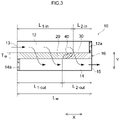
- Fig. 3 is a partial cross-sectional diagram of an enlargement of part of a cross section resulting from cutting the GPF 10 in a cylinder axis direction.
- the flow direction of exhaust gas in Figs. 2 and 3 is depicted with arrows.
- the left side in Figs. 2 and 3 is the upstream side (front side) of the exhaust pipe 4
- the right side is the downstream side (rear side) of the exhaust pipe 4.
- the reference symbol X denotes the cylinder axis direction of the GPF 10, in other words, the extension direction of the partition wall 16.
- the reference symbol Y denotes a direction, perpendicular to that of the reference symbol X, from the surface of the partition wall 16 in contact with the inlet side cells 12 towards the surface on the side in contact with the outlet side cells 14 i.e. the reference symbol Y denotes a thickness direction of the partition wall 16.
- the GPF 10 has the function of purifying harmful components contained in the exhaust gas, and trapping particulate matter (PM) contained in the exhaust gas.
- the GPF 10 is provided with a base 11 of wall flow structure, a first catalyst layer 20, and a second catalyst layer 30.
- the base 11 makes up a framework of the GPF 10.
- the base 11 is a honeycomb structure.
- conventional bases of various materials and forms that are used in this kind of applications can be used.
- a base made up of a highly heat-resistant material typified by ceramics such as cordierite, aluminum titanate, silicon carbide (SiC) and the like, and alloys such as stainless steel, can be used herein.
- the overall outer shape of the base 11 is cylindrical.
- the overall outer shape of the base 11 is not particularly limited, and for instance an elliptic cylinder shape or polygonal cylinder shape may also be adopted.
- the base 11 has inlet side cells 12 in which an end 13 on the exhaust gas inflow side is open, outlet side cells 14 in which an end 15 on the exhaust gas outflow side is open, and a partition wall 16 that partitions the inlet side cells 12 and the outlet side cells 14.
- the shape of the inlet side cells 12 and of the outlet side cells 14 is not particularly limited.
- the inlet side cells 12 and the outlet side cells 14 may adopt various geometrical shapes, such as a rectangular shape encompassing squares, parallelograms, rectangles and trapezoids, and also triangular and other polygonal shapes (for instance, hexagons and octagons), as well as circular shapes.
- a sealing section 12a is disposed at the end on the exhaust gas outflow side of the inlet side cells 12, the end on the exhaust gas outflow side being plugged by the sealing section 12a.
- a sealing section 14a is disposed at the end on the exhaust gas inflow side of the outlet side cells 14, the end on the exhaust gas inflow side being plugged by the sealing section 14a.
- the inlet side cells 12 and the outlet side cells 14 are partitioned by the partition wall 16.
- the partition wall 16 has a porous structure that allows exhaust gas to pass therethrough.
- the porosity of the partition wall 16 is not particularly limited, but may be about 20 to 70 vol%, for example 50 to 65 vol%, for instance from the viewpoint of reducing pressure loss.
- the average pore size of the partition wall 16 is not particularly limited, but may be about 5 to 30 ⁇ m and for example 10 to 20 ⁇ m, for instance from the viewpoint of reducing pressure loss.
- the partition wall 16 extends in the cylinder axis direction of the GPF 10, i.e. in the X direction.
- a total length L w of the partition wall 16 in the X direction is not particularly limited, but may be about 10 to 500 mm, for instance about 50 to 300 mm.
- the length of the partition wall 16 in the Y direction, i.e. a thickness T w of the partition wall 16, is not particularly limited, but may be for instance about 1 to 30 mils (where 1 mil is about 25.4 ⁇ m), for example from the viewpoint of reducing pressure loss.
- the first catalyst layer 20 and the second catalyst layer 30 both are disposed in the interior of the partition wall 16.
- the proportion of metal catalyst present in the interior of the partition wall 16 is typically 80 mass% or higher, for instance 90 mass% or higher, and preferably 95 mass% or higher when the entire amount of the metal catalyst in an area having a length of 0.1L w along the X direction, from the end 13 on the exhaust gas inflow side or the end 15 on the exhaust gas outflow side is taken as 100 mass%.
- This is therefore clearly distinct from an instance where, when attempting to arrange the catalyst layers on the exterior (typically on the surface) of the partition wall 16, for example part of the catalyst layer erodes unintentionally the interior of the partition wall 16.
- the first catalyst layer 20 and the second catalyst layer 30 contain a metal catalyst.
- the metal catalyst is for instance a reaction catalyst for purifying (abating) harmful components in the exhaust gas, and burning off/removing PM trapped in the pores of the partition wall 16.
- the metal catalyst various metal species capable of functioning as an oxidation catalyst or a reduction catalyst, and that are conventionally known in the relevant technical field can be appropriately used.
- Preferred examples of the metal catalyst include Rh, Pd, Pt, ruthenium (Ru), osmium (Os) and iridium (Ir), of the platinum group, as well as alloys of the foregoing.
- the metal catalyst may include for instance iron (Fe), cobalt (Co), nickel (Ni), copper (Cu), silver (Ag) and gold (Au).
- the first catalyst layer 20 and the second catalyst layer 30 contain mutually different metal species. Specifically, one from among the first catalyst layer 20 and the second catalyst layer 30 contains an oxidation catalyst, but does not contain a reduction catalyst, while the other one contains a reduction catalyst, but does not contain an oxidation catalyst.
- the oxidation catalyst include Pd, Pt and Pd-Pt alloys.
- the reduction catalyst may be a metal catalyst having a higher reducing power than that of the oxidation catalyst.
- Preferred examples of the reduction catalyst include Rh.
- the first catalyst layer 20 contains a reduction catalyst, for instance Rh.
- the second catalyst layer 30 contains an oxidation catalyst, for instance at least either one of Pd and Pt.
- the first catalyst layer 20 does not contain an oxidation catalyst, and the second catalyst layer 30 does not contain a reduction catalyst.
- the first catalyst layer 20 contains an oxidation catalyst, for instance at least either one of Pd and Pt.
- the second catalyst layer 30 contains a reduction catalyst, for instance Rh.
- the first catalyst layer 20 does not contain a reduction catalyst, and the second catalyst layer 30 does not contain an oxidation catalyst.
- the oxidation catalyst and the reduction catalyst are typically supported on a carrier.
- Carriers of various materials conventionally utilized in this kind of applications can be used herein as the carrier.
- a metal oxide such as alumina (Al 2 O 3 ), ceria (CeO 2 ), zirconia (ZrO 2 ), silica (SiO 2 ) or titania (TiO 2 ), and solid solutions of the foregoing, for instance, a zirconia-ceria complex oxide (ZC complex oxide: ZrO 2 -CeO 2 ) can be suitably used.
- ZC complex oxide ZrO 2 -CeO 2
- Preferred among the foregoing are alumina and a ZC complex oxide.
- the first catalyst layer 20 and the second catalyst layer 30 may each contain as appropriate optional components, besides the metal catalyst and the carrier on which the metal catalyst is supported.
- optional components include a co-catalyst on which a metal catalyst is not supported, an oxygen storage material (OSC (oxygen storage capacity) material) having oxygen storage capacity, a NO x adsorbent having NO x storage capacity, and a stabilizer.
- oxygen storage material oxygen storage capacity
- NO x adsorbent having NO x storage capacity
- stabilizer a stabilizer
- the co-catalyst include alumina and silica.
- the OSC material include ceria and complex oxides containing ceria, for instance a ZC complex oxide.
- stabilizers include rare earth elements such as lanthanum (La) and yttrium (Y), alkaline earth elements such as calcium (Ca) and barium (Ba), and transition metal elements. These elements are typically present in the form of oxides, in the catalyst layers.
- a stabilizer for instance barium.
- the coating amounts of the first catalyst layer 20 and the second catalyst layer 30 are not particularly limited. Each coating amount may be set to about 100 g/L or less, preferably 80 g/L or less, and for instance 70 g/L or less, per liter of volume of the base (total bulk volume including cell volume), from the viewpoint of improving circulation of exhaust gas in the partition wall 16, and better reducing pressure loss. Meanwhile, the coating amount per liter of volume of the base may be set to about 5 g/L or more, preferably 10 g/L or more and for instance 20 g/L or more, from the viewpoint of better enhancing exhaust gas purification performance. Reduction of pressure loss and enhancement of exhaust gas purification performance can both be achieved at a high level when the above ranges are satisfied.
- the first catalyst layer 20 is disposed along the extension direction (X direction) of the partition wall 16, from the end 13 on the exhaust gas inflow side.
- the first catalyst layer 20 in Fig. 3 has substantially an inverted trapezoid cross-sectional shape.
- the first catalyst layer 20 is disposed so that the length of the first catalyst layer 20 in the X direction decreases gradually from the surface of the partition wall 16 on the side in contact with the inlet side cells 12 towards the surface of the partition wall 16 on the side in contact with the outlet side cells 14.
- the second catalyst layer 30 is disposed along the extension direction (X direction) of the partition wall 16, from the end 15 on the exhaust gas outflow side.
- the second catalyst layer 30 in Fig. 3 has substantially a trapezoid cross-sectional shape.
- the second catalyst layer 30 is disposed so that the length of the second catalyst layer 30 in the X direction increases gradually from the surface of the partition wall 16 on the side in contact with the inlet side cells 12 towards the surface of the partition wall 16 on the side in contact with the outlet side cells 14.
- the first catalyst layer 20 and the second catalyst layer 30 are each disposed so as to be in contact with the inlet side cells 12 and the outlet side cells 14.
- the maximum thickness of the first catalyst layer 20 (maximum length in the Y direction) is identical to the thickness T w of the partition wall 16.
- the maximum thickness of the second catalyst layer 30 (maximum length in the Y direction) is identical to the thickness T w of the partition wall 16.
- the feature "identical to the thickness T w of the partition wall 16" herein is not to be interpreted in strict terms, and allows for errors (fluctuations of about 0.95T w to 1.05T w , preferably 0.98T w to 1.02T w , for instance 0.99T w to 1.01T w ) arising for instance from manufacturing precision.
- the area ratio of the first catalyst layer 20 and the second catalyst layer 30 differs between the surface of the partition wall 16 on the side in contact with the inlet side cells 12 and the surface of the partition wall 16 on the side in contact with the outlet side cells 14.
- a 1 -in is defined herein as the surface area of the first catalyst layer 20 and A 2 -in as the surface area of the second catalyst layer 30, on the surface of the partition wall 16 on the side in contact with the inlet side cells 12.
- a 1-out is defined herein as the surface area of the first catalyst layer 20 and A 2-out as the surface area of the second catalyst layer 30, on the surface of the partition wall 16 on the side in contact with the outlet side cells 14.
- the values of the area ratio (A 1-in /A 2-in ) and the of the area ratio (A 1-out /A 2-out ) are herein different from each other. In the present embodiment, (A 1-in /A 2-in ) > (A 1-out /A 2-out ).
- a ratio of the length of the first catalyst layer 20 in the extension direction and the length of the second catalyst layer 30 in the extension direction differ between the surface of the partition wall 16 on the side in contact with the inlet side cells 12 and the surface of the partition wall 16 on the side in contact with the outlet side cells 14.
- L 1-in is defined herein as the length of the first catalyst layer 20 in the extension direction
- L 2 -in as the length of the second catalyst layer 30 in the extension direction, on the surface of the partition wall 16 on the side in contact with the inlet side cells 12.
- L 1 -out is defined as the length of the first catalyst layer 20 in the extension direction
- L 2 -out as the length of the second catalyst layer 30 in the extension direction, on the surface of the partition wall 16 on the side in contact with the outlet side cells 14.
- values of length ratio (L 1-in /L 2-in ) and a of length ratio (L 1-out /L 2-out ) are different from each other.
- Exhaust gas purification performance can be enhanced by improving contact between the exhaust gas and the metal catalyst.
- a length L 1-in of the surface of the first catalyst layer 20 in the extension direction, on the side in contact with the inlet side cells 12, and a length L 1-out of the surface of the first catalyst layer 20, on the side in contact with outlet side cells 14, satisfy the following expression: 5% ⁇
- a length L 2-in of the surface of the second catalyst layer 30 in the extension direction, on the side in contact with the inlet side cells 12, and a length L 2-out of the surface of the second catalyst layer 30 in the extension direction, on the side in contact with outlet side cells 14, satisfy the following expression: 5% ⁇
- the effect of the art disclosed herein can be yet better brought out as a result.
- L 1-in of the first catalyst layer 20 in the extension direction, on the surface of the partition wall 16 on the side in contact with the inlet side cells 12, is not particularly limited, but in a preferred embodiment, L 1-in is about 35% or more, typically 40% or more, for instance 50% or more, with respect to 100% as the total length L w of the partition wall 16 in the extension direction, and is smaller than L w , being typically about 80% or less, typically 75% or less, and for instance 70% or less.
- L 2 -in of the second catalyst layer 30 in the extension direction is not particularly limited, but in a preferred embodiment, L 2 -in is about 20% or more, typically 25% or more, for instance 30% or more, with respect to 100% as the total length L w of the partition wall 16 in the extension direction, and is smaller than L w , being typically about 65% or less, typically 60% or less, and for instance 50% or less.
- the first catalyst layer 20 is disposed so that Li-in is a length of 40% to 75%, for instance 50% or more, of the total length L w of the partition wall 16, on the surface of the partition wall 16 on the side in contact with the inlet side cells 12.
- Li-in is a length of 40% to 75%, for instance 50% or more, of the total length L w of the partition wall 16, on the surface of the partition wall 16 on the side in contact with the inlet side cells 12.
- the total length L w of the partition wall 16, the length Li-in of the first catalyst layer 20 and the length L 2 -in of the second catalyst layer 30, on the surface of the partition wall 16 on the side in contact with the inlet side cells 12, satisfy the following expression: 0.8L w ⁇ (L 1-in + L 2 -in) ⁇ 1.2L w ; for instance the following expression: 0.9L w ⁇ (L 1-in + L 2 -in) ⁇ 1.1L w .
- the whole surface of the partition wall 16 on the side in contact with the inlet side cells 12 is covered by a at least either one of the first catalyst layer 20 and the second catalyst layer 30.
- the whole surface of the partition wall 16 on the side in contact with the inlet side cells 12 is covered by either one from among the first catalyst layer 20 and the second catalyst layer 30, as in the present embodiment.
- the flow rate of exhaust gas in the X direction can be made uniform yet better. Therefore, a reduction in pressure loss and enhancement of exhaust gas purification performance can both be achieved, at a higher level, when the above ranges are satisfied.
- the length Li-in of the first catalyst layer 20 in the extension direction is greater than the length L 2 -in of the second catalyst layer 30 in the extension direction, on the surface of the partition wall 16 on the side in contact with the inlet side cells 12. That is, L 1-in and L 2-in obey L 1-in > L 2-in .
- L 1-out of the first catalyst layer 20 in the extension direction, on the surface of the partition wall 16 on the side in contact with the outlet side cells 14, is not particularly limited, but in a preferred embodiment L 1-out is about 25% or more, typically 30% or more, for instance 40% or more, with respect to 100% as the total length L w of the partition wall 16 in the extension direction, and is smaller than L w , being typically about 70% or less, typically 65% or less, and for instance 60% or less.
- the length L 2-out of the second catalyst layer 30 in the extension direction is not particularly limited, but in a preferred embodiment L 2-out is about 30% or more, typically 35% or more, for instance 40% or more, with respect to 100% as the total length L w of the partition wall 16 in the extension direction, and is smaller than L w , being typically about 75% or less, typically 70% or less, and for instance 60% or less.
- the second catalyst layer 30 is disposed so that L 2-out is a length of 35% to 70%, for instance 40% or more, of the total length L w of the partition wall 16, on the surface of the partition wall 16 on the side in contact with the outlet side cells 14.
- L 2-out is a length of 35% to 70%, for instance 40% or more, of the total length L w of the partition wall 16, on the surface of the partition wall 16 on the side in contact with the outlet side cells 14.
- the total length L w of the partition wall 16, the length L 1 -out of the first catalyst layer 20 and the length L 2 -out of the second catalyst layer 30, on the surface of the partition wall 16 on the side in contact with the outlet side cells 14, satisfy the following expression: 0.8L w ⁇ (Li-out + L 2 -out) ⁇ 1.2L w ; for instance the following expression: 0.9L w ⁇ (L 1-out + L 2 -out) ⁇ 1.1L w .
- the whole surface of the partition wall 16 on the side in contact with the outlet side cells 14 is covered by at least either one of the first catalyst layer 20 and the second catalyst layer 30.
- the whole the surface of the partition wall 16 on the side in contact with the outlet side cells 14 is covered by either one from among the first catalyst layer 20 and the second catalyst layer 30, as in the present embodiment.
- either one of the first catalyst layer 20 and the second catalyst layer 30 is disposed throughout of the partition wall 16, i.e. throughout the partition wall 16 in the extension direction and the thickness direction.
- Such a configuration allows better reducing pressure loss, and removing harmful component from within the exhaust gas with high probability. As a result, it becomes possible to better suppress emission of insufficiently purified exhaust gas, caused by slippage of exhaust gas at the portion at which the catalyst layers are not disposed.
- the GPF 10 is further provided with a third catalyst layer 40 in which the first catalyst layer 20 and the second catalyst layer 30 overlap each other.
- the third catalyst layer 40 is a region at which the first catalyst layer 20 and the second catalyst layer 30 overlap each other in the vicinity of the interface of the first catalyst layer 20 and the second catalyst layer 30.
- the third catalyst layer 40 contains both an oxidation catalyst and a reduction catalyst, and accordingly can be regarded as a catalyst layer that is different from the first catalyst layer 20 and the second catalyst layer 30.
- the third catalyst layer 40 may be about 10% or more, for instance 20% or more, and 30% or more in an example, with respect to 100% as the volume of the whole partition wall 16, and may be about 80% or less, for instance 70% or less, and 60% or less in an example.
- the GPF 10 having a configuration as described above can be produced for instance in accordance with a method such as the one below.
- a base 11 such as that illustrated in Fig. 2 is prepare.
- Two types of slurries for catalyst layer formation namely a first slurry and a second slurry, are prepared next.
- the slurries for catalyst layer formation contain, as an essential component, respective metal catalysts (typically, a solution containing a metal catalyst in the form of ions) that are mutually different between the slurries; the slurries can also contain other optional components, for instance a carrier, a co-catalyst, an OSC material, and various additives.
- the properties of the slurries (viscosity, solids content and so forth) may be adjusted as appropriate for instance depending on the size of the base 11 that is used, the porosity of the partition wall 16 and the desired properties of the catalyst layer 20.
- the first slurry and the second slurry may be adjusted to exhibit low viscosity so that a viscosity ⁇ 400 at a temperature of 25°C and for a shear velocity of 400s -1 is 50 mPa ⁇ s or less (for instance 1 to 50 mPa ⁇ s), preferably 30 mPa ⁇ s or less, more preferably 20 mPa ⁇ s or less, and in particular 15 mPa ⁇ s or less (for instance 1 to 15 mPa ⁇ s).
- the viscosities of the first slurry and the second slurry may be set to be substantially identical (typically, so that a difference therebetween is 10 mPa ⁇ s or less, for instance so that a difference therebetween is 5 mPa ⁇ s or less).
- Slurry viscosity is herein a value measured using a commercially available shear viscometer in a temperature environment at 25°C.
- the prepared first slurry is caused to flow into the inlet side cells 12 from the end 13 on the exhaust gas inflow side of the base 11, to be supplied over a predetermined length Li-in of the partition wall 16 along the X direction.
- Suction applied from the side of the outlet side cells 14 gives rise to a pressure difference between the inlet side cells 12 and outlet side cells 14.
- the suction speed of the slurry may be set to about 10 to 100 m/s, preferably 10 to 80 m/s, and for instance 50 m/s or less, from the viewpoint of suitably forming the first catalyst layer 20 having the above-described cross-sectional shape.
- the first slurry is thereby caused to spread within the pores of the partition wall 16.
- the base 11 having the first slurry applied thereonto is then dried and fired at a predetermined temperature and for a predetermined time.
- the drying and firing methods may be similar to those resorted to in the formation of conventional catalyst layers.
- a first catalyst layer 20 having a substantially inverted trapezoid cross-sectional shape becomes formed as a result in the interior of the partition wall 16.
- the prepared second slurry is caused to flow into the outlet side cells 14 from the end 15 on the exhaust gas outflow side of the base 11, to be supplied over a predetermined length L 2 -out of the partition wall 16 along the X direction.
- the length L 2 -out of supply of the second slurry may be determined by subtracting the length L 1-out of the portion at which the first catalyst layer 20 is formed from the total length L w of the partition wall 16 in the X direction.
- Suction applied from the side of the inlet side cells 12 gives rise to a pressure difference between the outlet side cells 14 and the inlet side cells 12.
- the suction speed of the slurry may be set to about 10 to 100 m/s, preferably 10 to 80 m/s, and for instance 50 m/s or less, from the viewpoint of suitably forming the second catalyst layer 30 having the above-described cross-sectional shape.
- the second slurry is caused to spread within the pores of the partition wall 16.
- the base 11 having the second slurry applied thereonto is then dried and fired at a predetermined temperature and for a predetermined time.
- the drying and firing methods may be similar to those resorted to in the formation of conventional catalyst layers.
- a second catalyst layer 30 having a substantially trapezoid cross-sectional shape becomes formed in the interior of the partition wall 16.
- the exhaust gas emitted by the internal combustion engine 2 flows into the inlet side cells 12, from end 13 on the exhaust gas inflow side.
- the exhaust gas having flowed into the inlet side cells 12 passes through the partition wall 16 of porous structure, and reaches the outlet side cells 14.
- the first catalyst layer 20 and the second catalyst layer 30 are disposed in the interior of the partition wall 16.
- harmful components and PM are removed from the exhaust gas, as the exhaust gas passes through the first catalyst layer 20 and/or the second catalyst layer 30 inside the partition wall 16.
- the exhaust gas having reached the outlet side cells 14 through the partition wall 16 is discharged, out of the GPF 10 from the end 15 on the exhaust gas outflow side, in a state of having had harmful components and PM removed therefrom.
- Exhaust gas purification catalysts containing an oxidation catalyst and a reduction catalyst in a same catalyst layer were produced, as Comparative examples 1 to 3.
- a cordierite base of wall flow type such as the one illustrated in Fig. 2 (total length 122 mm; outer diameter 113 mm; volume 1.3 L; number of cells 300/in 2 ; average pore size 20 ⁇ m; porosity 65%) was prepared first.
- the prepared slurry A was caused to flow into the inlet side cells of the cordierite base, from the end on the exhaust gas inflow side, and was caused to coat the interior of the partition wall along the extension direction of the partition wall, in accordance with a vacuum suction method, over a length identical to the total length L w of the base along the extension direction of the partition wall, with drying and firing, to thereby form a catalyst layer.
- the coating amount of the catalyst layer per unit volume of the base was set to 88.5 g/L.
- the maximum thickness of the catalyst layer was set to 50% of the thickness T w of the partition wall, in Comparative example 1, and was set to thickness T w , identical to that of the partition wall, in Comparative example 2.
- Comparative example 1 the catalyst layer is in contact with the inlet side cells, but not in contact with the outlet side cells.
- Comparative example 2 the catalyst layer is in contact with the inlet side cells and the outlet side cells. Exhaust gas purification catalysts of Comparative examples 1 and 2 having the same catalyst layer were thus produced.
- the prepared slurry A was caused to flow into the inlet side cells of the cordierite base, from the end on the exhaust gas inflow side, and was caused to coat the interior of the partition wall along the extension direction of the partition wall, in accordance with a vacuum suction method, over a portion corresponding to 55% of the total length L w of the base along the extension direction of the partition wall, with drying and firing, to thereby form an inlet catalyst layer.
- the prepared slurry A was caused to flow into the outlet side cells from the end on the exhaust gas outflow side, and was caused to coat the interior of the partition wall along the extension direction of the partition wall, in accordance with a vacuum suction method, over a portion corresponding to 55% of the total length L w of the base along the extension direction of the partition wall, with drying and firing, to thereby form an outlet catalyst layer.
- the coating amounts of the inlet catalyst layer and of the coating amount per unit volume of the base were set to half (44.25 g/L) that in Comparative examples 1 and 2.
- the maximum thicknesses of the inlet catalyst layer and of the outlet catalyst layer both were set to a thickness T w , identical to that of the partition wall.
- An exhaust gas purification catalyst of Comparative example 3 having an inlet catalyst layer and an outlet catalyst layer was produced thus.
- the prepared Rh slurry was caused to flow into the inlet side cells of the cordierite base, from the end on the exhaust gas inflow side, and was caused to coat the interior of the partition wall along the extension direction of the partition wall, in accordance with a vacuum suction method, with drying and firing, to form as a result a first catalyst layer in the interior of the partition wall so as to be in contact with the inlet side cells and the outlet side cells.
- the coating amount of the first catalyst layer per unit volume of the base was set to 60.2 g/L.
- the first catalyst layer was formed at a portion corresponding to 70% (0.7L w ) of the total length L w of the base, on the surface of the partition wall on the side in contact with the inlet side cells.
- the maximum thickness of the first catalyst layer was set to thickness T w , identical to that of the partition wall.
- the prepared Pd slurry was caused to flow into the outlet side cells of the cordierite base, from the end on the exhaust gas outflow side, and was caused to coat the interior of the partition wall along the extension direction of the partition wall, in accordance with a vacuum suction method, with drying and firing, to form as a result a second catalyst layer in the interior of the partition wall so as to be in contact with the inlet side cells and the outlet side cells.
- the coating amount of the second catalyst layer per unit volume of the base was set to 28.3 g/L.
- the second catalyst layer was formed at a portion corresponding to 40% (0.4L w ) of the total length L w of the base, on the surface of the partition wall on the side in contact with the outlet side cells.
- the maximum thickness of the second catalyst layer was set to thickness T w , identical to that of the partition wall.
- the exhaust gas purification catalyst of Example 1 having the first catalyst layer and the second catalyst layer was thus produced.
- Fig. 4 is a graph of a comparison between the increase rates of pressure loss in Comparative examples 1 to 3 and Example 1.
- Table 1 and Fig. 4 reveal, the increase rate of pressure loss was reduced in Example 1 and Comparative examples 2 and 3 down to about half that of Comparative example 1.
- Example 1 exhibited the smallest value of increase rate of pressure loss.
- a conceivable underlying reason is that in Comparative example 1, where a catalyst layer is formed that is not in contact with the outlet side cells, the flow channels of exhaust gas are narrower at the portion where the catalyst layer is formed, which is disadvantageous for inflow of exhaust gas.
- Example 1 by contrast, where the catalyst layer is formed to a thickness identical to that of the partition wall, and so as to be in contact with the inlet side cells and the outlet side cells, it is deemed that relatively wide flow channels of exhaust gas within the partition wall are secured also after formation of the catalyst layer.
- the purification performance of the produced exhaust gas purification catalysts was evaluated in a vehicle evaluation. Specifically, firstly the exhaust gas purification catalyst of each example was installed in the exhaust passage of a gasoline direct-injection vehicle, and a catalyst inlet gas temperature was raised from 100°C to 520°C, at a rate of temperature rise of 10°C/min, using a heat exchanger. A purification rate of a NO x component was measured continuously on the basis of a ratio of inlet gas concentration and outlet gas concentration at this time, and the catalyst inlet gas temperature (T 50 -NO x ) at a time where the purification rate of the NO x component reached 50% was evaluated.
- the NO x purification rate in each example was worked out as the reciprocal of a relative value with respect to T 50 -NO x (100%) in Comparative example 1. Results are given in the corresponding column of Table 1. A higher NO x purification rate indicates that the corresponding catalyst exhibits a better NO x purification performance.
- Fig. 5 is a graph of a comparison of NO x purification rates of Comparative examples 1 to 3 and Example 1.
- Table 1 and Fig. 5 reveal, the NO x purification rate in Example 1 was dramatically higher than in Comparative examples 1 to 3.
- a conceivable underlying reason for this is that the contact frequency of exhaust gas with the catalyst layer was relatively lower in Comparative example 1.
- the oxidation catalyst and the reduction catalyst are disposed throughout the interior of the partition wall, and it is deemed that as a result grain growth and alloying occur in the metal catalyst, and the contact frequency of exhaust gas with the metal catalyst decreases.
- Example 1 by contrast, the oxidation catalyst and the reduction catalyst are disposed separately in the extension direction of the partition wall, and it is deemed that the contact frequency of exhaust gas with the metal catalyst increases as a result.
- Exhaust gas purification catalysts of Examples 2 to 4 were produced in the same way as in Example 1, but herein the lengths (L 1-in , Li-out, L 2-in , L 2 -out) of the first catalyst layer and the second catalyst layer in the extension direction of the partition wall were modified as given in Table 2. Exhaust gas purification performance was evaluated in the same way as in Test example 1-1. Results are given in the corresponding column in Table 2. Table 2 sets out relative values with respect to the NO x purification rate of Comparative example 1 (100%).
- Fig. 6 is a graph illustrating a relationship between the length of the first catalyst layer in the extension direction and NO x purification rate.
- the NO x purification rates in Examples 1 to 4 were substantially the same, and all were about 10% higher than that in Comparative example 1. From the viewpoint of NO x purification performance, therefore, it is considered that the length L 1-in of the first catalyst layer in the extension direction may be 50% to 75% with respect to 100% as the total length L w of the partition wall in the extension direction, on the surface of the partition wall on the side in contact with the inlet side cells.
- An exhaust gas purification catalyst of Example 5 was produced by reversing the first catalyst layer and the second catalyst layer of Example 1. Pressure loss and exhaust gas purification performance were evaluated in the same way as in Test example 1-1. Instead of the purification rate of the NO x component, herein the purification rate of a HC component (HC purification rate) was evaluated according to Test example 1-1 above. Results are given in the corresponding column in Table 3. Table 3 sets out relative values with respect to the HC purification rate of Comparative example 1 (100%). A higher HC purification rate indicates that the corresponding catalyst exhibits a better HC purification performance.
- Fig. 7 is a graph of a comparison of the HC purification rates of Comparative examples 1 and 2, as well as Example 1 and Example 5. As Table 3 and Fig. 7 reveal, the HC purification rate in Example 5 was better than in Example 1. From the viewpoint of HC purification performance, therefore, it is considered that the oxidation catalyst is preferably disposed in the first catalyst layer.
- the GPF 10 is further provided with the third catalyst layer 40, in addition to the first catalyst layer 20 and the second catalyst layer 30, but the GPF 10 is not limited thereto.
- the GPF 10 may have just two catalyst layers, i.e. the first catalyst layer 20 and the second catalyst layer 30.
- the exhaust gas purification catalyst gas is the GPF 10, but is not limited thereto.
- the exhaust gas purification catalyst may be a diesel particulate filter (DPF).
Landscapes
- Engineering & Computer Science (AREA)
- Chemical & Material Sciences (AREA)
- Chemical Kinetics & Catalysis (AREA)
- Combustion & Propulsion (AREA)
- Mechanical Engineering (AREA)
- General Engineering & Computer Science (AREA)
- Health & Medical Sciences (AREA)
- Materials Engineering (AREA)
- Toxicology (AREA)
- Organic Chemistry (AREA)
- Ceramic Engineering (AREA)
- Biomedical Technology (AREA)
- Environmental & Geological Engineering (AREA)
- Analytical Chemistry (AREA)
- General Chemical & Material Sciences (AREA)
- Oil, Petroleum & Natural Gas (AREA)
- Catalysts (AREA)
- Exhaust Gas After Treatment (AREA)
- Exhaust Gas Treatment By Means Of Catalyst (AREA)
- Processes For Solid Components From Exhaust (AREA)
Claims (8)
- Catalyseur de purification de gaz d'échappement (10) configuré pour être disposé dans un passage d'échappement (3, 4) d'un moteur à combustion interne (2) et qui purifie les gaz d'échappement émis par le moteur à combustion interne (2), le catalyseur comprenant :une base d'une structure à écoulement de paroi ayant une cellule côté entrée (12) dans laquelle une extrémité sur un côté d'entrée de gaz d'échappement (13) est ouverte, une cellule côté sortie (14) dans laquelle une extrémité sur un côté de sortie de gaz d'échappement (15) est ouverte, et une cloison poreuse (16) qui sépare la cellule côté entrée (12) et la cellule côté sortie (14) ; et ;une première couche de catalyseur (20) disposée à l'intérieur de la cloison poreuse (16), le long d'une direction d'extension de la cloison poreuse (16) depuis l'extrémité du côté d'entrée de gaz d'échappement (13), de manière à être en contact avec la cellule côté entrée (12) et la cellule côté sortie (14) ; etune deuxième couche de catalyseur (30) disposée à l'intérieur de la cloison poreuse (16), le long de la direction d'extension de la cloison poreuse (16) depuis l'extrémité du côté de l'écoulement de gaz d'échappement (15), de manière à être en contact avec la cellule côté entrée (12) et la cellule côté sortie (14),dans lequel l'une ou l'autre de la première couche de catalyseur (20) et de la deuxième couche de catalyseur (30) contient un catalyseur d'oxydation mais ne contient pas de catalyseur de réduction, et l'autre contient un catalyseur de réduction mais ne contient pas de catalyseur d'oxydation ; etun rapport des longueurs de la première couche de catalyseur (20) et de la deuxième couche de catalyseur (30) diffère entre une surface de la cloison poreuse (16) sur le côté en contact avec la cellule côté entrée (12) et une surface de la cloison poreuse (16) sur le côté en contact avec la cellule côté sortie (14).
- Catalyseur de purification de gaz d'échappement (10) selon la revendication 1, dans lequel
la première couche de catalyseur (20) contient un catalyseur de réduction mais ne contient pas de catalyseur d'oxydation, et la deuxième couche de catalyseur (30) contient un catalyseur d'oxydation mais ne contient pas de catalyseur de réduction. - Catalyseur de purification de gaz d'échappement (10) selon la revendication 1, dans lequel
la première couche de catalyseur (20) contient un catalyseur d'oxydation mais ne contient pas de catalyseur de réduction, et la deuxième couche de catalyseur (30) contient un catalyseur de réduction mais ne contient pas de catalyseur d'oxydation. - Catalyseur de purification de gaz d'échappement (10) selon l'une quelconque des revendications 1 à 3, dans lequel
en prenant une longueur totale de la cloison poreuse (16) dans la direction d'extension de celle-ci comme 100%, la première couche de catalyseur (20) est disposée, sur une surface de la cloison poreuse (16) sur le côté en contact avec la cellule côté entrée (12), sur une longueur de 40% à 75% de la longueur totale de la cloison poreuse (16). - Catalyseur de purification de gaz d'échappement (10) selon l'une quelconque des revendications 1 à 4, dans lequel,
en prenant une longueur totale de la cloison poreuse (16) dans la direction d'extension de celle-ci comme 100%, la deuxième couche de catalyseur (30) est disposée, sur une surface de la cloison poreuse (16) sur le côté en contact avec la cellule côté sortie (14), sur une longueur de 35% à 70% de la longueur totale de la cloison poreuse (16). - Catalyseur de purification de gaz d'échappement (10) selon l'une quelconque des revendications 1 à 5, dans lequel
la totalité de la surface de la cloison poreuse (16) sur le côté en contact avec la cellule côté entrée (12) et la totalité de la surface de la cloison poreuse (16) sur le côté en contact avec la cellule côté sortie (14) sont chacune recouvertes de l'une ou l'autre de la première couche de catalyseur (20) et de la deuxième couche de catalyseur (30). - Catalyseur de purification de gaz d'échappement (10) selon l'une quelconque des revendications 1 à 6, dans lequel
la première couche de catalyseur (20) est disposée de telle sorte que sa longueur dans la direction d'extension de la cloison poreuse (16) diminue progressivement depuis la surface de la cloison poreuse (16) sur le côté en contact avec la cellule côté entrée (12) vers la surface de la cloison poreuse (16) sur le côté en contact avec la cellule côté sortie (14) ; et
la deuxième couche de catalyseur (30) est disposée de telle sorte que sa longueur dans la direction d'extension de la cloison poreuse (16) augmente progressivement depuis la surface de la cloison poreuse (16) du côté en contact avec la cellule côté entrée (12) vers la surface de la cloison poreuse (16) du côté en contact avec la cellule côté sortie (14). - Catalyseur de purification de gaz d'échappement (10) selon l'une quelconque des revendications 1 à 7, dans lequel le moteur à combustion interne (2) est un moteur à essence.
Applications Claiming Priority (2)
| Application Number | Priority Date | Filing Date | Title |
|---|---|---|---|
| JP2017189040A JP6487982B1 (ja) | 2017-09-28 | 2017-09-28 | 排ガス浄化用触媒 |
| PCT/JP2018/033544 WO2019065206A1 (fr) | 2017-09-28 | 2018-09-11 | Catalyseur de purification de gaz d'échappement |
Publications (3)
| Publication Number | Publication Date |
|---|---|
| EP3689457A1 EP3689457A1 (fr) | 2020-08-05 |
| EP3689457A4 EP3689457A4 (fr) | 2020-10-14 |
| EP3689457B1 true EP3689457B1 (fr) | 2022-07-06 |
Family
ID=65802350
Family Applications (1)
| Application Number | Title | Priority Date | Filing Date |
|---|---|---|---|
| EP18860962.2A Active EP3689457B1 (fr) | 2017-09-28 | 2018-09-11 | Catalyseur de purification de gaz d'échappement |
Country Status (5)
| Country | Link |
|---|---|
| US (1) | US11187129B2 (fr) |
| EP (1) | EP3689457B1 (fr) |
| JP (1) | JP6487982B1 (fr) |
| CN (1) | CN111148571B (fr) |
| WO (1) | WO2019065206A1 (fr) |
Families Citing this family (9)
| Publication number | Priority date | Publication date | Assignee | Title |
|---|---|---|---|---|
| EP3501647A1 (fr) | 2017-12-19 | 2019-06-26 | Umicore Ag & Co. Kg | Filtre à particules catalityquement actif |
| EP3501648B1 (fr) | 2017-12-19 | 2023-10-04 | Umicore Ag & Co. Kg | Filtre à particules catalityquement actif |
| EP3505245B1 (fr) | 2017-12-19 | 2019-10-23 | Umicore Ag & Co. Kg | Filtre à particules à effet catalytique actif |
| EP3737491B1 (fr) * | 2019-03-29 | 2022-05-11 | UMICORE AG & Co. KG | Filtre à particules à activité catalytique |
| JP7386626B2 (ja) * | 2019-06-18 | 2023-11-27 | 株式会社キャタラー | パティキュレートフィルタ |
| JP7414413B2 (ja) * | 2019-06-26 | 2024-01-16 | 株式会社キャタラー | パティキュレートフィルタ |
| CN111997718B (zh) * | 2020-08-18 | 2022-05-17 | 无锡威孚环保催化剂有限公司 | 一种应用于柴油-天然气双燃料车的后处理方法 |
| JP7373081B2 (ja) | 2020-12-28 | 2023-11-01 | 三菱重工エンジン&ターボチャージャ株式会社 | タービンハウジング、ターボチャージャおよびガソリンエンジン |
| WO2023067744A1 (fr) * | 2021-10-20 | 2023-04-27 | 三井金属鉱業株式会社 | Catalyseur de purification de gaz d'échappement |
Family Cites Families (22)
| Publication number | Priority date | Publication date | Assignee | Title |
|---|---|---|---|---|
| JP2007185571A (ja) * | 2006-01-11 | 2007-07-26 | Toyota Central Res & Dev Lab Inc | 排ガス浄化用触媒及びその製造方法 |
| WO2008011146A1 (fr) * | 2006-07-21 | 2008-01-24 | Dow Global Technologies Inc. | Filtre à suies perfectionné à zone catalysée |
| US20080078171A1 (en) * | 2006-09-29 | 2008-04-03 | Dacosta Herbert F M | Chemically functionalized filter system |
| DE102007046158B4 (de) | 2007-09-27 | 2014-02-13 | Umicore Ag & Co. Kg | Verwendung eines katalytisch aktiven Partikelfilters zur Entfernung von Partikeln aus dem Abgas von mit überwiegend stöchiometrischem Luft/Kraftstoff-Gemisch betriebenen Verbrennungsmotoren |
| JP2009287402A (ja) | 2008-05-27 | 2009-12-10 | Nissan Motor Co Ltd | 排気浄化用フィルタ及び排気浄化装置 |
| KR101765354B1 (ko) * | 2009-11-20 | 2017-08-07 | 바스프 에스이 | 존형 촉매화 매연 필터 |
| JP2012172597A (ja) * | 2011-02-22 | 2012-09-10 | Honda Motor Co Ltd | 排気浄化フィルタ |
| GB2492175B (en) * | 2011-06-21 | 2018-06-27 | Johnson Matthey Plc | Exhaust system for internal combustion engine comprising catalysed filter substrate |
| US8789356B2 (en) * | 2011-07-28 | 2014-07-29 | Johnson Matthey Public Limited Company | Zoned catalytic filters for treatment of exhaust gas |
| US9347357B2 (en) * | 2012-09-27 | 2016-05-24 | Ngk Insulators, Ltd. | Honeycomb catalyst body |
| GB201221025D0 (en) * | 2012-11-22 | 2013-01-09 | Johnson Matthey Plc | Zoned catalysed substrate monolith |
| WO2015087816A1 (fr) * | 2013-12-11 | 2015-06-18 | 株式会社キャタラー | Matériau de purification de gaz d'échappement |
| EP3207987B1 (fr) | 2014-10-16 | 2020-08-26 | Cataler Corporation | Catalyseur pour purification des gaz d'échappement |
| US10125649B2 (en) * | 2014-10-16 | 2018-11-13 | Cataler Corporation | Exhaust gas purification catalyst |
| JP6353918B2 (ja) * | 2014-10-16 | 2018-07-04 | 株式会社キャタラー | 排ガス浄化用触媒 |
| JP6565184B2 (ja) | 2014-12-26 | 2019-08-28 | 日産自動車株式会社 | ハニカム型モノリス触媒およびその製造方法 |
| JP6472677B2 (ja) * | 2015-02-17 | 2019-02-20 | 株式会社キャタラー | 排ガス浄化用触媒 |
| CN107249738B (zh) | 2015-02-17 | 2020-10-20 | 株式会社科特拉 | 排气净化用催化剂 |
| RU2019139697A (ru) | 2015-06-18 | 2020-01-10 | Джонсон Мэтти Паблик Лимитед Компани | Зонированная система выпуска отработавших газов |
| JP6635819B2 (ja) * | 2016-02-16 | 2020-01-29 | 日本碍子株式会社 | ハニカム構造体 |
| JP6297767B2 (ja) | 2016-03-24 | 2018-03-20 | 株式会社キャタラー | 排ガス浄化装置 |
| JP6434931B2 (ja) | 2016-04-06 | 2018-12-05 | 矢崎総業株式会社 | ケーブル配索構造 |
-
2017
- 2017-09-28 JP JP2017189040A patent/JP6487982B1/ja active Active
-
2018
- 2018-09-11 US US16/647,004 patent/US11187129B2/en active Active
- 2018-09-11 WO PCT/JP2018/033544 patent/WO2019065206A1/fr unknown
- 2018-09-11 CN CN201880062609.8A patent/CN111148571B/zh active Active
- 2018-09-11 EP EP18860962.2A patent/EP3689457B1/fr active Active
Also Published As
| Publication number | Publication date |
|---|---|
| EP3689457A1 (fr) | 2020-08-05 |
| EP3689457A4 (fr) | 2020-10-14 |
| JP6487982B1 (ja) | 2019-03-20 |
| CN111148571A (zh) | 2020-05-12 |
| US20200263587A1 (en) | 2020-08-20 |
| CN111148571B (zh) | 2023-02-17 |
| US11187129B2 (en) | 2021-11-30 |
| WO2019065206A1 (fr) | 2019-04-04 |
| JP2019063700A (ja) | 2019-04-25 |
Similar Documents
| Publication | Publication Date | Title |
|---|---|---|
| EP3689457B1 (fr) | Catalyseur de purification de gaz d'échappement | |
| US10626765B2 (en) | Exhaust gas purification device | |
| US10357744B2 (en) | Exhaust gas purification device | |
| JP6527935B2 (ja) | 排ガス浄化用触媒 | |
| EP3207978B1 (fr) | Dispositif de purification des gaz d'échappement | |
| EP3254759B1 (fr) | Catalyseur de purification de gaz d'échappement | |
| EP1793914B1 (fr) | Catalyseur permettant de purifier des gaz d'echappement | |
| EP3581271A1 (fr) | Catalyseur de purification de gaz d'échappement | |
| EP2276555B1 (fr) | Catalyseur de purification de gaz d'échappement et son procédé de fabrication | |
| EP3636340B1 (fr) | Catalyseur pour la purification des gaz d'échappement | |
| EP3192584A1 (fr) | Catalyseur de purification de gaz d'échappement | |
| JP7195995B2 (ja) | 排ガス浄化用触媒 | |
| EP3673997A1 (fr) | Catalyseur de purification de gaz d'échappement | |
| EP3925681A1 (fr) | Filtre à particules | |
| JP7130622B2 (ja) | 排ガス浄化用触媒 | |
| JPH06246159A (ja) | ガスエンジン排ガス浄化用三元触媒及びガスエンジン排ガスの浄化方法 | |
| JP7178432B2 (ja) | 排気浄化フィルタ | |
| EP4205848A1 (fr) | Catalyseur de purification des gaz d'échappement | |
| JP2023000472A (ja) | 排ガス浄化触媒 |
Legal Events
| Date | Code | Title | Description |
|---|---|---|---|
| STAA | Information on the status of an ep patent application or granted ep patent |
Free format text: STATUS: THE INTERNATIONAL PUBLICATION HAS BEEN MADE |
|
| PUAI | Public reference made under article 153(3) epc to a published international application that has entered the european phase |
Free format text: ORIGINAL CODE: 0009012 |
|
| STAA | Information on the status of an ep patent application or granted ep patent |
Free format text: STATUS: REQUEST FOR EXAMINATION WAS MADE |
|
| 17P | Request for examination filed |
Effective date: 20200327 |
|
| AK | Designated contracting states |
Kind code of ref document: A1 Designated state(s): AL AT BE BG CH CY CZ DE DK EE ES FI FR GB GR HR HU IE IS IT LI LT LU LV MC MK MT NL NO PL PT RO RS SE SI SK SM TR |
|
| AX | Request for extension of the european patent |
Extension state: BA ME |
|
| A4 | Supplementary search report drawn up and despatched |
Effective date: 20200915 |
|
| RIC1 | Information provided on ipc code assigned before grant |
Ipc: B01J 35/04 20060101AFI20200909BHEP Ipc: F01N 3/022 20060101ALI20200909BHEP Ipc: F01N 3/035 20060101ALI20200909BHEP Ipc: B01J 37/02 20060101ALI20200909BHEP Ipc: F01N 3/28 20060101ALI20200909BHEP Ipc: B01J 23/63 20060101ALI20200909BHEP Ipc: B01D 53/94 20060101ALI20200909BHEP Ipc: B01J 23/58 20060101ALI20200909BHEP |
|
| DAV | Request for validation of the european patent (deleted) | ||
| DAX | Request for extension of the european patent (deleted) | ||
| REG | Reference to a national code |
Ref country code: DE Ref legal event code: R079 Ref document number: 602018037747 Country of ref document: DE Free format text: PREVIOUS MAIN CLASS: B01J0035040000 Ipc: B01J0035000000 |
|
| GRAP | Despatch of communication of intention to grant a patent |
Free format text: ORIGINAL CODE: EPIDOSNIGR1 |
|
| STAA | Information on the status of an ep patent application or granted ep patent |
Free format text: STATUS: GRANT OF PATENT IS INTENDED |
|
| RIC1 | Information provided on ipc code assigned before grant |
Ipc: F01N 3/28 20060101ALI20220126BHEP Ipc: B01J 23/63 20060101ALI20220126BHEP Ipc: B01D 53/94 20060101ALI20220126BHEP Ipc: F01N 3/022 20060101ALI20220126BHEP Ipc: F01N 3/035 20060101ALI20220126BHEP Ipc: F01N 13/00 20100101ALI20220126BHEP Ipc: F01N 3/10 20060101ALI20220126BHEP Ipc: F01N 3/021 20060101ALI20220126BHEP Ipc: B01J 35/00 20060101AFI20220126BHEP |
|
| INTG | Intention to grant announced |
Effective date: 20220221 |
|
| GRAS | Grant fee paid |
Free format text: ORIGINAL CODE: EPIDOSNIGR3 |
|
| GRAA | (expected) grant |
Free format text: ORIGINAL CODE: 0009210 |
|
| STAA | Information on the status of an ep patent application or granted ep patent |
Free format text: STATUS: THE PATENT HAS BEEN GRANTED |
|
| AK | Designated contracting states |
Kind code of ref document: B1 Designated state(s): AL AT BE BG CH CY CZ DE DK EE ES FI FR GB GR HR HU IE IS IT LI LT LU LV MC MK MT NL NO PL PT RO RS SE SI SK SM TR |
|
| REG | Reference to a national code |
Ref country code: AT Ref legal event code: REF Ref document number: 1502465 Country of ref document: AT Kind code of ref document: T Effective date: 20220715 Ref country code: CH Ref legal event code: EP |
|
| REG | Reference to a national code |
Ref country code: DE Ref legal event code: R096 Ref document number: 602018037747 Country of ref document: DE |
|
| REG | Reference to a national code |
Ref country code: IE Ref legal event code: FG4D |
|
| REG | Reference to a national code |
Ref country code: LT Ref legal event code: MG9D |
|
| REG | Reference to a national code |
Ref country code: NL Ref legal event code: MP Effective date: 20220706 |
|
| PG25 | Lapsed in a contracting state [announced via postgrant information from national office to epo] |
Ref country code: SE Free format text: LAPSE BECAUSE OF FAILURE TO SUBMIT A TRANSLATION OF THE DESCRIPTION OR TO PAY THE FEE WITHIN THE PRESCRIBED TIME-LIMIT Effective date: 20220706 Ref country code: RS Free format text: LAPSE BECAUSE OF FAILURE TO SUBMIT A TRANSLATION OF THE DESCRIPTION OR TO PAY THE FEE WITHIN THE PRESCRIBED TIME-LIMIT Effective date: 20220706 Ref country code: PT Free format text: LAPSE BECAUSE OF FAILURE TO SUBMIT A TRANSLATION OF THE DESCRIPTION OR TO PAY THE FEE WITHIN THE PRESCRIBED TIME-LIMIT Effective date: 20221107 Ref country code: NO Free format text: LAPSE BECAUSE OF FAILURE TO SUBMIT A TRANSLATION OF THE DESCRIPTION OR TO PAY THE FEE WITHIN THE PRESCRIBED TIME-LIMIT Effective date: 20221006 Ref country code: NL Free format text: LAPSE BECAUSE OF FAILURE TO SUBMIT A TRANSLATION OF THE DESCRIPTION OR TO PAY THE FEE WITHIN THE PRESCRIBED TIME-LIMIT Effective date: 20220706 Ref country code: LV Free format text: LAPSE BECAUSE OF FAILURE TO SUBMIT A TRANSLATION OF THE DESCRIPTION OR TO PAY THE FEE WITHIN THE PRESCRIBED TIME-LIMIT Effective date: 20220706 Ref country code: LT Free format text: LAPSE BECAUSE OF FAILURE TO SUBMIT A TRANSLATION OF THE DESCRIPTION OR TO PAY THE FEE WITHIN THE PRESCRIBED TIME-LIMIT Effective date: 20220706 Ref country code: FI Free format text: LAPSE BECAUSE OF FAILURE TO SUBMIT A TRANSLATION OF THE DESCRIPTION OR TO PAY THE FEE WITHIN THE PRESCRIBED TIME-LIMIT Effective date: 20220706 Ref country code: ES Free format text: LAPSE BECAUSE OF FAILURE TO SUBMIT A TRANSLATION OF THE DESCRIPTION OR TO PAY THE FEE WITHIN THE PRESCRIBED TIME-LIMIT Effective date: 20220706 |
|
| REG | Reference to a national code |
Ref country code: AT Ref legal event code: MK05 Ref document number: 1502465 Country of ref document: AT Kind code of ref document: T Effective date: 20220706 |
|
| PG25 | Lapsed in a contracting state [announced via postgrant information from national office to epo] |
Ref country code: PL Free format text: LAPSE BECAUSE OF FAILURE TO SUBMIT A TRANSLATION OF THE DESCRIPTION OR TO PAY THE FEE WITHIN THE PRESCRIBED TIME-LIMIT Effective date: 20220706 Ref country code: IS Free format text: LAPSE BECAUSE OF FAILURE TO SUBMIT A TRANSLATION OF THE DESCRIPTION OR TO PAY THE FEE WITHIN THE PRESCRIBED TIME-LIMIT Effective date: 20221106 Ref country code: HR Free format text: LAPSE BECAUSE OF FAILURE TO SUBMIT A TRANSLATION OF THE DESCRIPTION OR TO PAY THE FEE WITHIN THE PRESCRIBED TIME-LIMIT Effective date: 20220706 Ref country code: GR Free format text: LAPSE BECAUSE OF FAILURE TO SUBMIT A TRANSLATION OF THE DESCRIPTION OR TO PAY THE FEE WITHIN THE PRESCRIBED TIME-LIMIT Effective date: 20221007 |
|
| REG | Reference to a national code |
Ref country code: DE Ref legal event code: R097 Ref document number: 602018037747 Country of ref document: DE |
|
| PG25 | Lapsed in a contracting state [announced via postgrant information from national office to epo] |
Ref country code: SM Free format text: LAPSE BECAUSE OF FAILURE TO SUBMIT A TRANSLATION OF THE DESCRIPTION OR TO PAY THE FEE WITHIN THE PRESCRIBED TIME-LIMIT Effective date: 20220706 Ref country code: RO Free format text: LAPSE BECAUSE OF FAILURE TO SUBMIT A TRANSLATION OF THE DESCRIPTION OR TO PAY THE FEE WITHIN THE PRESCRIBED TIME-LIMIT Effective date: 20220706 Ref country code: MC Free format text: LAPSE BECAUSE OF FAILURE TO SUBMIT A TRANSLATION OF THE DESCRIPTION OR TO PAY THE FEE WITHIN THE PRESCRIBED TIME-LIMIT Effective date: 20220706 Ref country code: DK Free format text: LAPSE BECAUSE OF FAILURE TO SUBMIT A TRANSLATION OF THE DESCRIPTION OR TO PAY THE FEE WITHIN THE PRESCRIBED TIME-LIMIT Effective date: 20220706 Ref country code: CZ Free format text: LAPSE BECAUSE OF FAILURE TO SUBMIT A TRANSLATION OF THE DESCRIPTION OR TO PAY THE FEE WITHIN THE PRESCRIBED TIME-LIMIT Effective date: 20220706 Ref country code: AT Free format text: LAPSE BECAUSE OF FAILURE TO SUBMIT A TRANSLATION OF THE DESCRIPTION OR TO PAY THE FEE WITHIN THE PRESCRIBED TIME-LIMIT Effective date: 20220706 |
|
| REG | Reference to a national code |
Ref country code: CH Ref legal event code: PL |
|
| PLBE | No opposition filed within time limit |
Free format text: ORIGINAL CODE: 0009261 |
|
| STAA | Information on the status of an ep patent application or granted ep patent |
Free format text: STATUS: NO OPPOSITION FILED WITHIN TIME LIMIT |
|
| REG | Reference to a national code |
Ref country code: BE Ref legal event code: MM Effective date: 20220930 |
|
| PG25 | Lapsed in a contracting state [announced via postgrant information from national office to epo] |
Ref country code: SK Free format text: LAPSE BECAUSE OF FAILURE TO SUBMIT A TRANSLATION OF THE DESCRIPTION OR TO PAY THE FEE WITHIN THE PRESCRIBED TIME-LIMIT Effective date: 20220706 Ref country code: EE Free format text: LAPSE BECAUSE OF FAILURE TO SUBMIT A TRANSLATION OF THE DESCRIPTION OR TO PAY THE FEE WITHIN THE PRESCRIBED TIME-LIMIT Effective date: 20220706 |
|
| 26N | No opposition filed |
Effective date: 20230411 |
|
| PG25 | Lapsed in a contracting state [announced via postgrant information from national office to epo] |
Ref country code: LU Free format text: LAPSE BECAUSE OF NON-PAYMENT OF DUE FEES Effective date: 20220911 Ref country code: AL Free format text: LAPSE BECAUSE OF FAILURE TO SUBMIT A TRANSLATION OF THE DESCRIPTION OR TO PAY THE FEE WITHIN THE PRESCRIBED TIME-LIMIT Effective date: 20220706 |
|
| PG25 | Lapsed in a contracting state [announced via postgrant information from national office to epo] |
Ref country code: LI Free format text: LAPSE BECAUSE OF NON-PAYMENT OF DUE FEES Effective date: 20220930 Ref country code: IE Free format text: LAPSE BECAUSE OF NON-PAYMENT OF DUE FEES Effective date: 20220911 Ref country code: CH Free format text: LAPSE BECAUSE OF NON-PAYMENT OF DUE FEES Effective date: 20220930 |
|
| PG25 | Lapsed in a contracting state [announced via postgrant information from national office to epo] |
Ref country code: SI Free format text: LAPSE BECAUSE OF FAILURE TO SUBMIT A TRANSLATION OF THE DESCRIPTION OR TO PAY THE FEE WITHIN THE PRESCRIBED TIME-LIMIT Effective date: 20220706 |
|
| PG25 | Lapsed in a contracting state [announced via postgrant information from national office to epo] |
Ref country code: BE Free format text: LAPSE BECAUSE OF NON-PAYMENT OF DUE FEES Effective date: 20220930 |
|
| PGFP | Annual fee paid to national office [announced via postgrant information from national office to epo] |
Ref country code: GB Payment date: 20230921 Year of fee payment: 6 |
|
| PGFP | Annual fee paid to national office [announced via postgrant information from national office to epo] |
Ref country code: FR Payment date: 20230919 Year of fee payment: 6 Ref country code: DE Payment date: 20230919 Year of fee payment: 6 |
|
| PG25 | Lapsed in a contracting state [announced via postgrant information from national office to epo] |
Ref country code: IT Free format text: LAPSE BECAUSE OF FAILURE TO SUBMIT A TRANSLATION OF THE DESCRIPTION OR TO PAY THE FEE WITHIN THE PRESCRIBED TIME-LIMIT Effective date: 20220706 |
|
| PG25 | Lapsed in a contracting state [announced via postgrant information from national office to epo] |
Ref country code: CY Free format text: LAPSE BECAUSE OF FAILURE TO SUBMIT A TRANSLATION OF THE DESCRIPTION OR TO PAY THE FEE WITHIN THE PRESCRIBED TIME-LIMIT Effective date: 20220706 |