WO2019064648A1 - 炊飯器 - Google Patents
炊飯器 Download PDFInfo
- Publication number
- WO2019064648A1 WO2019064648A1 PCT/JP2018/012283 JP2018012283W WO2019064648A1 WO 2019064648 A1 WO2019064648 A1 WO 2019064648A1 JP 2018012283 W JP2018012283 W JP 2018012283W WO 2019064648 A1 WO2019064648 A1 WO 2019064648A1
- Authority
- WO
- WIPO (PCT)
- Prior art keywords
- induction heating
- unit
- cooking
- rice
- cooking unit
- Prior art date
- Legal status (The legal status is an assumption and is not a legal conclusion. Google has not performed a legal analysis and makes no representation as to the accuracy of the status listed.)
- Ceased
Links
Images







Classifications
-
- A—HUMAN NECESSITIES
- A47—FURNITURE; DOMESTIC ARTICLES OR APPLIANCES; COFFEE MILLS; SPICE MILLS; SUCTION CLEANERS IN GENERAL
- A47J—KITCHEN EQUIPMENT; COFFEE MILLS; SPICE MILLS; APPARATUS FOR MAKING BEVERAGES
- A47J27/00—Cooking-vessels
Definitions
- the present invention relates to a separate type rice cooker configured of a rice cooking unit that accommodates a food to be cooked inside and an induction heating and cooking unit that heats and cooks by placing the rice cooking unit on the upper surface.
- Patent Document 1 it is configured of a rice cooking unit that accommodates the food to be cooked inside, and a hollow box-shaped induction heating cooking unit that cooks by placing the rice cooking unit on the upper surface
- a separate type rice cooker is known.
- the rice cooker of Patent Document 1 can be carried to a table as a chopstick as a rice bowl and used by separating the rice cooking part and the induction heating cooking part, and the induction heating cooking part is used alone as an IH cooker can do.
- the rice cooking unit since the weight of the rice cooking unit containing rice and water is heavier than that of an ordinary pan, etc., the rice cooking unit is repeatedly placed on the induction heating cooking unit by long-term use, and the induction heating cooking unit However, there is a possibility that it may be deformed by the weight of the rice cooking section, and the facing interval between the induction heating cooking section and the rice cooking section may change, which may result in the situation that the rice cooking operation can not be performed as expected.
- the present invention is for solving the problems as described above, and the heat of the bottom surface of the heated rice cooking portion can be effectively dissipated to the outside, and the upper surface of a table or the like on which the rice cooking portion is placed is excessive.
- the first object of the present invention is to provide a rice cooker capable of preventing the situation of being heated. Moreover, the mechanical strength of the induction heating cooking part which mounts the heated rice cooking part is strengthened, and it sets it as a 2nd object to provide the rice cooker which can mount a rice cooking part stably.
- a rice cooker for the first object, comprises a rice cooking unit for containing a food to be cooked therein, and an induction heating and cooking unit for heating and cooking the rice cooking unit on an upper surface, and the induction heating
- the cooking unit has an induction heating coil for heating the rice cooking unit, and includes an infrared signal transmitting / receiving unit for transmitting an infrared signal between the induction heating cooking unit and the rice cooking unit, and the rice cooking unit has an outer shell An upper case to be formed, and an annular lower frame formed of a heat-resistant material and provided below the upper case adjacent to the lower end surface of the upper case, the lower frame includes the rice cooking portion
- the bottom wall which protrudes toward the said induction heating cooking part from the lower surface which comprises the bottom of these is provided along the outer edge part of the lower surface of the said lower frame.
- the rice cooker according to the present invention comprises a rice cooking unit for containing the food to be cooked therein, and an induction heating and cooking unit for heating and cooking the rice cooking unit on the upper surface, and the induction heating
- the cooking unit has an induction heating coil for heating the rice cooking unit, and includes an infrared signal transmitting / receiving unit for transmitting an infrared signal between the induction heating cooking unit and the rice cooking unit, and the rice cooking unit has an outer shell
- the induction heating cooking section comprises a top plate on which the rice cooking section is placed, and the induction heating cooking section comprises a top plate to be formed and an annular lower frame formed of a heat resistant material provided below the lower end face of the top case.
- the rice cooker according to the present invention comprises a rice cooking unit for containing the food to be cooked therein, and an induction heating and cooking unit for heating and cooking the rice cooking unit on the upper surface, Inside the induction heating and cooking unit, an induction heating coil for heating the rice cooking unit, an infrared signal transmitting / receiving unit for transmitting an infrared signal between the induction heating and cooking unit and the rice cooking unit, and cooling to the induction heating coil
- the induction heating and cooking unit includes a plastic upper lid, and a plastic lower case having a size overlapping with the upper lid, and the induction heating and cooking unit has the upper lid on the upper lid.
- a top plate on which the rice cooker is placed is fixed in an overlapping manner, a mounting seat for holding the induction heating coil is integrally formed on the lower surface of the upper lid, and the upper surface of the lower portion of the lower case is the cooling fan Sucking
- a partition wall extending upward at the side of the mouth is integrally formed, and a cushioning material made of a heat insulating material is disposed between the upper end of the partition wall and the lower surface of the upper lid, and the infrared signal transmitting / receiving unit is It is arrange
- the rice cooker according to the present invention comprises a rice cooking unit for containing the food to be cooked therein, and an induction heating and cooking unit for heating and cooking the rice cooking unit on the upper surface, Inside the induction heating and cooking unit, an induction heating coil for heating the rice cooking unit, a reed switch for detecting that the rice cooking unit is placed on the induction heating and cooking unit, and a cooling air to the induction heating coil A cooling fan to be supplied is provided, and the induction heating and cooking unit includes a plastic upper lid and a plastic lower case having a size overlapping with the upper lid, and the rice cooker is provided on the upper lid.
- a top plate on which the second case is placed is fixed in an overlapping manner, and a partition wall extending upward is integrally formed on the upper surface of the bottom of the lower case, and the reed switch is opposite to the cooling fan across the partition wall. Those which are location.
- the rice cooker according to the present invention comprises a top plate, an induction heating coil disposed below the top plate, and a second input operation means for inputting heating conditions of the induction heating coil.
- the rice cooking unit includes: a box-shaped induction heating cooking unit; an inner pot heated by the induction heating coil; and a rice cooking unit including a first input operation unit for inputting rice cooking conditions And heating the induction heating coil by driving the induction heating coil in a state of being placed on the top plate of the induction heating cooking part, and cooling the induction heating coil inside the induction heating cooking part.
- Cooling fan for supplying cooling air, an infrared signal transmitting / receiving unit for transmitting an infrared signal including control information for rice cooking between the induction heating and cooking unit and the rice cooking unit, and the rice cooking unit
- a transmission coil for supplying power for the control unit is provided, and the induction heating and cooking unit is vertically stacked with a plastic upper lid and a plastic lower case having a size overlapping the upper lid.
- An outer shell case is formed, and a partition wall extending in the direction of the upper lid and receiving the load of the upper lid is integrally formed on the upper surface of the lower portion of the lower case, and the power transmission coil is upward from the lower portion of the lower case It is supported by a protruding support leg.
- the lower frame of the rice cooker can prevent the heat of the bottom of the rice cooker from excessively heating the upper surface of the table or the like on which the rice cooker is placed.
- the mechanical strength of the induction heating cooking part which mounts a rice-cooking part can be strengthened, a rice-cooking part can be stably mounted, and stable rice-cooking operation can be anticipated.
- FIG. 9 is a longitudinal cross-sectional view as seen along line X1-X1 of FIG. 8;
- FIG. 9 is a longitudinal cross-sectional view as viewed along line Y1-Y1 of FIG. 8;
- FIG. 15 is a longitudinal sectional view taken along line X2-X2 in FIG.
- the rice cooker concerning Embodiment 6 of this invention WHEREIN: It is a longitudinal cross-sectional view which shows the front half part of an induction heating cooking part.
- the rice cooker which concerns on Embodiment 7 of this invention WHEREIN: It is a longitudinal cross-sectional view which shows the lower part of a rice-cooking part, and an induction heating cooking part.
- the rice cooker which concerns on Embodiment 8 of this invention WHEREIN: It is the longitudinal cross-sectional view which expanded and showed the front part of the induction heating cooking part, and the front lower part of a rice cooking part.
- the rice cooker which concerns on Embodiment 9 of this invention WHEREIN It is the longitudinal cross-sectional view which expanded and showed the left side part of the induction heating cooking part, and the left side part of the rice cooking part.
- FIG. 1 is the external appearance perspective view which looked at the rice cooker 100 which concerns on Embodiment 1 from the upper surface side.
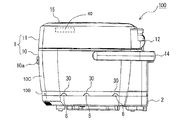
- FIG. 2 is a side view of rice cooker 100 according to the first embodiment.
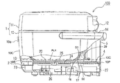
- FIG. 3 is the rice cooker 100 which concerns on Embodiment 1, Comprising: It is the side view which fractured partially and showed the internal structure.
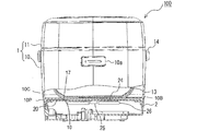
- FIG. 4 is the rice cooker 100 which concerns on Embodiment 1, Comprising: It is the front view which partially broken and showed the internal structure.
- FIG. 5 is the external appearance perspective view which looked at the rice cooking part 1 of the rice cooker 100 which concerns on Embodiment 1 from the bottom face side.
- Rice cooker 100 includes a rice cooking unit 1 containing a food to be cooked therein, and an induction heating cooking unit 2 heating and cooking the rice cooking unit 1 on the upper surface. It is a configured separate type rice cooker.
- the rice cooker 100 can separate and use the rice cooking part 1 and the induction heating cooking part 2 independently, respectively. That is, the rice cooker 100 can be carried to the table as a chopstick and used as a rice cooker 1 which is separated, and the induction heating and cooking unit 2 which is separated can be used as an IH cooker.
- a control unit 40 see FIG. 2 and a control unit 23 (see FIG.
- the control unit 23 and the control unit 40 each use a microcomputer in a central control unit as a core.
- the induction heating and cooking unit 2 Since the induction heating and cooking unit 2 has a power cord provided at one end with a power plug that can be connected to a household power supply, the induction heating and cooking unit 2 can be used alone.
- the rice cooking unit 1 operates the induction heating cooking unit 2 connected to the power source, receives power from the induction heating coil 24 built in the induction heating cooking unit 2 by the non-contact power feeding method. . That is, the rice cooking unit 1 can not operate alone without the power supply unit 29 described later.
- non-contact electric power feeding is a power receiving coil 51 (see FIG. 3) provided at the bottom of the rice cooking section 1 and a power transmitting coil 50 disposed at the ceiling of the induction heating cooking section 2 so as to be located just below the power receiving coil 51. (See FIG. 3).
- the power supply unit 29 is provided in the space behind the inner hook 13.
- the power supply unit 29 is configured of, for example, a secondary battery such as a lead storage battery, a nickel hydrogen storage battery, or a lithium ion storage battery.
- the electric power feeding part 29 is not limited to being comprised by a secondary battery, You may be comprised by the primary battery of a dry cell etc.
- FIG. As described above, when the feeding unit 29 is configured of a primary battery, it is preferable to provide the primary battery of the feeding unit 29 in a position where it can be easily replaced in consideration of the possibility of replacing the feeding unit 29. .
- the control unit 40 of the rice cooking unit 1 is operated by the power obtained by the power receiving coil 51. Further, the first display unit 42 also performs a display operation with the power obtained by the power receiving coil 51.
- the rice cooking portion 1 is rotatably connected to the main body portion 10 by the main body portion 10 having the upper surface opened and the hinge mechanism portion 12 so that the upper surface opening of the main body portion 10 can be opened and closed. And a cover 11 for covering.
- the main body portion 10 has a cylindrical shape with a bottom, and the inner hook 13 is detachably mounted inside.
- a lid open / close button 10 a for opening and closing the lid 11 is provided on the front side of the main body 10. The user can release the closed state of the lid 11 by pushing the lid open / close button 10 a, and can open the main body portion 10.
- a handle 14 is attached to the main body portion 10 when the rice cooking portion 1 is separated from the induction heating cooking portion 2 and carried.
- the handle 14 is substantially U-shaped, and both end portions thereof are rotatably attached to the left and right side surfaces of the main body portion 10, respectively.
- a bottom wall 10P projecting from the bottom toward the induction heating and cooking portion 2 is provided along the outer edge of the bottom.
- the bottom wall 10P is formed with a wall opening 30 communicating the inside surrounded by the bottom wall 10P with the outside.
- the main body portion 10 is provided below the upper case 10C so as to cover the entire opening of the bottom surface of the upper case 10C and the lower surface of the upper case 10C integrally formed in a cylindrical shape from a plastic material forming the outer shell And an annular lower frame 10B formed of an elastic material.
- the lower frame 10B is coupled to the upper case 10C with a screw (not shown) so as to cover the bottom surface of the upper case 10C, and a bottom wall 10P from which the lower portion of the lower frame 10B protrudes toward the induction heating cooking portion 2 It becomes.
- the material of the lower frame 10B is, for example, PET or PA.
- the material of the upper case 10C is PP or ABS.
- PET refers to polyethylene terephthalate.
- PA means a polyamide
- PP means a polypropylene.
- a large circular hole 16 is formed at the center of the lower frame 10B.
- the container 17 is formed in a bottomed cylindrical shape and covers the periphery of a bottomed cylindrical inner pot 13 described later. The bottom of the container 17 fits tightly in the hole 16 and seals the hole 16.
- the material of the container 17 is, for example, PET or PA.
- the broken line PL1 is a horizontal line indicating the position of the top surface of the lower frame 10B.
- the lower frame 10B is a part having a small height (about 10 mm to 20 mm) and an annular (ring-like) planar shape.
- the broken line PL1 shown in FIG. 3 indicates the height (range) at which the boundary between the upper case 10C and the lower frame 10B can be recognized on the appearance of the rice cooker 1.
- PL1 is referred to as a "first separation line”.
- the wall surface opening 30 is a trapezoidal notch which is formed by notching the bottom wall 10P of the lower frame 10B.
- a plurality of wall surface openings 30 (12 in the illustrated example) are formed at intervals along the entire circumference of the lower frame 10B.
- the wall surface opening part 30 carries the heat of the bottom surface of the heated rice cooking part 1 to the outside, when the rice cooking part 1 separated from the induction heating cooking part 2 is carried on a table as a so-called chopsticks and placed on a table etc. It is formed for the purpose of escape.
- the wall opening 30 is preferably formed in the bottom wall 10P of the lower frame 10B so as to face each other in the front, rear, left, and right of the main body 10 in order to form air convection.
- the shape, size, and number of the wall surface opening 30 are not limited to the illustrated form.
- the wall opening 30 may be, for example, a rectangular hole or a circular hole whose circumference is enclosed. Further, the wall surface opening 30 may be a cut-out hole cut in an arc shape. In short, the wall surface opening 30 is appropriately changed in design according to the size of the main body 10 and provided.
- the main body portion 10 has an intake hole 4 formed in the bottom and an exhaust hole 5 formed in a side surface on the back side and communicating with the intake hole 4 There is. That is, in the rice cooking portion 1, the inside surrounded by the bottom wall 10 P is in communication with the outside by the intake hole 4 and the exhaust hole 5. Thereby, since the rice cooking part 1 can form the convection of air by the intake hole 4 and the exhaust hole 5, the heat of the bottom face of the rice cooking part 1 heated by the air which flowed in from the wall surface opening part 30 is taken. It can escape to the outside through the exhaust hole 5 from 4.
- the exhaust hole 5 is not limited to the structure formed in the side by the side of the back of the main-body part 10.
- the exhaust hole 5 may be provided, for example, on the other side of the main body 10 or the lid 11.
- the exhaust hole 5 may be provided at any position of the rice cooker 1 as long as it can communicate with the intake hole 4 to form a convection of air with the wall opening 30.
- the rice cooker 100 of Embodiment 1 does not necessarily need to provide the intake hole 4 and the exhaust hole 5, and the heat of the bottom face of the heated rice cooking part 1 is dissipated outside only by the wall surface opening part 30. Good.
- the inner pot 13 has a bottomed cylindrical shape and is made of a carbon material that generates heat by induction heating.
- the inner pot 13 may be, for example, a container (a so-called earth pot) formed of a nonmetal material such as ceramic or a metal container using a clad material of aluminum and stainless steel or the like. Inside the inner pot 13, the rice and water which are to-be-cooked goods are accommodated.
- the lid 11 covers the top opening of the main body 10 so as to be openable and closable.
- the lid 11 has its rear end connected to the top of the main body 10 by the hinge mechanism 12.
- the lid 11 can be pivoted about the hinge axis of the hinge mechanism 12 when the lid opening / closing button 10 a is pressed in a closed state.
- the lid 11 is provided with a steam port 11 a for releasing the steam generated inside the rice cooker 1.
- the lid 11 is provided with a first input operation unit 15 to which the user can input rice cooking conditions and the like.
- the first input operation unit 15 is an operation unit that receives an operation input for executing, for example, a preheating process, a rice cooking process, an unevenness process, and the like.
- the first input operation unit 15 is connected to the control unit 40 shown in FIG. 2 and transmits an input operation signal as an infrared signal to the induction heating and cooking unit 2 through the infrared signal transmission / reception unit 41 (not shown). Be done.
- the first input operation unit 15 has a configuration in which a plurality of press-type input keys 15A are arranged, the first input operation unit 15 may be a touch-type input key 15A, or both may be used in combination.
- a first display unit 42 is provided on the left and right for displaying the input operation result by the first input operation unit 15 or the rice cooking operation with numbers, characters, symbols or the like.
- the first display unit 42 is configured of, for example, a liquid crystal display substrate provided with a liquid crystal display screen.
- FIG. 6 is an external perspective view showing the induction heating and cooking unit 2 of the rice cooker 100 according to the first embodiment.
- FIG. 7 is an external perspective view showing a different form of the induction heating and cooking unit 2 of the rice cooker 100 according to the first embodiment.
- the induction heating and cooking unit 2 is, for example, a tabletop electromagnetic cooker that is used by being placed on a table or the like.
- the induction heating and cooking unit 2 has a substantially rectangular parallelepiped shape with a thin external appearance.
- a top plate 20 made of a heat-resistant material such as crystallized glass is provided on the top surface of the induction heating and cooking unit 2.
- the induction heating and cooking section 2 is formed with a stepped portion 21 recessed downward along the outer peripheral edge of the top plate 20.
- the lower end surface of the bottom wall 10P (lower frame 10B) of the rice cooker 1 abuts on the stepped portion 21 of the induction heating cooking portion 2, and the bottom wall 10P is formed in such a shape and size that the bottom wall 10P fits tightly. That is, when the rice cooker 100 places the rice cooker 1 on the induction heating cooker 2, the bottom wall 10P of the rice cooker 1 fits into the step 21 of the induction cooker 2 and the top plate 20 is the bottom wall 10P. It will be stored inside the
- the stepped portion 21 of the induction heating and cooking unit 2 is provided with a protrusion 6 fitted to the wall surface opening 30 at a position facing the wall surface opening 30. This is because when the cooking unit 1 is placed on the upper surface of the induction heating and cooking unit 2 for heating and cooking, the wall opening 30 is closed with the protrusion 6 and the heat heated by the induction heating and cooking unit 2 is prevented from leaking to the outside.
- the side surface of the rice cooker 100 is made into a flat state without a hole, and it is also for improving the cleaning property at the time of wiping off dirt with cloth etc.
- the protrusion 6 is provided such that its tip end is lower than the top plate 20 of the induction heating unit 2. This is a case where the rice cooking part 1 is separated and the induction heating cooking part 2 is used alone as an IH cooker, and when the cooking container is placed on the top plate 20, the presence of the projection 6 does not get in the way To enable the use of cooking containers of various sizes. Moreover, it is also for making the bottom face of a cooking container contact the top plate 20 of the induction heating cooking part 2, and ensuring induction heating efficiency.
- FIG. 7 is the external appearance perspective view which showed the different form of the induction heating cooking part 2 of the rice cooker 100 which concerns on Embodiment 1.
- the protrusion 7 may be provided so that the tip end portion is above the top plate 20 of the induction heating and cooking portion 2.
- the protrusion 7 limits the range of movement of the cooking container, so the cooking container may be tilted during cooking, or may be accidentally misplaced from the top plate 20. It is possible to prevent a situation such as falling.
- the induction heating and cooking unit 2 is provided with a second input operation unit 22 on the front side of the upper surface.
- the second input operation unit 22 is provided with various press-type input buttons 22A, and is connected to the control unit 23.
- the various input buttons 22A are used to input various conditions such as a thermal power, a cooking menu, and a cooking time.
- the induction heating and cooking unit 2 can perform induction heating and cooking independently of the rice cooking unit 1 by operating the second input operation unit 22.
- the second input operation unit 22 is housed together with the top plate 20 in the bottom wall 10P when the rice cooking unit 1 and the induction heating cooking unit 2 are combined. ing. In other words, the second input operation unit 22 is covered with the rice cooker 1 so that the user can not operate it.
- a second display unit 28 is provided on the left and right for displaying the input operation result by the second input operation unit 22 or the induction heating operation and the like by numbers, characters, symbols or the like.
- the induction heating coil 24, the temperature sensor 25, the ferrite 26, the power supply substrate 27, and the power transmission coil 50 are provided inside the induction heating cooking part 2, respectively.
- the induction heating coil 24 is disposed substantially at the center of the inside of the induction heating cooking unit 2 and is controlled by the control unit 23 based on the operation input of the first input operation unit 15 and the second input operation unit 22. .
- the induction heating coil 24 generates an alternating magnetic field by energization to heat the object to be heated by electromagnetic induction.
- the temperature sensor 25 is provided to detect the temperature of the inner hook 13 or the top plate 20 and is connected to the control unit 23.
- the ferrite 26 has an elongated plate shape, and is provided to be orthogonal to the winding of the induction heating coil 24.
- the ferrite 26 is provided in order to concentrate magnetic lines of force generated from the induction heating coil 24 on the object to be heated above the top plate 20.
- a power supply substrate 27 is provided on the back side inside the induction heating and cooking unit 2.
- the power supply substrate 27 includes a converter for converting AC power of commercial power into DC power, an inverter for converting DC power from the converter to AC power and supplying the same to the induction heating coil 24, and a control circuit for controlling the inverter. Has been implemented.
- the power supply substrate 27 is connected to the control unit 23 via a signal line.
- the infrared signal transmission / reception part 62 which receives the input operation signal (infrared ray signal) transmitted from the infrared signal transmission / reception part 41 (not shown) of the rice cooking part 1 is accommodated in the induction heating cooking part 2, Not shown.
- the infrared signal transmission / reception unit 41 and the infrared signal transmission / reception unit 62 are infrared communication terminals (communication units), and each include a reception unit and a transmission unit of an infrared signal.
- An input operation signal, a temperature detection signal of the inner pot 13 and the like are transmitted from the rice cooking unit 1 to the induction heating and cooking unit 2 each time.
- an identification signal for confirming that the rice cooking unit 1 is placed on the regular position is transmitted by infrared rays from the induction heating cooking unit 2 to the rice cooking unit 1, and a regular signal from the rice cooking unit 1 is transmitted.
- a response signal is received.
- the control unit 23 of the induction heating and cooking unit 2 executes various controls such as the start of energization of the induction heating coil 24 or the transmission coil 50, the amount of energization, and the stop of energization according to the reception of the infrared signal from the rice cooking unit 1.
- the linear distance between the induction heating coil 24 and the inner pot 13 should be small so that the inner pot 13 can be efficiently inductively heated by the induction heating coil 24.
- the bottom surface of the inner pot 13 is in close proximity to or in close contact with the container 17 constituting the bottom surface of the rice cooker 1.
- the upper surface of the table is heated by the bottom surface of the rice cooking part 1 heated by the induction heating cooking part 2. That is, since the temperature of the container 17 itself which is partially exposed to the bottom of the rice cooker 1 is high, if a sheet such as a table cloth that is easily deformed by heat from the container 17 is laid on the upper surface of the table, The sheet may be heated by the rice cooker 1 to be deformed or the like. There is also concern about the deformation of the table itself.
- the bottom surface wall 10P which protrudes toward the induction heating cooking part 2 from the bottom surface is provided in the rice cooking part 1 of the rice cooker 100 of Embodiment 1 along the outer edge part of the bottom surface.
- the bottom wall 10P is formed with a wall opening 30 communicating the inside surrounded by the bottom wall 10P with the outside. With the wall opening 30 formed, the rice cooker 100 is heated even when the rice cooking unit 1 separated from the induction heating cooking unit 2 is carried as a chopstick to a table and placed on a table etc. The heat of the bottom of the rice cooker 1 can be dissipated to the outside through the wall opening 30. Therefore, in rice cooker 100 of Embodiment 1, the situation where the upper surface of the table or the like is excessively heated can be prevented.
- the wall opening 30 is a notch formed by cutting the lower frame 10B, and the wall surface is positioned opposite to the wall opening 30 of the induction heating cooking unit 2.
- a projection 6 is provided which fits into the opening 30. Therefore, when the rice cooker 100 places and cooks the rice cooker 1 on the upper surface of the induction heating cooker 2, the wall opening 30 can be closed with the protrusion 6, and thus the rice cooker 100 is heated by the induction cooker 2. The heat cooking effect can be enhanced without leakage of heat to the outside.
- step-difference part 21 recessed below along the outer periphery of the upper surface which cooks the rice cooking part 1 is formed.
- the protruding portion 6 is provided in the step portion 21 so that the tip end portion is lower than the upper surface of the induction heating and cooking portion 2. Therefore, the rice cooker 100 is a case where the rice cooking unit 1 is separated and the induction heating cooking unit 2 is used alone as an IH cooker, and when the cooking container is placed on the upper surface, the presence of the protrusion 6 is in the way Also, it is easy to use because it can be used for cooking containers of various sizes.
- the protrusion 6 may be provided in the step 21 so that the tip end is above the upper surface of the induction heating and cooking unit 2.
- the rice cooker 100 uses a small cooking container that fits on the upper surface of the induction heating cooking unit 2, the movement range of the cooking container is limited by the protrusions 7, so the cooking container may tilt during cooking or induction heating It is possible to prevent a situation such as accidental dropping from the upper surface of the cooking unit 2.
- the rice cooker 1 of the rice cooker 100 according to the first embodiment has an intake hole 4 formed on the bottom and an exhaust hole 5 formed on the outer side and communicating with the intake hole 4.
- the intake holes 4 and the exhaust holes 5 since convection of air can be formed by the intake holes 4 and the exhaust holes 5, the heat of the bottom surface of the rice cooker 1 heated by the air flowing from the wall surface opening 30. Can be discharged from the intake port 4 to the outside through the exhaust port 5. Therefore, in rice cooker 100 of Embodiment 1, the situation where the upper surface such as the table is excessively heated can be prevented more effectively.
- Rice cooker 100 shown in the first embodiment has the following configuration. That is, The cooking unit includes: a rice cooking unit 1 for accommodating the food to be cooked therein; and an induction heating and cooking unit 2 for heating and cooking the rice cooking unit 1 on an upper surface thereof;
- the rice cooker 1 includes an upper case 10C forming an outer shell, and an annular lower frame 10B formed of a heat resistant material provided below the upper case 10C adjacent to the lower end surface of the upper case 10C.
- a bottom wall 10P projecting toward the induction heating cooking unit 2 from the lower surface of the lower frame 10B constituting the bottom of the rice cooking unit 1 is an outer edge portion of the lower surface of the lower frame 10B (bottom of the rice cooking unit 1) Provided along the
- the lower frame 10B of the rice cooking unit 1 can prevent the heat of the bottom surface of the rice cooking unit 1 from excessively heating the upper surface of the table or the like on which the rice cooking unit 1 is placed.
- FIG. 8 is a plan view of the induction heating and cooking unit 2 of the rice cooker 100 according to the second embodiment.
- FIG. 9 is a longitudinal cross-sectional view as viewed along line X1-X1 of FIG.
- the rice cooking part 1 has shown only the lower end part.
- FIG. 10 is a longitudinal cross-sectional view as viewed along line Y1-Y1 of FIG. Description of the same parts as those of the first embodiment may be omitted.
- the same or corresponding parts as in the first embodiment are denoted by the same reference numerals.
- the rice cooker 100 which concerns on Embodiment 2 is devised so that the mechanical strength of the induction heating cooking part 2 which mounts the rice cooking part 1 may be strengthened, and the rice cooking part 1 can be stably mounted.
- an induction heating coil 24 having a circular planar shape is disposed on the left and right center line of the induction heating cooking part 2 so that the center part is located.
- the cooling fan 60 When viewed from the center point of the induction heating unit 2, the cooling fan 60 is located slightly forward on the right side.
- the cooling fan 60 has the air intake port 77 (see FIG. 9) disposed at a position immediately below, sucks cool air from the air intake port 77, and supplies it as the cooling air to the inside of the first air passage SH1.
- the air intake port 77 In the air intake port 77, a long narrow slit-like hole is arranged or a large number of small diameter holes are arranged.
- Plastic parts such as the upper lid 2B and the lower case 2C are generally manufactured using an injection molding machine. If the injection molding is carried out with a small amount of granular plastic material called pellets, the weight of the completed upper lid 2B and lower case 2C can be reduced and the cost can be reduced. However, if the amount of material is reduced, the part becomes thin and weak in strength.
- pillar 74 integrally formed from the lower case 2C and protruded upwards is disperse
- the reinforcement effect can be expected by forming the support 74 in the vertical direction to receive the load.
- the support 74A and the support 74B are the support 74 in front of the rice cooker 100, which is located close to the second input operation unit 22.
- the support 74C and the support 74D are the support 74 at the back of the rice cooker 100, which are installed several centimeters apart in the right and left directions of the induction heating coil 24.
- the cross sections of the columns 74A and 74B are perfect circles.
- the support 74C and the support 74D are formed in an oval shape in which the cross-sectional shape is long in the front-rear direction and the surface is a smooth curved surface, and is configured not to disturb the flow of the cooling air of the cooling fan 60 as much as possible.
- the portion of the second input operation unit 22 is arranged with the support 74A and the support 74B for reinforcement in consideration of receiving a load from above in particular.
- the support 74C and support 74D formed on the right side and the left side of the induction heating coil 24 have a heated object such as the inner pot 13 containing rice and water or a pot containing water and food just above the opening 2H of the upper lid 2B. It is placed to receive the load in a distributed manner.
- the inner pot 13 or the like of the rice cooker 1 is placed at a position directly above the induction heating coil 24. Therefore, when the top plate 20 at a position just above the induction heating coil 24 receives a load, a force is exerted to push down the edge of the opening 2H of the upper lid 2B just below it.
- the supports 74C and 74D are disposed on the right and left sides of the position of the induction heating coil 24, the edge of the opening 2H of the upper lid 2B is supported by the supports 74C and 74D from below. As a result, it is possible to prevent the curvature and the like of the upper lid 2B.
- the partition wall 61 formed integrally with the bottom surface of the lower case 2C is provided.
- the partition wall 61 includes a front arc portion 61C, a right side portion 61R, and a left side portion 61L.
- the front arc portion 61C is on the front side of the lower case 2C and crosses the front side of the cooling fan 60.
- the right side portion 61R extends linearly in the rear of the lower case 2C continuously with the rear end face of the front arc portion 61C.
- the left side portion 61L extends linearly in the rear of the lower case 2C continuously with the rear end surface of the front arc portion 61C.
- the infrared signal transmitting / receiving unit 62 is composed of two components, an infrared light emitting element 62S (infrared signal transmitting section) and an infrared light receiving element 62R (infrared signal receiving section). ing. Both signals of the infrared light emitting element 62S and the infrared light receiving element 62R are analyzed and processed by one communication control unit 62C, and the communication control unit 62C outputs the transmission / reception data analysis result to the control unit 23.
- the power transmission coil 50 has an annular outer shape. As apparent from FIG. 8, it is the infrared signal transmitting / receiving unit 62 that is located closest to the cooling fan 60 in the first air blowing passage SH1.
- the power transmission coil 50 is upstream of the induction heating coil 24 in the flow of cooling air in the first air passage SH1, and is separated from the induction heating coil 24 by about 10 cm in linear distance. Due to this positional relationship, the power transmission coil 50 is neither exposed to the warm air after cooling the induction heating coil 24 nor inductively heated by the alternating magnetic field emitted by the induction heating coil 24.
- the reed switch 18 is a magnetic proximity switch that receives a magnetic force and closes an electrical contact.
- a part of two nickel alloy (magnetic material) leads is overlapped and sealed in a glass tube, and the overlapping portion is subjected to contact processing such as gold or silver. It is done.
- contact processing such as gold or silver. It is done.
- an inert gas is enclosed in the glass tube in order to prevent the activation of the contacts.
- a permanent magnet 19 (not shown) that emits a magnetic force so as to close the reed switch 18 is installed at the bottom of the rice cooker 1.
- the induction heating and cooking unit 2 includes a cooling fan 60, an induction heating coil 24, a power transmission coil 50, a partition wall 61, a control unit 23, and a second input operation unit 22 in the internal space of the induction heating and cooking unit 2. And an infrared signal transmitting / receiving unit 62.
- the induction heating coil 24 is formed in a disk shape.
- the partition wall 61 forms a first air passage SH1 and a second air passage SH2 in the internal space of the induction heating and cooking unit 2.
- the infrared signal transmitting and receiving unit 62 constitutes an infrared communication unit of the induction heating and cooking unit 2.
- the induction heating coil 24 is installed on a support frame 63 called a coil base formed of heat resistant plastic or the like.
- a support frame 63 a large number of through holes 63A having a large opening area are formed in order to increase air permeability.
- the induction heating and cooking unit 2 is configured of an outer shell case 2A by a bottomed box-shaped lower case 2C constituting the outer shell of the induction heating and cooking unit 2 and an upper lid 2B covering the entire upper surface of the lower case 2C. ing.
- the lower case 2C and the upper lid 2B are formed by plastic integral molding (injection molding method). Therefore, the material is a thermoplastic plastic.
- the lower case 2C and the upper lid 2B are shaped so as to completely overlap each other in plan view. In other words, the projected area when projecting up and down is the same. Further, since the upper lid 2B is used in a higher temperature environment than the lower case 2C, a material having higher heat resistance than the lower case 2C is selected.
- the planar size of the lower frame 10B is close to the planar shape of the upper lid 2B.
- the external shape of the entire rice cooker 100 is a box shape whose planar shape is close to a square, as in the first embodiment shown in FIG.
- the upper lid 2B is securely fixed to the lower case 2C by fixing means such as screws (not shown).
- the top plate 20 covers the large square opening 2H formed in the central portion of the lower frame 10B, and is made of highly heat-resistant crystallized glass or a plastic material such as PET or PPS. Just above the top plate 20, the bottom of the inner hook 13 is disposed in contact with or in proximity to the top plate 20.
- the top plate 20 has a diameter larger than the largest outside diameter dimension of the induction heating coil 24.
- a horizontal line PL2 shown in FIG. 9 indicates that the boundary between the upper cover 2B and the lower case 2C can be recognized on the appearance of the induction heating and cooking unit 2.
- the horizontal line PL2 is a horizontal position at which the lower case 2C and the upper lid 2B are overlapped when manufacturing the outer shell of the induction heating and cooking unit 2.
- the horizontal line PL2 is hereinafter referred to as a "second separation line”.
- the support 74B is a front support 74 among the four supports 74 integrally formed on the upper surface of the lower case 2C.
- the support 74A and the support 74B are respectively formed at the back position of the second input operation means of the induction heating and cooking unit 2 so as to face each other.
- the columns 74C and 74D are disposed at the left and right positions of the induction heating coil 24 because the induction heating coil 24 is disposed at the center of the lower case 2C.
- convex portions 73 integrally formed at two positions on the lower surface of the upper lid 2B are provided, and the convex portions 73 are positioned directly above the columns 74A and 74B.
- the support 74A and the convex portion 73, and the support 74B and the convex portion 73 are in contact or in a minute gap. It will be in the state of facing each other. Therefore, the load applied to the upper surface of the upper lid 2B can be expected to be supported by the support 74A and the support 74B.
- the inclusions are not limited to solids, and may be, for example, a half-softened material such as a silicone rubber sealing material.
- the partition wall 61 divides the space enclosed by the lower case 2C and the upper lid 2B into two spaces, front and back, as shown in FIG.
- the infrared signal transmitting / receiving unit 62 includes an infrared light emitting element 62S, an infrared light receiving element 62R, a support substrate 62B to which the infrared light emitting element 62S and the infrared light receiving element 62R are attached, and a communication control section 62C.
- the support substrate 62 B is horizontally fixed on the top surface of the partition wall 61.
- the cooling fan 60 for cooling the inside of the induction heating and cooking unit 2 is disposed in close proximity to the intake port 77 formed on the front bottom wall of the lower case 2C.
- the cooling fan 60 for example, an axial flow fan is used.
- the fan motor 60M is installed immediately above the air inlet 77, and the cooling fan 60 is rotationally driven by the fan motor 60M.
- the fan motor 60M is fixed to the upper surface of a circular fan case 60C having a support leg with an inverted U-shaped vertical cross section, which is integrally formed with the lower case 2C so as to straddle the upper side of the air inlet 77.
- the heating circuit board 80 mounts the inverter circuit which supplies high frequency electric power with respect to the induction heating coil 24, and various electric components, such as a semiconductor power control element and a switching element, are mounted.
- various electric components such as a semiconductor power control element and a switching element, are mounted.
- a semiconductor power control element such as an IGBT is mounted on a heat radiation fin 81 (or “heat sink”) made of aluminum in order to dissipate heat generated during the control operation.
- a support convex portion 114 for supporting the heating circuit board 80 is provided on the bottom surface of the lower case 2C.
- a plurality of support convex portions 114 are provided on the bottom surface of the lower case 2C by integral molding.
- An electrically insulating sheet 83 (or a thin plate) is provided immediately above the heat dissipating fins 81.
- the sheet 83 is provided horizontally above the radiation fins 81 for the purpose of enhancing the insulation between the induction heating coil 24 and the heating circuit board 80.
- the electrically insulating sheet 83 (or thin plate) is made of a plastic material such as PP or PET. As shown in FIG. 9, the electrically insulating sheet 83 is horizontally provided right above the radiation fin 81 so as not to prevent the flow of the cooling air supplied from the cooling fan 60.
- thick solid arrows indicate the flow of the cooling air supplied from the cooling fan 60. Also, thick dashed arrows indicate the intake flow introduced into the cooling fan 60.
- An exhaust port 108 is formed in the rear rear wall of the lower case 2C.
- a plurality of exhaust ports 108 are formed side by side in order to discharge the cooling air from the cooling fan 60.
- a temperature sensor 25 is provided on the back surface (lower surface) of the upper lid 2B.
- the temperature sensor 25 is a contact type temperature sensor that contacts the back surface (bottom surface) of the upper lid 2B to measure the temperature of the top plate 20, and a thermistor type temperature detection element is used. Temperature measurement data of the temperature sensor 25 is transmitted to the temperature detection circuit 104 through the signal line 105, and information on the temperature grasped by the temperature detection circuit 104 is transmitted to the control unit 23.
- the thermistor (temperature detection element) is installed so as to penetrate the central portion (hollow portion) of the induction heating coil 24 having a hollow annular shape in plan view as shown in the drawing.
- An alternate long and short dash line CL indicates the vertical center line of the induction heating coil 24 and also coincides with the vertical center line of the temperature sensor 25.
- the temperature detection circuit 104 is connected to the temperature sensor 25 through a signal line 105, and receives temperature data measured by the temperature sensor 25.
- the control unit 23 and the temperature detection circuit 104 are mounted on the control circuit board 106.
- a support convex portion 115 for supporting the control circuit board 106 is provided on the bottom surface of the lower case 2C.
- the plurality of support protrusions 115 are provided by integral molding.
- an electrical component such as a detection unit 22S that detects a touch operation of the second input operation unit 22 serving as a touch input unit is accommodated.
- a dedicated window for transmitting the infrared signal from the infrared signal transmitting / receiving unit 62 is not provided.
- the infrared signal is configured to pass through a square opening 2H which is largely formed at the central portion of the upper lid 2B.
- a first window 90 formed in the lower frame 10B is provided at a position directly above the infrared light emitting element 62S and the infrared light receiving element 62R.
- the first window 90 is covered with an infrared transparent plastic or glass material.
- the infrared signal transmitting / receiving unit 41 provided in the rice cooking unit 1 is provided with an infrared light emitting element 41A, a support substrate 41B, and a communication control unit 41C.
- a weight sensor 95 is fixed to the bottom of the lower case 2C. Although not shown, a strain sensor is disposed immediately above the thick support leg 96. The weight is measured by the pressing force of the strain sensor by the legs 96, that is, the output from the strain sensor according to the weight of the rice cooker 100.
- the weight sensor 95 using a strain sensor has already been proposed for a long time, and the detailed description is omitted.
- the weight measurement signal indicating the measurement result of the weight sensor 95 is input to the control unit 23, and transmitted from the control unit 23 to the infrared signal transmission / reception unit 41 by the infrared signal transmission / reception unit 62.
- the weight measurement signal received by the infrared signal transmission / reception unit 41 is input to the control unit 40 of the rice cooking unit 1 and is used to determine a heating program (thermal power, energization time, etc.).
- the heating program for cooking is transmitted from the control unit 40 to the induction heating cooking unit 2 by the infrared signal transmitting / receiving unit 41, and the control unit 23 energizes the induction heating coil 24 or the power transmission coil 50 according to the heating program. Control.
- the weight sensor 95 can also measure the weight of the rice taken out from the inner pot 13 while the rice cooking unit 1 is placed on the induction heating cooking unit 2. In other words, when the rice is taken out as a chopstick or the like at the time of eating (when served), the weight of the taken out rice can be measured.
- the weight measurement signal of the rice taken out from the rice cooker 100 is transmitted from the induction heating and cooking unit 2 to the rice cooking unit 1 via the infrared signal transmitting / receiving unit 62, and the control unit 40 of the rice cooking unit 1 based on the transmission data.
- the term "calories" as used herein refers to the amount of energy determined by the weight of cooked rice.
- Calorie calculation may be performed by the control unit 23, but the second display unit 28 of the induction heating and cooking unit 2 is covered by the rice cooking unit 1 when the rice cooking unit 1 is placed. , Invisible to the user. Therefore, it is necessary to transmit data indicating the calorie calculation result to the rice cooker 1 via the infrared signal transmitter / receiver 62.
- the induction heating and cooking unit 2 may be configured to be able to display the calorie calculation result on the side of the induction heating and cooking unit 2.
- the position of the second display unit 28 of the induction heating and cooking unit 2 may be changed to display the calorie calculation result.
- a third display unit calorie display unit
- a third display unit is provided at a position exposed to the outside, for example, the front or side of the induction heating and cooking unit 2. It is also good.
- control part 40 of the rice cooking part 1 is drive
- the first display unit 42 also performs a display operation by the power supply unit 29 to which the power obtained by the power receiving coil 51 is supplied. This is the same as the configuration described in the first embodiment.
- Power is supplied to the power supply unit 29 from the power receiving coil 51. However, power is supplied only during a period in which the power transmission coil 50 of the induction heating and cooking unit 2 receives a power transmission command by the control unit 23. . While the rice cooking unit 1 is placed and the rice cooking operation is being performed, the power transmission coil 50 naturally receives a power transmission command from the control section 23 and feeds power to the power reception coil 51 in a contactless manner.
- the calorie display of the rice taken out from the rice cooker 100 is also possible when the rice cooking unit 1 is separated from the induction heating cooking unit 2. That is, in the second embodiment, since the control unit 40 is operated by the power from the power supply unit 29, even if the rice cooking unit 1 is moved alone to another place, the calorie data calculated before the movement is Is immediately transmitted from the induction heating unit 2 to the control unit 23 each time the calculation is performed. Therefore, in the rice cooker 100 according to the second embodiment, the calorie data calculated before the movement can be displayed by the first display unit 42 even after the rice cooking unit 1 is separated.
- the calorie calculation result is stored in time series by storage means such as a semiconductor storage element attached to the control unit 23, and is stored in the rice cooking unit 1 even after returning the rice cooking unit 1 to the induction heating cooking unit 2. ing.
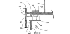
- FIG. 10 is a longitudinal cross-sectional view which shows the principal part of the left side part of the state to which the rice cooking part 1 and the induction heating cooking part 2 overlapped.
- the reed switch 18 is fixed on a dedicated circuit board or mounting plate 18A.
- the mounting plate 18A is fixed to the upper surface of the partition wall 61 (the front arc portion 61C).
- the reed switch 18 is disposed at the uppermost inside of the upper lid 2B.
- a gap G1 having a width W2 of about several mm to 20 mm is secured.
- the reed switch 18 is installed on the upper right side of the partition wall 61 through which the cooling air CF from the cooling fan 60 (see FIG. 10) passes, the temperature of the atmosphere around the reed switch 18 is also kept low. Be In addition, since the permanent magnet 19 is also disposed at a position where the high heat of the inner hook 13 is unlikely to be received, it is possible to reliably perform an operation in which the reed switch 18 senses the approach of the permanent magnet 19. The permanent magnet 19 turns the reed switch 18 ON only when the rice cooking unit 1 is placed directly above the induction heating and cooking unit 2.
- the control unit 23 senses the on operation. Then, the control unit 23 determines that the rice cooking unit 1 is placed at the regular position, and permits input of the rice cooking operation in the rice cooking unit 1. That is, unless the reed switch 18 is turned on, the input of the first input operation unit 15 of the rice cooking unit 1 is invalidated, and the rice cooking operation of the control unit 40 can not be started.
- the permanent magnet 19 is disposed at a position immediately above the reed switch 18 when the rice cooking unit 1 is placed on the induction heating cooking unit 2.
- a fixing plate 31 is provided on the upper surface of the lower frame 10B. The fixing plate 31 fixes the permanent magnet 19 to the upper surface of the lower frame 10B.
- the fixing plate 31 is formed of a material having a lower thermal conductivity than iron or aluminum, for example, a heat-resistant rubber.
- the permanent magnet 19 is installed at a distance W1 away from the heat shielding shield plate 93 surrounding the periphery of the bottomed cylindrical inner caul 13 with a space therebetween. Thereby, the permanent magnet 19 is prevented from being repeatedly heated and deteriorated in long-term use.
- the shielding plate 93 is the same as that in the first embodiment from which the bottom surface of the container 17 is removed. In other words, the shielding plate 93 and the container 17 have the same function to make it difficult to transfer the heat of the inner caul 13 to the permanent magnet 19, and the container 17 may be provided instead of the shielding plate 93.
- rice cooker 100 according to the second embodiment shown in FIGS. 8 to 10 has the following configuration. That is, Box-shaped induction heating cooking unit 2 provided with a top plate 20, an induction heating coil 24 disposed below the top plate 20, and a second input operation unit 22 for inputting heating conditions of the induction heating coil 24
- the cooking unit 1 includes an inner pot 13 heated by the induction heating coil 24 and a first input operation unit 15 for inputting cooking conditions.
- the rice cooking part 1 is heated by the drive of the induction heating coil 24 in the state placed on the top plate 20 of the induction heating cooking part 2, Inside the induction heating cooking unit 2, a cooling fan 60 for supplying a cooling air for cooling the induction heating coil 24, and control information for cooking between the induction heating cooking unit 2 and the rice cooking unit 1.
- the induction heating and cooking unit 2 has an outer shell formed by vertically overlapping a plastic upper lid 2B and a plastic lower case 2C having a size overlapping with the upper lid 2B.
- the top plate 20 is superimposed and fixed on the upper lid 2B,
- a partition wall 61 is integrally formed on the upper surface of the bottom portion of the lower case 2C, and the partition wall 61 divides the air flow path of the cooling fan 60 into the interior of the induction heating cooking section 2;
- the infrared signal transmitting / receiving unit 62 is supported by the partition wall 61, Furthermore, a support 74 that receives a load on the upper lid 2B side integrally with the lower case 2C is vertically provided.
- the infrared signal transmitting / receiving unit 62 since the infrared signal transmitting / receiving unit 62 is supported by the partition wall 61, the infrared signal transmitting / receiving unit 62 can be installed without increasing the number of attachment parts.
- the support 74 which receives the load on the upper lid 2B side integrally with the lower case 2C is provided, the mechanical strength of the outer shell case 2A of the induction heating cooking unit 2 is improved, and the rice cooking unit 1 is stable for a long time Can be expected to improve durability.
- the reed switch 18 is installed on the upper right side of the partition wall 61 through which the cooling air CF (see FIG. 10) from the cooling fan 60 passes, The temperature of the atmosphere is also kept low.
- the permanent magnet 19 is also disposed at a position where the internal kettle 13 does not easily receive the high heat, an operation in which the reed switch 18 senses the approach of the magnet can be reliably performed.
- the permanent magnet 19 turns on the reed switch 18 only when the rice cooking unit 1 is placed directly above the induction heating and cooking unit 2, and the control unit 23 senses the on operation of the reed switch 18.
- the placement on the regular position is detected, and the input of the cooking operation in the cooking unit 1 is permitted. That is, unless the reed switch 18 is turned on, the input of the first input operation unit 15 of the rice cooking unit 1 is invalidated, and the rice cooking operation of the control unit 40 can not be started.
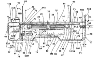
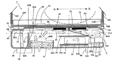
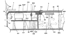
- FIG. 11 is a longitudinal cross-sectional view of rice cooker 100 according to the third embodiment.
- the rice cooking part 1 has shown only the lower end part.
- FIG. 12 is a main part longitudinal cross-sectional view of the left side portion of the rice cooker 100 of FIG.
- the descriptions of the same parts as in the first embodiment and the second embodiment may be omitted.
- the same or corresponding parts as in the first embodiment and the second embodiment are denoted by the same reference numerals.
- the rice cooker 100 which concerns on Embodiment 3 is devised so that the mechanical strength of the induction heating cooking part 2 which mounts the rice cooking part 1 may be strengthened, and the rice cooking part 1 can be stably mounted.
- the induction heating and cooking unit 2 includes a cooling fan 60, an induction heating coil 24, a power transmission coil 50 (not shown), a partition wall 61, and a control unit 23 (not shown) in the internal space of the induction heating and cooking unit 2. , A second input operation unit 22 (not shown), and an infrared signal transmitting / receiving unit 62.
- the induction heating coil 24 is formed in a disk shape.
- the partition wall 61 forms a first air passage SH1 and a second air passage SH2 in the internal space of the induction heating and cooking unit 2.
- the infrared signal transmitting / receiving unit 62 constitutes an infrared communication unit.
- the induction heating coil 24 is disposed on a heat resistant plastic support frame 63.
- the support frame 63 is formed with a large number of through holes (not shown) having a large opening area in order to increase air permeability.
- the induction heating and cooking unit 2 includes an outer shell case 2A including a bottomed box-shaped lower case 2C forming the outer shell and an upper lid 2B covering the entire upper surface of the lower case 2C.
- the lower case 2C and the upper lid 2B are formed by integral molding of plastic. Therefore, the material is a thermoplastic plastic.
- the lower case 2C and the upper lid 2B are shaped so as to completely overlap each other in plan view. In other words, the projected area when projecting up and down is the same. Further, since the upper lid 2B is used in a higher temperature environment than the lower case 2C, a material having higher heat resistance than the lower case 2C is selected.
- the planar dimension of the lower frame 10B is close to the planar shape of the upper lid 2B.
- the external shape of the entire rice cooker 100 is a box shape whose planar shape is close to a square, as in the first embodiment shown in FIG.
- a convex portion 2D which is a screw seat integrally formed at a predetermined interval is provided inside the lower case 2C.
- the thickness of the convex portion 2D is configured to be several times larger than the thickness T1 of the wall of the lower case 2C, so the upper lid 2B can be fixed to the convex portion 2D by the screw 64.
- a metal fixing plate 65 fixed to the lower surface of the upper lid 2B by adhesion or the like is provided. The screws 64 pass through the fixing plate 65 and are screwed to the convex portion 2D. In this manner, the upper lid 2B is securely fixed to the lower case 2C, and the outer shell case 2A of the induction heating and cooking unit 2 is formed.
- a bottom plate 66 is closely fitted in a large circular hole 16 formed in the central portion of the lower frame 10B.
- the bottom plate 66 is formed of a highly heat resistant plastic material such as PET or PPS.
- PET polyethylene styrene
- PPS polyphenylene sulfide
- the bottom plate 66 has a diameter larger than the maximum outside diameter dimension of the induction heating coil 24 and is located directly above the induction heating coil 24.
- the flat top plate 20 is attached to the upper surface so as to cover most of the upper lid 2B except for the front end and the rear end, and is formed of heat-resistant crystallized glass or plastic plate There is. Then, when the rice cooker 1 is placed on the induction heating cooker 2, the upper surface of the top plate 20 and the bottom plate 66 are in close contact with each other with a slight gap therebetween.
- the dimension H1 indicates the height (range) that can be recognized as the upper lid 2B on the appearance of the induction heating and cooking unit 2.
- the dimension H2 indicates the height (range) that can be recognized as the lower frame 10B on the appearance of the induction heating and cooking unit 2.
- the dimension H3 indicates the range of the upper case 10C.
- the second separation line (horizontal line PL2) shown in FIG. 11 is where the boundary between the upper cover 2B and the lower case 2C can be recognized on the appearance of the induction heating and cooking unit 2.
- the second separation line (horizontal line PL2) when manufacturing the outer shell of the induction heating cooking part 2, the lower case 2C and the upper lid 2B are overlapped.
- a cylindrical mounting seat 70 is provided on the lower surface of the upper lid 2B, and is integrally formed on the lower surface of the upper lid 2B. At least two front and rear positions of the support frame 63 are fixed to the mounting seat 70 by screws 71.
- a magnetic shield plate 72 is provided on the support frame 63. The magnetic shield plate 72 is disposed on the support frame 63 so as to cover the entire periphery of the induction heating coil 24.
- a convex portion 73 integrally formed on the lower surface of the upper lid 2B is provided on the lower surface of the upper lid 2B.
- a post 74 integrally formed on the upper surface of the lower case 2C is provided on the upper surface of the lower case 2C.
- the columns 74 and the projections 73 are formed at a plurality of locations in the rice cooking portion 1 so as to always face each other.
- the support column 74 is formed around the induction heating coil 24 avoiding the position of the induction heating coil 24.
- the support 74 and the convex part 73 face each other with a contact or a minute gap. Therefore, the load applied to the upper surface of the upper lid 2B can be expected to be supported by the support 74.
- the partition wall 61 divides the space enclosed by the lower case 2C and the upper lid 2B into the front and back as shown in FIG. At the upper end of the partition wall 61, a notch 61A is formed.
- a protrusion 75 integrally formed on the lower surface of the upper lid 2B is provided. Between the protrusion 75 and the uppermost surface of the partition wall 61, a cushioning material 76 such as elastic rubber is interposed.
- the infrared signal transmission / reception unit 62 includes an infrared communication element 62A, a support substrate 62B, and a communication control unit 62C.
- the support substrate 62 ⁇ / b> B is horizontally supported on the front side surface of the partition wall 61.
- the notch 61A is formed at a position facing the infrared communication element 62A.
- a cooling fan 60 constituted by an axial flow fan is disposed in close proximity to the intake port 77 formed on the front bottom wall of the lower case 2C.
- the intake port 77 is composed of a large number of narrow slit-like or small-diameter holes.
- the fan motor 60M is installed immediately above the air inlet 77, and the cooling fan 60 is rotationally driven by the fan motor 60M.
- the fan motor 60M is fixed to the upper surface of a support leg 78 having an inverted U-shaped vertical cross section, which is integrally formed with the lower case 2C so as to straddle the upper side of the air inlet 77.
- the auxiliary air intake port 79 is composed of a large number of narrow slit-like or small-diameter holes.
- the concave portion 116 is formed with a tunnel-like space so that the user can insert the fingertips of both hands when transporting the induction heating and cooking unit 2 alone and when transporting while the rice cooking unit 1 is placed.
- the auxiliary air intake port 79 is formed in a curved wall surface portion of the lower case 2 ⁇ / b> C forming the concave portion 116. As a result, two routes for the intake path to the cooling fan 60 are secured. That is, the first intake passage from the intake port 77 at the bottom surface of the lower case 2C, and the second intake path from the auxiliary intake port 79 adjacent to the intake port 77 and formed on the inclined surface.
- the heating circuit board 80 mounts the inverter circuit which supplies high frequency electric power with respect to the induction heating coil 24, and various electric components are mounted.
- a support plate 82 for supporting the heating circuit board 80 is provided on the bottom surface of the lower case 2C.
- a plurality of support plates 82 are provided on the bottom surface of the lower case 2C.
- An electrically insulating sheet 83 (or a thin plate) is provided immediately above the heat dissipating fins 81.
- the electrically insulating sheet 83 is horizontally disposed directly above the heat radiation fins 81.
- the electrically insulating sheet 83 (or thin plate) is made of a material such as PP or PET.
- thick solid arrows indicate the flow of the cooling air CF supplied from the cooling fan 60. Also, thick dashed arrows indicate the intake flow introduced into the cooling fan 60.
- an arrow LL indicates the line of sight of the user or the like from the position YE of the eye.
- the front ends of the heating circuit board 80 and the support plate 82 can not be viewed directly through the auxiliary air inlet 79. For this reason, not only the appearance of beauty but also insertion of chopsticks or other foreign matter (metal rod) used for food is blocked by the auxiliary air intake port 79, and the tip thereof temporarily enters the lower case 2C. Also, it does not reach the heating circuit board 80, and the electrical safety is high.
- the heating circuit board 80 can not be viewed directly through the auxiliary air intake port 79.
- a plurality of exhaust ports 108 for discharging the cooling air from the cooling fan 60 are formed side by side on the rear rear wall of the lower case 2C.
- the partition wall 61 divides the internal space of the induction heating and cooking unit 2 into a space with the cooling fan 60 and a space with the infrared signal transmitting / receiving unit 62, as shown in FIG. That is, with the partition wall 61 as a boundary, the second air flow path SH2 is formed in the front, and the first air flow path SH1 is formed in the rear.
- the projection 75 is formed when the upper lid 2B is formed, and the partition wall 61 is formed when the lower case 2C is formed, it can be manufactured more easily than forming a column or wall having a large height. Also, it is advantageous in cost.
- the partition wall 61 may be formed to extend to the lower surface of the upper lid 2B.
- the temperature sensor 25 is a contact type temperature sensor that contacts the back surface (bottom surface) of the upper lid 2B to measure the temperature of the top plate 20, and a thermistor type temperature detection element is used. Temperature measurement data of the temperature sensor 25 is transmitted to a temperature detection circuit 104 (not shown) by a signal line 105 (not shown), and information on the temperature grasped by the temperature detection circuit 104 is transmitted to the control unit 23 Ru.
- the thermistor (temperature detection element) is installed so as to penetrate the central portion (hollow portion) of the induction heating coil 24 having a hollow annular shape in plan view as shown in the drawing.
- An alternate long and short dash line CL indicates the vertical center line of the induction heating coil 24 and also coincides with the vertical center line of the temperature sensor 25.
- the internal space of the induction heating and cooking unit 2 is divided back and forth at the rear portion of the second input operation unit 22 by the partition wall 61. Then, electrical components such as switches opened and closed by the input button 22A and the input button 22A of the second input operation unit 22 are in the state of being present in the second air passage SH2. Therefore, the temperature rise of the second input operation unit 22 is suppressed.
- the amount of cooling air supplied from the cooling fan 60 via the notch 61A may be much smaller than the amount of cooling air supplied to the induction heating coil 24 side.
- the notch 61A may not be provided, and the space may not communicate with the first air passage SH1. That is, the portion of the second input operation unit 22 and the infrared signal transmitting / receiving unit 62 may not necessarily be cooled by air.
- the second window 91 doubles as a window for transmitting the infrared signal from the infrared signal transmitting / receiving unit 62 and a window for transmitting the infrared signal from the infrared signal transmitting / receiving unit 41.
- the second window 91 is formed at the front end of the upper lid 2B in which the induction heating and cooking unit 2 and the rice cooking unit 1 are vertically overlapped and in proximity or in contact with each other.
- the second window 91 is covered by an infrared ray transmitting glass or plastic plate.
- a first window 90 formed in the lower frame 10B is provided.
- the first window 90 also has the same function and structure as the second window 91, and is formed of the same material.
- two or more infrared communication elements 62A are provided instead of one, at least one for infrared signal transmission, and at least one other for infrared signal reception. In such a case, it is advantageous in terms of structure that the second windows 91 described later can be shared if they are arranged side by side in the approach state.
- the rice cooker 1 also includes an infrared light emitting element 41A, a support substrate 41B, and a communication control unit 41C.
- a shielding plate 93 for heat shielding is provided around the bottomed cylindrical inner pot 13 so as to surround the bottomed cylindrical inner pot 13 at intervals.
- the shielding plate 93 has a cylindrical shape whose upper and lower portions are open, and is placed on the lower frame 10B. Due to the shielding plate 93 for heat shielding, the installation space of the infrared signal transmitting / receiving unit 41 and the installation space of the inner caul 13 become two independent spaces in which air and steam do not flow. For this reason, it is possible to prevent the infrared signal transmitting / receiving unit 41 from being excessively heated by the influence of the high heat of the inner pot 13 to shorten the life or to cause the performance deterioration or the malfunction.
- the weight sensor 95 has the same configuration as that of the second embodiment. Further, a weight measurement signal indicating the measurement result of the weight sensor 95 is input to the control unit 23, and transmitted from the control unit 23 to the infrared signal transmission / reception unit 41 by the infrared signal transmission / reception unit 62. As described above, as in the second embodiment, the weight measurement signal received by the infrared signal transmission / reception unit 41 is input to the control unit 40 of the rice cooking unit 1 and used to determine the heating program (thermal power or energization time etc.) Be done.
- the reed switch 18 is a magnetic proximity switch that receives a magnetic force and closes an electrical contact.
- a permanent magnet 19 is provided at the bottom of the rice cooker 1.
- the induction heating and cooking unit 2 includes the cooling fan 60, the induction heating coil 24, the power transmission coil 50 (not shown), the partition wall 61, the control unit 23, and the infrared signal transmitting / receiving unit 62 and built-in.
- the induction heating coil 24 is formed in a disk shape.
- the partition wall 61 forms a first air passage SH1 and a second air passage SH2 in the internal space of the induction heating and cooking unit 2.
- the infrared signal transmitting / receiving unit 62 constitutes an infrared communication unit.
- the induction heating coil 24 is installed on a support frame 63 called a coil base formed of heat resistant plastic or the like.
- a support frame 63 a large number of through holes 63A having a large opening area are formed in order to increase air permeability.
- the induction heating and cooking unit 2 is configured of an outer shell case 2A by a bottomed box-shaped lower case 2C constituting the outer shell of the induction heating and cooking unit 2 and an upper lid 2B covering the entire upper surface of the lower case 2C. ing.
- the lower surface of the upper lid 2B is provided with the protrusion 75 integrally formed on the lower surface of the upper lid 2B.
- a mounting plate 18A extending horizontally is fixed between the projection 75 and the uppermost surface of the partition wall 61. In other words, the mounting plate 18A is held against the upper surface of the partition wall 61 by the projection 75.
- a gap G2 formed with a width W3 on the left side of the partition wall 61 is isolated from the first air passage SH1.
- it is in communication with the second air blowing passage SH2, and a part of the cooling air introduced below the second input operation unit 22 reaches the air gap G2. That is, since the partition wall 61 is also used to support the reed switch 18, the number of parts can be reduced.
- the ambient temperature of the installation space of the permanent magnet 19 and the reed switch 18 does not increase, so the permanent magnet 19 and the reed switch 18 are not deteriorated by long-term use, and the safety is improved. Can be expected.
- the external air flows from the air intake port 77 and the auxiliary air intake port 79 as indicated by thick thick arrows by the operation of the cooling fan 60. It is sucked.
- the cooling air introduced into the second air passage SH2 from the notch portion 61A cools various electric components inside the second air passage SH2, for example, the infrared communication element 62A of the infrared signal transmitting / receiving unit 62 And an exhaust port different from the exhaust port 108 (not shown). Alternatively, it is attracted by the cooling air introduced into the first air passage SH1 and discharged from the same exhaust port 108 to the outside.
- the third embodiment has various characteristic configurations, and therefore, effects as described below can also be expected.
- Part 1 Inside the induction heating cooking unit 2, a cooling fan 60 for supplying a cooling air for cooling the induction heating coil 24, and control information for cooking between the induction heating cooking unit 2 and the rice cooking unit 1.
- the induction heating and cooking unit 2 includes an outer shell case formed in a box shape by a plastic upper lid 2B and a plastic lower case 2C having a size overlapping with the upper lid 2B, The top plate 20 is superimposed and fixed on the upper lid 2B, A first support (mounting seat 70) for holding the induction heating coil 24 is integrally formed on the lower surface of the upper lid 2B, A partition wall 61 is integrally formed on the upper surface of the bottom portion of the lower case 2C and extends upward at the side of the intake port 77 of the cooling fan 60, and a heat insulating material is formed between the upper end of the partition wall 61 and the lower surface of the upper lid 2B.
- Cushion material 76 is
- the air tightness between the upper end of the partition wall 61 and the lower surface of the upper lid 2B is improved, and unnecessary air from the cooling fan 60 side to the space on the opposite side of the cooling fan 60 across the partition wall 61. Can be prevented.
- the cushion material 76 receives the load of the upper lid 2B, the impact on the upper end portion of the partition wall 61 can be alleviated, and the breakage thereof can be prevented.
- Part 2 A heating circuit board 80 including an inverter circuit or the like is disposed at a position directly below the induction heating coil 24, and the induction heating coil 24 and the heating circuit board 80 are simultaneously operated by the cooling fan 60 from the side of the induction heating coil 24. Cooling air is supplied in parallel. Therefore, a cooling air passage (first air passage SH1) having the cooling fan 60 upstream is formed and disposed inside the induction heating and cooking unit 2, and a straight flow toward the exhaust port 108 can be formed. Thereby, it can be expected that the cooling performance of the internal space of the induction heating and cooking unit 2 can be improved.
- Part 3 At least the infrared communication element 62 ⁇ / b> A of the infrared signal transmitting / receiving unit 62 is mounted on a support substrate 62 ⁇ / b> B supported by the partition wall 61. Therefore, since the infrared communication element 62A is supported using the partition wall 61, the structure can be simplified, which is advantageous in terms of manufacturing cost.
- the member constituting the shell case 2A of the induction heating cooking section 2 is configured by the plastic upper lid 2B and the plastic bottomed box-shaped lower case 2C having a size overlapping with the upper lid 2B. It is. Therefore, by forming the upper lid 2B and the lower case 2C by integral molding of plastic and combining the upper lid 2B and the lower case 2C, the box-shaped outer shell case 2A can be easily manufactured.
- the member constituting the shell case 2A of the induction heating cooking section 2 is configured by the plastic upper lid 2B and the plastic bottomed box-shaped lower case 2C having a size overlapping with the upper lid 2B. It is. Since a mounting seat 70 for supporting a coil base (support frame 63) made of heat resistant plastic for supporting the induction heating coil 24 is formed by integral molding on the lower surface of the upper lid 2B, the structure member for supporting the induction heating coil 24 The number of points can be reduced, which is advantageous in terms of manufacturing cost.
- a second window 91 for transmitting an infrared signal for the infrared signal transmitting / receiving unit 62 is formed in a part of the upper lid 2B where the induction heating cooking unit 2 and the rice cooking unit 1 overlap and are in proximity or in contact with each other There is. Moreover, since the second window 91 is covered from above by the rice cooking unit 1 when the rice cooking unit 1 is used, unnecessary light does not enter the second window 91 as disturbance light, and the rice cooking unit 1 is used. It can be expected that infrared communication between the and the induction heating and cooking unit 2 can be reliably performed.
- Part 7 The heating area by the induction heating coil 24 is avoided, and at least two places around the induction heating coil 24 are formed struts 74 integrally extending upward from the upper surface of the lower case 2C.
- the post 74 receives a load from the upper lid 2B side. In other words, when the rice cooking unit 1 is placed, it is possible to prevent the top plate 20 that receives the weight from bending downward. For this reason, since the positional relationship between the rice cooking part 1 and the induction heating cooking part 2 is stabilized over a long period of time, the rice cooking operation can be performed safely.
- Part 8 As shown in FIG. 12, since the reed switch 18 that operates by sensing the presence of the permanent magnet 19 of the rice cooking unit 1 is installed on the partition wall 61, the partition wall 61 is also used to support the reed switch 18. Therefore, the number of parts can be reduced and the manufacturing cost can be reduced. Furthermore, since the reed switch 18 is disposed in the gap G2 partitioned by the partition wall 61, the ambient temperature of the installation space of the reed switch 18 does not become high, and it can be expected to achieve a long life.
- the cooking unit includes: a rice cooking unit 1 for accommodating the food to be cooked therein; and an induction heating and cooking unit 2 for heating and cooking the rice cooking unit 1 on an upper surface thereof;
- the rice cooker 1 includes an upper case 10C forming an outer shell, and an annular lower frame 10B formed of a heat resistant material provided below the lower end face of the upper case 10C.
- the induction heating and cooking unit 2 includes an upper lid 2B made of a heat-resistant material provided with a top plate 20 on which the rice cooker 1 is placed, and a lower case 2C having a bottom whose upper surface opening is closed by the upper lid 2B. Between the upper lid 2B and the lower case 2C, at least one of a column 74 and a partition wall 61 integrally formed with at least one of the upper lid 2B and the lower case 2C is provided.
- the mechanical strength of the induction heating and cooking unit 2 on which the rice cooking unit 1 is placed, that is, the load resistance in the vertical direction is enhanced, and the induction heating and cooking unit 2 stabilizes the rice cooking unit 1. It is possible to carry out induction heating while supporting it and expect stable cooking operation.
- FIG. 13 is an enlarged vertical cross-sectional view of the front portion of rice cooker 100 according to the fourth embodiment.
- the descriptions of the same parts as the first to third embodiments may be omitted.
- the same or corresponding parts as in Embodiments 1 to 3 are denoted by the same reference numerals.
- the rice cooker 100 which concerns on Embodiment 4 changes the installation position of the infrared signal transmission / reception part 62. As shown in FIG.
- the second window 91 is formed in the upper lid 2B, and is provided to transmit an infrared signal.
- the lower frame 10B made of heat-resistant plastic constitutes the bottom of the rice cooker 1 and forms a first window 90 for transmitting an infrared signal.
- the support substrate 62B supports the infrared communication element 62A of the infrared signal transmitting / receiving unit 62.
- the left end portion of the support substrate 62B is connected to the partition wall 61, and the support substrate 62B is horizontally supported.
- the range 22W in the front-rear direction of the second input operation unit 22 is as indicated by a solid arrow. This will be discussed in more detail later.
- input buttons 22A of a plurality of push-type electronic switches 97 are arranged in a row at regular intervals.
- the plastic pressing rod 97A is moved downward to close the internal contact of the electronic switch 97 and generate a signal.
- the circuit board 98 mounts each electronic switch 97.
- the protective sheet 99 (or the protective plate) is formed of a thin and flexible plastic material, and covers the top of the input button 22A in a sealed state, to prevent the infiltration of water from above.
- the input button 22A moves downward by a minute dimension to close the internal contact of the electronic switch 97.
- a through hole 101 is formed in the plastic support frame 102.
- the through hole 101 has an aperture larger than the external dimensions of the input button 22A so as to allow the vertical movement of the input button 22A.
- the second input operation unit 22 is provided with a second display unit 28 (not shown) that displays an operation input result of the second input operation unit 22.
- the second display unit 28 includes a liquid crystal display screen, a light emitting diode (LED), and the like.
- the LED illuminates the protective sheet 99 of the second input operation unit 22 with light from below to display a specific part of the protective sheet 99 in red or yellow, and displays the input result of each electronic switch 97 to the user Do.
- the liquid crystal display screen is configured such that an opening (not shown) is provided in a part of the protective sheet 99, the opening is covered from above with a transparent sheet, and the liquid crystal display screen is exposed to the opening. .
- the input function of the second input operation unit 22 valid or invalid.
- the display function of the second display unit 28 is simultaneously invalidated, and the screen display is extinguished.
- the input function of the second input operation unit 22 is enabled (when activated for the first time, when the invalidation is canceled)
- the display function of the second display unit 28 is also enabled simultaneously. And the display operation is performed.
- the control unit 23 detects that the rice cooking unit 1 has been placed
- the input function of the second input operation unit 22 is invalidated.
- the reed switch 18 described in the second and third embodiments is an example of means for detecting that the rice cooker 1 has been placed.
- a wall surface opening 30 is formed at the lower end of the rice cooker 1.
- the protruding portion 103 (convex line) is configured to narrow the facing distance S between the lower frame 10B constituting the bottom surface of the rice cooking portion 1 and the upper surface of the second input operation portion 22.
- the protrusion 103 suppresses the flow of the heat generated at the position immediately above the induction heating coil 24 located rearward of the protrusion 103 over the protrusion 103 to the second input operation unit 22 side. For this reason, even if the bottom surface of the rice cooking part 1 becomes high temperature by the induction heating coil 24 when performing a rice cooking operation, it is suppressed that the part of 2nd input operation part 22 will be in an overheated state.
- the portion of the second input operation unit 22 becomes hot, and another heating by the induction heating cooking unit 2 alone is immediately performed. It does not lead to situations where cooking can not be started.
- a range 22 W indicates the width in the front-rear direction of the second input operation unit 22 and is about 50 mm to 70 mm.
- the upper lid 2 ⁇ / b> B extends downward at a constant distance at the lower end edge of the entire periphery, and the skirt portion 2 ⁇ / b> BU is integrally formed.
- the foot 2BU plays a role of fitting into the upper edge of the lower case 2C as shown in FIG. For this reason, in the polymerization state of the lower case 2C and the upper cover 2B, the upper cover 2B is tightly fitted to the lower case 2C and does not move in the back and forth direction or the left-right direction carelessly. Therefore, as a result, the strength of the shell case 2A of the induction heating unit 2 can be improved by a simple structure.
- Rice cooker 100 shown in the fourth embodiment is provided with projection 103 (convex line) on the upper surface of upper lid 2B, and lower frame 10B constituting the bottom surface of rice cooker 1, and the upper surface of second input operation unit 22. And the facing distance S with each other is narrowed. For this reason, there is an effect that the heat generated at the position right above the induction heating coil 24 located behind the protrusion 103 is prevented from flowing over the protrusion 103 and flowing to the second input operation unit 22 side. .
- FIG. 14 is a plan view showing the induction heating and cooking unit 2 of the rice cooker 100 according to the fifth embodiment.
- FIG. 15 is a longitudinal sectional view taken along line X2-X2 of FIG. In FIG. 15, the rice cooking part 1 has shown only the lower end part.
- the descriptions of the same parts as in the first to fourth embodiments may be omitted.
- the same or corresponding parts as in the first to fourth embodiments are denoted by the same reference numerals.
- the rice cooker 100 which concerns on Embodiment 5 changes the installation position of the infrared rays signal transmission / reception part 62. As shown in FIG. Further, it is characterized in that the installation position of the power transmission coil 50 is set on the upstream side of the first air passage SH1 through which the cooling air of the cooling fan 60 flows as much as possible.
- the inside extends at a predetermined distance in the upper direction at the upper end edge of the entire periphery to integrally form the stepped portion 10BT.
- the stepped portion 10BT plays the role of fitting into the lower end edge of the upper case 10C as shown in FIG. For this reason, in the polymerization state of the upper case 10C and the lower frame 10B, the upper case 10C is closely fitted to the outer peripheral edge portion of the lower frame 10B, and does not move carelessly in the back and forth or left-right direction. Accordingly, as a result, the strength of the shell case 2A of the rice cooker 1 can be improved by a simple structure.
- the entire surface of the second input operation unit 22 is covered with a surface plate 22P such as a glass plate.
- a touch-type input method using the surface plate 22P is adopted, and when the user touches a specific position on the surface plate 22P with a finger or the like, the touch operation is sensed and the control unit 23 is notified. It is possible to input.
- a capacitive touch switch is used.
- the detection unit 22S is configured to sense a touch operation with a finger or the like, and transmit a signal corresponding to the position touched by the finger to the control unit 23.
- a large square opening 2H is formed in the central portion of the upper lid 2B.
- the top of the opening 2H is covered with a top plate 20 formed of crystallized glass, heat resistant plastic or the like.
- a contact-type temperature sensor 25 that contacts the back surface of the top plate 20 and measures the temperature is provided on the back surface (bottom surface) of the top plate 20.
- a thermistor is used as the temperature sensor 25.
- the temperature detection circuit 104 is configured to receive temperature data measured by the temperature sensor 25, and is connected to the temperature sensor 25 by a signal line 105. As shown in FIG. 15, the temperature sensor 25 is installed so as to penetrate the central portion (hollow portion) of the hollow annular induction heating coil 24.
- the temperature data detected by the temperature detection circuit 104 is transmitted to a control unit 23 mainly configured of a microcomputer.
- the temperature detection circuit 104 and the control unit 23 are mounted on the control circuit board 106.
- the control circuit board 106 is fixed at a predetermined position by a support convex portion 115 which is integrally formed so as to protrude integrally from the bottom surface of the lower case 2C.
- the support convex portion 114 is formed in the same manner as the support convex portion 115, and supports the heating circuit board 80.
- the temperature detection circuit 104 and the control unit 23 appear to be near the rear side of the radiation fin 81, but in reality, the temperature detection circuit 104 and the control unit 23 are not directly behind the radiation fin 81. There is. However, it is desirable from the viewpoint of cooling performance to provide the first air blowing passage SH1 at a position just before the exhaust port 108 described later.
- a plurality of exhaust ports 108 are formed in the rear surface (rear wall) of the lower case 2C.
- the exhaust port 108 is formed of a narrow slit-like hole or a large number of small-diameter holes so that foreign matter does not enter the lower case 2C.
- a cooling fan 60 such as an axial flow fan is installed immediately above the air inlet 77 so that the rotation axis of the cooling fan 60 is vertical.
- a fan motor 60M is fixed on an elongated support located at the center of the fan case 60C.
- the second separation line (horizontal line PL2) is a position at which the lower case 2C and the upper lid 2B constituting the outer shell case 2A of the induction heating cooking unit 2 overlap.
- the post 74 and the partition wall 61 are integrally formed from the bottom surface of the lower case 2C up to the height (position) of the second separation line. Therefore, when the lower case 2C is formed of a thermoplastic material (plastic), it can be easily matched with the height of the lower case 2C. Therefore, the formation of the columns 74 and the partition walls 61 can be facilitated in the manufacturing process.
- the support column 74 and the partition wall 61 are aligned with the height of the second separation line, and there is no part projecting upward than the second separation line (horizontal line PL2). Therefore, there is also an advantage that it is possible to easily perform an operation of stacking or moving a person or a machine during transportation or storage at a manufacturing site.
- the reed switch 18 in FIG. 14 is a magnetic proximity switch that receives a magnetic force and closes an electrical contact.
- the reed switch 18 is supported by the right side surface of the front arc portion 61C that constitutes a part of the partition wall 61.
- the space where the reed switch 18 is installed is the outside of the first air passage SH1 of the cooling fan 60 and is a place not actively cooled, but at a position far from the induction heating coil 24 and the bottom plate 66 of the rice cooking portion 1 is there. Therefore, there is no concern that the space in which the reed switch 18 is installed is heated by the heat generated by the induction heating coil 24 and the bottom plate 66 of the rice cooker 1.
- the top plate 20 formed of an infrared transmitting material is not provided without providing the second window 91 dedicated to the infrared signal transmitting / receiving unit 41 and the infrared signal transmitting / receiving unit 62. It is used to perform infrared communication. Therefore, processing for providing the second window 91 and parts such as an infrared transmitting plate covering the second window 91 are also unnecessary, which is advantageous in terms of manufacturing cost.
- the cooling air from the cooling fan 60 is forcibly introduced into the space where the infrared signal transmitting / receiving unit 62 is installed. Moreover, in the fifth embodiment, the cooling air is cooled by a cooling air different from the cooling air flowing around the induction heating coil 24 that generates the highest temperature and the power transmission coil 50 that generates heat. Therefore, the infrared signal transmitting / receiving unit 62 receives heat from the induction heating coil 24 and the power transmission coil 50 and is not heated to such a temperature as to cause performance deterioration or the like. Further, the reed switch 18 is in a space opposite to the induction heating coil 24 with the partition wall 61 interposed therebetween. For this reason, the reed switch 18 is located apart from the induction heating coil 24 and is not heated by the induction heating coil 24.
- the wall surface opening 30 has a shape formed by notching the bottom wall 10P of the lower frame 10B, and a plurality of the wall openings 30 are spaced along the entire circumference of the lower frame 10B (shown example 12) are formed.
- the wall surface opening 30 has an effect of dissipating the heat of the bottom surface of the heated rice cooking section 1 to the outside.
- Rice cooker 100 shown in the fifth embodiment is: An induction heating cooking unit 2 including a top plate 20, an induction heating coil 24 disposed below the top plate 20, and a second input operation unit 22 for inputting heating conditions of the induction heating coil 24;
- the rice cooker 1 is provided with an inner pot 13 which accommodates food to be cooked and is heated by the induction heating coil 24, and a first input operation unit 15 for inputting rice cooking conditions;
- the rice cooking part 1 is heated by the drive of the induction heating coil 24 in the state placed on the top plate 20 of the induction heating cooking part 2, Inside the induction heating cooking unit 2, a cooling fan 60 for supplying a cooling air for cooling the induction heating coil 24, and control information for cooking between the induction heating cooking unit 2 and the rice cooking unit 1.
- the induction heating and cooking unit 2 includes an outer shell case 2A configured in a box shape by a plastic upper lid 2B and a plastic lower case 2C having a size overlapping with the upper lid 2B, The top plate 20 is superimposed and fixed on the upper lid 2B, On the upper surface of the bottom of the lower case 2C, a column 74 is formed so as to vertically rise so that the top of the lower case 2C reaches the upper lid 2B.
- the mechanical strength of the induction heating and cooking unit 2 on which the rice cooking unit 1 is placed, that is, the load resistance in the vertical direction is enhanced, and the induction heating and cooking unit 2 stabilizes the rice cooking unit 1. It is possible to carry out induction heating while supporting it and expect stable cooking operation.
- FIG. 16 is a longitudinal cross-sectional view showing a front half of induction heating and cooking unit 2 in rice cooker 100 according to the sixth embodiment.
- the descriptions of the same parts as the first to fifth embodiments may be omitted.
- the same or corresponding parts as in the first to fifth embodiments are denoted by the same reference numerals.
- Rice cooker 100 is characterized in that the air intake path of cooling fan 60 is changed, and external air is introduced from air intake port 177 provided on the front surface of lower case 2C. Further, it is also characterized in that the infrared signal transmitting / receiving unit 62 is provided in the first intake passage KU instead of being provided in the first air passage SH1.
- An intake port 177 is formed on the front surface of the lower case 2C. Similar to the intake port 77 shown in the first to fifth embodiments, the intake port 177 is formed with a plurality of thin slit-like or fine through holes adjacent to each other. At the front edge of the top plate 20, a heat-resistant sealing material 110 such as silicone rubber is provided. The sealing material 110 has a cross-sectional shape that sandwiches the front edge of the top plate 20 from above and below.
- the top plate 20 is supported from below by a support 74 via a sealing material 110. That is, the convex portion 73 integrally formed on the lower surface of the upper lid 2B abuts on the uppermost surface of the column 74 directly below the convex portion 73, and is supported by the column 74 from below. Therefore, even if the user frequently presses the surface plate 22P for touch-type input operation of the second input operation unit 22, the upper cover 2B is curved downward because the upper cover 2B is held by the support 74. Etc., and stable input operation can be performed over a long period of time.
- the infrared signal transmitting / receiving unit 62 is provided in the first intake passage KU linearly formed from the intake port 77 to the cooling fan 60, the cooling fan 60 cools the induction heating coil 24.
- the infrared signal transmitting and receiving unit 62 can be cooled by the cold air before it is cut.
- Parts such as the electronic circuit such as the touch type input detection unit 22S and the liquid crystal display screen constituting the second display unit 28 can also be cooled by the cooling air.
- the cooling fan 60 When heating the rice cooking unit 1, the cooling fan 60 is always operated to cool the induction heating coil 24, so that the infrared signal transmitting / receiving unit 62, the detection unit 22S, etc. are cooled by the cooling air during the rice cooking operation. It is continuously cooled.
- a support plate 111 of the circuit board 98 is provided in the lower case 2C.
- the support plate 111 is fixed at a specified position above the lower case 2C by a support column 117 formed in a columnar shape by integral molding from the bottom surface of the lower case 2C.
- a support leg 112 and a support leg 113 are provided on the upper surface of the support plate 111.
- the support legs 112 and the support legs 113 are formed of an electrically insulating material.
- Rice cooker 100 shown in the sixth embodiment is An induction heating cooking unit 2 including a top plate 20, an induction heating coil 24 disposed below the top plate 20, and a second input operation unit 22 for inputting heating conditions of the induction heating coil 24;
- the rice cooker 1 is provided with an inner pot 13 which accommodates food to be cooked and is heated by the induction heating coil 24, and a first input operation unit 15 for inputting rice cooking conditions;
- the rice cooking part 1 is heated by the drive of the induction heating coil 24 in the state placed on the top plate 20 of the induction heating cooking part 2, Inside the induction heating cooking unit 2, a cooling fan 60 for supplying a cooling air for cooling the induction heating coil 24, and control information for cooking between the induction heating cooking unit 2 and the rice cooking unit 1.
- the induction heating and cooking unit 2 includes an outer shell case 2A configured in a box shape by a plastic upper lid 2B and a plastic lower case 2C having a size overlapping with the upper lid 2B, The top plate 20 is superimposed and fixed on the upper lid 2B, On the upper surface of the bottom of the lower case 2C, a column 74 is formed so as to vertically rise so that the top of the lower case 2C reaches the upper lid 2B.
- the mechanical strength of the induction heating and cooking unit 2 on which the rice cooking unit 1 is placed, that is, the load resistance in the vertical direction is enhanced. Therefore, induction heating can be performed while the induction heating and cooking unit 2 stably supports the rice cooking unit 1, and a stable rice cooking operation can be expected.
- FIG. 17 is a longitudinal cross-sectional view showing the lower part of the rice cooking unit 1 and the induction heating and cooking unit 2 in the rice cooker 100 according to the seventh embodiment.
- the descriptions of the same parts as in the first to sixth embodiments may be omitted.
- the same or corresponding parts as in the first to sixth embodiments are denoted by the same reference numerals.
- the rice cooker 100 which concerns on Embodiment 7 improves the upper cover 2B of the induction heating cooking part 2, and lower case 2C.
- a step 2E is formed at the edge of the opening 2H.
- the stepped portion 2E is formed over the entire periphery (front and rear and left and right) of the opening edge of the opening 2H.
- the stepped portion 2E is formed thicker than the other portion of the upper lid 2B in order to increase the mechanical strength.
- the stepped portion 2E is integrally formed simultaneously with the injection molding of the upper lid 2B, and is formed such that the position of the second separation line (horizontal line PL2) is the lower limit.
- the partition wall 61 has a height dimension to be in contact with the lower surface of the step 2E as shown in FIG. In other words, the position of the second separation line (horizontal line PL2) is the upper limit position.
- the seal member 110 is formed of a material such as silicone rubber in order to protect the peripheral end face of the top plate 20 from impact and to prevent the infiltration of spilled water, cooking fluid and the like from the top surface of the top plate 20.
- the shoulder 2E indirectly supports the peripheral portion of the top plate 20 by supporting the sealing material 110.
- the step 2E and the sealing material 110 may be bonded by an adhesive in order to further fix the step.
- the partition wall 61 is formed with a plurality of through holes through which the external air sucked by the cooling fan 60 from the air inlet 77 passes. Arrows indicated by broken lines indicate the flow of air sucked by the cooling fan 60.
- the power transmission coil 50 for supplying power for the control unit 40 of the rice cooking unit 1 and the first display unit 42 is fixed on a support leg 119 formed closer to the cooling fan 60 than the partition wall 61.
- the support legs 119 are integrally formed from the bottom surface (bottom wall portion) of the lower case 2C when the lower case 2C is injection-molded.
- a mounting plate 120 that directly supports the power transmission coil 50 is provided on the upper surface of the partition wall 61.
- the mounting plate 120 is formed of an electrically insulating material. The mounting plate 120 is fixed to the upper surface of the partition wall 61 after the power transmission coil 50 is fixed.
- the infrared signal transmitting / receiving unit 62 is installed on a support substrate 62 B whose rear end is fixed to the partition wall 61.
- the support substrate 62 B is fixed on the support legs 118.
- the support legs 118 are integrally formed from the bottom surface of the lower case 2C at the time of injection molding of the lower case 2C.
- the infrared signal transmitting / receiving unit 62 is located upstream of the flow of the cold air flow to be sucked.
- a surface plate 122P is provided on the surface of the second input operation unit 22.
- the surface plate 122P is formed in a strip shape that is long in the left-right direction and covers the surface of the touch input type second input operation unit 22.
- the surface plate 122P is a thin plate formed of a heat resistant plastic material.
- the surface plate 122P is provided with a through hole 123 formed corresponding to the second window 91.
- the second input operation unit 22 and the infrared signal transmitting / receiving unit 62 are linearly arranged between the intake port 77 and the cooling fan 60. For this reason, even when induction heating is performed for the rice cooking unit 1 or when the induction heating / cooking unit 2 is operated as a single unit to perform cooking, the passage of air from the intake port 77 to the cooling fan 60 The second input operation unit 22 and the infrared signal transmitting / receiving unit 62 are efficiently cooled. Moreover, since a part of the air from the air inlet 77 to the cooling fan 60 passes around the power transmission coil 50 and then reaches the cooling fan 60, the power transmission coil 50 is also cooled at the same time.
- the rice cooker 1 is formed of an upper case 10C forming an outer shell, and an annular heat-resistant material provided below the upper case 10C. And a lower frame 10B.
- the lower frame 10B is provided with a bottom wall 10P protruding from the bottom toward the induction heating and cooking section 2 along the outer edge of the bottom.
- the lowermost end surface of the bottom wall 10P extends vertically to a position further below the second separation line (horizontal line PL2). For this reason, the lower part of the bottom wall 10P faces the front upper end of the lower case 2C beyond the upper lid 2B. Thereby, even if the rice cooking part 1 tries to move backward carelessly, the lower part of the bottom wall 10P hits the front of the lower case 2C, and the movement is blocked.
- the lowermost end face of the bottom wall 10P extends vertically to the lower side further than the second separation line (horizontal line PL2) at the rear of the lower frame 10B and at both the left and right as well. Unnecessary movement in the direction is prevented. For this reason, in the rice cooker 100 according to the seventh embodiment, when the rice cooking unit 1 is placed on the induction heating cooking unit 2, the advantage is that the mounting position of the rice cooking unit 1 is stabilized as in the first embodiment. There is.
- the upper surface of the top plate 20 and the lower surface of the lower frame 10B of the rice cooker 1 come into contact with each other or come close to each other with a minute gap.
- an air layer is provided between the lower side of the cooking unit 1 and the table or pedestal or the like. Is secured.
- the height in the vertical direction of the bottom wall 10P can be made larger than that in the first embodiment. Therefore, when the rice cooking unit 1 is placed on the upper surface of furniture or the like such as a table, the opposing distance between the rice cooking unit 1 and the furniture becomes large, and the volume of the air gap becomes large. Can be further reduced.
- the rice cooker 100 according to the seventh embodiment shown in FIG. 17 has the following configuration. That is, Box-shaped induction heating cooking unit 2 provided with a top plate 20, an induction heating coil 24 disposed below the top plate 20, and a second input operation unit 22 for inputting heating conditions of the induction heating coil 24
- the cooking unit 1 includes an inner pot 13 heated by the induction heating coil 24 and a first input operation unit 15 for inputting cooking conditions.
- the rice cooking part 1 is heated by the drive of the induction heating coil 24, in the state placed on the top plate 20 of the induction heating cooking part,
- the induction heating and cooking unit 2 includes control information for cooking rice between the induction heating and cooking unit 2 and the rice cooking unit 1 and a cooling fan 60 for supplying cooling air for cooling the induction heating coil.
- the induction heating and cooking unit 2 has an outer shell formed by vertically overlapping a plastic upper lid 2B and a plastic lower case 2C having a size overlapping with the upper lid 2B.
- the top plate 20 is superimposed and fixed on the upper lid 2B,
- a partition wall 61 extending in the direction of the upper lid 2B and receiving the load of the upper lid 2B is integrally formed on the upper surface of the bottom portion of the lower case 2C,
- the power transmission coil 50 is a rice cooker 100 configured to be supported by a support leg 119 protruding upward from the bottom of the lower case 2C.
- the partition wall 61 since the partition wall 61 receives a load from the upper lid 2B side, the top plate 20 receiving the weight of the rice cooking unit 1 is curved downward when the rice cooking unit 1 is placed. Can be prevented.
- the rice cooking operation can be reliably controlled.
- the position of the power transmission coil 50 is also supported from below by the support leg 119 and is stabilized. Therefore, the relative distance between the position of the power transmission coil 50 and the power receiving coil 51 on the side of the rice cooker 1 does not change even when used for a long time, so stable power supply operation can be expected.
- the rice cooker 100 of Embodiment 7 shown in FIG. Box-shaped induction heating cooking unit 2 provided with a top plate 20, an induction heating coil 24 disposed below the top plate 20, and a second input operation unit 22 for inputting heating conditions of the induction heating coil 24
- the cooking unit 1 includes an inner pot 13 heated by the induction heating coil 24 and a first input operation unit 15 for inputting cooking conditions.
- the rice cooking part 1 is heated by the drive of the induction heating coil 24 in the state placed on the top plate 20 of the induction heating cooking part 2,
- the induction heating and cooking unit 2 includes control information for cooking rice between the induction heating and cooking unit 2 and the rice cooking unit 1 and a cooling fan 60 for supplying cooling air for cooling the induction heating coil.
- the induction heating and cooking unit 2 has an outer shell formed by vertically overlapping a plastic upper lid 2B and a plastic lower case 2C having a size overlapping with the upper lid 2B.
- the top plate 20 is superimposed and fixed on the upper lid 2B,
- a partition wall 61 extending in the direction of the upper lid 2B and receiving the load of the upper lid 2B is integrally formed on the upper surface of the bottom portion of the lower case 2C, and the air flow passage of the cooling fan is partitioned inside the induction heating cooking portion 2 by the partition wall 61 ,
- the rice cooker 1 includes an upper case 10C forming an outer shell, and an annular lower frame 10B formed of a heat resistant material provided below the upper case 10C.
- a bottom wall 10P protruding from the bottom toward the induction heating unit 2 extends downward to a position facing the surface of the lower case 2C in proximity to the surface, and the bottom wall 10P is a kind of movement preventing means ( A structure that functions as a stopper).
- the seventh embodiment since it is possible to prevent excessive heating of the upper surface of furniture such as a table on which the rice cooking unit 1 is placed, usability is improved, and the induction heating and cooking unit 2 is excessively horizontal. It can prevent moving in the direction.
- the bottom wall 10P is provided with the wall opening 30 such as a notch, but the wall opening 30 is not necessarily required.
- FIG. 18 is a longitudinal cross-sectional view showing, in an enlarged manner, the front part of the induction heating and cooking unit 2 and the front lower part of the rice cooking unit 1 in the rice cooker 100 according to the eighth embodiment.
- the descriptions of the same parts as in the first to seventh embodiments may be omitted.
- the same or corresponding parts as in Embodiments 1 to 7 are denoted by the same reference numerals.
- the rice cooker 100 which concerns on Embodiment 8 improves the upper case 10C of the rice cooking part 1.
- the lower frame 10B is annularly formed of a plastic material.
- the inner diameter of the lower frame 10B is formed larger than the outer diameter of the outer shell case 2A of the induction heating cooking section 2, and a gap GX (void) of several mm or more is secured between the outer shell case 2A and the lower frame 10B. It is done.
- a guide convex portion 10L which is long in the vertical direction and has a projecting shape (mountain shape) is provided inside the bottom wall 10P of the lower frame 10B.
- a large number of guide convex portions 10L are formed at constant intervals (for example, several cm apart) over the entire inner circumference of the lower frame 10B.
- the lower end surface of the guide convex portion 10L exhibits a circular arc surface.
- the circular arc surface of the guide convex portion 10L smoothly guides the rice cooking unit 1 to the outer peripheral end of the upper lid 2B that constitutes the outer shell case 2A,
- the lower frame 10B is formed for the purpose of fitting it so as to wrap the outer shell case 2A from above.
- the partition wall 61 is formed vertically from the bottom of the lower case 2C formed of a plastic material. Cooling air from the cooling fan 60 flows on the right side of the partition wall 61 as indicated by a symbol CF (flows in a direction perpendicular to the paper surface of FIG. 18).
- the reed switch 18 is configured such that a part of two nickel alloy (magnetic material) leads is overlapped and enclosed in an elongated cylindrical glass tube. . Therefore, the external shape of the reed switch 18 is an elongated cylindrical shape.
- the reed switch 18 changes the installation direction so as to be longer in the left-right direction so as to follow the flow CF of the cooling air.
- the partition wall 61 has a portion (front arc portion 61C) which is long in the left-right direction in the induction heating and cooking portion 2, and therefore, the reed switch 18 can be fixed directly on the front arc portion 61C.
- a dedicated support structure for the reed switch 18 can be simplified.
- the fixing plate 31 is a fixing frame that fixes the permanent magnet 19 to the upper surface of the lower frame 10B, and is a member corresponding to the fixing plate 31 of the second embodiment.
- the dimension W4 indicates the shortest distance from the outer peripheral surface of the inner hook 13 to the fixing plate 31.
- the reed switch 18 in order to secure a long dimension W4, the reed switch 18 is elongated in the left-right direction. As a result, the degree to which the permanent magnet 19 receives heat (conductive heat and radiant heat) from the outer peripheral surface of the inner caul 13 can be almost eliminated, and problems such as deterioration due to the heat of the permanent magnet 19 do not occur.
- the gap GX air gap
- the gap GX air gap
- the proximity and the degree of adhesion between the lower frame 10B and the top plate 20 constituting the top surface of the induction heating and cooking unit 2 are not affected. It is possible to suppress the temperature rise on the distant outer side. As a result, a countermeasure against heat of the shell case 2A can be taken, and a secondary effect of preventing overheating of the second input operation unit 22 and the second display unit 28 and the like disposed in the front portion of the upper lid 2B can also be expected.
- Embodiment 9 The rice cooker 100 of Embodiment 9 has shown the principal part in FIG. FIG. 19 is a longitudinal cross-sectional view showing, in an enlarged manner, the left side of the induction heating and cooking unit 2 and the left side of the rice cooking unit 1 in the rice cooker 100 according to the ninth embodiment.
- the descriptions of the same parts as in the first to eighth embodiments may be omitted.
- the same or corresponding parts as in the first to eighth embodiments are denoted by the same reference numerals.
- Rice cooker 100 according to the ninth embodiment is an improvement of upper case 10C of rice cooker 1. Further, as in the second embodiment, the reed switch 18 is disposed on the left side of the induction heating and cooking unit 2. Specifically, the longitudinal direction of the partition wall 61 and the longitudinal direction of the reed switch 18 coincide with each other, and the reed switch 18 is installed right above the partition wall 61.
- a partition wall 61 formed integrally with the bottom surface of the lower case 2C is provided on the bottom surface of the lower case 2C.
- the partition wall 61 is configured of a front arc portion 61C, a right side portion 61R, and a left side portion 61L.
- the front arc portion 61C is on the front side of the lower case 2C and crosses the front side of the cooling fan 60.
- the right side portion 61R extends linearly in the rear of the lower case 2C continuously with the rear end face of the front arc portion 61C.
- the left side portion 61L extends linearly in the rear of the lower case 2C continuously with the rear end surface of the front arc portion 61C.
- Cooling air from the cooling fan 60 flows on the right side of the partition wall 61 as indicated by a symbol CF (flows in a direction perpendicular to the paper surface of FIG. 19).
- the reed switch 18 has a part of two nickel alloy (magnetic material) leads overlapped, and the leads are sealed in a glass tube.
- the external shape of the reed switch 18 is an elongated cylindrical shape.
- the reed switch 18 is different from the second embodiment in the same manner as the second embodiment so as to follow the flow CF of the cooling air, and the installation direction is changed so as to be longer in the front-rear direction.
- the partition wall 61 has a portion (left side portion 61L) which is disposed long in the left-right direction in the induction heating and cooking unit 2, and therefore, the reed switch 18 is fixed directly on the left side portion 61L. Therefore, a dedicated support structure for the reed switch 18 can be simplified by using the left side portion 61L.
- the fixing plate 31 is a fixing frame for fixing the permanent magnet 19 to the upper surface of the lower frame 10B, and is a member corresponding to the fixing plate 31 of the second embodiment.
- the dimension W4 indicates the shortest distance from the outer peripheral surface of the inner hook 13 to the fixing plate 31.
- the reed switch 18 since the reed switch 18 is elongated in the front-rear direction, the dimension W4 can be secured long. Therefore, the degree to which the permanent magnet 19 receives heat (conductive heat and radiant heat) from the outer peripheral surface of the inner caul 13 can be almost eliminated, so that problems such as deterioration due to the heat of the permanent magnet 19 can be prevented.
- the reed switch 18 is disposed directly above the partition wall 61.
- the infrared signal transmitting / receiving unit 62 may be disposed directly above the partition wall 61.
- the partition wall 61 such as the left side portion 61L or the right side portion 61R, a dedicated support structure of the infrared signal transmitting / receiving unit 62 can be simplified.
- the weight sensor 95 was provided in the induction heating cooking part 2 side, you may provide the weight sensor 95 in the rice cooking part 1 side. Also, in either of the state where the rice cooking unit 1 is placed on the induction heating cooking unit 2 and the condition where only the rice cooking unit 1 is transported and used to another place, the rice taken out of the inner pot 13 The weight may be measured many times, and the calorie may be calculated each time. The calorie value of the calculation result may be displayed on the first display unit 42.
- the scene which displays a calorie is in the period which is opening the cover body 11 in order to serve rice from the inner pot 13. Therefore, when the lid 11 is opened to a position where the lid 11 is vertical, in a mode in which the first display portion 42 is on the upper surface of the lid 11 (see FIG. 1), the user can It is difficult to see the displayed content.
- a calorie display unit may be provided on the front of the lid 11 in order to make it easy to visually recognize the display of calories in a scene where the calories are displayed.
- the calorie display unit may be, for example, a display unit of a light emitting diode that displays numbers or characters in seven segments.
- the calorie value may be calculated by providing the operation key 44 (not shown) whose input function is valid during the period when the lid 11 is open. For example, when the input signal of the operation key 44 is input to the control unit 40, the weight of the rice taken out (cooked) from the inner pot 13 is measured, and the calorie value according to the weight of the rice is calculated It may be configured to be
- the calorie value is calculated based on the difference between the weight immediately before weighing the rice and the weight at the stage when the weight of the rice in the inner pot 13 is reduced by putting the rice in a tableware etc. .
- the calorie display of the rice taken out from the rice cooker 100 is possible at any timing even when the rice cooking unit 1 is separated from the induction heating cooking unit 2 is there. That is, even if the rice cooking section 1 alone is moved to another place, the calorie data calculated before the movement can be displayed. Furthermore, when the rice is taken out and eaten at the destination, the calorie can be calculated by the rice cooking unit 1 alone, and the calculation result can be displayed in the calorie display unit.
- the calorie calculation result is stored in time series by a storage unit such as a semiconductor storage element attached to the control unit 23, and can be stored in the rice cooking unit 1 even after returning the rice cooking unit 1 to the induction heating cooking unit 2. Therefore, operating the first input operation unit 15 causes the first display unit 42 to display the amount of calories per meal (one cup when it is served in one bowl). it can.
- the determination of one meal is, for example, the second cooking unit 1 placed on induction heating cooking unit 2 again from the first time point when rice cooking unit 1 is separated from above induction heating cooking unit 2
- the control unit 23 or the control unit 40 detects this through the reed switch 18 until the point in time.
- control unit 23 or the control unit 40 may be configured to detect a first time point at which the reed switch 18 is turned ON once and the rice cooking unit 1 is placed and the rice cooking operation is performed. Further, the control unit 23 or the control unit 40 may be configured to detect the second point in time when the reed switch 18 is turned off once, the rice cooking unit 1 is separated, and the reed switch 18 is turned on again. Further, the control unit 23 or the control unit 40 may be configured to determine from the first time point to the second time point as one meal.
- the control unit 23 or the control unit 40 turns on the reed switch 18 at 12:00, places the rice cooking unit 1 and performs the rice cooking operation (12:01), It can be configured to detect as a first point in time.
- the reed switch 18 is turned off at 13:03, the rice cooking unit 1 is separated and carried to the top of a table etc., and the reed switch 18 is turned on again (13:55 Minutes) can be configured to be detected as a second point in time.
- the control unit 23 or the control unit 40 can be configured to determine from 12:01 to 13:55 as one meal.
- the data indicating the calorie calculation result is stored in at least one of the rice cooking unit 1 and the induction heating and cooking unit 2 unless the user operates the first input operation unit 15 to input the deletion. You should do it.
- the data storage period may be a fixed period (for example, one week) or a period set by the user at the first input operation unit 15.
- Japanese patent documents Japanese Patent Application Laid-Open No. 2006-81641, Patent No. 5611456
- the present invention has been described based on the first to ninth embodiments, but the present invention is not limited to the configurations of the respective embodiments described above.
- the configuration of the rice cooker 100 illustrated in the drawings is merely an example, and the present invention is not limited to the above-described content, and the same configuration can be applied to the rice cooker 100 including other components.
- the scope of the present invention includes the scope of various modifications, applications, and uses that the person skilled in the art makes as needed.
- the rice cooker 100 which concerns on this invention can be widely utilized not only in the kitchen of general housing, but in kitchens, such as a public facility or a store.
Landscapes
- Engineering & Computer Science (AREA)
- Food Science & Technology (AREA)
- Cookers (AREA)
Abstract
加熱された炊飯部(1)の底面の熱を外部へ効果的に逃すことができ、炊飯部を載置したテーブル等の上面が過度に加熱される事態を防止できる炊飯器(100)を提供する。また炊飯部を載置する誘導加熱調理部(2)の強度を向上させる。炊飯器は、被調理物を内部に収容する炊飯部と、炊飯部を上面に載せて加熱調理する誘導加熱調理部と、を備えている。炊飯部は、外殻を形成する上ケース(10C)と、上ケースの下端面に隣接してその下方に設けた環状の下枠(10B)、とを備えている。下枠には、下枠の底面から誘導加熱調理部に向かって突き出す底面壁(10P)が、底面の外縁部に沿って設けられている。底面壁には、底面壁によって囲まれた内部と外部とを連通させる壁面開口部が形成されている。誘導加熱調理部の外殻を構成する下ケースの上面には、上方へ伸びた補強用の支柱が一体に形成されている。
Description
本発明は、被調理物を内部に収容する炊飯部と、炊飯部を上面に載せて加熱調理する誘導加熱調理部とで構成された分離型の炊飯器に関するものである。
従来、例えば特許文献1に開示されているように、被調理物を内部に収容する炊飯部と、炊飯部を上面に載せて加熱調理する中空の箱形の誘導加熱調理部とで構成された分離型の炊飯器が知られている。特許文献1の炊飯器は、炊飯部と誘導加熱調理部とを分離させることで、炊飯部を御櫃として食卓に運んで使用することができ、誘導加熱調理部をIH調理器として単独で使用することができる。
特許文献1に開示された炊飯器では、分離した炊飯部を御櫃として食卓に運び、テーブル等に載置させた場合、誘導加熱調理部によって加熱された炊飯部の底面によってテーブルの上面が加熱される。そのため、熱によって変形しやすいテーブルクロス等のシートをテーブルの上面に敷いていた場合には、シートが炊飯部によって加熱されて変形等する虞がある。
また、米と水とを収容した炊飯部の重量は、通常の鍋等に比較して重いので、長期間の使用によって、誘導加熱調理部の上に炊飯部が繰り返し載せられ、誘導加熱調理部が炊飯部の重量によって変形する可能性があり、誘導加熱調理部と炊飯部との対向間隔が変化して、期待通りの炊飯動作が行えない事態を招く懸念がある。
また、米と水とを収容した炊飯部の重量は、通常の鍋等に比較して重いので、長期間の使用によって、誘導加熱調理部の上に炊飯部が繰り返し載せられ、誘導加熱調理部が炊飯部の重量によって変形する可能性があり、誘導加熱調理部と炊飯部との対向間隔が変化して、期待通りの炊飯動作が行えない事態を招く懸念がある。
本発明は、上記のような課題を解決するためのものであり、加熱された炊飯部の底面の熱を外部へ効果的に逃すことができ、炊飯部を載置したテーブル等の上面が過度に加熱される事態を防止できる炊飯器を提供することを第1の目的とする。
また加熱された炊飯部を載せる誘導加熱調理部の機械的強度を増強し、炊飯部を安定的に載置できる炊飯器を提供することを第2の目的とする。
また加熱された炊飯部を載せる誘導加熱調理部の機械的強度を増強し、炊飯部を安定的に載置できる炊飯器を提供することを第2の目的とする。
第1の目的のため、本発明に係る炊飯器は、被調理物を内部に収容する炊飯部と、前記炊飯部を上面に載せて加熱調理する誘導加熱調理部と、を備え、前記誘導加熱調理部は、前記炊飯部を加熱する誘導加熱コイルを有し、前記誘導加熱調理部と前記炊飯部との間で赤外線信号を伝達する赤外線信号送受信部を備え、前記炊飯部は、外殻を形成する上ケースと、前記上ケースの下端面に隣接して前記上ケースの下方に設けた、耐熱性材料で形成された環状の下枠と、を備え、前記下枠には、前記炊飯部の底面を構成する下面から、前記誘導加熱調理部に向かって突き出す底面壁が、前記下枠の下面の外縁部に沿って設けられているものである。
第2の目的のため、本発明に係る炊飯器は、被調理物を内部に収容する炊飯部と、前記炊飯部を上面に載せて加熱調理する誘導加熱調理部と、を備え、前記誘導加熱調理部は、前記炊飯部を加熱する誘導加熱コイルを有し、前記誘導加熱調理部と前記炊飯部との間で赤外線信号を伝達する赤外線信号送受信部を備え、前記炊飯部は、外殻を形成する上ケースと、前記上ケースの下端面の下方に設けた耐熱性材料で形成された環状の下枠とを備え、前記誘導加熱調理部は、前記炊飯部を載せるトッププレートを備えた耐熱性材料からなる上蓋と、前記上蓋によって上面開口が閉鎖された底のある下ケースと、を備え、前記上蓋と前記下ケースとの間には、前記上蓋又は前記下ケースの少なくとも何れか一方と一体に形成された支柱又は仕切り壁の、少なくとも何れか一方を備えているものである。
また、第2の目的のため、本発明に係る炊飯器は、被調理物を内部に収容する炊飯部と、前記炊飯部を上面に載せて加熱調理する誘導加熱調理部と、を備え、前記誘導加熱調理部の内部には、前記炊飯部を加熱する誘導加熱コイルと、前記誘導加熱調理部と前記炊飯部との間で赤外線信号を伝達する赤外線信号送受信部と、前記誘導加熱コイルに冷却風を供給する冷却ファンと、をそれぞれ設け、前記誘導加熱調理部は、プラスチック製の上蓋と、前記上蓋と重なり合う大きさを有したプラスチック製の下ケースと、を備え、前記上蓋の上に前記炊飯部を載せるトッププレートが重ね合わせて固定され、前記上蓋の下面には、前記誘導加熱コイルを保持するための取付座が一体に形成され、前記下ケースの底部上面には、前記冷却ファンの吸気口の横において上方へ伸びた仕切り壁を一体に形成し、前記仕切り壁の上端と前記上蓋の下面との間には断熱性材料からなるクッション材が配置されており、前記赤外線信号送受信部は、前記仕切り壁を挟んで前記冷却ファンと反対側に配置されているものである。
また、第2の目的のため、本発明に係る炊飯器は、被調理物を内部に収容する炊飯部と、前記炊飯部を上面に載せて加熱調理する誘導加熱調理部と、を備え、前記誘導加熱調理部の内部には、前記炊飯部を加熱する誘導加熱コイルと、前記炊飯部が前記誘導加熱調理部に載置されたことを検知するリードスイッチと、前記誘導加熱コイルに冷却風を供給する冷却ファンと、をそれぞれ設け、前記誘導加熱調理部は、プラスチック製の上蓋と、前記上蓋と重なり合う大きさを有したプラスチック製の下ケースと、を備え、前記上蓋の上に前記炊飯部を載せるトッププレートが重ね合わせて固定され、前記下ケースの底部上面には、上方へ伸びた仕切り壁を一体に形成し、前記リードスイッチは、前記仕切り壁を挟んで前記冷却ファンと反対側に配置されているものである。
また、第2の目的のため、本発明に係る炊飯器は、被調理物を内部に収容する炊飯部と、前記炊飯部を上面に載せて加熱調理する誘導加熱調理部と、を備え、前記誘導加熱調理部の内部には、前記炊飯部を加熱する誘導加熱コイルと、前記誘導加熱調理部と前記炊飯部との間で赤外線信号を伝達する赤外線信号送受信部と、前記誘導加熱コイルに冷却風を供給する冷却ファンと、をそれぞれ設け、前記誘導加熱調理部は、プラスチック製の上蓋と、前記上蓋と重なり合う大きさを有したプラスチック製の下ケースと、を備え、前記上蓋の上に前記炊飯部を載せるトッププレートが重ね合わせて固定され、前記上蓋の下面には、前記誘導加熱コイルを保持するための取付座が一体に形成され、前記下ケースの底部上面には、前記冷却ファンの吸気口の横において上方へ伸びた仕切り壁を一体に形成し、前記仕切り壁の上端と前記上蓋の下面との間には断熱性材料からなるクッション材が配置されており、前記赤外線信号送受信部は、前記仕切り壁を挟んで前記冷却ファンと反対側に配置されているものである。
また、第2の目的のため、本発明に係る炊飯器は、被調理物を内部に収容する炊飯部と、前記炊飯部を上面に載せて加熱調理する誘導加熱調理部と、を備え、前記誘導加熱調理部の内部には、前記炊飯部を加熱する誘導加熱コイルと、前記炊飯部が前記誘導加熱調理部に載置されたことを検知するリードスイッチと、前記誘導加熱コイルに冷却風を供給する冷却ファンと、をそれぞれ設け、前記誘導加熱調理部は、プラスチック製の上蓋と、前記上蓋と重なり合う大きさを有したプラスチック製の下ケースと、を備え、前記上蓋の上に前記炊飯部を載せるトッププレートが重ね合わせて固定され、前記下ケースの底部上面には、上方へ伸びた仕切り壁を一体に形成し、前記リードスイッチは、前記仕切り壁を挟んで前記冷却ファンと反対側に配置されているものである。
第2の目的のため、本発明に係る炊飯器は、トッププレートと、前記トッププレートの下方に配置された誘導加熱コイルと、前記誘導加熱コイルの加熱条件を入力する第2入力操作手段とを備えた箱型形状の誘導加熱調理部と、前記誘導加熱コイルによって加熱される内釜と、炊飯条件を入力する第1の入力操作部とを備えた炊飯部と、を備え、前記炊飯部は、前記誘導加熱調理部の前記トッププレートの上に置かれた状態において、前記誘導加熱コイルの駆動によって加熱されるものであり、前記誘導加熱調理部の内部には、前記誘導加熱コイルを冷却するための冷却風を供給する冷却ファンと、前記誘導加熱調理部と前記炊飯部との間で、炊飯のための制御情報を含んだ赤外線信号を伝達するための赤外線信号送受信部と、前記炊飯部の制御部のための電力を供給する送電コイルと、をそれぞれ設け、前記誘導加熱調理部は、プラスチック製の上蓋と、前記上蓋と重なり合う大きさを有したプラスチック製の下ケースとを上下に重ねて外殻ケースが形成され、前記下ケースの底部上面には、前記上蓋の方向に伸びて前記上蓋の荷重を受ける仕切り壁を一体に形成し、前記送電コイルは、前記下ケースの底部から上方に突設した支持脚で支持されているものである。
本発明に係る第1の発明の炊飯器によれば、炊飯部の下枠によって炊飯部の底面の熱が、炊飯部を載置したテーブル等の上面を過度に加熱することを防止できる。
また、第2の発明の炊飯器によれば、炊飯部を載せる誘導加熱調理部の機械的強度を増強し、炊飯部を安定的に載置でき、安定した炊飯動作が期待できる。
また、第2の発明の炊飯器によれば、炊飯部を載せる誘導加熱調理部の機械的強度を増強し、炊飯部を安定的に載置でき、安定した炊飯動作が期待できる。
以下、本発明の実施の形態を図面に基づいて説明する。なお、以下に説明する実施の形態によって本発明が限定されるものではない。また、以下の図面では各構成部材の大きさの関係が実際のものとは異なる場合がある。
実施の形態1.
実施の形態1の炊飯器100は、図1~図5に示している。
図1は、実施の形態1に係る炊飯器100を上面側から見た外観斜視図である。図2は、実施の形態1に係る炊飯器100の側面図である。図3は、実施の形態1に係る炊飯器100であって、一部破断して内部構造を示した側面図である。図4は、実施の形態1に係る炊飯器100であって、一部破断して内部構造を示した正面図である。図5は、実施の形態1に係る炊飯器100の炊飯部1を底面側から見た外観斜視図である。
実施の形態1の炊飯器100は、図1~図5に示している。
図1は、実施の形態1に係る炊飯器100を上面側から見た外観斜視図である。図2は、実施の形態1に係る炊飯器100の側面図である。図3は、実施の形態1に係る炊飯器100であって、一部破断して内部構造を示した側面図である。図4は、実施の形態1に係る炊飯器100であって、一部破断して内部構造を示した正面図である。図5は、実施の形態1に係る炊飯器100の炊飯部1を底面側から見た外観斜視図である。
図1に破線の矢印で示すように、以下の説明において「右」は右側方を示し、「左」は左側方を示す。また「後」は後方を示し、「前」は前方方向を示す。特に断りがない限り、このような定義で方向を示す。
実施の形態1に係る炊飯器100は、図1に示すように、被調理物を内部に収容する炊飯部1と、炊飯部1を上面に載せて加熱調理する誘導加熱調理部2と、で構成された分離型炊飯器である。炊飯器100は、炊飯部1と誘導加熱調理部2とを分離して、それぞれ単独で使用することができる。つまり、炊飯器100は、分離した炊飯部1を御櫃として食卓に運んで使用することができ、分離した誘導加熱調理部2をIH調理器として使用することができる。炊飯部1と誘導加熱調理部2には、それぞれ内部に制御部40(図2参照)及び制御部23(図3参照)が設けられており、制御部40及び制御部23にそれぞれ接続された(赤外線通信用の)通信端子(赤外線信号送受信部41)で無線通信が行われる。通信端子については、あとで詳しく説明する。なお、制御部23及び制御部40は、中核となる中央制御部に、それぞれマイクロコンピュータが使用されている。
誘導加熱調理部2は、家庭用の電源に接続できる電源プラグを一端部に備えた電源コードを有しているので、誘導加熱調理部2は単体で使用できる。これに対し、炊飯部1は、電源に接続された誘導加熱調理部2を起動し、その誘導加熱調理部2に内蔵された誘導加熱コイル24から、非接触給電方式で電力を受けて動作する。つまり、炊飯部1は、単体では、後述する給電部29が無いと運転できない。なお、非接触給電は、炊飯部1の底部に設けた受電コイル51(図3参照)と、受電コイル51の真下の位置となるよう、誘導加熱調理部2の天井部に配置した送電コイル50(図3参照)との間で行われる。
図3において、給電部29は、内釜13よりも後方の空間に設けられている。給電部29は、例えば、鉛蓄電池、ニッケル水素蓄電池、リチウムイオン蓄電池等の二次電池で構成されている。なお、給電部29は、二次電池で構成されることに限定されるものではなく、乾電池等の一次電池で構成されていてもよい。このように、給電部29が一次電池で構成されている場合には、給電部29を取り替える可能性を考慮して、給電部29の一次電池を容易に取り替えられるような位置に設けることが望ましい。
炊飯部1の制御部40は、受電コイル51によって得た電力によって運転される。また第1の表示部42も、受電コイル51によって得た電力によって表示動作を行う。
先ず、炊飯部1の構成について説明する。炊飯部1は、図1及び図2に示すように、上面を開口した本体部10と、ヒンジ機構部12によって本体部10に回動自在に連結されて本体部10の上面開口を開閉可能に覆う蓋体11と、を備えている。
本体部10は、図1~図5に示すように、外観が有底筒状とされ、内部に内釜13が着脱自在に装着させる。本体部10の前面側には、蓋体11の開閉を行う蓋開閉ボタン10aが設けられている。使用者は、蓋開閉ボタン10aを押すことで、蓋体11の閉状態が解除され、本体部10を開口させることができる。
また、本体部10には、図1及び図2に示すように、炊飯部1を誘導加熱調理部2から分離させて持ち運ぶ際のハンドル14が取り付けられている。ハンドル14は、略U字形状であり、両端部が本体部10の左右の両側面に、それぞれ回動自在に取り付けられている。
本体部10には、図5に示すように、底面から誘導加熱調理部2に向かって突き出す底面壁10Pが、底面の外縁部に沿って設けられている。底面壁10Pには、底面壁10Pによって囲まれた内部と外部とを連通させる壁面開口部30が形成されている。
本体部10は、外殻を構成するプラスチック材料から一体に筒状に形成された上ケース10Cと、上ケース10Cの底面の開口部全体を覆うように、上ケース10Cの下方に設けられ、耐熱性材料で形成された環状の下枠10Bとを備えている。
下枠10Bは、上ケース10Cの底面を覆うように、ネジ(図示せず)で上ケース10Cに結合されており、下枠10Bの下部が、誘導加熱調理部2に向かって突き出す底面壁10Pとなる。なお、下枠10Bの材料は、例えば、PET又はPAなどである。上ケース10Cの材料は、PP又はABSなどである。「PET」とは、ポリエチレンテレフタレートのことをいう。また「PA」はポリアミド、「PP」は、ポリプロピレンのことを意味する。
下枠10Bの中央部には円形の大きな穴16が形成されている。容器17は、有底円筒状に形成され、後述する有底円筒状の内釜13の周囲を覆っている。容器17の底面は、穴16に緊密状態で嵌り合っており、穴16を密閉している。なお、容器17の材料は、例えば、PET又はPAなどである。
図3において、破線PL1は、下枠10Bの最上面の位置を示す水平線である。破線PL1から分かるように、下枠10Bは高さ寸法が小さく(10mm~20mm程度)、平面形状が環状(リング状)の部品である。
図3に示した破線PL1は、炊飯部1の外観上で上ケース10Cと下枠10Bとの境界が認識できる高さ(範囲)を示している。
以下、PL1は、「第1の分離線」と呼ぶ。
以下、PL1は、「第1の分離線」と呼ぶ。
壁面開口部30は、下枠10Bの底面壁10Pを切り欠いて形成された台形状の切り欠き孔である。壁面開口部30は、下枠10Bの全周に沿って間隔をあけて複数個(図示例では12個)形成されている。壁面開口部30は、誘導加熱調理部2から分離させた炊飯部1を、いわゆる御櫃として食卓に運びテーブル等に載置させた場合に、加熱された炊飯部1の底面の熱を外部へ逃がす目的で形成されている。壁面開口部30は、空気の対流を形成するため、本体部10の前後左右において互いに対向するように、下枠10Bの底面壁10Pに形成することが望ましい。なお、炊飯動作が行われた際には、炊飯部1の特に内釜13が誘導加熱されるので、誘導加熱による熱を受けて、容器17の温度が上昇する。
なお、壁面開口部30の形状、大きさ、及び個数は、図示した形態に限定されない。壁面開口部30は、例えば周囲が囲まれた矩形孔又は円形孔でもよい。また、壁面開口部30は、円弧状に切り欠いた切り欠き孔でもよい。要するに、壁面開口部30は、本体部10の大きさに応じて適宜設計変更して設けるものとする。
また、本体部10には、図3及び図5に示すように、底面に形成された吸気孔4と、背面側の側面に形成されて吸気孔4と連通する排気孔5とを有している。つまり、炊飯部1は、吸気孔4と排気孔5によって、底面壁10Pで囲まれた内部と外部とが連通している。これにより、炊飯部1は、吸気孔4と排気孔5で空気の対流を形成することができるので、壁面開口部30から流入した空気によって、加熱された炊飯部1の底面の熱を吸気孔4から排気孔5を通じて外部へ逃がすことができる。
なお、排気孔5は、本体部10の背面側の側面に形成された構成に限定されない。排気孔5は、例えば本体部10のその他の側面、或いは蓋体11に設けてもよい。要するに、排気孔5は、吸気孔4と連通して壁面開口部30と共に空気の対流を形成することができれば、炊飯部1のどの位置に設けてもよい。
また、実施の形態1の炊飯器100は、必ずしも吸気孔4と排気孔5とを設ける必要はなく、壁面開口部30のみで、加熱された炊飯部1の底面の熱を外部へ逃がす構成でもよい。
内釜13は、有底円筒形状を有し、誘導加熱により発熱する炭素材で構成される。なお、内釜13は、例えばセラミック等の非金属材料で形成される容器(いわゆる土鍋)又はアルミニウムとステンレスのクラッド材等を使用した金属容器であっても良い。内釜13の内部には、被調理物である米及び水が収容される。
蓋体11は、本体部10の上面開口を開閉可能に覆うものである。蓋体11は、背面側の端部がヒンジ機構部12によって本体部10の上部に連結されている。蓋体11は、閉じた状態で蓋開閉ボタン10aが押下されると、ヒンジ機構部12のヒンジ軸を中心として回動させることができる。蓋体11には、図1に示すように、炊飯部1の内部で生じた蒸気を逃すための蒸気口11aが設けられている。
また、蓋体11には、図1に示すように、使用者によって炊飯条件等が入力される第1の入力操作部15が設けられている。第1の入力操作部15は、例えば予熱工程、炊飯工程、むらし工程等を実行するための操作入力を受け付ける操作手段である。第1の入力操作部15は、図2に図示した制御部40に接続されており、赤外線信号送受信部41(図示せず)を通じて、誘導加熱調理部2に対し入力操作信号が赤外線信号として発信される。なお、第1の入力操作部15は、押圧式の入力キー15Aが複数個配置された構成であるが、タッチ式の入力キー15Aとしてもよいし、両者を併用してもよい。
蓋体11の上面前方部には、第1の入力操作部15による入力操作結果又は炊飯動作等を数字、文字、又は記号等で表示するための第1の表示部42が左右に設けてある。なお、第1の表示部42は、例えば液晶表示画面を備えた液晶表示基板で構成されている。
次に、誘導加熱調理部2の構成を、図1~図5を参照しつつ、図6及び図7に基づいて説明する。図6は、実施の形態1に係る炊飯器100の誘導加熱調理部2を示した外観斜視図である。図7は、実施の形態1に係る炊飯器100の誘導加熱調理部2の異なる形態を示した外観斜視図である。誘導加熱調理部2は、例えば食卓などの上に置いて使用する卓上型の電磁調理器である。
誘導加熱調理部2は、図6に示すように、外観が薄型の略直方体状である。誘導加熱調理部2は、上面に結晶化ガラス等の耐熱性素材で構成されたトッププレート20が設けられている。誘導加熱調理部2には、トッププレート20の外周縁に沿って下方に窪んだ段差部21が形成されている。誘導加熱調理部2の段差部21は、炊飯部1の底面壁10P(下枠10B)の下端面が突き当たり、該底面壁10Pがきっちりと収まる形状及び大きさで形成されている。つまり、炊飯器100は、炊飯部1を誘導加熱調理部2に載置させた場合、誘導加熱調理部2の段差部21に炊飯部1の底面壁10Pが嵌り、トッププレート20が底面壁10Pの内部に収納されるようになっている。
誘導加熱調理部2の段差部21には、壁面開口部30と対向する位置に、壁面開口部30に嵌まる突起部6が設けられている。これは、誘導加熱調理部2の上面に炊飯部1を載せて加熱調理する際に、突起部6で壁面開口部30を塞ぎ、誘導加熱調理部2によって加熱された熱が外部へ漏れること防止するためである。また、炊飯器100の側面を孔のないフラットな状態とし、布巾等で汚れをふき取る際の清掃性を高めるためでもある。
突起部6は、先端部が誘導加熱調理部2のトッププレート20よりも下方となるように設けられている。これは、炊飯部1を分離して誘導加熱調理部2をIH調理器として単独で使用する場合であって、調理容器をトッププレート20に載せる際に、突起部6の存在が邪魔にならないようにし、様々な大きさの調理容器の使用を可能にするためである。また、誘導加熱調理部2のトッププレート20に調理容器の底面を密着させて誘導加熱効率を確保するためでもある。
なお、図7は、実施の形態1に係る炊飯器100の誘導加熱調理部2の異なる形態を示した外観斜視図である。図7に示すように、突起部7は、段差部21において、先端部が誘導加熱調理部2のトッププレート20よりも上方となるように設けてもよい。この場合、炊飯器100は、トッププレート20に納まる小さい調理容器を使用すると、突起部7によって調理容器の移動範囲が制限されるので、調理中に調理容器が傾いたり、トッププレート20から誤って落下したりするといった事態を防止することができる。
誘導加熱調理部2には、図6に示すように、上面の前方側に第2の入力操作部22が設けられている。第2の入力操作部22は、押圧式の各種入力ボタン22Aが配置されており、制御部23に接続されている。各種入力ボタン22Aとは、例えば火力、調理メニュー、及び調理時間等の各種条件を入力するものである。誘導加熱調理部2は、第2の入力操作部22を操作することで、炊飯部1と無関係に単独で誘導加熱調理を行える。第2の入力操作部22は、図1~図4に示すように、炊飯部1と誘導加熱調理部2とを組み合わせた場合、トッププレート20と共に底面壁10Pの内部に収納されるようになっている。言い換えると、第2の入力操作部22は、使用者によって操作できないように炊飯部1で覆われる。
第2の入力操作部22による入力操作結果又は誘導加熱動作等を数字、文字、又は記号等で表示するための第2の表示部28が左右に設けてある。
また、誘導加熱調理部2の内部には、図3及び図4に示すように、誘導加熱コイル24と、温度センサー25と、フェライト26と、電源基板27、送電コイル50とが、それぞれ設けられている。誘導加熱コイル24は、誘導加熱調理部2の内部のほぼ中央に配置されており、第1の入力操作部15及び第2の入力操作部22の操作入力に基づいて制御部23によって制御される。誘導加熱コイル24は、通電により交番磁界を発生し、被加熱物を電磁誘導により加熱する。また、温度センサー25は、内釜13又はトッププレート20の温度を検知するために設けられており、制御部23に接続されている。
また、フェライト26は、細長い板状を呈しており、誘導加熱コイル24の巻線と直交するように設けられている。フェライト26は、誘導加熱コイル24から発生する磁力線をトッププレート20の上方の被加熱物に集中させるために設けられている。
また、誘導加熱調理部2の内部の背面側には、電源基板27が設けられている。電源基板27は、商用電源の交流電力を直流電力に変換するコンバーターと、コンバーターからの直流電力を交流電力に変換し、誘導加熱コイル24に供給するインバーターと、インバーターを制御する制御回路と、が実装されている。電源基板27は、信号線を介して制御部23と接続されている。
なお、炊飯部1の赤外線信号送受信部41(図示せず)から送信された入力操作信号(赤外線信号)を受信する赤外線信号送受信部62が、誘導加熱調理部2の内に収納されているが、図示していない。
赤外線信号送受信部41及び赤外線信号送受信部62は、赤外線通信端末(通信部)であり、赤外線信号の受信部と送信部をそれぞれ備えている。炊飯部1から誘導加熱調理部2に対して、入力操作信号、及び内釜13の温度検出信号等が、その都度送信される。逆に、誘導加熱調理部2から炊飯部1に対しては、炊飯部1が正規の位置に載せられていることを確認するための識別信号が赤外線で送信され、炊飯部1からの正規の応答信号が受信される。
誘導加熱調理部2の制御部23では、炊飯部1からの赤外線信号の受信に従って、誘導加熱コイル24又は送電コイル50への通電開始、通電量、通電停止等の各種制御を実行する。
誘導加熱調理部2の制御部23では、炊飯部1からの赤外線信号の受信に従って、誘導加熱コイル24又は送電コイル50への通電開始、通電量、通電停止等の各種制御を実行する。
ところで、従来の炊飯器100では、誘導加熱コイル24によって効率良く内釜13を誘導加熱できるように、誘導加熱コイル24と内釜13との直線距離は小さい方が良い。このため、内釜13の底面が炊飯部1の底面を構成している容器17に近接又は密着している。
このため、分離した炊飯部1を御櫃として食卓に運びテーブル等に載置させた場合、誘導加熱調理部2によって加熱された炊飯部1の底面によってテーブルの上面が加熱される。つまり、炊飯部1の底に一部分が露出する容器17自体の温度が高いため、容器17側からの熱によって変形しやすいテーブルクロス等のシートが、テーブルの上面に敷いてあった場合には、該シートが炊飯部1によって加熱されて変形等する虞がある。またテーブル自体の変形も危惧される。
実施の形態1の炊飯器100の炊飯部1には、底面から誘導加熱調理部2に向かって突き出す底面壁10Pが、底面の外縁部に沿って設けられている。底面壁10Pには、底面壁10Pによって囲まれた内部と外部とを連通させる壁面開口部30が形成されている。壁面開口部30が形成されることにより、炊飯器100は、誘導加熱調理部2から分離させた炊飯部1を御櫃として食卓に運びテーブル等に載置させた場合であっても、加熱された炊飯部1の底面の熱を、壁面開口部30を通じて外部へ逃がすことができる。したがって、実施の形態1の炊飯器100では、テーブル等の上面が過度に加熱される事態を防止できる。
また、実施の形態1の炊飯器100は、壁面開口部30が下枠10Bを切り欠いて形成された切り欠き孔であり、誘導加熱調理部2の壁面開口部30と対向する位置に、壁面開口部30に嵌まる突起部6が設けられている。よって、炊飯器100は、誘導加熱調理部2の上面に炊飯部1を載せて加熱調理する際に、突起部6で壁面開口部30を塞ぐことができるので、誘導加熱調理部2によって加熱された熱が外部へ漏れることなく、加熱調理効果を高めることができる。
また、実施の形態1の炊飯器100の誘導加熱調理部2には、炊飯部1を加熱調理する上面の外周縁に沿って下方に窪んだ段差部21が形成されている。突起部6は、段差部21において、先端部が誘導加熱調理部2の上面よりも下方となるように設けられている。よって、炊飯器100は、炊飯部1を分離して誘導加熱調理部2をIH調理器として単独で使用する場合であって、調理容器を上面に載せる際に、突起部6の存在が邪魔にならず、様々な大きさの調理容器を使用することができるから、使い勝手に優れている。
一方、図7で説明した実施の形態1の変形例では、突起部6は、段差部21において、先端部が誘導加熱調理部2の上面よりも上方となるように設けることもできる。この場合、炊飯器100は、誘導加熱調理部2の上面に納まる小さい調理容器を使用すると、突起部7によって調理容器の移動範囲が制限されるので、調理中に調理容器が傾いたり、誘導加熱調理部2の上面から誤って落下したりするといった事態を防止できる。
また、実施の形態1の炊飯器100の炊飯部1は、底面に形成された吸気孔4と、外側面に形成されて吸気孔4と連通する排気孔5と、を有している。実施の形態1の炊飯器100では、吸気孔4と排気孔5とで空気の対流を形成することができるので、壁面開口部30から流入した空気によって、加熱された炊飯部1の底面の熱を吸気孔4から排気孔5を通じて外部へ排出させることができる。したがって、実施の形態1の炊飯器100では、テーブル等の上面が過度に加熱される事態をより効果的に防止できる。
(実施の形態1の総括)
実施の形態1に示した炊飯器100は、以下の構成であった。すなわち、
被調理物を内部に収容する炊飯部1と、炊飯部1を上面に載せて加熱調理する誘導加熱調理部2と、を備え、
炊飯部1は、外殻を形成する上ケース10Cと、上ケース10Cの下端面に隣接して上ケース10Cの下方に設けた、耐熱性材料で形成された環状の下枠10B、とを備え、
下枠10Bには、炊飯部1の底面を構成する下枠10Bの下面から、誘導加熱調理部2に向かって突き出す底面壁10Pが、下枠10Bの下面(炊飯部1の底面)の外縁部に沿って設けられているものである。
実施の形態1に示した炊飯器100は、以下の構成であった。すなわち、
被調理物を内部に収容する炊飯部1と、炊飯部1を上面に載せて加熱調理する誘導加熱調理部2と、を備え、
炊飯部1は、外殻を形成する上ケース10Cと、上ケース10Cの下端面に隣接して上ケース10Cの下方に設けた、耐熱性材料で形成された環状の下枠10B、とを備え、
下枠10Bには、炊飯部1の底面を構成する下枠10Bの下面から、誘導加熱調理部2に向かって突き出す底面壁10Pが、下枠10Bの下面(炊飯部1の底面)の外縁部に沿って設けられているものである。
実施の形態1の炊飯器100によれば、炊飯部1の下枠10Bによって炊飯部1の底面の熱が、炊飯部1を載置したテーブル等の上面を過度に加熱することを防止できる。
実施の形態2.
実施の形態2の炊飯器100は、図8~10に示している。図8は、実施の形態2に係る炊飯器100の誘導加熱調理部2の平面図である。図9は、図8のX1-X1線で見た場合の縦断面図である。図9では、炊飯部1は下端部だけを示している。図10は、図8のY1-Y1線で見た場合の縦断面図である。なお、実施の形態1と重複するものについては説明を省略する場合がある。また、実施の形態1と同じ部分又は相当する部分には同じ符号を付している。
実施の形態2の炊飯器100は、図8~10に示している。図8は、実施の形態2に係る炊飯器100の誘導加熱調理部2の平面図である。図9は、図8のX1-X1線で見た場合の縦断面図である。図9では、炊飯部1は下端部だけを示している。図10は、図8のY1-Y1線で見た場合の縦断面図である。なお、実施の形態1と重複するものについては説明を省略する場合がある。また、実施の形態1と同じ部分又は相当する部分には同じ符号を付している。
実施の形態2に係る炊飯器100は、炊飯部1を載せる誘導加熱調理部2の機械的強度を増強し、炊飯部1を安定的に載置できるように工夫したものである。
次に誘導加熱調理部2の内部構造の平面的な配置につき説明する。
図8に示すように、誘導加熱調理部2の左右中心線上に、中心部が位置するように平面形状が円形の誘導加熱コイル24が配置されている。
図8に示すように、誘導加熱調理部2の左右中心線上に、中心部が位置するように平面形状が円形の誘導加熱コイル24が配置されている。
冷却ファン60は、誘導加熱調理部2の中心点から見て、前方寄りで少し右方向の位置にある。冷却ファン60は、真下の位置に吸気口77(図9参照)を配置し、吸気口77から冷たい空気を吸い込んで、第1の送風路SH1の内部へ冷却風として供給する。なお、吸気口77は、細長いスリット状の孔を並べた形態又は小径の孔を多数並べて構成している。
上蓋2Bと下ケース2Cのようなプラスチック部品は、一般的に射出成形機を使用して製造される。ペレットと呼ばれる粒状のプラスチック材料を少しでも少なくして射出成形すれば、完成した上蓋2Bと下ケース2Cの重量が軽くなり、またコスト的にも安くできる。しかし、材料を少なくするとその分、薄肉になり、強度的に弱くなる。
そこで、実施の形態1では、下ケース2Cから一体に形成されて上方向に突出する支柱74を、全部で4個所に分散して配置している。荷重を受ける上下方向に向けて支柱74を形成することで補強効果が期待できる。
支柱74A及び支柱74Bは、第2の入力操作部22に近い位置にある、炊飯器100の前方の支柱74である。支柱74C及び支柱74Dは、誘導加熱コイル24の右側と左側方向に、数cm程度離れて設置された、炊飯器100の後方の支柱74である。
支柱74A及び支柱74Bは、横断面形状が真円である。支柱74C及び支柱74Dは、横断面形状が前後方向に長く、表面が滑らかな曲面で構成された長円形状とし、冷却ファン60の冷却風の流れをできるだけ妨げないように構成される。
支柱74A及び支柱74Bは、第2の入力操作部22において、使用者がタッチ入力する場合に、上から指で表面板22Pを押し下げる動作が頻繁に行われるから、その際の力を分散して受けるように配置している。つまり、第2の入力操作部22の部分は、特に上からの荷重を受けることを考慮し、補強用として支柱74Aと支柱74Bとを配置した。
誘導加熱コイル24の右側と左側とに形成した支柱74C及び支柱74Dは、米と水を入れた内釜13又は水と食材を入れた鍋等の被加熱物が上蓋2Bの開口2Hの真上に置かれるので、その荷重を分散して受けるように設置している。
実施の形態2では、誘導加熱コイル24の真上の位置に、炊飯部1の内釜13等が載置される。このため、誘導加熱コイル24の真上の位置にあるトッププレート20が荷重を受けると、その真下にある上蓋2Bの開口2Hの口縁部が下方へ押し下げられる力が働く。
実施の形態2では、誘導加熱コイル24の位置の右側と左側とに、それぞれ支柱74C及び支柱74Dを配置しているため、上蓋2Bの開口2Hの口縁部が支柱74C、74Dで下方から支持され、上蓋2Bの湾曲等が防止できる。
下ケース2Cの底面には、下ケース2Cの底面と一体に形成した仕切り壁61が設けられている。仕切り壁61は、前方円弧部61Cと、右側部61Rと、左側部61Lとから構成されている。前方円弧部61Cは、下ケース2Cの前方側にあって冷却ファン60の前方側を横切っている。右側部61Rは、前方円弧部61Cの後方端面に連続して、下ケース2Cの後方に直線状に伸びている。左側部61Lは、前方円弧部61Cの後方端面に連続して、下ケース2Cの後方に直線状に伸びている。
図8に示しているように、実施の形態2では、赤外線信号送受信部62は、赤外線発光素子62S(赤外線信号送信部)と赤外線受光素子62R(赤外線信号受信部)との2つから構成されている。赤外線発光素子62S及び赤外線受光素子62Rでの双方の信号は、1つの通信制御部62Cで解析及び処理され、通信制御部62Cは、その送受信データ解析結果を制御部23に対し出力する。
図8において、送電コイル50は外形形状が環状を呈している。
図8から明らかなように、第1の送風路SH1の中において、最も冷却ファン60に近い位置にあるのは、赤外線信号送受信部62である。
図8から明らかなように、第1の送風路SH1の中において、最も冷却ファン60に近い位置にあるのは、赤外線信号送受信部62である。
送電コイル50は、第1の送風路SH1の中において誘導加熱コイル24よりも冷却風の流れで上流側にあり、かつ誘導加熱コイル24とは直線距離で10cm程度離れている。
この位置関係のため、送電コイル50は、誘導加熱コイル24を冷却した後の温かい空気に触れることもなく、また誘導加熱コイル24が発する交番磁界によって誘導加熱されることもない。
この位置関係のため、送電コイル50は、誘導加熱コイル24を冷却した後の温かい空気に触れることもなく、また誘導加熱コイル24が発する交番磁界によって誘導加熱されることもない。
リードスイッチ18は、磁力を受けて電気的接点を閉じる磁気形近接スイッチである。代表的な構成のリードスイッチ18では、2枚のニッケル合金(磁性体)リードの一部をオーバーラップさせ、ガラス管に封入したものであり、オーバーラップ部分は金、銀等の接点処理が施されている。また、代表的な構成のリードスイッチ18では、接点の活性化を防ぐためにガラス管内に不活性ガスが封入されている。なお、炊飯部1の底部には、リードスイッチ18を閉じるように磁力を発する永久磁石19(図示せず)が設置されている。
次に図9について説明する。
誘導加熱調理部2は、誘導加熱調理部2の内部空間に、冷却ファン60と、誘導加熱コイル24と、送電コイル50と、仕切り壁61と、制御部23と、第2の入力操作部22と、赤外線信号送受信部62と、を備えている。誘導加熱コイル24は、円盤状に形成されている。仕切り壁61は、誘導加熱調理部2の内部空間に、第1の送風路SH1と第2の送風路SH2とを形成している。赤外線信号送受信部62は、誘導加熱調理部2の赤外線通信部を構成している。
誘導加熱調理部2は、誘導加熱調理部2の内部空間に、冷却ファン60と、誘導加熱コイル24と、送電コイル50と、仕切り壁61と、制御部23と、第2の入力操作部22と、赤外線信号送受信部62と、を備えている。誘導加熱コイル24は、円盤状に形成されている。仕切り壁61は、誘導加熱調理部2の内部空間に、第1の送風路SH1と第2の送風路SH2とを形成している。赤外線信号送受信部62は、誘導加熱調理部2の赤外線通信部を構成している。
誘導加熱コイル24は、耐熱性プラスチック等で形成されたコイルベースと呼ばれる支持枠63の上に設置されている。支持枠63は、通気性を増大させるため開口面積の大きな貫通孔63Aが多数形成されている。
誘導加熱調理部2は、誘導加熱調理部2の外殻を構成する有底の箱形形状の下ケース2Cと、下ケース2Cの上面全体を覆うような上蓋2Bによって外殻ケース2Aが構成されている。
下ケース2Cと上蓋2Bは、プラスッチックの一体成形(射出成形方法)で形成されている。そのため、材料は熱可塑性のプラスチックである。なお、下ケース2Cと上蓋2Bは、平面視で見た場合、完全に重なり合うような形状である。言い換えると上下に投影した場合の投影面積は同じである。また、上蓋2Bは、下ケース2Cよりも高温環境で使用されるので、下ケース2Cよりも耐熱性の高い材料が選定されている。
また、下枠10Bの平面寸法は、上蓋2Bの平面形状と近い寸法になるようになっている。このため、炊飯器100全体の外観形状は、図1に示した実施の形態1と同様に、平面形状が正方形に近い箱形である。
下ケース2Cに対して上蓋2Bは、ネジ(図示せず)等の固定手段によって確実に固定されている。
トッププレート20は、下枠10Bの中央部に形成した正方形の大きな開口2Hを覆っており、耐熱性の高い結晶化ガラス、又はプラスチック材料、例えばPET又はPPSから形成されている。トッププレート20の真上には、内釜13の底部が接触又は近接するように配置されている。
トッププレート20は、下枠10Bの中央部に形成した正方形の大きな開口2Hを覆っており、耐熱性の高い結晶化ガラス、又はプラスチック材料、例えばPET又はPPSから形成されている。トッププレート20の真上には、内釜13の底部が接触又は近接するように配置されている。
トッププレート20は、誘導加熱コイル24の最大外径寸法よりも大きな直径を有している。
図9に示した水平線PL2は、誘導加熱調理部2の外観上で上蓋2Bと下ケース2Cとの境界が認識できるところを示している。水平線PL2は、誘導加熱調理部2の外殻を製造する際に、下ケース2Cと上蓋2Bが重ね合わされる水平位置である。以下、水平線PL2は、「第2の分離線」と呼ぶ。
支柱74Bは、下ケース2Cの上面に一体に形成した4本の支柱74の内の、前方の支柱74である。
支柱74A及び支柱74Bは、向かい合うように誘導加熱調理部2の第2入力操作手段の後方位置にそれぞれ形成してある。支柱74C、74Dは、下ケース2Cの中央部に誘導加熱コイル24が設置されているので、誘導加熱コイル24の左側及び右側の位置に配置している。
支柱74A及び支柱74Bは、向かい合うように誘導加熱調理部2の第2入力操作手段の後方位置にそれぞれ形成してある。支柱74C、74Dは、下ケース2Cの中央部に誘導加熱コイル24が設置されているので、誘導加熱コイル24の左側及び右側の位置に配置している。
上蓋2Bの下面には、上蓋2Bの下面に2個所に一体に形成された凸部73が設けられており、凸部73は支柱74A及び支柱74Bの真上に位置している。
誘導加熱調理部2の外殻ケース2Aを製造する際に、下ケース2Cと上蓋2Bとを重ね合わせた場合、支柱74A及び凸部73、並びに支柱74B及び凸部73は、接触又は微小間隙をおいて向かい合った状態になる。このため、上蓋2Bの上面に加わった荷重は、支柱74A及び支柱74Bによって支えることが期待できる。
誘導加熱調理部2の外殻ケース2Aを製造する際に、下ケース2Cと上蓋2Bとを重ね合わせた場合、支柱74A及び凸部73、並びに支柱74B及び凸部73は、接触又は微小間隙をおいて向かい合った状態になる。このため、上蓋2Bの上面に加わった荷重は、支柱74A及び支柱74Bによって支えることが期待できる。
なお、支柱74A及び凸部73、並びに支柱74B及び凸部73は、図に示すように直接接触する以外に、両者の間にクッション材等の介在物を挟んで間接的に接触させることでも良い。例えば、クッション材等が断熱性の高い材料であれば、上蓋2Bの凸部73の側から支柱74A及び支柱74Bの側への熱伝導も少なくなり、下ケース2Cの温度を低く抑えることが期待できる。なお、介在物は、固体に限らず、例えば、シリコンゴム製シール材のように、半分液体のように柔らかくなっている物でも良い。
仕切り壁61は、下ケース2Cと上蓋2Bとで囲まれた空間の中を、図9で示しているように前後2つの空間に仕切るものである。
赤外線信号送受信部62は、赤外線発光素子62Sと、赤外線受光素子62Rと、赤外線発光素子62S及び赤外線受光素子62Rを取り付けた支持基板62Bと、通信制御部62Cとを備えている。
支持基板62Bは、仕切り壁61の最上面に水平に固定されている。
支持基板62Bは、仕切り壁61の最上面に水平に固定されている。
誘導加熱調理部2の内部を冷却する冷却ファン60は、下ケース2Cの前方側底壁面に形成した吸気口77の真上に接近して配置されている。冷却ファン60としては、例えば、軸流型の送風ファンが使用されている。
吸気口77の真上には、ファンモータ60Mが設置されており、ファンモータ60Mにより冷却ファン60が回転駆動される。ファンモータ60Mは、吸気口77の上方を跨ぐように下ケース2Cに一体成形された、縦断面形状が逆U字形状の支持脚を備えた円形のファンケース60Cの上面に固定されている。ファンケース60Cの支持脚は、1本又は2本であり、その周囲には通気性を阻害しないように大きな空間が確保されている。
加熱回路基板80は、誘導加熱コイル24に対して高周波電力を供給するインバーター回路を実装したものであり、半導体電力制御素子、及びスイッチング素子等の各種電気部品が実装されている。なお、各種電気部品の内、IGBT等の半導体電力制御素子は、その制御動作中に発生する熱を逃がすために、アルミニウム製の放熱フィン81(又は「ヒートシンク」という)に装着されている。下ケース2Cの底面上には、加熱回路基板80を支持する支持凸部114が設けられている。支持凸部114は、下ケース2Cの底面上に複数個一体成形により設けられている。
放熱フィン81の真上には、電気絶縁性のシート83(又は薄い板)が設けられている。シート83は、放熱フィン81の真上に水平に、誘導加熱コイル24と加熱回路基板80との間の絶縁性を高める目的で設けられている。電気絶縁性のシート83(又は薄い板)は、例えばPP又はPETなどのプラスチック材料から形成されている。図9に示すように、電気絶縁性のシート83は、冷却ファン60から供給される冷却風の流れを妨げないように、放熱フィン81の真上に水平に設けられている。
図9において、太い実線の矢印は、冷却ファン60から供給される冷却風の流れを示している。また太い破線の矢印は、冷却ファン60に導入される吸気流を示している。
下ケース2Cの後部背面壁には、排気口108が形成されている。排気口108は、冷却ファン60からの冷却風を排出するため、複数個並んで形成されている。
上蓋2Bの裏面(下面)には、温度センサー25が設けられている。温度センサー25は、上蓋2Bの裏面(下面)に接触してトッププレート20の温度を計測する接触式温度センサーであり、サーミスタ式温度検知素子が使用されている。温度センサー25の温度計測データは、温度検出回路104に信号線105で送信され、温度検出回路104で把握された温度の情報は、制御部23に送信される。なお、サーミスタ(温度検知素子)は、図に示すように平面形状が中空環状である誘導加熱コイル24の、その中心部(中空部)を貫通するように設置されている。一点鎖線CLは、誘導加熱コイル24の垂直中心線を示しており、温度センサー25の垂直中心線とも一致している。
温度検出回路104は、温度センサー25と信号線105で接続され、温度センサー25が計測した温度データが入力される。
制御部23及び温度検出回路104は、制御回路基板106の上に実装されている。下ケース2Cの底面上には、制御回路基板106を支持する支持凸部115が設けられている。支持凸部115は、複数個一体成形により設けられている。
仕切り壁61の前方側空間には、タッチ式入力部となる第2の入力操作部22のタッチ操作を検知する検知部22S等の電気部品が収容されている。
赤外線信号送受信部62からの赤外線信号を透過させるための専用の窓は、実施の形態2では設けていない。赤外線信号は、上蓋2Bの中央部に大きく形成した正方形の開口2Hを通過させる構成である。
赤外線発光素子62S及び赤外線受光素子62Rの真上の位置には、下枠10Bに形成された第1の窓90が設けられている。第1の窓90は、赤外線透過させるプラスチック又はガラス材料で覆われている。
なお、炊飯部1に設けた赤外線信号送受信部41には、図示していないが、赤外線発光素子41A、支持基板41B、及び通信制御部41Cが設けられている。
下ケース2Cの底面には、重量センサー95が固定されている。図示していないが、太い支柱状の脚部96の真上には、歪センサーが配置されている。脚部96によって歪センサーを押す力、すなわち、炊飯器100の重量に応じた歪センサーからの出力によって、重量が計測される。なお、歪センサーを用いた重量センサー95は、既に古くから提案されており、詳しい説明は省略する。
重量センサー95の計測結果を示す重量計測信号は、制御部23に入力され、制御部23から赤外線信号送受信部62によって、赤外線信号送受信部41に送信される。
赤外線信号送受信部41で受信した重量計測信号は、炊飯部1の制御部40に入力され、加熱プログラム(火力又は通電時間等)を決めるために利用される。なお、炊飯のための加熱プログラムは、制御部40から赤外線信号送受信部41で、誘導加熱調理部2に伝達され、制御部23がその加熱プログラムに従って、誘導加熱コイル24又は送電コイル50の通電を制御する。
重量センサー95は、炊飯部1を誘導加熱調理部2の上に載置している状態で、内釜13から取り出したご飯の重量も計測できる。言い換えると、食事の際にご飯をお椀等に取り出した場合(盛り付けた場合)、その取り出したご飯の重量を計測できる。
このため、炊飯器100から取り出したご飯の重量計測信号が、誘導加熱調理部2から、赤外線信号送受信部62経由で炊飯部1に送信され、その送信データに基づいて炊飯部1の制御部40によってご飯のカロリーを計算できる。ここでいうカロリーとは、炊飯された後のご飯の重量によって定まるエネルギー量のことである。
カロリー計算は、制御部23で行わせても良いが、誘導加熱調理部2の第2の表示部28は、炊飯部1を載置している場合、炊飯部1によって上方が覆われており、使用者には見えない。したがって、カロリー算出結果を示すデータは、赤外線信号送受信部62を経由して炊飯部1に送信する必要がある。但し、誘導加熱調理部2は、炊飯部1を載置している場合でも、誘導加熱調理部2の側において、カロリー計算結果を表示できるように構成しても良い。例えば、誘導加熱調理部2の第2の表示部28の位置を変更してカロリー計算結果を表示できるようにしてもよい。また、誘導加熱調理部2において、炊飯部1を載置した場合でも外部に露出する位置、例えば誘導加熱調理部2の前面又は側面に第3の表示部(カロリー表示部)を設けるようにしてもよい。
なお、炊飯部1の制御部40は、受電コイル51によって得た電力によって運転される。また、第1の表示部42も、受電コイル51によって得た電力が供給される給電部29によって表示動作を行う。これは実施の形態1で説明した構成と同じである。
給電部29に対して受電コイル51から電力が供給されるが、電力が供給されるのは、誘導加熱調理部2の送電コイル50が制御部23によって送電指令を受けている期間中だけである。炊飯部1が載置されて炊飯動作が行われている期間中は、当然ながら送電コイル50は制御部23によって送電指令を受け、受電コイル51に対して非接触で給電する。
このように給電部29があるため、炊飯器100から取り出したご飯のカロリー表示は、誘導加熱調理部2から炊飯部1を分離させた場合も可能である。
つまり、実施の形態2では、制御部40は給電部29からの電力で運転されるから、炊飯部1が単体で、別の場所に移動させられても、その移動前に計算されたカロリーデータは、誘導加熱調理部2からその計算の都度、即時に制御部23側に送信される。したがって、実施の形態2の炊飯器100では、炊飯部1を分離させた後においても、第1の表示部42によって、移動前に計算されたカロリーデータを表示することができる。なお、カロリー計算結果は、制御部23に付属している半導体記憶素子等の記憶手段によって時系列に記憶され、誘導加熱調理部2に炊飯部1を戻した後でもその炊飯部1に保存されている。
つまり、実施の形態2では、制御部40は給電部29からの電力で運転されるから、炊飯部1が単体で、別の場所に移動させられても、その移動前に計算されたカロリーデータは、誘導加熱調理部2からその計算の都度、即時に制御部23側に送信される。したがって、実施の形態2の炊飯器100では、炊飯部1を分離させた後においても、第1の表示部42によって、移動前に計算されたカロリーデータを表示することができる。なお、カロリー計算結果は、制御部23に付属している半導体記憶素子等の記憶手段によって時系列に記憶され、誘導加熱調理部2に炊飯部1を戻した後でもその炊飯部1に保存されている。
次に図10について説明する。
図10は、炊飯部1と誘導加熱調理部2が重なった状態の左側部分の要部を示す縦断面図である。
図10において、リードスイッチ18は、専用の回路基板又は取付板18Aの上に固定されている。取付板18Aは、仕切り壁61(前方円弧部61C)の上面に固定されている。リードスイッチ18は、上蓋2Bの内側の最上部に配置されている。
図10は、炊飯部1と誘導加熱調理部2が重なった状態の左側部分の要部を示す縦断面図である。
図10において、リードスイッチ18は、専用の回路基板又は取付板18Aの上に固定されている。取付板18Aは、仕切り壁61(前方円弧部61C)の上面に固定されている。リードスイッチ18は、上蓋2Bの内側の最上部に配置されている。
仕切り壁61の左側面と下ケース2Cとの間には、数mm~20mm程度の幅W2の空隙G1が確保されている。
さらに、冷却ファン60からの冷却風CF(図10参照)が通過する仕切り壁61の右側の上部に、リードスイッチ18が設置されているので、リードスイッチ18の周辺の雰囲気の温度も低く保たれる。
また、永久磁石19も、内釜13の高熱を受けにくい位置に配置されているので、これらにより、永久磁石19の接近をリードスイッチ18が感知する動作を確実に行わせることができる。なお、炊飯部1を誘導加熱調理部2の真上に置いた場合に限り、永久磁石19がリードスイッチ18をONにする。
また、永久磁石19も、内釜13の高熱を受けにくい位置に配置されているので、これらにより、永久磁石19の接近をリードスイッチ18が感知する動作を確実に行わせることができる。なお、炊飯部1を誘導加熱調理部2の真上に置いた場合に限り、永久磁石19がリードスイッチ18をONにする。
このような条件で、リードスイッチ18が閉じた場合(ON動作した場合)、ON動作を制御部23が感知する。すると制御部23は、炊飯部1が正規位置へ載置されていると判定し、炊飯部1における炊飯動作の入力を許可する。つまり、リードスイッチ18がONとならない限り、炊飯部1の第1の入力操作部15の入力は無効にされ、制御部40の炊飯動作は開始できない。
永久磁石19は、炊飯部1を誘導加熱調理部2の上に載置した場合、リードスイッチ18の真上になる位置に配置される。下枠10Bの上面には、固定板31が設けられている。固定板31は、永久磁石19を下枠10Bの上面に固定する。固定板31は、鉄又はアルミニウムと比較して熱伝導性の低い材料、例えば耐熱性ゴムから形成されている。
永久磁石19は、有底円筒状の内釜13の周囲を、間隔を保って囲む熱遮蔽用の遮蔽板93から距離W1だけ離して設置される。これにより、永久磁石19が長期間の使用で繰り返し加熱されて劣化しないようにしている。
遮蔽板93は、実施の形態1で示した容器17の底面を除去したものと同じである。言い換えると、遮蔽板93と容器17とは、永久磁石19に対して内釜13の熱を伝えにくくする役目においては、同じであり、遮蔽板93に代えて容器17を設けても良い。
遮蔽板93は、実施の形態1で示した容器17の底面を除去したものと同じである。言い換えると、遮蔽板93と容器17とは、永久磁石19に対して内釜13の熱を伝えにくくする役目においては、同じであり、遮蔽板93に代えて容器17を設けても良い。
以上の構成であるから、炊飯部1を載置して炊飯動作を開始すると、冷却ファン60の運転により、吸気口77から、図9の太い破線の矢印で示すように外部の空気が吸引される。
誘導加熱調理部2に導入された吸気流は、その大半が誘導加熱コイル24側へ供給される。
図9で、太い実線の矢印で示しているように、冷却風の一部は誘導加熱コイル24の下方を通過し、また冷却風の一部は加熱回路基板80の放熱フィン81の間を通過し、更に冷却風の加熱回路基板80の真下の空隙を通過する。そして、冷却風は、下ケース2Cの後部に設けた排気口108から外部へ放出される。
図9で、太い実線の矢印で示しているように、冷却風の一部は誘導加熱コイル24の下方を通過し、また冷却風の一部は加熱回路基板80の放熱フィン81の間を通過し、更に冷却風の加熱回路基板80の真下の空隙を通過する。そして、冷却風は、下ケース2Cの後部に設けた排気口108から外部へ放出される。
以上の説明から明らかなように、図8~図10に示した実施の形態2の炊飯器100は、以下の構成である。すなわち、
トッププレート20と、トッププレート20の下方に配置された誘導加熱コイル24と、誘導加熱コイル24の加熱条件を入力する第2の入力操作部22とを備えた箱型形状の誘導加熱調理部2と、
誘導加熱コイル24によって加熱される内釜13と、炊飯条件を入力する第1の入力操作部15とを備えた炊飯部1と、を備え、
炊飯部1は、誘導加熱調理部2のトッププレート20の上に置かれた状態において、誘導加熱コイル24の駆動によって加熱されるものであり、
誘導加熱調理部2の内部には、誘導加熱コイル24を冷却するための冷却風を供給する冷却ファン60と、誘導加熱調理部2と炊飯部1との間で、炊飯のための制御情報を含んだ赤外線信号を伝達するための赤外線信号送受信部62と、をそれぞれ設け、
誘導加熱調理部2は、プラスチック製の上蓋2Bと、上蓋2Bと重なり合う大きさを有したプラスチック製の下ケース2Cとを上下に重ねて外殻が形成され、
上蓋2Bの上にトッププレート20が重ね合わせて固定され、
下ケース2Cの底部上面には、仕切り壁61を一体に形成し、仕切り壁61によって誘導加熱調理部2の内部に冷却ファン60の送風路が区画され、
赤外線信号送受信部62は、仕切り壁61によって支持されており、
さらに下ケース2Cと一体に上蓋2B側の荷重を受ける支柱74を垂直に設けていることを特徴とする構成の炊飯器100である。
トッププレート20と、トッププレート20の下方に配置された誘導加熱コイル24と、誘導加熱コイル24の加熱条件を入力する第2の入力操作部22とを備えた箱型形状の誘導加熱調理部2と、
誘導加熱コイル24によって加熱される内釜13と、炊飯条件を入力する第1の入力操作部15とを備えた炊飯部1と、を備え、
炊飯部1は、誘導加熱調理部2のトッププレート20の上に置かれた状態において、誘導加熱コイル24の駆動によって加熱されるものであり、
誘導加熱調理部2の内部には、誘導加熱コイル24を冷却するための冷却風を供給する冷却ファン60と、誘導加熱調理部2と炊飯部1との間で、炊飯のための制御情報を含んだ赤外線信号を伝達するための赤外線信号送受信部62と、をそれぞれ設け、
誘導加熱調理部2は、プラスチック製の上蓋2Bと、上蓋2Bと重なり合う大きさを有したプラスチック製の下ケース2Cとを上下に重ねて外殻が形成され、
上蓋2Bの上にトッププレート20が重ね合わせて固定され、
下ケース2Cの底部上面には、仕切り壁61を一体に形成し、仕切り壁61によって誘導加熱調理部2の内部に冷却ファン60の送風路が区画され、
赤外線信号送受信部62は、仕切り壁61によって支持されており、
さらに下ケース2Cと一体に上蓋2B側の荷重を受ける支柱74を垂直に設けていることを特徴とする構成の炊飯器100である。
この構成により、実施の形態2に示した炊飯器100では、仕切り壁61によって赤外線信号送受信部62が支持されるため、取付部品の点数を増やさずに赤外線信号送受信部62を設置できる。
また、下ケース2Cと一体に上蓋2B側の荷重を受ける支柱74を設けているため、誘導加熱調理部2の外殻ケース2Aの機械的強度が向上し、炊飯部1を長期間に亘り安定的に支持でき、耐久性を向上させることが期待できる。
また、下ケース2Cと一体に上蓋2B側の荷重を受ける支柱74を設けているため、誘導加熱調理部2の外殻ケース2Aの機械的強度が向上し、炊飯部1を長期間に亘り安定的に支持でき、耐久性を向上させることが期待できる。
さらに、冷却ファン60からの冷却風CF(図10参照)が通過する仕切り壁61の右側の上部に、図10で示したようにリードスイッチ18が設置されているので、リードスイッチ18の周辺の雰囲気の温度も低く保たれる。
また永久磁石19も、内釜13の高熱を受けにくい位置に配置されているので、磁石の接近をリードスイッチ18が感知する動作を確実に行わせることができる。なお、炊飯部1を誘導加熱調理部2の真上に置いた場合に限り、永久磁石19がリードスイッチ18をONにし、リードスイッチ18のON動作を制御部23が感知し、炊飯部1の正規位置への載置を検知し、炊飯部1における炊飯動作の入力を許可する。つまり、リードスイッチ18がONとならない限り、炊飯部1の第1の入力操作部15の入力は無効にされ、制御部40の炊飯動作は開始できない。
また永久磁石19も、内釜13の高熱を受けにくい位置に配置されているので、磁石の接近をリードスイッチ18が感知する動作を確実に行わせることができる。なお、炊飯部1を誘導加熱調理部2の真上に置いた場合に限り、永久磁石19がリードスイッチ18をONにし、リードスイッチ18のON動作を制御部23が感知し、炊飯部1の正規位置への載置を検知し、炊飯部1における炊飯動作の入力を許可する。つまり、リードスイッチ18がONとならない限り、炊飯部1の第1の入力操作部15の入力は無効にされ、制御部40の炊飯動作は開始できない。
実施の形態3.
実施の形態3の炊飯器100は、図11と図12とに示している。図11は、実施の形態3に係る炊飯器100の縦断面図である。炊飯部1は下端部だけを示している。図12は、図11の炊飯器100の左側部分の要部縦断面図である。実施の形態1及び実施の形態2と重複するものについては説明を省略する場合がある。また、実施の形態1及び実施の形態2と同じ部分又は相当する部分には同じ符号を付している。
実施の形態3の炊飯器100は、図11と図12とに示している。図11は、実施の形態3に係る炊飯器100の縦断面図である。炊飯部1は下端部だけを示している。図12は、図11の炊飯器100の左側部分の要部縦断面図である。実施の形態1及び実施の形態2と重複するものについては説明を省略する場合がある。また、実施の形態1及び実施の形態2と同じ部分又は相当する部分には同じ符号を付している。
実施の形態3に係る炊飯器100は、炊飯部1を載せる誘導加熱調理部2の機械的強度を増強し、炊飯部1を安定的に載置できるように工夫したものである。
図11について説明する。
誘導加熱調理部2は、誘導加熱調理部2の内部空間に、冷却ファン60と、誘導加熱コイル24と、送電コイル50(図示せず)と、仕切り壁61と、制御部23(図示せず)と、第2の入力操作部22(図示せず)と、赤外線信号送受信部62と、を備えている。誘導加熱コイル24は、円盤状に形成されている。仕切り壁61は、誘導加熱調理部2の内部空間に、第1の送風路SH1と第2の送風路SH2とを形成している。赤外線信号送受信部62は、赤外線通信部を構成している。
誘導加熱調理部2は、誘導加熱調理部2の内部空間に、冷却ファン60と、誘導加熱コイル24と、送電コイル50(図示せず)と、仕切り壁61と、制御部23(図示せず)と、第2の入力操作部22(図示せず)と、赤外線信号送受信部62と、を備えている。誘導加熱コイル24は、円盤状に形成されている。仕切り壁61は、誘導加熱調理部2の内部空間に、第1の送風路SH1と第2の送風路SH2とを形成している。赤外線信号送受信部62は、赤外線通信部を構成している。
誘導加熱コイル24は、耐熱性プラスチック製の支持枠63の上に設置されている。支持枠63は、通気性を増大させるため開口面積の大きな貫通孔(図示せず)が多数形成されている。
誘導加熱調理部2は、その外殻を構成する有底の箱形形状の下ケース2Cと、下ケース2Cの上面全体を覆うような上蓋2Bとによって外殻ケース2Aが構成されている。下ケース2C及び上蓋2Bは、プラスッチックの一体成形で形成されている。そのため、材料は熱可塑性のプラスチックである。なお、下ケース2C及び上蓋2Bは、平面視で見た場合、完全に重なり合うような形状である。言い換えると上下に投影した場合の投影面積は同じである。また、上蓋2Bは、下ケース2Cよりも高温環境で使用されるので、下ケース2Cよりも耐熱性の高い材料が選定されている。
下枠10Bの平面寸法は、上蓋2Bの平面形状と近い寸法になるようになっている。このため、炊飯器100全体の外観形状は、図1に示した実施の形態1と同様に、平面形状が正方形に近い箱形である。
下ケース2Cの内側には、一定間隔で複数個一体に形成したネジ座となる凸部2Dが設けられている。図11に示しているように、凸部2Dの厚さは、下ケース2Cの壁の厚さT1の数倍大きく構成されているため、上蓋2Bはネジ64で凸部2Dに固定できる。
上蓋2Bの下面には、上蓋2Bの下面に接着等で固定した金属製の固定板65が設けられている。ネジ64は、固定板65を貫通して凸部2Dまで捻じ込まれている。このようにして、下ケース2Cに上蓋2Bが確実に固定され、誘導加熱調理部2の外殻ケース2Aが形成される。
上蓋2Bの下面には、上蓋2Bの下面に接着等で固定した金属製の固定板65が設けられている。ネジ64は、固定板65を貫通して凸部2Dまで捻じ込まれている。このようにして、下ケース2Cに上蓋2Bが確実に固定され、誘導加熱調理部2の外殻ケース2Aが形成される。
下枠10Bの中央部に形成した円形の大きな穴16の中には、底板66が緊密に嵌め込まれている。底板66は、耐熱性の高いプラスチック材料、例えばPET又はPPSから形成されている。底板66の真上には、内釜13の底部が接触又は近接するように配置されている。なお、「PPS」とは、ポリフェニレンサルファイドのことを意味している。
底板66は、誘導加熱コイル24の最大外径寸法よりも大きな直径を有しており、誘導加熱コイル24の真上に位置する。
平板状のトッププレート20は、上蓋2Bの前方端部と後方端部を除いた大部分を覆うように、その上面に取り付けられており、耐熱性の高い結晶化ガラス又はプラスチック板で形成されている。そして誘導加熱調理部2の上に炊飯部1が載置された際には、トッププレート20の上面と、底板66が密着又は微小間隔を置いて対面する状態になる。
図11において、寸法H1は、誘導加熱調理部2の外観上で上蓋2Bと認識できる高さ(範囲)を示している。同様に、寸法H2は誘導加熱調理部2の外観上で下枠10Bと認識できる高さ(範囲)を示している。寸法H3は、上ケース10Cの範囲を示している。
図11に示した第2の分離線(水平線PL2)は、誘導加熱調理部2の外観上で上蓋2Bと下ケース2Cとの境界が認識できるところである。第2の分離線(水平線PL2)の位置で、誘導加熱調理部2の外殻を製造する際に、下ケース2C及び上蓋2Bが重ね合わされる。
上蓋2Bの下面には、円筒形の取付座70が設けられており、上蓋2Bの下面に一体に形成されている。取付座70には、支持枠63の少なくとも前後2個所が、ネジ71によって固定されている。
支持枠63の上には、防磁板72が設けられている。防磁板72は、誘導加熱コイル24の周囲全体を覆うように支持枠63の上に設置されている。
支持枠63の上には、防磁板72が設けられている。防磁板72は、誘導加熱コイル24の周囲全体を覆うように支持枠63の上に設置されている。
上蓋2Bの下面には、上蓋2Bの下面に一体に形成された凸部73が設けられている。下ケース2Cの上面には、下ケース2Cの上面に一体に形成された支柱74が設けられている。
支柱74及び凸部73は、常に向かい合うように炊飯部1の中の複数個所に形成してある。但し、下ケース2Cの中央部に誘導加熱コイル24が設置されているので、支柱74は、誘導加熱コイル24の位置を避けて、誘導加熱コイル24の周囲に形成される。
支柱74及び凸部73は、常に向かい合うように炊飯部1の中の複数個所に形成してある。但し、下ケース2Cの中央部に誘導加熱コイル24が設置されているので、支柱74は、誘導加熱コイル24の位置を避けて、誘導加熱コイル24の周囲に形成される。
誘導加熱調理部2の外殻を製造する際に、下ケース2Cと上蓋2Bとを重ね合わせた場合、支柱74及び凸部73は接触又は微小間隙をおいて向かい合った状態になる。このため、上蓋2Bの上面に加わった荷重は、支柱74によって支えることが期待できる。
仕切り壁61は、下ケース2C及び上蓋2Bで囲まれた空間の中を、図11で示しているように前後に仕切るものである。
仕切り壁61の上端部には、切欠き部61Aが形成されている。
仕切り壁61の上端部には、切欠き部61Aが形成されている。
上蓋2Bの下面には、上蓋2Bの下面に一体に形成された突起部75が設けられている。突起部75と仕切り壁61の最上面との間には、弾力性のあるゴム等のクッション材76が介在している。
赤外線信号送受信部62は、赤外線通信用素子62A、支持基板62B、及び通信制御部62Cを備えている。
支持基板62Bは、仕切り壁61の前方側の側面に水平に支持されている。
支持基板62Bは、仕切り壁61の前方側の側面に水平に支持されている。
切欠き部61Aは、赤外線通信用素子62Aに向かい合った位置に形成されている。
軸流ファンから構成された冷却ファン60は、下ケース2Cの前方側底壁面に形成した吸気口77の真上に接近して配置されている。吸気口77は、細いスリット状又は小径の多数の孔から構成されている。
軸流ファンから構成された冷却ファン60は、下ケース2Cの前方側底壁面に形成した吸気口77の真上に接近して配置されている。吸気口77は、細いスリット状又は小径の多数の孔から構成されている。
吸気口77の真上には、ファンモータ60Mが設置されており、ファンモータ60Mにより冷却ファン60が回転駆動される。ファンモータ60Mは、吸気口77の上方を跨ぐように下ケース2Cに一体成形された、縦断面形状が逆U字形状の支持脚78の上面に固定されている。支持脚78は、1本又は2本あり、支持脚78の周囲には通気性を阻害しないように大きな空間が確保されている。
吸気口77に隣接した位置には、補助吸気口79が形成されている。補助吸気口79は、細いスリット状又は小径の多数の孔から構成されている。
凹部116は、誘導加熱調理部2を単体で運搬する場合及び炊飯部1を載置したまま運搬する際に、使用者が両手の指先を挿入できるようにトンネル状空間を形成したものである。補助吸気口79は、凹部116を形成する下ケース2Cの湾曲した壁面部に形成されている。これによって、冷却ファン60に対する吸気路は2つのルートが確保されている。
すなわち、下ケース2Cの底面にある吸気口77からの第1の吸気路と、吸気口77と隣接し、傾斜面に形成された補助吸気口79からの第2の吸気路とである。
すなわち、下ケース2Cの底面にある吸気口77からの第1の吸気路と、吸気口77と隣接し、傾斜面に形成された補助吸気口79からの第2の吸気路とである。
加熱回路基板80は、誘導加熱コイル24に対して高周波電力を供給するインバーター回路を実装するものであり、各種電気部品が実装されている。下ケース2Cの底面上には、加熱回路基板80を支持する支持板82が設けられている。支持板82は、下ケース2Cの底面上に複数個設置されている。
放熱フィン81の真上には、電気絶縁性のシート83(又は薄い板)が設けられている。電気絶縁性のシート83は、放熱フィン81の真上に水平に設置されている。電気絶縁性のシート83(又は薄い板)は、例えばPP又はPETなどの材料から形成されている。
図11において、太い実線の矢印は、冷却ファン60から供給される冷却風CFの流れを示している。また太い破線の矢印は、冷却ファン60に導入される吸気流を示している。
図11で、矢印LLは、使用者等の眼の位置YEからの視線を示している。加熱回路基板80及び支持板82の前方側端部は、補助吸気口79を通して直接目視できない。このため、単なる美観の面だけではなく、食事に使う箸又はその他の異物(金属棒)等が差し込まれても、補助吸気口79で阻止され、仮にその先端が下ケース2Cの中に入っても、加熱回路基板80まで到達せず、電気的な安全性が高い。なお、加熱回路基板80の前方側端面の位置BPを、補助吸気口79から一定以上離すことによって、補助吸気口79を通して加熱回路基板80が直接目視できないようにしている。
なお、下ケース2Cの後部背面壁には、図示していないが、冷却ファン60からの冷却風を排出する排気口108(図示せず)が複数個並んで形成されている。
仕切り壁61は、図11に示しているように、誘導加熱調理部2の内部空間を冷却ファン60のある空間と赤外線信号送受信部62のある空間とに仕切っている。つまり、仕切り壁61を境にして、前方には第2の送風路SH2が形成され、後方には第1の送風路SH1が形成される。
実施の形態2では、上蓋2Bの成形時に突起部75を形成し、また下ケース2Cの成形時には仕切り壁61を形成しているため、高さの大きな支柱又は壁を作るよりも簡単に製造でき、コスト的にも有利となる。なお、仕切り壁61は、上蓋2Bの下面に至るまで伸びるように形成しても良い。
温度センサー25は、上蓋2Bの裏面(下面)に接触してトッププレート20の温度を計測する接触式温度センサーであり、サーミスタ式温度検知素子が使用されている。温度センサー25の温度計測データは、温度検出回路104(図示せず)に信号線105(図示せず)で送信され、温度検出回路104で把握された温度の情報は、制御部23に送信される。なお、サーミスタ(温度検知素子)は、図に示すように平面形状が中空環状である誘導加熱コイル24の、その中心部(中空部)を貫通するように設置されている。一点鎖線CLは、誘導加熱コイル24の垂直中心線を示しており、温度センサー25の垂直中心線とも一致している。
また仕切り壁61によって、誘導加熱調理部2の内部空間は、第2の入力操作部22の後方部分で前後に仕切られる。
そして、第2の入力操作部22の入力ボタン22A及び入力ボタン22Aによって開閉されるスイッチ類等の電気部品は、第2の送風路SH2の中に存在した状態となる。
このため、第2の入力操作部22の温度上昇が抑制される。
そして、第2の入力操作部22の入力ボタン22A及び入力ボタン22Aによって開閉されるスイッチ類等の電気部品は、第2の送風路SH2の中に存在した状態となる。
このため、第2の入力操作部22の温度上昇が抑制される。
切欠き部61Aを介して冷却ファン60から供給される冷却空気量は、誘導加熱コイル24側へ供給される冷却空気量に比較して、遥かに少ない量で良い。また、切欠き部61Aを設けず、第1の送風路SH1と連通しない空間にしても良い。つまり、必ずしも、第2の入力操作部22の部分及び赤外線信号送受信部62を強制的に空気で冷却しなくとも良い。
第2の窓91は、赤外線信号送受信部62からの赤外線信号を透過させるための窓と、赤外線信号送受信部41からの赤外線信号を透過させるための窓とを兼ねたものである。第2の窓91は、誘導加熱調理部2と炊飯部1とが上下に重なりあって近接又は接触している上蓋2Bの前方端部に形成されている。第2の窓91は、赤外線透過するガラス又はプラスチック板によって覆われている。
第2の窓91の真上の位置には、下枠10Bに形成された第1の窓90が設けられている。第1の窓90も第2の窓91と同等の機能と構造とを備えており、同じ材料で形成されている。
なお、赤外線通信用素子62Aは、1つではなく2つ以上設置し、少なくとも1つは赤外線信号送信用で、他の少なくとも1つは赤外線信号受信用である。その場合、接近状態で並べて設置すると後述する第2の窓91を共用できて構造上有利である。
なお、赤外線通信用素子62Aは、1つではなく2つ以上設置し、少なくとも1つは赤外線信号送信用で、他の少なくとも1つは赤外線信号受信用である。その場合、接近状態で並べて設置すると後述する第2の窓91を共用できて構造上有利である。
また、炊飯部1にも赤外線発光素子41Aと、支持基板41B及び通信制御部41Cを備えている。
有底円筒状の内釜13の周囲には、有底円筒状の内釜13の周囲を、間隔を保って囲む熱遮蔽用の遮蔽板93が設けられている。遮蔽板93は、上下が開口した円筒状になっており、下枠10Bの上に載置されている。熱遮蔽用の遮蔽板93により、赤外線信号送受信部41の設置空間及び内釜13の設置空間は、空気及び蒸気の流通しない2つの独立した空間となる。このため、赤外線信号送受信部41が内釜13の高熱の影響を受けて過剰に温度上昇し、寿命を縮めたり、性能劣化又は誤動作を起こしたりするという不具合を防止できる。
重量センサー95は、実施の形態2と同様な構成である。また、重量センサー95の計測結果を示す重量計測信号は、制御部23に入力され、制御部23から赤外線信号送受信部62によって、赤外線信号送受信部41に送信される。このように、実施の形態2と同様に、赤外線信号送受信部41で受信した重量計測信号は、炊飯部1の制御部40に入力され、加熱プログラム(火力又は通電時間等)を決めるために利用される。
次に図12について説明する。
リードスイッチ18は、磁力を受けて電気的接点を閉じる磁気形近接スイッチである。炊飯部1の底部には、永久磁石19が設けられている。
リードスイッチ18は、磁力を受けて電気的接点を閉じる磁気形近接スイッチである。炊飯部1の底部には、永久磁石19が設けられている。
誘導加熱調理部2は、図11で説明したように、冷却ファン60と、誘導加熱コイル24と、送電コイル50(図示せず)と、仕切り壁61と、制御部23と、赤外線信号送受信部62と、を内蔵している。誘導加熱コイル24は、円盤状に形成されている。仕切り壁61は、誘導加熱調理部2の内部空間に、第1の送風路SH1と第2の送風路SH2とを形成している。赤外線信号送受信部62は、赤外線通信部を構成している。
誘導加熱コイル24は、耐熱性プラスチック等で形成されたコイルベースと呼ばれる支持枠63の上に設置されている。支持枠63は、通気性を増大させるため開口面積の大きな貫通孔63Aが多数形成されている。
誘導加熱調理部2は、誘導加熱調理部2の外殻を構成する有底の箱形形状の下ケース2Cと、下ケース2Cの上面全体を覆うような上蓋2Bによって外殻ケース2Aが構成されている。
前述したように、上蓋2Bの下面には、上蓋2Bの下面に一体に形成された突起部75が設けられている。突起部75と仕切り壁61の最上面との間には、水平に伸びる取付板18Aが固定されている。言い換えると、取付板18Aは、突起部75によって仕切り壁61の上面に抑え付けられている。
前述したように、上蓋2Bの下面には、上蓋2Bの下面に一体に形成された突起部75が設けられている。突起部75と仕切り壁61の最上面との間には、水平に伸びる取付板18Aが固定されている。言い換えると、取付板18Aは、突起部75によって仕切り壁61の上面に抑え付けられている。
図12において、仕切り壁61の左側に横幅寸法W3で形成された空隙G2は、第1の送風路SH1とは隔絶されている。一方、第2の送風路SH2には連通しており、第2の入力操作部22の下方に導入された冷却風の一部は空隙G2まで至る。つまり、このように仕切り壁61をリードスイッチ18の支持に兼用していることにより、部品点数を減らすことが可能となる。また、実施の形態2と同様に、永久磁石19及びリードスイッチ18の設置空間の雰囲気温度が高くならないので、長期間の使用によって永久磁石19及びリードスイッチ18が劣化せず、安全性を向上させることが期待できる。
以上の構成であるから、炊飯部1を載置して炊飯動作を開始すると、冷却ファン60の運転により、吸気口77及び補助吸気口79から、太い破線の矢印で示すように外部の空気が吸引される。
誘導加熱調理部2に導入された吸気流は、その大半が誘導加熱コイル24側へ供給される。
図11で、太い実線の矢印の冷却風CFで示しているように、冷却風の一部は誘導加熱コイル24の下方を通過し、また冷却風の一部は加熱回路基板80の放熱フィン81の間を通過し、更に冷却風の加熱回路基板80の真下の空隙を通過する。そして、冷却風は、下ケース2Cの後部に設けた排気口108(図示せず)から外部へ放出される。
図11で、太い実線の矢印の冷却風CFで示しているように、冷却風の一部は誘導加熱コイル24の下方を通過し、また冷却風の一部は加熱回路基板80の放熱フィン81の間を通過し、更に冷却風の加熱回路基板80の真下の空隙を通過する。そして、冷却風は、下ケース2Cの後部に設けた排気口108(図示せず)から外部へ放出される。
一方、切欠き部61Aから第2の送風路SH2に導入された冷却風は、第2の送風路SH2の内部にある各種電気部品、例えば、赤外線信号送受信部62の赤外線通信用素子62Aを冷却し、排気口108(図示せず)とは違う排気口から放出される。あるいは、第1の送風路SH1に導入された冷却風によって誘引され、同じ排気口108から外部へ放出される。
実施の形態3は、以上の説明から明らかなように、各種の特徴的な構成を備えているので、以下に述べるような効果も期待できる。
(1)その1:
誘導加熱調理部2の内部には、誘導加熱コイル24を冷却するための冷却風を供給する冷却ファン60と、誘導加熱調理部2と炊飯部1との間で、炊飯のための制御情報を含んだ赤外線信号を伝達するための赤外線信号送受信部62と、をそれぞれ設け、
誘導加熱調理部2は、プラスチック製の上蓋2Bと、上蓋2Bと重なり合う大きさを有したプラスチック製の下ケース2Cとによって箱形に構成された外殻ケースを備え、
上蓋2Bの上にトッププレート20が重ね合わせて固定され、
上蓋2Bの下面には、誘導加熱コイル24を保持するための第1の支持部(取付座70)が一体に形成され、
下ケース2Cの底部上面には、冷却ファン60の吸気口77の横において上方へ伸びた仕切り壁61を一体に形成し、仕切り壁61の上端と上蓋2Bの下面との間には断熱性材料からなるクッション材76が配置されており、
赤外線信号送受信部62は、仕切り壁61を挟んで冷却ファン60と反対側に配置されていることを特徴とする構成の電気炊飯器である。
誘導加熱調理部2の内部には、誘導加熱コイル24を冷却するための冷却風を供給する冷却ファン60と、誘導加熱調理部2と炊飯部1との間で、炊飯のための制御情報を含んだ赤外線信号を伝達するための赤外線信号送受信部62と、をそれぞれ設け、
誘導加熱調理部2は、プラスチック製の上蓋2Bと、上蓋2Bと重なり合う大きさを有したプラスチック製の下ケース2Cとによって箱形に構成された外殻ケースを備え、
上蓋2Bの上にトッププレート20が重ね合わせて固定され、
上蓋2Bの下面には、誘導加熱コイル24を保持するための第1の支持部(取付座70)が一体に形成され、
下ケース2Cの底部上面には、冷却ファン60の吸気口77の横において上方へ伸びた仕切り壁61を一体に形成し、仕切り壁61の上端と上蓋2Bの下面との間には断熱性材料からなるクッション材76が配置されており、
赤外線信号送受信部62は、仕切り壁61を挟んで冷却ファン60と反対側に配置されていることを特徴とする構成の電気炊飯器である。
この構成により、仕切り壁61の上端と上蓋2Bの下面との間の気密性が向上し、仕切り壁61を挟んで冷却ファン60と反対側の空間へ、冷却ファン60側からの不必要な風の流入が防止できる。
また、上蓋2Bの荷重をクッション材76で受けることから、仕切り壁61の上端部の衝撃を緩和でき、その破損を防止できる。
また、上蓋2Bの荷重をクッション材76で受けることから、仕切り壁61の上端部の衝撃を緩和でき、その破損を防止できる。
(2)その2:
誘導加熱コイル24の真下の位置に、インバーター回路等を含む加熱回路基板80を配置し、誘導加熱コイル24の側方から冷却ファン60によって、誘導加熱コイル24と加熱回路基板80に対して、同時並行的に冷却風を供給する構成である。
このため、誘導加熱調理部2の内部に冷却ファン60を上流とする冷却風路(第1の送風路SH1)が形成配置され、排気口108に向かう一直線状の流れを形成できる。
これにより、誘導加熱調理部2の内部空間の冷却性能を上げることが期待できる。
誘導加熱コイル24の真下の位置に、インバーター回路等を含む加熱回路基板80を配置し、誘導加熱コイル24の側方から冷却ファン60によって、誘導加熱コイル24と加熱回路基板80に対して、同時並行的に冷却風を供給する構成である。
このため、誘導加熱調理部2の内部に冷却ファン60を上流とする冷却風路(第1の送風路SH1)が形成配置され、排気口108に向かう一直線状の流れを形成できる。
これにより、誘導加熱調理部2の内部空間の冷却性能を上げることが期待できる。
(3)その3:
赤外線信号送受信部62の、少なくとも赤外線通信用素子62Aは、仕切り壁61に支持された支持基板62Bの上に実装されている。
このため、仕切り壁61を利用して赤外線通信用素子62Aを支持する構造であるため、構造の簡略化ができ、製造コスト上で有利になる。
赤外線信号送受信部62の、少なくとも赤外線通信用素子62Aは、仕切り壁61に支持された支持基板62Bの上に実装されている。
このため、仕切り壁61を利用して赤外線通信用素子62Aを支持する構造であるため、構造の簡略化ができ、製造コスト上で有利になる。
(4)その4:
誘導加熱調理部2の外殻ケース2Aを構成する部材が、プラスチック製の上蓋2Bと、上蓋2Bと重なり合う大きさを有したプラスチック製の有底の箱型の下ケース2Cとによって構成される形態である。
このため、上蓋2Bと下ケース2Cとを、それぞれプラスチックの一体成形で形成し、上蓋2Bと下ケース2Cとを結合することで箱形の外殻ケース2Aが容易に製造できる。
誘導加熱調理部2の外殻ケース2Aを構成する部材が、プラスチック製の上蓋2Bと、上蓋2Bと重なり合う大きさを有したプラスチック製の有底の箱型の下ケース2Cとによって構成される形態である。
このため、上蓋2Bと下ケース2Cとを、それぞれプラスチックの一体成形で形成し、上蓋2Bと下ケース2Cとを結合することで箱形の外殻ケース2Aが容易に製造できる。
(5)その5:
誘導加熱調理部2の外殻ケース2Aを構成する部材が、プラスチック製の上蓋2Bと、上蓋2Bと重なり合う大きさを有したプラスチック製の有底の箱型の下ケース2Cとによって構成される形態である。上蓋2Bの下面には、誘導加熱コイル24を支持する耐熱プラスチック製のコイルベース(支持枠63)を支持する取付座70を、一体成形によって形成したので、誘導加熱コイル24を支持する構造部材の点数を減らすことができ、製造コスト上も有利になる。
誘導加熱調理部2の外殻ケース2Aを構成する部材が、プラスチック製の上蓋2Bと、上蓋2Bと重なり合う大きさを有したプラスチック製の有底の箱型の下ケース2Cとによって構成される形態である。上蓋2Bの下面には、誘導加熱コイル24を支持する耐熱プラスチック製のコイルベース(支持枠63)を支持する取付座70を、一体成形によって形成したので、誘導加熱コイル24を支持する構造部材の点数を減らすことができ、製造コスト上も有利になる。
(6)その6:
赤外線信号送受信部62のための赤外線信号を透過させるための第2の窓91が、誘導加熱調理部2と炊飯部1とが重なりあって近接又は接触している上蓋2Bの一部分に形成されている。
しかも、第2の窓91は、炊飯部1が使用される場合、炊飯部1によって上方から覆われるので、不要な光が外乱光として第2の窓91に入射することがなく、炊飯部1と誘導加熱調理部2との間の赤外線通信を確実に行うことが期待できる。
赤外線信号送受信部62のための赤外線信号を透過させるための第2の窓91が、誘導加熱調理部2と炊飯部1とが重なりあって近接又は接触している上蓋2Bの一部分に形成されている。
しかも、第2の窓91は、炊飯部1が使用される場合、炊飯部1によって上方から覆われるので、不要な光が外乱光として第2の窓91に入射することがなく、炊飯部1と誘導加熱調理部2との間の赤外線通信を確実に行うことが期待できる。
(7)その7:
誘導加熱コイル24による加熱領域を避けて、誘導加熱コイル24の周囲の少なくとも2カ所に、下ケース2C上面から一体に上方へ伸びた支柱74を形成している。
支柱74は、上蓋2B側からの荷重を受けるものである。言い換えると、炊飯部1が載置された際に、その重量を受けるトッププレート20が下方に湾曲するようなことを防止できる。
このため、炊飯部1と誘導加熱調理部2との間の位置関係が長期に亘り安定するので、炊飯動作を安全に行うことができる。
誘導加熱コイル24による加熱領域を避けて、誘導加熱コイル24の周囲の少なくとも2カ所に、下ケース2C上面から一体に上方へ伸びた支柱74を形成している。
支柱74は、上蓋2B側からの荷重を受けるものである。言い換えると、炊飯部1が載置された際に、その重量を受けるトッププレート20が下方に湾曲するようなことを防止できる。
このため、炊飯部1と誘導加熱調理部2との間の位置関係が長期に亘り安定するので、炊飯動作を安全に行うことができる。
(8)その8:
図12に示したように、仕切り壁61の上に炊飯部1の永久磁石19の存在を感知して動作するリードスイッチ18を設置しているので、仕切り壁61がリードスイッチ18の支持に兼用され、部品点数を減らすことが可能となり、製造コストを安価にできる。
さらに、仕切り壁61によって仕切られた空隙G2の中に、リードスイッチ18を配置しているため、リードスイッチ18の設置空間の雰囲気温度が高くならず、その長寿命化を図ることが期待できる
図12に示したように、仕切り壁61の上に炊飯部1の永久磁石19の存在を感知して動作するリードスイッチ18を設置しているので、仕切り壁61がリードスイッチ18の支持に兼用され、部品点数を減らすことが可能となり、製造コストを安価にできる。
さらに、仕切り壁61によって仕切られた空隙G2の中に、リードスイッチ18を配置しているため、リードスイッチ18の設置空間の雰囲気温度が高くならず、その長寿命化を図ることが期待できる
(実施の形態3の総括)
実施の形態3に示した炊飯器100は、以下の構成であった。すなわち、
被調理物を内部に収容する炊飯部1と、炊飯部1を上面に載せて加熱調理する誘導加熱調理部2と、を備え、
炊飯部1は、外殻を形成する上ケース10Cと、上ケース10Cの下端面の下方に設けた耐熱性材料で形成された環状の下枠10Bとを備え、
誘導加熱調理部2は、炊飯部1を載せるトッププレート20を備えた耐熱性材料からなる上蓋2Bと、上蓋2Bによって上面開口が閉鎖された底のある下ケース2Cと、を備え、
上蓋2Bと下ケース2Cとの間には、上蓋2B又は下ケース2Cの少なくとも何れか一方と一体に形成された支柱74又は仕切り壁61の、少なくとも何れか一方を有するものである。
実施の形態3に示した炊飯器100は、以下の構成であった。すなわち、
被調理物を内部に収容する炊飯部1と、炊飯部1を上面に載せて加熱調理する誘導加熱調理部2と、を備え、
炊飯部1は、外殻を形成する上ケース10Cと、上ケース10Cの下端面の下方に設けた耐熱性材料で形成された環状の下枠10Bとを備え、
誘導加熱調理部2は、炊飯部1を載せるトッププレート20を備えた耐熱性材料からなる上蓋2Bと、上蓋2Bによって上面開口が閉鎖された底のある下ケース2Cと、を備え、
上蓋2Bと下ケース2Cとの間には、上蓋2B又は下ケース2Cの少なくとも何れか一方と一体に形成された支柱74又は仕切り壁61の、少なくとも何れか一方を有するものである。
実施の形態3の炊飯器100によれば、炊飯部1を載せる誘導加熱調理部2の機械的強度、すなわち、上下方向における荷重の耐力を増強し、炊飯部1を誘導加熱調理部2が安定的に支持したまま誘導加熱でき、安定した炊飯動作が期待できる。
実施の形態4.
図13は、実施の形態4に係る炊飯器100の前方部を拡大して示す縦断面図である。実施の形態1~3と重複するものについては説明を省略する場合がある。また、実施の形態1~3と同じ部分又は相当する部分には、同じ符号を付している。
図13は、実施の形態4に係る炊飯器100の前方部を拡大して示す縦断面図である。実施の形態1~3と重複するものについては説明を省略する場合がある。また、実施の形態1~3と同じ部分又は相当する部分には、同じ符号を付している。
実施の形態4に係る炊飯器100は、赤外線信号送受信部62の設置位置を変化させたものである。
図13について説明する。第2の窓91は、上蓋2Bに形成されており、赤外線信号を透過させるために設けられている。
耐熱プラスチック製の下枠10Bは、炊飯部1の底面を構成しており、赤外線信号を透過させるための第1の窓90を形成している。
耐熱プラスチック製の下枠10Bは、炊飯部1の底面を構成しており、赤外線信号を透過させるための第1の窓90を形成している。
支持基板62Bは、赤外線信号送受信部62の赤外線通信用素子62Aを支持するものである。支持基板62Bは、仕切り壁61に左端部が連結されて水平に支持されている。
図13において、第2の入力操作部22の前後方向の範囲22Wは、実線の矢印で示した通りである。これについてはあとで詳細に述べる。
第2の入力操作部22には、複数の押圧式の電子スイッチ97の入力ボタン22Aが横一列に一定の間隔で配置されている。各電子スイッチ97は、上部にある入力ボタン22Aが押されると、プラスチック製の押圧棒97Aが下方に移動することにより、電子スイッチ97の内部接点が閉じて信号が発生する。
回路基板98は、各電子スイッチ97を実装するものである。保護シート99(又は保護板)は、薄く湾曲性のあるプラスチック材料で形成され、入力ボタン22Aの上を密封状態に覆っており、上方からの水の浸入を防止している。保護シート99が使用者の指で押された場合、入力ボタン22Aは微小寸法下方に移動して電子スイッチ97の内部接点が閉じる。
プラスチック製の支持枠102には、透孔101が形成されている。透孔101は、入力ボタン22Aの上下動を許容するように、その入力ボタン22Aの外形寸法より大きな口径を有している。
第2の入力操作部22には、第2の入力操作部22の操作入力結果を表示する第2の表示部28(図示せず)が設けられている。第2の表示部28は、液晶表示画面及び発光ダイオード素子(LED)等から構成されている。LEDは、第2の入力操作部22の保護シート99を下方から光で照らして、保護シート99の特定部分を赤又は黄色に表示させ、使用者に対して各電子スイッチ97の入力結果を表示する。
また、液晶表示画面は、保護シート99の一部に開口(図示せず)を設け、開口を透明なシートで上から覆い、開口に液晶表示画面を臨ませるように設置している構成である。
また、液晶表示画面は、保護シート99の一部に開口(図示せず)を設け、開口を透明なシートで上から覆い、開口に液晶表示画面を臨ませるように設置している構成である。
実施の形態4では、第2の入力操作部22の入力機能を有効又は無効にする説明を行う。入力機能を無効にした場合には、第2の表示部28も同時に表示機能は無効となり、画面表示は消される。逆に、第2の入力操作部22の入力機能が有効になる場合(最初に起動されるとき、無効化が解除されるとき)には、第2の表示部28の表示機能も同時に有効になり、表示動作が行われるようになる。炊飯部1が載置されたことが制御部23によって検知されると、第2の入力操作部22の入力機能は無効になる。なお、炊飯部1が載置されたことを検知する手段は、実施の形態2及び3で述べたリードスイッチ18が1つの例である。
図13において、炊飯部1の下端部には、壁面開口部30が形成されている。
突起部103(凸条)は、炊飯部1の底面を構成する下枠10Bと、第2の入力操作部22の上面との対向間隔Sを狭めるように構成されている。突起部103により、突起部103より後方にある誘導加熱コイル24の真上の位置で発生する熱気が、突起部103を乗り越えて第2の入力操作部22側に流れることが抑制される。このため、炊飯動作を行った際に、誘導加熱コイル24によって炊飯部1の底面が高温になっても、第2の入力操作部22の部分が過熱状態になることが抑制される。
突起部103(凸条)は、炊飯部1の底面を構成する下枠10Bと、第2の入力操作部22の上面との対向間隔Sを狭めるように構成されている。突起部103により、突起部103より後方にある誘導加熱コイル24の真上の位置で発生する熱気が、突起部103を乗り越えて第2の入力操作部22側に流れることが抑制される。このため、炊飯動作を行った際に、誘導加熱コイル24によって炊飯部1の底面が高温になっても、第2の入力操作部22の部分が過熱状態になることが抑制される。
炊飯部1の使用が終わって、その炊飯部1を誘導加熱調理部2の上から取り除いた後、第2の入力操作部22の部分が熱くて、直ぐに誘導加熱調理部2単体による別の加熱調理を開始できないという事態を招かない。
図13において、範囲22Wは、第2の入力操作部22の前後方向の幅を示しており、50mm~70mm程度である。
上蓋2Bは、全周囲の下端縁において内側が下方へ一定距離伸びて裾部2BUが一体に形成されている。
裾部2BUは、図13に示すように下ケース2Cの上縁部に嵌り合う役目を果たす。このため、下ケース2Cと上蓋2Bとの重合状態では、上蓋2Bが下ケース2Cに緊密に嵌合し、不用意に前後又は左右方向に移動しない。したがって、結果的に誘導加熱調理部2の外殻ケース2Aの強度を、簡単な構造によって向上させることができる。
裾部2BUは、図13に示すように下ケース2Cの上縁部に嵌り合う役目を果たす。このため、下ケース2Cと上蓋2Bとの重合状態では、上蓋2Bが下ケース2Cに緊密に嵌合し、不用意に前後又は左右方向に移動しない。したがって、結果的に誘導加熱調理部2の外殻ケース2Aの強度を、簡単な構造によって向上させることができる。
(実施の形態4の総括)
実施の形態4に示した炊飯器100は、上蓋2Bの上面に突起部103(凸条)を設けて、炊飯部1の底面を構成する下枠10Bと、第2の入力操作部22の上面との対向間隔Sを狭めている。このため、突起部103より後方にある誘導加熱コイル24の真上の位置で発生する熱気が、突起部103を乗り越えて第2の入力操作部22側に流れることが抑制されるという効果がある。
実施の形態4に示した炊飯器100は、上蓋2Bの上面に突起部103(凸条)を設けて、炊飯部1の底面を構成する下枠10Bと、第2の入力操作部22の上面との対向間隔Sを狭めている。このため、突起部103より後方にある誘導加熱コイル24の真上の位置で発生する熱気が、突起部103を乗り越えて第2の入力操作部22側に流れることが抑制されるという効果がある。
実施の形態5.
図14は、実施の形態5に係る炊飯器100の誘導加熱調理部2を示す平面図である。図15は、図14のX2-X2線における縦断面図である。図15では、炊飯部1は下端部のみを示している。実施の形態1~4と重複するものについては説明を省略する場合がある。また、実施の形態1~4と同じ部分又は相当する部分には同じ符号を付している。
図14は、実施の形態5に係る炊飯器100の誘導加熱調理部2を示す平面図である。図15は、図14のX2-X2線における縦断面図である。図15では、炊飯部1は下端部のみを示している。実施の形態1~4と重複するものについては説明を省略する場合がある。また、実施の形態1~4と同じ部分又は相当する部分には同じ符号を付している。
実施の形態5に係る炊飯器100は、赤外線信号送受信部62の設置位置を変化させたものである。また、送電コイル50の設置位置を、できるだけ冷却ファン60の冷却風が流れる第1の送風路SH1の上流側に設定していることが特徴である。
図14及び図15において、炊飯部1側の底部を形成する下枠10Bには、全周囲の上端縁において内側が上方向へ一定距離だけ伸びて、段部10BTを一体に形成している。
段部10BTは、図15に示すように上ケース10Cの下端縁部に嵌り合う役目を果たす。このため、上ケース10Cと下枠10Bとの重合状態では、上ケース10Cが下枠10Bの外周縁部に緊密に嵌合し、不用意に前後又は左右方向に移動しない。したがって、結果的に炊飯部1の外殻ケース2Aの強度を、簡単な構造によって向上させることができる。
段部10BTは、図15に示すように上ケース10Cの下端縁部に嵌り合う役目を果たす。このため、上ケース10Cと下枠10Bとの重合状態では、上ケース10Cが下枠10Bの外周縁部に緊密に嵌合し、不用意に前後又は左右方向に移動しない。したがって、結果的に炊飯部1の外殻ケース2Aの強度を、簡単な構造によって向上させることができる。
誘導加熱調理部2の前方側にある第2の入力操作部22は、第2の入力操作部22の表面全体がガラス板等の表面板22Pで覆われている。
実施の形態5では、表面板22Pを利用したタッチ式入力方式を採用しており、表面板22Pの特定位置に使用者が指などを触れると、そのタッチ操作を感知して制御部23への入力が行える。例えば、静電容量式のタッチ式スイッチが使用されている。検知部22Sは、指などのタッチ操作を感知し、指が触れた位置に応じた信号を制御部23に送信するように構成される。
実施の形態5では、表面板22Pを利用したタッチ式入力方式を採用しており、表面板22Pの特定位置に使用者が指などを触れると、そのタッチ操作を感知して制御部23への入力が行える。例えば、静電容量式のタッチ式スイッチが使用されている。検知部22Sは、指などのタッチ操作を感知し、指が触れた位置に応じた信号を制御部23に送信するように構成される。
上蓋2Bの中央部には、大きな正方形の開口2Hが形成されている。開口2Hの上方を結晶化ガラス又は耐熱性プラスチック等で形成されたトッププレート20で覆っている。
トッププレート20の裏面(下面)には、トッププレート20の裏面に接触して温度を計測する接触式の温度センサー25が設けられている。温度センサー25としては、例えばサーミスタが使用されている。
トッププレート20の裏面(下面)には、トッププレート20の裏面に接触して温度を計測する接触式の温度センサー25が設けられている。温度センサー25としては、例えばサーミスタが使用されている。
温度検出回路104は、温度センサー25が計測した温度データが入力されるように構成され、温度センサー25と信号線105により接続されている。温度センサー25は、図15に示すように、中空環状の誘導加熱コイル24の中心部(中空部)を貫通するように設置されている。
温度検出回路104で検出された温度データは、マイクロコンピュータを中心に構成された制御部23に送信される。制御回路基板106には、温度検出回路104と制御部23とが実装されている。制御回路基板106は、下ケース2Cの底面から一体に突出成形した支持凸部115によって一定の位置に固定される。支持凸部114は、支持凸部115と同様に形成され、加熱回路基板80を支持している。
図15では、放熱フィン81の後ろ側近傍に温度検出回路104と制御部23があるように見えるが、実際は放熱フィン81の真後ろではなく、図14に示しているように左方向に少し離れている。但し、第1の送風路SH1の中において後述する排気口108の直前までの位置に設けることが、冷却性の観点から望ましい。
下ケース2Cの後面(背面壁)には、排気口108が複数形成されている。排気口108は、下ケース2Cに異物が侵入しないように細いスリット状の孔又は多数の小径の孔で構成されている。
軸流式ファン等の冷却ファン60は、冷却ファン60の回転軸が垂直になるように吸気口77の近傍で、直ぐ上に設置されている。ファンケース60Cの中央にある細長い支持部の上には、ファンモータ60Mが固定されている。
図15に示しているように第2の分離線(水平線PL2)は、誘導加熱調理部2の外殻ケース2Aを構成する下ケース2Cと上蓋2Bが重ね合わされる位置である。
支柱74及び仕切り壁61は、第2の分離線の高さ(位置)まで、下ケース2Cの底面から一体に形成されている。
このため、下ケース2Cを、熱可塑性材料(プラスッチック)で成形する際に、下ケース2Cの高さに合わせることが容易にできる。したがって、支柱74及び仕切り壁61の形成は製造工程で容易にできる。
支柱74及び仕切り壁61は、第2の分離線の高さ(位置)まで、下ケース2Cの底面から一体に形成されている。
このため、下ケース2Cを、熱可塑性材料(プラスッチック)で成形する際に、下ケース2Cの高さに合わせることが容易にできる。したがって、支柱74及び仕切り壁61の形成は製造工程で容易にできる。
また、製造した下ケース2Cは、第2の分離線の高さに支柱74及び仕切り壁61が合せてあり、第2の分離線(水平線PL2)よりも上方へ突出する部分がない。したがって、製造現場での運搬又は保管等の際に、人又は機械が積み上げたり、移動させたりする動作が容易に行えるという利点もある。
図14におけるリードスイッチ18は、磁力を受けて電気的接点を閉じる磁気形近接スイッチである。リードスイッチ18は、仕切り壁61の一部を構成する前方円弧部61Cの右側面に支持されている。リードスイッチ18が設置された空間は、冷却ファン60の第1の送風路SH1の外側であり、積極的に冷却されない場所であるが、誘導加熱コイル24及び炊飯部1の底板66から遠い位置である。したがって、リードスイッチ18が設置された空間は、誘導加熱コイル24及び炊飯部1の底板66で生じる熱によって加熱される懸念はない。
実施の形態5では、実施の形態2のように、赤外線信号送受信部41及び赤外線信号送受信部62のための専用の第2の窓91を設けず、赤外線透過材料で形成されたトッププレート20を利用して、赤外線通信を行うようにしている。
したがって、第2の窓91を設ける加工、及び第2の窓91を覆う赤外線透過プレート等の部品も不要となり、製造コスト上も有利となる。
したがって、第2の窓91を設ける加工、及び第2の窓91を覆う赤外線透過プレート等の部品も不要となり、製造コスト上も有利となる。
なお、実施の形態5では、実施の形態2のように、赤外線信号送受信部62が設置された空間に、冷却ファン60からの冷却風が強制的に導入される構成としている。しかも、実施の形態5では、最も高温になる誘導加熱コイル24、及び発熱する送電コイル50等の周辺に流れる冷却風とは別の冷却風によって冷却される。したがって、赤外線信号送受信部62が誘導加熱コイル24及び送電コイル50の熱を受けて、性能劣化等を起こすような温度まで加熱されることはない。
また、リードスイッチ18は、仕切り壁61を挟んで誘導加熱コイル24と反対側の空間にある。このため、リードスイッチ18は、誘導加熱コイル24と離れた位置にあり、誘導加熱コイル24によって加熱されることはない。
また、リードスイッチ18は、仕切り壁61を挟んで誘導加熱コイル24と反対側の空間にある。このため、リードスイッチ18は、誘導加熱コイル24と離れた位置にあり、誘導加熱コイル24によって加熱されることはない。
実施の形態5においても、壁面開口部30は、下枠10Bの底面壁10Pを切り欠いて形成されている形状であり、下枠10Bの全周に沿って間隔をあけて複数個(図示例では12個)形成されている。壁面開口部30は、実施の形態1と同様に、加熱された炊飯部1の底面の熱を外部へ逃がす効果がある。
(実施の形態5の総括)
実施の形態5に示した炊飯器100は、
トッププレート20と、トッププレート20の下方に配置された誘導加熱コイル24と、誘導加熱コイル24の加熱条件を入力する第2の入力操作部22と、を備えた誘導加熱調理部2と、
被炊飯物を収容し誘導加熱コイル24によって加熱される内釜13と、炊飯条件を入力する第1の入力操作部15とを備えた炊飯部1と、を備え、
炊飯部1は、誘導加熱調理部2のトッププレート20の上に置かれた状態において、誘導加熱コイル24の駆動によって加熱されるものであり、
誘導加熱調理部2の内部には、誘導加熱コイル24を冷却するための冷却風を供給する冷却ファン60と、誘導加熱調理部2と炊飯部1との間で、炊飯のための制御情報を含んだ赤外線信号を伝達するための赤外線信号送受信部62と、をそれぞれ設け、
誘導加熱調理部2は、プラスチック製の上蓋2Bと、上蓋2Bと重なり合う大きさを有したプラスチック製の下ケース2Cとによって箱形に構成された外殻ケース2Aを備え、
上蓋2Bの上にトッププレート20が重ね合わせて固定され、
下ケース2Cの底部上面には、その最上部が上蓋2B側に達するように垂直に立ち上がった支柱74を形成している構成である。
実施の形態5に示した炊飯器100は、
トッププレート20と、トッププレート20の下方に配置された誘導加熱コイル24と、誘導加熱コイル24の加熱条件を入力する第2の入力操作部22と、を備えた誘導加熱調理部2と、
被炊飯物を収容し誘導加熱コイル24によって加熱される内釜13と、炊飯条件を入力する第1の入力操作部15とを備えた炊飯部1と、を備え、
炊飯部1は、誘導加熱調理部2のトッププレート20の上に置かれた状態において、誘導加熱コイル24の駆動によって加熱されるものであり、
誘導加熱調理部2の内部には、誘導加熱コイル24を冷却するための冷却風を供給する冷却ファン60と、誘導加熱調理部2と炊飯部1との間で、炊飯のための制御情報を含んだ赤外線信号を伝達するための赤外線信号送受信部62と、をそれぞれ設け、
誘導加熱調理部2は、プラスチック製の上蓋2Bと、上蓋2Bと重なり合う大きさを有したプラスチック製の下ケース2Cとによって箱形に構成された外殻ケース2Aを備え、
上蓋2Bの上にトッププレート20が重ね合わせて固定され、
下ケース2Cの底部上面には、その最上部が上蓋2B側に達するように垂直に立ち上がった支柱74を形成している構成である。
実施の形態5の炊飯器100によれば、炊飯部1を載せる誘導加熱調理部2の機械的強度、すなわち、上下方向における荷重の耐力を増強し、炊飯部1を誘導加熱調理部2が安定的に支持したまま誘導加熱でき、安定した炊飯動作が期待できる。
実施の形態6.
図16は、実施の形態6に係る炊飯器100において、誘導加熱調理部2の前半部分を示す縦断面図である。実施の形態1~5と重複するものについては説明を省略する場合がある。また、実施の形態1~5と同じ部分又は相当する部分には同じ符号を付している。
図16は、実施の形態6に係る炊飯器100において、誘導加熱調理部2の前半部分を示す縦断面図である。実施の形態1~5と重複するものについては説明を省略する場合がある。また、実施の形態1~5と同じ部分又は相当する部分には同じ符号を付している。
実施の形態6に係る炊飯器100は、冷却ファン60の吸気経路を変更し、下ケース2Cの前面に設けた吸気口177から外部の空気を導入することが特徴である。
また、赤外線信号送受信部62を、第1の送風路SH1に設けるのではなく、第1の吸気路KUに設けていることも特徴である。
また、赤外線信号送受信部62を、第1の送風路SH1に設けるのではなく、第1の吸気路KUに設けていることも特徴である。
下ケース2Cの前面には、吸気口177が形成されている。吸気口177は、実施の形態1~5で示した吸気口77と同様に、細いスリット状又は細かい貫通孔が複数隣接して形成されている。
トッププレート20の前方端縁には、シリコンゴム等の耐熱性のあるシール材110が設けられている。シール材110は、トッププレート20の前方端縁を上下から挟むような断面形状をしている。
トッププレート20の前方端縁には、シリコンゴム等の耐熱性のあるシール材110が設けられている。シール材110は、トッププレート20の前方端縁を上下から挟むような断面形状をしている。
トッププレート20は、シール材110を介して支柱74によって下方から支持されている。すなわち、上蓋2Bの下面に一体に形成した凸部73は、凸部73の真下にある支柱74の最上面に当たり、支柱74によって下から支えられている形態である。このため、第2の入力操作部22のタッチ式入力操作のために、表面板22Pを使用者が頻繁に押しても、上蓋2Bは支柱74で保持されているので、上蓋2Bが下方に湾曲する等の変形が発生せず、長期間に亘って安定した入力操作ができる。
また、吸気口77から冷却ファン60に至るまで直線的に形成されている第1の吸気路KUの中に、赤外線信号送受信部62を設けているので、冷却ファン60が誘導加熱コイル24を冷却する前の冷たい空気で赤外線信号送受信部62を冷却できる。
タッチ式入力の検知部22S等の電子回路及び第2の表示部28を構成する液晶表示画面等の部分も冷却風によって冷却することができる。
炊飯部1を加熱する場合には、誘導加熱コイル24の冷却のために必ず冷却ファン60は運転されるので、赤外線信号送受信部62及び検知部22S等は、炊飯動作の期間中、冷却風によって連続的に冷却される。
下ケース2Cには、回路基板98の支持板111が設けられている。支持板111は、下ケース2Cの底面から一体成形によって柱状に形成された支柱117によって、下ケース2Cの上方の規定位置に固定されている。
支持板111の上面には、支持脚112及び支持脚113が設けられている。支持脚112及び支持脚113は、電気絶縁材料から形成されている。
支持板111の上面には、支持脚112及び支持脚113が設けられている。支持脚112及び支持脚113は、電気絶縁材料から形成されている。
(実施の形態6の総括)
実施の形態6に示した炊飯器100は、
トッププレート20と、トッププレート20の下方に配置された誘導加熱コイル24と、誘導加熱コイル24の加熱条件を入力する第2の入力操作部22と、を備えた誘導加熱調理部2と、
被炊飯物を収容し誘導加熱コイル24によって加熱される内釜13と、炊飯条件を入力する第1の入力操作部15とを備えた炊飯部1と、を備え、
炊飯部1は、誘導加熱調理部2のトッププレート20の上に置かれた状態において、誘導加熱コイル24の駆動によって加熱されるものであり、
誘導加熱調理部2の内部には、誘導加熱コイル24を冷却するための冷却風を供給する冷却ファン60と、誘導加熱調理部2と炊飯部1との間で、炊飯のための制御情報を含んだ赤外線信号を伝達するための赤外線信号送受信部62と、をそれぞれ設け、
誘導加熱調理部2は、プラスチック製の上蓋2Bと、上蓋2Bと重なり合う大きさを有したプラスチック製の下ケース2Cとによって箱形に構成された外殻ケース2Aを備え、
上蓋2Bの上にトッププレート20が重ね合わせて固定され、
下ケース2Cの底部上面には、その最上部が上蓋2B側に達するように垂直に立ち上がった支柱74を形成している構成である。
実施の形態6に示した炊飯器100は、
トッププレート20と、トッププレート20の下方に配置された誘導加熱コイル24と、誘導加熱コイル24の加熱条件を入力する第2の入力操作部22と、を備えた誘導加熱調理部2と、
被炊飯物を収容し誘導加熱コイル24によって加熱される内釜13と、炊飯条件を入力する第1の入力操作部15とを備えた炊飯部1と、を備え、
炊飯部1は、誘導加熱調理部2のトッププレート20の上に置かれた状態において、誘導加熱コイル24の駆動によって加熱されるものであり、
誘導加熱調理部2の内部には、誘導加熱コイル24を冷却するための冷却風を供給する冷却ファン60と、誘導加熱調理部2と炊飯部1との間で、炊飯のための制御情報を含んだ赤外線信号を伝達するための赤外線信号送受信部62と、をそれぞれ設け、
誘導加熱調理部2は、プラスチック製の上蓋2Bと、上蓋2Bと重なり合う大きさを有したプラスチック製の下ケース2Cとによって箱形に構成された外殻ケース2Aを備え、
上蓋2Bの上にトッププレート20が重ね合わせて固定され、
下ケース2Cの底部上面には、その最上部が上蓋2B側に達するように垂直に立ち上がった支柱74を形成している構成である。
実施の形態6の炊飯器100によれば、炊飯部1を載せる誘導加熱調理部2の機械的強度、すなわち、上下方向における荷重の耐力を増強する。したがって、炊飯部1を誘導加熱調理部2が安定的に支持したまま誘導加熱でき、安定した炊飯動作が期待できる。
実施の形態7.
図17は、実施の形態7に係る炊飯器100において、炊飯部1の下部と誘導加熱調理部2とを示す縦断面図である。実施の形態1~6と重複するものについては説明を省略する場合がある。また、実施の形態1~6と同じ部分又は相当する部分には同じ符号を付している。
図17は、実施の形態7に係る炊飯器100において、炊飯部1の下部と誘導加熱調理部2とを示す縦断面図である。実施の形態1~6と重複するものについては説明を省略する場合がある。また、実施の形態1~6と同じ部分又は相当する部分には同じ符号を付している。
実施の形態7に係る炊飯器100は、誘導加熱調理部2の上蓋2Bと、下ケース2Cとを改良したものである。
図17において、開口2Hの口縁部には、段部2Eが形成されている。段部2Eは、トッププレート20を下方から支持するために、開口2Hの口縁部全周(前後及び左右)に亘って形成している。段部2Eは、機械的強度を増すために、上蓋2Bの他の部分よりも肉厚に形成されている。
図17において、開口2Hの口縁部には、段部2Eが形成されている。段部2Eは、トッププレート20を下方から支持するために、開口2Hの口縁部全周(前後及び左右)に亘って形成している。段部2Eは、機械的強度を増すために、上蓋2Bの他の部分よりも肉厚に形成されている。
段部2Eは、上蓋2Bの射出成形時に同時に一体に形成され、第2の分離線(水平線PL2)の位置が下限となるように形成されている。
一方、仕切り壁61は、図17に示しているように段部2Eの下面に接触するような高さ寸法を有している。言い換えると、第2の分離線(水平線PL2)の位置が上限の位置である。
一方、仕切り壁61は、図17に示しているように段部2Eの下面に接触するような高さ寸法を有している。言い換えると、第2の分離線(水平線PL2)の位置が上限の位置である。
シール材110は、トッププレート20の周端面を衝撃から保護し、またトッププレート20上面から、こぼれた水及び調理液等の浸入を阻止するために、シリコンゴム等の材料で形成されている。
段部2Eは、シール材110を支持することで、間接的にトッププレート20の周縁部を支持している。なお、段部2Eとシール材110との間は、更に強固な固定にするため、接着剤によって接着しても良い。
仕切り壁61には、図示していないが、冷却ファン60が吸気口77から吸引した外部の空気を通過させる貫通孔が複数個形成されている。破線で示した矢印は、その冷却ファン60に吸引された空気の流れを示すものである。
炊飯部1の制御部40及び第1の表示部42のための電力を供給する送電コイル50は、仕切り壁61よりも冷却ファン60側に形成した支持脚119の上に固定されている。支持脚119は、下ケース2Cの射出成形時に下ケース2Cの底面(底面の壁部)から一体に形成したものである。
仕切り壁61の上面には、送電コイル50を直接支持する取付板120が設けられている。取付板120は、電気絶縁性材料から形成されている。取付板120は、送電コイル50を固定した後に、仕切り壁61の上面に固定される。
赤外線信号送受信部62は、仕切り壁61に後方端部が固定された支持基板62Bの上に設置されている。支持基板62Bは、支持脚118の上に固定されている。支持脚118は、下ケース2Cの射出成形時に下ケース2Cの底面から一体に形成したものである。赤外線信号送受信部62は、冷却ファン60から見ると、吸入する冷たい空気流の流れの上流側に位置している。
第2の入力操作部22の表面には、表面板122Pが設けられている。表面板122Pは、タッチ入力式の第2の入力操作部22の表面を覆う左右方向に長い帯状に形成されている。表面板122Pは、耐熱性プラスチック材料から形成された薄い板状のものである。表面板122Pには、第2の窓91に対応して形成された貫通孔123が設けられている。
実施の形態7では、吸気口77から冷却ファン60に至る間に、第2の入力操作部22及び赤外線信号送受信部62が直線的に並んでいる。このため、炊飯部1を誘導加熱している場合も、誘導加熱調理部2を単体で運転して加熱調理をしている場合も、吸気口77から冷却ファン60に至る空気の通過により、第2の入力操作部22及び赤外線信号送受信部62は効率的に冷却される。また、吸気口77から冷却ファン60に至る空気の一部は、送電コイル50の周囲を通過してから冷却ファン60に至るので、送電コイル50も同時に冷却される。
実施の形態7の炊飯器100でも、実施の形態1と同様に、炊飯部1は、外殻を形成する上ケース10Cと、上ケース10Cの下方に設けた耐熱性材料で形成された環状の下枠10Bとを備える。下枠10Bには、底面から誘導加熱調理部2に向かって突き出す底面壁10Pが、底面の外縁部に沿って設けられている。
さらに実施の形態7では、底面壁10Pの最も下端面は、第2の分離線(水平線PL2)よりも更に下方まで垂直に伸びている。このため、その底面壁10Pの下部は、上蓋2Bを超えて下ケース2Cの前面上端部に対面している。これにより、炊飯部1が後方に不用意に移動しようとしても、その底面壁10Pの下部が下ケース2Cの前面に当り、移動が阻止される。
下枠10Bの後方と左右両側においても、同様に底面壁10Pの最も下端面は、第2の分離線(水平線PL2)よりも更に下方まで垂直に伸びているため、結局、前後及び左右の4方向での不必要な移動が防止される。このため、実施の形態7の炊飯器100では、炊飯部1を誘導加熱調理部2の上に載置した場合、実施の形態1と同様に、炊飯部1の載置位置が安定するという利点がある。
炊飯部1の誘導加熱時には、トッププレート20の上面と炊飯部1の下枠10Bの下面とは接触又は微小間隙を有して接近する状態となる。また、誘導加熱調理部2の上から炊飯部1を離して、テーブル又は置き台等の上に置いた場合には、炊飯部1の下方と、テーブル又は置き台等との間に、空気層が確保される構造となっている。
なお、実施の形態7では、実施の形態1に比較して底面壁10Pの垂直方向の高さを大きくできる。したがって、テーブル等の家具等の上面に炊飯部1を置いた場合、炊飯部1と家具等との間の対向間隔が大きくなり、空隙の容積が大きくなるため、熱が炊飯部1の下方空間に籠ることを更に低減できる。
なお、実施の形態7では、実施の形態1に比較して底面壁10Pの垂直方向の高さを大きくできる。したがって、テーブル等の家具等の上面に炊飯部1を置いた場合、炊飯部1と家具等との間の対向間隔が大きくなり、空隙の容積が大きくなるため、熱が炊飯部1の下方空間に籠ることを更に低減できる。
以上の説明から明らかなように、図17に示した実施の形態7の炊飯器100は、以下の構成である。すなわち、
トッププレート20と、トッププレート20の下方に配置された誘導加熱コイル24と、誘導加熱コイル24の加熱条件を入力する第2の入力操作部22とを備えた箱型形状の誘導加熱調理部2と、
誘導加熱コイル24によって加熱される内釜13と、炊飯条件を入力する第1の入力操作部15とを備えた炊飯部1と、を備え、
炊飯部1は、誘導加熱調理部のトッププレート20の上に置かれた状態において、誘導加熱コイル24の駆動によって加熱されるものであり、
誘導加熱調理部2の内部には、誘導加熱コイルを冷却するための冷却風を供給する冷却ファン60と、誘導加熱調理部2と炊飯部1との間で、炊飯のための制御情報を含んだ赤外線信号を伝達するための赤外線信号送受信部62と、炊飯部1の制御部23のための電力を供給する送電コイル50と、をそれぞれ設け、
誘導加熱調理部2は、プラスチック製の上蓋2Bと、上蓋2Bと重なり合う大きさを有したプラスチック製の下ケース2Cとを上下に重ねて外殻が形成され、
上蓋2Bの上にトッププレート20が重ね合わせて固定され、
下ケース2Cの底部上面には、上蓋2B方向に伸びて上蓋2Bの荷重を受ける仕切り壁61を一体に形成し、
送電コイル50は、下ケース2Cの底部から上方に突設した支持脚119で支持されていることを特徴とする構成の炊飯器100である。
トッププレート20と、トッププレート20の下方に配置された誘導加熱コイル24と、誘導加熱コイル24の加熱条件を入力する第2の入力操作部22とを備えた箱型形状の誘導加熱調理部2と、
誘導加熱コイル24によって加熱される内釜13と、炊飯条件を入力する第1の入力操作部15とを備えた炊飯部1と、を備え、
炊飯部1は、誘導加熱調理部のトッププレート20の上に置かれた状態において、誘導加熱コイル24の駆動によって加熱されるものであり、
誘導加熱調理部2の内部には、誘導加熱コイルを冷却するための冷却風を供給する冷却ファン60と、誘導加熱調理部2と炊飯部1との間で、炊飯のための制御情報を含んだ赤外線信号を伝達するための赤外線信号送受信部62と、炊飯部1の制御部23のための電力を供給する送電コイル50と、をそれぞれ設け、
誘導加熱調理部2は、プラスチック製の上蓋2Bと、上蓋2Bと重なり合う大きさを有したプラスチック製の下ケース2Cとを上下に重ねて外殻が形成され、
上蓋2Bの上にトッププレート20が重ね合わせて固定され、
下ケース2Cの底部上面には、上蓋2B方向に伸びて上蓋2Bの荷重を受ける仕切り壁61を一体に形成し、
送電コイル50は、下ケース2Cの底部から上方に突設した支持脚119で支持されていることを特徴とする構成の炊飯器100である。
実施の形態7の構成によれば、仕切り壁61が上蓋2B側からの荷重を受けるため、炊飯部1が載置された際に、炊飯部1の重量を受けるトッププレート20が下方に湾曲することを防止できる。
よって、炊飯部1と誘導加熱調理部2との間の位置関係が長期に亘り安定するので、炊飯動作を確実に制御することができる。
また、送電コイル50の位置も、支持脚119によって下方から支持され、安定する。したがって、長期間の使用によっても送電コイル50の位置と炊飯部1側の受電コイル51との相対間隔が変化しないため、安定した給電動作が期待できる。
また、送電コイル50の位置も、支持脚119によって下方から支持され、安定する。したがって、長期間の使用によっても送電コイル50の位置と炊飯部1側の受電コイル51との相対間隔が変化しないため、安定した給電動作が期待できる。
さらに、図17に示した実施の形態7の炊飯器100は、
トッププレート20と、トッププレート20の下方に配置された誘導加熱コイル24と、誘導加熱コイル24の加熱条件を入力する第2の入力操作部22とを備えた箱型形状の誘導加熱調理部2と、
誘導加熱コイル24によって加熱される内釜13と、炊飯条件を入力する第1の入力操作部15とを備えた炊飯部1と、を備え、
炊飯部1は、誘導加熱調理部2のトッププレート20の上に置かれた状態において、誘導加熱コイル24の駆動によって加熱されるものであり、
誘導加熱調理部2の内部には、誘導加熱コイルを冷却するための冷却風を供給する冷却ファン60と、誘導加熱調理部2と炊飯部1との間で、炊飯のための制御情報を含んだ赤外線信号を伝達するための赤外線信号送受信部62と、をそれぞれ設け、
誘導加熱調理部2は、プラスチック製の上蓋2Bと、上蓋2Bと重なり合う大きさを有したプラスチック製の下ケース2Cとを上下に重ねて外殻が形成され、
上蓋2Bの上にトッププレート20が重ね合わせて固定され、
下ケース2Cの底部上面には、上蓋2B方向に伸びて上蓋2Bの荷重を受ける仕切り壁61を一体に形成し、仕切り壁61によって誘導加熱調理部2の内部に冷却ファンの送風路が区画され、
炊飯部1は、外殻を形成する上ケース10Cと、上ケース10Cの下方に設けた耐熱性材料で形成された環状の下枠10Bとを備え、
下枠10Bには、底面から誘導加熱調理部2に向かって突き出す底面壁10Pが、下ケース2Cの表面と近接して対面する位置まで下方に伸び、底面壁10Pが、一種の移動防止手段(ストッパー)として機能する構造である。
トッププレート20と、トッププレート20の下方に配置された誘導加熱コイル24と、誘導加熱コイル24の加熱条件を入力する第2の入力操作部22とを備えた箱型形状の誘導加熱調理部2と、
誘導加熱コイル24によって加熱される内釜13と、炊飯条件を入力する第1の入力操作部15とを備えた炊飯部1と、を備え、
炊飯部1は、誘導加熱調理部2のトッププレート20の上に置かれた状態において、誘導加熱コイル24の駆動によって加熱されるものであり、
誘導加熱調理部2の内部には、誘導加熱コイルを冷却するための冷却風を供給する冷却ファン60と、誘導加熱調理部2と炊飯部1との間で、炊飯のための制御情報を含んだ赤外線信号を伝達するための赤外線信号送受信部62と、をそれぞれ設け、
誘導加熱調理部2は、プラスチック製の上蓋2Bと、上蓋2Bと重なり合う大きさを有したプラスチック製の下ケース2Cとを上下に重ねて外殻が形成され、
上蓋2Bの上にトッププレート20が重ね合わせて固定され、
下ケース2Cの底部上面には、上蓋2B方向に伸びて上蓋2Bの荷重を受ける仕切り壁61を一体に形成し、仕切り壁61によって誘導加熱調理部2の内部に冷却ファンの送風路が区画され、
炊飯部1は、外殻を形成する上ケース10Cと、上ケース10Cの下方に設けた耐熱性材料で形成された環状の下枠10Bとを備え、
下枠10Bには、底面から誘導加熱調理部2に向かって突き出す底面壁10Pが、下ケース2Cの表面と近接して対面する位置まで下方に伸び、底面壁10Pが、一種の移動防止手段(ストッパー)として機能する構造である。
実施の形態7によれば、炊飯部1を載置したテーブル等の家具等の上面を過度に加熱することを防止できるため、使い勝手が向上するとともに、誘導加熱調理部2の上から過度に水平方向に移動することが防止できる。
なお、実施の形態7では、底面壁10Pに切り欠き等の壁面開口部30を設けていたが、壁面開口部30は必ずしも必要ない。
実施の形態8.
実施の形態8の炊飯器100は、図18に要部を示している。図18は、実施の形態8に係る炊飯器100において、誘導加熱調理部2の前方部と炊飯部1の前方下部とを拡大して示した縦断面図である。
実施の形態1~7と重複するものについては説明を省略する場合がある。また、実施の形態1~7と同じ部分又は相当する部分には、同じ符号を付している。
実施の形態8の炊飯器100は、図18に要部を示している。図18は、実施の形態8に係る炊飯器100において、誘導加熱調理部2の前方部と炊飯部1の前方下部とを拡大して示した縦断面図である。
実施の形態1~7と重複するものについては説明を省略する場合がある。また、実施の形態1~7と同じ部分又は相当する部分には、同じ符号を付している。
実施の形態8に係る炊飯器100は、炊飯部1の上ケース10Cを改良したものである。
下枠10Bは、プラスチック材料で環状に形成されている。下枠10Bの内側口径は、誘導加熱調理部2の外殻ケース2Aの外径よりも大きく形成され、外殻ケース2Aと下枠10Bとの間に数mm以上の隙間GX(空隙)が確保されている。
下枠10Bの底面壁10Pの内側には、縦方向に長く、かつ突状(山形)のガイド凸部10Lが設けられている。ガイド凸部10Lは、下枠10Bの内側全周に亘り、一定間隔(例えば数cm置き)で多数形成されている。
下枠10Bは、プラスチック材料で環状に形成されている。下枠10Bの内側口径は、誘導加熱調理部2の外殻ケース2Aの外径よりも大きく形成され、外殻ケース2Aと下枠10Bとの間に数mm以上の隙間GX(空隙)が確保されている。
下枠10Bの底面壁10Pの内側には、縦方向に長く、かつ突状(山形)のガイド凸部10Lが設けられている。ガイド凸部10Lは、下枠10Bの内側全周に亘り、一定間隔(例えば数cm置き)で多数形成されている。
ガイド凸部10Lは、下端面が円弧面を呈している。ガイド凸部10Lの円弧面は、炊飯部1を誘導加熱調理部2の上に載置する際に、外殻ケース2Aを構成する上蓋2Bの外周端部に炊飯部1を円滑に案内し、外殻ケース2Aを上方から包み込むように下枠10Bを嵌合させる目的で形成している。
仕切り壁61は、プラスチック材料から形成された下ケース2Cの底部から垂直に形成されている。仕切り壁61の右側には、符号CFで示すように冷却ファン60からの冷却風が流れる(図18の紙面に対して垂直方向に流れる)。
リードスイッチ18は、実施の形態2で説明したように、代表的には、2枚のニッケル合金(磁性体)リードの一部をオーバーラップさせ、細長い円筒状のガラス管に封入し構成される。したがって、リードスイッチ18の外観形状は細長い円筒状となる。
実施の形態8では、実施の形態2と異なり、リードスイッチ18は、冷却風の流れCFに沿うように、左右方向に長くなるように設置方向を変更している。
仕切り壁61は、誘導加熱調理部2において左右方向に長く設置されている部分(前方円弧部61C)があるため、リードスイッチ18は、その前方円弧部61Cの真上に載せて固定できる。
前方円弧部61Cの利用により、リードスイッチ18のための専用の支持構造が簡略化できる。
仕切り壁61は、誘導加熱調理部2において左右方向に長く設置されている部分(前方円弧部61C)があるため、リードスイッチ18は、その前方円弧部61Cの真上に載せて固定できる。
前方円弧部61Cの利用により、リードスイッチ18のための専用の支持構造が簡略化できる。
なお、図18において、固定板31は、永久磁石19を下枠10Bの上面に固定する固定枠であり、実施の形態2の固定板31に相当する部材である。
寸法W4は内釜13の外周面から固定板31までの最短距離を示している。実施の形態8では、寸法W4を長く確保するため、リードスイッチ18を左右方向に長くしている。これにより、永久磁石19が内釜13の外周面からの熱(伝導熱、放射熱)を受ける度合を殆ど無くすことができ、永久磁石19の熱による劣化等の不具合も起こらない。
寸法W4は内釜13の外周面から固定板31までの最短距離を示している。実施の形態8では、寸法W4を長く確保するため、リードスイッチ18を左右方向に長くしている。これにより、永久磁石19が内釜13の外周面からの熱(伝導熱、放射熱)を受ける度合を殆ど無くすことができ、永久磁石19の熱による劣化等の不具合も起こらない。
この構成であるから、炊飯動作中に炊飯部1の底部が誘導加熱コイル24によって加熱される内釜13の熱を受けて高温になっても、図18に示すようにトッププレート20の外周側では隙間GX(空隙)が確保される。また、隙間GX(空隙)は、切欠き又は透孔等の壁面開口部30によって炊飯器100の外部に連通した状態であるから、熱気を逃がす効果が期待できる。
このため、実施の形態8の炊飯器100では、下枠10Bと誘導加熱調理部2の天面を構成するトッププレート20との近接性、密着度に影響を与えず、炊飯部1の中心から離れた外周側での温度上昇を抑制できる。
これにより、外殻ケース2Aの熱対策ができ、上蓋2Bの前方部に配置した第2の入力操作部22及び第2の表示部28等の過熱も防止できるという副次的効果も期待できる。
これにより、外殻ケース2Aの熱対策ができ、上蓋2Bの前方部に配置した第2の入力操作部22及び第2の表示部28等の過熱も防止できるという副次的効果も期待できる。
実施の形態9.
実施の形態9の炊飯器100は、図19に要部を示している。図19は、実施の形態9に係る炊飯器100において、誘導加熱調理部2の左側方部と炊飯部1の左側方部を拡大して示した縦断面図である。
実施の形態1~8と重複するものについては説明を省略する場合がある。また、実施の形態1~8と同じ部分又は相当する部分には、同じ符号を付している。
実施の形態9の炊飯器100は、図19に要部を示している。図19は、実施の形態9に係る炊飯器100において、誘導加熱調理部2の左側方部と炊飯部1の左側方部を拡大して示した縦断面図である。
実施の形態1~8と重複するものについては説明を省略する場合がある。また、実施の形態1~8と同じ部分又は相当する部分には、同じ符号を付している。
実施の形態9に係る炊飯器100は、炊飯部1の上ケース10Cを改良したものである。また、実施の形態2のように、リードスイッチ18を誘導加熱調理部2の左側方部に配置している。具体的には、仕切り壁61の長手方向と、リードスイッチ18の長手方向を一致させており、かつ、仕切り壁61の真上にリードスイッチ18を設置している。
下ケース2Cの底面には、下ケース2Cの底面と一体に形成した仕切り壁61が設けられている。仕切り壁61は、実施の形態2と同様に、前方円弧部61Cと、右側部61Rと、左側部61Lと、から構成されている。前方円弧部61Cは、下ケース2Cの前方側にあって冷却ファン60の前方側を横切っている。右側部61Rは、前方円弧部61Cの後方端面に連続して、下ケース2Cの後方に直線状に伸びている。左側部61Lは、前方円弧部61Cの後方端面に連続して、下ケース2Cの後方に直線状に伸びている。
仕切り壁61の右側には、符号CFで示すように冷却ファン60からの冷却風が流れる(図19の紙面に対して垂直方向に流れる)。
リードスイッチ18は、実施の形態2及び実施の形態8で説明したように、2枚のニッケル合金(磁性体)リードの一部をオーバーラップさせ、リードをガラス管に封入したものである。リードスイッチ18の外観形状は細長い円筒状である。
実施の形態9では、冷却風の流れCFに沿うように、リードスイッチ18は、実施の形態2と同様に異なり、前後方向に長くなるように設置方向を変更している。
仕切り壁61は、誘導加熱調理部2において左右方向に長く設置されている部分(左側部61L)があるため、リードスイッチ18は、その左側部61Lの真上に載せて固定されている。
このため、リードスイッチ18のための専用の支持構造が、左側部61Lの利用により簡略化できる。
このため、リードスイッチ18のための専用の支持構造が、左側部61Lの利用により簡略化できる。
なお、図19において、固定板31は、永久磁石19を下枠10Bの上面に固定する固定枠であり、実施の形態2の固定板31に相当する部材である。
寸法W4は内釜13の外周面から固定板31までの最短距離を示している。実施の形態9では、リードスイッチ18を前後方向に長くしているため、寸法W4を長く確保できる。したがって、永久磁石19が内釜13の外周面からの熱(伝導熱、放射熱)を受ける度合を殆ど無くすことができるため、永久磁石19の熱による劣化等の不具合も起こらないようにできる。
寸法W4は内釜13の外周面から固定板31までの最短距離を示している。実施の形態9では、リードスイッチ18を前後方向に長くしているため、寸法W4を長く確保できる。したがって、永久磁石19が内釜13の外周面からの熱(伝導熱、放射熱)を受ける度合を殆ど無くすことができるため、永久磁石19の熱による劣化等の不具合も起こらないようにできる。
実施の形態9では、リードスイッチ18を仕切り壁61の真上に配置していたが、リードスイッチ18とともに赤外線信号送受信部62を仕切り壁61の真上に配置しても良い。左側部61L又は右側部61R等の仕切り壁61の利用により、赤外線信号送受信部62の専用の支持構造が簡略化できる。
実施の形態2では、誘導加熱調理部2側に重量センサー95を設けていたが、炊飯部1側に重量センサー95を設けても良い。また、炊飯部1を誘導加熱調理部2の上に載置している状態、及び炊飯部1だけを別の場所に運搬して使用する状態の何れにおいても、内釜13から取り出したご飯の重量を、何度も計測し、その都度カロリー計算するようにしても良い。なお、計算結果のカロリー値は、第1の表示部42に表示するようにしても良い。
なお、カロリーを表示させる場面は、内釜13からご飯を盛り付けるため、蓋体11を開放している期間中である。したがって、蓋体11が垂直になる位置まで開放してしまうと、蓋体11の上面に第1の表示部42がある形態(図1参照)では、使用者がその第1の表示部42の表示内容を視認しにくい。
カロリーを表示させる場面で、カロリーの表示を視認しやすくするために、蓋体11の前面にカロリー表示部を設けても良い。カロリー表示部は、例えば、7つのセグメントで数字又は文字を表示させる発光ダイオードの表示部としても良い。
また、カロリーを表示させる場面は、蓋体11を開放している期間中であることが望ましい。したがって、蓋体11が開放している期間中に入力機能が有効となる操作キー44(図示せず)を設けて、カロリー値を計算するようにしても良い。例えば、操作キー44の入力信号が制御部40に入力された場合に、内釜13の中から取り出された(炊飯された)ご飯の重量が計測され、ご飯の重量に応じたカロリー値が計算されるように構成しても良い。
また、カロリーを表示させる場面は、蓋体11を開放している期間中であることが望ましい。したがって、蓋体11が開放している期間中に入力機能が有効となる操作キー44(図示せず)を設けて、カロリー値を計算するようにしても良い。例えば、操作キー44の入力信号が制御部40に入力された場合に、内釜13の中から取り出された(炊飯された)ご飯の重量が計測され、ご飯の重量に応じたカロリー値が計算されるように構成しても良い。
カロリー値は、ご飯の重量を計測する直前の重量と、ご飯を食器等に盛り付けて内釜13のご飯の重量が減った段階の重量とを比較し、その重量の差に基づいて計算される。
実施の形態2のように給電部29がある場合には、炊飯器100から取り出したご飯のカロリー表示は、誘導加熱調理部2から炊飯部1を分離させた場合でも、任意のタイミングで可能である。
つまり、炊飯部1単体で、別の場所に移動させても、その移動前に計算されたカロリーデータが表示できる。さらに、移動先においてご飯を更に取り出して食事した場合等では、炊飯部1単体でカロリー計算をし、計算結果をカロリー表示部において表示できる。
つまり、炊飯部1単体で、別の場所に移動させても、その移動前に計算されたカロリーデータが表示できる。さらに、移動先においてご飯を更に取り出して食事した場合等では、炊飯部1単体でカロリー計算をし、計算結果をカロリー表示部において表示できる。
なお、カロリー計算結果は、制御部23に付属している半導体記憶素子等の記憶部によって時系列に記憶され、誘導加熱調理部2に炊飯部1を戻した後でも炊飯部1に保存できる。したがって、第1の入力操作部15を操作して、1回の食事(1つのお椀等に盛り付けた場合、その1杯をいう)あたりのカロリー量を第1の表示部42に表示させることができる。また、お椀で数杯ご飯を食べた場合、食事をした人別に、食べたご飯量を総合して算出したカロリー値を表示できる。つまり、ご飯を食べる人毎に、食事前に、お椀に盛り付けたご飯の量に応じたカロリー値を計算して報知できるとともに、数名の家族がご飯を食べる際に、家族全員の合計値を確認することも可能となる。
1回の食事の判定は、例えば、誘導加熱調理部2の上から炊飯部1が分離された第1の時点から、再び炊飯部1が誘導加熱調理部2の上に載置された第2の時点までを、リードスイッチ18を介して制御部23又は制御部40が検知して行う。
例えば、制御部23又は制御部40は、リードスイッチ18が1度ONし、炊飯部1が載置されて炊飯動作された第1の時点を検知するように構成すれば良い。また、制御部23又は制御部40は、リードスイッチ18が1度OFFされ、炊飯部1が分離され、再びリードスイッチ18がONした第2の時点を検知するよう構成すれば良い。また、制御部23又は制御部40は、第1の時点から第2の時点までを1回の食事と判定するように構成すれば良い。
具体的な例を示すと、制御部23又は制御部40は、リードスイッチ18が12時00分にONし、炊飯部1が載置されて炊飯動作された時点(12時01分)を、第1の時点として検知するように構成できる。また、制御部23又は制御部40は、リードスイッチ18が13時03分にOFFされ、炊飯部1が分離されて食卓等の上まで運ばれ、再びリードスイッチ18がONした時点(13時55分)を、第2の時点として検知するように構成できる。また、制御部23又は制御部40は、12時01分から13時55分までを1回の食事と判定するように構成できる。
具体的な例を示すと、制御部23又は制御部40は、リードスイッチ18が12時00分にONし、炊飯部1が載置されて炊飯動作された時点(12時01分)を、第1の時点として検知するように構成できる。また、制御部23又は制御部40は、リードスイッチ18が13時03分にOFFされ、炊飯部1が分離されて食卓等の上まで運ばれ、再びリードスイッチ18がONした時点(13時55分)を、第2の時点として検知するように構成できる。また、制御部23又は制御部40は、12時01分から13時55分までを1回の食事と判定するように構成できる。
カロリー計算結果を示すデータは、使用者が第1の入力操作部15を操作して消去の入力を行わない限り、炊飯部1又は誘導加熱調理部2の、少なくとも何れか一方に記憶されるようにすれば良い。データの記憶期間は、一定の期間(例えば1週間)又は使用者が第1の入力操作部15で設定した期間とすれば良い。なお、炊飯器100において、ご飯の重量を計測し、カロリー計算してそれを表示することは、日本の特許文献(特開2006-81641号公報、特許第5611456号公報)で既に提案されている。
以上の通り、本発明を実施の形態1~9に基づいて説明したが、本発明は上述した各実施の形態の構成に限定されるものではない。例えば、図示した炊飯器100の構成は、一例であって、上述した内容に限定されるものではなく、他の構成要素を含んだ炊飯器100であっても同様に実施することができる。要するに、いわゆる当業者が必要に応じてなす種々なる変更、応用、及び利用の範囲をも本発明の要旨(技術的範囲)に含む。
また、本発明に係る炊飯器100は、一般住宅の台所だけではなく、公共施設又は店舗等の調理場でも広く利用することができる。
G1 空隙、G2 空隙、GX 隙間、KU 第1の吸気路、SH1 第1の送風路、SH2 第2の送風路、1 炊飯部、2 誘導加熱調理部、2A 外殻ケース、2B 上蓋、2BU 裾部、2C 下ケース、2D 凸部、2E 段部、2H 開口、4 吸気孔、5 排気孔、6 突起部、7 突起部、10 本体部、10a 蓋開閉ボタン、10B 下枠、10BT 段部、10C 上ケース、10L ガイド凸部、10P 底面壁、11 蓋体、11a 蒸気口、12 ヒンジ機構部、13 内釜、14 ハンドル、15 第1の入力操作部、15A 入力キー、16 穴、17 容器、18 リードスイッチ、18A 取付板、19 永久磁石、20 トッププレート、21 段差部、22 第2の入力操作部、22A 入力ボタン、22P 表面板、22S 検知部、23 制御部、24 誘導加熱コイル、25 温度センサー、26 フェライト、27 電源基板、28 第2の表示部、29 給電部、30 壁面開口部、31 固定板、40 制御部、41 赤外線信号送受信部、41A 赤外線発光素子、41B 支持基板、41C 通信制御部、42 第1の表示部、44 操作キー、50 送電コイル、51 受電コイル、60 冷却ファン、60C ファンケース、60M ファンモータ、61 仕切り壁、61A 切り欠き部、61C 前方円弧部、61L 左側部、61R 右側部、62 赤外線信号送受信部、62A 赤外線通信用素子、62B 支持基板、62C 通信制御部、62R 赤外線受光素子、62S 赤外線発光素子、63 支持枠、64 ネジ、65 固定板、66 底板、70 取付座、71 ネジ、72 防磁板、73 凸部、74 支柱、74A 支柱、74B 支柱、74C 支柱、74D 支柱、75 突起部、76 クッション材、77 吸気口、78 支持脚、79 補助吸気口、80 加熱回路基板、81 放熱フィン、82 支持板、90 第1の窓、91 第2の窓、93 遮蔽板、95 重量センサー、96 脚部、97 電子スイッチ、97A 押圧棒、98 回路基板、99 保護シート、100 炊飯器、101 透孔、102 支持枠、103 突起部(凸条)、104 温度検出回路、105 信号線、106 制御回路基板、108 排気口、110 シール材、111 支持板、112 支持脚、113 支持脚、114 支持凸部、115 支持凸部、116 凹部、117 支柱、118 支持脚、119 支持脚、120 取付板、122P 表面板、123 貫通孔、177 吸気口。
Claims (29)
- 被調理物を内部に収容する炊飯部と、
前記炊飯部を上面に載せて加熱調理する誘導加熱調理部と、を備え、
前記誘導加熱調理部は、前記炊飯部を加熱する誘導加熱コイルを有し、
前記誘導加熱調理部と前記炊飯部との間で赤外線信号を伝達する赤外線信号送受信部を備え、
前記炊飯部は、外殻を形成する上ケースと、前記上ケースの下端面に隣接して前記上ケースの下方に設けた、耐熱性材料で形成された環状の下枠と、を備え、
前記下枠には、前記炊飯部の底面を構成する下面から、前記誘導加熱調理部に向かって突き出す底面壁が、前記下枠の下面の外縁部に沿って設けられていることを特徴とする炊飯器。 - 被調理物を内部に収容する炊飯部と、
前記炊飯部を上面に載せて加熱調理する誘導加熱調理部と、を備え、
前記誘導加熱調理部は、前記炊飯部を加熱する誘導加熱コイルを有し、
前記誘導加熱調理部と前記炊飯部との間で赤外線信号を伝達する赤外線信号送受信部を備え、
前記炊飯部は、外殻を形成する上ケースと、前記上ケースの下端面の下方に設けた耐熱性材料で形成された環状の下枠とを備え、
前記誘導加熱調理部は、前記炊飯部を載せるトッププレートを備えた耐熱性材料からなる上蓋と、前記上蓋によって上面開口が閉鎖された底のある下ケースと、を備え、
前記上蓋と前記下ケースとの間には、前記上蓋又は前記下ケースの少なくとも何れか一方と一体に形成された支柱又は仕切り壁の、少なくとも何れか一方を備えたことを特徴とする炊飯器。 - 被調理物を内部に収容する炊飯部と、
前記炊飯部を上面に載せて加熱調理する誘導加熱調理部と、を備え、
前記誘導加熱調理部の内部には、前記炊飯部を加熱する誘導加熱コイルと、前記誘導加熱調理部と前記炊飯部との間で赤外線信号を伝達する赤外線信号送受信部と、前記誘導加熱コイルに冷却風を供給する冷却ファンと、をそれぞれ設け、
前記誘導加熱調理部は、プラスチック製の上蓋と、前記上蓋と重なり合う大きさを有したプラスチック製の下ケースと、を備え、
前記上蓋の上に前記炊飯部を載せるトッププレートが重ね合わせて固定され、
前記上蓋の下面には、前記誘導加熱コイルを保持するための取付座が一体に形成され、
前記下ケースの底部上面には、前記冷却ファンの吸気口の横において上方へ伸びた仕切り壁を一体に形成し、前記仕切り壁の上端と前記上蓋の下面との間には断熱性材料からなるクッション材が配置されており、
前記赤外線信号送受信部は、前記仕切り壁を挟んで前記冷却ファンと反対側に配置されていることを特徴とする炊飯器。 - 被調理物を内部に収容する炊飯部と、
前記炊飯部を上面に載せて加熱調理する誘導加熱調理部と、を備え、
前記誘導加熱調理部の内部には、前記炊飯部を加熱する誘導加熱コイルと、前記炊飯部が前記誘導加熱調理部に載置されたことを検知するリードスイッチと、前記誘導加熱コイルに冷却風を供給する冷却ファンと、をそれぞれ設け、
前記誘導加熱調理部は、プラスチック製の上蓋と、前記上蓋と重なり合う大きさを有したプラスチック製の下ケースと、を備え、
前記上蓋の上に前記炊飯部を載せるトッププレートが重ね合わせて固定され、
前記下ケースの底部上面には、上方へ伸びた仕切り壁を一体に形成し、
前記リードスイッチは、前記仕切り壁を挟んで前記冷却ファンと反対側に配置されていることを特徴とする炊飯器。 - トッププレートと、前記トッププレートの下方に配置された誘導加熱コイルと、前記誘導加熱コイルの加熱条件を入力する第2入力操作手段とを備えた箱型形状の誘導加熱調理部と、
前記誘導加熱コイルによって加熱される内釜と、炊飯条件を入力する第1の入力操作部とを備えた炊飯部と、を備え、
前記炊飯部は、前記誘導加熱調理部の前記トッププレートの上に置かれた状態において、前記誘導加熱コイルの駆動によって加熱されるものであり、
前記誘導加熱調理部の内部には、前記誘導加熱コイルを冷却するための冷却風を供給する冷却ファンと、前記誘導加熱調理部と前記炊飯部との間で、炊飯のための制御情報を含んだ赤外線信号を伝達するための赤外線信号送受信部と、前記炊飯部の制御部のための電力を供給する送電コイルと、をそれぞれ設け、
前記誘導加熱調理部は、プラスチック製の上蓋と、前記上蓋と重なり合う大きさを有したプラスチック製の下ケースとを上下に重ねて外殻ケースが形成され、
前記下ケースの底部上面には、前記上蓋の方向に伸びて前記上蓋の荷重を受ける仕切り壁を一体に形成し、
前記送電コイルは、前記下ケースの底部から上方に突設した支持脚で支持されていることを特徴とする炊飯器。 - 前記誘導加熱コイルの真下の位置に、インバーター回路を含む加熱回路基板を配置し、
前記誘導加熱コイルと前記加熱回路基板に対して、前記冷却ファンから同時並行的に冷却風を供給することを特徴とする請求項3又は4に記載の炊飯器。 - 前記誘導加熱コイルの真下の位置に、インバーター回路を含む加熱回路基板を配置し、
前記誘導加熱コイルと前記加熱回路基板に対して、同時並行的に冷却風を供給する冷却ファンを更に備えたことを特徴とする請求項2又は5に記載の炊飯器。 - 前記下ケースの下面に前記冷却ファンの吸気口を形成し、
前記加熱回路基板は、前記冷却ファンの吸気口の外側から見た場合、視線の陰に隠れるように配置していることを特徴とする請求項6又は7に記載の炊飯器。 - 前記赤外線信号送受信部には、赤外線発光素子を有し、
前記赤外線発光素子は、前記仕切り壁に支持されていることを特徴とする請求項2、3、5の何れか1項に記載の炊飯器。 - 前記誘導加熱調理部の外殻を構成する部材が、プラスチック製の上蓋と、前記上蓋と重なり合う大きさを有したプラスチック製の有底の箱型の下ケースとによって構成されていることを特徴とする請求項1に記載の炊飯器。
- 前記誘導加熱調理部の外殻を構成する部材が、プラスチック製の上蓋と、前記上蓋と重なり合う大きさを有したプラスチック製の有底の箱型の下ケースとによって構成され、
前記上蓋の下面には、誘導加熱コイルを支持する耐熱プラスチック製の支持枠を支持する取付座を、一体成形によって形成していることを特徴とする請求項1に記載の炊飯器。 - 前記赤外線信号送受信部には、赤外線発光素子を有し、
前記赤外線発光素子の赤外線信号を透過させるための窓が、前記誘導加熱調理部と前記炊飯部とが重なりあって近接又は接触している前記上蓋の一部分に形成されていることを特徴とする請求項2、3、5、10の何れか1項に記載の炊飯器。 - 前記誘導加熱調理部は、プラスチック製の上蓋と、前記上蓋と重なり合う大きさを有したプラスチック製の下ケースとを備え、
前記誘導加熱調理部の内部には、前記誘導加熱コイルによる加熱領域を避けて、前記誘導加熱コイルの周囲の少なくとも2カ所に、前記下ケースの上面から一体に上方へ伸びた支柱を形成していることを特徴とする請求項1に記載の炊飯器。 - 前記誘導加熱調理部の内部には、前記誘導加熱コイルによる加熱領域を避けて、前記誘導加熱コイルの周囲の少なくとも2カ所に、前記下ケースの上面から一体に上方へ伸びた支柱を形成していることを特徴とする請求項2又は3に記載の炊飯器。
- 前記仕切り壁の上端と前記上蓋の下面との間には断熱性材料からなるクッション材が配置されていることを特徴とする請求項4に記載の炊飯器。
- 前記上蓋の上に前記トッププレートが重ね合わせて固定されていることを特徴とする請求項2~4の何れか1項に記載の炊飯器。
- 前記炊飯部が前記誘導加熱調理部に載置されたことを検出するリードスイッチを更に備え、
前記リードスイッチは、前記仕切り壁に支持されていることを特徴とする請求項2又は3に記載の炊飯器。 - 前記炊飯部が前記誘導加熱調理部に載置されたことを検出するリードスイッチを更に備え、
前記リードスイッチは、前記仕切り壁の真上に配置していることを特徴とする請求項2又は3に記載の炊飯器。 - 前記誘導加熱調理部と前記炊飯部との間で赤外線信号を伝達する赤外線信号送受信部を更に備え、
前記赤外線信号送受信部と前記リードスイッチは、前記誘導加熱コイルによる加熱領域を避けて前記誘導加熱調理部に設けたことを特徴とする請求項4に記載の炊飯器。 - 前記誘導加熱調理部と前記炊飯部との間で赤外線信号を伝達する赤外線信号送受信部を更に備え、
前記赤外線信号送受信部と前記リードスイッチは、前記誘導加熱コイルによる加熱領域を避けて前記誘導加熱調理部に設け、
前記赤外線信号送受信部と前記リードスイッチは、前記仕切り壁の真上に配置していることを特徴とする請求項4に記載の炊飯器。 - 前記支柱は、前記下ケースの底面から前記上蓋の方向に向かって垂直に一体に形成されていることを特徴とする請求項2に記載の炊飯器。
- 前記支柱は、前記下ケースの底面から前記上蓋の方向に向かって垂直に一体に形成され、
前記支柱は、前記誘導加熱コイルによる加熱領域を避けて、前記誘導加熱コイルの周囲の少なくとも2カ所に形成していることを特徴とする請求項2に記載の炊飯器。 - 前記支柱は、前記下ケースの底面から前記上蓋の方向に向かって前記下ケースの上面と一致する水平位置まで垂直に一体に形成され、前記水平位置で前記上蓋と接していることを特徴とする請求項2に記載の炊飯器。
- 前記支柱と前記上蓋との間には、クッション材又は断熱性の高い材料からなる介在物を介在させたことを特徴とする請求項23に記載の炊飯器。
- 前記炊飯部又は前記誘導加熱調理部には、前記炊飯部で行った炊飯の重量を計測する重量センサーと、前記重量センサーの計測結果に応じてカロリー値を計算する制御部と、前記カロリー値を表示する表示部と、をそれぞれ備えたことを特徴とする請求項1~5の何れか1項に記載の炊飯器。
- 前記炊飯部には、前記誘導加熱調理部から非接触給電で電源を受ける給電部を有していることを特徴とする請求項1~5の何れか1項に記載の炊飯器。
- 前記炊飯部には、炊飯に関する情報を表示する第1の表示部と、前記誘導加熱調理部から非接触給電で電力を受ける給電部とを有し、
前記誘導加熱調理部には、誘導加熱調理に関する情報を表示する第2の表示部と、前記給電部へ電力を供給するための送電コイルとを備え、
前記炊飯部が前記誘導加熱調理部の上に載置されない状態では、前記第1の表示部は、前記給電部からの電力で動作することを特徴とする請求項1~4の何れか1項に記載の炊飯器。 - 前記誘導加熱調理部の外殻を構成する部材が、プラスチック製の上蓋と、前記上蓋と重なり合う大きさを有したプラスチック製の有底の箱型の下ケースとによって構成され、
前記誘導加熱コイルの真下の位置に、インバーター回路を含む加熱回路基板を配置し、
前記誘導加熱コイルと前記加熱回路基板に対して、同時並行的に冷却風を供給する冷却ファンを更に備え、
前記下ケースの下面に前記冷却ファンの吸気口を形成し、
前記加熱回路基板は、前記冷却ファンの吸気口の外側から見た場合、視線の陰に隠れるように配置していることを特徴とする請求項1に記載の炊飯器。 - 前記炊飯部には、炊飯に関する情報を表示する第1の表示部と、前記誘導加熱調理部から非接触給電で電力を受ける給電部とを有し、
前記誘導加熱調理部には、誘導加熱調理に関する情報を表示する第2の表示部を備え、
前記送電コイルは、前記給電部へ電力を供給し、
前記炊飯部が前記誘導加熱調理部の上に載置されない状態では、前記第1の表示部は、前記給電部からの電力で動作することを特徴とする請求項5に記載の炊飯器。
Priority Applications (1)
| Application Number | Priority Date | Filing Date | Title |
|---|---|---|---|
| JP2019544221A JP6854907B2 (ja) | 2017-09-27 | 2018-03-27 | 炊飯器 |
Applications Claiming Priority (2)
| Application Number | Priority Date | Filing Date | Title |
|---|---|---|---|
| JP2017186677 | 2017-09-27 | ||
| JP2017-186677 | 2017-09-27 |
Publications (1)
| Publication Number | Publication Date |
|---|---|
| WO2019064648A1 true WO2019064648A1 (ja) | 2019-04-04 |
Family
ID=65901220
Family Applications (1)
| Application Number | Title | Priority Date | Filing Date |
|---|---|---|---|
| PCT/JP2018/012283 Ceased WO2019064648A1 (ja) | 2017-09-27 | 2018-03-27 | 炊飯器 |
Country Status (2)
| Country | Link |
|---|---|
| JP (1) | JP6854907B2 (ja) |
| WO (1) | WO2019064648A1 (ja) |
Families Citing this family (1)
| Publication number | Priority date | Publication date | Assignee | Title |
|---|---|---|---|---|
| JP2023146926A (ja) * | 2022-03-29 | 2023-10-12 | パナソニックIpマネジメント株式会社 | 炊飯器 |
Citations (9)
| Publication number | Priority date | Publication date | Assignee | Title |
|---|---|---|---|---|
| JPH05326126A (ja) * | 1992-05-26 | 1993-12-10 | Mitsubishi Electric Home Appliance Co Ltd | 電磁誘導加熱調理器 |
| JPH07100058A (ja) * | 1993-10-12 | 1995-04-18 | Tiger Vacuum Bottle Co Ltd | 電磁調理鍋 |
| JPH07313341A (ja) * | 1994-05-27 | 1995-12-05 | Zojirushi Corp | 調理器およびその組立方法 |
| JP2001204621A (ja) * | 2000-01-26 | 2001-07-31 | Matsushita Electric Ind Co Ltd | 炊飯器 |
| JP2004355909A (ja) * | 2003-05-28 | 2004-12-16 | Tiger Vacuum Bottle Co Ltd | 誘導加熱式調理器 |
| JP2010027433A (ja) * | 2008-07-22 | 2010-02-04 | Toshiba Corp | 加熱調理器 |
| JP2011003490A (ja) * | 2009-06-22 | 2011-01-06 | Panasonic Corp | 誘導加熱装置 |
| JP2013236807A (ja) * | 2012-05-16 | 2013-11-28 | Mitsubishi Electric Corp | 炊飯器 |
| JP2017079207A (ja) * | 2015-10-20 | 2017-04-27 | アイリスオーヤマ株式会社 | 炊飯器 |
-
2018
- 2018-03-27 WO PCT/JP2018/012283 patent/WO2019064648A1/ja not_active Ceased
- 2018-03-27 JP JP2019544221A patent/JP6854907B2/ja not_active Expired - Fee Related
Patent Citations (9)
| Publication number | Priority date | Publication date | Assignee | Title |
|---|---|---|---|---|
| JPH05326126A (ja) * | 1992-05-26 | 1993-12-10 | Mitsubishi Electric Home Appliance Co Ltd | 電磁誘導加熱調理器 |
| JPH07100058A (ja) * | 1993-10-12 | 1995-04-18 | Tiger Vacuum Bottle Co Ltd | 電磁調理鍋 |
| JPH07313341A (ja) * | 1994-05-27 | 1995-12-05 | Zojirushi Corp | 調理器およびその組立方法 |
| JP2001204621A (ja) * | 2000-01-26 | 2001-07-31 | Matsushita Electric Ind Co Ltd | 炊飯器 |
| JP2004355909A (ja) * | 2003-05-28 | 2004-12-16 | Tiger Vacuum Bottle Co Ltd | 誘導加熱式調理器 |
| JP2010027433A (ja) * | 2008-07-22 | 2010-02-04 | Toshiba Corp | 加熱調理器 |
| JP2011003490A (ja) * | 2009-06-22 | 2011-01-06 | Panasonic Corp | 誘導加熱装置 |
| JP2013236807A (ja) * | 2012-05-16 | 2013-11-28 | Mitsubishi Electric Corp | 炊飯器 |
| JP2017079207A (ja) * | 2015-10-20 | 2017-04-27 | アイリスオーヤマ株式会社 | 炊飯器 |
Also Published As
| Publication number | Publication date |
|---|---|
| JP6854907B2 (ja) | 2021-04-07 |
| JPWO2019064648A1 (ja) | 2020-04-02 |
Similar Documents
| Publication | Publication Date | Title |
|---|---|---|
| CN101690390B (zh) | 感应加热烹调器 | |
| CN102511197B (zh) | 加热烹调器 | |
| JP6849816B2 (ja) | 加熱調理装置 | |
| CN203369800U (zh) | 电饭锅 | |
| WO2014030315A1 (ja) | 誘導加熱装置 | |
| JP4251140B2 (ja) | 誘導加熱調理器 | |
| TW397677B (en) | Rice cooker | |
| CN101690387A (zh) | 感应加热烹调器 | |
| JP2015173787A (ja) | 炊飯器 | |
| CN101690392A (zh) | 感应加热烹调器 | |
| JP6854907B2 (ja) | 炊飯器 | |
| JP2020119693A (ja) | 誘導加熱調理器 | |
| JP5724799B2 (ja) | 加熱調理器 | |
| KR101978759B1 (ko) | 발열유아식판 | |
| JP2010099417A (ja) | 炊飯器 | |
| JP7281075B2 (ja) | 誘導加熱調理器 | |
| KR102775940B1 (ko) | 부침판의 온도감지기능이 향상된 인덕션 부침기 | |
| ES2785106A1 (es) | Sistema de cocción | |
| JP5206336B2 (ja) | 誘導加熱調理器 | |
| JP6299479B2 (ja) | 電気炊飯器 | |
| JP7294064B2 (ja) | 加熱調理器 | |
| JPH11261A (ja) | 炊飯器 | |
| JP2013158472A (ja) | 加熱調理器 | |
| JP2011045783A (ja) | 加熱調理器 | |
| JP5052262B2 (ja) | 誘導加熱調理器 |
Legal Events
| Date | Code | Title | Description |
|---|---|---|---|
| 121 | Ep: the epo has been informed by wipo that ep was designated in this application |
Ref document number: 18860313 Country of ref document: EP Kind code of ref document: A1 |
|
| ENP | Entry into the national phase |
Ref document number: 2019544221 Country of ref document: JP Kind code of ref document: A |
|
| NENP | Non-entry into the national phase |
Ref country code: DE |
|
| 122 | Ep: pct application non-entry in european phase |
Ref document number: 18860313 Country of ref document: EP Kind code of ref document: A1 |