WO2019059385A1 - 電磁弁 - Google Patents
電磁弁 Download PDFInfo
- Publication number
- WO2019059385A1 WO2019059385A1 PCT/JP2018/035222 JP2018035222W WO2019059385A1 WO 2019059385 A1 WO2019059385 A1 WO 2019059385A1 JP 2018035222 W JP2018035222 W JP 2018035222W WO 2019059385 A1 WO2019059385 A1 WO 2019059385A1
- Authority
- WO
- WIPO (PCT)
- Prior art keywords
- sleeve
- insertion hole
- valve
- valve body
- width
- Prior art date
- Legal status (The legal status is an assumption and is not a legal conclusion. Google has not performed a legal analysis and makes no representation as to the accuracy of the status listed.)
- Ceased
Links
Images





Classifications
-
- F—MECHANICAL ENGINEERING; LIGHTING; HEATING; WEAPONS; BLASTING
- F04—POSITIVE - DISPLACEMENT MACHINES FOR LIQUIDS; PUMPS FOR LIQUIDS OR ELASTIC FLUIDS
- F04B—POSITIVE-DISPLACEMENT MACHINES FOR LIQUIDS; PUMPS
- F04B53/00—Component parts, details or accessories not provided for in, or of interest apart from, groups F04B1/00 - F04B23/00 or F04B39/00 - F04B47/00
- F04B53/10—Valves; Arrangement of valves
-
- F—MECHANICAL ENGINEERING; LIGHTING; HEATING; WEAPONS; BLASTING
- F16—ENGINEERING ELEMENTS AND UNITS; GENERAL MEASURES FOR PRODUCING AND MAINTAINING EFFECTIVE FUNCTIONING OF MACHINES OR INSTALLATIONS; THERMAL INSULATION IN GENERAL
- F16K—VALVES; TAPS; COCKS; ACTUATING-FLOATS; DEVICES FOR VENTING OR AERATING
- F16K31/00—Actuating devices; Operating means; Releasing devices
- F16K31/02—Actuating devices; Operating means; Releasing devices electric; magnetic
- F16K31/06—Actuating devices; Operating means; Releasing devices electric; magnetic using a magnet, e.g. diaphragm valves, cutting off by means of a liquid
- F16K31/0644—One-way valve
- F16K31/0655—Lift valves
- F16K31/0658—Armature and valve member being one single element
-
- F—MECHANICAL ENGINEERING; LIGHTING; HEATING; WEAPONS; BLASTING
- F16—ENGINEERING ELEMENTS AND UNITS; GENERAL MEASURES FOR PRODUCING AND MAINTAINING EFFECTIVE FUNCTIONING OF MACHINES OR INSTALLATIONS; THERMAL INSULATION IN GENERAL
- F16K—VALVES; TAPS; COCKS; ACTUATING-FLOATS; DEVICES FOR VENTING OR AERATING
- F16K31/00—Actuating devices; Operating means; Releasing devices
- F16K31/02—Actuating devices; Operating means; Releasing devices electric; magnetic
- F16K31/06—Actuating devices; Operating means; Releasing devices electric; magnetic using a magnet, e.g. diaphragm valves, cutting off by means of a liquid
- F16K31/0675—Electromagnet aspects, e.g. electric supply therefor
-
- F—MECHANICAL ENGINEERING; LIGHTING; HEATING; WEAPONS; BLASTING
- F16—ENGINEERING ELEMENTS AND UNITS; GENERAL MEASURES FOR PRODUCING AND MAINTAINING EFFECTIVE FUNCTIONING OF MACHINES OR INSTALLATIONS; THERMAL INSULATION IN GENERAL
- F16K—VALVES; TAPS; COCKS; ACTUATING-FLOATS; DEVICES FOR VENTING OR AERATING
- F16K31/00—Actuating devices; Operating means; Releasing devices
- F16K31/02—Actuating devices; Operating means; Releasing devices electric; magnetic
- F16K31/06—Actuating devices; Operating means; Releasing devices electric; magnetic using a magnet, e.g. diaphragm valves, cutting off by means of a liquid
- F16K31/0686—Braking, pressure equilibration, shock absorbing
- F16K31/0693—Pressure equilibration of the armature
-
- H—ELECTRICITY
- H01—ELECTRIC ELEMENTS
- H01F—MAGNETS; INDUCTANCES; TRANSFORMERS; SELECTION OF MATERIALS FOR THEIR MAGNETIC PROPERTIES
- H01F7/00—Magnets
- H01F7/06—Electromagnets; Actuators including electromagnets
- H01F7/08—Electromagnets; Actuators including electromagnets with armatures
- H01F7/13—Electromagnets; Actuators including electromagnets with armatures characterised by pulling-force characteristics
-
- H—ELECTRICITY
- H01—ELECTRIC ELEMENTS
- H01F—MAGNETS; INDUCTANCES; TRANSFORMERS; SELECTION OF MATERIALS FOR THEIR MAGNETIC PROPERTIES
- H01F7/00—Magnets
- H01F7/06—Electromagnets; Actuators including electromagnets
- H01F7/08—Electromagnets; Actuators including electromagnets with armatures
- H01F7/16—Rectilinearly-movable armatures
-
- H—ELECTRICITY
- H01—ELECTRIC ELEMENTS
- H01F—MAGNETS; INDUCTANCES; TRANSFORMERS; SELECTION OF MATERIALS FOR THEIR MAGNETIC PROPERTIES
- H01F7/00—Magnets
- H01F7/06—Electromagnets; Actuators including electromagnets
- H01F7/08—Electromagnets; Actuators including electromagnets with armatures
- H01F7/081—Magnetic constructions
- H01F2007/083—External yoke surrounding the coil bobbin, e.g. made of bent magnetic sheet
-
- H—ELECTRICITY
- H01—ELECTRIC ELEMENTS
- H01F—MAGNETS; INDUCTANCES; TRANSFORMERS; SELECTION OF MATERIALS FOR THEIR MAGNETIC PROPERTIES
- H01F7/00—Magnets
- H01F7/06—Electromagnets; Actuators including electromagnets
- H01F7/08—Electromagnets; Actuators including electromagnets with armatures
- H01F7/081—Magnetic constructions
- H01F2007/085—Yoke or polar piece between coil bobbin and armature having a gap, e.g. filled with nonmagnetic material
-
- H—ELECTRICITY
- H01—ELECTRIC ELEMENTS
- H01F—MAGNETS; INDUCTANCES; TRANSFORMERS; SELECTION OF MATERIALS FOR THEIR MAGNETIC PROPERTIES
- H01F7/00—Magnets
- H01F7/06—Electromagnets; Actuators including electromagnets
- H01F7/08—Electromagnets; Actuators including electromagnets with armatures
- H01F7/16—Rectilinearly-movable armatures
- H01F2007/1676—Means for avoiding or reducing eddy currents in the magnetic circuit, e.g. radial slots
Definitions
- the present invention relates to a solenoid valve.
- a control valve disclosed in Patent Document 1 below is known.
- This conventional control valve is provided with a solenoid that generates a magnetic attraction force for driving the valve body in the valve closing direction under energization control according to the PWM method.
- the solenoid is disposed so as to face the core and the core coaxially fixed to the bobbin coaxially with the bobbin, the coil wound around the bobbin, and the core along the direction of the axis on the inner side of the bobbin and integral with the transmission rod It consists of a displaceable plunger, a yoke provided around the coil together with the core and the plunger to form a magnetic circuit when the coil is energized, and a structural part asymmetric with respect to the axis of the bobbin, acting radially on the plunger As an asymmetric structure which biases the balance of the magnetic attraction force to one side, it has a concave notch on the inner peripheral surface of the collar. And in the conventional control valve, the noise due to
- the magnetic attraction force is generated in the direction along the circumferential direction of the plunger (mover) to attract the mover in the radial direction. Generate suction.
- the notch formed in the collar is not specified at all with respect to the concave width and length, and when the width and length of the notch are small, the mover is the axis
- the suction force to suction on one side becomes insufficient.
- the mover can not be attracted in the radial direction by the suction force, and the sliding resistance when the mover operates is insufficient, which makes it difficult to suppress noise due to minute vibration.
- an object of the present invention is to provide a solenoid valve which reliably generates a suction force for suctioning the mover to one side with respect to the axis line to suppress the generation of abnormal noise at the time of operation.
- the invention of the electromagnetic valve according to claim 1 comprises a cylindrical sleeve, an inflow hole fixed in a fluid tight manner at one end side of the sleeve to allow fluid to flow in, and an outflow hole for fluid to flow out Is disposed between the stator and the valve body inside the sleeve so as to move along the axis of the sleeve.
- the sleeve is coaxial with the first insertion hole through which the stator is moved, the coil provided on the outer periphery of the sleeve, and the stator, which moves along the axis to seat and leave the valve seat. And a second insertion hole through which the coil is enclosed.
- a yoke that forms a magnetic circuit with the stator and the mover when the coil is energized, the yoke being a through hole for at least one of the first through hole and the second through hole A direction extending orthogonal to a straight line from a straight line connecting two points, having a minimum distance between the two points as a width and extending out from the two points on the circumference to form the outer side of the circumference
- the width of the notch is a sleeve of the mover with the valve in the direction opposite to the formation position of the notch with respect to the axis when the coil is energized.
- the suction force is set based on the target suction force of the suction force which increases with the increase of the suction force width to be suctioned toward the inner circumferential surface of the notch
- the suction force that increases is constant at the target suction force regardless of the increase in length It is set to be a predetermined length or more made.
- the mover is attracted toward the inner peripheral surface of the sleeve in the direction opposite to the formation position of the notch, that is, the target suction necessary when attracting the mover to one side with respect to the axis
- the width of the notch can be determined, and the length of the notch can be determined to be greater than or equal to a predetermined length determined according to the determined width. Then, by forming the notched portion having the determined width and length in the yoke, it is possible to reliably generate a suction force that matches the target suction force when the coil is energized, and the mover can be axially moved. It can be sucked to one side.
- the solenoid valve when the solenoid valve is actuated with the energization of the coil, the mover is pressed against the inner peripheral surface of the sleeve, thereby favorably suppressing the occurrence of vibration (self-excited vibration) of the mover and the valve body. It is possible to significantly reduce the generation of abnormal noise when the solenoid valve is activated.
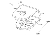
- FIG. 1 is a cross-sectional view showing an embodiment of a solenoid valve according to the present invention. It is a perspective view of the yoke shown in FIG. It is a partial cross section figure which shows the structure of the notch part of FIG. It is a figure explaining the width
- the solenoid valve 10 of the present embodiment is a normally closed solenoid valve that opens (communication state) when energized and closes (disconnected state) when not energized.
- the solenoid valve 10 is provided with a cylindrical housing 11.
- the housing 11 is configured of a cylindrical sleeve 12 and a cylindrical valve body 13 liquid-tightly fixed to one end side (lower side in FIG. 1) of the sleeve 12.
- the sleeve 12 is formed of a nonmagnetic material.
- the stator 14 is liquid-tightly fixed to the other end side (upper side in the vertical direction in FIG. 1) of the sleeve 12.
- the stator 14 is formed in a columnar shape from a magnetic material.
- the sleeve 12 is internally disposed between the stator 14 and the valve body 13 and accommodates a plunger 15 as a mover that moves along the axis Jo of the housing 11 or the sleeve 12.
- a stopper pin SP that restricts the movement of the plunger 15 is provided on the side (the lower side in the vertical direction in FIG. 1) of the stator 14 facing the plunger 15 in order to abut the adjacent plunger 15.
- the plunger 15 is formed in a columnar shape from a magnetic material, and the outer peripheral surface 15 a of the plunger 15 has an outer diameter slightly smaller than the inner diameter of the inner peripheral surface 12 a of the sleeve 12. Thereby, a clearance exists between the inner peripheral surface 12a of the sleeve 12 and the outer peripheral surface 15a of the plunger 15, and the plunger 15 is along the radial direction (left and right direction in FIG. 1) of the sleeve 12 as described later. It is possible to move.
- the sleeve 12 is assembled in a compressed state between the stator 14 and the plunger 15 to urge the spring S as a biasing member for biasing the plunger 15 along the axis Jo of the sleeve 12 (i.e., the housing 11). It accommodates. More specifically, the spring S is accommodated in an accommodation hole 15b provided on one end side (upper side in the vertical direction in FIG. 1) of the plunger 15. Thereby, the plunger 15 is biased toward the valve body 13 along the axis Jo of the sleeve 12 by the biasing force of the spring S.
- the valve body 13 is formed in a cylindrical shape extending from the magnetic material along the axis Jo.
- An annular protrusion 13a is formed on one end side (upper side in the vertical direction in FIG. 1) of the valve body 13, and is inserted into one end side (lower side in the vertical direction in FIG. 1) of the sleeve 12 It is fixed to Further, at the central portion of the valve body 13, a pair (left and right direction in FIG. 1) of outflow holes 13b for allowing the fluid to flow out is provided. Further, a seat member 16 is fluid-tightly fixed to an inflow hole 13c (lower side in the vertical direction in FIG. 1) through which the fluid of the valve body 13 flows.
- the sheet member 16 is formed in a columnar shape from a nonmagnetic material.
- the seat member 16 is formed with a valve seat 16a, a valve hole 16b and an inflow passage 16c so as to be coaxial with the axis Jo.
- the valve seat 16 a can be brought into contact (seated or released) with a later-described valve body 17 moving integrally with the plunger 15.
- the valve seat 16 a is formed in a conical shape having a conical surface in which the cross-sectional shape along the axis Jo is concave toward the valve body 17.
- valve hole 16b in the present embodiment causes the fluid flowing from the inflow passage 16c to flow out of the valve body 13 through the flow passage Z indicated by a broken line in FIG. It flows into the hole 13b.
- the inner diameter of the valve hole 16b is smaller than the inner diameter of the inflow hole 13c and the inner diameter of the inflow path 16c, as shown in FIG.
- the valve body 17 is formed to have a spherical surface projecting from the nonmagnetic material in the direction of the axis Jo.
- the proximal end 17a of the valve body 17 is fixed to the other surface side (lower side in the vertical direction in FIG. 1) of the plunger 15, and moves integrally with the plunger 15 along the direction of the axis Jo.
- the tip 17 b of the valve body 17 is formed in a spherical shape, and is seated or released from the valve seat 16 a having a conical surface.
- the solenoid valve 10 in the present embodiment is a normally closed solenoid valve in which the valve body 17 (tip portion 17 b) is seated on the valve seat 16 a of the seat member 16 when the coil 18 is not energized.
- a coil 18 is provided on the outer periphery of the sleeve 12.
- the coil 18 is configured by winding a copper wire 18 b around a bobbin 18 a.
- the coil 18 is equipped with the coil terminal 18c which supplies electric power to the copper wire 18b.
- a yoke 19 is provided on the outer periphery of the coil 18 so as to surround the coil 18 and forms a magnetic circuit together with the stator 14 and the plunger 15 when the coil 18 is energized.
- the yoke 19 of the present embodiment includes a plate-shaped first member 19 a and a plate-shaped second member 19 b orthogonal to and in parallel to the direction of the axis Jo, and the axis
- the third member 19c is connected in parallel to the direction of Jo and connects one end side which is a part of the first member 19a and the second member 19b. That is, as shown in FIGS. 1 and 2, the yoke 19 of the present embodiment is formed in a U-shape including the third member 19c.
- a stator side insertion hole 19a1 as a first insertion hole for inserting the stator 14 is formed.
- a sleeve side insertion hole 19b1 as a second insertion hole through which the sleeve 12 is inserted is formed in the second member 19b.
- the stator side insertion hole 19a1 and the sleeve side insertion hole 19b1 are coaxial along the direction of the axis Jo.
- the yoke 19 approaches the valve body 17 housed inside the sleeve 12 among the stator side insertion hole 19a1 and the sleeve side insertion hole 19b1. It has a notch 19d formed in the sleeve side insertion hole 19b1 which is the side to be moved. As shown in FIG. 2 and FIG. 3, the notches 19 d are the points P 1 and P 2 which are two points on the circumference 19 b 2 that form the sleeve side insertion hole 19 b 1.
- the yoke 19 is formed to be notched and extended toward the left in the left-right direction in a state where the yoke 19 is assembled to the sleeve 12 There is.
- the third member 19c is disposed on the right side in the left-right direction with the yoke 19 assembled to the sleeve 12, so the notch 19d has the axis Jo against the third member 19c.
- the notch 19d has a width W as a minimum distance between the two points P1 and P2 (corresponding to the length of a straight line connecting the points P1 and P2) as specifically shown in FIG. .
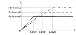
- the width W of the notch 19d is set based on the target suction force Fd for suctioning the plunger 15 with respect to the suction force F which increases with the increase of the width W, as shown in FIGS. 4 and 5.
- the notch 19 d has a length L which is a distance in a direction orthogonal to the straight line connecting the two points P 1 and P 2. As shown in FIG. 4 and FIG.
- the length L of the notch 19 d increases with the increase of the length L at the set width W, regardless of the increase of the length L. It is set to be equal to or greater than a predetermined length Ld which becomes constant at the force Fd.
- a predetermined length Ld which becomes constant at the force Fd.
- the solenoid valve 10 fluid is supplied from the inflow path 16 c of the sheet member 16.
- the plunger 15 in a state where the coil 18 is not energized, the plunger 15 is biased downward (downward in the vertical direction in FIG. 1) along the direction of the axis Jo by the biasing force of the spring S.
- the valve body 17 integrally fixed to the plunger 15 is also urged toward the lower side in the vertical direction in FIG. 1 along the direction of the axis Jo, and the tip 17 b is a valve of the seat member 16. It is seated on the seat 16a.
- the plunger 15 is moved upward along the axis Jo against the biasing force of the spring S by the magnetic circuit formed together with the stator 14 and the yoke 19 (upper and lower in FIG. Move toward the upper direction).
- the valve body 17 integrally fixed to the plunger 15 also moves upward (upward in the vertical direction in FIG. 1) along the direction of the axis Jo, and the tip end 17b is separated from the valve seat 16a.
- the tip end portion 17b of the valve body 17 is separated from the valve seat 16a, the fluid flows from the valve hole 16b to the outflow hole 13b of the valve body 13 via the flow path Z.
- a suction force F (target suction force Fd), which is an electromagnetic force for suctioning the plunger 15 together with the body 17 toward the inner circumferential surface 12 a of the sleeve 12, is generated.
- target suction force Fd an electromagnetic force for suctioning the plunger 15 together with the body 17 toward the inner circumferential surface 12 a of the sleeve 12
- the outer peripheral surface 15 a of the plunger 15 is pressed against the inner peripheral surface 12 a of the sleeve 12 to suppress self-excited vibration generated in the plunger 15 and the valve body 17.
- the yoke 19 when the coil 18 is energized, the yoke 19 includes the plunger 15 to form a magnetic circuit.
- the plunger 15 acts in a direction along the axis Jo, specifically, in the present embodiment, an electromagnetic force in the vertical direction attracted toward the stator 14 acts, and the diameter of the sleeve 12 orthogonal to the axis Jo The electromagnetic force also acts in the direction along the direction.
- the electromagnetic force in the radial direction uniformly acts over the entire circumference of the plunger 15, in other words, acts in a balanced manner. Therefore, in this case, the electromagnetic forces in the radial direction act symmetrically with respect to the axis Jo and thus cancel each other.
- the electromagnetic force acting in the direction along the radial direction is inversely proportional to the distance between the plunger 15 and the sleeve side insertion hole 19b1.
- the electromagnetic force in the radial direction in the circumferential direction of the plunger 15 is unbalanced.
- the electromagnetic force of the portion provided with the notch 19d is smaller than the electromagnetic force of the other portion not provided with the notch 19d. .
- a suction force F is generated which sucks the plunger 15 toward the inner peripheral surface 12a of the sleeve 12 due to the difference in the electromagnetic force.
- the action of the generated suction force F causes the plunger 15 to move to one side with respect to the axis Jo, specifically, in the direction opposite to the formation position of the notch 19d. It is attracted
- the suction force F generated due to the imbalance of the electromagnetic force in the direction along the radial direction is the size of the notch 19d, more specifically, the width W and the length L of the notch 19d. Depends on This will be specifically described below with reference to FIGS. 4 and 5.
- the width W of the notch 19d is fixed to the width W1, which is the minimum distance between the point P11 and the point P12, as shown by the thick solid line in FIG.
- the suction force F has a predetermined length L as shown by a solid line in FIG.
- Ld Ld
- Fmax the maximum value
- the suction force F becomes constant at the maximum value Fmax (W1) (that is, the target suction force Fd) regardless of the increase in the length L. That is, between the suction force F and the length L of the notch 19d, the suction force F increases toward the maximum value Fmax (W1) when the length L is less than the predetermined length Ld (W1).
- the suction force F is constant at the maximum value Fmax (W1).
- the width W of the notched portion 19d is set to a width W2 (minimum distance between the point P12 and the point P22) larger than the width W1 as shown by an alternate long and short dash line in FIG.
- the maximum value Fmax (W2) which is the target suction force Fd is larger than the maximum value Fmax (W1) at the width W1
- the predetermined length Ld (W2) is the predetermined at the width W1. It becomes larger than the length Ld (W1).
- the width W of the notch 19d is a width W3 (minimum distance between P13 and P23) larger than the width W2, two points are shown in FIG.
- the maximum value Fmax (W3) of the target suction force Fd is larger than the maximum value Fmax (W2) at the width W2, and the predetermined length Ld (W3) is the predetermined at the width W2. It becomes larger than the length Ld (W2).
- the width W is set according to the target suction force Fd, ie, the maximum value Fmax, and the notch 19d is formed to have a length L equal to or greater than the predetermined length Ld determined by the width W.
- the yoke 19 can apply a suction force F to the plunger 15 that matches the maximum value Fmax (the target suction force Fd).
- the ratio (Ld / W) of the predetermined length Ld to the width W is defined as a relationship established between the width W and the length L (more specifically, the predetermined length Ld) which determine the shape of the notch 19d.
- Equation 1 is established for.
- ⁇ is a straight line connecting point P1 (P11, P12, P13) and center point O of sleeve side insertion hole 19b1, and point P2 (P21, P21, A central angle formed by a straight line connecting P22 and P23) and the central point O of the sleeve side insertion hole 19b1 is shown. That is, the central angle ⁇ is a parameter related to the width W.
- Ld / W 0.12 ⁇ + 0.17 formula 1
- the central angle ⁇ is arbitrarily set based on the target suction force Fd such that the angle W is 180 degrees or less, in other words, the width W is equal to or less than the diameter of the sleeve side insertion hole 19b1.
- the central angle ⁇ is set to less than 180 degrees in order to reliably hold the sleeve 12 by the sleeve side insertion hole 19b1.
- the notch 19d is connected to the circumference 19b2 of the sleeve side insertion hole 19b1 at the points P1 and P2, sharp edges may be generated at the points P1 and P2 and deformation or breakage may occur at the time of assembly. . Therefore, in order to eliminate sharp edges, preferably, the central angle ⁇ should be set to 90 degrees or more.
- the length L may be equal to or greater than the predetermined length Ld. Therefore, the range of the ratio of the distance L to the width W (L / W) can be expressed by the following equation 2. L / W ⁇ 0.12 ⁇ + 0.17 formula 2
- the solenoid valve 10 of the above embodiment includes the cylindrical sleeve 12, the inflow hole 13c which is fluid-tightly fixed on one end side of the sleeve 12 and allows the fluid to flow, and the fluid
- Plunger 15 as a mover which is disposed to move along axis Jo of sleeve 12
- spring S as a biasing member which biases plunger 15 along axis Jo, and fixed inside valve body 13
- the seat member 16 having the valve seat 16a and the valve hole 16b communicating with the valve seat 16a, and the plunger 15 integrally moved along the axis Jo to be seated and separated from the valve seat 16a
- the sleeve 12 is coaxially inserted through the valve body 17, the coil 18 provided on the outer periphery of the sleeve 12, the stator side insertion hole 19
- a yoke 19 which has a sleeve side insertion hole 19b1 as a second insertion hole and which is provided so as to surround the coil 18 and which forms a magnetic circuit together with the stator 14 and the plunger 15 when the coil 18 is energized. It is a solenoid valve.
- the yoke 19 has two points on the circumference 19b2 forming the sleeve side insertion hole 19b1, which is the insertion hole of at least one of the stator side insertion hole 19a1 and the sleeve side insertion hole 19b1. It cuts out and extends from P1 and point P2 toward the outer side of circumference 19b2, has a minimum distance between point P1 and point P2 as width W, and is orthogonal to a straight line from a straight line connecting point P1 and point P2 And the width W of the notch 19d is opposite to the direction in which the notch 19d is formed with respect to the axis Jo when the coil 18 is energized.
- the length L is set such that the suction force F increasing with the increase of the length L at the set width W is equal to or greater than the predetermined length Ld which becomes constant at the maximum value Fmax regardless of the increase of the length L Be done.
- the width W of the notch 19d can be determined according to the target suction force Fd necessary for suctioning the plunger 15 toward the inner peripheral surface 12a of the sleeve 12, and the notch The length L of 19 d can be determined to be equal to or greater than a predetermined length Ld determined according to the determined width W. Then, by forming the notched portion 19d having the determined width W and length L in the yoke 19 together with the sleeve side insertion hole 19b1, a suction force that reliably matches the target suction force Fd when the coil 18 is energized F can be generated, and the outer peripheral surface 15 a of the plunger 15 is pressed against the inner peripheral surface 12 a of the sleeve 12.
- the solenoid valve 10 operates with the energization of the coil 18, for example, the occurrence of self-oscillation of the plunger 15 and the valve body 17 due to the fluid force of the fluid flowing in and out can be suppressed well. It is possible to significantly reduce the generation of abnormal noise when the solenoid valve 10 is activated.
- the target suction force Fd (maximum value Fmax) becomes larger, and when the length L is equal to or more than the predetermined length Ld, the suction force F which is equal to the maximum value Fmax can be generated.
- the processing cost of the yoke 19 (notched portion 19d) can be reduced, and the yield of the yoke 19 can be improved, and hence the manufacturing cost of the solenoid valve 10 can be reduced.
- the notched portion 19d uses the central angle ⁇ formed by a straight line connecting the center point O of the sleeve side insertion hole 19b1 and each of the point P1 and the point P2 in relation to the width W.
- the width W and the length L are set such that the ratio (L / W) of the length L satisfies L / W ⁇ 0.12 ⁇ + 0.17 shown as the equation 2.
- the yoke 19 reliably makes the plunger 15 the inner circumferential surface 12 a of the sleeve 12. It is possible to generate a suction force F (target suction force Fd) to be directed and suctioned. Therefore, the generation of the self-excited vibration of the plunger 15 and the valve body 17 can be favorably suppressed, and the generation of the abnormal noise at the time of operation of the solenoid valve 10 can be significantly reduced.
- the notch 19d is a side of the stator side insertion hole 19a1 and the sleeve side insertion hole 19b1 that comes close to the valve body 17 housed inside the sleeve 12 in a state where the sleeve 12 is inserted. It is provided in the sleeve side penetration hole 19b1 which is.
- the notch 19d can be provided in the sleeve side insertion hole 19b1
- the suction force on the valve body 17 side of the plunger 15, ie, the side where the amplitude tends to be large F (target suction force Fd) can be applied.
- the outer peripheral surface 15a on the valve body 17 side of the plunger 15 is pressed against the inner peripheral surface 12a of the sleeve 12, so that the occurrence of self-excited vibration can be effectively suppressed. Therefore, it is possible to effectively reduce the generation of abnormal noise when the solenoid valve 10 is activated.
- the yoke 19 includes a plate-shaped first member 19a having a stator-side insertion hole 19a1, a plate-shaped second member 19b having a sleeve-side insertion hole 19b1, and a parallel to the axis Jo and
- the third member 19c connects a part of the one member 19a and a part of the second member 19b, and the notch 19d is on the opposite side of the axis Jo to the third member 19c.
- the notch 19d can be provided at a position separated from the third member 19c.
- the third member 19c and the third member 19c are formed when forming the notch 19d or when adjusting the width W and the length L of the notch 19d according to the suction force F (target suction force Fd). Work can be done without interference. Therefore, the yoke 19 and thus the solenoid valve 10 can be easily manufactured.
- a rectangular notch 19 d is formed in the sleeve side insertion hole 19 b 1 of the second member 19 b of the yoke 19.
- the notch 19 d is formed in an arc shape.
- the notches 19 d are formed so that the sides extending in the direction of the length L are parallel to each other. Instead of this, it is also possible to form the notch 19 d so that the sides extending in the direction of the length L have an angle with each other.
- the electromagnetic valve 10 in the said embodiment was used as the normally closed electromagnetic valve, it is also possible to apply to a normally open electromagnetic valve.
- the spring S is, for example, between the other end (lower side in the vertical direction in FIG. 1) of the plunger 15 and a convex portion (partition or the like) provided on the inner peripheral surface of the valve body 13 In the compressed state.
- the solenoid valve 10 is a normally-open type solenoid valve
- the outer peripheral surface of the plunger 15 has a notch 19 d and the suction force F that matches the target suction force Fd is applied to the plunger 15. Since the 15a is pressed against the inner circumferential surface 12a of the sleeve 12, the vibration generated due to the fluid force of the fluid immediately before the tip 17b of the valve body 17 is seated on the valve seat 16a when the coil 18 is energized Vibration) can be effectively suppressed. Therefore, even if the solenoid valve 10 is a normally open solenoid valve, the same effect as that of the above embodiment can be obtained. In the case of a normally-opened solenoid valve, the valve body 17 can be aligned with the valve seat 16a by the distal end 17b of the valve body 17 being seated on the valve seat 16a.
- the solenoid valve 10 demonstrated in the said embodiment is applicable to the solenoid valve which comprises the brake control system of a vehicle, for example.
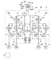
- a brake control system to which the solenoid valve 10 can be applied will be briefly described with reference to FIG.
- the brake control system includes, as the cylinder mechanism 23, a master cylinder (M / C) 230, master pistons 231 and 232, and a master reservoir 233.
- the wheel cylinders 24, 25, 26, 27 are respectively disposed on the left rear wheel RL, the right rear wheel RR, the left front wheel FL, and the right front wheel FR to apply a braking force.
- the depression force is boosted by the booster 22, and the master pistons 231 and 232 in the master cylinder 230 are pressed.
- the master cylinder pressure of the same pressure is generated in the first master chamber 230a and the second master chamber 230b.
- the master cylinder pressure is transmitted to wheel cylinders 24-27 via actuator 5.
- the actuator 5 is a device that controls the wheel pressure of the wheel cylinders 24 to 27 in accordance with an instruction from the brake control device 6.
- the actuator 5 includes a hydraulic circuit 50 as shown in FIG.
- the hydraulic circuit 50 has a first piping system 50a and a second piping system 50b.
- the first piping system 50a is a system that controls the wheel pressure applied to the left rear wheel RL and the right rear wheel RR.
- the second piping system 50b is a system that controls the wheel pressure applied to the left front wheel FL and the right front wheel FR.
- the first piping system 50a and the second piping system 50b are the same, hereinafter, the first piping system 50a will be described, and the description of the second piping system 50b will be omitted.
- the first piping system 50a includes the main pipe A, the differential pressure control valve 51 and the check valve 51a, the pressure increasing valves 52 and 53, the pressure reducing line B, the pressure reducing valves 54 and 55, and the pressure control reservoir 56.
- a return line C and an auxiliary line D are provided, which can be controlled by the brake control device 6 to perform so-called automatic brake control and anti-slip control.
- the solenoid valve 10 (including the normally open solenoid valve) described in the above embodiment can be applied to each of the differential pressure control valve 51, the pressure increasing valves 52, 53, and the pressure reducing valves 54, 55.
- the reflux pipeline C has a discharge side passage C1 connecting the discharge passage of the pump 57 driven by the motor 8 and the main pipeline A.
- the discharge side passage C1 is provided with a damper 7 for absorbing the discharge pulsation of the pump 57, and a check valve 1 between the damper 7 and the main conduit A.
- the solenoid valve 10 When the above-described solenoid valve 10 is applied to the differential pressure control valve 51, the pressure increasing valves 52, 53 and the pressure reducing valves 54, 55 of the brake control system of a vehicle, for example, the solenoid valve according to automatic brake control or anti-slip control. It is conceivable that the frequency of opening and closing of 10 increases. When the open / close operation frequency of the solenoid valve 10 increases, the plunger 15 and the valve body 17 easily generate self-excited vibration, which increases the possibility that the solenoid valve 10 generates abnormal noise.
- the solenoid valve 10 is provided with the yoke 19 having the notch 19d, and as described above, the suction force F can be generated that matches the target suction force Fd. Therefore, a brake control system of a vehicle provided with an electromagnetic valve provided in an oil passage connecting between master cylinder 230 and wheel cylinders 24-27 and communicating or blocking master cylinder 230 with wheel cylinders 24-27 is provided. Even when the solenoid valve 10 is applied to the pressure control device, the self-excited vibration of the plunger 15 and the valve body 17 can be suppressed to effectively suppress the generation of abnormal noise when the solenoid valve 10 is operated. it can.
- the sleeve side insertion hole 19b1 (that is, the second member of the yoke 19) of the stator side insertion hole 19a1 and the sleeve side insertion hole 19b1 which is the side closer to the valve body 17
- the notch 19d is provided in 19b).
- the notch 19 d is provided in the stator side insertion hole 19 a 1
- the suction force F can be generated on the side of the stator 14 of the plunger 15 so as to match the target suction force Fd.
- the outer circumferential surface 15 a is pressed against the inner circumferential surface 12 a of the sleeve 12.
- the target suction force Fd matches the stator 14 side of the plunger 15 and the valve body 17 side.
- the suction force F can be generated, and the outer peripheral surface 15 a of the plunger 15 is pressed against the inner peripheral surface 12 a of the sleeve 12.
- the plunger 15 is pressed against the inner peripheral surface 12a of the sleeve 12 without being inclined with respect to the axis Jo, so that the occurrence of vibration (self-excited vibration) can be suppressed.
Landscapes
- Engineering & Computer Science (AREA)
- General Engineering & Computer Science (AREA)
- Physics & Mathematics (AREA)
- Electromagnetism (AREA)
- Mechanical Engineering (AREA)
- Power Engineering (AREA)
- Magnetically Actuated Valves (AREA)
- Electromagnets (AREA)
Abstract
ヨーク(19)は、スリーブ側挿通孔(19b1)を形成する円周(19b2)の上の二点である点P1及び点P2から円周(19b2)の外方に向けて切り欠かれ、点P1及び点P2の間の最小距離を幅Wとして有するとともに点P1及び点P2を結ぶ直線から直線に直交する方向の距離を長さLとして有する切欠き部(19d)を備える。切欠き部(19d)の幅Wは、幅Wの増加に伴って増加する吸引力についてプランジャ(15)を吸引する目標吸引力に基づいて設定され、切欠き部(19d)の長さLは、設定された幅Wにおいて長さLの増加に伴って増加する吸引力が長さLの増加に拘わらず目標吸引力で一定となる所定長さLd以上となるように設定される。
Description
本発明は、電磁弁に関する。
従来から、例えば、下記特許文献1に開示された制御弁が知られている。この従来の制御弁は、PWM方式による通電制御がなされて弁体を閉弁方向に駆動するための磁気吸引力を発生させるソレノイドを備えている。ソレノイドは、ボビンと、ボビンに巻回されたコイルと、ボビンと同軸状にボディに固定されたコアと、ボビンの内方にてコアと軸線の方向に沿って対向配置されて伝達ロッドと一体変位するプランジャと、コア及びプランジャとともにコイルを取り囲むように設けられてコイルへの通電時に磁気回路を形成するヨークと、ボビンの軸線に対して非対称な構造部分からなり、プランジャに作用する径方向の磁気吸引力のバランスを片側に偏らせる非対称構造としてカラーの内周面に凹状の切欠きを有するようになっている。そして、従来の制御弁においては、磁気吸引力のバランスを片側に偏らせることにより、プランジャの微小振動によるノイズを抑えるようになっている。
上記従来の制御弁においては、カラーに凹状の切欠きを設けることにより、プランジャ(可動子)の周方向に沿った方向おいて磁気吸引力の強弱を生じさせて、可動子を径方向に吸引する吸引力を発生させる。しかしながら、上記従来の制御弁において、カラーに形成される切欠きは、凹状の幅及び長さについて何ら規定されておらず、切欠きの幅及び長さが小さい場合には、可動子を軸線に対して片側に吸引する吸引力が不十分になる。その結果、吸引力によって可動子を径方向に吸引することができず、可動子が作動する際の摺動抵抗が不足して微小振動によるノイズを抑えることが困難になる。
本発明は、上述した問題を解消するためになされたものである。即ち、本発明の目的は、可動子を軸線に対して片側に吸引する吸引力を確実に発生させて、作動時における異音の発生を抑制する電磁弁を提供することにある。
上記の課題を解決するため、請求項1に係る電磁弁の発明は、筒状のスリーブと、スリーブの一端側にて液密に固定されて流体を流入させる流入孔及び流体を流出させる流出孔を有する筒状のバルブボディと、スリーブの他端側にて液密に固定された固定子と、スリーブの内部にて固定子とバルブボディとの間に配置されてスリーブの軸線に沿って移動する可動子と、可動子を軸線に沿って付勢する付勢部材と、バルブボディの内部にて固定されて弁座及び弁座に連通する弁孔を有するシート部材と、可動子と一体に軸線に沿って移動して弁座に対して着座及び離座する弁体と、スリーブの外周に設けられたコイルと、固定子を挿通する第一挿通孔と第一挿通孔に同軸でスリーブを挿通する第二挿通孔とを有し、コイルを取り囲むように設けられてコイルへの通電時に固定子及び可動子とともに磁気回路を形成するヨークと、を備えた電磁弁であって、ヨークは、第一挿通孔及び第二挿通孔のうちの少なくとも一方の挿通孔を形成する円周の上の二点から円周の外方に向けて切り欠かれて延在し、二点の間の最小距離を幅として有するとともに二点を結ぶ直線から直線に直交する方向の距離を長さとして有する切欠き部を備え、切欠き部の幅は、コイルへの通電時において、軸線に対して切欠き部の形成位置とは反対方向にて弁体とともに可動子をスリーブの内周面に向けて吸引する吸引力幅の増加に伴って増加する吸引力の目標吸引力に基づいて設定され、切欠き部の長さは、設定された幅において長さの増加に伴って増加する吸引力が長さの増加に拘わらず目標吸引力で一定となる所定長さ以上となるように設定される。
これによれば、可動子を切欠き部の形成位置とは反対方向にてスリーブの内周面に向けて吸引する、即ち、可動子を軸線に対して片側に吸引する際に必要な目標吸引力に応じて、切欠き部の幅を決定することができるとともに、切欠き部の長さを、決定された幅に応じて決定される所定長さ以上に決定することができる。そして、決定された幅及び長さを有する切欠き部をヨークに形成することにより、コイルへの通電時において確実に目標吸引力に一致する吸引力を発生させることができて、可動子を軸線に対して片側に吸引することができる。従って、コイルへの通電に伴って電磁弁が作動する際において、可動子がスリーブの内周面に押し付けられることにより、可動子及び弁体の振動(自励振動)の発生を良好に抑制することができ、電磁弁の作動時における異音の発生を大幅に低減することができる。
以下、本発明の実施形態について図面を参照しながら説明する。尚、以下の実施形態及び各変形例の相互において、互いに同一又は均等である部分には、図中、同一の符号を付してある。又、説明に用いる各図は概念であり、各部の形状は必ずしも厳密なものではない場合がある。
本実施形態の電磁弁10は、図1に示すように、通電時に開弁し(連通状態)、非通電時に閉弁する(遮断状態)、常閉型の電磁弁である。電磁弁10は、筒状のハウジング11を備えている。ハウジング11は、筒状のスリーブ12と、このスリーブ12の一端側(図1にて上下方向下側)に液密に固定された円筒状のバルブボディ13と、から構成されている。
スリーブ12は、非磁性体材料から形成されている。スリーブ12は、他端側(図1にて上下方向上側)に固定子14が液密に固定されている。固定子14は、磁性体材料から柱状に形成されている。又、スリーブ12は、内部にて、固定子14とバルブボディ13との間に配置されて、ハウジング11即ちスリーブ12の軸線Joに沿って移動する可動子としてのプランジャ15を収容している。尚、固定子14のプランジャ15との対向側(図1にて上下方向下側)には、近接するプランジャ15と当接して、プランジャ15の移動を規制するストッパピンSPが設けられている。
プランジャ15は、磁性体材料から柱状に形成されており、プランジャ15の外周面15aはスリーブ12の内周面12aの内径に比べて僅かに小さい外径を有している。これにより、スリーブ12の内周面12aとプランジャ15の外周面15aとの間にはクリアランスが存在し、後述するように、プランジャ15はスリーブ12の径方向(図1にて左右方向)に沿って移動可能となっている。
又、スリーブ12は、固定子14とプランジャ15との間に圧縮状態で組み付けられて、プランジャ15をスリーブ12(即ちハウジング11)の軸線Joに沿って付勢する付勢部材としてのスプリングSを収容している。より具体的に、スプリングSは、プランジャ15の一端側(図1にて上下方向上側)に設けられた収容穴15bの内部に収容される。これにより、プランジャ15は、スプリングSの付勢力により、スリーブ12の軸線Joに沿ってバルブボディ13に向けて付勢される。
バルブボディ13は、図1に示すように、磁性体材料から軸線Joに沿って延出する筒状に形成されている。バルブボディ13の一端側(図1にて上下方向上側)には、環状の突部13aが形成されており、スリーブ12の一端側(図1にて上下方向下側)に挿入されて液密に固定されている。又、バルブボディ13の中央部分には、流体を流出させる一対(図1にて左右方向)の流出孔13bが設けられている。更に、バルブボディ13の流体を流入させる流入孔13c(図1にて上下方向下側)には、シート部材16が液密に固定されている。
シート部材16は、非磁性体材料から柱状に形成されている。シート部材16は、図1に示すように、軸線Joと同軸となるように、弁座16a、弁孔16b及び流入路16cが形成されている。弁座16aは、プランジャ15と一体に移動する後述の弁体17と当接(着座又は離座)可能とされている。弁座16aは、軸線Joに沿った断面形状が弁体17に向けて凹状となる円錐面を有する円錐状に形成されている。これにより、弁体17が弁座16aに着座した場合、弁体17と弁座16aとの軸線が一致するように、調心されるようになっている。
本実施形態における弁孔16bは、弁座16aに対して弁体17が離座した場合、流入路16cから流入した流体を図1にて破線により示す流路Zを通ってバルブボディ13の流出孔13bに流すものである。弁孔16bの内径は、図1に示すように、流入孔13cの内径及び流入路16cの内径に比して小さくなっている。
弁体17は、図1に示すように、非磁性体材料から軸線Joの方向に突出する球面を有するように形成されている。弁体17は、基端部17aがプランジャ15の他面側(図1にて上下方向下側)に固定され、プランジャ15と一体に軸線Joの方向に沿って移動するようになっている。弁体17の先端部17bは、球状に形成されており、円錐面を有する弁座16aに対して着座又は離座する。本実施形態における電磁弁10は、コイル18に通電されない場合に弁体17(先端部17b)がシート部材16の弁座16aに着座する常閉型の電磁弁である。
又、スリーブ12の外周には、コイル18が設けられている。コイル18は、ボビン18aに銅線18bを巻き付けて構成されている。そして、コイル18は、銅線18bに電力を供給するコイル端子18cを備えている。コイル18の外周には、コイル18を取り囲むように設けられて、コイル18への通電時に固定子14及びプランジャ15とともに磁気回路を形成するヨーク19が設けられている。
本実施形態のヨーク19は、図1及び図2に示すように、軸線Joの方向に対して直交して互いに平行となる板状の第一部材19a及び板状の第二部材19bと、軸線Joの方向に平行で且つ第一部材19a及び第二部材19bの一部である一端側を連結する第三部材19cから構成されている。即ち、本実施形態のヨーク19は、図1及び図2に示すように、第三部材19cを備えたコの字状に形成されている。第一部材19aには、固定子14を挿通する第一挿通孔としての固定子側挿通孔19a1が形成されている。又、第二部材19bには、スリーブ12を挿通する第二挿通孔としてのスリーブ側挿通孔19b1が形成されている。固定子側挿通孔19a1及びスリーブ側挿通孔19b1は、軸線Joの方向に沿って同軸となっている。
又、本実施形態において、ヨーク19は、図1~図3に示すように、固定子側挿通孔19a1及びスリーブ側挿通孔19b1のうちの、スリーブ12の内部に収容された弁体17に近接する側であるスリーブ側挿通孔19b1に形成された切欠き部19dを備えている。切欠き部19dは、図2及び図3に示すように、スリーブ側挿通孔19b1を形成する円周19b2の上の二点である点P1及び点P2から円周19b2の外方(スリーブ側挿通孔19b1の中心点Oから離間する方向であって本実施形態においてヨーク19がスリーブ12に組み付けられた状態にて左右方向における左方向)に向けて切り欠かれて延在するように形成されている。これにより、本実施形態においては、図1に示すように、ヨーク19がスリーブ12に組み付けられた状態にて第三部材19cが左右方向における右側に配置されるため、切欠き部19dは軸線Joに対して第三部材19cとは反対側に設けられている。
切欠き部19dは、図3に具体的に示すように、二点である点P1及び点P2の間の最小距離(点P1及び点P2を結ぶ直線の長さに相当)を幅Wとしている。切欠き部19dの幅Wは、図4及び図5に示すように、幅Wの増加に伴って増加する吸引力Fについてプランジャ15を吸引する目標吸引力Fdに基づいて設定される。又、切欠き部19dは、図3に具体的に示すように、二点である点P1及び点P2を結ぶ直線からこの直線に直交する方向の距離を長さLとしている。切欠き部19dの長さLは、図4及び図5に示すように、設定された幅Wにおいて長さLの増加に伴って増加する吸引力Fが長さLの増加に拘わらず目標吸引力Fdで一定となる所定長さLd以上となるように設定される。以下、切欠き部19dの幅W及び長さLの設定について詳述する。
電磁弁10においては、シート部材16の流入路16cから流体が供給される。電磁弁10においては、コイル18に通電されない状態では、プランジャ15がスプリングSの付勢力によって軸線Joの方向に沿って下方(図1にて上下方向下側)に向けて付勢されている。これにより、プランジャ15に一体に固定された弁体17も軸線Joの方向に沿って(図1にて上下方向下側)に向けて付勢されており、先端部17bがシート部材16の弁座16aに着座している。
一方、コイル18の通電時においては、プランジャ15は固定子14及びヨーク19とともに形成される磁気回路により、スプリングSの付勢力に抗して軸線Joの方向に沿って上方(図1にて上下方向上側)に向けて移動する。これにより、プランジャ15に一体に固定された弁体17も軸線Joの方向に沿って上方(図1にて上下方向上側)に向けて移動し、先端部17bが弁座16aから離座する。弁体17の先端部17bが弁座16aから離座すると、流体が弁孔16bから流路Zを介してバルブボディ13の流出孔13bに向けて流動する。
ここで、弁体17が弁座16aから離座した直後や、流路Zを流動する流体の流量変化が大きい場合、弁体17に流体の流体力が作用し、弁体17がスリーブ12の径方向(図1にて左右方向)に振動する、所謂、自励振動が発生する可能性がある。この自励振動に対して、電磁弁10においては、コイル18への通電時において、ヨーク19に幅W及び長さLを適切に設定した切欠き部19dの形成位置とは反対方向にて弁体17とともにプランジャ15をスリーブ12の内周面12aに向けて吸引する電磁力である吸引力F(目標吸引力Fd)を発生させる。これにより、プランジャ15の外周面15aがスリーブ12の内周面12aに押し付けられ、プランジャ15及び弁体17に発生する自励振動を抑制する。
上述したように、コイル18に通電がなされると、ヨーク19はプランジャ15を含んで磁気回路を形成する。この場合、プランジャ15は、軸線Joに沿った方向、具体的に本実施形態においては固定子14に向けて吸引される上下方向の電磁力が作用するとともに、軸線Joに直交するスリーブ12の径方向に沿った方向にも電磁力が作用する。ヨーク19に切欠き部19dが設けられていない場合、径方向に沿った方向の電磁力はプランジャ15の全周に渡り均等に、換言すれば、バランスして作用する。従って、この場合には、径方向に沿った方向の電磁力は軸線Joに対して対称に作用するため、互いに相殺される。このため、ヨーク19に切欠き部19dが設けられていない場合には、プランジャ15及び弁体17は、スリーブ12の内周面12aに向けて吸引する吸引力Fが発生しないために移動することなく、コイル18への通電時において軸線Joに沿った方向にのみ移動する。
一方、ヨーク19に切欠き部19dを設けた場合、径方向に沿った方向に作用する電磁力は、プランジャ15とスリーブ側挿通孔19b1との間の距離に反比例するため、プランジャ15の周方向に沿って強弱が生じる。即ち、ヨーク19に切欠き部19dを設けた場合には、プランジャ15の周方向において、径方向に沿った方向の電磁力がアンバランスになる。具体的に、ヨーク19においては、プランジャ15の周方向にて、切欠き部19dが設けられた部分の電磁力が切欠き部19dが設けられていない他の部分の電磁力に比べて小さくなる。従って、この場合には、電磁力の差に起因してプランジャ15をスリーブ12の内周面12aに向けて吸引する吸引力Fが発生する。このため、コイル18への通電時においては、発生した吸引力Fの作用により、プランジャ15は軸線Joに対して片側、具体的には、切欠き部19dの形成位置とは反対方向に、弁体17とともにスリーブ12の内周面12aに向けて吸引される。
ところで、径方向に沿った方向の電磁力のアンバランスに起因して発生する吸引力Fは、切欠き部19dの大きさ、より具体的には、切欠き部19dの幅W及び長さLに依存する。このことを、以下図4及び図5を用いて具体的に説明する。
理解を容易とするため、図4にて太い実線により示すように、切欠き部19dの幅Wを点P11及び点P12の間の最小距離である幅W1に固定した場合を想定する。この場合において、図4にて太い長破線で示すように、切欠き部19dの長さLを増加させると、吸引力Fは、図5にて実線により示すように、長さLが所定長さLd(W1)未満まで増加するときには一様に目標吸引力Fdである最大値Fmax(W1)に向けて増大する。一方、長さLが所定長さLd(W1)以上になると、吸引力Fは、長さLの増加に拘わらず最大値Fmax(W1)(即ち、目標吸引力Fd)で一定になる。即ち、吸引力Fと切欠き部19dの長さLとの間には、長さLが所定長さLd(W1)未満において吸引力Fは最大値Fmax(W1)に向けて増大し、長さLが所定長さLd(W1)以上において吸引力Fは最大値Fmax(W1)で一定になる関係が成立する。
又、図4にて一点鎖線により示すように、切欠き部19dの幅Wを幅W1よりも大きな幅W2(点P12と点P22との間の最小距離)とした場合、図5にて一点鎖線により示すように、目標吸引力Fdである最大値Fmax(W2)は幅W1のときの最大値Fmax(W1)よりも大きくなるとともに、所定長さLd(W2)は幅W1のときの所定長さLd(W1)よりも大きくなる。更に、図4にて二点鎖線により示すように、切欠き部19dの幅Wを幅W2よりも大きな幅W3(P13とP23との間の最小距離)とした場合、図5にて二点鎖線により示すように、目標吸引力Fdである最大値Fmax(W3)は幅W2のときの最大値Fmax(W2)よりも大きくなるとともに、所定長さLd(W3)は幅W2のときの所定長さLd(W2)よりも大きくなる。
従って、目標吸引力Fd即ち最大値Fmaxに応じて幅Wを設定し、幅Wによって決定される所定長さLd以上の長さLを有するように切欠き部19dを形成する。これにより、ヨーク19は、最大値Fmax(目標吸引力Fd)と一致する吸引力Fをプランジャ15に作用させることができる。
ところで、切欠き部19dの形状を決定する幅Wと長さL(より詳しくは、所定長さLd)との間に成立する関係として、幅Wに対する所定長さLdの比(Ld/W)については、下記式1が成立する。尚、下記式1において、θは、図3及び図4に示すように、点P1(P11,P12,P13)とスリーブ側挿通孔19b1の中心点Oとを結ぶ直線と、点P2(P21,P22,P23)とスリーブ側挿通孔19b1の中心点Oとを結ぶ直線と、によって形成される中心角を表す。即ち、中心角θは、幅Wに関連するパラメータである。
Ld/W=0.12θ+0.17 …式1
Ld/W=0.12θ+0.17 …式1
但し、中心角θは、180度以下の角度、換言すれば、幅Wがスリーブ側挿通孔19b1の直径以下となるように、目標吸引力Fdに基づいて任意に設定される。尚、スリーブ側挿通孔19b1によってスリーブ12を確実に保持するために、好ましくは、中心角θは180度未満に設定されると良い。又、切欠き部19dは点P1及びP2にてスリーブ側挿通孔19b1の円周19b2と接続されるため、点P1及び点P2に鋭利なエッジが生じ、組み付け時に変形や欠損が生じる場合がある。従って、鋭利なエッジを解消するために、好ましくは、中心角θは90度以上に設定されると良い。
上述したように、最大値Fmaxに一致する吸引力Fを発生させる場合、長さLは所定長さLd以上であれば良い。従って、幅Wに対する距離Lの比(L/W)の範囲については、下記式2によって表すことができる。
L/W≧0.12θ+0.17 …式2
L/W≧0.12θ+0.17 …式2
前記式2が成立する場合、図6にて梨地により示す領域内に比(L/W)が存在する。従って、図6に示す領域内に比(L/W)が存在するように、幅W及び長さLを設定して切欠き部19dを形成することにより、コイル18への通電時において、ヨーク19は最大値Fmaxに一致する吸引力Fをプランジャ15に作用させる。
以上の説明からも理解できるように、上記実施形態の電磁弁10は、筒状のスリーブ12と、スリーブ12の一端側にて液密に固定されて流体を流入させる流入孔13c及び流体を流出させる流出孔13bを有する筒状のバルブボディ13と、スリーブ12の他端側にて液密に固定された固定子14と、スリーブ12の内部にて固定子14とバルブボディ13との間に配置されてスリーブ12の軸線Joに沿って移動する可動子としてのプランジャ15と、プランジャ15を軸線Joに沿って付勢する付勢部材としてのスプリングSと、バルブボディ13の内部にて固定されて弁座16a及び弁座16aに連通する弁孔16bを有するシート部材16と、プランジャ15と一体に軸線Joに沿って移動して弁座16aに対して着座及び離座する弁体17と、スリーブ12の外周に設けられたコイル18と、固定子14を挿通する第一挿通孔としての固定子側挿通孔19a1と固定子側挿通孔19a1に同軸でスリーブ12を挿通する第二挿通孔としてのスリーブ側挿通孔19b1とを有し、コイル18を取り囲むように設けられてコイル18への通電時に固定子14及びプランジャ15とともに磁気回路を形成するヨーク19と、を備えた電磁弁である。
電磁弁10において、ヨーク19は、固定子側挿通孔19a1及びスリーブ側挿通孔19b1のうちの少なくとも一方の挿通孔であるスリーブ側挿通孔19b1を形成する円周19b2の上の二点である点P1及び点P2から円周19b2の外方に向けて切り欠かれて延在し、点P1及び点P2の間の最小距離を幅Wとして有するとともに点P1及び点P2を結ぶ直線から直線に直交する方向の距離を長さLとして有する切欠き部19dを備え、切欠き部19dの幅Wは、コイル18への通電時において、軸線Joに対して切欠き部19dの形成位置とは反対方向にて弁体17とともにプランジャ15をスリーブ12の内周面12aに向けて吸引する吸引力Fの目標吸引力Fdとしての最大値Fmaxに基づいて設定され、切欠き部19dの長さLは、設定された幅Wにおいて長さLの増加に伴って増加する吸引力Fが長さLの増加に拘わらず最大値Fmaxで一定となる所定長さLd以上となるように設定される。
これによれば、プランジャ15をスリーブ12の内周面12aに向けて吸引する際に必要な目標吸引力Fdに応じて、切欠き部19dの幅Wを決定することができるとともに、切欠き部19dの長さLを決定された幅Wに応じて決定される所定長さLd以上に決定することができる。そして、決定された幅W及び長さLを有する切欠き部19dをスリーブ側挿通孔19b1とともにヨーク19に形成することにより、コイル18への通電時において確実に目標吸引力Fdに一致する吸引力Fを発生させることができて、プランジャ15の外周面15aがスリーブ12の内周面12aに押し付けられる。従って、コイル18への通電に伴って電磁弁10が作動する際に、例えば、流出入する流体の流体力に起因するプランジャ15及び弁体17の自励振動の発生を良好に抑制することができ、電磁弁10の作動時における異音の発生を大幅に低減することができる。
又、幅Wが大きくなるほど目標吸引力Fd(最大値Fmax)が大きくなり、長さLが所定長さLd以上であれば最大値Fmaxに一致する吸引力Fを発生させることができる。これにより、ヨーク19に切欠き部19dを形成する場合、決定された幅W及び長さLを高い加工精度及び寸法精度で切り欠く必要がなく、加工精度及び寸法精度を適宜低下させることが可能となる。従って、ヨーク19(切欠き部19d)の加工コストを低減することができるとともにヨーク19の歩留まりを改善することができ、ひいては、電磁弁10の製造コストを低減することができる。
この場合、切欠き部19dは、幅Wに関連してスリーブ側挿通孔19b1の中心点Oと点P1及び点P2のそれぞれとを結ぶ直線によって形成される中心角θを用いて、幅Wに対する長さLの比(L/W)が前記式2として示されるL/W≧0.12θ+0.17を満たすように、幅W及び長さLが設定される。
これによれば、前記式2によって表される関係を満たすように切欠き部19dの幅W及び長さLを設定することにより、ヨーク19は確実にプランジャ15をスリーブ12の内周面12aに向けて吸引する吸引力F(目標吸引力Fd)を発生させることができる。従って、プランジャ15及び弁体17の自励振動の発生を良好に抑制することができ、電磁弁10の作動時における異音の発生を大幅に低減することができる。
又、これらの場合、切欠き部19dは、固定子側挿通孔19a1及びスリーブ側挿通孔19b1のうち、スリーブ12を挿通した状態で、スリーブ12の内部に収容された弁体17に近接する側であるスリーブ側挿通孔19b1に設けられる。
電磁弁10においては、流体が流入出する場合、プランジャ15及び弁体17は、固定子14の側、即ち、ストッパピンSPとプランジャ15とが当接する位置を中心に径方向に振動(自励振動)が生じやすい。このため、プランジャ15においては弁体17の側の振幅が大きくなりやすく、その結果、電磁弁10の作動時に異音を発生させる。これに対し、本実施形態のヨーク19においては、スリーブ側挿通孔19b1に切欠き部19dを設けることができるため、プランジャ15の弁体17の側、即ち、振幅が大きくなりやすい側に吸引力F(目標吸引力Fd)を作用させることができる。その結果、プランジャ15の弁体17の側の外周面15aがスリーブ12の内周面12aに押し付けられるため、自励振動の発生を効果的に抑制することができる。従って、電磁弁10の作動時における異音の発生を効果的に低減することができる。
更に、これらの場合、ヨーク19は、固定子側挿通孔19a1を有する板状の第一部材19aと、スリーブ側挿通孔19b1を有する板状の第二部材19bと、軸線Joに平行で且つ第一部材19aの一部と第二部材19bの一部とを連結する第三部材19cと、から構成されており、切欠き部19dは、軸線Joに対して第三部材19cとは反対側に設けられる。
これによれば、ヨーク19において、切欠き部19dを第三部材19cから離間した位置に設けることができる。これにより、切欠き部19dを形成する場合や、或いは、吸引力F(目標吸引力Fd)に応じて切欠き部19dの幅W及び長さLを調整する場合等において、第三部材19cと干渉を生じることなく作業を行うことができる。従って、容易にヨーク19ひいては電磁弁10を製造することができる。
(変形例)
上記実施形態においては、ヨーク19の第二部材19bのスリーブ側挿通孔19b1に矩形状の切欠き部19dを形成するように実施した。これに代えて、図7に示すように、切欠き部19dの形状を、円弧状に形成することも可能である。又、上記実施形態においては、長さLの方向に延設された辺が互いに平行になるように、切欠き部19dを形成するようにした。これに代えて、長さLの方向に延設された辺が互いに角度を有するように、切欠き部19dを形成することも可能である。
上記実施形態においては、ヨーク19の第二部材19bのスリーブ側挿通孔19b1に矩形状の切欠き部19dを形成するように実施した。これに代えて、図7に示すように、切欠き部19dの形状を、円弧状に形成することも可能である。又、上記実施形態においては、長さLの方向に延設された辺が互いに平行になるように、切欠き部19dを形成するようにした。これに代えて、長さLの方向に延設された辺が互いに角度を有するように、切欠き部19dを形成することも可能である。
又、上記実施形態における電磁弁10は、常閉型の電磁弁としたが、常開型の電磁弁に適用することも可能である。尚、この場合には、スプリングSが、例えば、プランジャ15の他端部(図1にて上下方向下側)とバルブボディ13の内周面に設けられた凸部(隔壁等)との間にて、圧縮状態で組み付けられる。
電磁弁10が常開型の電磁弁であっても、ヨーク19が切欠き部19dを有して目標吸引力Fdに一致する吸引力Fをプランジャ15に作用させることにより、プランジャ15の外周面15aがスリーブ12の内周面12aに押し付けられるため、コイル18への通電時に弁体17の先端部17bが弁座16aに着座する直前等に流体の流体力に起因して発生する振動(自励振動)を効果的に抑制することができる。従って、電磁弁10が常開型の電磁弁であっても、上記実施形態と同様の効果が得られる。尚、常開型の電磁弁の場合、弁体17の先端部17bが弁座16aに着座することにより、弁体17を弁座16aに対して調心することができる。
ところで、上記実施形態において説明した電磁弁10は、例えば、車両のブレーキ制御システムを構成する電磁弁に適用することができる。以下、電磁弁10を適用することができるブレーキ制御システムを図8を用いて簡単に説明する。
ブレーキ制御システムにおいて、電磁弁10は、アクチュエータ5に組み込まれる。ブレーキ制御システムは、シリンダ機構23として、マスタシリンダ(M/C)230と、マスタピストン231,232と、マスタリザーバ233と、を備えている。ホイールシリンダ24,25,26,27は、それぞれ、左後輪RL、右後輪RR、左前輪FL、右前輪FRに配置されて制動力を付与する。
ブレーキ制御システムにおいては、運転者がブレーキ操作部材21を踏み込むと、倍力装置22により踏力が倍力され、マスタシリンダ230内のマスタピストン231,232が押圧される。これにより、第一マスタ室230a及び第二マスタ室230bに同圧のマスタシリンダ圧が発生する。マスタシリンダ圧は、アクチュエータ5を介してホイールシリンダ24~27に伝達される。
アクチュエータ5は、ブレーキ制御装置6の指示に応じて、ホイールシリンダ24~27のホイール圧を制御する装置である。具体的に、アクチュエータ5は、図8に示すように、油圧回路50を備えている。油圧回路50は、第一配管系統50a及び第二配管系統50bを有している。第一配管系統50aは、左後輪RL及び右後輪RRに加えられるホイール圧を制御する系統である。第二配管系統50bは、左前輪FL及び右前輪FRに加えられるホイール圧を制御する系統である。尚、第一配管系統50a及び第二配管系統50bの基本構成は同様であるので、以下、第一配管系統50aについて説明し、第二配管系統50bについては説明を省略する。
第一配管系統50aは、主管路Aと、差圧制御弁51及び逆止弁51aと、増圧弁52,53と、減圧管路Bと、減圧弁54,55と、調圧リザーバ56と、還流管路Cと、補助管路Dと、を備えており、これらをブレーキ制御装置6が制御して、所謂、自動ブレーキ制御や横滑り防止制御を行うことができる。この場合、上記実施形態で示した電磁弁10(常開型の電磁弁を含む)は、差圧制御弁51、増圧弁52,53及び減圧弁54,55のそれぞれに適用することができる。尚、還流管路Cは、モータ8により駆動されるポンプ57の吐出口と主管路Aとを接続する吐出側通路C1を有している。そして、吐出側通路C1には、ポンプ57の吐出脈動を吸収するダンパ7、及び、ダンパ7と主管路Aとの間に逆止弁1が設けられている。
車両のブレーキ制御システムの差圧制御弁51、増圧弁52,53及び減圧弁54,55に上述した電磁弁10が適用された場合、例えば、自動ブレーキ制御や横滑り防止制御に伴って、電磁弁10の開閉作動頻度が増大することが考えられる。電磁弁10の開閉作動頻度が増大する場合、プランジャ15及び弁体17に自励振動が発生しやすく電磁弁10が異音を発生させる可能性が高くなる。
しかしながら、電磁弁10は切欠き部19dを有するヨーク19を備えており、上述したように、目標吸引力Fdに一致する吸引力Fを発生させることができる。従って、マスタシリンダ230とホイールシリンダ24~27との間を接続する油路に設けられ、マスタシリンダ230とホイールシリンダ24~27とを連通又は遮断する電磁弁を備えた車両のブレーキ制御システム(液圧制御装置)に電磁弁10を適用した場合であっても、プランジャ15及び弁体17の自励振動を抑制し、電磁弁10の作動時における異音の発生を効果的に抑制することができる。
本発明の実施にあたっては、上記実施形態及び上記変形例に限定されるものではなく、本発明の目的を逸脱しない限りにおいて、種々の変形が可能である。
例えば、上記実施形態及び上記変形例においては、固定子側挿通孔19a1及びスリーブ側挿通孔19b1のうち、弁体17に近接する側であるスリーブ側挿通孔19b1(即ち、ヨーク19の第二部材19b)に切欠き部19dを設けるようにした。これに代えて、又は、加えて、固定子側挿通孔19a1(即ち、ヨーク19の第一部材19a)に切欠き部19dを設けることも可能である。固定子側挿通孔19a1に切欠き部19dを設けた場合には、プランジャ15の固定子14の側に目標吸引力Fdに一致する吸引力Fを発生させることができ、その結果、プランジャ15の外周面15aがスリーブ12の内周面12aに押し付けられる。
又、固定子側挿通孔19a1及びスリーブ側挿通孔19b1の両方に切欠き部19dを設けた場合には、プランジャ15の固定子14の側及び弁体17の側に目標吸引力Fdに一致する吸引力Fを発生させることができ、プランジャ15の外周面15aがスリーブ12の内周面12aに押し付けられる。この場合、プランジャ15は、軸線Joに対して傾くことなくスリーブ12の内周面12aに押し付けられるため、振動(自励振動)の発生を抑制することが可能となる。
Claims (7)
- 筒状のスリーブと、
前記スリーブの一端側にて液密に固定されて流体を流入させる流入孔及び前記流体を流出させる流出孔を有する筒状のバルブボディと、
前記スリーブの他端側にて液密に固定された固定子と、
前記スリーブの内部にて前記固定子と前記バルブボディとの間に配置されて前記スリーブの軸線に沿って移動する可動子と、
前記可動子を前記軸線に沿って付勢する付勢部材と、
前記バルブボディの内部にて固定されて弁座及び前記弁座に連通する弁孔を有するシート部材と、
前記可動子と一体に前記軸線に沿って移動して前記弁座に対して着座及び離座する弁体と、
前記スリーブの外周に設けられたコイルと、
前記固定子を挿通する第一挿通孔と前記第一挿通孔に同軸で前記スリーブを挿通する第二挿通孔とを有し、前記コイルを取り囲むように設けられて前記コイルへの通電時に前記固定子及び前記可動子とともに磁気回路を形成するヨークと、を備えた電磁弁であって、
前記ヨークは、
前記第一挿通孔及び前記第二挿通孔のうちの少なくとも一方の挿通孔を形成する円周の上の二点から前記円周の外方に向けて切り欠かれて延在し、前記二点の間の最小距離を幅として有するとともに前記二点を結ぶ直線から前記直線に直交する方向の距離を長さとして有する切欠き部を備え、
前記切欠き部の前記幅は、
前記コイルへの前記通電時において、前記軸線に対して前記切欠き部の形成位置とは反対方向にて前記弁体とともに前記可動子を前記スリーブの内周面に向けて吸引する吸引力の目標吸引力に基づいて設定され、
前記切欠き部の前記長さは、
設定された前記幅において前記長さの増加に伴って増加する前記吸引力が前記長さの前記増加に拘わらず前記目標吸引力で一定となる所定長さ以上となるように設定された、電磁弁。 - 前記切欠き部は、
前記幅をWで表し、前記長さをLで表し、且つ、前記幅に関連して前記挿通孔の中心点と前記二点のそれぞれとを結ぶ直線によって形成される中心角をθで表すとき、
前記幅に対する前記長さの比を表すL/Wが、
L/W≧0.12θ+0.17
を満たすように、前記幅及び前記長さが設定された、請求項1に記載の電磁弁。 - 前記切欠き部は、
前記第一挿通孔及び前記第二挿通孔のうち、前記スリーブを挿通した状態で、前記スリーブの内部に収容された前記弁体に近接する側に設けられる、請求項1又は請求項2に記載の電磁弁。 - 前記ヨークは、
前記第一挿通孔を有する板状の第一部材と、前記第二挿通孔を有する板状の第二部材と、前記軸線に平行で且つ前記第一部材の一部と前記第二部材の一部とを連結する第三部材と、から構成されており、
前記切欠き部は、前記軸線に対して前記第三部材とは反対側に設けられる、請求項1乃至請求項3のうちの何れか一項に記載の電磁弁。 - 筒状のスリーブと、
前記スリーブの一端側にて液密に固定されて流体を流入させる流入孔及び前記流体を流出させる流出孔を有する筒状のバルブボディと、
前記スリーブの他端側にて液密に固定された固定子と、
前記スリーブの内部にて前記固定子と前記バルブボディとの間に配置されて前記スリーブの軸線に沿って移動する可動子と、
前記可動子を前記軸線に沿って付勢する付勢部材と、
前記バルブボディの内部にて固定されて弁座及び前記弁座に連通する弁孔を有するシート部材と、
前記可動子と一体に前記軸線に沿って移動して前記弁座に対して着座及び離座する弁体と、
前記スリーブの外周に設けられたコイルと、
前記固定子を挿通する第一挿通孔と前記第一挿通孔に同軸で前記スリーブを挿通する第二挿通孔とを有し、前記コイルを取り囲むように設けられて前記コイルへの通電時に前記固定子及び前記可動子とともに磁気回路を形成するヨークと、を備えた電磁弁であって、
前記ヨークは、
前記第一挿通孔及び前記第二挿通孔のうちの少なくとも一方の挿通孔を形成する円周の上の二点から前記円周の外方に向けて切り欠かれて延在し、前記二点の間の最小距離を幅として有するとともに前記二点を結ぶ直線から前記直線に直交する方向の距離を長さとして有する切欠き部を備え、
前記切欠き部は、
前記幅をWで表し、前記長さをLで表し、且つ、前記幅に関連して前記挿通孔の中心点と前記二点のそれぞれとを結ぶ直線によって形成される中心角をθで表すとき、
前記幅に対する前記長さの比を表すL/Wが、
L/W≧0.12θ+0.17
を満たすように、前記幅及び前記長さが設定された、電磁弁。 - 筒状のスリーブと、
前記スリーブの一端側にて液密に固定されて流体を流入させる流入孔及び前記流体を流出させる流出孔を有する筒状のバルブボディと、
前記スリーブの他端側にて液密に固定された固定子と、
前記スリーブの内部にて前記固定子と前記バルブボディとの間に配置されて前記スリーブの軸線に沿って移動する可動子と、
前記可動子を前記軸線に沿って付勢する付勢部材と、
前記バルブボディの内部にて固定されて弁座及び前記弁座に連通する弁孔を有するシート部材と、
前記可動子と一体に前記軸線に沿って移動して前記弁座に対して着座及び離座する弁体と、
前記スリーブの外周に設けられたコイルと、
前記固定子を挿通する第一挿通孔と前記第一挿通孔に同軸で前記スリーブを挿通する第二挿通孔とを有し、前記コイルを取り囲むように設けられて前記コイルへの通電時に前記固定子及び前記可動子とともに磁気回路を形成するヨークと、を備えた電磁弁であって、
前記ヨークは、
前記第一挿通孔及び前記第二挿通孔のうちの少なくとも一方の挿通孔を形成する円周の上の二点から前記円周の外方に向けて切り欠かれて延在し、前記二点の間の最小距離を幅として有するとともに前記二点を結ぶ直線から前記直線に直交する方向の距離を長さとして有する切欠き部を備え、
前記切欠き部は、
前記第一挿通孔及び前記第二挿通孔のうち、前記スリーブを挿通した状態で、前記スリーブの内部に収容された前記弁体に近接する側に設けられる、電磁弁。 - 筒状のスリーブと、
前記スリーブの一端側にて液密に固定されて流体を流入させる流入孔及び前記流体を流出させる流出孔を有する筒状のバルブボディと、
前記スリーブの他端側にて液密に固定された固定子と、
前記スリーブの内部にて前記固定子と前記バルブボディとの間に配置されて前記スリーブの軸線に沿って移動する可動子と、
前記可動子を前記軸線に沿って付勢する付勢部材と、
前記バルブボディの内部にて固定されて弁座及び前記弁座に連通する弁孔を有するシート部材と、
前記可動子と一体に前記軸線に沿って移動して前記弁座に対して着座及び離座する弁体と、
前記スリーブの外周に設けられたコイルと、
前記固定子を挿通する第一挿通孔と前記第一挿通孔に同軸で前記スリーブを挿通する第二挿通孔とを有し、前記コイルを取り囲むように設けられて前記コイルへの通電時に前記固定子及び前記可動子とともに磁気回路を形成するヨークと、を備えた電磁弁であって、
前記ヨークは、
前記第一挿通孔及び前記第二挿通孔のうちの少なくとも一方の挿通孔を形成する円周の上の二点から前記円周の外方に向けて切り欠かれて延在し、前記二点の間の最小距離を幅として有するとともに前記二点を結ぶ直線から前記直線に直交する方向の距離を長さとして有する切欠き部を備え、
前記ヨークは、
前記第一挿通孔を有する板状の第一部材と、前記第二挿通孔を有する板状の第二部材と、前記軸線に平行で且つ前記第一部材の一部と前記第二部材の一部とを連結する第三部材と、から構成されており、
前記切欠き部は、前記軸線に対して前記第三部材とは反対側に設けられる、電磁弁。
Priority Applications (1)
| Application Number | Priority Date | Filing Date | Title |
|---|---|---|---|
| US16/648,763 US11215293B2 (en) | 2017-09-21 | 2018-09-21 | Electromagnetic valve |
Applications Claiming Priority (2)
| Application Number | Priority Date | Filing Date | Title |
|---|---|---|---|
| JP2017181602A JP6667114B2 (ja) | 2017-09-21 | 2017-09-21 | 電磁弁 |
| JP2017-181602 | 2017-09-21 |
Publications (1)
| Publication Number | Publication Date |
|---|---|
| WO2019059385A1 true WO2019059385A1 (ja) | 2019-03-28 |
Family
ID=65811433
Family Applications (1)
| Application Number | Title | Priority Date | Filing Date |
|---|---|---|---|
| PCT/JP2018/035222 Ceased WO2019059385A1 (ja) | 2017-09-21 | 2018-09-21 | 電磁弁 |
Country Status (3)
| Country | Link |
|---|---|
| US (1) | US11215293B2 (ja) |
| JP (1) | JP6667114B2 (ja) |
| WO (1) | WO2019059385A1 (ja) |
Cited By (1)
| Publication number | Priority date | Publication date | Assignee | Title |
|---|---|---|---|---|
| US11207218B2 (en) | 2017-11-28 | 2021-12-28 | Kao Corporation | Method for producing absorber and method for producing absorbent article |
Families Citing this family (11)
| Publication number | Priority date | Publication date | Assignee | Title |
|---|---|---|---|---|
| GB2566291A (en) * | 2017-09-07 | 2019-03-13 | Artemis Intelligent Power Ltd | Valve assembly |
| CN116518113A (zh) | 2019-04-03 | 2023-08-01 | 伊格尔工业股份有限公司 | 容量控制阀 |
| JP7399950B2 (ja) | 2019-04-03 | 2023-12-18 | イーグル工業株式会社 | 容量制御弁 |
| CN113646531A (zh) | 2019-04-03 | 2021-11-12 | 伊格尔工业股份有限公司 | 容量控制阀 |
| US11754194B2 (en) | 2019-04-03 | 2023-09-12 | Eagle Industry Co., Ltd. | Capacity control valve |
| EP3961075A4 (en) | 2019-04-24 | 2023-01-04 | Eagle Industry Co., Ltd. | CAPACITY CONTROL VALVE |
| EP3961033B1 (en) | 2019-04-24 | 2025-03-12 | Eagle Industry Co., Ltd. | Capacity control valve |
| KR102862886B1 (ko) | 2020-04-22 | 2025-09-23 | 이구루코교 가부시기가이샤 | 용량 제어 밸브 |
| CN115388228A (zh) * | 2021-05-25 | 2022-11-25 | 盾安环境技术有限公司 | 电磁阀组件及具有其的控制阀组件 |
| US20250277530A1 (en) * | 2024-02-29 | 2025-09-04 | Asco, L.P. | Press to specification solenoid valve assembly |
| US20250277537A1 (en) * | 2024-02-29 | 2025-09-04 | Asco, L.P. | Solenoid plunger alignment |
Citations (4)
| Publication number | Priority date | Publication date | Assignee | Title |
|---|---|---|---|---|
| JPH0893957A (ja) * | 1994-09-28 | 1996-04-12 | Aisin Seiki Co Ltd | 電磁弁 |
| JP2005098340A (ja) * | 2003-09-24 | 2005-04-14 | Ckd Corp | 電磁弁 |
| JP2015040624A (ja) * | 2013-08-23 | 2015-03-02 | 株式会社アドヴィックス | 電磁弁とそれを用いたブレーキ液圧制御装置 |
| JP2016029270A (ja) * | 2014-07-18 | 2016-03-03 | 株式会社テージーケー | 可変容量圧縮機用制御弁 |
Family Cites Families (11)
| Publication number | Priority date | Publication date | Assignee | Title |
|---|---|---|---|---|
| JPS5558507A (en) * | 1978-10-26 | 1980-05-01 | Nachi Fujikoshi Corp | Oil-immersed solenoid |
| EP0660016B1 (en) * | 1993-12-17 | 2000-06-07 | Eaton S.A.M. | Adjustable solenoid valve |
| JP2002505408A (ja) * | 1998-03-03 | 2002-02-19 | コンティネンタル・テーベス・アクチエンゲゼルシヤフト・ウント・コンパニー・オッフェネ・ハンデルスゲゼルシヤフト | 電磁弁 |
| JP2001263521A (ja) * | 2000-03-17 | 2001-09-26 | Denso Corp | 電磁駆動装置およびそれを用いた流体制御弁と電磁駆動装置の製造方法 |
| US20020175791A1 (en) * | 2001-04-19 | 2002-11-28 | Asco Controls, L.P. | Solenoid for actuating valves |
| JP2004347077A (ja) * | 2003-05-26 | 2004-12-09 | Hitachi Unisia Automotive Ltd | 電磁弁ユニット |
| JP4577654B2 (ja) * | 2005-02-10 | 2010-11-10 | 株式会社デンソー | 電磁駆動装置およびこれを用いた燃料噴射弁 |
| JP4569371B2 (ja) * | 2005-04-28 | 2010-10-27 | 株式会社デンソー | リニアソレノイド |
| JP4844672B2 (ja) * | 2009-12-01 | 2011-12-28 | 株式会社デンソー | リニアソレノイド |
| JP5375847B2 (ja) * | 2011-02-04 | 2013-12-25 | 株式会社デンソー | 電磁弁 |
| JP2014105754A (ja) * | 2012-11-27 | 2014-06-09 | Denso Corp | 高圧流体用電磁弁装置 |
-
2017
- 2017-09-21 JP JP2017181602A patent/JP6667114B2/ja active Active
-
2018
- 2018-09-21 WO PCT/JP2018/035222 patent/WO2019059385A1/ja not_active Ceased
- 2018-09-21 US US16/648,763 patent/US11215293B2/en active Active
Patent Citations (4)
| Publication number | Priority date | Publication date | Assignee | Title |
|---|---|---|---|---|
| JPH0893957A (ja) * | 1994-09-28 | 1996-04-12 | Aisin Seiki Co Ltd | 電磁弁 |
| JP2005098340A (ja) * | 2003-09-24 | 2005-04-14 | Ckd Corp | 電磁弁 |
| JP2015040624A (ja) * | 2013-08-23 | 2015-03-02 | 株式会社アドヴィックス | 電磁弁とそれを用いたブレーキ液圧制御装置 |
| JP2016029270A (ja) * | 2014-07-18 | 2016-03-03 | 株式会社テージーケー | 可変容量圧縮機用制御弁 |
Cited By (1)
| Publication number | Priority date | Publication date | Assignee | Title |
|---|---|---|---|---|
| US11207218B2 (en) | 2017-11-28 | 2021-12-28 | Kao Corporation | Method for producing absorber and method for producing absorbent article |
Also Published As
| Publication number | Publication date |
|---|---|
| JP6667114B2 (ja) | 2020-03-18 |
| JP2019056431A (ja) | 2019-04-11 |
| US20200248829A1 (en) | 2020-08-06 |
| US11215293B2 (en) | 2022-01-04 |
Similar Documents
| Publication | Publication Date | Title |
|---|---|---|
| JP6667114B2 (ja) | 電磁弁 | |
| US5318066A (en) | Solenoid valve for hydraulic brake units with slip control | |
| EP0997363A2 (en) | Supply valve for a hydraulic control unit of a vehicular braking system | |
| JPH09502947A (ja) | 自動車の特にスリップ制御付きブレーキ装置用ソレノイド バルブ | |
| CN104948813A (zh) | 螺线管和具有所述螺线管的液压控制装置 | |
| KR101958792B1 (ko) | 브레이크 시스템용 솔레노이드밸브 | |
| JP6593300B2 (ja) | 電磁弁 | |
| JP4978594B2 (ja) | 電磁弁 | |
| WO2015025974A1 (ja) | 電磁弁とそれを用いたブレーキ液圧制御装置 | |
| JP5994925B2 (ja) | 電磁弁 | |
| KR20180094293A (ko) | 브레이크 시스템용 솔레노이드밸브 | |
| JP2013174257A (ja) | 電磁弁 | |
| US10132421B2 (en) | Solenoid and solenoid valve | |
| JP2007055521A (ja) | ブレーキ制御用電磁弁 | |
| JP5471734B2 (ja) | 電磁弁 | |
| CN114901528A (zh) | 电磁阀 | |
| JPH08121635A (ja) | 電磁弁 | |
| JP4760594B2 (ja) | ブレーキ液圧制御装置 | |
| JP2019094916A (ja) | 電磁弁 | |
| JP2009250429A (ja) | 電磁弁 | |
| JP4337195B2 (ja) | ブレーキ液圧制御用電磁弁及びそれを備えたブレーキ液圧制御装置 | |
| US4281685A (en) | Electromagnetic locking type actuator | |
| JP2001225731A (ja) | 車両用ブレーキ液圧制御装置 | |
| KR20150104742A (ko) | 브레이크 시스템용 솔레노이드밸브 | |
| JP5380876B2 (ja) | 部品組立体 |
Legal Events
| Date | Code | Title | Description |
|---|---|---|---|
| 121 | Ep: the epo has been informed by wipo that ep was designated in this application |
Ref document number: 18859821 Country of ref document: EP Kind code of ref document: A1 |
|
| NENP | Non-entry into the national phase |
Ref country code: DE |
|
| 122 | Ep: pct application non-entry in european phase |
Ref document number: 18859821 Country of ref document: EP Kind code of ref document: A1 |