WO2019059367A1 - 車両用表示装置 - Google Patents
車両用表示装置 Download PDFInfo
- Publication number
- WO2019059367A1 WO2019059367A1 PCT/JP2018/035163 JP2018035163W WO2019059367A1 WO 2019059367 A1 WO2019059367 A1 WO 2019059367A1 JP 2018035163 W JP2018035163 W JP 2018035163W WO 2019059367 A1 WO2019059367 A1 WO 2019059367A1
- Authority
- WO
- WIPO (PCT)
- Prior art keywords
- light
- display
- liquid crystal
- light guide
- crystal display
- Prior art date
- Legal status (The legal status is an assumption and is not a legal conclusion. Google has not performed a legal analysis and makes no representation as to the accuracy of the status listed.)
- Ceased
Links
Images


Classifications
-
- G—PHYSICS
- G02—OPTICS
- G02F—OPTICAL DEVICES OR ARRANGEMENTS FOR THE CONTROL OF LIGHT BY MODIFICATION OF THE OPTICAL PROPERTIES OF THE MEDIA OF THE ELEMENTS INVOLVED THEREIN; NON-LINEAR OPTICS; FREQUENCY-CHANGING OF LIGHT; OPTICAL LOGIC ELEMENTS; OPTICAL ANALOGUE/DIGITAL CONVERTERS
- G02F1/00—Devices or arrangements for the control of the intensity, colour, phase, polarisation or direction of light arriving from an independent light source, e.g. switching, gating or modulating; Non-linear optics
- G02F1/01—Devices or arrangements for the control of the intensity, colour, phase, polarisation or direction of light arriving from an independent light source, e.g. switching, gating or modulating; Non-linear optics for the control of the intensity, phase, polarisation or colour
- G02F1/13—Devices or arrangements for the control of the intensity, colour, phase, polarisation or direction of light arriving from an independent light source, e.g. switching, gating or modulating; Non-linear optics for the control of the intensity, phase, polarisation or colour based on liquid crystals, e.g. single liquid crystal display cells
- G02F1/133—Constructional arrangements; Operation of liquid crystal cells; Circuit arrangements
- G02F1/1333—Constructional arrangements; Manufacturing methods
- G02F1/1335—Structural association of cells with optical devices, e.g. polarisers or reflectors
- G02F1/133524—Light-guides, e.g. fibre-optic bundles, louvered or jalousie light-guides
-
- B—PERFORMING OPERATIONS; TRANSPORTING
- B60—VEHICLES IN GENERAL
- B60K—ARRANGEMENT OR MOUNTING OF PROPULSION UNITS OR OF TRANSMISSIONS IN VEHICLES; ARRANGEMENT OR MOUNTING OF PLURAL DIVERSE PRIME-MOVERS IN VEHICLES; AUXILIARY DRIVES FOR VEHICLES; INSTRUMENTATION OR DASHBOARDS FOR VEHICLES; ARRANGEMENTS IN CONNECTION WITH COOLING, AIR INTAKE, GAS EXHAUST OR FUEL SUPPLY OF PROPULSION UNITS IN VEHICLES
- B60K35/00—Instruments specially adapted for vehicles; Arrangement of instruments in or on vehicles
- B60K35/20—Output arrangements, i.e. from vehicle to user, associated with vehicle functions or specially adapted therefor
- B60K35/21—Output arrangements, i.e. from vehicle to user, associated with vehicle functions or specially adapted therefor using visual output, e.g. blinking lights or matrix displays
- B60K35/215—Output arrangements, i.e. from vehicle to user, associated with vehicle functions or specially adapted therefor using visual output, e.g. blinking lights or matrix displays characterised by the combination of multiple visual outputs, e.g. combined instruments with analogue meters and additional displays
-
- B—PERFORMING OPERATIONS; TRANSPORTING
- B60—VEHICLES IN GENERAL
- B60K—ARRANGEMENT OR MOUNTING OF PROPULSION UNITS OR OF TRANSMISSIONS IN VEHICLES; ARRANGEMENT OR MOUNTING OF PLURAL DIVERSE PRIME-MOVERS IN VEHICLES; AUXILIARY DRIVES FOR VEHICLES; INSTRUMENTATION OR DASHBOARDS FOR VEHICLES; ARRANGEMENTS IN CONNECTION WITH COOLING, AIR INTAKE, GAS EXHAUST OR FUEL SUPPLY OF PROPULSION UNITS IN VEHICLES
- B60K35/00—Instruments specially adapted for vehicles; Arrangement of instruments in or on vehicles
- B60K35/20—Output arrangements, i.e. from vehicle to user, associated with vehicle functions or specially adapted therefor
- B60K35/21—Output arrangements, i.e. from vehicle to user, associated with vehicle functions or specially adapted therefor using visual output, e.g. blinking lights or matrix displays
- B60K35/22—Display screens
-
- B—PERFORMING OPERATIONS; TRANSPORTING
- B60—VEHICLES IN GENERAL
- B60K—ARRANGEMENT OR MOUNTING OF PROPULSION UNITS OR OF TRANSMISSIONS IN VEHICLES; ARRANGEMENT OR MOUNTING OF PLURAL DIVERSE PRIME-MOVERS IN VEHICLES; AUXILIARY DRIVES FOR VEHICLES; INSTRUMENTATION OR DASHBOARDS FOR VEHICLES; ARRANGEMENTS IN CONNECTION WITH COOLING, AIR INTAKE, GAS EXHAUST OR FUEL SUPPLY OF PROPULSION UNITS IN VEHICLES
- B60K35/00—Instruments specially adapted for vehicles; Arrangement of instruments in or on vehicles
- B60K35/60—Instruments characterised by their location or relative disposition in or on vehicles
-
- G—PHYSICS
- G01—MEASURING; TESTING
- G01D—MEASURING NOT SPECIALLY ADAPTED FOR A SPECIFIC VARIABLE; ARRANGEMENTS FOR MEASURING TWO OR MORE VARIABLES NOT COVERED IN A SINGLE OTHER SUBCLASS; TARIFF METERING APPARATUS; MEASURING OR TESTING NOT OTHERWISE PROVIDED FOR
- G01D11/00—Component parts of measuring arrangements not specially adapted for a specific variable
- G01D11/28—Structurally-combined illuminating devices
-
- G—PHYSICS
- G02—OPTICS
- G02F—OPTICAL DEVICES OR ARRANGEMENTS FOR THE CONTROL OF LIGHT BY MODIFICATION OF THE OPTICAL PROPERTIES OF THE MEDIA OF THE ELEMENTS INVOLVED THEREIN; NON-LINEAR OPTICS; FREQUENCY-CHANGING OF LIGHT; OPTICAL LOGIC ELEMENTS; OPTICAL ANALOGUE/DIGITAL CONVERTERS
- G02F1/00—Devices or arrangements for the control of the intensity, colour, phase, polarisation or direction of light arriving from an independent light source, e.g. switching, gating or modulating; Non-linear optics
- G02F1/01—Devices or arrangements for the control of the intensity, colour, phase, polarisation or direction of light arriving from an independent light source, e.g. switching, gating or modulating; Non-linear optics for the control of the intensity, phase, polarisation or colour
- G02F1/13—Devices or arrangements for the control of the intensity, colour, phase, polarisation or direction of light arriving from an independent light source, e.g. switching, gating or modulating; Non-linear optics for the control of the intensity, phase, polarisation or colour based on liquid crystals, e.g. single liquid crystal display cells
- G02F1/133—Constructional arrangements; Operation of liquid crystal cells; Circuit arrangements
- G02F1/1333—Constructional arrangements; Manufacturing methods
- G02F1/1335—Structural association of cells with optical devices, e.g. polarisers or reflectors
- G02F1/133509—Filters, e.g. light shielding masks
- G02F1/133514—Colour filters
-
- G—PHYSICS
- G02—OPTICS
- G02F—OPTICAL DEVICES OR ARRANGEMENTS FOR THE CONTROL OF LIGHT BY MODIFICATION OF THE OPTICAL PROPERTIES OF THE MEDIA OF THE ELEMENTS INVOLVED THEREIN; NON-LINEAR OPTICS; FREQUENCY-CHANGING OF LIGHT; OPTICAL LOGIC ELEMENTS; OPTICAL ANALOGUE/DIGITAL CONVERTERS
- G02F1/00—Devices or arrangements for the control of the intensity, colour, phase, polarisation or direction of light arriving from an independent light source, e.g. switching, gating or modulating; Non-linear optics
- G02F1/01—Devices or arrangements for the control of the intensity, colour, phase, polarisation or direction of light arriving from an independent light source, e.g. switching, gating or modulating; Non-linear optics for the control of the intensity, phase, polarisation or colour
- G02F1/13—Devices or arrangements for the control of the intensity, colour, phase, polarisation or direction of light arriving from an independent light source, e.g. switching, gating or modulating; Non-linear optics for the control of the intensity, phase, polarisation or colour based on liquid crystals, e.g. single liquid crystal display cells
- G02F1/133—Constructional arrangements; Operation of liquid crystal cells; Circuit arrangements
- G02F1/1333—Constructional arrangements; Manufacturing methods
- G02F1/1335—Structural association of cells with optical devices, e.g. polarisers or reflectors
- G02F1/1336—Illuminating devices
-
- G—PHYSICS
- G02—OPTICS
- G02F—OPTICAL DEVICES OR ARRANGEMENTS FOR THE CONTROL OF LIGHT BY MODIFICATION OF THE OPTICAL PROPERTIES OF THE MEDIA OF THE ELEMENTS INVOLVED THEREIN; NON-LINEAR OPTICS; FREQUENCY-CHANGING OF LIGHT; OPTICAL LOGIC ELEMENTS; OPTICAL ANALOGUE/DIGITAL CONVERTERS
- G02F1/00—Devices or arrangements for the control of the intensity, colour, phase, polarisation or direction of light arriving from an independent light source, e.g. switching, gating or modulating; Non-linear optics
- G02F1/01—Devices or arrangements for the control of the intensity, colour, phase, polarisation or direction of light arriving from an independent light source, e.g. switching, gating or modulating; Non-linear optics for the control of the intensity, phase, polarisation or colour
- G02F1/13—Devices or arrangements for the control of the intensity, colour, phase, polarisation or direction of light arriving from an independent light source, e.g. switching, gating or modulating; Non-linear optics for the control of the intensity, phase, polarisation or colour based on liquid crystals, e.g. single liquid crystal display cells
- G02F1/133—Constructional arrangements; Operation of liquid crystal cells; Circuit arrangements
- G02F1/1333—Constructional arrangements; Manufacturing methods
- G02F1/1335—Structural association of cells with optical devices, e.g. polarisers or reflectors
- G02F1/1336—Illuminating devices
- G02F1/133602—Direct backlight
- G02F1/133603—Direct backlight with LEDs
-
- B—PERFORMING OPERATIONS; TRANSPORTING
- B60—VEHICLES IN GENERAL
- B60K—ARRANGEMENT OR MOUNTING OF PROPULSION UNITS OR OF TRANSMISSIONS IN VEHICLES; ARRANGEMENT OR MOUNTING OF PLURAL DIVERSE PRIME-MOVERS IN VEHICLES; AUXILIARY DRIVES FOR VEHICLES; INSTRUMENTATION OR DASHBOARDS FOR VEHICLES; ARRANGEMENTS IN CONNECTION WITH COOLING, AIR INTAKE, GAS EXHAUST OR FUEL SUPPLY OF PROPULSION UNITS IN VEHICLES
- B60K2360/00—Indexing scheme associated with groups B60K35/00 or B60K37/00 relating to details of instruments or dashboards
- B60K2360/20—Optical features of instruments
- B60K2360/33—Illumination features
- B60K2360/336—Light guides
-
- B—PERFORMING OPERATIONS; TRANSPORTING
- B60—VEHICLES IN GENERAL
- B60K—ARRANGEMENT OR MOUNTING OF PROPULSION UNITS OR OF TRANSMISSIONS IN VEHICLES; ARRANGEMENT OR MOUNTING OF PLURAL DIVERSE PRIME-MOVERS IN VEHICLES; AUXILIARY DRIVES FOR VEHICLES; INSTRUMENTATION OR DASHBOARDS FOR VEHICLES; ARRANGEMENTS IN CONNECTION WITH COOLING, AIR INTAKE, GAS EXHAUST OR FUEL SUPPLY OF PROPULSION UNITS IN VEHICLES
- B60K2360/00—Indexing scheme associated with groups B60K35/00 or B60K37/00 relating to details of instruments or dashboards
- B60K2360/20—Optical features of instruments
- B60K2360/33—Illumination features
- B60K2360/341—Illumination of dials
-
- G—PHYSICS
- G02—OPTICS
- G02F—OPTICAL DEVICES OR ARRANGEMENTS FOR THE CONTROL OF LIGHT BY MODIFICATION OF THE OPTICAL PROPERTIES OF THE MEDIA OF THE ELEMENTS INVOLVED THEREIN; NON-LINEAR OPTICS; FREQUENCY-CHANGING OF LIGHT; OPTICAL LOGIC ELEMENTS; OPTICAL ANALOGUE/DIGITAL CONVERTERS
- G02F1/00—Devices or arrangements for the control of the intensity, colour, phase, polarisation or direction of light arriving from an independent light source, e.g. switching, gating or modulating; Non-linear optics
- G02F1/01—Devices or arrangements for the control of the intensity, colour, phase, polarisation or direction of light arriving from an independent light source, e.g. switching, gating or modulating; Non-linear optics for the control of the intensity, phase, polarisation or colour
- G02F1/13—Devices or arrangements for the control of the intensity, colour, phase, polarisation or direction of light arriving from an independent light source, e.g. switching, gating or modulating; Non-linear optics for the control of the intensity, phase, polarisation or colour based on liquid crystals, e.g. single liquid crystal display cells
- G02F1/133—Constructional arrangements; Operation of liquid crystal cells; Circuit arrangements
- G02F1/1333—Constructional arrangements; Manufacturing methods
- G02F1/1335—Structural association of cells with optical devices, e.g. polarisers or reflectors
- G02F1/1336—Illuminating devices
- G02F1/133618—Illuminating devices for ambient light
Definitions
- the present invention relates to a display device for a vehicle.
- Patent Document 1 discloses a display device for a vehicle including a transmitting portion that receives light from a light source and emits light.
- the present invention has been made in view of the above-mentioned circumstances, and an object of the present invention is to provide a display device for a vehicle having a good appearance.
- the light guide since the light guide is provided, it is possible to suppress that the light from the light source passing through the liquid crystal display panel is directly viewed by the driver. Therefore, it is possible to provide a vehicle display device that looks good.
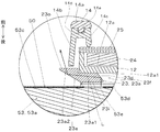
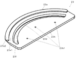
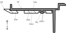
- FIG. 2 is a cross-sectional view taken along line AA of FIG. It is an enlarged view of the range C of FIG. It is a perspective view of the 1st light guide concerning the embodiment of the present invention. It is sectional drawing of the middle case and 1st light guide which concern on embodiment of this invention.
- FIGS. 1 to 5 An embodiment of a display device for a vehicle according to the present invention will be described with reference to FIGS. 1 to 5.
- the direction approaching the driver who is the viewer is defined as the front direction
- the direction separating from the driver is defined as the back direction.
- the display device 10 for a vehicle is, as shown in FIG. 1, a first pointer-type instrument 20 arranged on the right side as viewed from the driver and a second pointer-type instrument 30 arranged on the left side. And a liquid crystal display unit 50 disposed between the first pointer type meter 20 and the second pointer type meter 30, and a control unit 60 for controlling the overall operation of the vehicular display device 10.
- the first pointer-type meter 20 represents the speed of the vehicle by the position of the pointer 21 with respect to a scale (index) 27 formed on the display plate 25.
- the second pointer type meter 30 represents the number of revolutions of the engine by the position of the pointer 31 relative to the scale 37 formed on the display plate 35.
- the liquid crystal display unit 50 displays various vehicle information on the image display surface 53c corresponding to the front surface.
- the rear case 11 is formed of a light shielding resin such as polypropylene.
- the rear case 11 has a box-like shape opened toward the front.
- first and second pointer-type instruments 20, 30 and a liquid crystal display unit 50 are accommodated.
- the circuit board 15 has a substantially rectangular plate shape.
- the circuit board 15 is disposed on the bottom of the rear case 11.
- the circuit board 15 includes a plurality of light sources 22 for illuminating the first and second pointer-type instruments 20 and 30, and a control unit 60 for controlling the liquid crystal display unit 50, the light source 22 and a pointer driving unit 26 described later.
- the light source 22 is configured by an LED (Light Emitting Diode) that emits light of a predetermined color (for example, white).
- the light source 22 is provided on the front surface of the circuit board 15.
- the control unit 60 includes a microcomputer including a central processing unit (CPU), an image processing integrated circuit (IC), a read only memory (ROM), and a random access memory (RAM).
- CPU central processing unit
- IC image processing integrated circuit
- ROM read only memory
- RAM random access memory
- the middle case 12 is disposed on the front surface of the circuit board 15.
- the middle case 12 is formed of a light shielding resin such as polypropylene.
- the middle case 12 includes two housing portions 12 a for respectively storing the display plate 25 of the first pointer type meter 20 and the display plate 35 of the second pointer type meter 30, the pointer 21 and the light from the light source 22. And a plurality of cylindrical portions 12b opening in the front-rear direction so as to lead to the plate 25. Further, as shown in FIG. 5, a plurality of (three in this example) welding pins 12c are formed on the outer bottom surface 12a1 of both the housing portions 12a in order to fix the first light guide 23. .
- the facing member 14 is located in front of the middle case 12.
- the facing member 14 has a shape that hides the area excluding the image display surface 53 c of the liquid crystal display unit 50 and the display plates 25 and 35 of the first and second pointer instruments 20 and 30.
- the facing member 14 is formed of, for example, a light shielding resin.
- the facing member 14 includes a frame portion 14 a located on the outer periphery of the display plate 25 of the first pointer type meter 20 and the display plate 35 of the second pointer type meter 30.
- Each frame portion 14 a includes a partition wall 14 b formed in a range overlapping with the image display surface 53 c of the liquid crystal display unit 50.
- the dividing wall 14b is formed to separate between the display plate 25 and the image display surface 53c excluding the overlapping region 53d described later and between the display plate 35 and the image display surface 53c excluding the overlapping region 53d.
- the partition wall 14b in the vicinity of the display plate 25 is in the vicinity of the rear end of the second light guide 24 in the direction substantially orthogonal to the image display surface 53c. It extends to a position and functions as an outer peripheral surface of the frame portion 14a.
- the partition wall 14b is inclined so as to approach the display plate 25 as it goes forward.
- the front case 13 is fitted in the rear case 11 so as to close the front opening of the rear case 11.
- the front case 13 includes a plate-like window 13a formed of a transparent resin so that the display plates 25 and 35 and the image display surface 53c of the liquid crystal display unit 50 can be viewed from the outside.
- the liquid crystal display unit 50 straddles the first pointer type meter 20 and the second pointer type meter 30 in front of the circuit board 15 and behind the first and second pointer type meters 20 and 30. is set up.
- the liquid crystal display unit 50 includes a liquid crystal display panel 53a and a plurality of light sources 53b.
- Each light source 53 b is configured by an LED that emits light of a predetermined color (for example, white). Each light source 53b is located behind the liquid crystal display panel 53a. Each light source 53 b illuminates the liquid crystal display panel 53 a from the back side.
- the liquid crystal display panel 53a is configured of a TFT type liquid crystal display panel.
- a color filter 53a1 is disposed on each pixel of the liquid crystal display panel 53a.
- the control unit 60 controls the amount of light passing through each pixel of the liquid crystal display panel 53a to display images of a plurality of colors on the image display surface 53c.
- the liquid crystal display unit 50 has a desired color from the light receiving portion facing range 53e of the overlapping area 53d facing the light receiving portion 23i of the first light guide 23 described later. Emits the light L of.
- the first pointer type meter 20 includes first and second light guides 23 and 24 and a pointer driving unit 26.
- the first light guide 23 is provided between the image display surface 53 c of the liquid crystal display panel 53 a and the outer bottom surface 12 a 1 of the accommodation portion 12 a of the middle case 12.
- the first light guide 23 divides light (exemplified by an arrow L in FIG. 3) from the light receiving portion facing area 53e (an area not hatched in FIG. 3) of the image display surface 53c with the dividing wall 14b. Lead to
- the light guide portion 23a is curved along the outer periphery of the display plate 25 and is spaced apart from the image display surface 53c as shown in FIG.
- the light guide portion 23a has a substantially L-shaped cross section. That is, the light guiding portion 23a includes a first portion 23a1 extending along the image display surface 53c of the liquid crystal display panel 53a, and a second portion projecting in a direction away from the image display surface 53c from the outer end of the first portion 23a1. And 23a2.
- the first portion 23a1 is located in an overlapping area 53d where the image display surface 53c and the display plate 25 overlap.
- the second portion 23a2 is located rearward of the partition wall 14b so as to overlap with the partition wall 14b in the front-rear direction. A part of the second portion 23a2 protrudes outward (outside in the radial direction of the display plate 25) than the partition wall 14b.
- the first portion 23a1 of the light guiding portion 23a includes a light receiving portion 23i and a first reflecting surface 23d.
- the light receiving unit 23i faces the light receiving unit facing range 53e of the image display surface 53c so as to be parallel to the image display surface 53c, and receives the light L from the light source 22 that has passed through the light receiving unit facing range 53e.
- the first reflection surface 23 d reflects the light L incident from the light receiving unit 23 i to the outside in the radial direction of the display plate 25.
- the first reflective surface 23 d is inclined radially outward of the display plate 25 as it goes forward.
- a long hole 23 f having an arc shape is formed between the light guide 23 a and the fixed portion 23 b like the light guide 23 a.
- the first reflection surface 23 d corresponds to the side surface of the long hole 23 f on the light guide 23 a side.
- the second portion 23a2 of the light guide portion 23a includes a light output portion 23o and a second reflection surface 23e.
- the second reflection surface 23e is formed on the outer peripheral surface of the second portion 23a2, and reflects the light L reflected by the first reflection surface 23d toward the light output portion 23o located in the front.
- the second reflective surface 23e is inclined radially outward of the display plate 25 as it goes forward.
- the light emitting portion 23o is formed on the front surface of the second portion 23a2, and emits the light L forward including the dividing wall 14b.
- the fixing portion 23b is located on the inner peripheral side of the light guide portion 23a, and is formed in a substantially semicircular plate shape.
- the fixing portion 23b is formed with a plurality of, in this example, three pin through holes 23b1 through which the welding pins 12c of the middle case 12 are inserted.
- the tip of the welding pin 12 c is heat welded.
- the fixing portion 23 b of the first light guide 23 is fixed to the outer bottom surface 12 a 1 of the housing portion 12 a of the middle case 12.
- the fixing method to the inside case 12 of the 1st light guide 23 is not restricted to welding, but an adhesive agent, a hook stop, etc. are arbitrary.
- the second pointer-type meter 30 includes first and second light guides 23 and 24 and a pointer driving unit 26 in addition to the pointer 31 and the display plate 35 described above.
- the functions and configurations of the first and second light guides 23 and 24 of the second pointer type meter 30 and the pointer driving unit 26 are the same as those of the first and second light guides 23 of the first pointer type meter 20,
- the functions and configurations of the twenty-fourth embodiment are substantially the same.
- the control unit 60 controls the pointer driving unit 26 of the first pointer-type meter 20 according to the externally supplied speed signal.
- the pointer driving unit 26 rotates the rotation shaft 26 b by an angle corresponding to the speed according to the control of the control unit 60.
- the pointer 21 is rotated by the rotation of the rotary shaft 26b.
- the driver can know the speed by means of the scale 27 indicated by the pointer 21.
- the scale 27 is illuminated from behind by the second light guide 24.
- the first reflection surface 23 d reflects the light toward the second reflection surface 23 e outward in the radial direction of the display plate 25.
- the second reflective surface 23e reflects light from the first reflective surface 23d forward toward the light output portion 23o. This light is emitted from the first light guide 23 through the light output portion 23o, and the emitted light travels forward. The emitted light is directly or reflected by the section wall 14b to reach the driver. Thereby, the outer peripheral part of the section wall 14b formed in the circumference
- the control unit 60 emits light from the light receiving unit facing range 53e to the first light guide 23 when the degree of importance of the vehicle information displayed on the image display surface 53c excluding the overlapping area 53d is increased.
- the importance of the vehicle information is increased, for example, when the vehicle speed exceeds a threshold value, a preset standard is satisfied, such as when the distance to the intersection where the vehicle turns left or right becomes less than a reference value. Is the case.
- the control unit 60 inputs the operating state of the collision prevention device of the vehicle and the traveling state on the road surface such as lane out as vehicle information through the communication line, and based on this, notifies the driver of the state. Can also emit light.
- the vehicle display device 10 includes the display board 25 on which the scale 27 is displayed, the display board 35 on which the scale 37 is displayed, and the image display surface 53c for displaying an image, and the image display surface 53c is a display board A liquid crystal display panel 53a provided so as to have an overlapping area 53d overlapping with the display plate 25 at a position more rearward than 25; a light source 53b illuminating the liquid crystal display panel 53a; and light received through the liquid crystal display panel 53a from the light source 53b And the first light guide 23 which shines.
- the first light guide 23 is provided between the overlapping area 53 d of the image display surface 53 c and the display plate 25, and the light receiving unit 23 i receives the light from the light source 53 b through the liquid crystal display panel 53 a And a light emitting portion 23o exposed from the display plate 25 to the outer side in the radial direction of the display plate 25 and emitting the light received by the light receiving portion 23i from the first light guide 23.
- the liquid crystal display panel 53a since a part of the display plates 25 and 35 and a part of the liquid crystal display panel 53a overlap in the front-rear direction, a sense of unity of the display plates 25 and 35 and the liquid crystal display panel 53a can be obtained. Further, the liquid crystal display panel 53a does not have to have a shape conforming to the outer shape of the display plates 25 and 35, and the liquid crystal display panel 53a of a general-purpose product can be used in the vehicle display device 10. Furthermore, since the light source for making the 1st light guide 23 shine is unnecessary, the structure of the display apparatus 10 for vehicles can be simplified.
- the display device 10 for vehicles is provided with the division wall 14b which divides between the display boards 25 and 35 and the image display surface 53c except the overlap area
- the light emitting portion 23 o of the first light guide 23 emits light toward the dividing wall 14 b. According to this configuration, light is emitted from the light output portion 23 o of the first light guide 23 to the dividing wall 14 b. Thereby, indirect lighting is realized in the display device 10 for a vehicle, and a three-dimensional effect can be obtained.
- the display plates 25 and 35 have a disk shape, and are arranged side by side in the width direction (left and right direction) so as to sandwich the liquid crystal display panel 53a when viewed from the driver.
- the first light guide 23 has an arc shape along the outer periphery of the display plates 25 and 35, and is provided one each at both edges in the width direction of the image display surface 53c. According to this configuration, in the vehicle display device 10, a sense of unity between the liquid crystal display panel 53a and the pair of display plates 25 and 35 can be obtained. Thus, the appearance of the vehicle display device 10 can be improved.
- the liquid crystal display panel 53a has a color filter 53a1. According to this configuration, the color of the light from the light source 53b that has passed through the liquid crystal display panel 53a is selected by the color filter 53a1. For this reason, the light of the selected color is emitted to the light receiving portion 23i of the first light guide 23, so that the first light guide 23 can emit light in a desired color, and the degree of freedom of illumination Increase.
- the first light guide 23 includes the first and second reflecting surfaces 23d and 23e that reflect light between the light receiving unit 23i and the light emitting unit 23o. According to this configuration, the light receiving portion 23i can be provided at a position hidden by the display plate 25 by the first and second reflecting surfaces 23d and 23e, and the light emitting portion 23o can be easily provided outside the display plate 25. .
- the first light guide 23 is provided with the first and second reflecting surfaces 23d and 23e, but the number of reflecting surfaces is not limited to this and may be one or three or more. Good.
- the first light guide 23 is provided with the first and second reflecting surfaces 23d and 23e, but the number of reflecting surfaces is not limited to this and may be one or three or more. Good.
- the reflecting surfaces 23d and 23e may reflect light at the interface of resin and air, or may reflect light at the interface of a resin and a reflecting layer such as a metal layer formed on the surface.
- the partition wall 14b of the facing member 14 is illustrated as being inclined toward the display plate 25 or 35 as it goes forward, the inclination angle is arbitrary and may not be inclined. Although light is prevented from leaking to the display plates 25 and 35 by the partition wall 14c, the light may be leaked. Moreover, the structure of the whole facing member 14 can be changed suitably.
- control part 60 was making the 1st light guide 23 of both the 1st and 2nd pointer-type instruments 20 and 30 light, either one 1st light guide 23 may be lighted.
- the first light guide 23 may blink in a predetermined cycle.
- the control unit 60 emits light of different light intensities depending on the position of the light receiving unit facing range 53e.
- the control unit 60 may emit different colors depending on the position of the light receiving unit facing range 53e.
- the first light guide 23 is provided so as to overlap with the display plate 25 of the first and second pointer-type instruments 20, 30 in the overlapping area 53d.
- the reference numeral 23 may be provided so as to overlap with a display board other than the first and second pointer-type meters 20, 30, for example, a display board showing only an indicator.
Landscapes
- Physics & Mathematics (AREA)
- Engineering & Computer Science (AREA)
- Chemical & Material Sciences (AREA)
- Nonlinear Science (AREA)
- Combustion & Propulsion (AREA)
- Mechanical Engineering (AREA)
- Transportation (AREA)
- General Physics & Mathematics (AREA)
- Crystallography & Structural Chemistry (AREA)
- Optics & Photonics (AREA)
- Mathematical Physics (AREA)
- Instrument Panels (AREA)
- Details Of Measuring Devices (AREA)
Abstract
車両用表示装置は、目盛りが表される表示板(25)と、画像を表示する画像表示面(53c)を含み、画像表示面(53c)が表示板(25)よりも後方において表示板(25)と重なる重複領域(53d)を有するように設けられる液晶表示パネル(53a)と、液晶表示パネル(53a)を照明する光源と、光源からの液晶表示パネル(53a)を経た光を受けて光輝する第1の導光体(23)と、を備える。第1の導光体(23)は、画像表示面(53c)の重複領域(53d)と表示板(25)の間に設けられ、光源からの液晶表示パネル(53a)を経た光を受光する受光部(23i)と、視認者から見て表示板(25)から表示板(25)の径方向外側に露出し、受光部(23i)により受光された光を第1の導光体(23)から出光する出光部(23o)と、を備える。
Description
本発明は、車両用表示装置に関する。
光源と、光源により照明される液晶表示パネルと、液晶表示パネルの画像表示面に一部が重なり、目盛り部分のみ光を透過させる表示板と、表示板の周囲に位置し、液晶表示パネルを経た光源からの光を受けて光輝する透過部と、を備える車両用表示装置が特許文献1に開示されている。
上記特許文献1に記載の構成においては、透過部を介して液晶表示パネルの画像表示面が運転者に直接的に視認されるおそれがある。このため、車両用表示装置の見栄えについて改善の余地があった。
本発明は、上記実状を鑑みてなされたものであり、見栄えの良い車両用表示装置を提供することを目的とする。
上記目的を達成するため、本発明に係る車両用表示装置は、意匠が表される表示板と、画像を表示する画像表示面を含み、前記画像表示面が前記表示板よりも後方において前記表示板と重なる重複領域を有するように設けられる液晶表示パネルと、前記液晶表示パネルを照明する光源と、前記光源からの前記液晶表示パネルを経た光を受けて光輝する導光体と、を備え、前記導光体は、前記画像表示面の前記重複領域と前記表示板の間に設けられ、前記光源からの前記液晶表示パネルを経た光を受光する受光部と、視認者から見て前記表示板から外側に露出し、前記受光部により受光された光を前記導光体から出光する出光部と、を備える。
上記構成によれば、導光体が設けられているため、液晶表示パネルを経た光源からの光が運転者により直接的に視認されることを抑制できる。従って、見栄えのよい車両用表示装置を提供できる。
本発明に係る車両用表示装置の実施形態について図1~図5を参照して説明する。なお、以下では、車両用表示装置において、視認者である運転者に近づく方向を前方向と規定し、運転者から離れる方向を後方向と規定する。
(構成)
実施の形態に係る車両用表示装置10は、図1に示すように、運転者から見て右側に配列された第1の指針式計器20と、左側に配置された第2の指針式計器30と、第1の指針式計器20と第2の指針式計器30との間に配置された液晶表示ユニット50と、車両用表示装置10全体の動作を制御する制御部60と、を備える。
実施の形態に係る車両用表示装置10は、図1に示すように、運転者から見て右側に配列された第1の指針式計器20と、左側に配置された第2の指針式計器30と、第1の指針式計器20と第2の指針式計器30との間に配置された液晶表示ユニット50と、車両用表示装置10全体の動作を制御する制御部60と、を備える。
第1の指針式計器20は、表示板25に形成された目盛り(指標)27に対する指針21の位置により車両の速度を表す。第2の指針式計器30は、表示板35に形成された目盛り37に対する指針31の位置によりエンジンの回転数を表す。液晶表示ユニット50は、その前面に相当する画像表示面53cに様々な車両情報を表示する。
より詳しくは、車両用表示装置10は、図1のA-A線断面図である図2に示すように、上述した第1及び第2の指針式計器20,30及び液晶表示ユニット50に加えて、後ケース11と、中ケース12と、前ケース13と、見返し部材14と、回路基板15と、を備える。
後ケース11は、ポリプロピレン等の遮光性の樹脂から形成されている。後ケース11は、前方に向けて開口した箱状の形状を有する。後ケース11内には、第1及び第2の指針式計器20,30及び液晶表示ユニット50が収容されている。
回路基板15は、略長方形の板状の形状を有する。回路基板15は、後ケース11の底面に配置されている。回路基板15には、第1及び第2の指針式計器20,30を照明する複数の光源22と、液晶表示ユニット50、光源22及び後述する指針駆動部26を制御する制御部60と、が実装されている。光源22は、所定の色(例えば白色)の光を出射するLED(Light Emitting Diode)により構成されている。光源22は、回路基板15の前面に設けられる。制御部60は、CPU(Central Processing Unit)、画像処理IC(Integrated Circuit)、ROM(Read Only Memory)、RAM(Random Access Memory)を含むマイクロコンピュータから構成される。
中ケース12は、回路基板15の前面に設置されている。中ケース12は、ポリプロピレン等の遮光性の樹脂により形成されている。中ケース12は、第1の指針式計器20の表示板25と第2の指針式計器30の表示板35とをそれぞれ収容する2つの収容部12aと、光源22からの光を指針21及び表示板25に導くように前後方向に開口する複数の筒部12bと、を備える。また、図5に示すように、両収容部12aの外底面12a1には、第1の導光体23を固定するために、複数(本例では3つ)の溶着ピン12cが形成されている。
図1に示すように、見返し部材14は、中ケース12の前方に位置する。見返し部材14は、液晶表示ユニット50の画像表示面53cと第1及び第2の指針式計器20,30の表示板25、35とを除く領域を隠す形状を有する。見返し部材14は、例えば、遮光性の樹脂から形成される。図1及び図2に示すように、見返し部材14は、第1の指針式計器20の表示板25及び第2の指針式計器30の表示板35の外周に位置する枠部14aを備える。各枠部14aは、液晶表示ユニット50の画像表示面53cと重なる範囲に形成された区画壁14bを備える。区画壁14bは、表示板25と後述する重複領域53dを除く画像表示面53cとの間、及び表示板35と重複領域53dを除く画像表示面53cとの間、を区切るように形成される。
図2の領域Cの拡大図である図3に示すように、表示板25近傍の区画壁14bは、画像表示面53cに略直交する方向に、第2の導光体24の後端近傍の位置まで延び、枠部14aの外周面として機能する。一例として、区画壁14bは、前方に向かうにつれて表示板25に近づくように傾斜している。
区画壁14bに隣接して区画壁14cが配置されている。区画壁14cは、表示板25の外周部分に当接して、光の漏れを防ぐ。区画壁14bと区画壁14cとは、その前端部で結合されている。区画壁14bと区画壁14cの接続部分の前面には、窪み14dが形成されている。窪み14dに枠部14aの背面に形成された突部14eが嵌入され、枠部14aと区画壁14b、14cとが結合されている。
なお、第2の指針式計器30の近傍の見返し部材14の構造も図3に示す構造と実質的に同一の構造を有する。
図2に示すように、前ケース13は、後ケース11の前方の開口を塞ぐように後ケース11に嵌め込まれている。前ケース13は、外部から表示板25、35及び液晶表示ユニット50の画像表示面53cを視認できるように透明樹脂により形成された板状の窓部13aを備える。
液晶表示ユニット50は、回路基板15の前方、且つ、第1及び第2の指針式計器20,30の後方に、第1の指針式計器20と第2の指針式計器30に跨がって設置されている。
液晶表示ユニット50は、液晶表示パネル53aと複数の光源53bと、を備える。
各光源53bは、所定の色(例えば白色)の光を出射するLEDにより構成される。各光源53bは、液晶表示パネル53aの後方に位置する。各光源53bは、液晶表示パネル53aを背面側から照明する。
液晶表示パネル53aは、TFT型の液晶表示パネルにより構成される。液晶表示パネル53aの各画素上には、カラーフィルタ53a1が配置されている。制御部60は、液晶表示パネル53aの各画素を透過する光の光量を制御することにより、画像表示面53cに、複数色の画像を表示する。
図1に示すように、液晶表示ユニット50の画像表示面53cは、第1及び第2の指針式計器20,30の表示板25,35と重なる2つの重複領域53dを有する。なお、図1では、識別を容易にするため、2つの重複領域53dに網模様を付して示す。液晶表示ユニット50は、表示板25,35よりも後方に位置するため、その重複領域53dは、表示板25,35により隠される。
図3に示すように、液晶表示ユニット50は、制御部60の制御に従って、重複領域53dのうち後述する第1の導光体23の受光部23iと対向する受光部対向範囲53eから所望の色の光Lを出射する。
第1の指針式計器20は、上述した指針21、光源22及び表示板25に加えて、第1及び第2の導光体23,24と、指針駆動部26と、を備える。
表示板25は、図2に示すように、中ケース12の収容部12aに設置される。表示板25には、図1に示すように、指針21が指し示す円弧状に配列される意匠である目盛り27が形成される。目盛り27は速度を示す。表示板25は、ポリカーボネート等の透光性樹脂からなる円板状の透光性基板と、透光性基板の裏面に形成された遮光層と、を備える。この遮光層は、目盛り27が示す文字、図形又は記号が透光によって表示されるように、目盛り27と重なる部分を除いて形成される。これにより、表示板25の目盛り27は、第2の導光体24から出射した光源22からの光により、背後から照明される。
指針駆動部26は、図2に示すように、回路基板15の後面に設けられるモータ26aと、モータ26aにより回転する円柱状の回転軸26bと、を備える。回転軸26bは、回路基板15に形成される貫通孔を通って回路基板15の前側に突出する。回転軸26bの前端には指針21の基端が装着されている。
図1及び図2に示すように、指針21は、表示板25の径方向に沿って延びる棒状をなし、指針駆動部26により回転軸26bを中心に回転することで、目盛り27を指し示す。指針21は、光源22からの光を受けて光輝する透光性樹脂部材を含む。
図2に示すように、第2の導光体24は、中ケース12の収容部12aに収容され、表示板25の後側に位置する。第2の導光体24は、透光性樹脂により形成される。第2の導光体24は、表示板25とほぼ同一径の円板状の本体部24aと、本体部24aの外周面から光源22に向かって延びる受光部24bと、を備える。光源22から出射した光は、受光部24bに入射し、導光されて本体部24aに入射し、本体部24aから出射する。本体部24aから出射した光の一部が表示板25の目盛り27を透過することで、目盛り27が照明される。
第1の導光体23は、図3に示すように、液晶表示パネル53aの画像表示面53cと中ケース12の収容部12aの外底面12a1との間に設けられている。第1の導光体23は、画像表示面53cの受光部対向範囲53e(図3では、ハッチングを付していない領域)からの光(図3では、矢印Lで例示する)を区画壁14bに導く。
詳しくは、第1の導光体23は、図4に示すように、表示板25の外周側に位置する導光部23aと、導光部23aよりも内周側に位置する固定部23bと、を備える。
導光部23aは表示板25の外周に沿って湾曲し、図3に示すように、画像表示面53cから離間して位置する。導光部23aは、断面略L字状をなす。すなわち、導光部23aは、液晶表示パネル53aの画像表示面53cに沿って延びる第1部分23a1と、この第1部分23a1の外側端部から画像表示面53cから離れる方向に突出する第2部分23a2と、を備える。第1部分23a1は、画像表示面53cと表示板25が重なる重複領域53dに位置する。第2部分23a2は、前後方向において区画壁14bと重なるように、区画壁14bの後方に位置する。第2部分23a2の一部は、区画壁14bよりも外側(表示板25の径方向外側)に突出する。
より詳しくは、導光部23aの第1部分23a1は、受光部23iと、第1の反射面23dと、を備える。
受光部23iは、画像表示面53cと平行をなすように画像表示面53cの受光部対向範囲53eに対面し、その受光部対向範囲53eを通過した光源22からの光Lを受光する。
受光部23iは、画像表示面53cと平行をなすように画像表示面53cの受光部対向範囲53eに対面し、その受光部対向範囲53eを通過した光源22からの光Lを受光する。
第1の反射面23dは、受光部23iから入射した光Lを表示板25の径方向外側に反射する。第1の反射面23dは前方に向かうにつれて表示板25の径方向外側へ傾斜している。ここで、図4に示すように、第1の導光体23において、導光部23aと固定部23bの間に導光部23aと同様に円弧状をなす長孔23fが形成されている。第1の反射面23dは、長孔23fにおける導光部23a側の側面に相当する。
導光部23aの第2部分23a2は、図3に示すように、出光部23oと、第2の反射面23eと、を備える。
第2の反射面23eは、第2部分23a2の外周面に形成され、第1の反射面23dにより反射した光Lを前方に位置する出光部23oに向けて反射する。第2の反射面23eは、前方に向かうにつれて表示板25の径方向外側へ傾斜している。
出光部23oは、第2部分23a2の前面に形成され、光Lを区画壁14bを含む前方に出射する。
固定部23bは、図4に示すように、導光部23aの内周側に位置し、略半円板状に形成される。固定部23bには、中ケース12の溶着ピン12cが挿通される複数、本例では3つのピン通孔23b1が形成されている。図5に示すように、溶着ピン12cがピン通孔23b1に挿通された状態で、溶着ピン12cの先端が熱溶着される。これにより、第1の導光体23の固定部23bは中ケース12の収容部12aの外底面12a1に固定される。なお、第1の導光体23の中ケース12への固定方法は、溶着に限らず、接着剤、フック止め等任意である。
第2の指針式計器30は、前述の指針31と表示板35に加えて、第1及び第2の導光体23,24と、指針駆動部26と、を備える。第2の指針式計器30の第1及び第2の導光体23,24と指針駆動部26の機能と構成は、第1の指針式計器20の第1及び第2の導光体23,24との機能と構成と実質的に同一である。
(動作)
以下、上記構成を有する車両用表示装置10の動作を説明する。
制御部60は、外部から供給される速度信号に従って、第1の指針式計器20の指針駆動部26を制御する。指針駆動部26は、制御部60の制御に従って、回転軸26bを速度に対応する角度だけ回転する。回転軸26bの回転により指針21が回動する。指針21が指し示す目盛り27により、運転者は速度を知ることができる。なお、目盛り27は、第2の導光体24により、背後より照明される。
以下、上記構成を有する車両用表示装置10の動作を説明する。
制御部60は、外部から供給される速度信号に従って、第1の指針式計器20の指針駆動部26を制御する。指針駆動部26は、制御部60の制御に従って、回転軸26bを速度に対応する角度だけ回転する。回転軸26bの回転により指針21が回動する。指針21が指し示す目盛り27により、運転者は速度を知ることができる。なお、目盛り27は、第2の導光体24により、背後より照明される。
同様にして、制御部60は、外部から供給される回転数信号に従って、第2の指針式計器30の指針31の回転角を制御する。指針31が指し示す目盛り37により、運転者はエンジンの回転数を知ることができる。なお、目盛り37は、第2の導光体24により、背後より照明される。
また、制御部60は、液晶表示パネル53aの重複領域53dを除く領域の各画素の透過率を制御し、また、光源53bを制御する。これにより、制御部60は、重複領域53dを除く画像表示面53cに様々な車両情報を表示する。
また、制御部60は、適宜、第1の導光体23を光輝させる。この動作について詳細に説明する。
液晶表示ユニット50は、制御部60による制御に従って、画像表示面53cの受光部対向範囲53eから所望の色の光を出射する。詳しくは、制御部60は、液晶表示パネル53aにおいて、受光部対向範囲53eの画素を光透過状態とし、重複領域53dのうち受光部対向範囲53e以外の画素を光不透過状態、すなわち黒色表示とする。受光部対向範囲53eから出射された光(図3では、符号Lで例示する)は、受光部23iを介して第1の導光体23に入射し、この入射した光は第1の反射面23dに到達する。第1の反射面23dは、この光を第2の反射面23eに向けて表示板25の径方向外側へ反射する。第2の反射面23eは、第1の反射面23dからの光を出光部23oに向けて前方へ反射する。この光は、出光部23oを介して第1の導光体23から出射し、出光した光は前方へ向かう。この出射した光は、直接又は区画壁14bに反射して運転者に到達する。これにより、第1及び第2の指針式計器20,30の周囲に形成された区画壁14bの外周部が照明される。なお、この光は、区画壁14cの作用により、第1及び第2の指針式計器20,30の内部には入り込まない。
液晶表示ユニット50は、制御部60による制御に従って、画像表示面53cの受光部対向範囲53eから所望の色の光を出射する。詳しくは、制御部60は、液晶表示パネル53aにおいて、受光部対向範囲53eの画素を光透過状態とし、重複領域53dのうち受光部対向範囲53e以外の画素を光不透過状態、すなわち黒色表示とする。受光部対向範囲53eから出射された光(図3では、符号Lで例示する)は、受光部23iを介して第1の導光体23に入射し、この入射した光は第1の反射面23dに到達する。第1の反射面23dは、この光を第2の反射面23eに向けて表示板25の径方向外側へ反射する。第2の反射面23eは、第1の反射面23dからの光を出光部23oに向けて前方へ反射する。この光は、出光部23oを介して第1の導光体23から出射し、出光した光は前方へ向かう。この出射した光は、直接又は区画壁14bに反射して運転者に到達する。これにより、第1及び第2の指針式計器20,30の周囲に形成された区画壁14bの外周部が照明される。なお、この光は、区画壁14cの作用により、第1及び第2の指針式計器20,30の内部には入り込まない。
次に、区画壁14bの外周部を照明するタイミングについて説明する。
制御部60は、重複領域53dを除く画像表示面53cに表示される車両情報の重要度が高まった場合に、受光部対向範囲53eから第1の導光体23に光を出射する。車両情報の重要度が高まった場合とは、例えば、車両速度が閾値を超えた場合、車両が右左折する交差点までの距離が基準値以下となった場合等の、予め設定された基準が満たされた場合である。また、制御部60は、車両の衝突防止装置の作動状態や、レーンアウトなどの路面に対する走行状態を車両情報として通信線を介して入力し、これに基づいて運転者に該状態を報知する目的で光を出射させることもできる。
制御部60は、重複領域53dを除く画像表示面53cに表示される車両情報の重要度が高まった場合に、受光部対向範囲53eから第1の導光体23に光を出射する。車両情報の重要度が高まった場合とは、例えば、車両速度が閾値を超えた場合、車両が右左折する交差点までの距離が基準値以下となった場合等の、予め設定された基準が満たされた場合である。また、制御部60は、車両の衝突防止装置の作動状態や、レーンアウトなどの路面に対する走行状態を車両情報として通信線を介して入力し、これに基づいて運転者に該状態を報知する目的で光を出射させることもできる。
(効果)
以上、説明した一実施形態にかかる車両用表示装置10によれば、以下の効果を奏する。
以上、説明した一実施形態にかかる車両用表示装置10によれば、以下の効果を奏する。
(1)車両用表示装置10は、目盛り27が表される表示板25と、目盛り37が表される表示板35と、画像を表示する画像表示面53cを含み、画像表示面53cが表示板25よりも後方において表示板25と重なる重複領域53dを有するように設けられる液晶表示パネル53aと、液晶表示パネル53aを照明する光源53bと、光源53bからの液晶表示パネル53aを経た光を受けて光輝する第1の導光体23と、を備える。第1の導光体23は、画像表示面53cの重複領域53dと表示板25の間に設けられ、光源53bからの液晶表示パネル53aを経た光を受光する受光部23iと、視認者から見て表示板25から表示板25の径方向外側に露出し、受光部23iにより受光された光を第1の導光体23から出光する出光部23oと、を備える。
この構成によれば、第1の導光体23の受光部23iは、画像表示面53cの重複領域53dと表示板25の間に設けられるため、液晶表示パネル53aを経た光源53bからの光が運転者に直接視認されることを抑制できる。このため、第1の導光体23を光輝させた際の車両用表示装置10の見栄えを向上させることができる。
また、表示板25,35の一部と液晶表示パネル53aの一部が前後方向において重なるため、表示板25,35と液晶表示パネル53aの一体感を出すことができる。また、液晶表示パネル53aは、表示板25,35の外形形状に合わせた形状とする必要がなく、車両用表示装置10において汎用品の液晶表示パネル53aを利用することができる。さらに、第1の導光体23を光輝させるための光源が不要となるため、車両用表示装置10の構成を簡素化することができる。
(2)車両用表示装置10は、表示板25、35と重複領域53dを除く画像表示面53cとの間を区画する区画壁14bを備える。第1の導光体23の出光部23oは、光を区画壁14bに向けて出光する。この構成によれば、第1の導光体23の出光部23oから区画壁14bに光が出射される。これにより、車両用表示装置10において間接照明が実現され、立体感を出すことができる。
(3)表示板25,35は、円板状をなし、運転者から見て液晶表示パネル53aを挟み込むように幅方向(左右方向)に並んで配置される。第1の導光体23は、表示板25、35の外周に沿う円弧状をなし、画像表示面53cの幅方向の両縁それぞれに1つずつ設けられる。この構成によれば、車両用表示装置10において液晶表示パネル53aと一対の表示板25、35の一体感を出すことができる。よって、車両用表示装置10の見栄えを向上させることができる。
(4)液晶表示パネル53aは、カラーフィルタ53a1を有する。この構成によれば、カラーフィルタ53a1により、液晶表示パネル53aを経た光源53bからの光の色が選択される。このため、選択された色の光が第1の導光体23の受光部23iに出射されることにより、第1の導光体23を所望の色で発光させることができ、照明の自由度が高まる。
(5)第1の導光体23は、受光部23iと出光部23oとの間に光を反射させる第1及び第2の反射面23d,23eを備える。この構成によれば、第1及び第2の反射面23d,23eにより、受光部23iを表示板25により隠された位置に設け、出光部23oを表示板25の外側に設けることが容易となる。
(6)第1の導光体23の出光部23oは、画像表示面53cから離れた位置に設けられる。この構成によれば、第1の導光体23を光輝させたときに、車両用表示装置10に浮遊感を出すことができる。よって、車両用表示装置10の見栄えを向上させることができる。
(7)液晶表示パネル53aは、重複領域53dのうち第1の導光体23の受光部23iと対向する受光部対向範囲53eを光透過状態とし、重複領域53dのうち受光部対向範囲53e以外の範囲を光不透過状態とする。この構成によれば、運転者により視認される可能性がある重複領域53dのうち受光部対向範囲53e以外の範囲は黒色で表示される。よって、車両用表示装置10の見栄えを向上させることができる。
(変形例)
なお、この発明は上記実施形態に限定されず、適宜変更可能である。
例えば、上記実施形態においては、カラーフィルタ53a1を画素単位で配置する例を示したが、複数の画素に跨がって1つのカラーフィルタ53a1を配置してもよい。例えば、各受光部対向範囲53e上に1つのカラーフィルタが配置されてもよい。さらに、カラーフィルタ53a1は省略されてもよい。
なお、この発明は上記実施形態に限定されず、適宜変更可能である。
例えば、上記実施形態においては、カラーフィルタ53a1を画素単位で配置する例を示したが、複数の画素に跨がって1つのカラーフィルタ53a1を配置してもよい。例えば、各受光部対向範囲53e上に1つのカラーフィルタが配置されてもよい。さらに、カラーフィルタ53a1は省略されてもよい。
上記実施形態においては、第1の導光体23の出光部23oは、画像表示面53cから離れた位置に設けられていたが、画像表示面53cに近い位置に設けられていてもよい。この場合、第1の導光体23の導光部23aは平板状に形成されてもよい。
上記実施形態においては、第1の導光体23の導光部23aは円弧状に形成されていたが、直線状に形成されてもよい。この場合、表示板25は区形状に形成されてもよい。
上記実施形態においては、第1の導光体23は第1及び第2の反射面23d,23eを備えていたが、反射面の数はこれに限らず1つ又は3つ以上であってもよい。
上記実施形態においては、第1の導光体23は第1及び第2の反射面23d,23eを備えていたが、反射面の数はこれに限らず1つ又は3つ以上であってもよい。反射面23d,23eは、樹脂と空気の界面で光を反射する形態でも、樹脂とその表面に形成された金属層等の反射層の界面で光を反射する形態でもよい。
見返し部材14の区画壁14bとして、前方に向かうにつれて表示板25又は35に近づくように傾斜している例を示したが、傾斜角は任意であり、傾斜していなくてもよい。区画壁14cで表示板25,35に光が漏れることを防止したが、光が漏れる構造としてもよい。また、見返し部材14全体の構成は適宜変更可能である。
上記実施形態においては、制御部60は、第1及び第2の指針式計器20,30の両方の第1の導光体23を点灯させていたが、何れか一方の第1の導光体23を点灯させてもよい。また、第1の導光体23を所定の周期で点滅させてもよい。さらに、第1の導光体23はその全域にわたって同一の輝度にて光輝されていたが、その位置によって異なる輝度にて光輝されてもよい。この場合、制御部60は、受光部対向範囲53eの位置によって異なる光強度の光を出射する。
また、第1の導光体23の位置によって異なる色で光輝されてもよい。この場合、制御部60は、受光部対向範囲53eの位置によって異なる色の光を出射する。
また、第1の導光体23の位置によって異なる色で光輝されてもよい。この場合、制御部60は、受光部対向範囲53eの位置によって異なる色の光を出射する。
上記実施形態においては、第1の導光体23は第1及び第2の指針式計器20,30の表示板25と重複領域53dにおいて重なるように設けられていたが、第1の導光体23は第1及び第2の指針式計器20、30以外の表示板、例えばインジケータのみを示す表示板と重なるように設けられていてもよい。
上記実施形態においては、車両用表示装置10は第1及び第2の指針式計器20,30を備えていたが、第1及び第2の指針式計器20,30のうち何れか一方が省略されてもよい。また、第1及び第2の指針式計器20,30が表示する対象は、車両速度、エンジンの回転数に限らず、ガソリン残量、油温、油圧、外気温等であってもよい。
なお、本発明は、本発明の広義の精神と範囲を逸脱することなく、様々な実施形態及び変形が可能とされているものである。また、上述した実施形態は、本発明の一実施例を説明するためのものであり、本発明の範囲を限定するものではない。上記実施例及び変形例は任意に組み合わせることができる。さらに、必要に応じて実施形態の構成要件の一部を除いても本発明の技術的思想の範囲内となる。
本出願は、2017年9月25日に出願された日本国特許出願2017-184107号に基づく。本明細書中に日本国特許出願2017-184107号の明細書、特許請求の範囲、図面全体を参照として取り込むものとする。
10 車両用表示装置
11 後ケース
12 中ケース
12a 収容部
12b 筒部
12c 溶着ピン
13 前ケース
13a 窓部
14 見返し部材
14a 枠部
14b、14c 区画壁
14d 窪み
14e 突部
15 回路基板
20 第1の指針式計器
21、31 指針
22 光源
23 第1の導光体
23a 導光部
23b 固定部
23a1 第1部分
23a2 第2部分
23b1 ピン通孔
23d 第1の反射面
23e 第2の反射面
23f 長孔
23i 受光部
23o 出光部
24 第2の導光体
25 表示板
26 指針駆動部
26a モータ
26b 回転軸
27 目盛り
30 第2の指針式計器
31 指針
35 表示板
37 目盛り
50 液晶表示ユニット
53a 液晶表示パネル
53b 光源
53c 画像表示面
53a1 カラーフィルタ
53d 重複領域
53e 受光部対向範囲
60 制御部
11 後ケース
12 中ケース
12a 収容部
12b 筒部
12c 溶着ピン
13 前ケース
13a 窓部
14 見返し部材
14a 枠部
14b、14c 区画壁
14d 窪み
14e 突部
15 回路基板
20 第1の指針式計器
21、31 指針
22 光源
23 第1の導光体
23a 導光部
23b 固定部
23a1 第1部分
23a2 第2部分
23b1 ピン通孔
23d 第1の反射面
23e 第2の反射面
23f 長孔
23i 受光部
23o 出光部
24 第2の導光体
25 表示板
26 指針駆動部
26a モータ
26b 回転軸
27 目盛り
30 第2の指針式計器
31 指針
35 表示板
37 目盛り
50 液晶表示ユニット
53a 液晶表示パネル
53b 光源
53c 画像表示面
53a1 カラーフィルタ
53d 重複領域
53e 受光部対向範囲
60 制御部
Claims (6)
- 意匠が表される表示板と、
画像を表示する画像表示面を含み、前記画像表示面が前記表示板よりも後方において前記表示板と重なる重複領域を有するように設けられる液晶表示パネルと、
前記液晶表示パネルを照明する光源と、
前記光源からの前記液晶表示パネルを経た光を受けて光輝する導光体と、を備え、
前記導光体は、
前記画像表示面の前記重複領域と前記表示板の間に設けられ、前記光源からの前記液晶表示パネルを経た光を受光する受光部と、
視認者から見て前記表示板から外側に露出し、前記受光部により受光された光を前記導光体から出光する出光部と、を備える、
ことを特徴とする車両用表示装置。 - 前記表示板と前記重複領域を除く前記画像表示面との間を区画する区画壁を備え、
前記導光体の前記出光部は、前記区画壁に向けて光を出光する、
ことを特徴とする請求項1に記載の車両用表示装置。 - 前記表示板は、円板状をなし、視認者から見て前記液晶表示パネルを挟み込むように幅方向に沿って2つ並べられ、
前記導光体は、前記表示板の外周に沿う円弧状をなし、前記画像表示面の前記幅方向の両縁それぞれに1つずつ設けられる、
ことを特徴とする請求項1又は2に記載の車両用表示装置。 - 前記液晶表示パネルは、前記光源からの光に基づき複数の色のうち選択された色の光を生成するカラーフィルタを有する、
ことを特徴とする請求項1から3の何れか一項に記載の車両用表示装置。 - 前記導光体は、前記受光部と前記出光部との間に光を反射させる複数の反射面を備える、
ことを特徴とする請求項1から4の何れか一項に記載の車両用表示装置。 - 前記導光体の前記出光部は、前記画像表示面から離れた位置に設けられる、
ことを特徴とする請求項1から5の何れか一項に記載の車両用表示装置。
Priority Applications (2)
| Application Number | Priority Date | Filing Date | Title |
|---|---|---|---|
| CN201880042409.6A CN110809708B (zh) | 2017-09-25 | 2018-09-21 | 车辆用显示装置 |
| US16/624,638 US10807472B2 (en) | 2017-09-25 | 2018-09-21 | Vehicular display device |
Applications Claiming Priority (2)
| Application Number | Priority Date | Filing Date | Title |
|---|---|---|---|
| JP2017184107A JP6959812B2 (ja) | 2017-09-25 | 2017-09-25 | 車両用表示装置 |
| JP2017-184107 | 2017-09-25 |
Publications (1)
| Publication Number | Publication Date |
|---|---|
| WO2019059367A1 true WO2019059367A1 (ja) | 2019-03-28 |
Family
ID=65810414
Family Applications (1)
| Application Number | Title | Priority Date | Filing Date |
|---|---|---|---|
| PCT/JP2018/035163 Ceased WO2019059367A1 (ja) | 2017-09-25 | 2018-09-21 | 車両用表示装置 |
Country Status (4)
| Country | Link |
|---|---|
| US (1) | US10807472B2 (ja) |
| JP (1) | JP6959812B2 (ja) |
| CN (1) | CN110809708B (ja) |
| WO (1) | WO2019059367A1 (ja) |
Citations (5)
| Publication number | Priority date | Publication date | Assignee | Title |
|---|---|---|---|---|
| JP2006194829A (ja) * | 2005-01-17 | 2006-07-27 | Denso Corp | 車両用表示装置 |
| JP2011099760A (ja) * | 2009-11-06 | 2011-05-19 | Calsonic Kansei Corp | メータ照明構造 |
| JP2016090402A (ja) * | 2014-11-05 | 2016-05-23 | 株式会社デンソー | 車両用表示装置 |
| JP2016531791A (ja) * | 2013-06-24 | 2016-10-13 | デンソー インターナショナル アメリカ インコーポレーテッド | 光ガイド及び車両ダッシュボードディスプレイ |
| JP2017003468A (ja) * | 2015-06-11 | 2017-01-05 | 株式会社デンソー | 表示装置 |
Family Cites Families (7)
| Publication number | Priority date | Publication date | Assignee | Title |
|---|---|---|---|---|
| JP2001066166A (ja) * | 1999-08-27 | 2001-03-16 | Jeco Co Ltd | 計器用表示装置 |
| JP2011123406A (ja) * | 2009-12-14 | 2011-06-23 | Denso Corp | 車両用液晶表示装置 |
| JP5851471B2 (ja) * | 2013-10-15 | 2016-02-03 | 日本精機株式会社 | 指針式計器 |
| JP2015088420A (ja) * | 2013-11-01 | 2015-05-07 | 株式会社デンソー | バックライトユニット |
| JP6363456B2 (ja) * | 2014-09-30 | 2018-07-25 | 矢崎総業株式会社 | 車両用計器 |
| JP6394294B2 (ja) * | 2014-11-05 | 2018-09-26 | 株式会社デンソー | 車両用表示装置 |
| KR101717655B1 (ko) * | 2015-11-30 | 2017-03-17 | 엘지디스플레이 주식회사 | 홀을 구비한 이형 디스플레이 |
-
2017
- 2017-09-25 JP JP2017184107A patent/JP6959812B2/ja active Active
-
2018
- 2018-09-21 CN CN201880042409.6A patent/CN110809708B/zh active Active
- 2018-09-21 WO PCT/JP2018/035163 patent/WO2019059367A1/ja not_active Ceased
- 2018-09-21 US US16/624,638 patent/US10807472B2/en active Active
Patent Citations (5)
| Publication number | Priority date | Publication date | Assignee | Title |
|---|---|---|---|---|
| JP2006194829A (ja) * | 2005-01-17 | 2006-07-27 | Denso Corp | 車両用表示装置 |
| JP2011099760A (ja) * | 2009-11-06 | 2011-05-19 | Calsonic Kansei Corp | メータ照明構造 |
| JP2016531791A (ja) * | 2013-06-24 | 2016-10-13 | デンソー インターナショナル アメリカ インコーポレーテッド | 光ガイド及び車両ダッシュボードディスプレイ |
| JP2016090402A (ja) * | 2014-11-05 | 2016-05-23 | 株式会社デンソー | 車両用表示装置 |
| JP2017003468A (ja) * | 2015-06-11 | 2017-01-05 | 株式会社デンソー | 表示装置 |
Also Published As
| Publication number | Publication date |
|---|---|
| CN110809708B (zh) | 2022-05-24 |
| CN110809708A (zh) | 2020-02-18 |
| JP6959812B2 (ja) | 2021-11-05 |
| JP2019060658A (ja) | 2019-04-18 |
| US10807472B2 (en) | 2020-10-20 |
| US20200215916A1 (en) | 2020-07-09 |
Similar Documents
| Publication | Publication Date | Title |
|---|---|---|
| KR101939506B1 (ko) | 표시 장치 | |
| CN103105188B (zh) | 显示装置 | |
| JP2009210572A (ja) | 計器装置 | |
| JP5846228B2 (ja) | 計器パネル用照明表示装置 | |
| JP6478009B2 (ja) | 表示装置 | |
| JP4895321B2 (ja) | 指示計器 | |
| JP6122694B2 (ja) | 車載用表示装置 | |
| KR20110127650A (ko) | 지침식 계기 | |
| JP4466134B2 (ja) | 表示装置 | |
| JP2009069087A (ja) | 表示装置 | |
| JP5830345B2 (ja) | メータ装置 | |
| WO2016035304A1 (ja) | 表示装置 | |
| CN110809708B (zh) | 车辆用显示装置 | |
| JP2020035546A (ja) | 表示装置 | |
| JP7041840B2 (ja) | 表示装置 | |
| JP2010134276A (ja) | 車両用表示装置 | |
| JP6154210B2 (ja) | 車載用計器 | |
| JP5978841B2 (ja) | 表示装置 | |
| JP2015021751A (ja) | 文字板照明構造 | |
| JP2020134847A (ja) | 導光装置 | |
| JP6601096B2 (ja) | 車両用表示装置 | |
| JP6642239B2 (ja) | 表示装置 | |
| JP2014035324A (ja) | 表示装置 | |
| JP6477046B2 (ja) | 表示装置 | |
| WO2015133143A1 (ja) | 車両用計器 |
Legal Events
| Date | Code | Title | Description |
|---|---|---|---|
| 121 | Ep: the epo has been informed by wipo that ep was designated in this application |
Ref document number: 18859685 Country of ref document: EP Kind code of ref document: A1 |
|
| NENP | Non-entry into the national phase |
Ref country code: DE |
|
| 122 | Ep: pct application non-entry in european phase |
Ref document number: 18859685 Country of ref document: EP Kind code of ref document: A1 |