WO2019059028A1 - 作業車両 - Google Patents
作業車両 Download PDFInfo
- Publication number
- WO2019059028A1 WO2019059028A1 PCT/JP2018/033501 JP2018033501W WO2019059028A1 WO 2019059028 A1 WO2019059028 A1 WO 2019059028A1 JP 2018033501 W JP2018033501 W JP 2018033501W WO 2019059028 A1 WO2019059028 A1 WO 2019059028A1
- Authority
- WO
- WIPO (PCT)
- Prior art keywords
- motor
- disposed
- work vehicle
- vehicle according
- frame
- Prior art date
- Legal status (The legal status is an assumption and is not a legal conclusion. Google has not performed a legal analysis and makes no representation as to the accuracy of the status listed.)
- Ceased
Links
Images



Classifications
-
- B—PERFORMING OPERATIONS; TRANSPORTING
- B60—VEHICLES IN GENERAL
- B60K—ARRANGEMENT OR MOUNTING OF PROPULSION UNITS OR OF TRANSMISSIONS IN VEHICLES; ARRANGEMENT OR MOUNTING OF PLURAL DIVERSE PRIME-MOVERS IN VEHICLES; AUXILIARY DRIVES FOR VEHICLES; INSTRUMENTATION OR DASHBOARDS FOR VEHICLES; ARRANGEMENTS IN CONNECTION WITH COOLING, AIR INTAKE, GAS EXHAUST OR FUEL SUPPLY OF PROPULSION UNITS IN VEHICLES
- B60K17/00—Arrangement or mounting of transmissions in vehicles
- B60K17/34—Arrangement or mounting of transmissions in vehicles for driving both front and rear wheels, e.g. four wheel drive vehicles
- B60K17/354—Arrangement or mounting of transmissions in vehicles for driving both front and rear wheels, e.g. four wheel drive vehicles having separate mechanical assemblies for transmitting drive to the front or to the rear wheels or set of wheels
-
- B—PERFORMING OPERATIONS; TRANSPORTING
- B60—VEHICLES IN GENERAL
- B60K—ARRANGEMENT OR MOUNTING OF PROPULSION UNITS OR OF TRANSMISSIONS IN VEHICLES; ARRANGEMENT OR MOUNTING OF PLURAL DIVERSE PRIME-MOVERS IN VEHICLES; AUXILIARY DRIVES FOR VEHICLES; INSTRUMENTATION OR DASHBOARDS FOR VEHICLES; ARRANGEMENTS IN CONNECTION WITH COOLING, AIR INTAKE, GAS EXHAUST OR FUEL SUPPLY OF PROPULSION UNITS IN VEHICLES
- B60K1/00—Arrangement or mounting of electrical propulsion units
-
- B—PERFORMING OPERATIONS; TRANSPORTING
- B60—VEHICLES IN GENERAL
- B60K—ARRANGEMENT OR MOUNTING OF PROPULSION UNITS OR OF TRANSMISSIONS IN VEHICLES; ARRANGEMENT OR MOUNTING OF PLURAL DIVERSE PRIME-MOVERS IN VEHICLES; AUXILIARY DRIVES FOR VEHICLES; INSTRUMENTATION OR DASHBOARDS FOR VEHICLES; ARRANGEMENTS IN CONNECTION WITH COOLING, AIR INTAKE, GAS EXHAUST OR FUEL SUPPLY OF PROPULSION UNITS IN VEHICLES
- B60K17/00—Arrangement or mounting of transmissions in vehicles
- B60K17/04—Arrangement or mounting of transmissions in vehicles characterised by arrangement, location or kind of gearing
- B60K17/043—Transmission unit disposed in on near the vehicle wheel, or between the differential gear unit and the wheel
-
- B—PERFORMING OPERATIONS; TRANSPORTING
- B60—VEHICLES IN GENERAL
- B60K—ARRANGEMENT OR MOUNTING OF PROPULSION UNITS OR OF TRANSMISSIONS IN VEHICLES; ARRANGEMENT OR MOUNTING OF PLURAL DIVERSE PRIME-MOVERS IN VEHICLES; AUXILIARY DRIVES FOR VEHICLES; INSTRUMENTATION OR DASHBOARDS FOR VEHICLES; ARRANGEMENTS IN CONNECTION WITH COOLING, AIR INTAKE, GAS EXHAUST OR FUEL SUPPLY OF PROPULSION UNITS IN VEHICLES
- B60K17/00—Arrangement or mounting of transmissions in vehicles
- B60K17/04—Arrangement or mounting of transmissions in vehicles characterised by arrangement, location or kind of gearing
- B60K17/16—Arrangement or mounting of transmissions in vehicles characterised by arrangement, location or kind of gearing of differential gearing
-
- B—PERFORMING OPERATIONS; TRANSPORTING
- B60—VEHICLES IN GENERAL
- B60K—ARRANGEMENT OR MOUNTING OF PROPULSION UNITS OR OF TRANSMISSIONS IN VEHICLES; ARRANGEMENT OR MOUNTING OF PLURAL DIVERSE PRIME-MOVERS IN VEHICLES; AUXILIARY DRIVES FOR VEHICLES; INSTRUMENTATION OR DASHBOARDS FOR VEHICLES; ARRANGEMENTS IN CONNECTION WITH COOLING, AIR INTAKE, GAS EXHAUST OR FUEL SUPPLY OF PROPULSION UNITS IN VEHICLES
- B60K17/00—Arrangement or mounting of transmissions in vehicles
- B60K17/22—Arrangement or mounting of transmissions in vehicles characterised by arrangement, location, or type of main drive shafting, e.g. cardan shaft
-
- B—PERFORMING OPERATIONS; TRANSPORTING
- B60—VEHICLES IN GENERAL
- B60K—ARRANGEMENT OR MOUNTING OF PROPULSION UNITS OR OF TRANSMISSIONS IN VEHICLES; ARRANGEMENT OR MOUNTING OF PLURAL DIVERSE PRIME-MOVERS IN VEHICLES; AUXILIARY DRIVES FOR VEHICLES; INSTRUMENTATION OR DASHBOARDS FOR VEHICLES; ARRANGEMENTS IN CONNECTION WITH COOLING, AIR INTAKE, GAS EXHAUST OR FUEL SUPPLY OF PROPULSION UNITS IN VEHICLES
- B60K17/00—Arrangement or mounting of transmissions in vehicles
- B60K17/34—Arrangement or mounting of transmissions in vehicles for driving both front and rear wheels, e.g. four wheel drive vehicles
- B60K17/356—Arrangement or mounting of transmissions in vehicles for driving both front and rear wheels, e.g. four wheel drive vehicles having fluid or electric motor, for driving one or more wheels
-
- B—PERFORMING OPERATIONS; TRANSPORTING
- B60—VEHICLES IN GENERAL
- B60K—ARRANGEMENT OR MOUNTING OF PROPULSION UNITS OR OF TRANSMISSIONS IN VEHICLES; ARRANGEMENT OR MOUNTING OF PLURAL DIVERSE PRIME-MOVERS IN VEHICLES; AUXILIARY DRIVES FOR VEHICLES; INSTRUMENTATION OR DASHBOARDS FOR VEHICLES; ARRANGEMENTS IN CONNECTION WITH COOLING, AIR INTAKE, GAS EXHAUST OR FUEL SUPPLY OF PROPULSION UNITS IN VEHICLES
- B60K6/00—Arrangement or mounting of plural diverse prime-movers for mutual or common propulsion, e.g. hybrid propulsion systems comprising electric motors and internal combustion engines
-
- B—PERFORMING OPERATIONS; TRANSPORTING
- B60—VEHICLES IN GENERAL
- B60K—ARRANGEMENT OR MOUNTING OF PROPULSION UNITS OR OF TRANSMISSIONS IN VEHICLES; ARRANGEMENT OR MOUNTING OF PLURAL DIVERSE PRIME-MOVERS IN VEHICLES; AUXILIARY DRIVES FOR VEHICLES; INSTRUMENTATION OR DASHBOARDS FOR VEHICLES; ARRANGEMENTS IN CONNECTION WITH COOLING, AIR INTAKE, GAS EXHAUST OR FUEL SUPPLY OF PROPULSION UNITS IN VEHICLES
- B60K6/00—Arrangement or mounting of plural diverse prime-movers for mutual or common propulsion, e.g. hybrid propulsion systems comprising electric motors and internal combustion engines
- B60K6/20—Arrangement or mounting of plural diverse prime-movers for mutual or common propulsion, e.g. hybrid propulsion systems comprising electric motors and internal combustion engines the prime-movers consisting of electric motors and internal combustion engines, e.g. HEVs
- B60K6/22—Arrangement or mounting of plural diverse prime-movers for mutual or common propulsion, e.g. hybrid propulsion systems comprising electric motors and internal combustion engines the prime-movers consisting of electric motors and internal combustion engines, e.g. HEVs characterised by apparatus, components or means specially adapted for HEVs
- B60K6/24—Arrangement or mounting of plural diverse prime-movers for mutual or common propulsion, e.g. hybrid propulsion systems comprising electric motors and internal combustion engines the prime-movers consisting of electric motors and internal combustion engines, e.g. HEVs characterised by apparatus, components or means specially adapted for HEVs characterised by the combustion engines
-
- B—PERFORMING OPERATIONS; TRANSPORTING
- B60—VEHICLES IN GENERAL
- B60K—ARRANGEMENT OR MOUNTING OF PROPULSION UNITS OR OF TRANSMISSIONS IN VEHICLES; ARRANGEMENT OR MOUNTING OF PLURAL DIVERSE PRIME-MOVERS IN VEHICLES; AUXILIARY DRIVES FOR VEHICLES; INSTRUMENTATION OR DASHBOARDS FOR VEHICLES; ARRANGEMENTS IN CONNECTION WITH COOLING, AIR INTAKE, GAS EXHAUST OR FUEL SUPPLY OF PROPULSION UNITS IN VEHICLES
- B60K6/00—Arrangement or mounting of plural diverse prime-movers for mutual or common propulsion, e.g. hybrid propulsion systems comprising electric motors and internal combustion engines
- B60K6/20—Arrangement or mounting of plural diverse prime-movers for mutual or common propulsion, e.g. hybrid propulsion systems comprising electric motors and internal combustion engines the prime-movers consisting of electric motors and internal combustion engines, e.g. HEVs
- B60K6/22—Arrangement or mounting of plural diverse prime-movers for mutual or common propulsion, e.g. hybrid propulsion systems comprising electric motors and internal combustion engines the prime-movers consisting of electric motors and internal combustion engines, e.g. HEVs characterised by apparatus, components or means specially adapted for HEVs
- B60K6/26—Arrangement or mounting of plural diverse prime-movers for mutual or common propulsion, e.g. hybrid propulsion systems comprising electric motors and internal combustion engines the prime-movers consisting of electric motors and internal combustion engines, e.g. HEVs characterised by apparatus, components or means specially adapted for HEVs characterised by the motors or the generators
-
- E—FIXED CONSTRUCTIONS
- E02—HYDRAULIC ENGINEERING; FOUNDATIONS; SOIL SHIFTING
- E02F—DREDGING; SOIL-SHIFTING
- E02F3/00—Dredgers; Soil-shifting machines
- E02F3/04—Dredgers; Soil-shifting machines mechanically-driven
- E02F3/76—Graders, bulldozers, or the like with scraper plates or ploughshare-like elements; Levelling scarifying devices
- E02F3/7636—Graders with the scraper blade mounted under the tractor chassis
- E02F3/764—Graders with the scraper blade mounted under the tractor chassis with the scraper blade being pivotable about a vertical axis
-
- E—FIXED CONSTRUCTIONS
- E02—HYDRAULIC ENGINEERING; FOUNDATIONS; SOIL SHIFTING
- E02F—DREDGING; SOIL-SHIFTING
- E02F3/00—Dredgers; Soil-shifting machines
- E02F3/04—Dredgers; Soil-shifting machines mechanically-driven
- E02F3/76—Graders, bulldozers, or the like with scraper plates or ploughshare-like elements; Levelling scarifying devices
- E02F3/7636—Graders with the scraper blade mounted under the tractor chassis
- E02F3/7645—Graders with the scraper blade mounted under the tractor chassis with the scraper blade being pivotable about a horizontal axis disposed parallel to the blade
-
- E—FIXED CONSTRUCTIONS
- E02—HYDRAULIC ENGINEERING; FOUNDATIONS; SOIL SHIFTING
- E02F—DREDGING; SOIL-SHIFTING
- E02F3/00—Dredgers; Soil-shifting machines
- E02F3/04—Dredgers; Soil-shifting machines mechanically-driven
- E02F3/76—Graders, bulldozers, or the like with scraper plates or ploughshare-like elements; Levelling scarifying devices
- E02F3/7636—Graders with the scraper blade mounted under the tractor chassis
- E02F3/7654—Graders with the scraper blade mounted under the tractor chassis with the scraper blade being horizontally movable into a position near the chassis
-
- E—FIXED CONSTRUCTIONS
- E02—HYDRAULIC ENGINEERING; FOUNDATIONS; SOIL SHIFTING
- E02F—DREDGING; SOIL-SHIFTING
- E02F3/00—Dredgers; Soil-shifting machines
- E02F3/04—Dredgers; Soil-shifting machines mechanically-driven
- E02F3/76—Graders, bulldozers, or the like with scraper plates or ploughshare-like elements; Levelling scarifying devices
- E02F3/80—Component parts
- E02F3/84—Drives or control devices therefor, e.g. hydraulic drive systems
- E02F3/844—Drives or control devices therefor, e.g. hydraulic drive systems for positioning the blade, e.g. hydraulically
-
- E—FIXED CONSTRUCTIONS
- E02—HYDRAULIC ENGINEERING; FOUNDATIONS; SOIL SHIFTING
- E02F—DREDGING; SOIL-SHIFTING
- E02F9/00—Component parts of dredgers or soil-shifting machines, not restricted to one of the kinds covered by groups E02F3/00 - E02F7/00
- E02F9/02—Travelling-gear, e.g. associated with slewing gears
-
- E—FIXED CONSTRUCTIONS
- E02—HYDRAULIC ENGINEERING; FOUNDATIONS; SOIL SHIFTING
- E02F—DREDGING; SOIL-SHIFTING
- E02F9/00—Component parts of dredgers or soil-shifting machines, not restricted to one of the kinds covered by groups E02F3/00 - E02F7/00
- E02F9/08—Superstructures; Supports for superstructures
- E02F9/0841—Articulated frame, i.e. having at least one pivot point between two travelling gear units
-
- E—FIXED CONSTRUCTIONS
- E02—HYDRAULIC ENGINEERING; FOUNDATIONS; SOIL SHIFTING
- E02F—DREDGING; SOIL-SHIFTING
- E02F9/00—Component parts of dredgers or soil-shifting machines, not restricted to one of the kinds covered by groups E02F3/00 - E02F7/00
- E02F9/20—Drives; Control devices
- E02F9/202—Mechanical transmission, e.g. clutches, gears
-
- E—FIXED CONSTRUCTIONS
- E02—HYDRAULIC ENGINEERING; FOUNDATIONS; SOIL SHIFTING
- E02F—DREDGING; SOIL-SHIFTING
- E02F9/00—Component parts of dredgers or soil-shifting machines, not restricted to one of the kinds covered by groups E02F3/00 - E02F7/00
- E02F9/20—Drives; Control devices
- E02F9/2058—Electric or electro-mechanical or mechanical control devices of vehicle sub-units
- E02F9/2062—Control of propulsion units
- E02F9/2075—Control of propulsion units of the hybrid type
-
- E—FIXED CONSTRUCTIONS
- E02—HYDRAULIC ENGINEERING; FOUNDATIONS; SOIL SHIFTING
- E02F—DREDGING; SOIL-SHIFTING
- E02F9/00—Component parts of dredgers or soil-shifting machines, not restricted to one of the kinds covered by groups E02F3/00 - E02F7/00
- E02F9/20—Drives; Control devices
- E02F9/22—Hydraulic or pneumatic drives
-
- E—FIXED CONSTRUCTIONS
- E02—HYDRAULIC ENGINEERING; FOUNDATIONS; SOIL SHIFTING
- E02F—DREDGING; SOIL-SHIFTING
- E02F9/00—Component parts of dredgers or soil-shifting machines, not restricted to one of the kinds covered by groups E02F3/00 - E02F7/00
- E02F9/20—Drives; Control devices
- E02F9/22—Hydraulic or pneumatic drives
- E02F9/2253—Controlling the travelling speed of vehicles, e.g. adjusting travelling speed according to implement loads, control of hydrostatic transmission
-
- B—PERFORMING OPERATIONS; TRANSPORTING
- B60—VEHICLES IN GENERAL
- B60K—ARRANGEMENT OR MOUNTING OF PROPULSION UNITS OR OF TRANSMISSIONS IN VEHICLES; ARRANGEMENT OR MOUNTING OF PLURAL DIVERSE PRIME-MOVERS IN VEHICLES; AUXILIARY DRIVES FOR VEHICLES; INSTRUMENTATION OR DASHBOARDS FOR VEHICLES; ARRANGEMENTS IN CONNECTION WITH COOLING, AIR INTAKE, GAS EXHAUST OR FUEL SUPPLY OF PROPULSION UNITS IN VEHICLES
- B60K1/00—Arrangement or mounting of electrical propulsion units
- B60K2001/001—Arrangement or mounting of electrical propulsion units one motor mounted on a propulsion axle for rotating right and left wheels of this axle
-
- B—PERFORMING OPERATIONS; TRANSPORTING
- B60—VEHICLES IN GENERAL
- B60Y—INDEXING SCHEME RELATING TO ASPECTS CROSS-CUTTING VEHICLE TECHNOLOGY
- B60Y2200/00—Type of vehicle
- B60Y2200/40—Special vehicles
- B60Y2200/41—Construction vehicles, e.g. graders, excavators
-
- B—PERFORMING OPERATIONS; TRANSPORTING
- B60—VEHICLES IN GENERAL
- B60Y—INDEXING SCHEME RELATING TO ASPECTS CROSS-CUTTING VEHICLE TECHNOLOGY
- B60Y2200/00—Type of vehicle
- B60Y2200/40—Special vehicles
- B60Y2200/41—Construction vehicles, e.g. graders, excavators
- B60Y2200/411—Bulldozers, Graders
-
- B—PERFORMING OPERATIONS; TRANSPORTING
- B60—VEHICLES IN GENERAL
- B60Y—INDEXING SCHEME RELATING TO ASPECTS CROSS-CUTTING VEHICLE TECHNOLOGY
- B60Y2200/00—Type of vehicle
- B60Y2200/90—Vehicles comprising electric prime movers
- B60Y2200/92—Hybrid vehicles
-
- B—PERFORMING OPERATIONS; TRANSPORTING
- B60—VEHICLES IN GENERAL
- B60Y—INDEXING SCHEME RELATING TO ASPECTS CROSS-CUTTING VEHICLE TECHNOLOGY
- B60Y2400/00—Special features of vehicle units
- B60Y2400/80—Differentials
Definitions
- the present invention relates to a work vehicle.
- Patent Document 1 proposes a front wheel drive device that transmits the output of an engine to two pumps and drives the left and right front wheels by two motors rotated by hydraulic oil supplied from the two pumps. Two motors are arranged in the wheels of the left and right front wheels respectively.
- the present invention has been made in view of the above-described situation, and an object of the present invention is to provide a work vehicle capable of simplifying a front wheel drive device.
- the work vehicle comprises a rear frame, a front frame pivotally attached to the rear frame, a work machine attached to the front frame, a motor disposed on the front frame, and a motor. And a drive shaft connected to the differential.
- the motor is disposed in front of the work machine.
- FIG. 2 Top view showing the configuration of the right front wheel support mechanism Front view showing the configuration of the right front wheel support mechanism Block diagram showing the configuration of the front gear drive of the motor grader
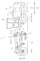
- FIG. 1 is a side view of a motor grader 1.
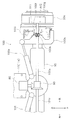
- FIG. 2 is a top view of the motor grader 1.
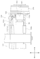
- FIG. 3 is a cross-sectional view taken along the line AA of FIG.
- “upper”, “lower”, “left”, “right”, “front” and “rear” are terms based on the direction viewed from the operator seated at the driver's seat.
- the motor grader 1 is an all-wheel drive vehicle in which all wheels are driven.
- the motor grader 1 includes a frame 10, left and right front wheels 20 and 21, two left and right rear wheels 30, 31, 32 and 33, a work machine 40, a cab 50, an engine 60, and a hydraulic pump 70. , A motor 80, a differential gear 90, and left and right front wheel support mechanisms 100, 101.
- the frame 10 is composed of a front frame 11 and a rear frame 12.
- the front frame 11 is disposed in front of the rear frame 12.
- the front frame 11 is coupled to the rear frame 12.
- the front frame 11 is pivotable to the left and right with respect to the rear frame 12.
- the front frame 11 is supported by the left and right front wheels 20 and 21.
- the front frame 11 supports the work machine 40.
- the front frame 11 has a beam portion 11 a extending in the front-rear direction.
- a motor 80 and a differential gear 90 are disposed at the front end of the beam portion 11a.
- the rear frame 12 is supported by the left and right rear wheels 30, 31, 32, and 33.
- a cab 50, an engine 60 and a hydraulic pump 70 are disposed.
- the work machine 40 is attached to the front frame 11.
- the work implement 40 is disposed below the front frame 11.
- the work implement 40 is disposed between the left and right front wheels 20, 21 and the left and right rear wheels 30, 31, 32, 33 in the front-rear direction.
- the work machine 40 includes a drawbar 41, a blade 42, a blade turning device 43, lifter brackets 44, left and right lift cylinders 45 and 46, and a shift cylinder 47.
- the drawbar 41 is connected to the front end of the front frame 11 so as to be able to swing vertically and horizontally.
- the blade 42 is supported by a blade pivoting device 43.
- the blade pivoting device 43 is attached to the rear end of the drawbar 41.
- the blade turning device 43 has a circle 43a and a circle rotating machine 43b.
- the circle 43 a is rotatably supported at the rear end of the drawbar 41.
- the circle 43 a supports the blade 42.
- the circle rotating machine 43b rotationally drives the circle 43a by hydraulic pressure.
- the lifter bracket 44 is fixed to the frame 10 (specifically, the front frame 11). To the lifter bracket 44, the left and right lift cylinders 45 and 46 and the shift cylinder 47 are connected.
- the left and right lift cylinders 45, 46 are connected to the drawbar 41 and the lifter bracket 44.
- the left and right lift cylinders 45 and 46 swing the drawbar 41 up and down by expanding and contracting.
- the shift cylinder 47 is connected to the drawbar 41 and the lifter bracket 44.
- the shift cylinder 47 swings the drawbar 41 left and right by expansion and contraction.
- the cab 50 is placed on the frame 10.
- the cab 50 is provided with a driver's seat, an operation device, and the like.
- the engine 60 is mounted on the rear frame 12.
- the engine 60 is connected to a rear wheel drive (not shown) (torque converter, transmission, final reduction gear, tandem device, etc.), and the left and right rear wheels 30, 31, 32, 33 are connected via the rear wheel drive. Is driven.
- a hydraulic pump 70 is connected to the engine 60.
- the hydraulic pump 70 is driven by the engine 60.
- the hydraulic pump 70 supplies hydraulic oil to the motor 80.
- As the hydraulic pump 70 for example, a swash plate type or oblique axis type hydraulic pump can be used.
- the motor 80 is accommodated in the tip of the front frame 11 as shown in FIG.
- the motor 80 is fixed on an axle support 95 that houses the differential 90.
- the motor 80 may be disposed outside the front frame 11 or may be disposed at a distance from the axle support 95.
- the motor 80 is connected to the hydraulic pump 70 via a hydraulic oil pipe (not shown).
- the motor 80 is a hydraulic motor driven by hydraulic fluid supplied from the hydraulic pump 70.
- As the motor 80 for example, a radial piston type hydraulic motor can be used, but it is not limited thereto.
- the motor 80 is provided to turn the motor grader 1 smoothly by rotating the front wheels 20, 21 faster than the rear wheels 30, 31, 32, 33.
- the motor 80 is disposed in front of the work implement 40 as shown in FIGS. 1 and 2. Specifically, the motor 80 is disposed forward of the drawbar 41, the blade 42, the blade pivoting device 43, the lifter bracket 44, the left and right lift cylinders 45 and 46, and the shift cylinder 47 which constitute the work machine 40. . As shown in FIG. 2, the motor 80 is disposed such that a portion thereof overlaps the beam portion 11 a of the front frame 11.
- the differential 90 is housed in an axle support 95, as shown in FIG.
- the axle support 95 is attached to the front frame 11 so as to be swingable to the left and right with respect to the differential center of the differential gear 90.
- the differential 90 is drivingly connected to the motor 80.
- the differential device 90 is driven by a motor 80.
- a differential gear 90 is provided to rotate the motor grader 1 smoothly by rotating the outer ring faster than the inner ring.
- the differential device 90 is disposed in front of the work implement 40 as shown in FIGS. 1 and 2. Specifically, the differential gear 90 is disposed in front of each of the drawbar 41, the blade 42, the blade pivoting device 43, the lifter bracket 44, the left and right lift cylinders 45 and 46, and the shift cylinder 47 constituting the work machine 40. ing. As shown in FIG. 2, the differential device 90 is disposed such that a portion thereof overlaps the beam portion 11 a of the front frame 11.
- the differential device 90 is disposed below the motor 80, but is not limited to this.
- the differential device 90 may be disposed at the same position as the motor 80 in the vertical direction, or may be disposed above the motor 80.
- the differential device 90 may be disposed forward of the motor 80 in the front-rear direction, or may be disposed rearward of the motor 80.
- the left and right front wheel support mechanisms 100 and 101 are connected to the left and right of the axle support 95. Since the configurations of the left and right front wheel support mechanisms 100 and 101 are the same, the configuration of the left front wheel support mechanism 100 will be mainly described below.
- FIG. 4 is a top view showing the configuration of left front wheel support mechanism 100.
- FIG. 5 is a front view showing a configuration of left front wheel support mechanism 100. Referring to FIG. In FIG. 5, a cross section of the internal structure is partially shown.
- the left front wheel support mechanism 100 has a left drive shaft 100a, a left constant velocity joint 100b, a left steering cylinder 100c, a tie rod 100d, a left learning cylinder 100e, a left lean housing 100h, and a left hub carrier 100i.
- the left drive shaft 100a extends from the differential 90 towards the left wheel 20a.
- the left drive shaft 100a is connected to the differential 90 and the left constant velocity joint 100b.
- the left drive shaft 100 a is inserted into an axle support 95.
- the right drive shaft 101a is connected to the opposite side of the left drive shaft 100a with the differential device 90 interposed therebetween.
- the left constant velocity joint 100b is disposed in the hub carrier 100i.
- the left constant velocity joint 100b has a connecting shaft 100f.
- the connecting shaft 100 f is connected to the wheel hub 100 g.
- the wheel hub 100g is disposed in a wheel 20a to which the left front wheel 20 is attached.
- the left constant velocity joint 100b is pivotable relative to the left drive shaft 100a about a steering axis AX1 parallel to the vertical direction.
- the left constant velocity joint 100b is pivotable relative to the left drive shaft 100a about a leaning axis AX2 parallel to the front-rear direction.
- the left steering cylinder 100c is connected to the front frame 11 and the left hub carrier 100i. As the left steering cylinder 100c expands and contracts, the left hub carrier 100i swings about the steering axis AX1. Thus, the steering operation of the left front wheel 20 is performed.
- the tie rod 100d is connected to the left hub carrier 100i and a left hub carrier (not shown).
- the left leaning cylinder 100e is connected to the axle support 95 and the left lean housing 100h.
- the left lean housing 100h swings about the leaning axis AX2 by the expansion and contraction of the left leaning cylinder 100e. As a result, a leaning operation of the left front wheel 20 is performed.
- FIG. 6 is a block diagram showing a configuration of front wheel drive device 2 of motor grader 1.
- the front wheel drive 2 includes a controller 120 that controls the pump 70 and the motor 80.
- the controller 120 adjusts the number of rotations of the motor 80 by adjusting the amount of hydraulic fluid supplied from the pump 70 to the motor 80.
- the controller 120 controls the amount of hydraulic fluid supplied from the pump 70 to the motor 80 based on, for example, the turning radius of the motor grader 1, the number of rotations of the left and right rear wheels 30, 31, 32, 33, and the number of rotations of the engine 60. adjust. Specifically, when the motor grader 1 turns left or right, the controller 120 increases the amount of hydraulic fluid supplied from the pump 70 to the motor 80 to make the front wheels 20, 21 the rear wheels 30, 31, 32. , Rotate faster than 33.
- the rotational force of the motor 80 is transmitted to the left and right drive shafts 100 and 101 via the differential device 90. Specifically, when the motor grader 1 turns left or right, the outer ring is rotated faster than the inner ring by adjusting the number of rotations of the left and right drive shafts 100 and 101 by the differential device 90.
- the motor grader 1 since the difference between the inner wheels of the left and right front wheels 20 and 21 can be adjusted by the differential device 90, only one motor 80 may be provided. Further, since the motor 80 is disposed in front of the work implement 40, the motor 80 can be disposed near the differential gear 90. Therefore, the configuration of the front wheel drive 2 can be simplified.
- the motor 80 is disposed on the front frame 11, the exposure of the hydraulic fluid piping connected from the pump 70 to the motor 80 can be suppressed to the outside, so that the hydraulic fluid piping is damaged due to the hit of soil and the like. Can be suppressed.
- the motor 80 is a hydraulic motor driven by hydraulic fluid supplied from the hydraulic pump 70 in the above embodiment, the present invention is not limited to this.
- the motor 80 an electric motor can be used.
- the motor grader 1 may be provided with a generator that is driven by the engine and supplies power to the motor 80.
- the motor grader has been described as an example of a work vehicle to which the front wheel drive device according to the present invention is applied.
- the front wheel drive device according to the present invention can be widely applied to all-wheel drive work vehicles is there.
Landscapes
- Engineering & Computer Science (AREA)
- Mechanical Engineering (AREA)
- Mining & Mineral Resources (AREA)
- Civil Engineering (AREA)
- General Engineering & Computer Science (AREA)
- Structural Engineering (AREA)
- Chemical & Material Sciences (AREA)
- Combustion & Propulsion (AREA)
- Transportation (AREA)
- Motor Power Transmission Devices (AREA)
- Arrangement Or Mounting Of Propulsion Units For Vehicles (AREA)
- Operation Control Of Excavators (AREA)
- Arrangement And Driving Of Transmission Devices (AREA)
Abstract
モータグレーダ(1)は、リヤフレーム(12)と、リヤフレーム(12)に回動可能に連結されるフロントフレーム(11)と、フロントフレーム(11)に取り付けられる作業機(40)と、フロントフレーム(11)に配置されるモータ(80)と、モータ(80)に接続される差動装置(90)と、差動装置(90)に接続される左右のドライブシャフト(100a,101a)とを備える。モータ(80)は、作業機(40)の前方に配置される。
Description
本発明は、作業車両に関する。
従来、左右の後輪を駆動させる後輪駆動装置と、左右の前輪を駆動させる前輪駆動装置とを備えた全輪駆動方式のモータグレーダが知られている。特許文献1では、エンジンの出力を2つのポンプに伝達し、これら2つのポンプから供給される作動油で回転する2つのモータによって左右の前輪それぞれを駆動させる前輪駆動装置が提案されている。2つのモータは、左右の前輪それぞれのホイール内に配置される。
しかしながら、特許文献1に記載の前輪駆動装置では、2つのモータを駆動させるための2つのポンプを設ける必要があるため、車載レイアウトが複雑になってしまう。
本発明は、上述の状況に鑑みてなされたものであり、前輪駆動装置を簡素化可能な作業車両の提供を目的とする。
本発明に係る作業車両は、リヤフレームと、リヤフレームに回動可能に取り付けられたフロントフレームと、フロントフレームに取り付けられた作業機と、フロントフレームに配置されたモータと、モータに駆動連結された差動装置と、差動装置に接続されたドライブシャフトとを備える。モータは、作業機の前方に配置される。
本発明によれば、前輪駆動装置を簡素化可能な作業車両を提供することができる。
(モータグレーダ1の全体構成)
図1は、モータグレーダ1の側面図である。図2は、モータグレーダ1の上面図である。図3は、図2のA-A断面図である。以下の説明において、「上」「下」「左」「右」「前」「後」は、運転席に着座したオペレータから見た方向を基準とする用語である。
図1は、モータグレーダ1の側面図である。図2は、モータグレーダ1の上面図である。図3は、図2のA-A断面図である。以下の説明において、「上」「下」「左」「右」「前」「後」は、運転席に着座したオペレータから見た方向を基準とする用語である。
モータグレーダ1は、全輪が駆動される全輪駆動車両である。モータグレーダ1は、フレーム10と、左右の前輪20,21と、片側二輪ずつ左右の後輪30,31,32,33と、作業機40と、キャブ50と、エンジン60と、油圧ポンプ70と、モータ80と、差動装置90と、左右の前輪支持機構100,101とを備える。
フレーム10は、フロントフレーム11とリヤフレーム12とによって構成される。フロントフレーム11は、リヤフレーム12の前方に配置される。フロントフレーム11は、リヤフレーム12に連結される。フロントフレーム11は、リヤフレーム12に対して左右に回動可能である。フロントフレーム11は、左右の前輪20,21によって支持される。フロントフレーム11は、作業機40を支持する。フロントフレーム11は、前後方向に延びるビーム部11aを有する。ビーム部11aの前方端には、モータ80及び差動装置90が配置される。リヤフレーム12は、左右の後輪30,31,32,33によって支持される。リヤフレーム12には、キャブ50、エンジン60及び油圧ポンプ70が配置される。
作業機40は、フロントフレーム11に取り付けられる。作業機40は、フロントフレーム11の下方に配置される。作業機40は、前後方向において、左右の前輪20,21と左右の後輪30,31,32,33との間に配置される。作業機40は、ドローバ41、ブレード42、ブレード旋回装置43、リフタブラケット44、左右のリフトシリンダ45,46及びシフトシリンダ47を備える。
ドローバ41は、上下左右揺動可能にフロントフレーム11の前端部に連結される。ブレード42は、ブレード旋回装置43に支持される。ブレード旋回装置43は、ドローバ41の後端部に取り付けられる。ブレード旋回装置43は、サークル43a及びサークル回転機43bを有する。サークル43aは、ドローバ41の後端部に回転可能に支持される。サークル43aは、ブレード42を支持する。サークル回転機43bは、油圧によってサークル43aを回転駆動させる。
リフタブラケット44は、フレーム10(具体的には、フロントフレーム11)に固定される。リフタブラケット44には、左右のリフトシリンダ45,46とシフトシリンダ47とが連結される。
左右のリフトシリンダ45,46は、ドローバ41とリフタブラケット44に連結される。左右のリフトシリンダ45,46は、伸縮することによってドローバ41を上下揺動させる。シフトシリンダ47は、ドローバ41とリフタブラケット44とに連結される。シフトシリンダ47は、伸縮することによってドローバ41を左右揺動させる。
キャブ50は、フレーム10上に載置される。キャブ50には、運転席や操作装置などが配置される。エンジン60は、リヤフレーム12上に載置される。エンジン60には、図示しない後輪駆動装置(トルクコンバータ、変速機、終減速装置及びタンデム装置など)が接続されており、後輪駆動装置を介して左右の後輪30,31,32,33が駆動される。エンジン60には、油圧ポンプ70が接続される。油圧ポンプ70は、エンジン60によって駆動される。油圧ポンプ70は、モータ80に作動油を供給する。油圧ポンプ70としては、例えば斜板式あるいは斜軸式の油圧ポンプを用いることができる。
モータ80は、図3に示すように、フロントフレーム11の先端部内に収容される。モータ80は、差動装置90を収容するアクスルサポート95上に固定される。ただし、モータ80は、フロントフレーム11の外に配置されていてもよいし、アクスルサポート95から離れた位置に配置されていてもよい。
モータ80は、図示しない作動油配管を介して油圧ポンプ70に接続される。モータ80は、油圧ポンプ70から供給される作動油によって駆動する油圧モータである。モータ80としては、例えばラジアルピストン式油圧モータを用いることができるが、これに限られるものではない。
ここで、モータグレーダ1が左右いずれかに旋回する場合、内輪差の関係で前輪20,21の旋回半径が後輪30,31,32,33の旋回半径よりも大きくなるため、前輪20,21を後輪30,31,32,33よりも速く回転させる必要がある。そこで、前輪20,21を後輪30,31,32,33よりも速く回転させることによって、モータグレーダ1をスムーズに旋回させるためにモータ80が設けられている。
モータ80は、図1及び図2に示すように、作業機40の前方に配置される。具体的には、モータ80は、作業機40を構成するドローバ41、ブレード42、ブレード旋回装置43、リフタブラケット44、左右のリフトシリンダ45,46及びシフトシリンダ47それぞれよりも前方に配置されている。モータ80は、図2に示すように、その一部がフロントフレーム11のビーム部11aと重なるように配置されている。
差動装置90は、図3に示すように、アクスルサポート95内に収容される。アクスルサポート95は、差動装置90の差動中心を基準として左右揺動可能にフロントフレーム11に取り付けられる。差動装置90は、モータ80に駆動連結されている。差動装置90は、モータ80によって駆動される。
ここで、モータグレーダ1が左右いずれかに旋回する場合、内輪差の関係で前輪21,22のうち外輪の旋回半径が内輪の旋回半径よりも大きくなるため、外輪を内輪よりも速く回転させる必要がある。そこで、外輪を内輪よりも速く回転させることによって、モータグレーダ1をスムーズに旋回させるために差動装置90が設けられている。
差動装置90は、図1及び図2に示すように、作業機40の前方に配置される。具体的には、差動装置90は、作業機40を構成するドローバ41、ブレード42、ブレード旋回装置43、リフタブラケット44、左右のリフトシリンダ45,46及びシフトシリンダ47それぞれよりも前方に配置されている。差動装置90は、図2に示すように、その一部がフロントフレーム11のビーム部11aと重なるように配置されている。
本実施形態において、差動装置90は、モータ80の下方に配置されているが、これに限られるものではない。差動装置90は、上下方向においてモータ80と同等の位置に配置されていてもよいし、モータ80の上方に配置されていてもよい。差動装置90は、前後方向においてモータ80よりも前方に配置されていてもよいし、モータ80よりも後方に配置されていてもよい。
左右の前輪支持機構100,101は、アクスルサポート95の左右に接続される。左右の前輪支持機構100,101それぞれの構成は同じであるため、以下、左前輪支持機構100の構成について主に説明する。
図4は、左前輪支持機構100の構成を示す上面図である。図5は、左前輪支持機構100の構成を示す正面図である。図5では、内部構造の断面が部分的に示されている。
左前輪支持機構100は、左ドライブシャフト100a、左等速ジョイント100b、左ステアリングシリンダ100c、タイロッド100d、左リーニングシリンダ100e、左リーンハウジング100h、及び左ハブキャリア100iを有する。
左ドライブシャフト100aは、差動装置90から左ホイール20aに向かって延びる。左ドライブシャフト100aは、差動装置90と左等速ジョイント100bとに連結される。左ドライブシャフト100aは、アクスルサポート95内に挿通される。なお、差動装置90を挟んで左ドライブシャフト100aの反対側には、右ドライブシャフト101aが連結されている。
左等速ジョイント100bは、ハブキャリア100i内に配置される。左等速ジョイント100bは、連結軸100fを有する。連結軸100fは、ホイールハブ100gに連結される。ホイールハブ100gは、左前輪20が取り付けられるホイール20a内に配置される。左等速ジョイント100bは、上下方向に平行なステアリング軸AX1を中心として、左ドライブシャフト100aに対して揺動可能である。左等速ジョイント100bは、前後方向に平行なリーニング軸AX2を中心として、左ドライブシャフト100aに対して揺動可能である。
左ステアリングシリンダ100cは、フロントフレーム11と左ハブキャリア100iとに連結される。左ステアリングシリンダ100cが伸縮することによって、左ハブキャリア100iがステアリング軸AX1を中心として揺動する。これによって、左前輪20のステアリング操作が行われる。タイロッド100dは、左ハブキャリア100iと図示しない左ハブキャリアとに連結される。
左リーニングシリンダ100eは、アクスルサポート95と左リーンハウジング100hとに連結される。左リーニングシリンダ100eが伸縮することによって、左リーンハウジング100hがリーニング軸AX2を中心として揺動する。これによって、左前輪20のリーニング操作が行われる。
(前輪駆動装置2の構成)
図6は、モータグレーダ1の前輪駆動装置2の構成を示すブロック図である。
図6は、モータグレーダ1の前輪駆動装置2の構成を示すブロック図である。
前輪駆動装置2は、ポンプ70とモータ80とを制御するコントローラ120を備える。コントローラ120は、ポンプ70からモータ80に供給される作動油量を調整することによって、モータ80の回転数を調整する。
コントローラ120は、例えば、モータグレーダ1の旋回半径、左右の後輪30,31,32,33の回転数、及びエンジン60の回転数に基づいてポンプ70からモータ80に供給される作動油量を調整する。具体的には、モータグレーダ1が左右いずれかに旋回する場合、コントローラ120がポンプ70からモータ80に供給される作動油量を増大させることによって、前輪20,21を後輪30,31,32,33よりも速く回転させる。
モータ80の回転力は、差動装置90を介して左右のドライブシャフト100,101に伝達される。具体的には、モータグレーダ1が左右いずれかに旋回する場合、差動装置90が左右のドライブシャフト100,101それぞれの回転数を調整することによって、外輪を内輪よりも速く回転させる。
(特徴)
本実施形態に係るモータグレーダ1では、差動装置90によって左右の前輪20,21の内輪差を調整することができるため、モータ80を1つだけ備えていればよい。また、モータ80は、作業機40の前方に配置されているため、モータ80を差動装置90の近くに配置させることができる。従って、前輪駆動装置2の構成を簡素化することができる。
本実施形態に係るモータグレーダ1では、差動装置90によって左右の前輪20,21の内輪差を調整することができるため、モータ80を1つだけ備えていればよい。また、モータ80は、作業機40の前方に配置されているため、モータ80を差動装置90の近くに配置させることができる。従って、前輪駆動装置2の構成を簡素化することができる。
また、モータ80が、フロントフレーム11に配置されているため、ポンプ70からモータ80に接続される作動油配管の外部への露出を抑えることができるため、土砂などが当たって作動油配管が損傷することを抑制できる。
(他の実施形態)
上記実施形態では、モータ80は、油圧ポンプ70から供給される作動油によって駆動する油圧モータであることとしたが、これに限られるものではない。モータ80としては、電動モータを用いることができる。この場合、モータグレーダ1は、エンジンによって駆動し、モータ80に電力を供給する発電機を備えていればよい。
上記実施形態では、モータ80は、油圧ポンプ70から供給される作動油によって駆動する油圧モータであることとしたが、これに限られるものではない。モータ80としては、電動モータを用いることができる。この場合、モータグレーダ1は、エンジンによって駆動し、モータ80に電力を供給する発電機を備えていればよい。
上記実施形態では、本発明に係る前輪駆動装置を適用した作業車両の一例としてモータグレーダについて説明したが、本発明に係る前輪駆動装置は、全輪駆動方式の作業車両に対して広く適用可能である。
1 モータグレーダ
2 前輪駆動装置
10 フレーム
20,21 左右の前輪
30,31,32,33 左右の後輪
40 作業機
41 ドローバ
42 ブレード
43 ブレード旋回装置
44 リフタブラケット
45,46 左右のリフトシリンダ
47 シフトシリンダ
50 キャブ
60 エンジン
70 油圧ポンプ
80 モータ
90 差動装置
100,101 左右の前輪支持機構
110,111 左右のホイールハブ
2 前輪駆動装置
10 フレーム
20,21 左右の前輪
30,31,32,33 左右の後輪
40 作業機
41 ドローバ
42 ブレード
43 ブレード旋回装置
44 リフタブラケット
45,46 左右のリフトシリンダ
47 シフトシリンダ
50 キャブ
60 エンジン
70 油圧ポンプ
80 モータ
90 差動装置
100,101 左右の前輪支持機構
110,111 左右のホイールハブ
Claims (12)
- リヤフレームと、
前記リヤフレームに回動可能に連結されるフロントフレームと、
前記フロントフレームに取り付けられる作業機と、
前記フロントフレームに配置されるモータと、
前記モータに接続される差動装置と、
前記差動装置に接続されるドライブシャフトと、
を備え、
前記モータは、前記作業機の前方に配置される、
作業車両。 - 前記差動装置は、前記作業機の前方に配置される、
請求項1に記載の作業車両。 - 前記リヤフレームを支持する後輪と、
前記フロントフレームを支持する前輪と、
を備え、
前記作業機は、前記後輪と前記前輪との間に配置される、
請求項1又は2に記載の作業車両。 - 前記作業機は、上下揺動可能に前記フロントフレームに連結されるドローバと、前記ドローバを上下揺動させるリフトシリンダとを有し、
前記モータは、前記リフトシリンダの前方に配置される、
請求項3に記載の作業車両。 - 前記作業機は、前記ドローバに回転可能に支持されるブレード旋回装置を有し、
前記モータは、前記ブレード旋回装置の前方に配置される、
請求項3又は4に記載の作業車両。 - 前記作業機は、前記ブレード旋回装置に支持されるブレードを有し、
前記モータは、前記ブレードの前方に配置される、
請求項5に記載の作業車両。 - 前記フロントフレームは、ビーム部を有し、
前記モータは、前記ビーム部の前方端に配置される、
請求項1乃至6に記載の作業車両。 - 前記モータは、前記差動装置より上方に配置される、
請求項1乃至7に記載の作業車両。 - 前記モータ及び前記差動装置それぞれの少なくとも一部は、上面視において、前記ビーム部と重なるように配置される、
請求項7に記載の作業車両 - エンジンと、
前記エンジンによって駆動される油圧ポンプと、
を備え、
前記モータは、前記油圧ポンプから供給される作動油によって駆動する油圧モータである、
請求項1乃至9のいずれかに記載の作業車両。 - エンジンと、
前記エンジンによって駆動する発電機と、
を備え、
前記モータは、前記発電機から供給される電力によって駆動する電動モータである、
請求項1乃至9のいずれかに記載の作業車両。 - 前記作業車両は、モータグレーダである、
請求項1乃至11のいずれかに記載の作業車両。
Priority Applications (2)
| Application Number | Priority Date | Filing Date | Title |
|---|---|---|---|
| US16/497,663 US20210140139A1 (en) | 2017-09-21 | 2018-09-10 | Work vehicle |
| CN201880024269.XA CN110494317A (zh) | 2017-09-21 | 2018-09-10 | 作业车辆 |
Applications Claiming Priority (2)
| Application Number | Priority Date | Filing Date | Title |
|---|---|---|---|
| JP2017180826A JP6946131B2 (ja) | 2017-09-21 | 2017-09-21 | 作業車両 |
| JP2017-180826 | 2017-09-21 |
Publications (1)
| Publication Number | Publication Date |
|---|---|
| WO2019059028A1 true WO2019059028A1 (ja) | 2019-03-28 |
Family
ID=65810951
Family Applications (1)
| Application Number | Title | Priority Date | Filing Date |
|---|---|---|---|
| PCT/JP2018/033501 Ceased WO2019059028A1 (ja) | 2017-09-21 | 2018-09-10 | 作業車両 |
Country Status (4)
| Country | Link |
|---|---|
| US (1) | US20210140139A1 (ja) |
| JP (1) | JP6946131B2 (ja) |
| CN (1) | CN110494317A (ja) |
| WO (1) | WO2019059028A1 (ja) |
Cited By (1)
| Publication number | Priority date | Publication date | Assignee | Title |
|---|---|---|---|---|
| JP2021055359A (ja) * | 2019-09-30 | 2021-04-08 | 株式会社小松製作所 | モータグレーダ |
Families Citing this family (3)
| Publication number | Priority date | Publication date | Assignee | Title |
|---|---|---|---|---|
| JP7154814B2 (ja) * | 2018-04-26 | 2022-10-18 | 株式会社小松製作所 | 作業機械およびその制御方法 |
| KR102918611B1 (ko) * | 2024-03-20 | 2026-01-30 | 한국생산기술연구원 | 전동 모빌리티의 동력 보조 시스템과, 동력 보조 방법 및 전동 트랙터의 작업기 |
| KR102918610B1 (ko) * | 2024-03-20 | 2026-01-30 | 한국생산기술연구원 | 전동 모빌리티의 동력 보조 시스템과, 동력 보조 방법 및 전동 트랙터의 작업기 |
Citations (3)
| Publication number | Priority date | Publication date | Assignee | Title |
|---|---|---|---|---|
| US20070250236A1 (en) * | 2006-04-20 | 2007-10-25 | Newberry Phillip A | Differential lock control in articulated work machine |
| US20120073890A1 (en) * | 2010-09-24 | 2012-03-29 | Bindl Reginald M | Multi-Worm Circle Drive Gearbox |
| JP2016089615A (ja) * | 2014-10-29 | 2016-05-23 | ジェイ. シー. バンフォード エクスカヴェイターズ リミテッドJ.C. Bamford Excavators Limited | 作業機械 |
Family Cites Families (7)
| Publication number | Priority date | Publication date | Assignee | Title |
|---|---|---|---|---|
| JPH082270A (ja) * | 1994-06-21 | 1996-01-09 | Kanzaki Kokyukoki Mfg Co Ltd | 作業車の四輪駆動装置 |
| CN2505324Y (zh) * | 2001-11-15 | 2002-08-14 | 中外建发展股份有限公司 | 平地机前桥车轮液压驱动装置 |
| CA2417313C (en) * | 2002-01-28 | 2006-04-25 | Deere & Company | Hydrostatic auxiliary drive system |
| CN2755188Y (zh) * | 2004-12-14 | 2006-02-01 | 中外建发展股份有限公司 | 一种具有铲刀升降液压缓冲装置的平地机 |
| CN103522896B (zh) * | 2013-07-30 | 2016-03-30 | 山东临工工程机械有限公司 | 平地机前轮辅助驱动系统 |
| CN103987899B (zh) * | 2013-09-25 | 2015-08-26 | 株式会社小松制作所 | 机动平地机 |
| CN105569108B (zh) * | 2015-12-15 | 2019-04-02 | 湖南三一路面机械有限公司 | 一种平地机传动系统和平地机 |
-
2017
- 2017-09-21 JP JP2017180826A patent/JP6946131B2/ja not_active Expired - Fee Related
-
2018
- 2018-09-10 CN CN201880024269.XA patent/CN110494317A/zh active Pending
- 2018-09-10 WO PCT/JP2018/033501 patent/WO2019059028A1/ja not_active Ceased
- 2018-09-10 US US16/497,663 patent/US20210140139A1/en not_active Abandoned
Patent Citations (3)
| Publication number | Priority date | Publication date | Assignee | Title |
|---|---|---|---|---|
| US20070250236A1 (en) * | 2006-04-20 | 2007-10-25 | Newberry Phillip A | Differential lock control in articulated work machine |
| US20120073890A1 (en) * | 2010-09-24 | 2012-03-29 | Bindl Reginald M | Multi-Worm Circle Drive Gearbox |
| JP2016089615A (ja) * | 2014-10-29 | 2016-05-23 | ジェイ. シー. バンフォード エクスカヴェイターズ リミテッドJ.C. Bamford Excavators Limited | 作業機械 |
Cited By (3)
| Publication number | Priority date | Publication date | Assignee | Title |
|---|---|---|---|---|
| JP2021055359A (ja) * | 2019-09-30 | 2021-04-08 | 株式会社小松製作所 | モータグレーダ |
| JP7262358B2 (ja) | 2019-09-30 | 2023-04-21 | 株式会社小松製作所 | モータグレーダ |
| US12275297B2 (en) | 2019-09-30 | 2025-04-15 | Komatsu Ltd. | Motor grader |
Also Published As
| Publication number | Publication date |
|---|---|
| JP6946131B2 (ja) | 2021-10-06 |
| JP2019055665A (ja) | 2019-04-11 |
| US20210140139A1 (en) | 2021-05-13 |
| CN110494317A (zh) | 2019-11-22 |
Similar Documents
| Publication | Publication Date | Title |
|---|---|---|
| US8640812B2 (en) | Electric drive axle configuration | |
| CN101784433B (zh) | 具有驱动和悬架系统的履带式车辆 | |
| JP6946131B2 (ja) | 作業車両 | |
| US6283237B1 (en) | Method and apparatus for steering articulated machines using variable speed devices | |
| US7562515B2 (en) | Lower limit adjustment mechanism for riding type mower | |
| US11585411B2 (en) | Torque dividing arrangement for a circle drive | |
| US9561715B2 (en) | Wheel hub with electric motor | |
| JP2015042548A (ja) | トラクターの操向装置 | |
| JP2003009607A (ja) | 電動式動力農機 | |
| JP5593449B2 (ja) | トラクター | |
| JP4683569B2 (ja) | ペダルユニット | |
| US9776495B2 (en) | Active mounting system for vehicle transfer case | |
| JP4845209B2 (ja) | ペダルユニット | |
| EP1816058A1 (en) | Multi-purpose lorry with rotating and translating driver's cab | |
| JP2011031661A (ja) | 作業車両 | |
| JP7851230B2 (ja) | 作業車 | |
| JP3489980B2 (ja) | 産業用車両 | |
| JP3551391B2 (ja) | キャビン付転圧ローラ | |
| JP4605658B2 (ja) | 乗用型草刈機 | |
| KR102824172B1 (ko) | 작업 차량 | |
| JP3464129B2 (ja) | 電動駆動式車両 | |
| JP2008179331A (ja) | 農作業機の操向装置 | |
| KR200200480Y1 (ko) | 스키드 로더 | |
| JP2002046494A (ja) | 産業用車両 | |
| JP2025068280A (ja) | 作業車の変速装置 |
Legal Events
| Date | Code | Title | Description |
|---|---|---|---|
| 121 | Ep: the epo has been informed by wipo that ep was designated in this application |
Ref document number: 18859669 Country of ref document: EP Kind code of ref document: A1 |
|
| NENP | Non-entry into the national phase |
Ref country code: DE |
|
| 122 | Ep: pct application non-entry in european phase |
Ref document number: 18859669 Country of ref document: EP Kind code of ref document: A1 |