WO2019054141A1 - 送風装置 - Google Patents
送風装置 Download PDFInfo
- Publication number
- WO2019054141A1 WO2019054141A1 PCT/JP2018/030950 JP2018030950W WO2019054141A1 WO 2019054141 A1 WO2019054141 A1 WO 2019054141A1 JP 2018030950 W JP2018030950 W JP 2018030950W WO 2019054141 A1 WO2019054141 A1 WO 2019054141A1
- Authority
- WO
- WIPO (PCT)
- Prior art keywords
- drive source
- fan
- cylindrical portion
- output shaft
- motor
- Prior art date
- Legal status (The legal status is an assumption and is not a legal conclusion. Google has not performed a legal analysis and makes no representation as to the accuracy of the status listed.)
- Ceased
Links
Images


Classifications
-
- F—MECHANICAL ENGINEERING; LIGHTING; HEATING; WEAPONS; BLASTING
- F04—POSITIVE - DISPLACEMENT MACHINES FOR LIQUIDS; PUMPS FOR LIQUIDS OR ELASTIC FLUIDS
- F04D—NON-POSITIVE-DISPLACEMENT PUMPS
- F04D29/00—Details, component parts, or accessories
- F04D29/26—Rotors specially for elastic fluids
- F04D29/32—Rotors specially for elastic fluids for axial flow pumps
- F04D29/325—Rotors specially for elastic fluids for axial flow pumps for axial flow fans
- F04D29/326—Rotors specially for elastic fluids for axial flow pumps for axial flow fans comprising a rotating shroud
-
- F—MECHANICAL ENGINEERING; LIGHTING; HEATING; WEAPONS; BLASTING
- F04—POSITIVE - DISPLACEMENT MACHINES FOR LIQUIDS; PUMPS FOR LIQUIDS OR ELASTIC FLUIDS
- F04D—NON-POSITIVE-DISPLACEMENT PUMPS
- F04D29/00—Details, component parts, or accessories
- F04D29/40—Casings; Connections of working fluid
- F04D29/52—Casings; Connections of working fluid for axial pumps
- F04D29/54—Fluid-guiding means, e.g. diffusers
- F04D29/541—Specially adapted for elastic fluid pumps
-
- F—MECHANICAL ENGINEERING; LIGHTING; HEATING; WEAPONS; BLASTING
- F04—POSITIVE - DISPLACEMENT MACHINES FOR LIQUIDS; PUMPS FOR LIQUIDS OR ELASTIC FLUIDS
- F04D—NON-POSITIVE-DISPLACEMENT PUMPS
- F04D29/00—Details, component parts, or accessories
- F04D29/40—Casings; Connections of working fluid
- F04D29/52—Casings; Connections of working fluid for axial pumps
- F04D29/522—Casings; Connections of working fluid for axial pumps especially adapted for elastic fluid pumps
-
- F—MECHANICAL ENGINEERING; LIGHTING; HEATING; WEAPONS; BLASTING
- F04—POSITIVE - DISPLACEMENT MACHINES FOR LIQUIDS; PUMPS FOR LIQUIDS OR ELASTIC FLUIDS
- F04D—NON-POSITIVE-DISPLACEMENT PUMPS
- F04D29/00—Details, component parts, or accessories
- F04D29/70—Suction grids; Strainers; Dust separation; Cleaning
- F04D29/701—Suction grids; Strainers; Dust separation; Cleaning especially adapted for elastic fluid pumps
- F04D29/703—Suction grids; Strainers; Dust separation; Cleaning especially adapted for elastic fluid pumps specially for fans, e.g. fan guards
-
- F—MECHANICAL ENGINEERING; LIGHTING; HEATING; WEAPONS; BLASTING
- F04—POSITIVE - DISPLACEMENT MACHINES FOR LIQUIDS; PUMPS FOR LIQUIDS OR ELASTIC FLUIDS
- F04D—NON-POSITIVE-DISPLACEMENT PUMPS
- F04D29/00—Details, component parts, or accessories
- F04D29/70—Suction grids; Strainers; Dust separation; Cleaning
- F04D29/701—Suction grids; Strainers; Dust separation; Cleaning especially adapted for elastic fluid pumps
- F04D29/706—Humidity separation
-
- F—MECHANICAL ENGINEERING; LIGHTING; HEATING; WEAPONS; BLASTING
- F04—POSITIVE - DISPLACEMENT MACHINES FOR LIQUIDS; PUMPS FOR LIQUIDS OR ELASTIC FLUIDS
- F04D—NON-POSITIVE-DISPLACEMENT PUMPS
- F04D19/00—Axial-flow pumps
- F04D19/002—Axial flow fans
Definitions
- the present invention relates to a blower.
- blower that cools a vehicle radiator using a fan.
- the fan is rotated by the power of a drive source, and the radiator is cooled by, for example, sucking air through the radiator (see, for example, Patent Document 1).
- blowers include a shroud that guides the air to the fan.
- the shroud includes a fan arrangement hole for housing the fan, and a drive source attachment portion to which a drive source is attached in the fan arrangement hole as viewed from the air flow direction.
- the drive source attachment portion is formed in a cylindrical shape, for example, following the outer shape of the drive source, and is formed to surround the drive source.
- the drive source attachment portion is provided in the opening when viewed from the air flow direction, the air flow of the fan may be hindered. For this reason, as for a drive source attachment part, it is desirable to have the composition by which inhibition of the ventilation of a fan was controlled. However, the wind speed rises in the vicinity of the drive source attachment by suppressing the inhibition of the air flow from the fan. For this reason, water, such as rain water, may flow around the drive source attachment portion, and the amount of water to be supplied to the drive source enclosed by the drive source attachment portion may increase.
- this invention provides the air blower which can reduce the water contact to a drive source, ensuring the amount of air flow.
- a blower comprises: a drive source having an output shaft and a housing; a fan connected to the output shaft, a fan rotatably driven by the drive source, and a shroud body having a fan arrangement hole for accommodating the fan. And a shroud having a drive source attachment portion provided inside the fan disposition hole as viewed from the axial direction of the output shaft and having the drive source attached thereto, the drive source attachment portion being a periphery of the drive source An inner cylindrical portion surrounding the output shaft in the radial direction, an outer cylindrical portion surrounding the inner cylindrical portion from the outer side in the radial direction, and a plurality of spokes connecting the inner cylindrical portion and the outer cylindrical portion And the inner cylindrical portion includes a ceiling wall that covers the drive source from above in the fixed state of the shroud, and the pressure-side edge of the ceiling wall during rotation of the fan is the housing. Situated in the pressure side than, characterized in that.
- the drive source attachment portion includes the inner cylindrical portion and the outer cylindrical portion connected by the plurality of spokes, air can flow between the inner cylindrical portion and the outer cylindrical portion.
- the inner tubular portion includes the ceiling wall that covers the drive source from above, and the edge on the positive pressure side of the ceiling wall when the fan rotates is positioned on the positive pressure side relative to the housing of the drive source. For this reason, the water which fell from the pressure edge side edge in the top wall part falls to the positive pressure side rather than the housing of the drive source by the air which flows from the negative pressure side toward the positive pressure side. Thereby, the water to the drive source can be reduced. As described above, it is possible to provide an air blower capable of reducing the amount of water to be supplied to the drive source while securing the air flow rate.
- the blower according to the present invention comprises a drive source having an output shaft, a fan connected to the output shaft, and a fan rotatably driven by the drive source, and a shroud main body having a fan arrangement hole for housing the fan, and A shroud having a drive source attachment portion provided inside the fan disposition hole and having the drive source attached thereto when viewed from the axial direction of the output shaft, the fan being formed into a cylindrical shape with a bottom, and A boss portion is disposed to cover the drive source from one side in the axial direction of the output shaft, and the drive source attachment portion is disposed on the other side in the axial direction with respect to the boss portion and the periphery of the drive source An inner cylindrical portion surrounding the output shaft in the radial direction, an outer cylindrical portion surrounding the inner cylindrical portion from the outer side in the radial direction, and a plurality of spokes connecting the inner cylindrical portion and the outer cylindrical portion , With the said inner The outer peripheral surface of the parts, together with the projecting towards the outside in the radial direction of
- the drive source attachment portion since the drive source attachment portion includes the inner cylindrical portion and the outer cylindrical portion connected by the plurality of spokes, air can flow between the inner cylindrical portion and the outer cylindrical portion. As a result, the air flow from the fan is suppressed from being blocked by the drive source attachment portion, and the air flow rate can be secured.
- the outer peripheral surface of the inner cylindrical portion is provided with a protruding portion extending in the circumferential direction while protruding outward in the radial direction.
- the overhanging portion can receive water splashing in the axial direction on the outer side in the radial direction with respect to the outer peripheral surface of the inner cylindrical portion.
- a blower comprises: a drive source having an output shaft and a housing; a fan connected to the output shaft, a fan rotatably driven by the drive source, and a shroud body having a fan arrangement hole for accommodating the fan. And a shroud having a drive source attachment portion provided inside the fan disposition hole and having the drive source attached as viewed from the axial direction of the output shaft, the fan being formed in a cylindrical shape with a bottom And a boss portion disposed to cover the drive source from one side in the axial direction of the output shaft, and the drive source attachment portion is disposed on the other side in the axial direction with respect to the boss portion.
- the inner cylindrical portion includes a ceiling wall that covers the drive source from above in a fixed state of the shroud, and an edge on the positive pressure side of the ceiling wall during rotation of the fan is greater than the housing.
- a protrusion located on the positive pressure side and extending outward in the radial direction of the output shaft and extending in the circumferential direction of the output shaft is formed on the outer peripheral surface of the inner cylindrical portion. It is characterized by
- the drive source attachment portion includes the inner cylindrical portion and the outer cylindrical portion connected by the plurality of spokes, air can flow between the inner cylindrical portion and the outer cylindrical portion.
- the inner tubular portion includes the ceiling wall that covers the drive source from above, and the edge on the positive pressure side of the ceiling wall when the fan rotates is positioned on the positive pressure side relative to the housing of the drive source. For this reason, the water which fell from the pressure edge side edge in the top wall part falls to the positive pressure side rather than the housing of the drive source by the air which flows from the negative pressure side toward the positive pressure side.
- the water to the drive source can be reduced.
- the outer peripheral surface of an inner side cylinder part is provided with the overhang
- the overhanging portion can receive water splashing in the axial direction on the outer side in the radial direction with respect to the outer peripheral surface of the inner cylindrical portion. Therefore, it can suppress that the water which disperses toward an boss
- the air blower which can reduce the water contact to a drive source can be provided, ensuring the amount of air flow.
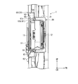
- FIG. 6 is a cross-sectional view taken along the line VI-VI of FIG. 5; It is an expansion perspective view of a blower of an embodiment.
- the blower device 1 of the embodiment is mounted, for example, in an engine room of a car and cools a radiator.
- the radiator is disposed in front of the engine in the engine room, and the blower 1 is attached to the rear of the radiator.
- the blower is disposed between the radiator and the engine.
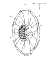
- FIG. 1 is a rear view of the blower of the embodiment as viewed from the rear.
- the blower 1 includes a motor 10 as a drive source, a fan 20 rotationally driven by the motor 10, a shroud 30 forming an outer shell of the blower 1 and fixed to a radiator A heat shield plate 80 which thermally isolates heat from the engine 10 and a wire harness 90 connected to the motor 10 are provided.
- the front, rear, upper, lower, left, and right directions are the same as the front, rear, upper, lower, left, or right directions in a state where the shroud 30 is fixed to the radiator (fixed state of the shroud 30).
- FIG. 2 is a perspective view showing the motor and the fan of the embodiment.
- the motor 10 includes a housing 11 for housing a stator and a rotor (not shown), an output shaft 12 (see FIG. 6) protruding from the housing 11, and a plurality (three in this embodiment) extending from the housing 11 And a motor connector 14 fixed to the housing 11.
- the housing 11 is formed in a cylindrical shape coaxial with the output shaft 12.
- the output shaft 12 extends in the front-rear direction, and protrudes forward from the housing 11 (see FIG. 6). That is, the axial direction of the output shaft 12 coincides with the front-rear direction.
- the plurality of fastening portions 13 extend from the outer peripheral surface of the housing 11 along the radial direction of the output shaft 12 (hereinafter simply referred to as the radial direction).
- the plurality of fastening portions 13 are provided at equal angular intervals in the circumferential direction of the output shaft 12 (hereinafter simply referred to as the circumferential direction).
- Each fastening portion 13 is formed with an insertion hole through which a screw is inserted.
- the motor connector 14 is fixed to the rear end of the housing 11. The motor connector 14 protrudes leftward from the circumferential surface of the housing 11.
- the fan 20 is an axial fan.
- the fan 20 is rotationally driven by the motor 10.
- the fan 20 is driven to suck air through the radiator, and blows the sucked air toward the engine.
- the fan 20 protrudes radially outward from the outer peripheral surface of the boss portion 21 integrally with the bottomed cylindrical boss portion 21 coupled to the output shaft 12 of the motor 10 so as to allow power transmission and the boss portion 21.
- a plurality of (in this embodiment, seven) blades 22 and a cylindrical ring member 23 that annularly connects the radially outer end regions of the plurality of blades 22 are provided.
- the boss portion 21 is provided coaxially with the output shaft 12 of the motor 10.
- the boss portion 21 opens rearward and accommodates the front end portion of the housing 11 of the motor 10 inside.
- Each of the blades 22 is inclined toward the front in the traveling direction of the vehicle as it goes from the rear to the front in the rotational direction of the fan 20 shown by the arrow A in FIG. Therefore, the rear surface of the blade 22 is a positive pressure surface in which the vicinity thereof becomes positive pressure when the fan 20 rotates, and the front surface of the blade 22 is a negative pressure surface in which the vicinity thereof becomes negative pressure when the fan 20 rotates.
- the ring member 23 annularly connects a position offset radially inward from the radially outer end of the blade 22.
- the ring member 23 is provided coaxially with the output shaft 12 of the motor 10.
- FIGS. 3 and Drawing 4 are perspective views showing an air blower of an embodiment.
- the shroud 30 holds the motor 10 and is provided to cover the fan 20 from the outer peripheral side.
- the shroud 30 is a resin molded member, and is molded by injection molding using a mold.
- the shroud 30 is provided in a shroud main body 31 in which a fan disposition hole 33 for disposing the fan 20 is formed, a radiator fixing portion 41 provided in the shroud main body 31 and fixed to a radiator, and the shroud main body 31
- the connector holding portion 48 for holding the connector 92, the main rib 50, the reinforcing rib 52 and the side wall rib 54 erected on the shroud main body 31, and the fan arrangement hole 33 seen from the front and rear direction
- Motor mounting portion 60 (drive source mounting portion) mounted, a plurality of stays 70 connecting the shroud main body 31 and the motor mounting portion 60, and a plurality of heat shield plate mounting seats 72A to which a heat shield plate 80 is mounted 72B and 72C.
- the shroud main body 31 includes a cylindrical portion 32 and an air guide portion 35.
- the cylindrical portion 32 is formed in a cylindrical shape coaxial with the output shaft 12 (see FIG. 6) of the motor 10.
- a fan disposition hole 33 is formed inside the cylindrical portion 32.
- the fan arrangement hole 33 is formed in a circular shape as viewed from the front-rear direction.
- the cylindrical portion 32 surrounds the plurality of blades 22 of the fan 20.
- the air guide 35 guides the air drawn by the fan 20 toward the fan arrangement hole 33.
- the air guide portion 35 includes a flange portion 36 projecting radially outward from the front end edge of the cylindrical portion 32 and a side wall portion 37 extending forward from the outer edge of the flange portion 36.
- the flange portion 36 is formed, for example, in a shape corresponding to the shape of the radiator, and faces the radiator in the front-rear direction. As shown in FIG. 1, the upper end edge of the flange portion 36 extends in the left-right direction. The left and right side edges of the flange portion 36 respectively extend vertically downward from the end portion of the upper end edge of the flange portion 36.
- the lower end edge of the flange portion 36 extends in a circular arc concentric with the output shaft 12 (see FIG. 6) of the motor 10.
- the connection portion between the lower end edge of the flange portion 36 and the left and right side edges is provided below the central axis of the output shaft 12 of the motor 10 and above the lower end of the cylindrical portion 32.
- the side wall 37 extends from the entire outer periphery of the flange 36. That is, the side wall portion 37 includes an upper side wall portion 37a extending from the upper end edge of the flange portion 36, a left side wall portion 37b extending from the left side edge, a right side wall portion 37c extending from the right side edge, and a lower side wall portion extending from the lower end edge And 37d.
- the upper side wall 37a, the left side wall 37b, the right side wall 37c, and the lower side wall 37d are continuous with one another.
- the radiator fixing portion 41 includes an upper fixing portion 42 provided in the upper portion of the shroud main body 31 and lower fixing portions 43A and 43B provided in the lower portion of the shroud main body 31.
- the upper fixed portion 42 is provided in a pair at intervals in the left and right.
- the upper fixing portion 42 protrudes upward from the flange portion 36.
- the upper fixing portion 42 is formed in a triangular shape as viewed from the front and rear direction so that the width in the left and right direction becomes smaller as going from the lower side to the upper side.
- the upper end portion of the upper fixing portion 42 is rounded as viewed in the front-rear direction.
- the upper fixing portion 42 is formed with insertion holes 42 a through which bolts are respectively inserted.
- the lower fixing portions 43A and 43B are provided at intervals in the left and right.
- the lower fixing portions 43A and 43B are a lower left fixing portion 43A provided on the left side and a lower right fixing portion 43B provided on the right side.
- the lower fixing portions 43A and 43B are provided with a boss 44 provided at the lower end portion and projecting downward, and a connecting portion 45 for connecting the boss 44 to the lower side wall portion 37d (see FIG. 3) of the air guiding portion 35. .
- connection portion 45 of each lower fixed portion 43A, 43B is formed of a plurality of flat plate-shaped members extending from the lower side wall portion 37d.
- the connecting portion 45 of the lower left fixing portion 43A includes a first member 45a, a second member 45b, a third member 45c, a fourth member 45d, and a fifth member 45e.
- the first member 45a extends upward from the boss 44 in the vertical direction, and is connected to the lower side wall 37d.
- the second member 45 b extends rightward and upward from the boss 44 and is connected to the lower end portion of the lower side wall portion 37 d.
- the third member 45c extends leftward and upward from the boss 44, and is connected to a connection between the lower side wall 37d and the left side wall 37b (see FIG. 4).
- the fourth member 45 d extends from the middle portion of the first member 45 a to the left and right along the left-right direction.
- the fourth member 45d is connected to the third member 45c at the left end and connected to the lower side wall 37d at the right end.
- the fifth member 45 e extends from the middle portion of the third member 45 c to the right along the left-right direction above the fourth member 45 d and is connected to the lower side wall 37 d.
- the connecting portion 45 of the right lower fixing portion 43B includes a first member 45f, a second member 45g, a third member 45h, a fourth member 45i, a fifth member 45j, and a sixth member 45k.
- the first member 45 f extends upward from the boss 44 in the vertical direction, and is connected to the lower side wall 37 d.
- the second member 45g extends leftward and upward from the boss 44, and is connected to the lower end of the lower side wall 37d.
- the third member 45h extends rightward and upward from the boss 44, and is connected to the connection between the lower side wall 37d and the right side wall 37c.
- the fourth member 45i extends from the middle portion of the first member 45f to the left and right along the left-right direction.
- the fourth member 45i is connected to the third member 45h at the right end and connected to the lower side wall 37d at the left end.
- the fifth member 45 j extends from the middle portion of the third member 45 h to the left and right along the left-right direction above the fourth member 45 i.
- the fifth member 45 j is connected to the third member 45 h at the right end, and is connected to the lower side wall 37 d at the left end.
- the sixth member 45 k extends in the vertical direction from the fourth member 45 i on the left side of the first member 45 f in the vertical direction.
- the sixth member 45 k is connected to the second member 45 g at the lower end portion, and is connected to the lower side wall portion 37 d at the upper end portion.
- the connector holding portion 48 is provided on the side surface of the connecting portion 45 of the lower left fixing portion 43A.
- the connector holding portion 48 is formed in a rectangular box shape.
- the connector holding portion 48 protrudes radially outward from the third member 45 c of the connecting portion 45 of the lower left fixing portion 43A.
- a plurality of main ribs 50 are provided.
- the main rib 50 is erected across the outer peripheral surface of the cylindrical portion 32 and the rear surface of the flange portion 36.
- the main ribs 50 extend radially from the cylindrical portion 32 in the radial direction.
- the main rib 50 is provided more than the stay 70.
- each upper fixing portion 42 a plurality of (three in the present embodiment) reinforcing ribs 52 are provided for each upper fixing portion 42.
- the reinforcing rib 52 is erected across the rear surface of the flange portion 36 and the rear surface of the upper fixing portion 42.
- Each reinforcing rib 52 extends in a straight line.
- At least one of the reinforcing ribs 52 is continuous with the radially inner end of the main rib 50 at the radially inner end.
- the side wall rib 54 is provided upright on the upper side wall 37a.
- the side wall ribs 54 extend in the left-right direction, and are connected to the left and right ends of each upper fixed portion 42.
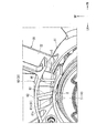
- FIG. 5 is a rear view showing the blower of the embodiment. Note that FIG. 5 illustrates the heat shield plate 80 in a removed state.
- the motor attachment portion 60 is formed to surround the motor 10.
- the motor 10 is fastened and fixed to the motor attachment portion 60.
- the motor mounting portion 60 includes an inner cylindrical portion 61 surrounding the rear end of the housing 11 of the motor 10 from the outer side in the radial direction, an outer cylindrical portion 62 surrounding the inner cylindrical portion 61 from the outer side in the radial direction, and an inner cylindrical portion 61
- a plurality of spokes 63 connecting the outer cylindrical portion 62 and a motor mounting seat 64 to which the motor 10 is attached are provided.
- the inner cylindrical portion 61 is formed in a cylindrical shape coaxial with the output shaft 12 of the motor 10.
- the inner cylindrical portion 61 surrounds the periphery of the rear end portion of the housing 11 of the motor 10. That is, the inner tubular portion 61 surrounds the housing 11 of the motor 10 at the rear of the boss portion 21 of the fan 20.
- the inner cylindrical portion 61 is provided with an enlarged diameter portion 61 a at a position overlapping the motor connector 14 of the motor 10 in the circumferential direction so as to avoid the motor connector 14 of the motor 10.
- the inner cylindrical portion 61 includes a top wall portion 61 b that covers the entire of the motor 10 in the left-right direction from above.
- the top wall 61 b is an upper half of the inner cylindrical portion 61.
- the rear end edge 61 c (the end edge on the positive pressure side) of the top wall portion 61 b is located rearward (on the positive pressure side) than the housing 11 of the motor 10.
- the rear end 61c of the top wall 61b coincides with the rear end of the housing 11 of the motor 10 in the front-rear direction. Also includes the state.
- the top wall portion 61 b overlaps the entire rear end of the housing 11 of the motor 10 as viewed in the vertical direction.
- the rear end edge 61 c of the top wall 61 b is formed at a position that coincides with the rear end of the housing 11 of the motor 10 in the front-rear direction. It is formed in front of the rear end of the housing 11.
- the front end edge of the inner cylindrical portion 61 is formed at the same position in the front-rear direction over the entire circumference.
- the inner cylindrical portion 61 is provided with a protruding portion 66 protruding outward in the radial direction.
- the overhang portion 66 extends in the circumferential direction.
- the overhanging portion 66 is provided forward of an intermediate position in the front-rear direction of the inner cylindrical portion 61 and rearward of the front end edge of the inner cylindrical portion 61.
- the outer diameter of the overhang portion 66 is set to be larger than the inner diameter of the boss portion 21 of the fan 20.
- the overhanging portion 66 may be provided over the entire circumference in the circumferential direction, or may be provided intermittently in the circumferential direction. Even when the overhanging portion 66 is provided intermittently, the outer diameter of the inner cylindrical portion 61 is larger than the inside diameter of the boss portion 21 of the fan 20 even in the portion where the overhanging portion 66 is not provided. It is desirable that the
- the outer cylindrical portion 62 is formed in a cylindrical shape larger in diameter than the inner cylindrical portion 61 and coaxial with the output shaft 12 of the motor 10.
- the outer cylindrical portion 62 is arranged with a space in the radial direction with respect to the inner cylindrical portion 61.
- the front end edge of the outer cylindrical portion 62 is formed at the same position in the front-rear direction as the front end edge of the inner cylindrical portion 61 over the entire circumference.
- the rear end edge of the outer cylindrical portion 62 is formed at the same position in the front-rear direction as the rear end edge 61 c of the top wall portion 61 b of the inner cylindrical portion 61 over the entire circumference.
- the plurality of spokes 63 are formed in a plate shape extending in the front-rear direction.
- the plurality of spokes 63 are connected to the outer peripheral surface of the inner cylindrical portion 61 and the inner peripheral surface of the outer cylindrical portion 62, respectively.
- the plurality of spokes 63 are arranged such that at least a portion thereof is separated from the adjacent spokes 63 respectively.
- each spoke 63 is formed at the same position as the front end edge of the inner cylindrical portion 61 and the outer cylindrical portion 62 in the front-rear direction.
- the radially inner end is formed at the same position as the rear end edge of the lower half of the inner cylindrical portion 61 in the front-rear direction.
- the radially outer end is formed at the same position as the rear end edge of the outer cylindrical portion 62 in the front-rear direction.
- the motor mounting seats 64 are provided in the same number (three in the present embodiment) as the plurality of fastening portions 13 (see FIG. 2) of the motor 10. Each motor mounting seat 64 is provided at a position corresponding to the plurality of fastening portions 13 of the motor 10. Each motor mounting seat 64 is connected to the inner cylindrical portion 61 and the outer cylindrical portion 62. Each motor mounting seat 64 is formed to fill the space between the adjacent spokes 63 in the circumferential direction when viewed from the front-rear direction.
- the fastening portion 13 of the motor 10 is disposed on the front of each motor mounting seat 64 from the front, and is fastened and fixed by screws.
- the plurality of stays 70 radially extend from the outer cylindrical portion 62 of the motor attachment portion 60 along the radial direction.
- the radially outer end of each stay 70 is continuous with the radially inner end of the main rib 50 of the shroud body 31.
- a plurality of heat shield plate mounting seats 72A, 72B, 72C are provided on the shroud main body 31 and the motor mounting portion 60.
- the plurality of heat shield plate mounting seats 72A, 72B, 72C are a first mounting seat 72A provided on the shroud main body 31, and a second mounting seat 72B and a third mounting seat 72C provided on the motor mounting portion 60. is there.
- the plurality of heat shield plate mounting seats 72A, 72B, 72C are formed in a cylindrical shape protruding rearward.
- the plurality of heat shield plate mounting seats 72A, 72B, 72C are provided at positions corresponding to heat shield plate fixing portions 83 described later of the heat shield plate 80, respectively.
- the heat shield plate 80 is disposed so as to cover a part of the fan disposition hole 33 of the shroud main body 31 and at least a part of the motor 10 from the rear.
- the heat shield plate 80 is formed of, for example, a single metal plate by press molding or the like.
- the heat shield plate 80 includes a main plate 81 facing the fan 20 in the front-rear direction, a side wall 82 extending forward from a part of the outer edge of the main plate 81, and a heat shield plate fixing portion 83 fixed to the shroud 30. And.
- the main plate 81 is formed in a flat plate shape extending perpendicularly to the front-rear direction.
- the main plate 81 is formed with a front surface orthogonal to the front-rear direction and facing the blades 22 of the fan 20.
- the main plate 81 includes a diameter inner portion 85 overlapping with the motor 10 when viewed from the front and rear direction, and a diameter outer portion 86 extending from the diameter inner portion 85 along the predetermined radial direction to the outer side of the cylindrical portion 32 of the shroud main body .
- the boundary between the radially inner portion 85 and the radially outer portion 86 matches the inner circumferential surface of the inner cylindrical portion 61 of the motor attachment portion 60 as viewed in the front-rear direction.
- the main plate 81 is provided with a plurality of beads 81 a.
- the plurality of beads 81 a extend parallel to each other along the predetermined radial direction across the radial inner portion 85 and the radial outer portion 86.
- the radial inner portion 85 is formed to cover most of the motor 10 as viewed in the front-rear direction.
- the radial inside 85 thermally isolates the motor 10 from the engine disposed behind the blower 1.
- the upper portion of the radial inner portion 85 protrudes to a position radially outward of the inner peripheral surface of the inner cylindrical portion 61 and radially inward of the outer cylindrical portion 62 when viewed in the front-rear direction.
- the lower right portion of the inner diameter portion 85 is formed to expose the inner side of the inner cylindrical portion 61 when viewed in the front-rear direction.
- the radial outer portion 86 blocks the flow of the air sent by the fan 20 in the front-rear direction at a position behind (on the pressure side) the fan 20.
- the radially outer portion 86 includes both side edges 86a and 86c extending along the predetermined radial direction, and a leading edge 86b connecting the both sides 86a and 86c at the tip of the radially outer portion 86.
- the side edges 86 a and 86 c are a rear edge 86 a facing rearward in the rotational direction of the fan 20 (the direction indicated by arrow A in the drawing) and a front edge 86 c facing forward in the rotational direction of the fan 20.
- the rear side edge 86 a extends forward in the rotational direction of the fan 20 from the radially inner side toward the outer side.
- the front edge 86c extends rearward in the rotational direction as it goes from the inner side to the outer side in the radial direction.
- the leading edge 86 b connects the radially outer end of the rear edge 86 a and the radially outer end of the front edge 86 c.
- the leading end edge 86 b extends in a direction substantially orthogonal to the predetermined radial direction.
- the leading edge 86 b is disposed outside the fan disposition hole 33 of the shroud body 31.
- the side wall 82 extends forward from the outer edge of the radial outer portion 86 along the front-rear direction.
- the side wall 82 suppresses the wind received by the main plate 81 from flowing out of the space in front of the main plate 81.
- the side wall 82 includes a first side wall 82 a extending from the rear side edge 86 a of the radial outside 86, a second side wall 82 b extending from the entire leading edge 86 b of the radial outside 86, and a third side extending from the front side 86 c of the radial outside 86. And a side wall 82c.
- the first side wall 82 a extends from a portion of the rear side edge 86 a of the radial outer portion 86 ranging from the radial middle portion to the radial inner end portion.
- the radially outer end of the first side wall 82 a is provided radially outward of the outer cylindrical portion 62 of the motor attachment portion 60.
- the second side wall 82b and the third side wall 82c are continuous with each other.
- the third side wall 82c follows the shape of the front edge 86c of the radial outer portion 86, and proceeds radially inward from the radially outer side as advancing from the rear to the front in the rotational direction of the fan 20.
- the heat shield plate 80 has a portion where the side wall 82 is not provided on the rear side of the main plate 81 in the rotational direction of the fan 20.
- the communication portion 88 communicating with the rotation direction of the fan 20 is formed in the first side wall 82a.
- the heat shield plate fixing portion 83 includes a first heat shield plate fixing portion 83 a fixed to the shroud main body 31, a second heat shield plate fixing portion 83 b fixed to the motor mounting portion 60, and a third heat shield plate fixing portion 83 c. And have.
- the heat shield fixing portion 83 extends from the side edge of the main plate 81 toward the front, and then protrudes outward in the radial direction.
- the heat shield plate fixing portion 83 is formed with an insertion hole through which a screw is inserted.
- the first heat shield plate fixing portion 83 a is provided at the radially outer end of the radial outer portion 86. A portion of the first heat shield plate fixing portion 83a is shared with the second side wall 82b.
- the first heat shield plate fixing portion 83 a is fastened and fixed to a first mounting seat 72 ⁇ / b> A provided on the shroud main body 31.
- the second heat shield plate fixing portion 83 b is provided at an end of the heat shield plate 80 opposite to the first heat shield plate fixing portion 83 a.
- the second heat shield plate fixing portion 83 b is a motor attachment portion 60. It is fastened and fixed to the 2nd attachment seat 72B provided in.
- the third heat shield plate fixing portion 83 c is provided at the radially inner end portion of the radial outside 86. A part of the third heat shield plate fixing portion 83c is shared with the first side wall 82a.
- the third heat shield plate fixing portion 83 c is fastened and fixed to a third mounting seat 72 ⁇ / b> C provided in the motor mounting portion 60.
- the connector 91 at one end is connected to the motor connector 14 of the motor 10, and the connector 92 at the other end is held by the connector holding portion 48 (see FIG. 4).
- the wire harness 90 is disposed between the inner cylindrical portion 61 and the outer cylindrical portion 62 of the motor mounting portion 60 in order from one end to the other end, and then the heat shield plate 80 (see FIG. It extends radially outward while being held by a stay 70 provided at a position overlapping with 1).
- the operation of the air blower 1 of the present embodiment will be described.
- the blower 1 by rotating the fan 20, the wind flows from the front toward the rear through the inside of the fan arrangement hole 33.
- a motor attachment portion 60 is provided inside the fan arrangement hole 33 as viewed from the front-rear direction.
- the motor attachment portion 60 since the motor attachment portion 60 includes the inner cylindrical portion 61 and the outer cylindrical portion 62 connected by the plurality of spokes 63, air can be supplied between the inner cylindrical portion 61 and the outer cylindrical portion 62. It becomes possible to flow. This prevents the air from the fan 20 from being blocked by the motor attachment portion 60, and the amount of air can be secured.
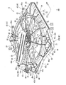
- FIG. 7 is an enlarged perspective view of the air blower of the embodiment. Note that FIG. 7 shows a state in which a part of the shroud 30 is broken and the heat shield plate 80 is removed.
- the inner cylindrical portion 61 of the motor mounting portion 60 includes a top wall portion 61 b that covers the motor 10 from above, and the rear end edge 61 c of the top wall portion 61 b is located rearward of the housing 11 of the motor 10. For this reason, as shown by arrow B in FIG. 7, the water falling from the rear end edge 61 c of the top wall 61 b falls to the rear than the housing 11 of the motor 10 by the air flowing from the front to the rear. . Thus, the water on the motor 10 can be reduced.
- an overhanging portion 66 is provided which extends outward in the radial direction and extends along the circumferential direction.
- the overhanging portion 66 can receive water that splashes in the front-rear direction outside the outer circumferential surface of the inner cylindrical portion 61 in the radial direction. Therefore, it is possible to suppress water splashed from the inner cylindrical portion 61 side in the front-rear direction toward the boss portion 21 of the fan 20 from entering between the boss portion 21 and the motor 10. Thus, the water on the motor 10 can be reduced.
- the air blower 1 capable of reducing the amount of water on the motor 10 while securing the air flow rate.
- blower is used for cooling the radiator in the above embodiment
- blower according to the present invention is not limited to the radiator cooling, and may be for cooling other devices. .
- the air blower is disposed on the vehicle rear side of the radiator, but the air blower may be disposed on the vehicle front side of the radiator and the air blower may be disposed to supply the air blown out to the radiator. .
Landscapes
- Engineering & Computer Science (AREA)
- Mechanical Engineering (AREA)
- General Engineering & Computer Science (AREA)
- Structures Of Non-Positive Displacement Pumps (AREA)
Priority Applications (1)
| Application Number | Priority Date | Filing Date | Title |
|---|---|---|---|
| US16/625,759 US11143202B2 (en) | 2017-09-14 | 2018-08-22 | Blower device |
Applications Claiming Priority (2)
| Application Number | Priority Date | Filing Date | Title |
|---|---|---|---|
| JP2017176751A JP6787860B2 (ja) | 2017-09-14 | 2017-09-14 | 送風装置 |
| JP2017-176751 | 2017-09-14 |
Publications (1)
| Publication Number | Publication Date |
|---|---|
| WO2019054141A1 true WO2019054141A1 (ja) | 2019-03-21 |
Family
ID=65723997
Family Applications (1)
| Application Number | Title | Priority Date | Filing Date |
|---|---|---|---|
| PCT/JP2018/030950 Ceased WO2019054141A1 (ja) | 2017-09-14 | 2018-08-22 | 送風装置 |
Country Status (3)
| Country | Link |
|---|---|
| US (1) | US11143202B2 (enExample) |
| JP (1) | JP6787860B2 (enExample) |
| WO (1) | WO2019054141A1 (enExample) |
Families Citing this family (6)
| Publication number | Priority date | Publication date | Assignee | Title |
|---|---|---|---|---|
| US9388072B2 (en) | 2013-06-25 | 2016-07-12 | Carboncure Technologies Inc. | Methods and compositions for concrete production |
| US9376345B2 (en) | 2013-06-25 | 2016-06-28 | Carboncure Technologies Inc. | Methods for delivery of carbon dioxide to a flowable concrete mix |
| CA2943791C (en) | 2014-04-07 | 2023-09-05 | Carboncure Technologies Inc. | Integrated carbon dioxide capture |
| EP3442761B1 (en) | 2016-04-11 | 2025-12-10 | Carboncure Technologies Inc. | Method of preparing a concrete mix |
| WO2020217232A1 (en) | 2019-04-26 | 2020-10-29 | Carboncure Technologies Inc. | Carbonation of concrete aggregates |
| JP7757266B2 (ja) * | 2022-11-16 | 2025-10-21 | 株式会社ミツバ | ファン装置 |
Citations (4)
| Publication number | Priority date | Publication date | Assignee | Title |
|---|---|---|---|---|
| JPH0683993U (ja) * | 1993-05-24 | 1994-12-02 | カルソニック株式会社 | 電動ファン装置 |
| JP2000110773A (ja) * | 1998-10-07 | 2000-04-18 | Sanyo Denki Co Ltd | 防水構造を備えた送風機 |
| JP2010132183A (ja) * | 2008-12-05 | 2010-06-17 | Mitsubishi Heavy Ind Ltd | 車両用熱交換モジュールおよびこれを備えた車両 |
| JP2017110563A (ja) * | 2015-12-16 | 2017-06-22 | 株式会社デンソー | 送風装置 |
Family Cites Families (9)
| Publication number | Priority date | Publication date | Assignee | Title |
|---|---|---|---|---|
| JPH0683993A (ja) | 1992-08-31 | 1994-03-25 | Hiroshi Aoyama | 国際時刻計 |
| US6874990B2 (en) * | 2003-01-29 | 2005-04-05 | Siemens Vdo Automotive Inc. | Integral tip seal in a fan-shroud structure |
| JP5636788B2 (ja) * | 2009-08-03 | 2014-12-10 | 日本電産株式会社 | 送風ファン |
| US9618281B2 (en) * | 2010-04-22 | 2017-04-11 | Denso International America, Inc. | Heat exchange device |
| WO2012096247A1 (ja) * | 2011-01-11 | 2012-07-19 | 株式会社ミツバ | 電動ファン |
| JP6156061B2 (ja) | 2013-10-29 | 2017-07-05 | 株式会社デンソー | 送風装置 |
| JP6126984B2 (ja) * | 2013-12-18 | 2017-05-10 | 山洋電気株式会社 | 防水型軸流ファン |
| JP6564130B2 (ja) * | 2016-03-30 | 2019-09-04 | 株式会社ミツバ | 冷却ファン装置 |
| DE102016221642A1 (de) * | 2016-11-04 | 2018-05-09 | Brose Fahrzeugteile GmbH & Co. Kommanditgesellschaft, Würzburg | Zargenvorrichtung für ein Kühlerlüftermodul, ein Kühlerlüftermodul mit einer Zargenvorrichtung und Fahrzeug mit einem solchen Kühlerlüftermodul |
-
2017
- 2017-09-14 JP JP2017176751A patent/JP6787860B2/ja active Active
-
2018
- 2018-08-22 WO PCT/JP2018/030950 patent/WO2019054141A1/ja not_active Ceased
- 2018-08-22 US US16/625,759 patent/US11143202B2/en active Active
Patent Citations (4)
| Publication number | Priority date | Publication date | Assignee | Title |
|---|---|---|---|---|
| JPH0683993U (ja) * | 1993-05-24 | 1994-12-02 | カルソニック株式会社 | 電動ファン装置 |
| JP2000110773A (ja) * | 1998-10-07 | 2000-04-18 | Sanyo Denki Co Ltd | 防水構造を備えた送風機 |
| JP2010132183A (ja) * | 2008-12-05 | 2010-06-17 | Mitsubishi Heavy Ind Ltd | 車両用熱交換モジュールおよびこれを備えた車両 |
| JP2017110563A (ja) * | 2015-12-16 | 2017-06-22 | 株式会社デンソー | 送風装置 |
Also Published As
| Publication number | Publication date |
|---|---|
| JP6787860B2 (ja) | 2020-11-18 |
| JP2019052575A (ja) | 2019-04-04 |
| US11143202B2 (en) | 2021-10-12 |
| US20200124054A1 (en) | 2020-04-23 |
Similar Documents
| Publication | Publication Date | Title |
|---|---|---|
| WO2019054141A1 (ja) | 送風装置 | |
| WO2019054140A1 (ja) | 送風装置 | |
| JP2013142374A (ja) | 送風装置 | |
| US10823042B2 (en) | Air blowing fan device | |
| EP3109484A1 (en) | Air-blowing device | |
| WO2017170029A1 (ja) | 冷却ファン装置のファンシュラウド | |
| JP2020156268A (ja) | モータユニット | |
| JP2009109103A (ja) | 熱交換モジュール | |
| US10298085B2 (en) | Motor support unit and heating, ventilation and/or air conditioning installation for a corresponding motor vehicle | |
| JP2007023964A (ja) | 送風装置 | |
| JP2022119091A (ja) | ファンシュラウド及び送風装置 | |
| JP2009156176A (ja) | 冷却装置 | |
| JP2009191627A (ja) | 電動ファン装置 | |
| JP6900282B2 (ja) | 送風装置 | |
| JP2006207379A (ja) | 送風ファン | |
| JP5270902B2 (ja) | 電動ファン装置 | |
| JP4644994B2 (ja) | 送風装置 | |
| JP6181908B2 (ja) | ブロワ | |
| JP2008303830A (ja) | ファン装置 | |
| JP2009171751A (ja) | ファンモータ | |
| JP7270433B2 (ja) | モータユニット | |
| KR200345445Y1 (ko) | 자동차냉각팬용팬슈라우드 | |
| JP4285265B2 (ja) | 放熱器の冷却装置 | |
| JP2009257266A (ja) | ファンシュラウド | |
| JP2024100305A (ja) | 送風装置 |
Legal Events
| Date | Code | Title | Description |
|---|---|---|---|
| 121 | Ep: the epo has been informed by wipo that ep was designated in this application |
Ref document number: 18855344 Country of ref document: EP Kind code of ref document: A1 |
|
| NENP | Non-entry into the national phase |
Ref country code: DE |
|
| 122 | Ep: pct application non-entry in european phase |
Ref document number: 18855344 Country of ref document: EP Kind code of ref document: A1 |