WO2019049575A1 - 計測機能付き軸受 - Google Patents
計測機能付き軸受 Download PDFInfo
- Publication number
- WO2019049575A1 WO2019049575A1 PCT/JP2018/029225 JP2018029225W WO2019049575A1 WO 2019049575 A1 WO2019049575 A1 WO 2019049575A1 JP 2018029225 W JP2018029225 W JP 2018029225W WO 2019049575 A1 WO2019049575 A1 WO 2019049575A1
- Authority
- WO
- WIPO (PCT)
- Prior art keywords
- bearing
- measurement function
- heat flow
- function according
- flow sensor
- Prior art date
- Legal status (The legal status is an assumption and is not a legal conclusion. Google has not performed a legal analysis and makes no representation as to the accuracy of the status listed.)
- Ceased
Links
Images




Classifications
-
- F—MECHANICAL ENGINEERING; LIGHTING; HEATING; WEAPONS; BLASTING
- F16—ENGINEERING ELEMENTS AND UNITS; GENERAL MEASURES FOR PRODUCING AND MAINTAINING EFFECTIVE FUNCTIONING OF MACHINES OR INSTALLATIONS; THERMAL INSULATION IN GENERAL
- F16C—SHAFTS; FLEXIBLE SHAFTS; ELEMENTS OR CRANKSHAFT MECHANISMS; ROTARY BODIES OTHER THAN GEARING ELEMENTS; BEARINGS
- F16C19/00—Bearings with rolling contact, for exclusively rotary movement
- F16C19/52—Bearings with rolling contact, for exclusively rotary movement with devices affected by abnormal or undesired conditions
- F16C19/525—Bearings with rolling contact, for exclusively rotary movement with devices affected by abnormal or undesired conditions related to temperature and heat, e.g. insulation
-
- F—MECHANICAL ENGINEERING; LIGHTING; HEATING; WEAPONS; BLASTING
- F16—ENGINEERING ELEMENTS AND UNITS; GENERAL MEASURES FOR PRODUCING AND MAINTAINING EFFECTIVE FUNCTIONING OF MACHINES OR INSTALLATIONS; THERMAL INSULATION IN GENERAL
- F16C—SHAFTS; FLEXIBLE SHAFTS; ELEMENTS OR CRANKSHAFT MECHANISMS; ROTARY BODIES OTHER THAN GEARING ELEMENTS; BEARINGS
- F16C33/00—Parts of bearings; Special methods for making bearings or parts thereof
- F16C33/30—Parts of ball or roller bearings
- F16C33/58—Raceways; Race rings
- F16C33/62—Selection of substances
-
- F—MECHANICAL ENGINEERING; LIGHTING; HEATING; WEAPONS; BLASTING
- F16—ENGINEERING ELEMENTS AND UNITS; GENERAL MEASURES FOR PRODUCING AND MAINTAINING EFFECTIVE FUNCTIONING OF MACHINES OR INSTALLATIONS; THERMAL INSULATION IN GENERAL
- F16C—SHAFTS; FLEXIBLE SHAFTS; ELEMENTS OR CRANKSHAFT MECHANISMS; ROTARY BODIES OTHER THAN GEARING ELEMENTS; BEARINGS
- F16C33/00—Parts of bearings; Special methods for making bearings or parts thereof
- F16C33/72—Sealings
- F16C33/76—Sealings of ball or roller bearings
- F16C33/762—Sealings of ball or roller bearings by means of a fluid
- F16C33/763—Sealings of ball or roller bearings by means of a fluid retained in the sealing gap
- F16C33/765—Sealings of ball or roller bearings by means of a fluid retained in the sealing gap by a magnetic field
-
- F—MECHANICAL ENGINEERING; LIGHTING; HEATING; WEAPONS; BLASTING
- F16—ENGINEERING ELEMENTS AND UNITS; GENERAL MEASURES FOR PRODUCING AND MAINTAINING EFFECTIVE FUNCTIONING OF MACHINES OR INSTALLATIONS; THERMAL INSULATION IN GENERAL
- F16C—SHAFTS; FLEXIBLE SHAFTS; ELEMENTS OR CRANKSHAFT MECHANISMS; ROTARY BODIES OTHER THAN GEARING ELEMENTS; BEARINGS
- F16C41/00—Other accessories, e.g. devices integrated in the bearing not relating to the bearing function as such
- F16C41/004—Electro-dynamic machines, e.g. motors, generators, actuators
-
- F—MECHANICAL ENGINEERING; LIGHTING; HEATING; WEAPONS; BLASTING
- F16—ENGINEERING ELEMENTS AND UNITS; GENERAL MEASURES FOR PRODUCING AND MAINTAINING EFFECTIVE FUNCTIONING OF MACHINES OR INSTALLATIONS; THERMAL INSULATION IN GENERAL
- F16C—SHAFTS; FLEXIBLE SHAFTS; ELEMENTS OR CRANKSHAFT MECHANISMS; ROTARY BODIES OTHER THAN GEARING ELEMENTS; BEARINGS
- F16C41/00—Other accessories, e.g. devices integrated in the bearing not relating to the bearing function as such
- F16C41/007—Encoders, e.g. parts with a plurality of alternating magnetic poles
-
- F—MECHANICAL ENGINEERING; LIGHTING; HEATING; WEAPONS; BLASTING
- F16—ENGINEERING ELEMENTS AND UNITS; GENERAL MEASURES FOR PRODUCING AND MAINTAINING EFFECTIVE FUNCTIONING OF MACHINES OR INSTALLATIONS; THERMAL INSULATION IN GENERAL
- F16C—SHAFTS; FLEXIBLE SHAFTS; ELEMENTS OR CRANKSHAFT MECHANISMS; ROTARY BODIES OTHER THAN GEARING ELEMENTS; BEARINGS
- F16C41/00—Other accessories, e.g. devices integrated in the bearing not relating to the bearing function as such
- F16C41/008—Identification means, e.g. markings, RFID-tags; Data transfer means
-
- G—PHYSICS
- G01—MEASURING; TESTING
- G01P—MEASURING LINEAR OR ANGULAR SPEED, ACCELERATION, DECELERATION, OR SHOCK; INDICATING PRESENCE, ABSENCE, OR DIRECTION, OF MOVEMENT
- G01P3/00—Measuring linear or angular speed; Measuring differences of linear or angular speeds
- G01P3/42—Devices characterised by the use of electric or magnetic means
- G01P3/44—Devices characterised by the use of electric or magnetic means for measuring angular speed
- G01P3/443—Devices characterised by the use of electric or magnetic means for measuring angular speed mounted in bearings
-
- F—MECHANICAL ENGINEERING; LIGHTING; HEATING; WEAPONS; BLASTING
- F16—ENGINEERING ELEMENTS AND UNITS; GENERAL MEASURES FOR PRODUCING AND MAINTAINING EFFECTIVE FUNCTIONING OF MACHINES OR INSTALLATIONS; THERMAL INSULATION IN GENERAL
- F16C—SHAFTS; FLEXIBLE SHAFTS; ELEMENTS OR CRANKSHAFT MECHANISMS; ROTARY BODIES OTHER THAN GEARING ELEMENTS; BEARINGS
- F16C19/00—Bearings with rolling contact, for exclusively rotary movement
- F16C19/02—Bearings with rolling contact, for exclusively rotary movement with bearing balls essentially of the same size in one or more circular rows
- F16C19/04—Bearings with rolling contact, for exclusively rotary movement with bearing balls essentially of the same size in one or more circular rows for radial load mainly
- F16C19/06—Bearings with rolling contact, for exclusively rotary movement with bearing balls essentially of the same size in one or more circular rows for radial load mainly with a single row or balls
-
- F—MECHANICAL ENGINEERING; LIGHTING; HEATING; WEAPONS; BLASTING
- F16—ENGINEERING ELEMENTS AND UNITS; GENERAL MEASURES FOR PRODUCING AND MAINTAINING EFFECTIVE FUNCTIONING OF MACHINES OR INSTALLATIONS; THERMAL INSULATION IN GENERAL
- F16C—SHAFTS; FLEXIBLE SHAFTS; ELEMENTS OR CRANKSHAFT MECHANISMS; ROTARY BODIES OTHER THAN GEARING ELEMENTS; BEARINGS
- F16C19/00—Bearings with rolling contact, for exclusively rotary movement
- F16C19/02—Bearings with rolling contact, for exclusively rotary movement with bearing balls essentially of the same size in one or more circular rows
- F16C19/14—Bearings with rolling contact, for exclusively rotary movement with bearing balls essentially of the same size in one or more circular rows for both radial and axial load
- F16C19/18—Bearings with rolling contact, for exclusively rotary movement with bearing balls essentially of the same size in one or more circular rows for both radial and axial load with two or more rows of balls
- F16C19/181—Bearings with rolling contact, for exclusively rotary movement with bearing balls essentially of the same size in one or more circular rows for both radial and axial load with two or more rows of balls with angular contact
- F16C19/183—Bearings with rolling contact, for exclusively rotary movement with bearing balls essentially of the same size in one or more circular rows for both radial and axial load with two or more rows of balls with angular contact with two rows at opposite angles
- F16C19/184—Bearings with rolling contact, for exclusively rotary movement with bearing balls essentially of the same size in one or more circular rows for both radial and axial load with two or more rows of balls with angular contact with two rows at opposite angles in O-arrangement
- F16C19/186—Bearings with rolling contact, for exclusively rotary movement with bearing balls essentially of the same size in one or more circular rows for both radial and axial load with two or more rows of balls with angular contact with two rows at opposite angles in O-arrangement with three raceways provided integrally on parts other than race rings, e.g. third generation hubs
-
- F—MECHANICAL ENGINEERING; LIGHTING; HEATING; WEAPONS; BLASTING
- F16—ENGINEERING ELEMENTS AND UNITS; GENERAL MEASURES FOR PRODUCING AND MAINTAINING EFFECTIVE FUNCTIONING OF MACHINES OR INSTALLATIONS; THERMAL INSULATION IN GENERAL
- F16C—SHAFTS; FLEXIBLE SHAFTS; ELEMENTS OR CRANKSHAFT MECHANISMS; ROTARY BODIES OTHER THAN GEARING ELEMENTS; BEARINGS
- F16C2223/00—Surface treatments; Hardening; Coating
- F16C2223/30—Coating surfaces
- F16C2223/60—Coating surfaces by vapour deposition, e.g. PVD, CVD
-
- F—MECHANICAL ENGINEERING; LIGHTING; HEATING; WEAPONS; BLASTING
- F16—ENGINEERING ELEMENTS AND UNITS; GENERAL MEASURES FOR PRODUCING AND MAINTAINING EFFECTIVE FUNCTIONING OF MACHINES OR INSTALLATIONS; THERMAL INSULATION IN GENERAL
- F16C—SHAFTS; FLEXIBLE SHAFTS; ELEMENTS OR CRANKSHAFT MECHANISMS; ROTARY BODIES OTHER THAN GEARING ELEMENTS; BEARINGS
- F16C2233/00—Monitoring condition, e.g. temperature, load, vibration
-
- F—MECHANICAL ENGINEERING; LIGHTING; HEATING; WEAPONS; BLASTING
- F16—ENGINEERING ELEMENTS AND UNITS; GENERAL MEASURES FOR PRODUCING AND MAINTAINING EFFECTIVE FUNCTIONING OF MACHINES OR INSTALLATIONS; THERMAL INSULATION IN GENERAL
- F16C—SHAFTS; FLEXIBLE SHAFTS; ELEMENTS OR CRANKSHAFT MECHANISMS; ROTARY BODIES OTHER THAN GEARING ELEMENTS; BEARINGS
- F16C2326/00—Articles relating to transporting
- F16C2326/01—Parts of vehicles in general
- F16C2326/02—Wheel hubs or castors
-
- F—MECHANICAL ENGINEERING; LIGHTING; HEATING; WEAPONS; BLASTING
- F16—ENGINEERING ELEMENTS AND UNITS; GENERAL MEASURES FOR PRODUCING AND MAINTAINING EFFECTIVE FUNCTIONING OF MACHINES OR INSTALLATIONS; THERMAL INSULATION IN GENERAL
- F16C—SHAFTS; FLEXIBLE SHAFTS; ELEMENTS OR CRANKSHAFT MECHANISMS; ROTARY BODIES OTHER THAN GEARING ELEMENTS; BEARINGS
- F16C33/00—Parts of bearings; Special methods for making bearings or parts thereof
- F16C33/72—Sealings
- F16C33/76—Sealings of ball or roller bearings
- F16C33/78—Sealings of ball or roller bearings with a diaphragm, disc, or ring, with or without resilient members
- F16C33/784—Sealings of ball or roller bearings with a diaphragm, disc, or ring, with or without resilient members mounted to a groove in the inner surface of the outer race and extending toward the inner race
- F16C33/7843—Sealings of ball or roller bearings with a diaphragm, disc, or ring, with or without resilient members mounted to a groove in the inner surface of the outer race and extending toward the inner race with a single annular sealing disc
- F16C33/7853—Sealings of ball or roller bearings with a diaphragm, disc, or ring, with or without resilient members mounted to a groove in the inner surface of the outer race and extending toward the inner race with a single annular sealing disc with one or more sealing lips to contact the inner race
- F16C33/7856—Sealings of ball or roller bearings with a diaphragm, disc, or ring, with or without resilient members mounted to a groove in the inner surface of the outer race and extending toward the inner race with a single annular sealing disc with one or more sealing lips to contact the inner race with a single sealing lip
-
- F—MECHANICAL ENGINEERING; LIGHTING; HEATING; WEAPONS; BLASTING
- F16—ENGINEERING ELEMENTS AND UNITS; GENERAL MEASURES FOR PRODUCING AND MAINTAINING EFFECTIVE FUNCTIONING OF MACHINES OR INSTALLATIONS; THERMAL INSULATION IN GENERAL
- F16C—SHAFTS; FLEXIBLE SHAFTS; ELEMENTS OR CRANKSHAFT MECHANISMS; ROTARY BODIES OTHER THAN GEARING ELEMENTS; BEARINGS
- F16C35/00—Rigid support of bearing units; Housings, e.g. caps, covers
- F16C35/04—Rigid support of bearing units; Housings, e.g. caps, covers in the case of ball or roller bearings
- F16C35/06—Mounting or dismounting of ball or roller bearings; Fixing them onto shaft or in housing
- F16C35/07—Fixing them on the shaft or housing with interposition of an element
- F16C35/077—Fixing them on the shaft or housing with interposition of an element between housing and outer race ring
Definitions
- the present invention relates to a bearing with a measuring function.
- Bearings are element members used in mechanical systems that rotate, such as wind power generation and vehicles, and play an extremely important role in reducing friction during rotational movement and achieving highly efficient mechanical motion. At the same time, if the bearing performance is degraded or damaged, the drive of the mechanical system is also adversely affected. For this reason, in recent years, various sensors have been attached to the bearings to monitor the condition for detecting abnormalities of the bearings and preventive maintenance.
- the signal of the temperature sensor depends on the external temperature and the heat capacity of the surroundings. For this reason, it is not possible to measure the calorific value in the bearing in real time.
- the attached temperature sensor may disturb the heat flow or break the mechanical balance, which may adversely affect the performance of the bearing itself.
- An object of the present invention is to provide a bearing with a measuring function, which solves any of the above-mentioned problems.
- a bearing with a measurement function is provided with an outer ring fixed to a fixing member and an inner side of the outer ring and fixed to a shaft rotating in a circumferential direction with respect to the fixing member. And an inner ring, and a heat flow sensor coated on the fixed side surface including the outer ring to generate a thermoelectromotive force including information on frictional heat generated as the shaft rotates.
- FIG. 1A It is a partial longitudinal cross-sectional view of a rolling bearing with a heat generation measurement function concerning a modification of the first example of the present invention. It is a partial cross-sectional view of the rolling bearing with a heat generation measurement function shown to FIG. 2A.
- FIG. 3B is a partial vertical cross-sectional view showing a state in a temperature measurement mode in the rolling bearing with a temperature measuring function shown in FIG. 3A. It is a figure for demonstrating the method to estimate internal temperature using the rolling bearing with a bearing internal temperature measurement function shown to FIG. 3A and 3B. It is a fragmentary longitudinal cross-sectional view which shows the rolling bearing with a bearing inside temperature measurement function for demonstrating another sensing system of 2nd Example of this invention. It is a wave form diagram which shows the change of the output voltage in the rolling bearing with a bearing internal temperature measurement function shown to FIG. 5A. It is a fragmentary longitudinal cross-sectional view of the rolling bearing with the rotation speed and heat generation measurement function which concerns on the 3rd Example of this invention.
- FIG. 6B is a partial cross-sectional view of the rolling bearing with rotational speed and heat generation measurement function shown in FIG. 6A. It is a figure for demonstrating the operation principle of the rolling bearing with a rotation speed and heat_generation
- FIG. 8A and 8B It is a wave form diagram which shows the output of the 1st and 2nd spin heat flow sensor in the rolling bearing with rotation speed and heat_generation
- a bearing with a measurement function is characterized in that a spin Seebeck thermoelectric element is coated on the outside of the bearing and information on friction heat generated as the shaft rotates is monitored by a thermoelectromotive force (voltage) signal.
- the measuring function bearing according to the first embodiment of the present invention has a structure in which a heat flow sensor is coated on the outside of the bearing.
- a heat flow sensor converts the heat flow generated by frictional heat generation of the bearing into an electromotive force (voltage) signal in the film surface direction and measures it.
- the heat flow sensor comprises, for example, a laminated structure of a magnetic film and a metal film.
- the bearing with a measurement function according to the second embodiment of the present invention performs temperature measurement in addition to heat flow by using the metal film as a resistance thermometer. By simultaneously grasping the heat flow (temperature gradient) and the temperature, the temperature of the friction heating portion inside the bearing can be grasped more accurately from the heat flow sensor coated on the outside of the bearing.
- a magnetic encoder in which permanent magnets having different magnetization directions are alternately arranged along the rotation direction is disposed on the side of the rotating shaft.
- the magnetic film that constitutes the heat flow sensor is subjected to magnetization reversal by the magnetic field emitted by the magnetic encoder.
- information on the number of rotations of the shaft is also acquired.
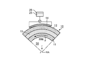
- FIGS. 1A and 1B are views showing a rolling bearing 10 with a heat generation measurement function according to a first embodiment of the present invention.
- FIG. 1A is a partial vertical cross-sectional view of a rolling bearing 10 with a heat generation measurement function
- FIG. 1B is a partial cross-sectional view of the rolling bearing 10 with a heat generation measurement function.
- a cylindrical coordinate system (r, ⁇ , Z) is used.
- r is a radial direction with the rotation axis RA as the origin (center), and ⁇ rotates around the rotation axis RA.
- the rotational direction (circumferential direction), and Z is the axial direction in which the rotational axis RA extends.
- the rolling bearing 10 with a heat measurement function includes an inner ring 11, an outer ring 12, balls (rolling elements) 13, a spin heat flow sensor 14, and a pair of seal portions 15.
- the outer ring 12 is fixed to a fixing member (not shown), and the inner ring 11 rotates. That is, the inner ring 11 is fixed to a rotating member (shaft) 30 that rotates in the circumferential direction with respect to the fixing member.
- the rotating member (shaft) 30 extends in the axial direction Z which is the direction of the rotation axis RA.
- a plurality of balls (rolling elements) 13 are disposed between the inner ring 11 and the outer ring 12.
- the pair of seal portions 15 is made of a synthetic rubber material or the like.
- the pair of seal portions 15 is disposed between the inner ring 11 and the outer ring 12 on the outer peripheral side of the ball (rolling element) 13 and each has an annular shape.
- One side (the outer peripheral end side) of each seal portion 15 is fixed to the outer ring 12, and the other side (the inner peripheral end side) is in close contact with the inner ring 11 by elastic force.
- the spin thermal current sensor 14 is a layered device having a magnetic film having magnetization in the in-plane direction.
- the spin thermal current sensor 14 is characterized in that an electromotive force in the in-plane direction is generated in proportion to the heat flow rate flowing in the in-plane direction based on the thermomagnetic effect of converting the heat flow in the magnetic body into the spin flow. Do.
- the spin thermal sensor 14 comprises a magnetic film 14a and a conductive film 14b.
- the spin thermal current sensors 14 are arranged in such a manner that they are stacked on the surface of the outer ring 12 in the radial direction r and coated. More specifically, the magnetic film 14 a is coated on the surface of the outer ring 12. The conductive film 14b is coated on the surface of the magnetic film 14a.
- Yttrium iron garnet (Bi: YIG, BiY 2 Fe 5 O 12, etc.) doped with a rare earth element such as yttrium iron garnet (YIG, Y 3 Fe 5 O 12 ) or Bi as the magnetic film 14 a Oxide magnetic materials such as CoFe 2 O 4 ) and magnetite (Fe 3 O 4 ) can be used.
- a conductive material having a large spin-orbit interaction such as a metal material such as Pt or W, or a conductive oxide material such as FePt, CoPt, NiPt, FeW, CoW, NiW alloy, or RuO 2 as the conductive film 14b. It is desirable to use
- the magnetic film 14a can be formed by a coating method such as an organic metal decomposition method (MOD method), a ferrite plating method, sputtering, liquid phase epitaxy (LPE), chemical vapor deposition (CVD) or the like.
- the conductive film 14 b can be formed by sputtering, pulsed laser deposition (PLD), electron beam evaporation, plating, or the like.
- control circuit 25 and the transmission / reception device 26 are provided outside the bearing 10, and can communicate with the outside wirelessly.
- the operation mode of the control circuit 25 can be wirelessly set from the outside. Therefore, the combination of the control circuit 25 and the transmission / reception device 26 is connected to the spin heat flow sensor 14 and acts as a communication means for wirelessly communicating with the outside.
- the heat flow measurement result data of the observed voltage V
- the control circuit 25 regards the occurrence of an abnormality and immediately transmits a radio signal via the transmission / reception device 26 to transmit the abnormality to the administrator.
- the control circuit 25, the transmission / reception device 26, and the operation method are the same as in the following embodiments.
- a magnetic conductive film having both magnetism and conductivity may be used instead of the configuration of the magnetic film 14 a and the conductive film 14 b. Also in the case of using this magnetic conductive film, an electromotive force is similarly generated by the anomalous Nernst effect (one of the thermomagnetic effects of converting the heat flow into a spin-polarized current) due to the heat flow flowing into the magnetic conductive film. By measuring the output voltage signal across the magnetic conductive film, it is possible to detect the heat generated in the bearing 10.
- FePt, CoPt, NiPt, FeW, CoW, NiW alloy or the like can be used besides Fe, Ni, Co.
- communication with the outside is performed wirelessly using the communication means, but in the present invention, communication does not have to be performed wirelessly. Because the spin heat flow sensor 14 is disposed on the fixed side (in this example, the surface of the outer ring 12), it is possible to communicate with the outside from the spin heat flow sensor 14 via a wire.
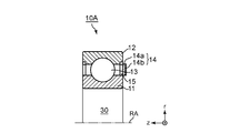
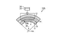
- FIG. 2A and FIG. 2B are views showing a rolling bearing with heat measurement function 10A according to a modification of the present embodiment.
- FIG. 2A is a partial vertical cross-sectional view of the rolling bearing 10A with a heat generation measurement function
- FIG. 2B is a partial cross-sectional view of the rolling bearing 10A with a heat generation measurement function.
- FIGS. 2A and 2B a cylindrical coordinate system (r, ⁇ , Z) is used as in FIGS. 1A and 1B.
- the bearing 10A of FIGS. 2A and 2B is different in that the spin heat flow sensor 14 is attached to the surface of the seal portion 15 instead of the surface of the outer ring 12.
- the magnetic film 14 a and the conductive film 14 b are stacked and coated in the axial direction Z on the surface of the seal portion 15 by using a ferrite plating method or the like.
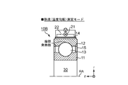
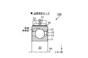
- FIGS. 3A and 3B are views showing a rolling bearing 10B having a function of measuring the temperature inside of a bearing according to a second embodiment of the present invention.
- FIG. 3A is a partial vertical cross-sectional view showing the state of the rolling bearing with temperature measurement function 10B in the heat flow (temperature gradient) measurement mode
- FIG. 3B is a rolling bearing with temperature measurement function in the temperature measurement mode. It is a fragmentary longitudinal cross-sectional view which shows the state of 10B.
- FIGS. 3A and 3B a cylindrical coordinate system (r, ⁇ , Z) is used as in FIGS. 1A and 1B.
- temperature measurement is performed in addition to heat flow by utilizing the conductive film 14b as a resistance thermometer.
- the heat flow temperature gradient
- the temperature of the friction heating portion inside the bearing can be more accurately evaluated.
- the basic configuration is the same as that of the rolling bearing 10 with a heat generation measuring device according to the first embodiment shown in FIGS. 1A and 1B, but a DC current source 21 and a switch 22 are newly introduced in this bearing 10B. It is done.
- the direct current source 21 and the switch 22 are connected in series to the spin thermal current sensor 14.
- the heat flow rate generated by frictional heat generation of the bearing 10B is determined between the two ends of the conductive film 14b constituting the spin thermal current sensor 14. Measured through the output voltage (heat flow measurement mode).
- the absolute temperature of the surface of the outer ring 12 and the heat flow rate (proportional to the temperature gradient) flowing there can be evaluated by the rolling bearing 10B with a bearing internal temperature measurement function shown in FIGS. 3A and 3B. .
- FIG. 4 is a diagram for explaining a method of estimating the internal temperature from the two parameters.
- the horizontal axis indicates the position inside the bearing, and the vertical axis indicates the temperature.
- FIG. 4 shows that the internal temperature in the frictional heating portion can be estimated from the outer ring surface temperature and the temperature gradient.
- the second embodiment it is possible to evaluate the temperature of the friction heating portion (the contact portion between the outer ring 12 and the ball 13) inside the bearing.
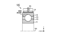
- FIG. 5A and 5B are diagrams for explaining another sensing method of the second embodiment.
- FIG. 5A is a partial longitudinal cross-sectional view showing a rolling bearing 10C with a bearing internal temperature measurement function
- FIG. 5B is a waveform diagram showing fluctuations in output voltage.
- the switch 22 is eliminated by using an alternating current source 23 instead of using the direct current source 21 of FIG.
- the output voltage V is a sum of a DC voltage component proportional to the heat flow (temperature gradient) and an AC current component depending on the resistance determined from the absolute temperature. It is generated. From this fact, it is possible to simultaneously perform heat flow (temperature gradient) measurement and absolute temperature measurement by separately evaluating them.
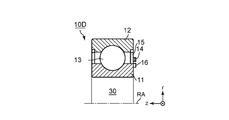
- FIG. 6A and 6B are views showing a rolling bearing 10D having a rotation speed and heat generation measurement function according to a third embodiment of the present invention.
- FIG. 6A is a partial longitudinal cross-sectional view of a rolling bearing 10D having a rotational speed and heat generation measurement function
- FIG. 6B is a partial cross-sectional view of a rolling bearing 10D having a rotational speed and heat generation measurement function.
- the cylindrical coordinate system (r, ⁇ , Z) is used in FIGS. 6A and 6B as in FIGS. 1A and 1B.
- a plurality of permanent magnets having different magnetic poles alternately are disposed along the rotational direction ⁇ , and the magnetic field emitted by them Invert the magnetization of the body film.
- the rotation information of the axis is acquired.
- the magnetic encoder 16 is fixed to the inner ring 11 side.
- the magnetic encoder 16 has a structure in which permanent magnets in which the magnetic poles (N and S poles) are alternately arranged along the rotational direction ⁇ .
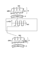
- FIG. 7 is a view for explaining the operation principle of the rolling bearing 10D having the rotation speed and heat generation measurement function shown in FIGS. 6A and 6B.
- the magnetization direction of the spin thermal sensor 14 is reversed at each rotation due to the magnetic field emitted from the permanent magnet of the magnetic encoder 16 with the relative rotational movement between the inner ring 11 and the outer ring 12. Do. From this, as a result, the output voltage V is also sign-inverted (FIG. 7). Therefore, in the third embodiment, it is possible to estimate the rotational frequency of the rotational movement from the frequency of the output voltage V.
- the frequency can be measured only by arranging one spin heat flow sensor 14.
- two spin heat flow sensors at appropriate positions (for example, positions separated by 90 degrees in the rotational angle direction ⁇ ), not only the rotational frequency but also the direction of rotation and between the inner ring and outer ring at a certain time
- the relative position (rotational angle) can also be evaluated.
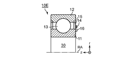
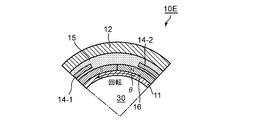
- FIGS. 8A and 8B are views showing a rolling bearing 10E having a rotational speed / heat generation measuring function when using a plurality of heat flow sensors according to a modification of the third embodiment.
- FIG. 8A is a partial longitudinal cross-sectional view of a rolling bearing 10E having a rotational speed and heat generation measurement function
- FIG. 8B is a partial cross-sectional view of a rolling bearing 10E having a rotational speed and heat generation measurement function.
- FIGS. 8A and 8B the cylindrical coordinate system (r, ⁇ , Z) is used as in FIGS. 1A and 1B.
- the first spin heat flow sensor 14 is disposed on the surface of the seal portion 15 at a position 90 degrees apart from each other in the rotational direction ⁇ on the surface of the seal portion 15. And a second spin heat flow sensor 14-2.
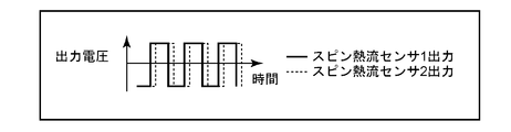
- FIG. 9 is a waveform diagram showing the output of the first spin thermal current sensor 14-1 and the output of the second spin thermal current sensor 14-2.
- the output of the first spin thermal current sensor 14-1 is indicated by a solid line "spin thermal current sensor 1 output”
- the output of the second spin thermal current sensor 14-2 is indicated by a dotted line “spin thermal current sensor 2 output”. It shows.
- the outputs of the plurality of sensors 14-1 and 14-2 are not sine waves but square waves.
- the code of sensor 1, the code of sensor 2) (+, +), (+,-), (-, +), (-,-) by identifying four ways, at which moment It is possible to see what you are doing. Also, increasing the number of sensors can increase the accuracy.
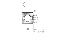
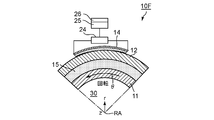
- FIGS. 10A and 10B are views showing a rolling bearing 10F with a self-supporting heat generation function according to a fourth embodiment of the present invention.
- FIG. 10A is a partial longitudinal sectional view of the self-supporting type rolling bearing with heat generation function 10F
- FIG. 10B is a partial cross-sectional view of the self-supporting type rolling bearing with heat generation function 10F.
- FIGS. 10A and 10B a cylindrical coordinate system (r, ⁇ , Z) is used as in FIGS. 1A and 1B.
- thermoelectromotive force as electric power is provided. That is, in the fourth embodiment, self-sustaining driving can be performed without external battery or external power supply, and sensing data can be transmitted to the outside wirelessly.
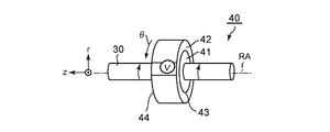
- FIGS. 11A and 11B are views showing a slide bearing 40 with a heat generation measurement function according to a modification of the present invention.
- 11A is a schematic perspective view of the slide bearing 40 with a heat generation measurement function
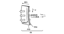
- FIG. 11B is an enlarged perspective view of a spin thermal flow sensor provided in the slide bearing 40 with a heat generation measurement function.
- a cylindrical coordinate system (r, ⁇ , Z) is used.
- r is a radial direction around the rotation axis RA
- ⁇ is a rotation direction that rotates around the rotation axis RA
- Z is the axial direction in which the rotation axis RA extends.
- the bearing 40 of this modification includes an inner ring 41, an outer ring 42, and a spin heat flow sensor 44.
- the outer ring 42 is fixed to a fixing member (not shown).
- the inner ring 41 is fixed to a shaft 30 which is a rotating member so as to rotate.
- the outer ring 42 and the inner ring 41 rotate relative to each other through the sliding surface 43.
- the combination of the inner ring 41, the outer ring 42 and the sliding surface 43 constitutes a slide bearing (41, 42, 43).
- the slide bearing 40 with a heat generation measurement function has, for example, a configuration in which a spin heat flow sensor 44 is disposed on the surface of an outer ring 42 which is an outer peripheral portion of the slide bearing (41, 42, 43). ing.
- the spin thermal current sensor 44 is composed of a magnetic film 44a and a metal film 44b, and these are arranged in the radial direction r on the surface of the outer ring 42 and coated.
- the magnetic film 44 a has magnetization in the in-plane direction (direction parallel to the axial direction Z).
- the spin thermal current sensor 44 generates an electromotive force in the in-plane direction (rotational direction ⁇ ) in proportion to the heat flow amount flowing in the surface orthogonal direction (radial direction r). By measuring the electromotive force generated in this way as the output voltage V across the metal film 44b, it is possible to detect the heat generation occurring in the slide bearings (41, 42, 43).
- the bearing includes a rolling bearing including a plurality of rolling elements disposed between the outer ring and the inner ring, and a seal portion fixed to the outer ring and sealing the plurality of rolling elements.
- the bearing with a measurement function according to appendix 1, wherein the heat flow sensor is coated on the surface of the seal portion.
- Appendix 9 The bearing with a measurement function according to Appendix 4, wherein the heat flow sensor is formed of a magnetic conductive film having both magnetism and conductivity which exhibit anomalous Nernst effect as the thermomagnetic effect.
Landscapes
- Engineering & Computer Science (AREA)
- General Engineering & Computer Science (AREA)
- Mechanical Engineering (AREA)
- Physics & Mathematics (AREA)
- General Physics & Mathematics (AREA)
- Rolling Contact Bearings (AREA)
Abstract
軸受(10)における発熱の情報を、簡潔に把握する。軸受(10)は、固定部材に固定された外輪(12)と、この外輪(12)の内側に設けられて、固定部材に対して円周方向に回転する軸に固定された内輪(11)と、を含む。熱流センサ(14)は、外輪(12)を含む固定側の表面にコーティングされて、軸の回転に伴って生じる摩擦熱の情報を含む熱起電力を生成する。
Description
本発明は、計測機能付き軸受に関する。
軸受(ベアリング)は、風力発電や車両など、回転運動する機械システムに用いられる要素部材であり、回転運動時の摩擦を減らして高効率な機械運動を実現する上で極めて重要な役割を果たす。同時に、仮に軸受の性能劣化や破損が生じた場合、機械システムの駆動にも大きな悪影響をもたらす。このため、最近では軸受の異常発見や予防保全のために、軸受に様々なセンサを取り付けて、状態を監視する取り組みが広がっている。
このうち、軸受の発熱計測は予防保全に極めて重要である。軸受での摩擦による発熱をリアルタイムで計測できれば、グリスの投入量制御や軸受の異常・性能劣化検知が可能となり、事業者にとって大きなメリットとなる。実際、熱電対型の温度センサを備えた軸受(特許文献1)や、回転センサを備えた軸受(特許文献2、特許文献3)などが報告されている。
しかしながら、このような周知の軸受における発熱や回転数の検知技術には、以下の3つの課題がある。
第一に、温度センサで本当に計測したいのは軸と軸受(または玉と保持輪)の接触部である。しかしながら、接触部に直接センサを取り付けることはできないため、摩擦部分の正確な温度を計測することはできない。
第二に、温度センサの信号は外部温度や周囲の熱容量に依存する。このため、軸受部での発熱量をリアルタイムで計測することはできない。
そして第三に、取り付けた温度センサが熱流を阻害したり機械的なバランスを崩したりして、軸受自体の性能に悪影響をもたらす可能性がある。
本発明の目的は、上述した課題のいずれかを解決する、計測機能付き軸受を提供することにある。
本発明の一実施の形態に係る計測機能付き軸受は、固定部材に固定された外輪と、該外輪の内側に設けられて、前記固定部材に対して円周方向に回転する軸に固定された内輪と、を含む軸受を備え、前記外輪を含む固定側の表面にコーティングされて、前記軸の回転に伴って生じる摩擦熱の情報を含む熱起電力を生成する熱流センサを備える。
本発明によれば、軸受における発熱の情報を簡潔に把握することができる。
以下、本発明の実施形態について説明する。
本発明の実施形態に係る計測機能付き軸受は、軸受外部にスピンゼーベック熱電素子をコーティングし、軸の回転に伴って生じる摩擦熱の情報を熱起電力(電圧)信号によってモニタリングすることを特徴とする。
本発明の第一の実施形態に係る計測機能付き軸受は、軸受外部に熱流センサをコーティングした構造を有している。軸受部の摩擦発熱によって生じる熱流を、熱流センサによって膜面方向の起電力(電圧)信号に変換して計測する。熱流センサは、例えば、磁性膜と金属膜との積層構造から成る。
本発明の第二の実施形態に係る計測機能付き軸受は、上記金属膜を抵抗温度計として活用することで、熱流に加えて温度計測をも行う。熱流(温度勾配)と温度とを同時に把握することで、軸受外部にコーティングした熱流センサから、軸受内部の摩擦発熱部の温度をより正確に把握することができる。
本発明の第三の実施形態に係る計測機能付き軸受は、回転する軸の側に、磁化方向が異なる永久磁石を回転方向に沿って交互に配置した磁気エンコーダを配置する。磁気エンコーダが発する磁場で、熱流センサを構成する磁性膜を磁化反転させる。これにより、発熱情報に加えて、軸の回転数の情報をも取得する。
図1Aおよび図1Bは、本発明の第一の実施例に係る発熱計測機能付き転がり軸受10を示す図である。図1Aは発熱計測機能付き転がり軸受10の部分縦断面図であり、図1Bは発熱計測機能付き転がり軸受10の部分横断面図である。
ここでは、図1Aおよび図1Bに示されるように、円柱座標系(r、θ、Z)を使用している。図1Aおよび図1Bに示した状態では、円柱座標系(r、θ、Z)において、rは回転軸RAを原点(中心)とした半径方向であり、θは回転軸RAを中心として回転する回転方向(円周方向)であり、Zは回転軸RAが延在する軸方向である。
本実施例の発熱計測機能付き転がり軸受10は、内輪11、外輪12、玉(転動体)13、スピン熱流センサ14、および一対のシール部15とからなる。
本実施例では外輪12は固定部材(図示せず)に固定されており、内輪11が回転する仕組みとなっている。すなわち、内輪11は、固定部材に対して円周方向に回転する回転部材(軸)30に固定されている。回転部材(軸)30は、回転軸RAの方向である軸方向Zに延在する。
玉(転動体)13は、内輪11と外輪12との間に複数個配置される。
一対のシール部15は合成ゴム材料などからなる。一対のシール部15は、玉(転動体)13の外周側で内輪11と外輪12との間に配置されて、各々が環状をしている。各シール部15の片側(外周端側)は外輪12に固定され、もう片側(内周端側)は弾性力で内輪11に押し付けられるように密着されている。このような構造を採用することで、一対のシール部15は軸受内部を密封している。
スピン熱流センサ14は、面内方向の磁化を有する磁性膜を有する層状デバイスである。スピン熱流センサ14は、磁性体における熱の流れをスピンの流れに変換する熱磁気効果に基づき、面直方向に流れる熱流量に比例して、面内方向の起電力を生成することを特徴とする。
図1Aおよび図1Bに示す実施例では、スピン熱流センサ14は磁性体膜14aと導電膜14bとからなる。スピン熱流センサ14は、これらが外輪12の表面に半径方向rに積層されてコーティングされた配置となっている。詳述すると、磁性体膜14aは外輪12の表面にコーティングされている。導電膜14bは磁性体膜14aの表面にコーティングされている。
ここで、軸受内部(具体的には玉13と外輪12、および玉13と内輪11との間)の摩擦に起因して発熱が生じると、熱流が外輪12を通してスピン熱流センサ14へと流れる。この熱流から誘起されるスピンゼーベック効果(熱流をスピン流に変換する熱磁気効果の一つ)によって磁性体膜14aにおいてスピン流が生じる。このスピン流が導電膜14bに到達すると、導電膜14bにおける逆スピンホール効果(スピン流を電流へと変換する効果)によって起電力へと変換される。こうして生じる起電力を導電膜14bの両端間の出力電圧Vとして計測することで、軸受10において生じる発熱を検知することができる。
上記磁性体膜14aとしては、イットリウム鉄ガーネット(YIG, Y3Fe5O12)やBi等の希土類元素をドープしたイットリウム鉄ガーネット(Bi:YIG, BiY2Fe5O12等)、Coフェライト(CoFe2O4)、マグネタイト(Fe3O4)などの酸化物磁性材料を用いることできる。また、導電膜14bとしてはPtやW等の金属材料や、FePt、CoPt、NiPt、FeW、CoW、NiW合金、もしくはRuO2等の導電性酸化物材料など、スピン軌道相互作用が大きい導電性材料を用いることが望ましい。
磁性体膜14aは、有機金属分解法(MOD法)等の塗布法やフェライトめっき法、スパッタ、液相エピタキシー法(LPE)、化学気相堆積法(CVD)等で形成することができる。また、導電膜14bは、スパッタ法、パルスレーザ堆積法(PLD法)、電子ビーム蒸着法、めっき法等で形成することができる。
さらに軸受10の外部には制御回路25および送受信装置26が備えられており、無線で外部との通信が可能となっている。制御回路25の動作モードは外部から無線で設定できるようになっている。したがって、制御回路25と送受信装置26との組み合わせは、スピン熱流センサ14に接続されて、無線で外部との通信を行う通信手段として働く。
次に、通信手段の動作モードの一例について説明する。平時は熱流測定の結果(観測した電圧Vのデータ)を制御回路25内に一時的に保存して、送受信装置26はその保存したデータを5分おきに外部に送信する。一方、熱流(出力電圧)が一定の閾値を超えた場合には、制御回路25は異常発生とみなして、送受信装置26を介して即座に無線を飛ばして異常を管理者に伝える。なお、これら制御回路25と送受信装置26、および動作方法については、以後の実施例でも同様のものを用いるものとする。
なお、上記スピン熱流センサとしては、磁性体膜14aと導電膜14bとからなる構成の代わりに、磁性と導電性とを兼ね備えた磁性導電膜を用いてもよい。この磁性導電膜を用いる場合も、上記熱流が磁性導電膜に流れ込むことによる異常ネルンスト効果(熱流をスピン偏極電流に変換する熱磁気効果の一つ)によって、同様に起電力が生じる。この磁性導電膜の両端間の出力電圧信号を計測することで、軸受10において生じる発熱を検知することができる。
磁性導電膜の材料としては、Fe、Ni、Coのほか、FePt、CoPt、NiPt、FeW、CoW、NiW合金等を用いることができる。
本第一の実施例によれば、出力電圧Vを計測することで、軸受内部の摩擦発熱をモニタリングできるという効果がある。
尚、第一の実施例では、通信手段を使用して無線で外部と通信を行っているが、本発明では通信を必ずしも無線で行う必要はない。何故なら、スピン熱流センサ14を固定側(本例では、外輪12の表面)に配置しているので、スピン熱流センサ14から有線を介して外部と通信することが可能だからである。
図2Aおよび図2Bは、本実施例の変形例に係る熱計測機能付き転がり軸受10Aを示す図である。図2Aは発熱計測機能付き転がり軸受10Aの部分縦断面図であり、図2Bは発熱計測機能付き転がり軸受10Aの部分横断面図である。
図2Aおよび図2Bにおいても、図1Aおよび図1Bと同様に、円柱座標系(r、θ、Z)を使用している。
構成要素は図1Aおよび図1Bの軸受10と同じだが、図2Aおよび図2Bの軸受10Aではスピン熱流センサ14を外輪12の表面ではなく、シール部15の表面に取り付けている点が異なる。
本変形例では、フェライトめっき法などを用いることで、磁性体膜14aと導電膜14bをシール部15の表面上に軸方向Zに積層してコーティングしている。
本変形例でも、出力電圧Vを計測することで、軸受内部の摩擦発熱をモニタリングできるという効果がある。
図3Aおよび図3Bは、本発明の第二の実施例に係る軸受内部温度計測機能付き転がり軸受10Bを示す図である。図3Aは熱流(温度勾配)測定モード時での軸受内部温度計測機能付き転がり軸受10Bの状態を示す部分縦断面図であり、図3Bは温度測定モード時での軸受内部温度計測機能付き転がり軸受10Bの状態を示す部分縦断面図である。
図3Aおよび図3Bにおいても、図1Aおよび図1Bと同様に、円柱座標系(r、θ、Z)を使用している。
本発明の第二の実施例では、前記導電膜14bを抵抗温度計として活用することで、熱流に加えて温度計測も行う。熱流(温度勾配)と温度を同時に把握することで、軸受内部の摩擦発熱部の温度をより正確に評価することができる。
基本構成は図1Aおよび図1Bに示す第一の実施例の発熱計測装置付き転がり軸受10と同じだが、この軸受内部温度計測機能付き転がり軸受10Bでは新たに直流電流源21とスイッチ22とが導入されている。
直流電流源21とスイッチ22とは、スピン熱流センサ14に直列に接続されている。
図3Aに示されるように、スイッチ22がOFFの場合は第一の実施例と同様に、軸受10Bの摩擦発熱によって生じた熱流量を、スピン熱流センサ14を構成する導電膜14bの両端間の出力電圧を通して計測する(熱流測定モード)。
一方、図3Bに示されるように、スイッチ22がONの状態になると、直流電流源21からスピン熱流センサ14の導電膜14bに一定電流が流れ込むことから、前記出力電圧Vが変化する。この変化分は、前記一定電流と導電膜14bの抵抗との積に比例する。このことから、この変化分を観測することで導電膜14bの抵抗変化を評価することができる。多くの導電性材料では、抵抗率は温度に単調に依存することから、これによって導電膜14bの部分の温度を計測することができる(温度測定モード)。
この熱流測定モードと温度測定モードとを交互に繰り返せば、摩擦発熱部の温度のより正確な評価が可能となる。
一般的に、軸受では、主に外輪12と玉13の摩擦部などで発熱が生じるが、この箇所に温度センサを直接取り付けることは機械設計上難しい。このことから、一般的な通常知られている方法では、摩擦発熱部の温度を直接評価することはできない。
これに対して、図3Aおよび図3Bに示す軸受内部温度計測機能付き転がり軸受10Bによって、外輪12の表面の絶対温度とそこで流れている熱流量(温度勾配に比例)とを評価することができる。
図4は、その2つのパラメータから内部温度を推定する方法を説明するための図である。図4において、横軸は軸受内部位置を示し、縦軸は温度を示す。図4は、外輪表面温度と温度勾配とから摩擦発熱部での内部温度を推定できることを示している。
このように、第二の実施例によれば、軸受内部の摩擦発熱部(外輪12と玉13との接触部)の温度を評価することが可能となるという効果を奏する。
図5Aおよび図5Bは、第二の実施例の別のセンシング方式を説明するための図である。図5Aは軸受内部温度計測機能付き転がり軸受10Cを示す部分縦断面図であり、図5Bは出力電圧の変動を示す波形図である。
本方式では、図5Aに示されるように、図3の直流電流源21を用いる代わりに交流電流源23を用いて、スイッチ22を削除している。
このような構成を採用すれば、図5Bに示されるように、出力電圧Vは、熱流(温度勾配)に比例する直流電圧成分と、絶対温度から決まる抵抗に依存する交流電流成分との和として生成される。このことから、これらを分離して評価することで、熱流(温度勾配)計測と絶対温度計測とを同時に行うことができる。
図5Aおよび図5Bに示した別のセンシング方式によれば、上記第二の実施例の効果に加えて、図3Aおよび図3Bに示す軸受内部温度計測機能付き転がり軸受10Bで測定モードを切り替えるために必要だったスイッチ22が不要となり、素子構成が簡素化されるという効果をも奏する。
図6Aおよび図6Bは、本発明の第三の実施例に係る回転数・発熱計測機能付き転がり軸受10Dを示す図である。図6Aは回転数・発熱計測機能付き転がり軸受10Dの部分縦断面図であり、図6Bは回転数・発熱計測機能付き転がり軸受10Dの部分横断面図である。
図6Aおよび図6Bにおいても、図1Aおよび図1Bと同様に、円柱座標系(r、θ、Z)を使用している。
本発明の第三の実施例では、軸受10Dの内輪11側に、磁極が交互に異なる複数の永久磁石を回転方向θに沿って配置し、それが発する磁場で軸受側のスピンゼーベック素子の磁性体膜を磁化反転させる。これにより、第三の実施例では、発熱情報に加えて軸の回転情報も取得する。
図6Aおよび図6Bに示す回転数・発熱計測機能付き転がり軸受10Dでは図2Aおよび図2Bで示した軸受10Aと同様の構成に加えて、内輪11側に磁気エンコーダ16が固定されている。磁気エンコーダ16は、回転方向θに沿って磁極(N極、S極)が互い違いになった永久磁石が配置された構造を有している。
図7は、図6Aおよび図6Bに示した回転数・発熱計測機能付き転がり軸受10Dの動作原理を説明するための図である。
このような構成をとれば、内輪11と外輪12との間の相対的な回転運動に伴い、磁気エンコーダ16の永久磁石からの発せられる磁場によってスピン熱流センサ14の磁化方向が回転の度に反転する。このことから、結果としてその出力電圧Vも符号反転する(図7)。したがって、第三の実施例では、出力電圧Vの周波数から回転運動の回転周波数を評価することが可能となる。
このように、第三の実施例によれば、発熱情報に加えて軸30の回転数の情報も取得することができるという効果を奏する。
上記第三の実施例では、スピン熱流センサ14を1個配置するだけで周波数の計測を可能としている。一方、スピン熱流センサを適切な位置(例えば回転角方向θに90度離れた位置)に2個配置することで、回転周波数だけでなく、回転の方向、およびある時間における内輪と外輪の間の相対位置(回転角度)も評価することができる。
図8Aおよび図8Bは、第三の実施例の変形例に係る、複数の熱流センサを用いた場合の回転数・発熱計測機能付き転がり軸受10Eを示す図である。図8Aは回転数・発熱計測機能付き転がり軸受10Eの部分縦断面図であり、図8Bは回転数・発熱計測機能付き転がり軸受10Eの部分横断面図である。
図8Aおよび図8Bにおいても、図1Aおよび図1Bと同様に、円柱座標系(r、θ、Z)を使用している。
図8Bに示されるように、回転数・発熱計測機能付き転がり軸受10Eは、シール部15の表面上に、互いに回転方向θに90度離れた位置に配置された、第1のスピン熱流センサ14-1と第2のスピン熱流センサ14-2とを有する。
図9は、第1のスピン熱流センサ14-1の出力と第2のスピン熱流センサ14-2の出力とを示す波形図である。図9では、第1のスピン熱流センサ14-1の出力を実線で「スピン熱流センサ1出力」で示し、第2のスピン熱流センサ14-2の出力を点線で「スピン熱流センサ2出力」で示している。
図9から明らかなように、複数のセンサ14-1、14-2の相対出力を見ることで、ある瞬間における回転の角度(位置)をより細かく検知することができる。
本変形例では、図9から分かるように、複数のセンサ14-1、14-2の出力は、正弦波ではなく矩形波になる。(センサ1の符号,センサ2の符号)=(+,+)、(+,-)、(-,+)、(-,-)の4通りを見分けることによって、その瞬間にどのエリアに位置しているかを見ることが可能となる。また、センサの数を増やすとより精度を高めることができる。
図8Aおよび図8Bに示した変形例によれば、上記第三の実施例の効果に加えて、回転の方向や相対位置(回転角度)をも検出できるという効果をも奏する。
図10Aおよび図10Bは、本発明の第四の実施例に係る自立駆動型発熱計測機能付き転がり軸受10Fを示す図である。図10Aは自立駆動型発熱計測機能付き転がり軸受10Fの部分縦断面図であり、図10Bは自立駆動型発熱計測機能付き転がり軸受10Fの部分横断面図である。
図10Aおよび図10Bにおいても、図1Aおよび図1Bと同様に、円柱座標系(r、θ、Z)を使用している。
第四の実施例では、図1Aおよび図1Bに示した第一の実施例の発熱計測機能付き転がり軸受10の上記構成に加えて、熱起電力を電力として蓄積するキャパシタ24を備える。すなわち、第四の実施例では、外部電池や外部からの給電無しに自立駆動し、センシングデータを無線で外部に送信することができる。
このように、第四の実施例によれば、外部からの給電無しに、センシングデータを無線で外部に送信できるという効果を奏する。
なお、上記の実施例では、様々な種類のある軸受の中でも、転がり軸受、特に玉軸受についての実装方法を記述したが、本発明は、他の軸受方式(滑り軸受やころ軸受)についても同様の実装が可能となる。
[変形例]
図11Aおよび図11Bは、本発明の変形例に係る発熱計測機能付き滑り軸受40を示す図である。図11Aは発熱計測機能付き滑り軸受40の概略斜視図であり、図11Bは発熱計測機能付き滑り軸受40に設けられるスピン熱流センサを拡大して示す斜視図である。
図11Aおよび図11Bは、本発明の変形例に係る発熱計測機能付き滑り軸受40を示す図である。図11Aは発熱計測機能付き滑り軸受40の概略斜視図であり、図11Bは発熱計測機能付き滑り軸受40に設けられるスピン熱流センサを拡大して示す斜視図である。
ここでは、図11Aおよび図11Bに示されるように、円柱座標系(r、θ、Z)を使用している。図11Aおよび図11Bに示した状態では、円柱座標系(r、θ、Z)において、rは回転軸RAを中心とした半径方向であり、θは回転軸RAの回りに回転する回転方向であり、Zは回転軸RAが延在する軸方向である。
本変形例の軸受40は、内輪41と、外輪42と、スピン熱流センサ44とから成る。外輪42は、固定部材(図示せず)に固定されている。内輪41は回転部材である軸30に固定されて、回転するようになっている。外輪42と内輪41とは滑り面43を介して相対回転するようになっている。
すなわち、内輪41と外輪42と滑り面43との組み合わせによって、滑り軸受(41,42,43)が構成されている。
図11Aに示されるように、発熱計測機能付き滑り軸受40は、その一例として、滑り軸受(41,42,43)の外周部である外輪42の表面にスピン熱流センサ44を配置した構成をしている。
図11Bに示されるように、スピン熱流センサ44は磁性膜44aと金属膜44bとからなり、これらを外輪42の表面上に半径方向rに積層してコーティングされた配置となっている。磁性膜44aは、面内方向(軸方向Zと平行な方向)に磁化を有する。スピン熱流センサ44は、面直方向(半径方向r)に流れる熱流量に比例して、面内方向(回転方向θ)の起電力を生成する。こうして生じる起電力を金属膜44bの両端間の出力電圧Vとして計測することで、滑り軸受(41,42,43)において生じる発熱を検知することができる。
このように、変形例によれば、出力電圧Vを計測することで、滑り軸受(41,42,43)の内部の摩擦発熱をモニタリングできるという効果がある。
以上、実施形態および実施例などを参照して本発明を説明したが、本発明は上記実施形態や実施例などに限定されるものではない。本発明の構成や詳細には、本発明のスコープ内で当業者が理解しえる様々な変更をすることができる。
上記の実施形態の一部又は全部は、以下の付記のようにも記載されうるが、以下には限られない。
(付記1)
固定部材に固定された外輪と、
該外輪の内側に設けられて、前記固定部材に対して円周方向に回転する軸に固定された内輪と、
を含む軸受を備え、
前記外輪を含む固定側の表面にコーティングされて、前記軸の回転に伴って生じる摩擦熱の情報を含む熱起電力を生成する熱流センサを備える、計測機能付き軸受。
固定部材に固定された外輪と、
該外輪の内側に設けられて、前記固定部材に対して円周方向に回転する軸に固定された内輪と、
を含む軸受を備え、
前記外輪を含む固定側の表面にコーティングされて、前記軸の回転に伴って生じる摩擦熱の情報を含む熱起電力を生成する熱流センサを備える、計測機能付き軸受。
(付記2)
前記熱流センサは、前記外輪の表面上にコーティングされている、付記1に記載の計測機能付き軸受。
前記熱流センサは、前記外輪の表面上にコーティングされている、付記1に記載の計測機能付き軸受。
(付記3)
前記軸受は、前記外輪と前記内輪との間に配置された複数の転動体と、前記外輪に固定されて前記複数の転動体を密封するシール部とを備えた、転がり軸受からなり、
前記熱流センサは、前記シール部の表面上にコーティングされている、付記1に記載の計測機能付き軸受。
前記軸受は、前記外輪と前記内輪との間に配置された複数の転動体と、前記外輪に固定されて前記複数の転動体を密封するシール部とを備えた、転がり軸受からなり、
前記熱流センサは、前記シール部の表面上にコーティングされている、付記1に記載の計測機能付き軸受。
(付記4)
前記熱流センサは、熱磁気効果を発現する少なくとも一層の膜から成る、付記1乃至3のいずれか1つに記載の計測機能付き軸受。
前記熱流センサは、熱磁気効果を発現する少なくとも一層の膜から成る、付記1乃至3のいずれか1つに記載の計測機能付き軸受。
(付記5)
前記熱流センサは、前記熱磁気効果としてスピンゼーベック効果を発現する磁性体膜と導電膜とから成る、付記4に記載の計測機能付き軸受。
前記熱流センサは、前記熱磁気効果としてスピンゼーベック効果を発現する磁性体膜と導電膜とから成る、付記4に記載の計測機能付き軸受。
(付記6)
熱流計測と温度計測とを可能にする計測制御手段を更に有する、付記5に記載の計測機能付き軸受。
熱流計測と温度計測とを可能にする計測制御手段を更に有する、付記5に記載の計測機能付き軸受。
(付記7)
前記計測制御手段は、前記熱流センサに直列に接続された、直流電流源とスイッチとから成る、付記6に記載の計測機能付き軸受。
前記計測制御手段は、前記熱流センサに直列に接続された、直流電流源とスイッチとから成る、付記6に記載の計測機能付き軸受。
(付記8)
前記計測制御手段は、前記熱流センサに接続された交流電流源から成る、付記6に記載の計測機能付き軸受。
前記計測制御手段は、前記熱流センサに接続された交流電流源から成る、付記6に記載の計測機能付き軸受。
(付記9)
前記熱流センサは、前記熱磁気効果として異常ネルンスト効果を発現する磁性と導電性とを兼ね備えた磁性導電膜から成る、付記4に記載の計測機能付き軸受。
前記熱流センサは、前記熱磁気効果として異常ネルンスト効果を発現する磁性と導電性とを兼ね備えた磁性導電膜から成る、付記4に記載の計測機能付き軸受。
(付記10)
前記熱流センサと近接するように、前記内輪に取り付けられた磁気エンコーダを更に有する、付記3に記載の計測機能付き軸受。
前記熱流センサと近接するように、前記内輪に取り付けられた磁気エンコーダを更に有する、付記3に記載の計測機能付き軸受。
(付記11)
前記熱流センサが、前記シール部の表面上に、離間して複数個配置されている、付記3に記載の計測機能付き軸受。
前記熱流センサが、前記シール部の表面上に、離間して複数個配置されている、付記3に記載の計測機能付き軸受。
(付記12)
前記熱流センサに接続されて、無線で外部との通信を行う通信手段を更に備える、付記1乃至11のいずれか1つに記載の計測機能付き軸受。
前記熱流センサに接続されて、無線で外部との通信を行う通信手段を更に備える、付記1乃至11のいずれか1つに記載の計測機能付き軸受。
(付記13)
前記熱起電力を電力として蓄積するキャパシタを更に含む、付記12に記載の計測機能付き軸受。
前記熱起電力を電力として蓄積するキャパシタを更に含む、付記12に記載の計測機能付き軸受。
この出願は、2017年9月11日に出願された日本出願特願2017-173877を基礎とする優先権を主張し、その開示の全てをここに取り込む。
10、10A 発熱計測機能付き転がり軸受
10B、10C 軸受内部温度計測機能付き転がり軸受
10D、10E 回転数・発熱計測機能付き転がり軸受
10F 自立駆動型発熱計測機能付き転がり軸受
11 内輪
12 外輪
13 玉(転動体)
14 スピン熱流センサ
14-1 第1のスピン熱流センサ
14-2 第2のスピン熱流センサ
14a 磁性体膜
14b 導電膜
15 シール部
16 磁気エンコーダ
21 直流電流源
22 スイッチ
23 交流電流源
24 キャパシタ
25 制御回路
26 送受信装置
30 回転部材(軸)
40 発熱計測機能付き滑り軸受
41 内輪
42 外輪
43 滑り面
44 スピン熱流センサ
44a 磁性膜
44b 金属膜
RA 回転軸
r 半径方向
θ 回転方向(円周方向)
Z 軸方向
V 出力電圧
Claims (13)
- 固定部材に固定された外輪と、
該外輪の内側に設けられて、前記固定部材に対して円周方向に回転する軸に固定された内輪と、
を含む軸受を備え、
前記外輪を含む固定側の表面にコーティングされて、前記軸の回転に伴って生じる摩擦熱の情報を含む熱起電力を生成する熱流センサを備える、計測機能付き軸受。 - 前記熱流センサは、前記外輪の表面上にコーティングされている、請求項1に記載の計測機能付き軸受。
- 前記軸受は、前記外輪と前記内輪との間に配置された複数の転動体と、前記外輪に固定されて前記複数の転動体を密封するシール部とを備えた、転がり軸受からなり、
前記熱流センサは、前記シール部の表面上にコーティングされている、請求項1に記載の計測機能付き軸受。 - 前記熱流センサは、熱磁気効果を発現する少なくとも一層の膜から成る、請求項1乃至3のいずれか1つに記載の計測機能付き軸受。
- 前記熱流センサは、前記熱磁気効果としてスピンゼーベック効果を発現する磁性体膜と導電膜とから成る、請求項4に記載の計測機能付き軸受。
- 熱流計測と温度計測とを可能にする計測制御手段を更に有する、請求項5に記載の計測機能付き軸受。
- 前記計測制御手段は、前記熱流センサに直列に接続された、直流電流源とスイッチとから成る、請求項6に記載の計測機能付き軸受。
- 前記計測制御手段は、前記熱流センサに接続された交流電流源から成る、請求項6に記載の計測機能付き軸受。
- 前記熱流センサは、前記熱磁気効果として異常ネルンスト効果を発現する磁性と導電性とを兼ね備えた磁性導電膜から成る、請求項4に記載の計測機能付き軸受。
- 前記熱流センサと近接するように、前記内輪に取り付けられた磁気エンコーダを更に有する、請求項3に記載の計測機能付き軸受。
- 前記熱流センサが、前記シール部の表面上に、離間して複数個配置されている、請求項3に記載の計測機能付き軸受。
- 前記熱流センサに接続されて、無線で外部との通信を行う通信手段を更に備える、請求項1乃至11のいずれか1つに記載の計測機能付き軸受。
- 前記熱起電力を電力として蓄積するキャパシタを更に含む、請求項12に記載の計測機能付き軸受。
Priority Applications (1)
| Application Number | Priority Date | Filing Date | Title |
|---|---|---|---|
| US16/646,016 US11105376B2 (en) | 2017-09-11 | 2018-08-03 | Bearing with measurement function |
Applications Claiming Priority (2)
| Application Number | Priority Date | Filing Date | Title |
|---|---|---|---|
| JP2017173877A JP2019049318A (ja) | 2017-09-11 | 2017-09-11 | 計測機能付き軸受 |
| JP2017-173877 | 2017-09-11 |
Publications (1)
| Publication Number | Publication Date |
|---|---|
| WO2019049575A1 true WO2019049575A1 (ja) | 2019-03-14 |
Family
ID=65633979
Family Applications (1)
| Application Number | Title | Priority Date | Filing Date |
|---|---|---|---|
| PCT/JP2018/029225 Ceased WO2019049575A1 (ja) | 2017-09-11 | 2018-08-03 | 計測機能付き軸受 |
Country Status (3)
| Country | Link |
|---|---|
| US (1) | US11105376B2 (ja) |
| JP (1) | JP2019049318A (ja) |
| WO (1) | WO2019049575A1 (ja) |
Cited By (2)
| Publication number | Priority date | Publication date | Assignee | Title |
|---|---|---|---|---|
| JP2020159393A (ja) * | 2019-03-25 | 2020-10-01 | Ntn株式会社 | 軸受装置 |
| CN113586602A (zh) * | 2021-07-23 | 2021-11-02 | 上海交通大学 | 轴承滚子自供电及滚子状态监测装置及工作方法 |
Families Citing this family (2)
| Publication number | Priority date | Publication date | Assignee | Title |
|---|---|---|---|---|
| JP6940243B1 (ja) * | 2021-04-22 | 2021-09-22 | 安藤 隆 | 軸受箱 |
| JP2024085474A (ja) * | 2022-12-15 | 2024-06-27 | 多摩川精機株式会社 | エンコーダ装置 |
Citations (6)
| Publication number | Priority date | Publication date | Assignee | Title |
|---|---|---|---|---|
| JP2003113835A (ja) * | 2001-10-05 | 2003-04-18 | Koyo Seiko Co Ltd | 転がり軸受 |
| JP2007040917A (ja) * | 2005-08-05 | 2007-02-15 | Kawaso Electric Industrial Co Ltd | 温度測定方法及びその装置 |
| JP2008223843A (ja) * | 2007-03-12 | 2008-09-25 | Nsk Ltd | 発電装置付回転支持装置 |
| JP2009174705A (ja) * | 2007-12-26 | 2009-08-06 | Jtekt Corp | センサー付き転がり軸受装置 |
| JP2013072703A (ja) * | 2011-09-27 | 2013-04-22 | Nec Corp | 温度測定装置、および温度測定方法 |
| JP2014072256A (ja) * | 2012-09-28 | 2014-04-21 | Tohoku Univ | 熱電発電デバイス |
Family Cites Families (25)
| Publication number | Priority date | Publication date | Assignee | Title |
|---|---|---|---|---|
| FR2771716B1 (fr) * | 1997-11-28 | 1999-12-31 | Roulements Soc Nouvelle | Dispositif de protection d'un codeur magnetique |
| JP4114334B2 (ja) * | 2001-10-09 | 2008-07-09 | 株式会社ジェイテクト | 転がり軸受 |
| EP1329727A1 (en) * | 2001-10-18 | 2003-07-23 | Nsk Ltd | Rotation-speed sensor device |
| JP2004003601A (ja) * | 2002-04-23 | 2004-01-08 | Nsk Ltd | センサ付転がり軸受ユニット |
| JP4639282B2 (ja) | 2005-10-26 | 2011-02-23 | 多摩川精機株式会社 | 角度センサ一体型滑り軸受 |
| JP2007286002A (ja) * | 2006-04-20 | 2007-11-01 | Nsk Ltd | 軸受装置 |
| US8237431B2 (en) * | 2007-07-05 | 2012-08-07 | Terry Fruehling | Wheel speed sensor |
| JP2012149716A (ja) * | 2011-01-20 | 2012-08-09 | Ntn Corp | センサ装備シール付き軸受 |
| FR2977667B1 (fr) | 2011-07-04 | 2014-02-07 | Ntn Snr Roulements | Module de surveillance d'au moins une grandeur physique caracteristique de l'etat d'un organe de guidage par contact |
| JP2013061030A (ja) | 2011-09-14 | 2013-04-04 | Ntn Corp | 回転センサ付軸受 |
| JP5327305B2 (ja) * | 2011-12-13 | 2013-10-30 | 日本精工株式会社 | エンコーダ付組み合わせシールリング |
| RU2542941C2 (ru) * | 2013-02-05 | 2015-02-27 | Федеральное государственное бюджетное образовательное учреждение высшего профессионального образования Самарский государственный технический университет | Способ компенсации упругих тепловых деформаций подшипников шпинделей металлообрабатывающих станков и устройство для его реализации |
| JP6215569B2 (ja) * | 2013-05-10 | 2017-10-18 | Ntn株式会社 | 転がり軸受装置 |
| JP2015094454A (ja) * | 2013-11-14 | 2015-05-18 | Ntn株式会社 | 回転センサ付き転がり軸受 |
| CN204200868U (zh) * | 2014-10-24 | 2015-03-11 | 河南通利机器制造有限公司 | 一种新型废钢破碎机主轴轴承控温装置 |
| KR20170104496A (ko) * | 2015-01-28 | 2017-09-15 | 콘티넨탈 테베스 아게 운트 코. 오하게 | 대칭적으로 매립된 센서 엘리먼트들을 갖는 센서 |
| JP2017053382A (ja) * | 2015-09-07 | 2017-03-16 | 中西金属工業株式会社 | センサホルダ部を有する保護カバー、及び前記保護カバーを備えた軸受装置、並びにセンサホルダ部を有する保護カバーの製造方法 |
| TWI585312B (zh) * | 2015-12-30 | 2017-06-01 | 上銀科技股份有限公司 | 感測器結構 |
| JP6500825B2 (ja) * | 2016-04-08 | 2019-04-17 | 株式会社デンソー | 監視装置 |
| JP6772605B2 (ja) * | 2016-07-12 | 2020-10-21 | 株式会社ジェイテクト | 吐出異常検出装置およびその検出方法 |
| FR3059852B1 (fr) * | 2016-12-01 | 2019-08-23 | IFP Energies Nouvelles | Machine electrique tournante integrant un capteur de position magnetique. |
| CN206246515U (zh) * | 2016-12-13 | 2017-06-13 | 施国荣 | 一种具有自动保护及检测功能的智能轴承 |
| CN106481656B (zh) * | 2016-12-13 | 2021-07-23 | 施国荣 | 一种具有自动保护及检测功能的智能轴承 |
| DK179778B1 (en) * | 2017-09-15 | 2019-05-28 | Envision Energy (Denmark) Aps | Improved bearing and method of operating a bearing |
| US10837510B2 (en) * | 2018-04-10 | 2020-11-17 | Bendix Spicer Foundation Brake Llc | Thermally isolated composite exciter ring |
-
2017
- 2017-09-11 JP JP2017173877A patent/JP2019049318A/ja active Pending
-
2018
- 2018-08-03 WO PCT/JP2018/029225 patent/WO2019049575A1/ja not_active Ceased
- 2018-08-03 US US16/646,016 patent/US11105376B2/en active Active
Patent Citations (6)
| Publication number | Priority date | Publication date | Assignee | Title |
|---|---|---|---|---|
| JP2003113835A (ja) * | 2001-10-05 | 2003-04-18 | Koyo Seiko Co Ltd | 転がり軸受 |
| JP2007040917A (ja) * | 2005-08-05 | 2007-02-15 | Kawaso Electric Industrial Co Ltd | 温度測定方法及びその装置 |
| JP2008223843A (ja) * | 2007-03-12 | 2008-09-25 | Nsk Ltd | 発電装置付回転支持装置 |
| JP2009174705A (ja) * | 2007-12-26 | 2009-08-06 | Jtekt Corp | センサー付き転がり軸受装置 |
| JP2013072703A (ja) * | 2011-09-27 | 2013-04-22 | Nec Corp | 温度測定装置、および温度測定方法 |
| JP2014072256A (ja) * | 2012-09-28 | 2014-04-21 | Tohoku Univ | 熱電発電デバイス |
Cited By (3)
| Publication number | Priority date | Publication date | Assignee | Title |
|---|---|---|---|---|
| JP2020159393A (ja) * | 2019-03-25 | 2020-10-01 | Ntn株式会社 | 軸受装置 |
| JP7206141B2 (ja) | 2019-03-25 | 2023-01-17 | Ntn株式会社 | 軸受装置 |
| CN113586602A (zh) * | 2021-07-23 | 2021-11-02 | 上海交通大学 | 轴承滚子自供电及滚子状态监测装置及工作方法 |
Also Published As
| Publication number | Publication date |
|---|---|
| JP2019049318A (ja) | 2019-03-28 |
| US20200263736A1 (en) | 2020-08-20 |
| US11105376B2 (en) | 2021-08-31 |
Similar Documents
| Publication | Publication Date | Title |
|---|---|---|
| CN108444628B (zh) | 磁弹性扭矩传感器 | |
| US11105376B2 (en) | Bearing with measurement function | |
| US6154025A (en) | Contactless potentiometer and device for contactlessly sensing a position of an object | |
| US4523482A (en) | Lightweight torquemeter and torque-measuring method | |
| US9350216B2 (en) | Integrated multi-turn absolute position sensor for high pole count motors | |
| JP4907770B2 (ja) | フラックスゲート・センサを使用する位置エンコーダ | |
| JP6301970B2 (ja) | 磁気リニアまたはロータリエンコーダ | |
| JP2012533058A5 (ja) | ||
| US20180172477A1 (en) | Method for operating a rotation sensor and corresponding rotation sensor | |
| BRPI1107464A2 (pt) | Disposição de sensores para o registro tanto da posição axial como também da posição de rotação de um eixo deslocável ou rotatório na direção longitudinal | |
| JP4269784B2 (ja) | センサ付軸受 | |
| JP2010539455A (ja) | 支承されたシャフトのための測定構造 | |
| JP5857470B2 (ja) | センサ付き転がり軸受装置 | |
| WO2017073280A1 (ja) | 磁気検出装置及び移動体検出装置 | |
| JP6483069B2 (ja) | キャリアを含むセンサデバイス | |
| JP2020537152A (ja) | 磁気インピーダンス効果を利用した距離及び角度を測定するための電磁計測システム | |
| EP4278154B1 (fr) | Capteur de position sans contact comportant un aimant permanent | |
| RU2436037C1 (ru) | Абсолютный датчик угла поворота | |
| US9726639B1 (en) | Apparatus for detecting magnetic flux leakage and methods of making and using same | |
| US20160146686A1 (en) | Sensor and Method for Detecting a Position of an Effective Surface of the Sensor | |
| Slatter | B3. 1-Magnetoresistive (MR) Sensors for Angle-, Path-and Current Measurement in Harsh Environments | |
| Mateev et al. | Magnetic elastomer sensor for dynamic torque measurements in magnetic gears | |
| US20250020685A1 (en) | Magnet-based detection system for detecting a movement of a movable object | |
| Garmabdari et al. | Sensory system for the electronic water meter | |
| Mateev et al. | Magnetic elastomer sensor for dynamic torque |
Legal Events
| Date | Code | Title | Description |
|---|---|---|---|
| 121 | Ep: the epo has been informed by wipo that ep was designated in this application |
Ref document number: 18855046 Country of ref document: EP Kind code of ref document: A1 |
|
| NENP | Non-entry into the national phase |
Ref country code: DE |
|
| 122 | Ep: pct application non-entry in european phase |
Ref document number: 18855046 Country of ref document: EP Kind code of ref document: A1 |