WO2019049562A1 - 物質検知装置及び物質検知方法 - Google Patents
物質検知装置及び物質検知方法 Download PDFInfo
- Publication number
- WO2019049562A1 WO2019049562A1 PCT/JP2018/028745 JP2018028745W WO2019049562A1 WO 2019049562 A1 WO2019049562 A1 WO 2019049562A1 JP 2018028745 W JP2018028745 W JP 2018028745W WO 2019049562 A1 WO2019049562 A1 WO 2019049562A1
- Authority
- WO
- WIPO (PCT)
- Prior art keywords
- gas
- detection
- substance
- visible light
- image
- Prior art date
- Legal status (The legal status is an assumption and is not a legal conclusion. Google has not performed a legal analysis and makes no representation as to the accuracy of the status listed.)
- Ceased
Links
Images


Classifications
-
- G—PHYSICS
- G01—MEASURING; TESTING
- G01J—MEASUREMENT OF INTENSITY, VELOCITY, SPECTRAL CONTENT, POLARISATION, PHASE OR PULSE CHARACTERISTICS OF INFRARED, VISIBLE OR ULTRAVIOLET LIGHT; COLORIMETRY; RADIATION PYROMETRY
- G01J3/00—Spectrometry; Spectrophotometry; Monochromators; Measuring colours
- G01J3/28—Investigating the spectrum
- G01J3/42—Absorption spectrometry; Double beam spectrometry; Flicker spectrometry; Reflection spectrometry
- G01J3/433—Modulation spectrometry; Derivative spectrometry
-
- G—PHYSICS
- G01—MEASURING; TESTING
- G01M—TESTING STATIC OR DYNAMIC BALANCE OF MACHINES OR STRUCTURES; TESTING OF STRUCTURES OR APPARATUS, NOT OTHERWISE PROVIDED FOR
- G01M3/00—Investigating fluid-tightness of structures
- G01M3/02—Investigating fluid-tightness of structures by using fluid or vacuum
- G01M3/04—Investigating fluid-tightness of structures by using fluid or vacuum by detecting the presence of fluid at the leakage point
- G01M3/20—Investigating fluid-tightness of structures by using fluid or vacuum by detecting the presence of fluid at the leakage point using special tracer materials, e.g. dye, fluorescent material, radioactive material
- G01M3/22—Investigating fluid-tightness of structures by using fluid or vacuum by detecting the presence of fluid at the leakage point using special tracer materials, e.g. dye, fluorescent material, radioactive material for pipes, cables or tubes; for pipe joints or seals; for valves; for welds; for containers, e.g. radiators
-
- G—PHYSICS
- G01—MEASURING; TESTING
- G01M—TESTING STATIC OR DYNAMIC BALANCE OF MACHINES OR STRUCTURES; TESTING OF STRUCTURES OR APPARATUS, NOT OTHERWISE PROVIDED FOR
- G01M3/00—Investigating fluid-tightness of structures
- G01M3/38—Investigating fluid-tightness of structures by using light
-
- G—PHYSICS
- G01—MEASURING; TESTING
- G01N—INVESTIGATING OR ANALYSING MATERIALS BY DETERMINING THEIR CHEMICAL OR PHYSICAL PROPERTIES
- G01N21/00—Investigating or analysing materials by the use of optical means, i.e. using sub-millimetre waves, infrared, visible or ultraviolet light
- G01N21/17—Systems in which incident light is modified in accordance with the properties of the material investigated
- G01N21/25—Colour; Spectral properties, i.e. comparison of effect of material on the light at two or more different wavelengths or wavelength bands
- G01N21/31—Investigating relative effect of material at wavelengths characteristic of specific elements or molecules, e.g. atomic absorption spectrometry
- G01N21/35—Investigating relative effect of material at wavelengths characteristic of specific elements or molecules, e.g. atomic absorption spectrometry using infrared light
- G01N21/3504—Investigating relative effect of material at wavelengths characteristic of specific elements or molecules, e.g. atomic absorption spectrometry using infrared light for analysing gases, e.g. multi-gas analysis
-
- G—PHYSICS
- G01—MEASURING; TESTING
- G01N—INVESTIGATING OR ANALYSING MATERIALS BY DETERMINING THEIR CHEMICAL OR PHYSICAL PROPERTIES
- G01N21/00—Investigating or analysing materials by the use of optical means, i.e. using sub-millimetre waves, infrared, visible or ultraviolet light
- G01N21/17—Systems in which incident light is modified in accordance with the properties of the material investigated
- G01N21/25—Colour; Spectral properties, i.e. comparison of effect of material on the light at two or more different wavelengths or wavelength bands
- G01N21/31—Investigating relative effect of material at wavelengths characteristic of specific elements or molecules, e.g. atomic absorption spectrometry
- G01N21/39—Investigating relative effect of material at wavelengths characteristic of specific elements or molecules, e.g. atomic absorption spectrometry using tunable lasers
-
- G—PHYSICS
- G06—COMPUTING OR CALCULATING; COUNTING
- G06T—IMAGE DATA PROCESSING OR GENERATION, IN GENERAL
- G06T5/00—Image enhancement or restoration
- G06T5/50—Image enhancement or restoration using two or more images, e.g. averaging or subtraction
-
- G—PHYSICS
- G06—COMPUTING OR CALCULATING; COUNTING
- G06T—IMAGE DATA PROCESSING OR GENERATION, IN GENERAL
- G06T7/00—Image analysis
- G06T7/70—Determining position or orientation of objects or cameras
- G06T7/73—Determining position or orientation of objects or cameras using feature-based methods
-
- G—PHYSICS
- G01—MEASURING; TESTING
- G01J—MEASUREMENT OF INTENSITY, VELOCITY, SPECTRAL CONTENT, POLARISATION, PHASE OR PULSE CHARACTERISTICS OF INFRARED, VISIBLE OR ULTRAVIOLET LIGHT; COLORIMETRY; RADIATION PYROMETRY
- G01J3/00—Spectrometry; Spectrophotometry; Monochromators; Measuring colours
- G01J3/28—Investigating the spectrum
- G01J3/42—Absorption spectrometry; Double beam spectrometry; Flicker spectrometry; Reflection spectrometry
- G01J2003/423—Spectral arrangements using lasers, e.g. tunable
-
- G—PHYSICS
- G01—MEASURING; TESTING
- G01N—INVESTIGATING OR ANALYSING MATERIALS BY DETERMINING THEIR CHEMICAL OR PHYSICAL PROPERTIES
- G01N21/00—Investigating or analysing materials by the use of optical means, i.e. using sub-millimetre waves, infrared, visible or ultraviolet light
- G01N21/17—Systems in which incident light is modified in accordance with the properties of the material investigated
- G01N21/25—Colour; Spectral properties, i.e. comparison of effect of material on the light at two or more different wavelengths or wavelength bands
- G01N21/31—Investigating relative effect of material at wavelengths characteristic of specific elements or molecules, e.g. atomic absorption spectrometry
- G01N21/35—Investigating relative effect of material at wavelengths characteristic of specific elements or molecules, e.g. atomic absorption spectrometry using infrared light
- G01N21/3504—Investigating relative effect of material at wavelengths characteristic of specific elements or molecules, e.g. atomic absorption spectrometry using infrared light for analysing gases, e.g. multi-gas analysis
- G01N2021/3513—Open path with an instrumental source
-
- G—PHYSICS
- G01—MEASURING; TESTING
- G01N—INVESTIGATING OR ANALYSING MATERIALS BY DETERMINING THEIR CHEMICAL OR PHYSICAL PROPERTIES
- G01N21/00—Investigating or analysing materials by the use of optical means, i.e. using sub-millimetre waves, infrared, visible or ultraviolet light
- G01N21/17—Systems in which incident light is modified in accordance with the properties of the material investigated
- G01N21/25—Colour; Spectral properties, i.e. comparison of effect of material on the light at two or more different wavelengths or wavelength bands
- G01N21/31—Investigating relative effect of material at wavelengths characteristic of specific elements or molecules, e.g. atomic absorption spectrometry
- G01N21/39—Investigating relative effect of material at wavelengths characteristic of specific elements or molecules, e.g. atomic absorption spectrometry using tunable lasers
- G01N2021/396—Type of laser source
- G01N2021/399—Diode laser
-
- G—PHYSICS
- G06—COMPUTING OR CALCULATING; COUNTING
- G06T—IMAGE DATA PROCESSING OR GENERATION, IN GENERAL
- G06T2207/00—Indexing scheme for image analysis or image enhancement
- G06T2207/20—Special algorithmic details
- G06T2207/20212—Image combination
- G06T2207/20221—Image fusion; Image merging
Definitions
- the present disclosure relates to a substance detection device and a substance detection method for detecting a substance in an area to be detected.
- a gas detection apparatus for performing gas detection at a predetermined point for example, see Patent Document 1 .
- the gas detector emits laser light from an LD (Laser Diode) module.
- the emitted laser light passes through the gas and is reflected by the reflector, and the reflected light is input to a PD (Photo Diode) through a condenser lens and converted into an electrical signal in the PD.
- This electrical signal is used for gas detection.
- the present disclosure is devised in view of the above-described conventional circumstances, and a substance detection device that achieves both suppression of deterioration in detection accuracy of a substance present in a detection area and early detection of a substance present in a detection area Provide a substance detection method.
- the present disclosure is a substance detection device that holds a visible light image of a detection area of a substance, and a projection unit that wavelength-modulates first invisible light in the detection area and emits the light in the horizontal direction and the vertical direction;
- a light receiving section for receiving the second non-visible light transmitted through the substance by the first non-visible light and reflected by the reflector in the background; and in the projection area in the detection area
- the detection based on an actuator for changing the first non-visible light emission direction and the second non-visible light reception direction in the light receiving unit, and the signal intensity frequency characteristic of the second non-visible light
- a detection processing unit that generates a substance position image indicating the detection result of the presence or absence of the substance in the area, wherein the detection processing unit configures one frame of the visible light image and the substance position image : An integer of 2 or more) x n (n)
- a substance detection device which calculates a representative value indicating the detection result of one pixel of two or more integers, and displays the calculation result on
- the present disclosure is a substance detection method using a substance detection device that holds a visible light image of a detection area of a substance, in which the first invisible light is wavelength-modulated in the detection area to horizontally and vertically Emitting the first non-visible light through the substance and receiving the second non-visible light reflected by the background reflector in the detection area; Generating a substance position image indicating the detection result of the presence or absence of the substance in the detection area based on the signal intensity frequency characteristic of the invisible light; and emitting the first invisible light in the detection area Changing the direction and the light receiving direction of the second non-visible light, and m (m: integer of 2 or more) x n (n: 2 or more) constituting one frame of the visible light image and the substance position image (Integer of) of the above detection results of 1 pixel
- the be representative value is calculated each have a step of displaying the results thereof calculated on the monitor superimposed on the corresponding pixels of the visible light image, and Provide a substance detection method.
- Schematic diagram for explaining the outline of the gas detection camera according to the present embodiment Schematic diagram showing an example of the internal configuration of a gas detection camera
- Block diagram showing the hardware configuration example of the gas detection camera in detail
- a block diagram showing in detail an example of the hardware configuration of the light reception processing unit Explanatory drawing which shows the example of the relationship between the wavelength of emitted light, and light reception voltage Explanatory drawing which shows the time change example of the wavelength characteristic of the laser beam by which wavelength modulation was carried out, the characteristic of the light reception level of each reflected light when there is no methane gas, and when methane gas exists.
- Explanatory drawing which shows typically the beam diameter of the laser beam corresponding to m * n each pixel which comprises 1 flame
- Explanatory drawing which shows typically the detection object area
- Pattern explanatory drawing which shows the 1st example of the scan pattern of the laser beam which gave offset of predetermined amount to the perpendicular direction Flow chart showing an example of gas detection operation corresponding to the scan pattern shown in FIG. 13
- Pattern explanatory drawing which shows the 1st example of the scanning pattern of the laser beam which repeats a horizontal high-speed scan and a vertical high-speed scan alternately by every frame
- a pattern diagram showing a second example of a scan pattern of laser light alternately repeating horizontal high-speed scan and vertical high-speed scan every frame 16 is a flowchart showing an example of the gas detection operation corresponding to the scan pattern shown in FIG.
- Explanatory drawing which shows the example of judgment of horizontal high-speed scan based on user operation
- Explanatory drawing which shows the example of judgment of vertical high-speed scan based on user operation
- a diagram showing a second example of a UI screen displaying an overlay image in which a gas position image is superimposed on a visible light image Explanatory drawing which shows the example of switching of the display mode of the image displayed on UI screen
- the present embodiment which specifically discloses a substance detection device and a substance detection method according to the present disclosure will be described in detail with reference to the drawings as appropriate. However, the detailed description may be omitted if necessary. For example, detailed description of already well-known matters and redundant description of substantially the same configuration may be omitted. This is to avoid unnecessary redundancy in the following description and to facilitate understanding by those skilled in the art. It is to be understood that the attached drawings and the following description are provided to enable those skilled in the art to fully understand the present disclosure, and they are not intended to limit the claimed subject matter.
- FIG. 1 is a schematic view illustrating an outline of a gas detection camera 1 according to the present embodiment.
- the gas detection camera 1 (an example of the substance detection device) is configured to include a visible light camera VSC and a non-visible light sensor NVSS arranged in the housing 1z.
- the gas detection camera 1 including at least the non-visible light sensor NVSS will be described as an example of the substance detection device according to the present disclosure.
- the x-axis is defined in the direction in which the imaging lens 31 of the visible light camera VSC and the condenser lens CLZ of the invisible light sensor NVSS are disposed so as to be exposed with respect to the housing 1z.
- the y axis is defined in the horizontal direction in a horizontal direction
- the z axis is defined in the direction perpendicular to the x axis and the y axis and in the vertical direction (in other words, the gravity direction).
- the visible light camera VSC is, for example, a person HM existing in a predetermined detection space K using reflected light RM of visible light having a predetermined wavelength (for example, 0.4 to 0.7 ⁇ m) as in the existing surveillance camera. And image an object (not shown).
- An image captured by the visible light camera VSC is referred to as a "visible light image”.
- the non-visible light sensor NVSS is a laser that is non-visible light (for example, infrared light, an example of the first non-visible light) wavelength-modulated around a predetermined wavelength in the same detection space K as the visible light camera VSC.
- the laser beam LS is light including a wavelength of an absorption wavelength band of a substance to be detected (for example, gas GS).
- the non-visible light sensor NVSS is a laser reflected light RV (an example of the second non-visible light) in which the laser light LS is transmitted through the substance to be detected (for example, gas GS which is a gas such as methane gas) and reflected by the background reflector. That is, the presence or absence of detection of the gas GS in the detection space K is received based on the signal intensity frequency characteristics of the laser reflected light RV by receiving the laser reflected light in which the component of the specific wavelength is partially absorbed by the substance to be detected. judge.
- the substance to be detected for example, gas GS which is a gas such as methane gas
- the substance to be detected by the non-visible light sensor NVSS is a substance that is difficult to visually recognize in the visible light image captured by the visible light camera VSC, and in addition to gas such as gas GS, liquid or It may be solid.
- gas GS gas GS
- the case where the substance to be detected is the gas GS is illustrated.
- the gas detection camera 1 is an image (hereinafter referred to as “gas position”) which visually shows the detection result of the presence or absence of the gas GS determined by the invisible light sensor NVSS on the visible light image captured by the visible light camera VSC. Or an information (for example, the name of the detected gas GS) on the gas position image is superimposed and transmitted to be generated and displayed on the monitor 150.
- the output destination of the overlay image from the gas detection camera 1 is an externally connected device connected to the gas detection camera 1 via a network (not shown), and is, for example, the camera server CS or the monitor 150 of FIG.
- a substance detection system is configured to include the gas detection camera 1 and the monitor 150.
- the network may be a wired network (for example, an intranet, the Internet) or a wireless network (for example, a wireless local area network (LAN)).
- FIG. 2 is a schematic view showing an example of the internal configuration of the gas detection camera 1.
- FIG. 2 shows an internal configuration of the gas detection camera 1 as viewed from above in FIG. 1 (that is, downward in the z-axis direction).
- the gas detection camera 1 has, for example, a box-shaped casing 1z.
- An opening 1 w for the invisible light sensor NVSS is formed on the front surface (the positive direction of the x axis) of the housing 1 z.
- the scan angle of view in the two-dimensional scan of the laser beam LS emitted (projected) from the laser diode LD is determined by the size of the opening 1 w.
- transparent glass or resin may be inserted into the opening 1 w for waterproof and dustproof.
- the imaging lens 31 (see FIG. 3) of the visible light camera VSC is exposed on the front surface (the positive direction of the x axis) of the housing 1z.
- a pan and tilt unit 15 (an example of an actuator) is provided inside the housing 1z.
- the pan-tilt unit 5 is placed on a camera platform (not shown), and is represented by a pan direction (direction along xy plane in FIG. 2) represented by arrow P in FIG. 2 and arrow T in FIG. It is pivotable in the tilt direction (z-axis direction in FIG. 2).
- the pan and tilt unit 15 includes a motor mechanism (not shown) for driving the camera platform.
- a laser diode LD, a projection light source optical unit PLZ (for example, a collimating lens), a photodiode PD, and a condensing lens CLZ are mounted on the pan head.
- the pan and tilt unit 15 can two-dimensionally scan (horizontal scan and vertical scan) in the detection space K with the laser light LS emitted from the laser diode LD by pivoting the camera platform in the pan direction and the tilt direction. is there.
- the laser light LS emitted from the laser diode LD is transmitted through the projection light source optical unit PLZ to be collimated light and emitted toward the detection space K.
- the laser reflected light RV in which the component of the specific wavelength is partially absorbed by the gas GS in the detection space K is incident through the opening 1 w formed in the housing 1 z of the gas detection camera 1, and the condensing lens CLZ
- the light is collected by the light source and received by the photodiode PD.
- Signal intensity frequency characteristics of the laser reflected light RV received by the photodiode PD (specifically, a characteristic indicating whether or not the waveform indicating the signal intensity of the laser reflected light RV has a frequency 2f twice as high as the modulation frequency f
- the presence or absence of the gas GS present in the detection space K is determined.
- the detection space K is set, for example, by the shape of the opening 1 w formed in the housing 1 z, and corresponds to a range (scan angle of view) in which the laser light LS can scan in the detection space K.
- the laser diode LD is susceptible to temperature, and the wavelength of the laser beam LS emitted from the laser diode LD is shifted due to a slight temperature change. Therefore, the invisible light sensor NVSS is a laser beam LS emitted from the laser diode LD so that the wavelength of the laser beam LS (more specifically, the central wavelength in wavelength modulation) does not change during the detection operation of the gas GS. Temperature control (control for temperature control) may be performed to keep the temperature of
- a diffusion plate (not shown) is disposed in the vicinity of the opening 1 w in the housing 1 z. Further, a reference cell (not shown) is disposed between the diffusion plate and the laser diode LD. The reference cell is filled with a gas having the same composition as the gas GS (eg, methane gas).
- the temperature control when the laser beam LS emitted from the laser diode LD passes through the reference cell and is diffused by the diffusion plate, a part of the diffused light passes through the condenser lens CLZ to detect a substance The light is received by the photodiode PD. Further, since the laser beam LS is diffused by the diffusion plate, the light amount of the laser reflected light RV received by the photodiode PD is reduced, and falls within the range of the allowable light reception amount of the photodiode PD. In the case where the temperature control control is not performed, the arrangement of the diffusion plate or the reference cell may be omitted.
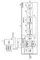
- FIG. 3 is a block diagram showing an example of the hardware configuration of the gas detection camera 1 in detail.
- the gas detection camera 1 is configured to include the non-visible light sensor NVSS and the visible light camera VSC.
- the non-visible light sensor NVSS is configured to include the control unit 11, the projection unit PJ, and the light reception processing unit SA.
- the control unit 11 is configured using, for example, a central processing unit (CPU), a micro processing unit (MPU), or a digital signal processor (DSP).
- the control unit 11 performs, for example, signal processing for totally controlling the operation control of each part of the invisible light sensor NVSS, input / output processing of data between the other parts, arithmetic processing of data, and storage processing of data. Do. Further, the control unit 11 sets a detection threshold M for detecting the gas GS to be detected by the non-visible light sensor NVSS in the detection processing unit 27.
- the control unit 11 sends a timing signal for AD conversion to the detection processing unit 27.
- the control unit 11 modulates the wavelength of the laser light LS emitted from the laser diode LD (for example, sweeps it within ⁇ predetermined width (for example, ⁇ 0. 0.5 nm) from the center frequency, see FIG. 5)
- the light source light emission signal of is sent to the laser diode LD.
- the control unit 11 receives a temperature control state signal from the detection processing unit 27, generates a temperature control signal based on the temperature control state signal, and sends the temperature control signal to the laser diode LD.
- the temperature adjustment control signal is a signal for adjusting the temperature of the laser light LS emitted from the laser diode LD, and is a signal instructing heat absorption or heat generation to a Peltier element (not shown) of the laser diode LD.
- the laser diode LD changes the central wavelength of the wavelength of the laser light LS according to the change in temperature according to the temperature control signal from the control unit 11.
- the control unit 11 refers to setting information (for example, information such as at which timing the emission direction of the laser beam LS or the light reception direction of the laser reflected light RV is switched) stored in the memory 13 (for example, semiconductor memory)
- a PTU (Pan Tilt Unit) control signal for controlling the drive of the pan and tilt unit 15 is generated and sent to the pan and tilt unit 15.
- the projection unit PJ constitutes a part of the pan and tilt unit 15, and includes a laser diode LD and a projection light source optical unit PLZ.
- the laser diode LD emits the laser light LS whose wavelength is adjusted so that the wavelength of the laser light LS matches the peak of the absorption wavelength band of the gas GS which is the detection target.
- a gas GS is a substance to be detected, given as an example methane gas (CH 4).
- the control unit 11 modulates the wavelength of the laser beam LS emitted from the laser diode LD by modulating the drive current of the laser diode LD as a semiconductor diode.
- the drive current is an input signal of the semiconductor diode, and the frequency corresponding to the alternating current of the drive current is the modulation frequency.
- a Peltier element (not shown) provided in the laser diode LD absorbs or generates heat in accordance with the temperature adjustment control signal from the control unit 11, and fluctuates the temperature of the laser diode LD, thereby centering the central wavelength of the wavelength of the laser light LS. adjust.
- the projection light source optical unit PLZ is configured using, for example, a collimator lens, and converts the laser light LS emitted from the laser diode LD into parallel light.
- the pan and tilt unit 15 pivots the camera platform on which the laser diode LD, the projection light source optical unit PLZ (for example, a collimating lens), the condenser lens CLZ, and the photodiode PD are mounted in the pan direction and the tilt direction.
- the pan and tilt unit 15 two-dimensionally scans within the scanning range of the detection space K by the laser light LS emitted from the laser diode LD.
- FIG. 4 is a block diagram showing in detail an example of the hardware configuration of the light reception processing unit.
- the light reception processing unit SA includes a condenser lens CLZ, a photodiode PD, a signal processing unit 26, a detection processing unit 27, and a display processing unit 28.
- the signal processing unit 26 includes an I / V conversion circuit 261, an amplification circuit 262, and a filter processing circuit 263.
- the detection processing unit 27 includes an AD conversion circuit 271, a temperature adjustment control processing unit 272, and a substance detection processing unit 273.
- the laser beam LS passes through the gas GS at any time while the laser beam LS wavelength-modulated to the detection space K is projected (irradiated) in the main scanning direction (see later) from the projection unit PJ.
- the reflector is, for example, a pipe or a valve disposed in the detection space K, or a wall, floor or ceiling of the detection space K.
- the temperature adjustment control processing unit 272, the substance detection processing unit 273, and the display processing unit 28 of the detection processing unit 27 are realized by the processor 20 executing the program stored in the memory 13. Also, the signal processing unit 26 and the AD conversion circuit 271 of the detection processing unit 27 may be similarly realized by the processor 20 executing the program held in the memory 13.
- the condensing lens CLZ is emitted from the laser diode LD, receives the laser reflected light RV in which a component of a specific wavelength is partially absorbed by the gas GS in the detection space K, and condenses it on the photodiode PD.
- the photodiode PD generates a charge according to the light amount of the laser reflected light RV received by the condensing lens CLZ, and outputs it as a current signal.
- the I / V conversion circuit 261 converts the current signal output from the photodiode PD into a voltage signal.
- the amplification circuit 262 amplifies the voltage signal output from the I / V conversion circuit 261.
- the filter processing circuit 263 filters the voltage signal amplified by the amplifier circuit 262 and outputs the filtered voltage signal to the AD conversion circuit 271 as a signal used for gas detection.
- the AD conversion circuit 271 converts the signal input from the signal processing unit 26 into a digital signal when detecting the gas GS or adjusting the temperature of the laser diode LD.
- the temperature adjustment control processing unit 272 generates a signal (temperature adjustment state signal) representing the temperature adjustment state based on the value converted into the digital value by the AD conversion circuit 271 in the temperature adjustment operation, and outputs the signal to the control unit 11 .
- This temperature control state signal is a signal indicating the magnitude (signal level) of a signal having a frequency (2 f) that is twice that of the signal (frequency f) of the wavelength-modulated laser beam LS emitted from the laser diode LD. It is.
- the temperature control state signal is twice the frequency f
- the temperature control state signal becomes a signal whose frequency fluctuates.
- the magnitude (signal level) of the signal of the frequency (2f) which is twice that of the frequency f obtained based on the signal from the photodiode PD is reduced.
- the substance detection processing unit 273 detects the presence or absence of the gas GS based on the value converted into the digital value by the AD conversion circuit 271 in the detection operation of the gas GS (see FIGS. 5 and 6). And a signal indicating the detection result of the presence or absence of the gas GS to the display processing unit 28.
- the substance detection processing unit 273 detects the presence or absence of the gas GS for each pixel constituting the gas position image (see below), and outputs a signal indicating the detection result of the presence or absence of the gas GS to the display processing unit 28. Do. Thereby, the display processing unit 28 can generate a gas position image indicating the detection result of the presence or absence of the gas GS for each pixel.
- the non-visible light sensor NVSS detects the presence or absence of the gas GS for each pixel in one line or gas position image in the horizontal or vertical direction that forms a gas position image (see below) (see below)
- the gas position image can be output to the monitor 150 earlier via the visible light camera VSC, as compared to the case where the gas position image is generated collectively for each frame. That is, the user who monitors the detection space K can quickly grasp whether or not there is a generation point of the gas GS in the detection space K.
- the substance detection processing unit 273 collects signals indicating the detection result of the presence or absence of the gas GS for each pixel for each line in the horizontal direction or the vertical direction that constitutes a gas position image (see below). It may be output to the display processing unit 28. In addition, the substance detection processing unit 273 collectively outputs a signal indicating the detection result of the presence or absence of the gas GS for each pixel in one frame of the entire gas position image (see below) and outputs the signal to the display processing unit 28. It is also good.
- the substance detection processing unit 273 is a signal of the wavelength-modulated laser light LS emitted from the laser diode LD based on the value converted into the digital value by the AD conversion circuit 271 as in the temperature control state signal.
- a signal indicating the magnitude (signal level) of the signal of the frequency (2f) that is twice that of (frequency 1f) is obtained.
- the substance detection processing unit 273 generates a signal indicating the detection result of the presence or absence of the gas GS based on whether or not a signal indicating the magnitude (signal level) of the signal of the double frequency (2f) is obtained. .
- the display processing unit 28 (an example of the detection processing unit) generates, from the non-visible light sensor NVSS, a gas position image that visually indicates the detection result (for example, a two-dimensional position) of the presence or absence of the gas GS in the detection space K .
- the display processing unit 28 uses a signal output each time from the substance detection processing unit 273 (that is, a signal indicating the detection result of the presence or absence of the gas GS for each pixel constituting the gas position image).
- a gas position image for each pixel is generated and output to the display control unit 37 of the visible light camera VSC.
- the display processing unit 28 when the display processing unit 28 outputs a signal for one line (that is, one line in the horizontal or main scanning direction to which the laser light LS is irradiated) from the substance detection processing unit 273. May generate a gas position image corresponding to the signal for one line and output it to the display control unit 37 of the visible light camera VSC.
- the display processing unit 28 when the signal for one frame (that is, one frame of the gas position image) is output from the substance detection processing unit 273, the display processing unit 28 outputs the gas position image corresponding to the signal for the one frame. It may be generated and output to the display control unit 37 of the visible light camera VSC.
- the gas position image is image data indicating the detection result of the presence or absence of the gas GS in the scan angle of view of the pan and tilt unit 15, and data of two-dimensional position information (for example, pan angle and tilt angle of camera platform) in the detection space K And.
- the display processing unit 28 outputs the gas position image to the display control unit 37 of the visible light camera VSC.
- the invisible light sensor NVSS provides the user with a visual sense of where in the detection space K the inside of the angle of view of the gas detection camera 1 (in other words, the scan angle of view of the pan and tilt unit 15) is present.
- the user is, for example, a manager of a gas company that dispatches an investigator of a gas company to the installation location of the gas detection camera 1 (for example, a piping room of a building, see FIG. 17). It is a person who monitors the generation position of the gas GS with a monitoring monitor (for example, a monitor 150 described later) or the like for the display data (see later described).
- the display processing unit 28 transmits a gas position image to the display control unit 37 in the visible light camera VSC, for example, a monitor 150, a camera server CS, and a communication terminal (not shown). For example, it may be transmitted to a smartphone or a tablet terminal owned by the user.
- the visible light camera VSC includes an imaging lens 31, an image sensor 33, a signal processing unit 35, a display control unit 37, and an output unit 38.
- the signal processing unit 35 and the display control unit 37 are realized by the processor 41 executing the program held in the memory 39.
- the imaging lens 31 has an imaging angle of view that generally includes the scanning angle of view of the pan-tilt unit 15 of the non-visible light sensor NVSS, and condenses incident light from the outside (that is, reflected light RM). Image on the imaging plane of
- the image sensor 33 has a peak of spectral sensitivity to the wavelength of visible light (for example, 0.4 ⁇ m to 0.7 ⁇ m).
- the image sensor 33 converts the optical image formed on the imaging surface into an electrical signal.
- the output of the image sensor 33 is input to the signal processing unit 35 as an electrical signal.
- the signal processing unit 35 generates a visible light image defined by, for example, RGB (Red Green Blue) or YUV (brightness and color difference) using an electric signal output from the image sensor 33. Thereby, a visible light image captured by the visible light camera VSC is formed. The signal processing unit 35 outputs the visible light image to the display control unit 37.
- the display control unit 37 detects the visible light image output from the signal processing unit 35 and the gas position image output from the display processing unit 28 when, for example, the gas GS is detected at a predetermined position in the visible light image. By superimposing and combining, display data (for example, an overlay image) is generated.
- the display control unit 37 may read and obtain a visible light image from the memory 39. According to the overlay image, the user specifies the location where the gas GS is generated in the visible light image captured by the visible light camera VSC by specifically connecting the object (for example, piping) shown in the visible light image. Yes, it is possible to find out the location of the gas GS early.
- the output unit 38 generates the UI screen WD1 (see FIGS. 17 and 18) including the display data (for example, overlay image) generated by the display control unit 37 and outputs the UI screen WD1 to an external device (for example, camera server CS and monitor 150) Do.
- the display data generated by the display control unit 37 is not limited to the overlay image, and a heat map image in which the visible light image is not shown (ie, display The gas position image itself (see heat map mode) sent from the processing unit 28 may be used, or the visible light image itself (see camera mode) may be used.
- the overlay image is limited to an image (see, for example, the overlay mode on the upper right of FIG.
- the overlay image is an image in which a local gas position image corresponding to only the pixel in which the gas GS is detected among all the pixels constituting the visible light image is superimposed (for example, detection in the lower right of FIG. See overlay mode).
- the camera server CS transmits display data (for example, overlay image) output from the display control unit 37 to a communication terminal (not shown) or one or more externally connected devices (not shown), and the communication terminal or one or more To prompt display of display data on the display screen of the externally connected device.
- display data for example, overlay image
- the monitor 150 is configured by using, for example, an LCD (Liquid Crystal Display) or an organic EL (Electroluminescence), and displays the display data output from the display control unit 37.
- the monitor 150 of the present embodiment may be configured using a touch panel that can receive an input operation (touch operation) of the user.
- an operation signal based on the input operation is, for example, a control unit of the gas detection camera 1 via a network (not shown). It is input to 11.
- the control unit 11 may determine, for example, the main scanning direction and the sub-scanning direction (see later) of the laser beam LS according to the operation signal.
- FIG. 5 is an explanatory view showing an example of the relationship between the wavelength of the emitted light and the light receiving voltage.
- methane gas CH 4
- the vertical axis in FIG. 5 represents the light receiving voltage (in which the unit is a normalized value) of the photodiode PD
- the horizontal axis in FIG. 5 represents the wavelength (nm: nanometer) of the laser reflected light RV received by the photodiode PD.
- the gas GS is present at a position where the absorption rate is high.
- the absorption characteristics of the gas GS are determined for each gas GS.
- the absorption spectrum of the gas GS has, for example, a wavelength band centered at 1653.67 nm.
- the laser beam LS emitted from the laser diode LD is modulated with a modulation width of 0.05 nm with the central wavelength of 165.67 nm as shown in the wavelength modulation range WAR0.
- the laser beam LS (that is, incident light whose wavelength is modulated) is emitted from the laser diode LD.
- the laser reflected light RV (that is, the received reflected light) in which the component of the specific wavelength is partially absorbed by the gas GS in the detection space K is the signal frequency (f1: modulation) of the laser light LS by the photodiode PD.
- the frequency (2f1) is twice that of the frequency (2f1). In this case, a sine wave signal having a constant frequency is output.
- FIG. 6 is an explanatory view showing a time change example of the wavelength characteristic of the wavelength-modulated laser light LS, and the characteristic of the light reception level of each reflected light when there is no methane gas and when there is a methane gas.
- the topmost wavelength modulation (f1) shows the wavelength characteristic of the output of the laser diode LD (that is, the laser light LS)
- the vertical axis shows the wavelength
- the horizontal axis shows time.
- the middle and lowermost light reception levels indicate signals (specifically, voltages) output from the photodiode PD in the absence and presence of methane gas, respectively.
- the signal received by the photodiode PD has a frequency (2f1) twice that of the modulation frequency (f1) of the laser light LS emitted from the laser diode LD when the gas GS is present. Therefore, the substance detection processing unit 273 detects the presence or absence of the gas GS based on the output signal of the AD conversion circuit 271 in the waveform of the output signal and has a signal of the frequency (2f1) twice the modulation frequency (f1). Determine if the property can be seen.
- the laser light LS emitted from the laser diode LD is a signal received by the photodiode PD, the laser emitted from the laser diode LD
- the doubled frequency (2f1) is 0 (zero) with respect to the modulation frequency (f1) of the light LS.
- the laser light LS is emitted after being wavelength-modulated by the modulation frequency f1 of a very large value.
- the wavelength modulation speed corresponding to the modulation frequency f1 (that is, the speed for sweeping the wavelength in the range of ⁇ 0.05 nm from the central wavelength) is a very large value, and compared to the scan speed of the pan tilt unit 15 described later. It is a fairly large value. Therefore, when emitting the laser light LS, the gas detection camera 1 needs to emit the light after wavelength-modulating the laser light LS at the modulation frequency f1 in a very short time.
- the gas detection camera 1 performs high-speed scanning in either the horizontal direction or the vertical direction in order to early determine whether the gas GS is present in the detection space K. This is to detect the presence or absence of the gas GS based on the wavelength characteristic of the received laser reflected light RV.
- the beam diameter of the laser beam LS is considerably larger than the length of one pixel of the gas position image for the purpose of detecting even when the gas GS which is the detection target of the gas detection camera 1 is present at a minimum. Small (see Figure 7).
- the gas detection camera 1 detects one pixel portion of the gas position image described later, the gas GS at one point in that one pixel
- the laser light LS which is wavelength-modulated by a number of multiple periods is irradiated to the one point.
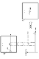
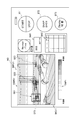
- FIG. 7 is an explanatory view schematically showing the beam diameter BRD of the laser light LS corresponding to m ⁇ n pixels forming one frame FRM of the gas position image.
- FIG. 8 is an explanatory diagram of the gas detection level in the first pixel IME in the m-th row and the n-th column. Both m and n are integers of 2 or more, m corresponds to the number of columns constituting one frame FRM, and n corresponds to the number of rows constituting one frame FRM.
- One frame FRM of the gas position image generated by the display processing unit 28 includes, for example, m ⁇ n pixels (that is, one pixel IME).
- the pixel in the n-th row in the m-th column is conveniently described as the “mn” or “mn” pixel.
- FIG. 7 exemplifies one pixel IME of “4-3” (that is, one pixel IME in the third row and the third row in the fourth column).
- the gas detection camera 1 according to the present embodiment generates the gas position image of the one-pixel IME by driving the pan and tilt unit 15 so that the laser light LS wavelength-modulated in the horizontal direction and the vertical direction (that is, FIG.
- the beam is irradiated at high speed with a beam diameter BRD in the direction from the left side to the right side of the drawing (see the lower left of the drawing in FIG. 7).
- the gas detection camera 1 has a direction in which the laser light LS is slightly inclined with respect to the pixels in the first row (that is, the pixels “1-1” to the pixels “m ⁇ 1”). The irradiation is performed while scanning in the horizontal and vertical directions so as to be SC1.
- the beam diameter of the wavelength-modulated laser beam LS is very small compared to the lateral length of one pixel IME having a rectangular shape (for example, a square). This is for the purpose of detecting even when the gas GS which is the detection target of the gas detection camera 1 is extremely present, as described in detail above.
- the laser beam LS when the laser beam LS is scanned in the direction SC1 and irradiated, the entire region of one pixel IME of “4-3” is irradiated with the laser beam LS. Rather, the laser beam LS is emitted only to a partial area (detection target area DTAR) having a substantially rectangular shape whose height is the length of the beam diameter BRD. In other words, in one pixel IME, the laser light LS is not irradiated (that is, there is a dead area where it is not determined whether the gas GS is detected).
- the gas detection camera 1 detects the presence or absence of the gas GS at an early stage, and pan and tilt so that the gas detection camera 1 irradiates the laser light LS to the entire area in one pixel IME.
- the drive of the unit 15 it takes time for the control.
- the gas detection camera 1 sets the maximum value of the gas detection level (see FIG. 9) of one pixel IME based on the wavelength characteristic of the laser reflected light RV when the laser light LS is irradiated in the direction SC1. It is calculated as a representative value of the detection result of the gas GS in the pixel IME (see the lower right of FIG. 8).
- a gas detection level (an example of a substance detection level) is, for example, in units of ppm-m (meters), and is obtained by the substance detection processing unit 273 from the light reception voltage based on a predetermined conversion formula.
- ppm-m is a unit indicating the concentration when 1 m of gas GS is present.
- the determination result of the presence or absence of the detection of the gas GS is discrete in the vertical direction.
- the resolution of the human eye for visually recognizing the visible light image on which the gas position image is superimposed is not good as compared with the resolution of a normal camera, for example, the presence or absence of detection of the gas GS only discretely in the vertical direction It is inferred that there is no particular problem in the determination of the presence or absence of the detection of the gas GS, even if it is not determined.
- the horizontal axis is the position of one pixel IME (in other words, the irradiation time of the laser light LS), and the vertical axis is the gas detection level in one pixel IME.
- a is the maximum value of the gas detection level
- b is the minimum value of the gas detection level. Therefore, the gas detection camera 1 calculates the representative value of the gas detection level in the one pixel IME of “mn” to be detected for the presence or absence of the gas GS as the maximum value a.
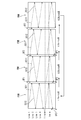
- FIG. 9 is a comparative explanatory view of the horizontal scan image of the laser light LS, the wavelength characteristics of the wavelength-modulated laser light LS, the signal intensity characteristics of the received laser reflected light RV, and the gas detection level.
- a gas free area NGSAR without gas GS and a gas free area GSAR with gas GS are shown in the detection space K.
- the scanning direction of the laser light LS is shown toward the direction.
- the horizontal axes of the graphs of the second stage to the fourth stage (lowermost stage) in FIG. 9 correspond to the positions of the non-gas area NGSAR and the gas presence area GSAR shown at the top of the figure.
- the vertical axis of the graph of the second stage of FIG. 9 shows the wavelength of the laser light LS
- the vertical axis of the graph of the third stage of the same figure shows the voltage of the laser reflected light RV (received voltage; see FIG. 5).
- the vertical axis of the fourth graph indicates the gas detection level.
- the gas detection level is calculated for each one-pixel IME constituting the gas position image, as described with reference to FIG. In the example of FIG.
- the voltage of the third stage and the gas detection level of the fourth stage in FIG. There is no Specifically, a signal at a frequency (2f1) twice that of the modulation frequency f1 is not detected at the third stage voltage of FIG. 9, and the substance detection processing unit 273 is set at the gas detection level of the fourth stage in FIG. A gas detection level which does not exceed the detected detection threshold M (not shown) is detected.
- FIG. 10 is an explanatory view schematically showing a detection target area DTAR of a gas GS and a dead area in each of m ⁇ n pixels constituting one frame FRM of a gas position image.
- FIG. 11 is a flow chart showing an example of the gas detection operation corresponding to the scan pattern shown in FIG.
- One frame FRM of the gas position image shown in FIG. 10 is composed of m ⁇ n one-pixel IMEs (see FIG. 7).
- the gas GS is detected in the detection angle K at the same angle of view as the angle of view when the visible light image is captured by the visible light camera VSC.
- a detection target area DTAR (see FIG. 7) to which the wavelength-modulated laser light LS is irradiated and the laser light LS is not irradiated in each of m ⁇ n 1-pixel IMEs constituting one frame FRM of the gas position image There is a dead zone.
- FIG. 7 A detection target area DTAR (see FIG. 7) to which the wavelength-modulated laser light LS is irradiated and the laser light LS is not irradiated in each of m ⁇ n 1-pixel IMEs constituting one frame FRM of the gas position image There is a dead zone.
- the gas detection camera 1 scans (scans) the laser light LS wavelength-modulated at high speed in the horizontal direction and drives it at low speed in the vertical direction by driving the pan and tilt unit 15. ).
- the wavelength-modulated laser light LS is determined to be the presence or absence of the detection of the gas GS with the detection target area DTAR for m being a total of n lines. Become. Therefore, although only detection of discrete gas GS is performed in the vertical direction, as described above, since the resolution of the human eye is lower than that of a normal camera, the laser is continuously continuous in the horizontal direction. Since the light LS is irradiated, it can be considered that the deterioration of the detection accuracy of the gas GS is suppressed.
- FIG. 10 shows an example in which the laser light LS is irradiated while scanning continuously in the horizontal direction at high speed, and the laser light LS is emitted discretely in the vertical direction. Is the same even if the horizontal direction and the vertical direction are interchanged. That is, although not illustrated in FIG. 10, in one frame FRM of the gas position image, the wavelength-modulated laser light LS is a line of n detection target areas DTAR in total of m lines. The presence or absence of detection may be determined. In this case, only the detection of the discrete gas GS is performed in the horizontal direction, but as described above, since the resolution of the human eye is lower than the resolution of a normal camera, the detection in the vertical direction is performed. Since the laser light LS is continuously irradiated, it can be considered that the deterioration of the detection accuracy of the gas GS is suppressed.
- the gas detection camera 1 emits the wavelength-modulated laser light LS from the projection unit PJ (S1), and controls the drive of the pan and tilt unit 15 based on the PTU control signal from the control unit 11.
- the vertical scan position control of the laser beam LS is started (S2), and the horizontal scan control is started (S3). That is, as shown in FIG. 10, the gas detection camera 1 scans the wavelength-modulated laser light LS slowly at a low speed in the vertical direction and at a high speed in the horizontal direction while capturing the visible light image Irradiate within the same angle of view.
- the gas detection camera 1 receives the laser reflected light RV, which is the reflected light of the laser light LS, by the photodiode PD via the condensing lens CLZ.
- the gas detection camera 1 amplifies the signal output from the photodiode PD in the signal processing unit 26 (S4).
- the gas detection camera 1 detects the gas GS detection process (in other words, gas detection process) based on the signal amplified in step S4 (in other words, the wavelength characteristic of the laser reflected light RV). It is executed in the part 27 (S5).
- the gas detection camera 1 determines whether the gas GS has been detected in step S5 (e.g., the result of determining whether the gas GS is detected per pixel described with reference to FIGS. 8 and 9).
- the processing for generating a gas position image (that is, the gas position image generation processing) is executed in the display processing unit 28 based on (S6).
- the details of the gas position image generation process of step S6 will be described later with reference to
- the gas detection camera 1 determines whether the irradiation position of the laser light LS has reached the end position of the horizontal scan position in the control unit 11 that controls the drive of the pan and tilt unit 15 (in other words, the laser in the horizontal direction) It is determined whether the scanning of the light LS is completed (S7).
- step S7 and step S9 will be briefly described.
- the control unit 11 acquires a drive control amount table (not shown) of the pan and tilt unit 15 stored in advance in the memory 13 and controls the drive of the pan and tilt unit 15 based on the drive control amount table.
- the drive control amount table for example, drive control corresponding to the start position to the end position of the horizontal scan position of the laser beam LS corresponding to the scan angle of view (see FIG. 2) determined for generating the gas position image.
- the amount and the drive control amount corresponding to the start position to the end position of the vertical scan position of the laser beam LS are stored. Therefore, based on the drive control amount table and the current drive control amount of the pan and tilt unit 15, the control unit 11 can determine whether the irradiation position of the laser light LS has reached the end position of the horizontal scan position.
- control unit 11 can determine whether the irradiation position of the laser light LS has reached the end position of the vertical scan position based on the drive control amount table and the current drive control amount of the pan and tilt unit 15 is there.
- the method of determining whether the irradiation position of the laser beam LS has reached the end position of the horizontal scan position or the vertical scan position is not limited to the method using the drive control amount table described above. . Further, this determination method can be applied to the determination methods of step S7A and step S9A shown in FIG.
- step S7 If scanning of the laser beam LS in the horizontal direction is not completed (S7, NO), the processing of the gas detection camera 1 returns to step S4, and steps S4 to S4 until scanning of the laser beam LS in the horizontal direction is completed.
- the process of S6 is repeated. In other words, when the laser beam LS is scanned at high speed in the horizontal direction, for example, the processing in steps S4 to S6 is performed while the laser beam LS is scanned at high speed in the horizontal direction.
- step S8 the gas detection camera 1 determines whether the irradiation position of the laser beam LS has reached the end position of the vertical scan position in the control unit 11 that controls the drive of the pan and tilt unit 15 (in other words, the laser in the vertical direction). It is determined whether the scanning of the light LS is completed (S9).
- step S9 If scanning of the laser light LS in the vertical direction is not completed (S9, NO), the processing of the gas detection camera 1 returns to step S3, and steps S3 to S3 until scanning of the laser light LS in the vertical direction is completed.
- the process of S6 is repeated. In other words, when the laser beam LS is slowly scanned in the vertical direction, for example, the processing in steps S3 to S6 is performed while the laser beam LS is slowly scanned in the vertical direction.
- the gas detection camera 1 determines that the scanning of the laser beam LS in the vertical direction is completed (S9, YES), the scanning of the laser beam LS in the vertical direction is stopped (S10). Thus, the irradiation of the laser light LS for one frame FRM of the gas position image is completed.
- imaging for example, imaging of a visible light image
- the process of the gas detection camera 1 returns to step S2.
- the gas GS detection process does not need to be executed.
- the processing of the detection camera 1 ends.
- FIG. 12 is a flowchart showing an example of the gas position image generation process of step S6 of FIG. 11 in detail.
- the gas position image generation process shown in FIG. 12 is executed, for example, with one pixel forming the gas position image as a processing target pixel.
- the display processing unit 28 sets a processing target pixel (for example, one pixel forming the gas position image) of the gas position image generation process (S6-1).
- the display processing unit 28 acquires (inputs) the gas detection level of the processing target pixel set in step S6-1 based on the output from the detection processing unit 27 (S6-2).
- the display processing unit 28 sets the gas detection level of the processing target pixel in the current frame (current frame) set in step S6-1 and the same corresponding processing target pixel in the frame (previous frame) immediately before the current frame.
- the gas detection level is compared (S6-3). If the display processing unit 28 determines that the gas detection level of the processing target pixel in the current frame is higher than the gas detection level of the same corresponding processing target pixel in the previous frame (S6-3, YES), the gas in the current frame A process of generating a gas position image at the processing target pixel is executed based on the detection level (S6-4).
- the display processing unit 28 determines that the gas detection level of the processing target pixel in the current frame is lower than or equal to the gas detection level of the same corresponding processing target pixel in the previous frame (S6-3, NO), It is determined that the gas position image in the same processing target pixel in the frame is maintained and used (S6-5).
- step S6-4 or step S6-5 the display processing unit 28 determines that the current processing target pixel (that is, the one set in step S6-1) is the laser beam LS in the horizontal direction or the main scanning direction of the gas position image. It is determined whether or not it is the end pixel (final pixel) in the scan of (S6-6). If the display processing unit 28 determines that the current processing target pixel is the end pixel (final pixel) in the scanning (scanning) of the laser beam LS in the horizontal direction or the main scanning direction of the gas position image (S6- 6, YES), the gas position image generation process shown in FIG. 12 is ended. After this, although not shown in FIG.
- the display processing unit 28 outputs the gas position image of one pixel generated or determined to be used in step S6-4 or step S6-5 to the display control unit 37.
- the display control unit 37 superimposes (overlays) the position of the corresponding pixel of the visible light image displayed on the monitor 150 every time the gas position image of one pixel sent from the display processing unit 28 is acquired. Do.
- the display processing unit 28 determines that the current processing target pixel is not the end pixel (final pixel) in the scanning (scanning) of the laser beam LS in the horizontal direction or the main scanning direction of the gas position image ( S6-6, NO)
- a processing target pixel next to the current processing target pixel (for example, a pixel adjacent to the current processing target pixel) is set (S6-1). Therefore, steps S6-1 to S6 are performed until it is determined that the current processing target pixel is the end pixel (final pixel) in the scanning (scanning) of the laser beam LS in the horizontal direction or main scanning direction of the gas position image.
- the processing up to -6 is repeated.
- the gas detection camera 1 immediately generates the gas position image corresponding to the detection result of the presence or absence of the gas GS for each pixel by executing the gas position image generation process shown in FIG.
- the user who monitors the detection space K can quickly grasp whether or not there is a generation point of the gas GS in the detection space K.
- FIG. 13 is a pattern explanatory view showing a first example of a scan pattern of laser light LS to which a predetermined amount of offsets OF1, OF2, and OF3 are applied in the vertical direction.
- FIG. 14 is a flow chart showing an example of the gas detection operation corresponding to the scan pattern shown in FIG.
- the gas position image generation process (step S6) in FIG. 14 is the same process as that in FIG.
- FIG. 13 four one-frame FRM of the gas position image (that is, four frames of the gas position image) is taken as a unit, and irradiation of laser light LS in the vertical direction (vertical direction in FIG. 13) in each one-frame FRM.
- the laser beam LS is irradiated so that the position is slightly shifted.
- the position of the upper left end of one frame FRM in FIG. 13 is the start position of the scanning in the horizontal direction and the vertical direction of the laser light LS.
- the laser beam LS is repeatedly irradiated in the horizontal direction (precisely, in the order of the direction SC11 slightly inclined to the direction SC12 ⁇ the direction SC12) without giving the offset in the vertical direction from the start position.
- the size of the offset OF3 may be the sum of the size of the offset OF1 and the size of the offset OF2.
- the gas detection camera 1 can repeat the process of determining the presence or absence of the detection of the gas GS by irradiating the laser light LS repeatedly in the order of direction SC11 ⁇ direction SC12 in units of 4 frames.
- the gas detection camera 1 controls whether the correction of the irradiation position (vertical position) in the vertical direction of the laser beam LS is performed for the next one frame (for example, the second frame) after step S10. In (S12). When correction of the irradiation position (vertical position) in the vertical direction of the laser beam LS is not performed for the next one frame (S12, NO), the vertical position of the laser beam LS is initially set to correspond to the next frame. The processing of the gas detection camera 1 returns to step S2 in order to realize this.
- the control unit 11 executes offset processing for applying a predetermined amount of offset to the start position of the scan in the vertical direction of the light LS (S13).
- step S13 for example, the control unit 11 applies the offset OF1 in the second frame, applies the offset OF2 in, for example, the third frame, and applies the offset OF3 in, for example, the fourth frame (see FIG. 13).
- the gas detection camera 1 determines whether the offset application position given to the start position of the vertical scan in step S13 is a predetermined final position (for example, the application position of the offset OF 3) (S14) ). If the offset application position is not a predetermined final position (for example, an offset OF3 application position) (S14, NO), in order to initialize the vertical position of the laser beam LS to correspond to the next one frame, The processing of the gas detection camera 1 returns to step S2.
- a predetermined final position for example, the application position of the offset OF 3
- step S13 determines that the application position of the offset given to the start position of the vertical scan in step S13 is the predetermined final position (for example, the application position of the offset OF3) (S14, YES
- the amount of offset to the start position of the vertical scan is set to a predetermined initial value (for example, zero) (S15).
- the process following step S15 is step S11, which is the same as that of FIG.
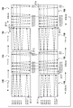
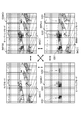
- FIG. 15 is a pattern explanatory view showing a first example of a scan pattern of laser light LS which alternately repeats horizontal high-speed scan and vertical high-speed scan every one frame FRM.
- FIG. 16 is a pattern diagram showing a second example of a scan pattern of laser light LS alternately repeating horizontal high-speed scan and vertical high-speed scan every one frame FRM.
- four one-frame FRM of the gas position image (that is, four frames of the gas position image) is a unit, and the main scanning direction of the laser light LS (that is, the laser light LS continuously) for each one frame FRM.
- the direction in which the light is irradiated while being scanned (the same applies hereinafter) switches between the horizontal direction and the vertical direction.
- the position of the upper left end of one frame FRM in FIG. 15 is the start position of the scanning in the horizontal direction and the vertical direction of the laser light LS. From the start position, the laser beam LS is repeatedly irradiated in the horizontal direction (more precisely, in the order of the direction SC11 ⁇ direction SC12 which is slightly inclined).
- the first frame as a result of scanning in the direction SC11 m (in the description of FIGS. 15 and 16, m: an even number of 2 or more) / 2 times and scanning in the direction SC12 m / 2 times, a total of m times laser light
- the LS is scanned in a substantially horizontal direction.
- the final position of the scan position of the laser light LS in the first frame is the start position of the scan position of the laser light LS in the next 1 frame FRM (ie, the second frame) It has become.
- the gas detection camera 1 can minimize the drive control amount of the pan and tilt unit 15 for each one frame FRM of the gas position image, so that the detection process of the gas GS can be continuously performed.
- the position of the lower left end of one frame FRM in FIG. 15 is the start position of the horizontal and vertical scan of the laser light LS.
- the laser beam LS is repeatedly irradiated in the vertical direction (more precisely, in the order of the direction SC21 ⁇ the direction SC22 inclined slightly obliquely).
- SC21 n n: 2 or more even number in the description of FIGS. 15 and 16
- SC22 n / 2 times a total of n times
- the LS is scanned in a substantially vertical direction.
- the final position of the scan position of the second frame laser light LS (ie, the position of the lower right end of the one frame FRM) is the start of the scan position of the laser light LS in the next one frame FRM (ie, the third frame) It is in position.
- the gas detection camera 1 can minimize the drive control amount of the pan and tilt unit 15 for each one frame FRM of the gas position image, so that the detection process of the gas GS can be continuously performed.
- the position of the lower right end of one frame FRM in FIG. 15 is the start position of the horizontal and vertical scan of the laser light LS. From the start position, the laser beam LS is repeatedly irradiated in the vertical direction (more precisely, in the order of the direction SC13 ⁇ direction SC14 slightly inclined). In the third frame, as a result of scanning m / 2 times in the direction SC13 and m / 2 times in the direction SC14, the laser light LS is scanned substantially horizontally in a total of m times.
- the final position of the scan position of the third frame laser light LS (that is, the position of the upper right end of the one frame FRM) is the start position of the scan position of the laser light LS in the next one frame FRM (that is, the fourth frame) It has become.
- the gas detection camera 1 can minimize the drive control amount of the pan and tilt unit 15 for each one frame FRM of the gas position image, so that the detection process of the gas GS can be continuously performed.
- the position of the upper right end of one frame FRM in FIG. 15 is the start position of the horizontal and vertical scan of the laser light LS. From the start position, the laser beam LS is repeatedly irradiated in the vertical direction (more precisely, in the order of the direction SC23 ⁇ direction SC24 inclined slightly obliquely). In the fourth frame, as a result of scanning in the direction SC23 n / 2 times and scanning in the direction SC24 n / 2 times, the laser light LS is scanned in the substantially vertical direction a total of n times.
- the final position of the scan position of the laser light LS of the fourth frame (that is, the position of the upper left end of the one frame FRM) is the start position of the scan position of the laser light LS in the next one frame FRM (that is, the fifth frame) It has become.
- the gas detection camera 1 can minimize the drive control amount of the pan and tilt unit 15 for each one frame FRM of the gas position image, so that the detection process of the gas GS can be continuously performed.
- eight one-frame FRM of the gas position image (that is, eight frames of the gas-position image) is a unit, and the main scanning direction of the laser light LS (that is, the laser light LS continuously) every one frame FRM.
- the direction in which the light is irradiated while being scanned (the same applies hereinafter) switches between the horizontal direction and the vertical direction.
- the position of the upper left end of one frame FRM in FIG. 16 is the start position of the scanning in the horizontal direction and the vertical direction of the laser light LS. From the start position, the laser beam LS is repeatedly irradiated in the horizontal direction (more precisely, in the order of a diagonally lower right direction ⁇ a diagonal lower left direction which is slightly inclined). In the first frame, as a result of scanning m / 2 times in the obliquely lower right direction and scanning m / 2 times in the obliquely lower left direction, the laser light LS is scanned substantially horizontally in a total of m times.
- the gas detection camera 1 moves the pan / tilt unit 15 with respect to the start position of the irradiation of the laser beam LS of the second frame only by providing the offset OF11 of a predetermined amount from the final position of the scan position of the first frame.
- the amount can be reduced, and the detection process of the gas GS can be performed continuously.
- the position of the lower left end of one frame FRM in FIG. 16 is the start position of the horizontal and vertical scan of the laser light LS.
- the laser beam LS is repeatedly emitted in the vertical direction (more precisely, in the order of a diagonally upper right direction ⁇ a diagonal lower right direction slightly inclined).
- the laser light LS is scanned in the substantially vertical direction a total of n times.
- the position where a predetermined amount of offset OF12 is given in the horizontal right direction from the final position of the scan position of the second frame laser light LS (that is, the position of the lower right end of one frame FRM) is the next one frame FRM ( That is, it is the start position of the scan position of the laser beam LS in the third frame).
- the gas detection camera 1 moves the pan / tilt unit 15 with respect to the start position of the irradiation of the laser beam LS of the third frame only by providing the offset OF12 of a predetermined amount from the final position of the scan position of the second frame.
- the amount can be reduced, and the detection process of the gas GS can be performed continuously.
- the position of the lower right end of one frame FRM in FIG. 16 is the start position of the scanning in the horizontal direction and the vertical direction of the laser light LS. From the start position, the laser light LS is emitted repeatedly in the horizontal direction (more precisely, in the order of the upper left direction and the upper right direction inclined slightly obliquely). In the third frame, as a result of scanning m / 2 times obliquely in the upper left direction and m / 2 times in the obliquely upper right direction, the laser light LS is scanned substantially horizontally in a total of m times.
- the position where a predetermined amount of offset OF13 is given vertically upward from the final position of the scan position of the third frame laser light LS (that is, the position of the upper right end of one frame FRM) is the next one frame FRM (that is, , And the start position of the scan position of the laser beam LS in the fourth frame).
- the gas detection camera 1 moves the pan / tilt unit 15 with respect to the start position of the irradiation of the laser beam LS of the fourth frame only by providing the offset OF13 of the predetermined amount from the final position of the scan position of the third frame.
- the amount can be reduced, and the detection process of the gas GS can be performed continuously.
- the position of the upper right end of one frame FRM in FIG. 16 is the start position of the scanning in the horizontal direction and the vertical direction of the laser light LS. From the start position, the laser beam LS is repeatedly emitted in the vertical direction (more precisely, in the order of a diagonally lower left direction and then an upper left direction slightly inclined). In the fourth frame, as a result of scanning n / 2 times in the lower left diagonal direction and scanning n / 2 times in the upper left diagonal direction, the laser light LS is scanned in the substantially vertical direction a total of n times.
- the position where a predetermined amount of offset OF14 is given in the horizontal left direction from the final position of the scan position of the laser light LS of the fourth frame (that is, the position of the upper left end of one frame FRM) is the next one frame FRM (that is, , And the start position of the scan position of the laser beam LS before the application of the additional offset OF11 in the fifth frame).
- the gas detection camera 1 moves the pan / tilt unit 15 with respect to the start position of the irradiation of the laser beam LS of the fifth frame only by providing the offset OF14 of the predetermined amount from the final position of the scan position of the fourth frame.
- the amount can be reduced, and the detection process of the gas GS can be performed continuously.
- the position where the additional offset OF11 is added from the position of the upper left end of one frame FRM in FIG. 16 is the start position of the horizontal and vertical scan of the laser light LS.
- the laser beam LS is repeatedly irradiated in the horizontal direction (more precisely, in the order of a diagonally lower right direction ⁇ a diagonal lower left direction which is slightly inclined).
- the laser light LS is scanned substantially horizontally in a total of m times.
- the start position of the scan position of the laser beam LS in the next one frame FRM (that is, the second frame) at a position where the further offset OF12 is given in the horizontal right direction from the final position of the scan position of the fifth frame laser beam LS. It has become.
- the gas detection camera 1 moves the pan / tilt unit 15 with respect to the start position of the irradiation of the laser beam LS of the sixth frame only by providing the offset OF11 of a predetermined amount from the final position of the scan position of the fifth frame. The amount can be reduced, and the detection process of the gas GS can be performed continuously.
- the position where the additional offset OF12 is given in the horizontal right direction from the position of the lower left end of one frame FRM in FIG. 16 is the start position of the horizontal and vertical scan of the laser light LS. It becomes. From the start position, the laser beam LS is repeatedly emitted in the vertical direction (more precisely, in the order of a diagonally upper right direction ⁇ a diagonal lower right direction slightly inclined). In the sixth frame, as a result of scanning n / 2 times in the obliquely upper right direction and scanning n / 2 times in the obliquely lower right direction, the laser light LS is scanned in the substantially vertical direction a total of n times.
- the start position of the scan position of the laser beam LS in the next one frame FRM (that is, the seventh frame) to which the additional offset OF13 is given in the vertically upward direction from the final position of the scan position of the sixth frame laser beam LS. It has become.
- the gas detection camera 1 moves the pan / tilt unit 15 with respect to the start position of the irradiation of the laser beam LS of the seventh frame only by providing the offset OF13 of the predetermined amount from the final position of the scan position of the sixth frame. The amount can be reduced, and the detection process of the gas GS can be performed continuously.
- the position where the additional offset OF13 is given in the vertically upward direction from the position of the lower right end of one frame FRM in FIG. 16 is the start of the horizontal and vertical scan of the laser light LS. It becomes a position. From the start position, the laser light LS is emitted repeatedly in the horizontal direction (more precisely, in the order of the upper left direction and the upper right direction inclined slightly obliquely). In the seventh frame, as a result of scanning m / 2 times obliquely in the upper left direction and scanning m / 2 times in the obliquely upper right direction, the laser light LS is scanned substantially horizontally in a total of m times.
- the start position of the scan position of the laser beam LS in the next one frame FRM (that is, the eighth frame) at which the position where the additional offset OF14 is given in the horizontal left direction from the final position of the scan position of the seventh frame laser beam LS It has become.
- the gas detection camera 1 moves the pan / tilt unit 15 with respect to the start position of the irradiation of the laser beam LS of the eighth frame only by providing the offset OF14 of the predetermined amount from the final position of the scan position of the seventh frame. The amount can be reduced, and the detection process of the gas GS can be performed continuously.
- the position where the additional offset OF14 is given in the horizontal left direction from the position of the upper right end of one frame FRM in FIG. 16 is the start position of the horizontal and vertical scan of the laser light LS. It becomes. From the start position, the laser beam LS is repeatedly emitted in the vertical direction (more precisely, in the order of a diagonally lower left direction and then an upper left direction slightly inclined). In the eighth frame, as a result of scanning n / 2 times in the lower left diagonal direction and scanning n / 2 times in the upper left diagonal direction, the laser light LS is scanned in the substantially vertical direction a total of n times.
- the final position of the scan position of the laser light LS of the eighth frame (that is, the position of the upper left end of the one frame FRM) is the start position of the scan position of the laser light LS in the next one frame FRM (that is, the ninth frame) It has become.
- the gas detection camera 1 can use the final position of the scan position of the eighth frame as the start position of the irradiation of the laser light LS of the ninth frame, the movement amount of the pan and tilt unit 15 can be reduced, and the gas is continuously transmitted. It can execute GS detection processing.
- FIG. 16A is an explanatory view showing a determination example of horizontal high-speed scan based on a user operation.
- FIG. 16B is an explanatory view showing an example of determination of vertical high-speed scan based on user operation.
- a frame SLAR1 in the shape of a rectangle is designated by user operation on the monitor 150 (eg, touch panel)
- the control unit 11 determines (determines) that the high-speed scan is to be performed in the lateral direction which is the longitudinal direction of the rectangle.
- the designation based on the user operation may be a touch operation of the user on the monitor 150 or a designation based on a cursor CSR using a mouse (not shown).
- the gas detection camera 1 can easily determine the main scanning direction of the wavelength-modulated laser light LS by a simple user operation of designating a rectangular shape whose longitudinal direction can be easily determined.
- a frame SLAR2 in the shape of a rectangle (eg, rectangle) is designated by user operation on the monitor 150 (eg, touch panel)
- the control unit 11 determines (determines) that the high-speed scan is to be performed in the vertical direction which is the longitudinal direction of the rectangle.
- the gas detection camera 1 can easily determine the main scanning direction of the wavelength-modulated laser light LS by a simple user operation of designating a rectangular shape whose longitudinal direction can be easily determined.
- FIG. 17 is a flowchart showing an example of the gas detection operation corresponding to the scan pattern shown in FIG. 15 or FIG.
- the gas position image generation process (step S6) in FIG. 17 is the same process as that in FIG.
- step S1A the gas detection camera 1 sets the scan (scanning) direction of the laser light LS in the frame in the current processing target in the frame (S1A).
- the process of step S1A may be performed before step S1.
- the control unit 11 sets the horizontal direction in the main scanning direction and the vertical direction in the sub-scanning direction in the frame currently being processed.
- the default scan direction and scan start point previously stored in the memory may be set.
- the setting may also be changed.
- the gas detection camera 1 controls the scan position control of the laser beam LS in the sub-scanning direction (for example, the vertical direction) by controlling the drive of the pan and tilt unit 15 based on the PTU control signal from the control unit 11. It starts (S2A), and further starts scan control in the main scanning direction (for example, the horizontal direction) (S3A). That is, as shown in FIG. 15 or FIG. 16, the gas detection camera 1 scans the wavelength-modulated laser light LS at low speed in the vertical direction and at high speed in the horizontal direction while capturing visible light image It irradiates within the same angle of view as the angle of view of
- step S4 to step S6 the gas detection camera 1 determines whether the irradiation position of the laser light LS has reached the end position of the main scanning position in the control unit 11 that controls the drive of the pan and tilt unit 15 (in other words, It is determined whether the scanning of the laser beam LS in the main scanning direction is completed (S7A).
- the process of the gas detection camera 1 returns to step S4, and the process continues until the scanning of the laser beam LS in the main scanning direction is completed.
- the processes of S4 to S6 are repeated. In other words, when the laser light LS is scanned at high speed in the main scanning direction, for example, the processing in steps S4 to S6 is performed while the laser light LS is scanned at high speed in the main scanning direction.
- the gas detection camera 1 stops the scanning of the laser light LS in the main scanning direction (S8A).
- the gas detection camera 1 controls the drive of the pan / tilt unit 15 in the control unit 11 to determine whether the irradiation position of the laser light LS has reached the end position of the sub scanning position (in other words, the sub scanning direction It is determined whether the scanning of the laser light LS has ended (S9A).
- the processing of the gas detection camera 1 returns to step S3A and continues until the scanning of the laser beam LS in the sub scanning direction is completed.
- the processes of S3A to S6 are repeated. In other words, when the laser light LS is scanned at low speed in the sub scanning direction, for example, the processing in steps S3A to S6 is performed while the laser light LS is scanned at low speed in the sub scanning direction.
- the gas detection camera 1 stops the scanning of the laser beam LS in the sub-scanning direction (S10A).
- the gas detection camera 1 sets the scanning (scanning) direction of the laser beam LS in the next frame in the next frame of the current processing target frame (S11A) .
- the control unit 11 sets the vertical direction as the main scanning direction and sets the horizontal direction as the sub-scanning direction in the current frame to be processed.
- the gas detection camera 1 determines in the control unit 11 whether or not the irradiation position of the laser beam LS in the sub-scanning direction is to be corrected for the next frame (for example, the second frame) (S12A). If correction of the irradiation position in the sub scanning direction of the laser beam LS is not performed for the next one frame (S12A, NO), the processing of the gas detection camera 1 returns to step S2A and the laser beam LS of the next one frame Resume scanning.
- the control unit 11 executes offset processing for applying a predetermined amount of offset to the start position of the scan in the scanning direction (S13A).
- step S13A for example, the control unit 11 assigns an offset OF11 in the first and fifth frames, an offset OF12 in the second and sixth frames, and assigns an offset OF13 in the third and seventh frames, for example In the eighth frame, an offset OF14 is given (see FIG. 16).
- the gas detection camera 1 determines whether the application position of the offset given to the start position of the scan in the sub scanning direction at step S13A is a predetermined final position (for example, the application position of the offset OF 14) S14).
- the processing of the gas detection camera 1 returns to step S2A and is set in step S11A.
- the scanning of the laser beam LS is resumed from the main scanning direction of the laser beam LS, the start position thereof, the sub-scanning direction and the start position thereof.
- the gas detection camera 1 determines that the application position of the offset given to the start position of the scan in the vertical direction in step S13A is the predetermined final position (for example, the application position of the offset OF14 for the eighth frame) (S14, YES)
- the amount of offset to the start position of the scan in the sub-scanning direction is set to a predetermined initial value (for example, zero) (S15A).
- a predetermined initial value for example, zero
- step S15A If imaging (for example, imaging of a visible light image) is continued in the gas detection camera 1 after step S15A (S11, YES), the processing of the gas detection camera 1 returns to step S1A, and the processing target frame Setting the scanning direction of the laser beam LS in At this time, the default scanning direction and scanning start point stored in advance in the memory may be set.
- imaging for example, imaging of a visible light image
- the gas GS detection process does not need to be executed. The processing of the detection camera 1 ends.
- FIG. 17 is a diagram showing a first example of the UI screen WD1 displaying the overlay image IMPO1 in which the gas position image GSMG1 is superimposed on the visible light image IMG11.
- FIG. 18 is a view showing a second example of the UI screen WD1 displaying the overlay image IMPO2 in which the gas position image GSMG1 is superimposed on the visible light image IMG11.
- FIG. 19 is an explanatory view showing an example of switching of the display mode of the image displayed on the UI screen WD1.
- the UI screen WD1 shown in FIGS. 17 and 18 is generated by, for example, the output unit 38 of the gas detection camera 1 and displayed on the monitor 150.
- the overlay image IMPO1 is an example of display data generated by the display control unit 37 of the gas detection camera 1, and more specifically, a visible light image IMG11 captured by the visible light camera VSC. Is an image generated by superposing the gas position image GSMG1.
- the user visually recognizes, for example, the overlay image IMPO1 displayed on the monitor 150, in a visible light image (for example, a piping room of a building) captured by the gas detection camera 1, a gas which is difficult to be directly reflected in the visible light image It is possible to visually and intuitively recognize the occurrence of GS.
- a visible light image for example, a piping room of a building
- the positions of the respective gases GS1, GS2, and GS3 are displayed as a heat map according to the gas detection level. For example, by using a heat map in which the high concentration is red and the low concentration is blue, the gas detection levels of the gases GS1 to GS3 (see FIG. 8, that is, the concentration of the gas GS) can be visually and intuitively discriminated. .
- the scale of the heat map is indicated by, for example, the heat map bar SMP1 displayed on the UI screen WD1.
- the gas detection camera 1 is in the middle of executing determination processing of the presence or absence of the detection of the gas GS corresponding to the entire one frame of the visible light image IMG11. Therefore, in the overlay image IMPO1 shown in FIG. 17, the pixel area DT1 for which the process of determining the presence or absence of the detection of the gas GS has been performed and the process of determining the presence or absence of the detection of the gas GS in the entire one frame of the gas position image GSMG1. The unexecuted pixel area NDT1 is shown.
- the top ten pixels having the high concentration of the gas GS in the pixel area DT1 are the start / stop button BT1, the snapshot button BT2, the display switching button BT3, the gas concentration display area NM1, and the pixel area DT1.
- a position information column MX1 is displayed.
- the gas detection camera 1 When the start / stop button BT1 is pressed by a user operation, the gas detection camera 1 simultaneously starts (starts) or simultaneously stops (stops) detection processing of presence / absence of detection of gas GS and imaging processing of visible light image ) Give instructions.
- the gas detection camera 1 When the snapshot button BT2 is pressed by a user operation, the gas detection camera 1 is instructed to save a snapshot of the overlay images IMPO1 and IMPO2 when pressed in a memory (for example, the memory 39).
- the display mode of the image displayed on the UI screen WD1 generated by the output unit 38 for the gas detection camera 1 is a camera mode corresponding to the visible light image IMG11.
- the gas concentration display area NM1 is the largest in the pixel region DT1 for which the determination processing of the presence or absence of the detection of the gas GS has been performed or the highest concentration of the gas GS in the region USAR1 (see FIG. 18) designated by user operation. Display the value.
- the unit of the gas GS is ppw-m (meters) as described above, but is not limited thereto.
- the information column MX1 shows the top ten largest high-density gas GSs in the pixel area DT1 for which the process of judging the presence or absence of the detection of the gas GS has been executed or the area USAR1 (see FIG. 18) designated by the user operation.
- the information on the pixel position is, for example, the value of the gas detection level, and the X coordinate and the Y coordinate indicating the position of the gas GS in the gas position image.
- the gas detection camera 1 has already performed the process of determining the presence or absence of the detection of the gas GS corresponding to the entire one frame of the visible light image IMG11. Therefore, in the overlay image IMPO2 shown in FIG. 18, the pixel region DT2 for which the process of determining the presence or absence of the detection of the gas GS has been performed is shown in the entire one frame of the gas position image GSMG1.
- a region USAR1 of a part of the overlay image IMPO2 is designated by user operation.
- the output unit 38 of the gas detection camera 1 sets the maximum value of the highest concentration of the gas GS in the specified area USAR1.
- the information is displayed in the gas concentration display area NM1, and further, information on the upper ten largest pixel positions where the concentration of the gas GS is high is displayed in the information column MX2.
- one of the camera mode, the overlay mode, the heat map mode, and the detection overlay mode is designated by pressing the display switching button BT3 based on the user operation.
- an operation signal based on the designation operation is input to the control unit 11 of the gas detection camera 1.
- the control unit 11 instructs the output unit 38 to generate a UI screen including an image corresponding to any of the display modes based on the input operation signal.
- the output unit 38 can generate the UI screen WD1 in which one of the visible light image IMG11, the overlay image IMPO2, the heat map image (that is, the gas position image GSMG1), and the overlay image IMPO3 is selected.
- the user can confirm the state before the start of the determination process of the presence or absence of the detection of the gas GS and, for example, the state before the start by pressing the snapshot button BT2. Can be stored in the gas detection camera 1.
- the user can use the contents of the gas position image GSMG1 obtained based on the completion of the process of determining the presence or absence of the detection of the gas GS as the visible light image IMG11 as a background image. It can be confirmed in detail in light of the content.
- the user can simply generate the position where the gas GS is generated, with the contents of the visible light image IMG11 serving as the background image being omitted. It can be determined early in the position image.
- the user detects the gas concentration of a predetermined amount in the gas position image GSMG1 obtained based on the completion of the process of determining the presence or absence of the gas GS. , And can be confirmed in detail in comparison with the content of the visible light image IMG11 as the background image. Therefore, the user can accurately view only the detected portion of the gas GS exceeding the predetermined amount without degrading the visibility of the visible light image IMG11 as compared to the overlay image IMPO2 corresponding to the overlay mode. You can check it against the contents of
- the gas detection camera 1 holds the visible light image of the detection space K (an example of the detection area) of the substance in the memory 39, and the laser light from the laser diode LD in the detection space K (first (One example of non-visible light) is wavelength-modulated and emitted from the projection part PJ in the horizontal direction and the vertical direction.
- the laser reflected light RV in which the wavelength-modulated laser light LS transmits the gas GS and is reflected by the reflector in the background in other words, the component of a specific wavelength by the gas GS Is received by the condensing lens CLZ (an example of the light receiving unit).
- the gas detection camera 1 changes the emission direction of the laser light LS in the projection unit PJ and the light reception direction of the laser reflected light RV in the condensing lens CLZ in the pan / tilt unit 15 (an example of an actuator).
- the gas detection camera 1 displays a gas position image (an example of a substance position image) indicating the detection result of the presence or absence of the gas GS in the detection space K based on the signal intensity frequency characteristic of the laser reflected light RV (detection) Generated in an example of the processing unit).
- the gas detection camera 1 is a representative value indicating detection results of m (m: integer of 2 or more) ⁇ n (n: integer of 2 or more) single pixels constituting one frame of the visible light image and the gas position image. The respective calculation results are superimposed on corresponding pixels of the visible light image and displayed on the monitor 150.
- the gas detection camera 1 determines the gas position image in view of the frequency characteristic appearing in the signal of the laser reflected light RV with respect to the laser light LS wavelength-modulated centering on the wavelength in consideration of the absorption characteristic of the substance (for example, gas GS). It is possible to obtain the detection result of the presence or absence of the gas GS of each one pixel to be configured.
- the substance for example, gas GS
- the gas detection camera 1 roughly calculates the representative value indicating the detection result of the presence or absence of the gas GS in the one pixel, not the detection result of the presence or absence of the gas GS in each whole pixel constituting the gas position image Therefore, it is possible to simultaneously suppress the deterioration of the detection accuracy of the gas GS existing in the detection space K and the early detection of the gas GS existing in the detection space K.
- the beam diameter of the laser light LS emitted from the gas detection camera 1 is smaller than the size of one m ⁇ n pixels forming the gas position image.
- the gas detection camera 1 emits the laser beam LS having a beam diameter smaller than the size of one pixel only to a partial area (the detection target area DTAR) to which the laser beam LS irradiated in one pixel is irradiated.
- the detection sensitivity of the presence or absence of the gas GS corresponding to the SN ratio of the gas position image can be improved.
- the gas detection camera 1 sets the horizontal direction or the vertical direction in each of m ⁇ n one pixels as the main scanning direction of the laser light LS, the laser at a plurality of consecutive points (irradiation positions) in one pixel Based on the wavelength characteristics of the reflected light RV, the substance detection processing unit 273 calculates a representative value of one pixel. Thereby, the gas detection camera 1 irradiates the laser light LS to a partial area (the detection target area DTAR) formed of a plurality of continuous irradiation positions as compared with the case where the laser light LS is irradiated at only one point in one pixel. By doing this, the reliability of the representative value of one pixel can be improved.
- the gas detection camera 1 sets the horizontal direction or the vertical direction in each of m ⁇ n one pixels as the main scanning direction of the laser light LS, the laser at a plurality of consecutive points (irradiation positions) in one pixel
- the substance detection processing unit 273 calculates the maximum value of the gas detection level corresponding to the wavelength characteristic of the reflected light RV as a representative value of one pixel.
- the gas detection camera 1 detects the presence or absence of the gas GS in the one pixel IME without degrading the detection accuracy of the gas GS without irradiating the entire region in the one pixel IME with the laser light LS. It can be done with accuracy.
- the gas detection camera 1 controls the pan and tilt unit 15 (an example of the actuator) in the control unit 11 so that the irradiation position in the vertical direction in each frame is different in horizontal scanning of the laser light LS for each frame of the gas position image. Control.
- the gas detection camera 1 can control the pan / tilt unit 15 so that the irradiation position of the laser light LS in the vertical direction in the frame is different for each frame of the gas position image. You can do it all over the place.
- the gas detection camera 1 controls the actuators in the control unit 11 so that the irradiation positions in the vertical direction are different in units of four frames of the gas position image.
- the gas detection camera 1 can perform irradiation while finely shifting the irradiation position in the vertical direction of the laser light LS every four frames, for example. Therefore, the process of determining the presence or absence of the gas GS can be performed early in four frames. It is possible to execute detection processing of the presence or absence of gas GS.
- the gas detection camera 1 controls the pan and tilt unit 15 (an example of the actuator) so that the horizontal direction is the main scanning direction in odd-numbered frames of the gas position image, and in the even-numbered frames of the gas position image,
- the pan and tilt unit 15 (an example of an actuator) is controlled by the control unit 11 so that the vertical direction is the main scanning direction.
- the gas detection camera 1 performs the horizontal direction or the vertical direction for each frame as compared with the case where the laser light LS is irradiated while scanning the laser light LS only in a single direction in the horizontal direction or the vertical direction for each frame. Since the laser beam LS is emitted while being switched to any one, the determination process of the presence or absence of the detection of the gas GS can be performed all over.
- the gas detection camera 1 controls the pan and tilt unit 15 (an example of the actuator) so that the irradiation position in the vertical direction is different in the odd numbered frame, and the irradiation position in the horizontal direction is different in the even numbered frame.
- the pan and tilt unit 15 (an example of an actuator) is controlled.
- the gas detection camera 1 not only switches in the horizontal direction or the vertical direction for each frame, but also adds a predetermined amount of offset in the vertical direction and the horizontal direction to start the scanning position of the laser light LS or Since scanning is performed while slightly shifting the end position, determination processing of the presence or absence of detection of the gas GS can be performed with high accuracy.
- the gas detection camera 1 controls the pan and tilt unit 15 (an example of the actuator) such that the irradiation position in the vertical direction or the irradiation position in the horizontal direction is different in units of eight frames of the gas position image.
- the gas detection camera 1 can perform irradiation while finely shifting the irradiation position in the vertical direction or horizontal direction of the laser light LS every eight frames, for example. Therefore, the process of judging the presence or absence of the gas GS is performed for eight frames. Can detect the presence or absence of gas GS without any problem.
- the gas detection camera 1 sets the main scanning direction of the laser beam LS in either the horizontal direction or the vertical direction in the control unit 11 based on the operation signal according to the user operation, and is set by the control unit 11
- the emission direction of the laser beam LS is controlled by the pan and tilt unit 15 in accordance with the main scanning direction.
- the gas detection camera 1 can easily determine the main scanning direction of the wavelength-modulated laser light LS by a simple operation of the user.
- the gas detection camera 1 sets the main scanning direction of the laser light LS within the designated area based on the operation signal according to the area designation operation on the gas position image displayed on the monitor 150.
- the gas detection camera 1 can easily determine the main scanning direction of the wavelength-modulated laser light LS by a simple operation of designating an area for the gas position image.
- the gas detection camera 1 sets the longitudinal direction of the designated area as the main scanning direction of the laser light LS, and sets the short side direction of the area as the sub-scanning direction of the laser light LS.
- the gas detection camera 1 can easily determine the main scanning direction of the wavelength-modulated laser light LS by a simple user operation of designating, for example, a rectangular shape whose longitudinal direction can be easily determined.
- the gas detection camera 1 calculates a representative value indicating the detection result of each one pixel constituting the area, and The result of calculation is superimposed on corresponding pixels of the visible light image and displayed on the monitor 150 in the substance detection processing unit 273.
- the gas detection camera 1 can acquire the detection result of the presence or absence of the gas GS only in the region in the gas position image to which the user pays attention, and suppresses the deterioration of the detection accuracy of the gas GS existing in the detection space K
- the gas GS existing in the detection space K can be simultaneously detected.
- the gas detection camera 1 sets the main scanning direction and the sub-scanning direction of the laser beam LS in the control unit 11 in accordance with the user operation on the area designated by the user operation.
- the gas detection camera 1 can select not only the area to be subjected to the detection process of the gas GS but also the main scanning direction and the sub-scanning direction of the laser beam LS in that area. It is possible to execute detection processing for the presence or absence of the appropriate gas GS.
- the gas detection camera 1 has a position where it is unknown and the leaked point of the minute gas GS from a space having a certain size (for example, a detection space K such as a piping room of a building).
- the purpose is to identify early. That is, the gas detection camera 1 prioritizes the identification of the leakage location rather than measuring the accurate concentration of the gas GS leaking in the detection space K.
- a detection space K such as a piping room of a building described above
- installation of the gas detection camera 1 It is necessary to scan (scan) while projecting the laser beam LS over a wide area to a position away from the position.
- the gas GS leaked from the leak point of the gas GS diffuses toward the periphery, for example, when the leak point of the gas GS is minute, the gas GS is not detected when leaving the leak point of the gas GS Gas particles are always supplied at and near the leak point of the gas GS, and a gas with a certain concentration is present.
- the detection space K set as the detection target of the gas GS if it is intended to detect and display the presence or absence of the gas GS in spot units of the laser light LS, by the time scanning of one entire frame of the gas position image is completed. It takes a very long time. In particular, when a minute gas GS leak point is in the area toward the end of scanning, it takes time to detect the gas GS and display a gas position image.
- the gas detection level is displayed collectively on one pixel of a size larger than the spot position of the laser beam LS, the presence or absence of the gas GS in the entire spot position of the laser beam LS irradiated to the region corresponding to the one pixel If all gas detection results are aligned before displaying the presence or absence of gas GS, it will also take time.
- the gas detection camera 1 displays the gas position image on the monitor 150 based on the irradiation of the wavelength-modulated laser light LS and the reception of the laser reflected light RV as follows. .
- the gas detection camera 1 continuously scans the wavelength-modulated laser light LS in the main scanning direction in the visible light image of the detection space K set as the detection target.
- the scanning speed of the wavelength-modulated laser light is slower than the speed corresponding to one cycle for wavelength-modulating the laser light LS.
- the gas detection camera 1 divides each of the main scanning direction and the sub scanning direction in the visible light image of the detection space K set as the detection target into a plurality of pixels.
- the gas detection camera 1 obtains, as a representative value, a maximum value from a plurality of calculation values obtained from gas detection levels of a plurality of wavelength modulation cycles in each pixel (see FIG. 10).
- the gas detection camera 1 detects the representative value (for example, the value of one line) when the continuous scan 1 line in the main scanning direction of the wavelength-modulated laser light LS ends in the space corresponding to the one pixel.
- the gas position image corresponding to the maximum value is generated and displayed on the monitor 150.
- one-line continuous scan is performed to penetrate the space corresponding to each pixel aligned in the main scanning direction of the visible light image, and one line for each pixel aligned in the main scanning direction
- the generation and display of the gas position image are repeated based on the calculation of the representative value of.
- the gas detection camera 1 shifts the start position of the one-line continuous scan in the sub-scanning direction when the one-line continuous scan is finished so as to penetrate the space corresponding to each pixel aligned in the main scanning direction. Continuous scanning is performed so as to penetrate the space corresponding to each pixel in the scanning direction, and calculation of the representative value of the one line and generation and display of the gas position image are performed for each pixel aligned in the main scanning direction as in (3). repeat.
- the gas detection camera 1 compares the representative value of each pixel calculated in the continuous scan in the main scanning direction of the next frame with the representative value of the pixels of the previous frame corresponding thereto, and represents the next frame. If the value is high, the gas position image of the pixel is generated based on the new representative value, and the display is updated. Otherwise, the gas detection camera 1 maintains the gas position image of the pixel in the previous frame.
- the gas detection camera 1 when viewed in frame units, the gas detection camera 1 continuously scans the laser light LS in the main scanning direction in the visible light image of the detection space K set as the detection target, but the sub-scanning direction is one pixel thereof Not all the regions corresponding to are scanned by one laser scan performed in that one frame.
- the gas detection camera 1 scans the laser light LS only in one line in the main scanning direction within one pixel of one frame, and scans discretely across a plurality of frames in the sub scanning direction. ing. Therefore, the gas detection camera 1 performs a plurality of lines of scanning through each pixel aligned in the main scanning direction in one frame, calculates a representative value of the plurality of lines, and performs gas position image generation. However, not all areas corresponding to one pixel are scanned in one frame.
- the gas detection camera 1 if scanning of the laser light LS in the main scanning direction is performed even in one line with respect to the space corresponding to the minute gas GS leak point and the pixels in the vicinity thereof, Gas leaks can be detected. As a result, while shortening the scanning time per frame of the detection space K set as the detection target, it is possible to quickly identify the pixel corresponding to the space where the minute gas leak location exists, and the minute gas leak Space can be narrowed quickly.
- the scanning speed of the wavelength-modulated laser beam LS may be slower than the speed corresponding to the wavelength modulation cycle, or the gas detection camera 1 may detect a plurality of modulation cycles in each pixel (gas detection).
- the representative value is obtained from the plurality of calculated values obtained from the level (see FIG. 10) mainly based on the following reason.
- the reflector on the background irradiated with the laser light LS from the gas detection camera 1 has different reflectance depending on the position and is not stable, particularly when continuous scanning in the main scanning direction is performed The reason is that even if the wavelength modulation of the laser light LS is performed, it can not be discriminated whether the change in the received signal is due to the influence of the background or due to the wavelength modulation.
- the reflected light differs depending on the irradiation position of the laser light LS emitted from the gas detection camera 1, so the received signal intensity Even if a signal of twice the frequency is seen in the frequency characteristics, it is possible to accurately distinguish whether there is absorption of a part of the wavelength component by the gas GS or whether it is an influence by a reflector Have difficulty.
- the wavelength modulation period has a very large value as in the present embodiment, when there is absorption of a part of the wavelength component by the gas GS, the received signal intensity frequency characteristic is doubled. Although signals of frequency are detected with high accuracy, it is unlikely that signals of double frequency will be seen due to the influence of background reflectors, and it becomes possible to distinguish with high accuracy.
- the present disclosure is useful as a substance detection device and a substance detection method that achieve both suppression of deterioration in detection accuracy of a substance present in a detection area and early detection of a substance present in a detection area.
Landscapes
- Physics & Mathematics (AREA)
- Spectroscopy & Molecular Physics (AREA)
- General Physics & Mathematics (AREA)
- Engineering & Computer Science (AREA)
- General Health & Medical Sciences (AREA)
- Health & Medical Sciences (AREA)
- Life Sciences & Earth Sciences (AREA)
- Chemical & Material Sciences (AREA)
- Analytical Chemistry (AREA)
- Biochemistry (AREA)
- Immunology (AREA)
- Pathology (AREA)
- Theoretical Computer Science (AREA)
- Optics & Photonics (AREA)
- Computer Vision & Pattern Recognition (AREA)
- Investigating Or Analysing Materials By Optical Means (AREA)
Priority Applications (2)
| Application Number | Priority Date | Filing Date | Title |
|---|---|---|---|
| US16/645,255 US20200232914A1 (en) | 2017-09-11 | 2018-07-31 | Substance detection device and substance detection method |
| EP18853789.8A EP3683569A4 (en) | 2017-09-11 | 2018-07-31 | DEVICE AND METHOD FOR SUBSTANCE DETECTION |
Applications Claiming Priority (2)
| Application Number | Priority Date | Filing Date | Title |
|---|---|---|---|
| JP2017174389A JP6857830B2 (ja) | 2017-09-11 | 2017-09-11 | 物質検知装置及び物質検知方法 |
| JP2017-174389 | 2017-09-11 |
Publications (1)
| Publication Number | Publication Date |
|---|---|
| WO2019049562A1 true WO2019049562A1 (ja) | 2019-03-14 |
Family
ID=65633782
Family Applications (1)
| Application Number | Title | Priority Date | Filing Date |
|---|---|---|---|
| PCT/JP2018/028745 Ceased WO2019049562A1 (ja) | 2017-09-11 | 2018-07-31 | 物質検知装置及び物質検知方法 |
Country Status (4)
| Country | Link |
|---|---|
| US (1) | US20200232914A1 (https=) |
| EP (1) | EP3683569A4 (https=) |
| JP (1) | JP6857830B2 (https=) |
| WO (1) | WO2019049562A1 (https=) |
Cited By (2)
| Publication number | Priority date | Publication date | Assignee | Title |
|---|---|---|---|---|
| CN114323508A (zh) * | 2021-12-22 | 2022-04-12 | 南京航空航天大学 | 一种浮空器囊体泄漏点检测系统及其设计方法 |
| WO2022195673A1 (ja) * | 2021-03-15 | 2022-09-22 | 東京ガスエンジニアリングソリューションズ株式会社 | ガス検知器 |
Families Citing this family (5)
| Publication number | Priority date | Publication date | Assignee | Title |
|---|---|---|---|---|
| US11108995B2 (en) * | 2018-09-11 | 2021-08-31 | Draeger Medical Systems, Inc. | System and method for gas detection |
| JP6918194B1 (ja) * | 2020-12-17 | 2021-08-11 | 東京瓦斯株式会社 | 表示装置、プログラム、ガス漏洩検知システム及びガス漏洩検知方法 |
| JP7699936B2 (ja) * | 2021-03-08 | 2025-06-30 | 株式会社フジタ | ガス検出マップ生成システム及びガス検出マップ生成方法 |
| JP7719747B2 (ja) * | 2022-03-18 | 2025-08-06 | 株式会社東芝 | ガス検出装置、およびガス検出方法 |
| JPWO2025239427A1 (https=) * | 2024-05-16 | 2025-11-20 |
Citations (7)
| Publication number | Priority date | Publication date | Assignee | Title |
|---|---|---|---|---|
| JPH06317533A (ja) * | 1993-03-11 | 1994-11-15 | Toshiba Corp | 異物検査方法及び異物検査装置 |
| JP2004327546A (ja) * | 2003-04-22 | 2004-11-18 | Tokyo Electron Ltd | 半導体製造システム |
| JP2008232920A (ja) | 2007-03-22 | 2008-10-02 | Anritsu Corp | ガス検知装置及び該装置を用いた校正方法並びに波長確認方法 |
| US20160274025A1 (en) * | 2015-03-20 | 2016-09-22 | SMS Sensors Incorporated | Systems and Methods for Detecting Gases, Airborne Compounds, and Other Particulates |
| WO2017033419A1 (ja) * | 2015-08-24 | 2017-03-02 | パナソニックIpマネジメント株式会社 | 物質検出装置、物質検出システム及び物質検出方法 |
| US20170097302A1 (en) * | 2015-10-06 | 2017-04-06 | Bridger Photonics, Inc. | High-sensitivity gas-mapping 3d imager and method of operation |
| JP2017174389A (ja) | 2016-03-22 | 2017-09-28 | 株式会社オービック | 債権債務管理装置、債権債務管理方法、および、債権債務管理プログラム |
-
2017
- 2017-09-11 JP JP2017174389A patent/JP6857830B2/ja not_active Expired - Fee Related
-
2018
- 2018-07-31 WO PCT/JP2018/028745 patent/WO2019049562A1/ja not_active Ceased
- 2018-07-31 US US16/645,255 patent/US20200232914A1/en not_active Abandoned
- 2018-07-31 EP EP18853789.8A patent/EP3683569A4/en not_active Withdrawn
Patent Citations (7)
| Publication number | Priority date | Publication date | Assignee | Title |
|---|---|---|---|---|
| JPH06317533A (ja) * | 1993-03-11 | 1994-11-15 | Toshiba Corp | 異物検査方法及び異物検査装置 |
| JP2004327546A (ja) * | 2003-04-22 | 2004-11-18 | Tokyo Electron Ltd | 半導体製造システム |
| JP2008232920A (ja) | 2007-03-22 | 2008-10-02 | Anritsu Corp | ガス検知装置及び該装置を用いた校正方法並びに波長確認方法 |
| US20160274025A1 (en) * | 2015-03-20 | 2016-09-22 | SMS Sensors Incorporated | Systems and Methods for Detecting Gases, Airborne Compounds, and Other Particulates |
| WO2017033419A1 (ja) * | 2015-08-24 | 2017-03-02 | パナソニックIpマネジメント株式会社 | 物質検出装置、物質検出システム及び物質検出方法 |
| US20170097302A1 (en) * | 2015-10-06 | 2017-04-06 | Bridger Photonics, Inc. | High-sensitivity gas-mapping 3d imager and method of operation |
| JP2017174389A (ja) | 2016-03-22 | 2017-09-28 | 株式会社オービック | 債権債務管理装置、債権債務管理方法、および、債権債務管理プログラム |
Non-Patent Citations (1)
| Title |
|---|
| See also references of EP3683569A4 * |
Cited By (2)
| Publication number | Priority date | Publication date | Assignee | Title |
|---|---|---|---|---|
| WO2022195673A1 (ja) * | 2021-03-15 | 2022-09-22 | 東京ガスエンジニアリングソリューションズ株式会社 | ガス検知器 |
| CN114323508A (zh) * | 2021-12-22 | 2022-04-12 | 南京航空航天大学 | 一种浮空器囊体泄漏点检测系统及其设计方法 |
Also Published As
| Publication number | Publication date |
|---|---|
| JP6857830B2 (ja) | 2021-04-14 |
| US20200232914A1 (en) | 2020-07-23 |
| JP2019049496A (ja) | 2019-03-28 |
| EP3683569A4 (en) | 2020-10-28 |
| EP3683569A1 (en) | 2020-07-22 |
Similar Documents
| Publication | Publication Date | Title |
|---|---|---|
| JP6857830B2 (ja) | 物質検知装置及び物質検知方法 | |
| JP6230434B2 (ja) | 画像検査装置、画像検査方法及び画像検査プログラム並びにコンピュータで読み取り可能な記録媒体 | |
| US10567715B2 (en) | Image display apparatus and method for controlling the same | |
| JP2016044995A (ja) | 測色方法、測色装置および電子機器 | |
| US20220109814A1 (en) | Projection system | |
| JP5403458B2 (ja) | 表面形状測定方法及び表面形状測定装置 | |
| US7909471B2 (en) | Rear projection type display apparatus | |
| JP7087391B2 (ja) | 画像表示装置およびその制御方法 | |
| JP6384362B2 (ja) | 流体検知装置 | |
| KR102688199B1 (ko) | 촬상 장치 및 이의 구동 방법 | |
| JP5245343B2 (ja) | 画像表示装置 | |
| JP2007148223A (ja) | 走査型レーザ顕微鏡の条件設定装置及び走査型レーザ顕微鏡システム | |
| JP4526988B2 (ja) | 微小高さ測定方法及びそれに用いる微小高さ測定装置並びに変位ユニット | |
| KR100803043B1 (ko) | 디스플레이 장치의 결함검사 장치 및 방법 | |
| JP6492588B2 (ja) | プロジェクター及びプロジェクターの制御方法 | |
| JP2014224856A (ja) | レーザ走査型顕微鏡 | |
| JP2005091665A (ja) | プロジェクタ及び障害物検出方法 | |
| JP5349365B2 (ja) | 画像投影装置および画像表示装置 | |
| US10379330B2 (en) | Scanning microscope apparatus for generating super-resolution image based on set zoom magnification or set number of pixels | |
| JP2020159847A (ja) | 分光検査方法、分光画像処理装置およびロボットシステム | |
| JP2013195378A (ja) | 液晶検査装置 | |
| JP2007322316A (ja) | 偏光選択型撮像装置 | |
| JP2009222399A (ja) | 画像ゲイン調整装置およびその方法、並びに三次元形状測定装置 | |
| KR20150050086A (ko) | 프로젝터 및 이를 이용한 영상 크기의 고정 방법 | |
| JP6660583B2 (ja) | 物質検出装置及び物質検出方法 |
Legal Events
| Date | Code | Title | Description |
|---|---|---|---|
| 121 | Ep: the epo has been informed by wipo that ep was designated in this application |
Ref document number: 18853789 Country of ref document: EP Kind code of ref document: A1 |
|
| NENP | Non-entry into the national phase |
Ref country code: DE |
|
| ENP | Entry into the national phase |
Ref document number: 2018853789 Country of ref document: EP Effective date: 20200414 |