WO2017033419A1 - 物質検出装置、物質検出システム及び物質検出方法 - Google Patents
物質検出装置、物質検出システム及び物質検出方法 Download PDFInfo
- Publication number
- WO2017033419A1 WO2017033419A1 PCT/JP2016/003636 JP2016003636W WO2017033419A1 WO 2017033419 A1 WO2017033419 A1 WO 2017033419A1 JP 2016003636 W JP2016003636 W JP 2016003636W WO 2017033419 A1 WO2017033419 A1 WO 2017033419A1
- Authority
- WO
- WIPO (PCT)
- Prior art keywords
- detection
- light
- substance
- signal
- invisible light
- Prior art date
Links
- 239000000126 substance Substances 0.000 title claims abstract description 467
- 238000000034 method Methods 0.000 title description 35
- 238000001514 detection method Methods 0.000 claims abstract description 878
- 238000005259 measurement Methods 0.000 claims description 89
- 230000008859 change Effects 0.000 claims description 35
- 238000003384 imaging method Methods 0.000 claims description 22
- 230000002238 attenuated effect Effects 0.000 claims description 2
- 238000012545 processing Methods 0.000 description 231
- 238000010586 diagram Methods 0.000 description 88
- 238000006243 chemical reaction Methods 0.000 description 46
- VNWKTOKETHGBQD-UHFFFAOYSA-N methane Chemical compound C VNWKTOKETHGBQD-UHFFFAOYSA-N 0.000 description 34
- 238000010521 absorption reaction Methods 0.000 description 23
- 238000009792 diffusion process Methods 0.000 description 23
- 239000004065 semiconductor Substances 0.000 description 23
- 238000000862 absorption spectrum Methods 0.000 description 22
- 230000008569 process Effects 0.000 description 19
- 230000003287 optical effect Effects 0.000 description 16
- 238000004364 calculation method Methods 0.000 description 14
- 230000006870 function Effects 0.000 description 13
- 230000003321 amplification Effects 0.000 description 12
- 238000003199 nucleic acid amplification method Methods 0.000 description 12
- 230000010355 oscillation Effects 0.000 description 12
- 238000004891 communication Methods 0.000 description 9
- 239000013076 target substance Substances 0.000 description 9
- 101100006825 Cochliobolus lunatus clz2 gene Proteins 0.000 description 8
- 230000007274 generation of a signal involved in cell-cell signaling Effects 0.000 description 8
- 101100420683 Drosophila melanogaster Sarm gene Proteins 0.000 description 7
- 230000000052 comparative effect Effects 0.000 description 7
- 239000002131 composite material Substances 0.000 description 6
- 230000005674 electromagnetic induction Effects 0.000 description 4
- 230000007246 mechanism Effects 0.000 description 4
- 101150111088 WAR1 gene Proteins 0.000 description 3
- 238000013500 data storage Methods 0.000 description 3
- 238000005516 engineering process Methods 0.000 description 3
- 239000011521 glass Substances 0.000 description 3
- 238000012986 modification Methods 0.000 description 3
- 230000004048 modification Effects 0.000 description 3
- 239000011347 resin Substances 0.000 description 3
- 229920005989 resin Polymers 0.000 description 3
- 230000035945 sensitivity Effects 0.000 description 3
- 230000003595 spectral effect Effects 0.000 description 3
- 238000004078 waterproofing Methods 0.000 description 3
- 101100365087 Arabidopsis thaliana SCRA gene Proteins 0.000 description 2
- 206010037660 Pyrexia Diseases 0.000 description 2
- 101100310674 Tenebrio molitor SP23 gene Proteins 0.000 description 2
- 239000008186 active pharmaceutical agent Substances 0.000 description 2
- 238000007792 addition Methods 0.000 description 2
- 239000003990 capacitor Substances 0.000 description 2
- 230000007423 decrease Effects 0.000 description 2
- 239000000284 extract Substances 0.000 description 2
- 230000001678 irradiating effect Effects 0.000 description 2
- 239000007788 liquid Substances 0.000 description 2
- 229920006395 saturated elastomer Polymers 0.000 description 2
- 238000011896 sensitive detection Methods 0.000 description 2
- 239000007787 solid Substances 0.000 description 2
- 230000002194 synthesizing effect Effects 0.000 description 2
- 230000007704 transition Effects 0.000 description 2
- 230000003190 augmentative effect Effects 0.000 description 1
- 239000003086 colorant Substances 0.000 description 1
- 238000012790 confirmation Methods 0.000 description 1
- 239000000470 constituent Substances 0.000 description 1
- 230000000593 degrading effect Effects 0.000 description 1
- 230000000694 effects Effects 0.000 description 1
- 239000007789 gas Substances 0.000 description 1
- 230000020169 heat generation Effects 0.000 description 1
- 238000012886 linear function Methods 0.000 description 1
- 238000012544 monitoring process Methods 0.000 description 1
- 230000007935 neutral effect Effects 0.000 description 1
- 238000012887 quadratic function Methods 0.000 description 1
- 230000000087 stabilizing effect Effects 0.000 description 1
- 238000010408 sweeping Methods 0.000 description 1
- 230000002123 temporal effect Effects 0.000 description 1
- XLYOFNOQVPJJNP-UHFFFAOYSA-N water Substances O XLYOFNOQVPJJNP-UHFFFAOYSA-N 0.000 description 1
Images


Classifications
-
- G—PHYSICS
- G01—MEASURING; TESTING
- G01N—INVESTIGATING OR ANALYSING MATERIALS BY DETERMINING THEIR CHEMICAL OR PHYSICAL PROPERTIES
- G01N21/00—Investigating or analysing materials by the use of optical means, i.e. using sub-millimetre waves, infrared, visible or ultraviolet light
- G01N21/17—Systems in which incident light is modified in accordance with the properties of the material investigated
- G01N21/25—Colour; Spectral properties, i.e. comparison of effect of material on the light at two or more different wavelengths or wavelength bands
- G01N21/31—Investigating relative effect of material at wavelengths characteristic of specific elements or molecules, e.g. atomic absorption spectrometry
- G01N21/35—Investigating relative effect of material at wavelengths characteristic of specific elements or molecules, e.g. atomic absorption spectrometry using infrared light
- G01N21/3504—Investigating relative effect of material at wavelengths characteristic of specific elements or molecules, e.g. atomic absorption spectrometry using infrared light for analysing gases, e.g. multi-gas analysis
-
- G—PHYSICS
- G01—MEASURING; TESTING
- G01J—MEASUREMENT OF INTENSITY, VELOCITY, SPECTRAL CONTENT, POLARISATION, PHASE OR PULSE CHARACTERISTICS OF INFRARED, VISIBLE OR ULTRAVIOLET LIGHT; COLORIMETRY; RADIATION PYROMETRY
- G01J3/00—Spectrometry; Spectrophotometry; Monochromators; Measuring colours
- G01J3/02—Details
- G01J3/0286—Constructional arrangements for compensating for fluctuations caused by temperature, humidity or pressure, or using cooling or temperature stabilization of parts of the device; Controlling the atmosphere inside a spectrometer, e.g. vacuum
-
- G—PHYSICS
- G01—MEASURING; TESTING
- G01J—MEASUREMENT OF INTENSITY, VELOCITY, SPECTRAL CONTENT, POLARISATION, PHASE OR PULSE CHARACTERISTICS OF INFRARED, VISIBLE OR ULTRAVIOLET LIGHT; COLORIMETRY; RADIATION PYROMETRY
- G01J3/00—Spectrometry; Spectrophotometry; Monochromators; Measuring colours
- G01J3/02—Details
- G01J3/0291—Housings; Spectrometer accessories; Spatial arrangement of elements, e.g. folded path arrangements
-
- G—PHYSICS
- G01—MEASURING; TESTING
- G01J—MEASUREMENT OF INTENSITY, VELOCITY, SPECTRAL CONTENT, POLARISATION, PHASE OR PULSE CHARACTERISTICS OF INFRARED, VISIBLE OR ULTRAVIOLET LIGHT; COLORIMETRY; RADIATION PYROMETRY
- G01J3/00—Spectrometry; Spectrophotometry; Monochromators; Measuring colours
- G01J3/02—Details
- G01J3/06—Scanning arrangements arrangements for order-selection
-
- G—PHYSICS
- G01—MEASURING; TESTING
- G01J—MEASUREMENT OF INTENSITY, VELOCITY, SPECTRAL CONTENT, POLARISATION, PHASE OR PULSE CHARACTERISTICS OF INFRARED, VISIBLE OR ULTRAVIOLET LIGHT; COLORIMETRY; RADIATION PYROMETRY
- G01J3/00—Spectrometry; Spectrophotometry; Monochromators; Measuring colours
- G01J3/02—Details
- G01J3/10—Arrangements of light sources specially adapted for spectrometry or colorimetry
-
- G—PHYSICS
- G01—MEASURING; TESTING
- G01J—MEASUREMENT OF INTENSITY, VELOCITY, SPECTRAL CONTENT, POLARISATION, PHASE OR PULSE CHARACTERISTICS OF INFRARED, VISIBLE OR ULTRAVIOLET LIGHT; COLORIMETRY; RADIATION PYROMETRY
- G01J3/00—Spectrometry; Spectrophotometry; Monochromators; Measuring colours
- G01J3/28—Investigating the spectrum
- G01J3/42—Absorption spectrometry; Double beam spectrometry; Flicker spectrometry; Reflection spectrometry
- G01J3/433—Modulation spectrometry; Derivative spectrometry
- G01J3/4338—Frequency modulated spectrometry
-
- G—PHYSICS
- G01—MEASURING; TESTING
- G01N—INVESTIGATING OR ANALYSING MATERIALS BY DETERMINING THEIR CHEMICAL OR PHYSICAL PROPERTIES
- G01N21/00—Investigating or analysing materials by the use of optical means, i.e. using sub-millimetre waves, infrared, visible or ultraviolet light
- G01N21/17—Systems in which incident light is modified in accordance with the properties of the material investigated
- G01N21/25—Colour; Spectral properties, i.e. comparison of effect of material on the light at two or more different wavelengths or wavelength bands
- G01N21/27—Colour; Spectral properties, i.e. comparison of effect of material on the light at two or more different wavelengths or wavelength bands using photo-electric detection ; circuits for computing concentration
-
- G—PHYSICS
- G01—MEASURING; TESTING
- G01N—INVESTIGATING OR ANALYSING MATERIALS BY DETERMINING THEIR CHEMICAL OR PHYSICAL PROPERTIES
- G01N21/00—Investigating or analysing materials by the use of optical means, i.e. using sub-millimetre waves, infrared, visible or ultraviolet light
- G01N21/17—Systems in which incident light is modified in accordance with the properties of the material investigated
- G01N21/25—Colour; Spectral properties, i.e. comparison of effect of material on the light at two or more different wavelengths or wavelength bands
- G01N21/31—Investigating relative effect of material at wavelengths characteristic of specific elements or molecules, e.g. atomic absorption spectrometry
- G01N21/35—Investigating relative effect of material at wavelengths characteristic of specific elements or molecules, e.g. atomic absorption spectrometry using infrared light
- G01N21/3504—Investigating relative effect of material at wavelengths characteristic of specific elements or molecules, e.g. atomic absorption spectrometry using infrared light for analysing gases, e.g. multi-gas analysis
- G01N2021/3509—Correlation method, e.g. one beam alternating in correlator/sample field
Definitions
- the present disclosure relates to a substance detection device, a substance detection system, and a substance detection method for detecting a substance that is difficult to visually recognize in a detection region by visible light imaging.
- a gas concentration measuring device that emits measurement light from a semiconductor laser toward a measurement atmosphere is known as a prior art for detecting a substance (for example, gas) that is difficult to visually recognize in a detection region (for example, a patent) Reference 1).
- the gas concentration measuring device of Patent Document 1 emits measurement light frequency-stabilized by a gas absorption line from a semiconductor laser unit to a measurement atmosphere, and reflects reflected measurement light reflected from the measurement atmosphere as the measurement light is emitted. Light is received by the receiver.
- the gas concentration measuring device detects a fundamental wave phase sensitive detection signal and a double wave phase sensitive detection signal of the modulation frequency of the semiconductor laser from the output signal of the light receiver, and based on the ratio of both signals, the gas concentration of the measurement atmosphere Measure.
- the light receiver is disposed at the back of the central axis in the bottomed cylindrical main body.
- a semiconductor laser module including a semiconductor laser, a laser pointer that emits visible light as guide light, a measurement light that is arranged on the optical axis of the light receiver and is emitted from the semiconductor laser, and a guide light that is emitted from the laser pointer.
- a multiplexing / demultiplexing means for synthesizing on substantially the same axis is incorporated in the main body. Thereby, the gas concentration measuring apparatus can confirm the emission position of the measurement light and accurately emit the measurement light toward the measurement position.
- a gas detection device that detects gas at a predetermined point is known (see Patent Document 2).
- a laser beam emitted from an LD (Laser Diode) module is branched into measurement light and reference light by a half mirror.
- the measurement light is used for normal gas detection.
- the reference light is received by the wavelength processing light receiver after passing through the gas cell.
- the wavelength processing control unit performs wavelength confirmation processing and wavelength calibration processing of the LD module based on the detection signal corresponding to the received reference light.
- This disclosure makes it possible to easily detect a substance in the detection region. And this indication makes it possible to detect easily the substance which is difficult to visually recognize by imaging of visible light with a fine resolution within a detection field, without requiring much labor of a user.
- the substance detection device of the present disclosure is a transmitter that emits first invisible light into and out of a substance detection area, and light in which the first invisible light is reflected by the substance in the detection area.
- Actuator for changing the emission direction of the light and the light receiving direction of the second invisible light a reference cell storing a substance to be detected outside the detection area, and the first invisible light being referenced outside the detection area detection camera Based on the second receiver that receives the third invisible light that is the light that has passed through the cell, and the wavelength characteristics of the third invisible light, the temperature of the first invisible light is adjusted and the first invisible light is adjusted.
- a wavelength controller for controlling the wavelength of invisible light Provided.
- the substance can be easily detected in the detection region.
- the substance detection device of the present disclosure includes a transmitter that wavelength-modulates and emits the first invisible light into the substance detection area, and light in which the first invisible light is reflected by the substance in the detection area.
- a receiver that receives the second invisible light, a detector that detects a substance based on the wavelength characteristics of the second invisible light, and the emission direction of the first invisible light and the first in the detection region.
- the actuator for changing the light receiving direction of the invisible light, the modulation frequency that is the frequency modulation frequency of the first invisible light, and the detection frequency corresponding to the modulation frequency for detecting the substance by the detector are changed.
- a controller for changing the light receiving direction of the invisible light, the modulation frequency that is the frequency modulation frequency of the first invisible light, and the detection frequency corresponding to the modulation frequency for detecting the substance by the detector are changed.
- a controller for changing the light receiving direction of the invisible light, the modulation frequency that is the frequency modulation frequency of the first invisible light, and the detection frequency corresponding to the modulation frequency for
- the detection accuracy of the substance in the detection region can be improved.
- the substance detection device of the present disclosure emits the first light having the wavelength for detecting the substance to the detection area and the second light having the distance measurement wavelength to the detection area.
- a distance measurement unit that measures the distance to the irradiation position based on the second light source, the reflected light of the second light reflected by the irradiation position of the second light in the detection area, and a measurement result of the distance measurement unit
- a gain adjusting unit for adjusting the output gain of the first light, and the first light whose output gain is adjusted by the gain adjusting unit based on the reflected light of the first light reflected at the irradiation position.
- a substance detection unit that detects the presence or absence of a substance in the detection area, and in the scanning of the first light and the second light in the detection area, the irradiation position irradiated with the second light is the first The light is irradiated in time before the irradiation position where the light is irradiated.
- a substance that is difficult to visually recognize with visible light imaging can be easily detected with a fine resolution in the detection region without requiring much labor of the user.
- FIG. 1 is a schematic diagram illustrating an overview of a detection camera including a non-visible light sensor according to the first embodiment.
- FIG. 2 is a schematic diagram illustrating an internal configuration example of the detection camera.
- FIG. 3 is a schematic diagram for explaining an example of the internal operation of the detection camera during temperature control.
- FIG. 4 is a schematic diagram illustrating a scan example including a detection region by the sensor scan unit.
- FIG. 5 is a block diagram illustrating a configuration example of the detection camera.
- FIG. 6 is a block diagram illustrating a configuration example of the temperature adjustment unit and the light receiving processing unit.
- FIG. 7 is a timing chart showing an operation example of the invisible light sensor.
- FIG. 8 is a schematic diagram illustrating an example of a scanning range of the invisible light sensor.
- FIG. 1 is a schematic diagram illustrating an overview of a detection camera including a non-visible light sensor according to the first embodiment.
- FIG. 2 is a schematic diagram illustrating an internal configuration example of the detection camera.
- FIG. 9 is a flowchart illustrating an example of a signal processing procedure of the invisible light sensor.
- FIG. 10 is a schematic diagram for explaining an input signal and an output signal of a laser beam in a temperature control state when the oscillation frequency of the laser diode is optimum for an absorption spectrum of a specific substance.
- FIG. 11 is a schematic diagram for explaining an input signal and an output signal of a laser beam in a temperature control state when the laser beam oscillated by the laser diode shifts to a lower wavelength side with respect to the absorption spectrum of a specific substance.
- FIG. 10 is a schematic diagram for explaining an input signal and an output signal of a laser beam in a temperature control state when the laser beam oscillated by the laser diode shifts to a lower wavelength side with respect to the absorption spectrum of a specific substance.
- FIG. 12 is a schematic diagram for explaining an input signal and an output signal of laser light in a temperature control state when the oscillation frequency of the laser diode is shifted to the long wavelength side with respect to the absorption spectrum of a specific substance.
- FIG. 13 is a schematic diagram illustrating a display screen example of a monitor.
- FIG. 14 is a schematic diagram illustrating an internal configuration example of a detection camera according to the second embodiment.
- FIG. 15 is a schematic diagram for explaining an example of the internal operation of the detection camera during temperature control.
- FIG. 16 is a schematic diagram illustrating a scan example including a detection region by the sensor scan unit.
- FIG. 17 is a block diagram illustrating a configuration example of the detection camera.
- FIG. 18 is a schematic diagram illustrating an example of an internal configuration of a detection camera according to the third embodiment.
- FIG. 19 is a schematic diagram for explaining an example of the internal operation of the detection camera during temperature control.
- FIG. 20 is a schematic diagram illustrating a scanning example including a detection region by the sensor scan unit.
- FIG. 21 is a schematic diagram illustrating a scan example including a detection region by a sensor scan unit according to another embodiment.
- FIG. 22 is a schematic diagram illustrating an example of an internal configuration of a detection camera according to the fourth embodiment.
- FIG. 23 is a schematic diagram illustrating an example of scanning of a detection region by the sensor scan unit in the fourth embodiment.
- FIG. 24 is a block diagram illustrating a configuration example of a detection camera according to the fourth embodiment.
- FIG. 20 is a schematic diagram illustrating a scanning example including a detection region by the sensor scan unit.
- FIG. 21 is a schematic diagram illustrating a scan example including a detection region by a sensor scan unit according
- FIG. 25 is a block diagram illustrating a configuration example of a light reception processing unit in the fourth embodiment.
- FIG. 26 is a schematic diagram for explaining an input signal and an output signal of a laser beam when the wavelength of the laser beam emitted from the laser diode is optimal with respect to the absorption spectrum of the specific substance.
- FIG. 27 is a graph showing an example of temporal changes in the output signal of the laser diode and the output signal of the photodiode.
- FIG. 28 is a diagram for explaining an example of spot detection in the substance detection operation.
- FIG. 29 is a schematic diagram for explaining an example of area detection when there is no background change in the substance detection operation.
- FIG. 30 is a schematic diagram for explaining an example of area detection when there is a background change in the substance detection operation.
- FIG. 31 is a schematic diagram for explaining a determination example of the substance detection result.
- FIG. 32 is a schematic diagram for explaining in detail an example of determination of a substance detection result.
- FIG. 33 is a flowchart illustrating an example of a substance detection operation by the invisible light sensor.
- FIG. 34 is a flowchart (continuation of FIG. 33) showing an example of the substance detection operation by the invisible light sensor.
- FIG. 35 is a schematic diagram illustrating an example of a modulation pattern.
- FIG. 36 is a schematic diagram illustrating another example of the modulation pattern.
- FIG. 37 is a diagram illustrating a scanning example of the detection region by the sensor scan unit in the comparative example.
- FIG. 38 is a diagram illustrating a scanning example of the detection area by the sensor scan unit according to the fifth embodiment.
- FIG. 39 is a diagram for explaining the irradiation positions of the laser beam for gas detection and the laser beam for distance measurement in the range surrounded by the dotted line frame h in FIG. 38 in time series.
- FIG. 40 is a diagram illustrating an example of an internal configuration of a sensor scan unit according to the fifth embodiment.
- FIG. 41 is a diagram illustrating an example of driving a collimator lens provided in the sensor scan unit of the fifth embodiment.
- FIG. 42 is a diagram illustrating a driving example of the collimator lens viewed from above in FIG. 41 (in the ⁇ z direction).
- FIG. 40 is
- FIG. 43 is a diagram showing the turning operation of the sensor scan unit when scanning one line in the forward direction ( ⁇ y direction), the distance measurement laser beam, and the gas detection laser beam irradiation position in the fifth embodiment. It is a figure which shows an example.
- FIG. 44 shows an example of the turning operation of the sensor scan unit, the distance measurement laser beam, and the gas detection laser beam irradiation position when scanning one line in the return path direction (+ y direction) in the fifth embodiment.
- FIG. FIG. 45 is a block diagram showing in detail an example of the internal configuration of the detection camera of the fifth embodiment.
- FIG. 46 is a block diagram showing in detail an example of the internal configuration of the light receiving processing section shown in FIG. FIG.
- FIG. 47A is a graph showing an example of an output gain corresponding to the distance registered in the table.
- FIG. 47B is a graph illustrating an example of an output gain corresponding to the distance registered in the table.
- FIG. 48 is a timing chart for explaining an example of a distance detection method in the detection camera of the fifth embodiment.
- FIG. 49 is a diagram for explaining an example of an input signal and an output signal of laser light when the oscillation frequency of the laser diode is in the optimum range with respect to the absorption spectrum of the specific substance.
- FIG. 50 is a diagram illustrating an example of an input signal and an output signal of laser light when the oscillation frequency of the laser diode is shifted from the oscillation frequency in the optimum range to the lower wavelength side with respect to the absorption spectrum of the specific substance.
- FIG. 51 is a diagram for explaining an example of an input signal and an output signal of laser light when the oscillation frequency of the laser diode is shifted from the oscillation frequency in the optimum range to the long wavelength side with respect to the absorption spectrum of the specific substance.
- FIG. 52 is a flowchart for explaining an example of the signal processing procedure of the invisible light sensor in the comparative example.
- FIG. 53 is a flowchart for explaining an example of the signal processing procedure of the invisible light sensor according to the fifth embodiment.
- FIG. 54A shows the distance to the gas to be detected and the gas when the output gain of the detection light for gas detection is low in the substance detection device that performs gas detection for any one place in the measurement atmosphere. It is a graph which shows an example of the relationship with the signal level of the reflected reflected light.
- FIG. 54B shows the distance to the gas to be detected and the gas when the output gain of the detection light for gas detection is high in the substance detection device that performs gas detection for any one place in the measurement atmosphere. It is a graph which shows an example of the relationship with the signal level of the reflected reflected light.
- FIG. 54C shows the relationship between the distance to the gas to be detected and the signal level of the reflected light reflected by the gas when the output gain of the laser beam for gas detection is variable in the detection camera of the fifth embodiment. It is a graph which shows an example.
- FIG. 55 is a diagram showing an example of a monitor display screen.
- the substance detection device of each embodiment detects a substance using a non-visible light sensor.
- the present disclosure can also be expressed as a substance detection method in which the invisible light sensor performs each operation.
- FIG. 1 is a schematic diagram illustrating an outline of a detection camera 1 including a non-visible light sensor NVSS according to the first embodiment.
- the detection camera 1 is configured to include a visible light camera VSC and a non-visible light sensor NVSS.
- the visible light camera VSC uses, for example, reflected light RM, which is visible light having a predetermined wavelength (for example, 0.4 to 0.7 ⁇ m), as in an existing surveillance camera, to detect as an example of a predetermined detection area.
- reflected light RM which is visible light having a predetermined wavelength (for example, 0.4 to 0.7 ⁇ m)
- a person HM or an object existing in the space K is imaged.
- image data obtained by imaging with the visible light camera VSC is referred to as “visible light camera image data”.
- the detection camera 1 includes both the invisible light sensor NVSS that detects invisible light and the visible light camera VSC that obtains visible light camera image data by imaging.
- the non-visible light sensor NVSS optically scans the detection space K that is the same as the visible light camera VSC for the emission of laser light that can be irradiated to a position having a finite area with a predetermined diameter (hereinafter referred to as an irradiation position).
- the laser light LS that is invisible light (for example, infrared light) having a predetermined wavelength is projected.
- the projected laser light LS is light having a wavelength in a wavelength band that is easily absorbed by a substance to be detected (also referred to as a specific substance). Specifically, in the fifth embodiment, it is absorbed by the gas to be detected. It has a wavelength in an easy wavelength band.
- the non-visible light sensor NVSS is a light reflected by the object to be detected (for example, a gas GS such as methane gas as a specific substance), or a light reflected by a reflector in the detection space after passing through the object to be detected. (That is, the reflected light RV) is received, and whether or not a specific substance (for example, gas) is detected in the detection space K is determined based on the received light intensity of the received reflected light RV.
- a specific substance for example, gas
- the specific substance for determining the presence or absence of detection by the non-visible light sensor NVSS is, for example, a substance that is difficult to discriminate with visible light camera image data from the visible light camera VSC (in other words, it is difficult for a person to visually recognize an image with an existing monitoring camera
- gas gas
- it may be a transparent liquid such as water or a transparent solid such as ice, and is not particularly limited.
- the detection target substance is the gas GS will be exemplified below.
- the detection camera 1 includes output image data (hereinafter referred to as “substance position image”) that includes, in the visible light camera image data captured by the visible light camera VSC, a determination result of whether or not a specific substance generated by the invisible light sensor NVSS is detected. Display data obtained by synthesizing information (substance name, etc.) on the substance position image data).
- the output destination of the display data from the detection camera 1 is an external connection device connected to the detection camera 1 via a network, for example, the camera server CS or the monitor 150 shown in FIG.
- the gas detection system of the fifth embodiment may be configured to include the detection camera 1 and the monitor 150, or may be configured to include the detection camera 1 and the camera server CS.
- the network may be a wired network (for example, an intranet or the Internet), or may be a wireless network (for example, a wireless LAN (Local Area Network)).
- FIG. 2 is a schematic diagram showing the internal configuration of the detection camera 1.
- FIG. 2 shows the internal configuration of the detection camera 1 when viewed from the top of FIG. 1 (downward in the z-axis direction).
- the detection camera 1 has a box-shaped housing 1z, for example.
- An opening 1w for the invisible light sensor NVSS is formed on the front surface of the housing 1z.
- transparent glass or resin may be fitted in the opening 1w for waterproofing and dustproofing.
- the condensing lens V31 of the visible light camera VSC is exposed on the front surface of the housing 1z.
- a sensor scan unit 5 is provided inside the housing 1z.
- the sensor scan unit 5 is a pan head 10 that can be swung in a pan direction (a direction along the xy plane in the figure) represented by an arrow P in the figure and a tilt direction (a z-axis direction in the figure) represented by an arrow T in the figure.
- a pan / tilt unit 15 having a motor mechanism for driving the camera platform 10.
- the head 10 is equipped with a laser diode LD, a collimating lens PLZ, a photodiode PD, and a condenser lens CLZ.
- the pan / tilt unit 15 scans the detection area SAR two-dimensionally (horizontal scanning and vertical scanning) using the laser light emitted from the laser diode LD by turning the pan head 10 in the pan direction and the tilt direction. Is possible.
- the laser light LS emitted from the laser diode LD passes through the collimator lens PLZ and becomes parallel light, and is emitted toward the detection space K.
- the laser light (reflected light) RV reflected by the gas GS in the detection space K enters through the opening 1w formed in the housing 1z of the detection camera 1, is collected by the condenser lens CLZ, and is a photodiode. Light is received by the PD.
- the presence / absence of the gas GS, which is a substance to be detected, present in the detection space K is determined from the absorption spectrum (absorption characteristics) of the laser light received by the photodiode PD.
- the detection region SAR that is a range (scan angle of view) in which the laser light LS emitted from the laser diode LD can be scanned in the detection space K is set by the shape of the opening 1w formed in the housing 1z, for example.
- the laser diode LD is easily affected by temperature, and the wavelength of the laser light emitted from the laser diode LD is shifted by a slight temperature change.
- the invisible light sensor NVSS controls the temperature of the laser diode LD so that the wavelength of the laser light (center wavelength in wavelength modulation) does not change during the gas detection operation (temperature adjustment). Control for).
- a reflector MR1 In order to perform temperature control, a reflector MR1, a reference cell CEL, a condensing lens CLZ2, a temperature control photodiode PD2, and a wavelength detection temperature control unit 12 are arranged inside the housing 1z.
- a neutral density filter (ND filter) FIR is disposed between the reflector MR1 and the reference cell CEL, and the amount of laser light transmitted through the reference cell CEL and received by the temperature-control photodiode PD2 is reduced. May be.
- FIG. 3 is a schematic diagram for explaining the internal operation of the detection camera 1 during temperature control.
- the pan head 10 is largely swung in the pan direction, and the laser light emitted from the laser diode LD is directed to the reflector MR1.
- the reflector MR1 is disposed at a position outside the range in which the photodiode PD can receive light, that is, outside the scan angle of view.
- the reflecting plate MR1 is located on the back side of the housing 1z close to the opening 1w.
- the range in which the photodiode PD can receive light is determined by the shape of the opening 1w formed in the housing 1z. That is, the laser light RV reflected through the opening 1w within the scan angle of view is received by the photodiode PD.
- FIG. 4 is a schematic diagram showing scanning including the detection area SAR by the sensor scan unit 5.
- the sensor scan unit 5 uses the laser light LS emitted from the laser diode LD mounted on the camera platform 10 as the camera platform 10 rotates to pan the scan field angle (detection area SAR) in the pan direction (horizontal). Direction) and tilt direction (vertical direction).
- the reflecting plate MR1 is disposed at a horizontal position beyond the scanning end position EP before one scanning in the detection region SAR by the laser light ends and before the laser light returns to the initial position HP.
- the laser light emitted from the laser diode LD is reflected by the reflecting plate MR1 and passes through the ND filter FIR.
- the laser light passes through a reference cell CEL in which a gas that is a detection target substance is enclosed (stored), is collected by a condenser lens CLZ2, and is received by a temperature-control photodiode PD2.
- the gas sealed in the reference cell CEL has the same components as the gas GS to be detected.
- the wavelength detection temperature adjustment control unit 12 includes, for example, an AD conversion circuit 271, a temperature adjustment control processing unit 272, and a control unit 11 in the detection processing unit 27 illustrated in FIG. 6.
- the wavelength detection temperature adjustment control unit 12 detects the center wavelength of the laser light that is wavelength-modulated with a predetermined width based on the detection signal output from the temperature adjustment photodiode PD2, so that the center wavelength is not shifted.
- the temperature of the laser diode LD is controlled to be constant.
- the laser diode LD has a Peltier element Pt that absorbs and generates heat.
- the wavelength detection temperature adjustment controller 12 adjusts the temperature of the laser diode LD by supplying a predetermined current to the Peltier element Pt built in the laser diode LD.
- the laser diode LD may include a thermistor.
- the wavelength detection temperature adjustment control unit 12 may adjust the temperature of the laser diode LD using a thermistor or using a Peltier element Pt and a thermistor.
- control unit 11 controller
- processor 20 for comprehensively controlling each unit are mounted
- FIG. 5 is a block diagram showing the configuration of the detection camera 1.
- the detection camera 1 includes the invisible light sensor NVSS and the visible light camera VSC.
- the invisible light sensor NVSS includes a control unit 11, a projection unit PJ, and a light reception processing unit SA.
- the control unit 11 is configured using, for example, a CPU (Central Processing Unit), an MPU (Micro Processing Unit), or a DSP (Digital Signal Processor).
- the control unit 11 includes, for example, signal processing for overall control of operation of each unit of the invisible light sensor NVSS, data input / output processing with other units, data calculation processing, and data storage processing. I do. Further, the control unit 11 sets a detection threshold M for detecting a specific substance that is a detection target of the invisible light sensor NVSS in the detection processing unit 27.
- control unit 11 sends a timing signal for AD conversion to the detection processing unit 27.
- the control unit 11 sends a light source control signal for modulating the laser beam emitted from the laser diode LD to the laser diode LD.
- the control unit 11 sends a temperature adjustment control signal for adjusting the temperature of the laser diode LD to the laser diode LD.
- the projection unit PJ includes a laser diode LD, a collimating lens PLZ, a pan / tilt unit 15, and a temperature adjustment unit 30.
- the laser diode LD emits a laser beam whose wavelength is adjusted so that the wavelength of the laser beam coincides with the peak of the absorption wavelength band of the gas GS that is the substance to be detected.
- methane gas CH4 is mentioned as an example as a gas which is a substance to be detected.
- the control unit 11 modulates the wavelength of the laser light emitted from the laser diode LD by modulating the drive current of the laser diode LD according to the light source control signal.
- the Peltier element Pt provided in the laser diode LD absorbs heat or generates heat in accordance with the temperature control signal from the control unit 11, and adjusts the center wavelength of the wavelength modulation of the laser light by changing the temperature of the laser diode LD.
- the collimating lens PLZ converts the laser light LS emitted from the laser diode LD into parallel light.
- the pan / tilt unit 15 rotates the pan / tilt head 10 on which the laser diode LD, the collimating lens PLZ, the condenser lens CLZ, and the photodiode PD are mounted in the pan direction and the tilt direction.
- the pan / tilt unit 15 uses the laser light emitted from the laser diode LD to scan two-dimensionally within a scanning range including the detection area SAR.
- FIG. 6 is a block diagram showing the configuration of the temperature control unit 30 and the light receiving processing unit SA.
- the temperature control unit 30 includes a condenser lens CLZ2, a photodiode PD2, an I / V conversion circuit 31, an amplification circuit 32, and a filter processing circuit 33.
- the condensing lens CLZ2 condenses the laser light emitted from the laser diode LD, reflected by the reflecting plate MR1, and transmitted through the reference cell CEL, and is received by the photodiode PD2.
- the photodiode PD2 generates a charge corresponding to the amount of received laser light and outputs it as a current signal.
- the I / V conversion circuit 31 converts the current signal output from the photodiode PD2 into a voltage signal.
- the amplifier circuit 32 amplifies the voltage signal output from the I / V conversion circuit 31.
- the filter processing circuit 33 performs filter processing on the signal amplified by the amplifier circuit 32 and outputs the signal to the AD conversion circuit 271 in the detection processing unit 27 as a signal used for temperature control.
- the light reception processing unit SA includes a condenser lens CLZ, a photodiode PD, a signal processing unit 26, a detection processing unit 27, and a display processing unit 28.
- the signal processing unit 26 includes an I / V conversion circuit 261, an amplification circuit 262, and a filter processing circuit 263.
- the detection processing unit 27 includes an AD conversion circuit 271, a temperature adjustment control processing unit 272, and a substance detection processing unit 273. Each function of the temperature control processing unit 272, the substance detection processing unit 273, and the display processing unit 28 of the detection processing unit 27 is realized by the processor 20 executing a program held in the memory.
- the condensing lens CLZ condenses the laser light emitted from the laser diode LD and reflected by the specific substance in the detection area SAR, and causes the photodiode PD to receive it.
- the photodiode PD generates a charge corresponding to the amount of received laser light and outputs it as a current signal.
- the I / V conversion circuit 261 converts the current signal output from the photodiode PD into a voltage signal.
- the amplifier circuit 262 amplifies the voltage signal output from the I / V conversion circuit 261.
- the filter processing circuit 263 performs filter processing on the signal amplified by the amplification circuit 262 and outputs the signal to the AD conversion circuit 271 in the detection processing unit 27 as a signal used for substance detection.
- the AD conversion circuit 271 in the detection processing unit 27 converts the signal input from the temperature control unit 30 and the signal input from the signal processing unit 26 into a digital signal.
- the temperature adjustment control processing unit 272 generates a signal indicating the temperature adjustment state (temperature adjustment state signal) based on the value output from the temperature adjustment unit 30 and converted into a digital value by the AD conversion circuit 271, and the control unit 11 is output.
- This temperature control state signal is a signal indicating the magnitude (signal level) of a signal having a frequency (2f) that is twice that of the wavelength-modulated laser light signal (frequency 1f) emitted from the laser diode LD. is there.
- a signal having the doubled frequency (frequency 2f) is extracted after being converted into a digital value by the AD conversion circuit 271.
- the temperature adjustment state signal is a sine wave signal having a constant frequency obtained based on the signal from the photodiode PD2.
- the temperature of the laser diode LD changes and the modulation wavelength width of the laser light emitted from the laser diode LD deviates from the absorption wavelength band of the specific substance.
- the magnitude (signal level) of the signal having the frequency (2f) twice the frequency 1f obtained from the temperature control state signal based on the signal from the photodiode PD2 is reduced.
- the substance detection processing unit 273 detects a specific substance based on the value output from the signal processing unit 26 in the light reception processing unit SA and converted into a digital value by the AD conversion circuit 271, and a signal representing the detected specific substance Is output to the display processing unit 28.
- the display processing unit 28 generates substance position image data indicating the two-dimensional position of the specific substance in the detection region SAR from the invisible light sensor NVSS.
- the substance position image data includes image data representing a specific substance and two-dimensional position information (for example, pan angle and tilt angle of the camera platform 10) in the detection area SAR.
- the display processing unit 28 outputs the substance position image data to the display control unit 37 of the visible light camera VSC.
- the display processing unit 28 instead of transmitting the substance position image data to the display control unit 37 in the visible light camera VSC, the display processing unit 28, for example, a monitor 150, a camera server CS, and a communication which will be described later. You may transmit to a terminal.
- the non-visible light sensor NVSS can clearly show to the user where the specific substance is present in the detection region SAR.
- the visible light camera VSC includes a condenser lens V31, an image sensor V33, a signal processing unit V35, a display control unit 37, and an output unit 38.
- Each function of the signal processing unit V35 and the display control unit 37 is realized by the processor V20 executing a program held in the memory.
- the condensing lens V31 collects incident light (reflected light RM) from the outside including the detection area SAR by the invisible light sensor NVSS and forms an image on the imaging surface of the image sensor V33.
- the image sensor V33 has a spectral sensitivity peak with respect to the wavelength of visible light (for example, 0.4 ⁇ m to 0.7 ⁇ m).
- the image sensor V33 converts an optical image formed on the imaging surface into an electric signal.
- the output of the image sensor V33 is input to the signal processing unit V35 as an electrical signal.
- the signal processing unit V35 generates visible light image data defined by RGB (Red Green Blue) or YUV (luminance / color difference), for example, using an electrical signal that is an output of the image sensor V33. Thereby, visible light image data imaged by the visible light camera VSC is formed.
- the signal processing unit V35 outputs visible light image data to the display control unit 37.
- the display control unit 37 displays the visible light image data output from the signal processing unit V35 and the substance position output from the display processing unit 28.
- the display data is generated by combining the image data. This display data is an example of information regarding a specific substance.
- the output unit 38 outputs the display data to an external device (for example, the camera server CS and the monitor 150).
- an external device for example, the camera server CS and the monitor 150.
- the camera server CS transmits the display data output from the display control unit 37 to the communication terminal or one or more external connection devices, and prompts the display of the display data on the display screen of the communication terminal or one or more external connection devices. .
- the monitor 150 displays the display data output from the display control unit 37.
- FIG. 7 is a timing chart showing the operation of the invisible light sensor NVSS.
- FIG. 8 is a schematic diagram showing the scanning range of the invisible light sensor NVSS.
- the pan / tilt unit 15 scans the detection area SAR (scanning range) using the laser light emitted from the laser diode LD by driving the laser diode LD mounted on the camera platform 10 in the pan direction and the tilt direction. .
- the pan / tilt unit 15 adds the horizontal and vertical angles from the initial position (HP) to the plus (+) and emits laser light from the laser diode LD.
- the irradiation position of is varied.
- the pan / tilt unit 15 subtracts the angle in the horizontal direction to minus ( ⁇ ) and sets the angle in the vertical direction.
- the laser beam is scanned up to the Ln-th line.
- one scanning (one scanning) in the detection area SAR is finished.
- the irradiation position of the laser beam passes the scanning end position EP at the lower left corner of the scanning range (scanning field angle), and moves to the reflection plate MR1.
- the wavelength detection temperature adjustment control unit 12 maximizes the magnitude (signal level) of the signal (frequency 2f) that is twice the modulation frequency 1f.
- temperature control for adjusting the temperature of the laser diode LD is performed.
- the pan / tilt unit 15 stops the driving (turning operation) of the camera platform 10 and fixes the position of the laser diode LD.
- the predetermined period T1 includes a period for performing temperature control. Details of the temperature control will be described later.
- the pan / tilt unit 15 resumes driving of the camera platform 10 and returns the irradiation position of the laser beam to the initial position HP. Then, again, the pan / tilt unit 15 changes the irradiation position of the laser diode LD while adding the horizontal and vertical angles from the initial position (HP) to plus (+) in the first line L1 in the horizontal direction, Laser beam scanning is started.
- FIG. 9 is a flowchart showing a signal processing procedure of the invisible light sensor NVSS.
- the laser diode LD When the laser diode LD receives the light source emission signal from the controller 11, the laser diode LD emits laser light (S1).
- the pan / tilt unit 15 drives the pan / tilt head 10 and scans using the laser light emitted from the laser diode LD (S2).
- the control unit 11 determines whether or not the irradiation position of the laser light is within the detection area SAR (S3).
- the signal processing unit 26 amplifies the imaging signal input from the photodiode PD (S4).
- the detection processing unit 27 extracts a signal having a frequency 2f from the signal amplified by the signal processing unit 26, and detects the presence or absence of a specific substance (here, methane gas (CH4)) (S5).
- a specific substance here, methane gas (CH4)
- CH4 methane gas
- the presence or absence of the gas GS is determined, for example, based on whether or not a signal having a frequency 2f (a sine wave signal having a constant frequency) is equal to or greater than the detection threshold M.
- the display processing unit 28 generates substance position image data based on the image of the specific substance and the position information of the specific substance (S6).
- the position information of the specific substance is obtained from, for example, the pan angle and tilt angle of the camera platform 10 driven by the pan / tilt unit 15.
- the display processing unit 28 sends the generated substance position image data to the display control unit 37 in the visible light camera VSC.
- the display control unit 37 generates display data by superimposing the substance position image data acquired from the display processing unit 28 on the image data captured by the image sensor V33 in the visible light camera VSC, and generates the display data. Output to.
- the control unit 11 determines whether or not to continue the substance detection operation by the invisible light sensor NVSS (S7). When continuing a substance detection operation
- the control unit 11 places the irradiation position of the laser beam in the temperature adjustment area (area for temperature adjustment control), that is, inside the reflection plate MR1. It is determined whether or not there is (S8). If it is outside the temperature adjustment area, that is, if the irradiation position of the laser light is in the path from the scanning end position EP to the temperature adjustment area of the detection area SAR or in the path from the temperature adjustment area to the initial position HP, the control is performed. The unit 11 proceeds to the process of S7.
- the photodiode PD2 receives the light reflected by the reflecting plate MR1 and transmitted (passed) through the reference cell CEL (S9).
- the reference cell CEL is filled with a gas GS (for example, methane gas) that is a substance to be detected.
- the I / V conversion circuit 31, the amplifier circuit 32, and the filter processing circuit 33 in the temperature control unit 30 amplify the signal from the temperature control photodiode PD2 (S10).
- the detection processing unit 27 acquires a signal from the temperature adjustment unit 30, converts the signal into a digital value by the AD conversion circuit 271, and detects this value as a value indicating the temperature adjustment state (S11).
- the detection processing unit 27 generates a temperature adjustment state signal including the detection result and sends it to the control unit 11.
- the controller 11 controls the temperature of the laser diode LD so that the magnitude (signal level) of the frequency (2f) that is twice the modulation frequency 1f is maximized based on the temperature control state signal. Control is performed (S12). Thereafter, the control unit 11 proceeds to the process of S7.
- FIG. 10 is a schematic diagram for explaining an input signal and an output signal of a laser beam when the wavelength of the laser beam emitted from the laser diode LD is optimum for the absorption spectrum of the specific substance.
- An input signal of the laser beam is input to the photodiodes PD and PD2.
- An output signal of the laser beam is output from the photodiodes PD and PD2.
- 10 to 12 exemplify methane gas (CH4) as an example of a gas that is a substance to be detected.
- CH4 methane gas
- the vertical axis represents the received voltage (unit is a normalized value) of the photodiodes PD and PD2
- the horizontal axis represents the wavelength (nm) of laser light received by the photodiodes PD and PD2.
- the lower the reception voltage the higher the absorption rate of the laser beam by the specific substance.
- the absorption characteristic of a substance is decided according to the substance.
- the absorption spectrum of the specific substance has a wavelength band centered on 1653.67 nm.
- the laser light emitted from the laser diode LD is modulated with a modulation width of 0.05 nm with a center wavelength of 1653.67 nm as shown in the wavelength modulation range WAR0.
- the laser light emitted from the laser diode LD and reflected by the specific substance in the detection region SAR is detected as a signal having a frequency twice that of the first laser light signal. .
- a sine wave signal having a constant frequency is output.
- FIG. 11 is a schematic diagram for explaining an input signal and an output signal of a laser beam when the wavelength of the laser beam emitted from the laser diode LD is shifted to a lower wavelength side with respect to the absorption spectrum of the specific substance.
- the laser light is wavelength-modulated with a modulation width of 0.05 nm with a center wavelength of, for example, 1653.66 nm.
- FIG. 12 is a schematic diagram for explaining an input signal and an output signal of laser light when the wavelength of the laser light emitted from the laser diode LD is shifted to the long wavelength side with respect to the absorption spectrum of the specific substance.
- the laser light is wavelength-modulated with a modulation width of 0.05 nm with a center wavelength of, for example, 1653.68 nm.
- the detection camera 1 can detect a sine wave signal having a constant frequency with the laser beam for substance detection, so that the substance detection accuracy can be improved.
- FIG. 13 is a schematic diagram showing a display screen of the monitor 150.
- the monitor 150 superimposes and displays an image representing the gas GS, which is a specific substance detected by the invisible light sensor NVSS, on an image captured by the visible light camera VSC. Thereby, the user can visually recognize the gas GS displayed on the monitor 150.
- the laser diode LD emits the first laser beam in the substance detection area SAR and outside the detection area SAR.
- the photodiode PD receives the second laser light, which is the light reflected by the gas GS, in the detection region SAR.
- the detection processing unit 27 detects the gas GS based on the wavelength characteristic of the second laser light.
- the pan / tilt unit 15 changes the emission direction of the first laser light and the light reception direction of the second laser light inside the detection area SAR and outside the detection area SAR. Outside the detection area SAR, a reference cell CEL in which a gas GS is enclosed is arranged.
- the temperature adjusting photodiode PD2 receives a third laser beam, which is a light beam that has passed through the reference cell CEL.
- the wavelength detection temperature adjustment control unit 12 controls the wavelength of the first laser light by adjusting the temperature of the first laser light based on the wavelength characteristic of the third laser light.
- the detection camera 1 is an example of a substance detection device.
- the laser diode LD is an example of a transmitter.
- the photodiode PD is an example of a first receiver.
- the detection processing unit 27 is an example of a detector.
- the pan / tilt unit 15 is an example of an actuator.
- the temperature-control photodiode PD2 is an example of a second receiver.
- the wavelength detection temperature adjustment control unit 12 is an example of a wavelength controller.
- the first laser light is an example of first invisible light.
- the second laser light is an example of second invisible light.
- the third laser light is an example of third invisible light.
- the gas GS is an example of a substance to be detected.
- the detection camera 1 scans in the detection area SAR to detect the gas GS that is the substance to be detected, it is possible to save the trouble of manually changing the direction of the detection camera 1. Therefore, the detection camera 1 can easily detect the gas GS that is a detection target substance in the detection region SAR. Further, it is not necessary to provide a half mirror for branching the laser beam in the detection camera 1, and the detection camera 1 can be downsized.
- the laser diode LD and the photodiode PD may be fixed to the camera platform 10.
- the laser diode LD may scan the inside of the detection area SAR and the outside of the detection area SAR using the first laser light by changing the direction of the camera platform 10 by the pan / tilt unit 15.
- the pan head 10 is an example of a base.
- the detection camera 1 has the second laser light reflected by the gas GAS in the detection region SAR. Detection accuracy can be improved.
- the reflector MR1 disposed outside the detection area SAR may reflect the first laser beam.
- the ND filter FIR may attenuate the third laser light obtained by reflecting the first laser light by the reflecting plate MR1.
- the photodiode PD2 may receive the attenuated third laser light.
- the reflector MR1 is an example of a reflector.
- the ND filter FIR is an example of a filter.
- the detection camera 1 reduces the amount of the third laser light received by the photodiode PD2, thereby suppressing the amount of the third laser light from becoming excessive and degrading the accuracy of the temperature control. it can.
- the laser diode LD may emit the first laser light to each position in the detection area SAR and then to the outside of the detection area SAR by driving the pan / tilt unit 15.
- the detection camera 1 does not emit the first laser beam to the outside of the detection area SAR during scanning, the substance detection time can be shortened and the center wavelength of the first laser beam can be controlled to be constant.
- the image sensor V33 may capture an image toward the detection space K.
- the imaging range in which an image is captured by the image sensor V33 may include a gas GS detection region SAR. Note that the image directed to the detection space K is an example of a first image.
- the detection camera 1 can visually indicate the location where the gas GS is detected, and can detect the presence or absence of a substance within the imaging range.
- the processors 20 and V20 may visualize the position of the detected gas GS in the detection region SAR and generate a composite image in which the visualized information is superimposed (synthesized) on the image captured by the image sensor V33. Good.
- the output unit 38 may output a composite image.
- the output unit 38 is an example of an output device.
- the composite image is an example of a second image.
- the detection camera 1 can display the two-dimensional position information of the detected substance on the captured image, such as an image using augmented reality (AR), and can improve the convenience for the user.
- AR augmented reality
- the substance detection system may be configured to include the detection camera 1 and the monitor 150 that displays the composite image output by the detection camera 1.
- the detection camera 1 and the monitor 150 can constitute a substance detection system.
- the substance detection system allows the user to visually recognize the presence or absence of a specific substance from the composite image displayed on the monitor 150.
- the detection camera 1 may include a diffusion plate that is disposed outside the detection region SAR and diffuses the first laser light, instead of the reflection plate MR1.
- the photodiode PD2 may receive the third laser light in which the first laser light is diffused by the diffusion plate.
- the diffusion plate is an example of a diffuser.
- the detection camera 1 does not have to be dimmed, and the temperature can be adjusted by omitting the ND filter FIR.
- the reflector 1 when temperature control of the laser diode LD is performed, the reflector 1 is disposed in the housing 1z, and the laser light emitted from the laser diode LD is reflected by the reflector MR1. The light was received by the photodiode PD2 for temperature adjustment.
- a diffusion plate is disposed instead of the reflection plate MR1 and light is received by the substance detection photodiode PD will be described. Thereby, the temperature-control photodiode PD2 is omitted.
- FIG. 14 is a schematic diagram showing an internal configuration of the detection camera 1A according to the second embodiment. Since the detection camera 1A of the second embodiment has almost the same configuration as the detection camera 1 of the first embodiment, the same components as those of the first embodiment are denoted by the same reference numerals, Description is omitted.
- the diffusion plate DEF is disposed outside the detection region SAR close to the opening 1w of the housing 1z. Further, the condenser lens CLZ2 and the temperature adjusting photodiode PD2 are omitted.
- the reference cell CEL is disposed between the diffusion plate DEF and the laser diode LD.
- FIG. 15 is a schematic diagram for explaining the internal operation of the detection camera 1A during temperature control.
- the laser light emitted from the laser diode LD passes through the reference cell CEL and is diffused by the diffusion plate DEF.
- a part of the diffused laser light passes through the condenser lens CLZ and is received by the photodiode PD for substance detection. Therefore, the photodiode PD2 for temperature adjustment and the condenser lens CLZ2 are not necessary.
- the light amount of the laser light received by the photodiode PD is smaller than the light amount of the laser light reflected by the reflection plate. This eliminates the need for an ND filter that attenuates the amount of laser light.
- the timing for performing the temperature control may be the same as that of the first embodiment.
- the operation of detecting a specific substance is the same as that in the first embodiment.
- FIG. 16 is a schematic diagram showing scanning including the detection area SAR by the sensor scan unit 5.
- the sensor scan unit 5 uses the laser light LS emitted from the laser diode LD mounted on the camera platform 10 as the camera platform 10 turns to pan and tilt the scan field angle (detection area SAR). Scan in the direction.
- the diffusing plate DEF is disposed at a horizontal position beyond the scanning end position EP before one scanning with the laser light ends and before the laser light returns to the initial position HP.
- the laser light emitted from the laser diode LD is diffused by the diffusion plate DEF, passes through the reference cell CEL in which the gas that is the substance to be detected is sealed, and is collected by the condenser lens CLZ for substance detection.
- the light is collected and received by a photodiode PD for substance detection.
- FIG. 17 is a block diagram showing the configuration of the detection camera 1A.
- the detection camera 1A has a configuration similar to that of the first embodiment, but has a configuration in which the temperature adjustment unit 30 is omitted, unlike the first embodiment. That is, in the temperature control, the photodiode PD receives the laser light diffused by the diffusion plate DEF and condensed by the condenser lens CLZ. The operation after receiving light is the same as that in the first embodiment.
- the diffusion plate DEF disposed outside the detection region SAR diffuses the first laser light emitted from the laser diode LD.
- the photodiode PD receives the laser beam obtained by diffusing the laser beam from the laser diode LD with the diffusion plate DEF. Therefore, even if the amount of the first laser light is large, the third laser light is dispersed by the diffusion plate DEF. Therefore, the photodiode PD receives the third laser light without passing through the ND filter or the like. it can.
- the photodiode PD may also operate as the photodiode PD2 of the first embodiment and receive the third laser light.
- the detection camera 1A can omit the photodiode PD2 for temperature control, and the housing of the detection camera 1A can be downsized, the number of parts can be reduced, and the cost can be reduced.
- the detection camera 1A may include a reflection plate MR1 and an ND filter FIR which are arranged outside the detection region SAR and reflect the first laser beam, instead of the diffusion plate DEF.
- the temperature adjustment photodiode is exemplified to receive the laser beam emitted from the laser diode LD and reflected by the reflection plate or the diffusion plate.
- a temperature control photodiode directly receives a laser beam via an ND filter FIR.
- FIG. 18 is a schematic diagram showing the internal configuration of the detection camera 1B according to the third embodiment. Since the detection camera 1B of the third embodiment has substantially the same configuration as the detection cameras 1 and 1A of the first and second embodiments, the same components as those of the first and second embodiments are described. The description will be omitted by giving the same reference numerals.
- the temperature adjusting photodiode PD2 is disposed at a position outside the detection region SAR close to the opening 1w of the housing 1z.
- the condenser lens CLZ2 is omitted.
- an ND filter FIR is disposed between the reference cell CEL and the temperature adjusting photodiode PD2.
- FIG. 19 is a schematic diagram for explaining the internal operation of the detection camera 1B during temperature control.
- the laser light emitted from the laser diode LD passes through the reference cell CEL, passes through the ND filter FIR, and is directly received by the temperature control photodiode PD2.
- the amount of laser light emitted from the laser diode LD is large. Therefore, an ND filter FIR is disposed to attenuate the amount of laser light.
- the timing for performing the temperature adjustment control may be the same as in the first and second embodiments.
- the operation of detecting a specific substance is the same as that in the first embodiment.
- FIG. 20 is a schematic diagram showing scanning including the detection area SAR by the sensor scan unit 5.
- the sensor scan unit 5 uses the laser light LS emitted from the laser diode LD mounted on the camera platform 10 as the camera platform 10 turns to pan and tilt the scan field angle (detection area SAR). Scan in the direction.
- the temperature adjusting photodiode PD2 is disposed at a horizontal position beyond the scanning end position EP before one scanning by the laser light ends and the laser light returns to the initial position HP.
- the laser light emitted from the laser diode LD passes through the reference cell CEL in which the gas that is the detection target substance is sealed, attenuates by the ND filter FIR, and is received by the temperature control photodiode PD2.
- the reflection plate MR1 and the diffusion plate DEF do not exist inside the housing 1z, and the temperature adjusting photodiode PD2 may be disposed at these positions. Thereby, each component of the detection camera 1 can be closely arranged, and the detection camera 1 can be further downsized.
- the invisible light sensor NVSS receives the laser light transmitted through the reference cell CEL at the timing when it reaches the temperature control area. That is, the temperature control is performed once after the scanning of the detection area SAR is completed, but the temperature control may be performed even during the scanning.
- FIG. 21 is a schematic diagram showing scanning including a detection area SAR by a sensor scan unit in another embodiment.
- the vertical length of the reflection plate MR2 is made longer along the vertical direction of the detection region SAR than the reflection plate MR1 described above. That is, the laser beam can be reflected in the temperature control for each line.
- the reflector MR2 is disposed at a position where the laser light emitted from the laser diode LD exceeds the position where scanning of each line of the detection area SAR is completed.
- the sensor scan unit 5 reflects the laser light emitted from the laser diode LD by the reflecting plate MR2 after the end of scanning of one line so as to be directed toward the temperature-control photodiode PD2.
- the laser diode LD emits the first laser beam to each position aligned in a predetermined direction (horizontal direction in FIG. 21) in the detection area SAR by driving the pan / tilt unit 15, and then the detection area The light is emitted outside the SAR (here, the reflection plate MR2).
- the temperature of the detection camera 1 can be controlled even during one scan, the number of times of adjusting the temperature of the laser diode LD is increased, and the number of times of controlling the wavelength of the first laser light is increased.
- the detection camera 1 can improve the substance detection accuracy by increasing the frequency of adjusting the center wavelength of the first laser light to be constant.
- infrared light is used as invisible light, but ultraviolet light may be used depending on the absorption spectrum of the substance to be detected.
- the detection camera 1 can expand the range of the detectable substance.
- the processor and the controller may be physically configured in any manner. Further, if a programmable processor or controller is used, the processing contents can be changed by changing the program, so that the degree of freedom in designing the processor and controller can be increased.
- the processor and the controller may be constituted by one semiconductor chip, or may be physically constituted by a plurality of semiconductor chips. When configured by a plurality of semiconductor chips, each control of the first to third embodiments may be realized by different semiconductor chips. In this case, it can be considered that a plurality of semiconductor chips constitute one processor or controller. Further, the processor and the controller may be configured by a member (capacitor or the like) having a different function from the semiconductor chip. Further, one semiconductor chip may be configured so as to realize the functions of the processor and the controller and other functions.
- the LD module of the gas detector emits laser light that is wavelength-modulated with an arbitrary wavelength as the center, and the photodiode receives the laser light reflected by the detection region, the reflection except for the detection target in the detection region
- the detection target substance is detected in a uniform rate
- a frequency twice as high as the wavelength modulation by the LD module appears in the output signal of the photodiode, and the detection target substance is not detected.
- a frequency twice the frequency of the wavelength modulation does not appear in the output signal of the photodiode.
- the state where the reflectance is uniform is a state where the background in the detection region is one color, for example.
- the output signal varies with respect to the input signal of the photodiode.
- the background color is a stripe state of two colors and the frequency of the background reflectance approximates to twice the frequency of the input signal, even if there is no detection target, the frequency of the input signal is twice that of the input signal. If an output signal appears and there is an object to be detected, it may be erroneously detected. In this case, the substance detection accuracy decreases.
- the schematic diagram for explaining the outline of the detection camera 1 including the invisible light sensor NVSS in the fourth embodiment is the same as that in FIG. 1 in the first to third embodiments, and thus detailed description thereof is omitted.
- the detection camera 1 is configured to include a visible light camera VSC and a non-visible light sensor NVSS.
- FIG. 22 is a schematic diagram showing the internal configuration of the detection camera 1 according to the fourth embodiment.
- FIG. 22 shows the internal configuration of the detection camera 1 when viewed from the top of FIG. 1 (downward in the z-axis direction).
- the detection camera 1 has a box-shaped housing 1z, for example.
- An opening 1w for the invisible light sensor NVSS is formed on the front surface of the housing 1z.
- transparent glass or resin may be fitted in the opening 1w for waterproofing and dustproofing.
- the imaging lens V31 of the visible light camera VSC is exposed on the front surface of the housing 1z.
- a sensor scan unit 5 is provided inside the housing 1z.
- the sensor scan unit 5 includes a pan head 10 and a pan / tilt unit 15.
- the pan / tilt head 10 is turnable in a pan direction (a direction along the xy plane in the figure) represented by an arrow P in FIG. 22 and a tilt direction (a z-axis direction in the figure) represented by an arrow T in the figure.
- the pan / tilt unit 15 includes a motor mechanism that drives the camera platform 10.
- the head 10 is equipped with a laser diode LD, a collimating lens PLZ, a photodiode PD, and a condenser lens CLZ.
- the pan / tilt unit 15 scans the detection area SAR two-dimensionally (horizontal scanning and vertical scanning) using the laser light LS emitted from the laser diode LD by turning the pan head 10 in the pan direction and the tilt direction. It is possible.
- the laser light LS emitted from the laser diode LD passes through the collimator lens PLZ and becomes parallel light, and is emitted toward the detection space K.
- the laser light RV reflected by the gas GS in the detection space K enters through the opening 1w formed in the housing 1z of the detection camera 1, is collected by the condenser lens CLZ, and is received by the photodiode PD.
- the presence / absence of the gas GS, which is a substance to be detected, present in the detection space K is determined from the absorption spectrum (absorption characteristics) of the laser light RV received by the photodiode PD.
- the detection area SAR is set by the shape of the opening 1w formed in the housing 1z, for example.
- the detection region SAR corresponds to a range (scan angle of view) in which the laser light LS emitted from the laser diode LD can be scanned in the detection space K.
- the laser diode LD is easily affected by temperature, and the wavelength of the laser light LS emitted from the laser diode LD is shifted by a slight temperature change.
- the invisible light sensor NVSS keeps the temperature of the laser light LS emitted from the laser diode LD constant so that the wavelength of the laser light LS (center wavelength in wavelength modulation) does not change during the gas detection operation.
- temperature control control for temperature adjustment
- a diffusion plate DEF is disposed outside the detection region SAR close to the opening 1w of the housing 1z.
- a reference cell CEL is disposed between the diffusion plate DEF and the laser diode LD.
- a gas having the same component as that of the specific substance here, methane gas
- the temperature control when the laser light LS emitted from the laser diode LD passes through the reference cell CEL and is diffused by the diffusion plate DEF, a part of the diffused light passes through the condensing lens CLZ to detect the substance. Light is received by the photodiode PD. Further, since the laser light LS is diffused by the diffusion plate DEF, the light amount of the laser light RV received by the photodiode PD is reduced and falls within the allowable light receiving amount range of the photodiode PD.
- FIG. 23 is a schematic diagram illustrating a scanning example of the detection area SAR by the sensor scan unit 5 in the fourth embodiment.
- the laser light LS emitted from the laser diode LD mounted on the camera platform 10 is moved in the pan direction (horizontal direction) in the scan field angle (detection area SAR). Scan in the tilt direction (vertical direction).
- the diffusing plate DEF is arranged at a horizontal position beyond the scanning end position EP before one scanning with the laser light LS is completed and the laser light LS returns to the initial position HP.
- the laser light LS emitted from the laser diode LD is diffused by the diffusion plate DEF, passes through the reference cell CEL in which the gas that is the substance to be detected is sealed, and the condenser lens CLZ for substance detection And collected by a photodiode PD for substance detection.
- FIG. 24 is a block diagram showing a configuration of the detection camera 1 according to the fourth embodiment.
- the detection camera 1 includes the non-visible light sensor NVSS and the visible light camera VSC.
- the invisible light sensor NVSS includes a control unit 11A, a projection unit PJ, and a light reception processing unit SA.
- the control unit 11A is configured using, for example, a CPU (Central Processing Unit), an MPU (Micro Processing Unit), or a DSP (Digital Signal Processor). For example, the control unit 11A performs signal processing for overall control of operation of each unit of the non-visible light sensor NVSS, data input / output processing with other units, data calculation processing, and data storage processing. I do. Further, the control unit 11A sets a detection threshold M for detecting a specific substance that is a detection target of the invisible light sensor NVSS in the detection processing unit 27A.
- a CPU Central Processing Unit
- MPU Micro Processing Unit
- DSP Digital Signal Processor
- control unit 11A sends a timing signal for AD conversion to the detection processing unit 27A.
- controller 11A sends a light source emission signal for modulating the laser light LS emitted from the laser diode LD to the laser diode LD.
- the control unit 11A has a wavelength detection temperature adjustment control unit 12A, receives a temperature adjustment state signal described later from the detection processing unit 27A, generates a temperature adjustment control signal based on the temperature adjustment state signal, and performs temperature adjustment control.
- a signal is sent to the laser diode LD.
- the temperature control signal is a signal for adjusting the temperature of the laser light LS emitted from the laser diode LD, and is a signal for instructing heat absorption or heat generation to the Peltier element included in the laser diode LD.
- the laser diode LD varies the center wavelength of the emitted laser light LS according to a change in temperature.
- control unit 11A switches the frequency modulation frequency (modulation frequency) of the laser light LS.
- 11 A of control parts switch the frequency (detection frequency) for detecting the laser beam RV in which the laser beam LS was reflected by the specific substance according to switching of a modulation frequency.
- the detection frequency is twice the modulation frequency.
- control unit 11A refers to setting information (for example, information such as which timing to switch the modulation frequency or the detection frequency) held in the memory 13, and switches the modulation frequency or the modulation frequency.
- the modulation frequency information is included in the light source emission signal and sent to the laser diode LD. Information about the detection frequency is sent to the detection processing unit 27A.
- the projection unit PJ includes a laser diode LD, a collimating lens PLZ, and a pan / tilt unit 15.
- the laser diode LD emits a laser beam LS having a wavelength adjusted so that the wavelength of the laser beam LS matches the peak of the absorption wavelength band of the gas GS that is the detection target substance.
- methane gas CH4 is mentioned as an example as a gas which is a substance to be detected.
- the control unit 11A modulates the drive current of the laser diode LD as a semiconductor diode, thereby modulating the wavelength of the laser light LS emitted from the laser diode LD.
- the drive current is an input signal of the semiconductor diode, and the frequency of the drive current becomes the modulation frequency.
- the Peltier element Pt provided in the laser diode LD absorbs heat or generates heat according to the temperature control signal from the control unit 11A, and adjusts the center wavelength of the laser light LS by changing the temperature of the laser diode LD.
- the collimating lens PLZ converts the laser light LS emitted from the laser diode LD into parallel light.
- the pan / tilt unit 15 rotates the pan / tilt head 10 on which the laser diode LD, the collimating lens PLZ, the condenser lens CLZ, and the photodiode PD are mounted in the pan direction and the tilt direction.
- the pan / tilt unit 15 uses the laser light LS emitted from the laser diode LD to scan two-dimensionally within the scanning range including the detection area SAR.
- FIG. 25 is a block diagram showing a configuration of the light receiving processing unit SA in the fourth embodiment.
- the light reception processing unit SA includes a condenser lens CLZ, a photodiode PD, a signal processing unit 26, a detection processing unit 27A, and a display processing unit 28.
- the signal processing unit 26 includes an I / V conversion circuit 261, an amplification circuit 262, and a filter processing circuit 263.
- the detection processing unit 27A includes an AD conversion circuit 271, a temperature control processing unit 272, and a substance detection processing unit 273.
- the functions of the temperature control processing unit 272, the substance detection processing unit 273, and the display processing unit 28 of the detection processing unit 27A are realized by the processor 20 executing the program stored in the memory 13.
- the condensing lens CLZ condenses the laser light RV emitted from the laser diode LD and reflected by the specific substance in the detection region SAR, and causes the photodiode PD to receive the light.
- the photodiode PD generates a charge corresponding to the light amount of the received laser beam RV and outputs it as a current signal.
- the I / V conversion circuit 261 converts the current signal output from the photodiode PD into a voltage signal.
- the amplifier circuit 262 amplifies the voltage signal output from the I / V conversion circuit 261.
- the filter processing circuit 263 performs filter processing on the signal amplified by the amplification circuit 262 and outputs the signal to the AD conversion circuit 271 in the detection processing unit 27A as a signal used for substance detection.
- the AD conversion circuit 271 in the detection processing unit 27A converts a signal input from the signal processing unit 26 into a digital signal when detecting a specific substance or controlling the temperature of the laser diode LD.
- the temperature adjustment control processing unit 272 generates a signal indicating the temperature adjustment state (temperature adjustment state signal) based on the value converted into a digital value by the AD conversion circuit 271 in the temperature adjustment operation, and outputs the signal to the control unit 11A.
- This temperature control state signal is a signal indicating the magnitude (signal level) of a signal having a frequency (2f) twice that of the signal (frequency 1f) of the wavelength-modulated laser beam LS emitted from the laser diode LD. It is.
- the temperature control state signal has a signal magnitude (signal level) having a frequency (2f) that is twice the frequency 1f.
- the temperature control state signal becomes a signal whose frequency fluctuates, and the magnitude (signal level) of the frequency (2f) which is twice the frequency 1f and which is obtained based on the signal from the photodiode PD2 becomes small.
- the substance detection processing unit 273 detects the specific substance based on the value output from the signal processing unit 26 in the light reception processing unit SA in the substance detection operation and converted into a digital value by the AD conversion circuit 271, and detects the specific substance. A signal representing the detection result is output to the display processing unit 28.
- the substance detection processing unit 273 is a signal of the wavelength-modulated laser light LS emitted from the laser diode LD based on the value converted into the digital value by the AD conversion circuit 271 similarly to the temperature control state signal.
- a signal indicating the magnitude (signal level) of a signal having a frequency (2f) twice that of (frequency 1f) is obtained.
- the substance detection processing unit 273 generates a signal representing the detection result of the specific substance based on the signal indicating the magnitude (signal level) of the signal having the double frequency (2f).
- the display processing unit 28 generates substance position image data indicating the two-dimensional position of the specific substance in the detection region SAR from the invisible light sensor NVSS.
- the substance position image data includes image data representing a specific substance and two-dimensional position information (for example, pan angle and tilt angle of the camera platform 10) in the detection area SAR.
- the display processing unit 28 outputs the substance position image data to the display control unit 37 of the visible light camera VSC.
- the non-visible light sensor NVSS can clearly show to the user where the specific substance is present in the detection region SAR.
- the display processing unit 28 instead of transmitting the substance position image data to the display control unit 37 in the visible light camera VSC, the display processing unit 28 transmits the substance position image data to, for example, a monitor 150, a camera server CS, and a communication terminal described later. Also good.
- the visible light camera VSC includes an imaging lens V31, an image sensor V33, a signal processing unit V35, a display control unit 37, and an output unit 38.
- Each function of the signal processing unit V35 and the display control unit 37 is realized by the processor V20 executing a program held in the memory 39.
- the imaging lens V31 uses the range including the detection area SAR by the invisible light sensor NVSS as a field angle range, collects incident light (reflected light RM) from the outside, and forms an image on the imaging surface of the image sensor V33.
- the image sensor V33 has a spectral sensitivity peak with respect to the wavelength of visible light (for example, 0.4 ⁇ m to 0.7 ⁇ m).
- the image sensor V33 converts an optical image formed on the imaging surface into an electric signal.
- the output of the image sensor V33 is input to the signal processing unit V35 as an electrical signal.
- the signal processing unit V35 generates visible light image data defined by RGB (Red Green Blue) or YUV (luminance / color difference), for example, using an electrical signal that is an output of the image sensor V33. Thereby, visible light image data imaged by the visible light camera VSC is formed.
- the signal processing unit V35 outputs visible light image data to the display control unit 37.
- the display control unit 37 displays the visible light image data output from the signal processing unit V35 and the substance position output from the display processing unit 28.
- the display data is generated by combining the image data. This display data is an example of information regarding a specific substance.
- the output unit 38 outputs the display data to an external device (for example, the camera server CS and the monitor 150).
- an external device for example, the camera server CS and the monitor 150.
- the camera server CS transmits the display data output from the display control unit 37 to the communication terminal or one or more external connection devices, and prompts the display of the display data on the display screen of the communication terminal or one or more external connection devices. .
- the monitor 150 displays the display data output from the display control unit 37.
- FIG. 26 is a schematic diagram for explaining an input signal and an output signal of the photodiode PD when the wavelength of the laser light LS emitted from the laser diode LD is optimum for the absorption spectrum of the specific substance.
- methane gas is given as an example of a gas that is a substance to be detected.
- the vertical axis represents the light reception voltage (unit is a normalized value) of the photodiode PD, and the horizontal axis represents the wavelength (nm) of the laser light RV received by the photodiode PD.
- the lower the light reception voltage the higher the absorption rate of the laser light LS by the specific substance.
- the absorption characteristic of a substance is decided according to the substance.
- the absorption spectrum of the specific substance has a wavelength band centered on 1653.67 nm.
- the laser light emitted from the laser diode LD is modulated with a modulation width of 0.05 nm with a center wavelength of 1653.67 nm as shown in the wavelength modulation range WAR0.
- the laser light LS is emitted from the laser diode LD, and the laser light RV (input signal) reflected by the specific substance in the detection region SAR is 2 with respect to the signal of the laser light RV by the photodiode PD. It is detected as a signal (output signal) having a double frequency. In this case, a sine wave signal having a constant frequency is output.
- control unit 11A switches the modulation frequency to one of the first modulation frequency (f1) and the second modulation frequency (f2), and emits laser light. Note that there are three or more modulation frequencies, and the frequency may be switched to any one of them.
- control unit 11A switches the detection frequency to one of the first detection frequency (2 ⁇ f1) and the second detection frequency (2 ⁇ f2) in accordance with the switching of the modulation frequency.
- the number of detection frequencies is three or more, and may be switched to any one of them.
- a first output signal (2 ⁇ f1) having a frequency twice that of the wavelength-modulated first input signal (1 ⁇ f1) is obtained.
- a second output signal (2 ⁇ f2) having a frequency twice that of the wavelength-modulated second input signal (1 ⁇ f2) is obtained.
- FIG. 27 is a graph showing an example of the time change of the input signal and output signal of the photodiode PD.
- LD output indicates a signal of the output of the laser diode LD (that is, the laser light LS), and the vertical axis indicates the wavelength.
- PD output indicates a signal output from the photodiode PD (the same applies to FIGS. 28 to 30 below).
- the signal received by the photodiode PD (input to the photodiode PD) has a frequency twice that of the modulation frequency of the laser light LS emitted from the laser diode LD when an object to be detected exists. .
- the frequency of the signal output from the photodiode PD is twice the modulation frequency. Therefore, when the modulation frequency of the laser light LS is the first modulation frequency f1, the first detection frequency for detecting the laser light RV wavelength-modulated at the first modulation frequency f1 is the first modulation frequency. The frequency is twice that of f1 (2 ⁇ f1). In addition, when the modulation frequency of the laser light LS is the second modulation frequency f2, the second detection frequency for detecting the laser light RV wavelength-modulated at the second modulation frequency f2 is the second modulation frequency. The frequency is twice that of f2 (2 ⁇ f2).
- the second modulation frequency f2 is set to 5/3 times the first modulation frequency f1, for example. This 5/3 times is an example, and other multiples may be used.
- the first modulation frequency f1 is set to 1.5 Hz
- the second modulation frequency f2 is set to 2.5 Hz.
- the second modulation frequency f2 may be set to be a multiple of the first modulation frequency f1.
- the laser light LS emitted from the laser diode LD is reflected by the substance in the detection region SAR and received by the photodiode PD.
- the signal level of the input signal to the photodiode PD is 0 when there is no gas (for example, methane gas: CH4) as a specific substance in the detection region SAR. For this reason, the signal level of the output signal of the laser diode LD is also zero.
- the first detection frequency is the frequency (f1 ⁇ 2) with respect to the first modulation frequency f1, and a signal including a signal of this frequency is obtained.
- the second detection frequency is a frequency (f2 ⁇ 2), and a signal including a signal of this frequency is obtained. Note that although two modulation frequencies are used as an example, three or more modulation frequencies may be used.
- FIG. 28 is a schematic diagram for explaining spot detection in the substance detection operation.
- the invisible light sensor NVSS detects a specific substance by irradiating one point in the detection area SAR with the laser light LS.
- the invisible light sensor NVSS When spot detection is performed, the invisible light sensor NVSS obtains a signal sg1 having no frequency (2f) twice the modulation frequency as an output signal of the photodiode PD if there is no specific substance (for example, methane gas). On the other hand, when the specific substance is present, the invisible light sensor NVSS obtains a signal sg2 having a frequency (2f) twice the modulation frequency as an output signal of the photodiode PD.
- specific substance for example, methane gas
- FIG. 29 is a diagram for explaining area detection when there is no background change in the substance detection operation.
- the invisible light sensor NVSS scans the detection region SAR in the horizontal direction and the vertical direction, and irradiates the laser light LS to detect a specific substance.
- the non-visible light sensor NVSS obtains a signal sg3 having no frequency (2f) twice the modulation frequency as an output signal of the photodiode PD if there is no specific substance.
- the invisible light sensor NVSS obtains a signal sg4 having a frequency (2f) twice the modulation frequency as an output signal of the photodiode PD.
- FIG. 30 is a schematic diagram for explaining area detection when there is a background change in the substance detection operation.
- An example of a background change is a white and black stripe pattern painted on a wall surface. White has high light reflectance, and black has low light reflectance.
- the non-visible light sensor NVSS scans the laser beam in a direction orthogonal to the stripe pattern of FIG. 30, even if there is no specific substance, the signal sg10 that changes as the output signal of the photodiode PD changes with the background change. Get. Therefore, the non-visible light sensor NVSS obtains a signal that may be erroneously detected as the presence of a specific substance when the background change rate is close to the first detection frequency (2 ⁇ f1). Become.
- the background change rate is the same as the reflectance of the laser beam, and can be said to be the background reflectance.
- the invisible light sensor NVSS obtains a signal sg11 having no second detection frequency (2 ⁇ f2) as an output signal of the photodiode PD.
- the non-visible light sensor NVSS obtains different substance detection results. Therefore, when the results detected using the two modulation frequencies f1 and f2 are different, the non-visible light sensor NCSS can determine that one result is a false detection and that the specific substance does not exist.
- the invisible light sensor NVSS obtains a signal sg12 having a first detection frequency (2 ⁇ f1) and a large signal level as an output signal of the photodiode PD.
- the background change rate when a substance is detected using the second detection frequency (2 ⁇ f2), when the background change rate approximates the first detection frequency (2 ⁇ f1), the background change rate is the second detection frequency (2 ⁇ f2). It does not approximate f2). Therefore, the signal of the second detection frequency (2 ⁇ f2) is distinguished from the signal indicating the background change rate, and the invisible light sensor NVSS outputs the second detection frequency (2 ⁇ f2) as an output signal of the photodiode PD. ) And a signal sg13 having a normal signal level is obtained.
- the substance detection results detected using the two modulation frequencies f1 and f2 are the same.
- the non-visible light sensor NVSS uses the two modulation frequencies f1 and f2 when a specific substance is present, so that one of the detection frequencies 1 ⁇ 2f and 2 ⁇ 2f approximates the background change rate. Both output signals having a frequency (1 ⁇ 2f, 2 ⁇ 2f) that is twice the modulation frequency. Therefore, the non-visible light sensor NVSS can determine that the specific substance is present without outputting a signal that is erroneously detected that the specific substance does not exist.
- FIG. 31 is a schematic diagram for explaining the determination of the substance detection result.
- control unit 11A of the invisible light sensor NVSS switches the modulation frequency and the detection frequency according to a predetermined condition (for example, for each frame, for each line, for each unit region).
- FIG. 31 illustrates that the modulation frequency and the detection frequency are switched for each frame.
- the frame corresponds to the entire detection area SAR to be scanned.
- a line is the same line (line) to be scanned.
- the unit area is a minimum area to be scanned in the detection area SAR.
- the laser diode LD emits the laser beam LS at the first modulation frequency f1 in the previous frame (first frame).
- the laser diode LD emits the laser light LS at the second modulation frequency f2 in the current frame (second frame).
- numbers 1, 2,..., N attached to the respective lines (L1, L2,..., Lm) in the detection area SAR represent the irradiation positions of the laser light LS.
- the detection processing unit 27A compares the detection result of the specific substance with the laser light with the modulation frequency f1 in the previous frame and the detection result of the specific substance with the laser light with the modulation frequency f2 in the current frame at each irradiation position.
- the detection processing unit 27A determines that a false detection has occurred and the specific substance does not exist when the detection results of the two do not match. On the other hand, the detection processing unit 27A determines that there is no false detection and the specific substance is present when the detection results of the two match.
- FIG. 32 is a schematic diagram for explaining the determination of the substance detection result in detail.
- FIG. 32 illustrates that the modulation frequency and the detection frequency are switched for each frame, as in FIG. 31.
- “Input data” shown in FIG. 32 is data of detection results of specific substances for one frame. This input data is stored in the memory 13 for comparison with the detection result of the specific substance for other frames. This input data includes, for example, information on the presence / absence of the specific substance and information on the signal level of the output signal of the photodiode PD acquired via the signal processing unit 26. The signal level information of the output signal included in the input data is also simply referred to as the input data signal level.
- the “output data” shown in FIG. 32 is a detection result output by the detection processing unit 27A as a result of comparison between the detection result of the specific substance for one frame and the detection result of the specific substance for another frame.
- the output data includes, for example, information on the presence / absence of a specific substance.
- the detection processing unit 27A compares a plurality of input data and outputs output data based on any of the input data.
- numbers 1, 2,..., 10 represent irradiation positions of the laser light LS.
- the detection processing unit 27A performs false detection. It is determined that the specific substance is present or absent.
- the detection processing unit 27A outputs information on the presence / absence of a specific substance based on the input data Db of the current frame as output data.
- the detection processing unit 27A outputs, as output data, information on the presence / absence of the specific substance based on the input data Da having a low signal level.
- the detection processing unit 27A outputs, as output data, information on the presence / absence of a specific substance based on the input data Db having a low signal level.
- the detection processing unit 27A has a false detection when the presence / absence of the specific substance included in the input data Da of the previous frame is different from the presence / absence of the specific substance included in the input data Db of the current frame at the same irradiation position. It is determined that the specific substance does not exist. And 27 A of detection process parts output the information that a specific substance does not exist based on input data Da or Db with a small signal level as output data.
- 33 and 34 are flowcharts showing an example of the substance detection operation by the invisible light sensor NVSS.
- the control unit 11A determines the modulation frequency of the laser light LS and performs initial setting of the light source emission signal (S101). In the initial setting, the modulation frequency is set to, for example, the first modulation frequency f1 ( ⁇ f2).
- the set information (setting information) is stored in the memory 13.
- the projection unit PJ emits the laser light LS according to the set modulation frequency under the control of the control unit 11A (S102).
- the emitted laser beam LS is reflected by the substance in the detection region SAR, and the laser beam RV is incident on the photodiode PD.
- the photodiode PD outputs a signal based on the incident laser beam RV.
- the signal processing unit 26 receives and amplifies a signal from the photodiode PD (an output signal of the photodiode PD) (S103).
- the detection processing unit 27A refers to the setting information held in the memory 13 and determines whether or not the modulation frequency is the first modulation frequency f1 (S104).
- the detection processing unit 27A uses the first detection frequency (2 ⁇ f1) to detect the specific substance (S105), and detects the gas that is the specific substance. Whether or not there is is determined (S107).
- the detection processing unit 27A extracts a signal having the first detection frequency (2 ⁇ f1) from the signals amplified by the signal processing unit 26, and determines the presence or absence of the specific substance.
- the presence / absence of the gas GS is determined based on, for example, whether or not the signal of the first detection frequency (2 ⁇ f1) is equal to or higher than the detection threshold M.
- the specific substance detection process is performed for each unit region.
- the detection processing unit 27A reads the detection result (corresponding to the input data Da shown in FIG. 32) of the specific substance in the previous frame in the detection area SAR from the memory 13 (S108).
- the detection processing unit 27A writes the detection result of the specific substance in the current frame (corresponding to the input data Db shown in FIG. 32) to the memory 13 (S108).
- the specific substance detection result in the current frame held in the memory 13 is used for the next specific substance detection process together with the specific substance detection result in the next frame.
- the detection processing unit 27A determines whether or not the detection result (here, the presence or absence of a specific substance) related to the previous frame matches the detection result (here, the presence or absence of a specific substance) related to the current frame (S109).
- the detection processing unit 27A adopts the detection result related to the current frame, and detects the detection result related to the current frame (here, information on the presence / absence of a specific substance). ) Is sent to the display processing unit 28 (S110).
- the detection processing unit 27A adopts the detection result related to the frame with the lower signal level of the output signal of the photodiode PD,
- the detection result here, information on the presence or absence of a specific substance related to the corresponding frame is sent to the display processing unit 28 (S111).
- the detection processing unit 27A uses data on which a specific substance has not been detected as correct detection result data, assuming that a false detection has occurred. .
- the detection processing unit 27A uses the second detection frequency (2 ⁇ f2) to detect the specific substance (S106) and is a specific substance.
- the presence or absence of gas detection is determined (S107).
- the non-visible light sensor NVSS performs the processes of S8 to S11 even when the second detection frequency (2 ⁇ f2) is used, as in the case of using the first detection frequency (1 ⁇ f1).
- the display processing unit 28 generates substance position image data based on the detection result of the specific substance from the detection processing part 27A, and outputs the substance position image data to the display control part 37 (S112).
- the substance position image data includes, for example, an image representing the position (direction) of the specific substance when the gas GS that is the specific substance exists.
- the display control unit 37 generates display data by superimposing the substance position image data on the imaging data captured by the visible light camera VSC, and outputs the display data to the camera server CS and the monitor 150 via the output unit 38.
- control unit 11A determines whether it is the modulation frequency switching timing (S113). For example, the control unit 11A determines that it is the modulation frequency switching timing in the switching timing of the frame, the line, and the irradiation position (unit region).
- the pan / tilt unit 15 changes the scanning position (S117). In other words, the pan / tilt unit 15 drives the camera platform 10 and directs each device mounted on the camera platform 10 to the scanning position of the next laser beam LS.
- Each device includes a laser diode LD, a collimating lens PLZ, a photodiode PD, and a condenser lens CLZ.
- control unit 11A determines whether or not to continue the substance detection operation (S118). Whether or not to continue the substance detection operation is based on, for example, the setting information stored in the memory 13, the time, and the operation of turning on and off the detection camera 1 and the invisible light sensor NVSS.
- the non-visible light sensor NVSS proceeds to the process of S3.
- the non-visible light sensor NVSS ends the processes of FIGS. 33 and 34.
- control unit 11A refers to the memory 13 and determines whether or not the modulation frequency is set to the first modulation frequency f1 (S114).
- the control unit 11A sets the modulation frequency to the second modulation frequency f2, and stores this setting information in the memory 13 (S115).
- the control unit 11A sets the modulation frequency to the first modulation frequency f1, and stores this setting information in the memory 13 (S116).
- the modulation frequency can be set to one of the two frequencies, but as described above, the modulation frequency may be set to any frequency from among three or more. .
- the modulation frequency after switching may be set according to a predetermined order or may be set in an arbitrary order.
- 35 and 36 are schematic diagrams showing the modulation patterns PT0 to PT5.
- L1, L2, L3,..., Lm indicate horizontal line numbers.
- the numbers 1, 2, 3,..., N represent the irradiation positions of the laser light LS in the detection area SAR.
- Information indicating which modulation pattern is set by the control unit 11A to switch the modulation frequency is stored in the memory 13 in advance.
- detection patterns are also assumed for the detection frequency switching method. Since the detection pattern is set in the same manner corresponding to the modulation pattern, detailed description is omitted.
- the modulation pattern PT0 shows a case where the control unit 11A fixes the modulation frequency without switching the modulation frequency.
- the modulation frequency is fixed to the first modulation frequency f1 in any frame.
- the modulation pattern PT1 shows a case where the control unit 11A alternately switches the modulation frequency in units of frames (one detection operation for the entire detection area SAR) (frame sequential).
- the modulation frequency is the first modulation frequency f1.
- the modulation frequency is the second modulation frequency f2.
- the modulation frequency is again the first modulation frequency f1.
- the modulation pattern PT2 indicates a case where the control unit 11A alternately switches the modulation frequency for each line in the horizontal direction and changes the modulation frequency to be started for each frame (line sequential).
- the modulation frequency is set to the first modulation frequency f1 in the first line, and the modulation frequency is set to the second modulation frequency f2 in the second line. Thereafter, the modulation frequency is alternately set to the first modulation frequency f1 or the second modulation frequency f2 in line units.
- the modulation frequency is set to the second modulation frequency f2 in the first line, and the modulation frequency is set to the first modulation frequency f1 in the second line. Thereafter, the modulation frequency is alternately set to the first modulation frequency f1 or the second modulation frequency f2 in line units.
- the third and subsequent frames are a repetition of the first frame and the second frame.
- control unit 11A switches the modulation frequency alternately for each irradiation position (unit region) (unit region sequential).
- the modulation frequency is set to the first modulation frequency f1 at the first irradiation position, and the modulation frequency is set to the first irradiation frequency adjacent to the first irradiation position. 2 modulation frequency f2.
- the modulation frequency is alternately switched in the same manner as in the first irradiation position and the second irradiation position.
- the modulation frequency is set to the second modulation frequency f2 at the first irradiation position, and the modulation frequency is set to the first modulation frequency f1 at the second irradiation position.
- the modulation frequency is alternately switched in the same manner as in the first irradiation position and the second irradiation position.
- the third and subsequent lines are repetitions of the first and second lines.
- the modulation frequency is set to the second modulation frequency f2 at the first irradiation position, and the modulation frequency is set to the first modulation frequency f1 at the second irradiation position.
- the modulation frequency is alternately switched in the same manner as in the first irradiation position and the second irradiation position.
- the modulation frequency is set to the first modulation frequency f1 at the first irradiation position, and the modulation frequency is set to the second modulation frequency f2 at the second irradiation position.
- the modulation frequency is alternately switched in the same manner as in the first irradiation position and the second irradiation position.
- the third and subsequent lines are repetitions of the first and second lines.
- the third and subsequent frames are a repetition of the first and second frames.
- the control unit 11A irradiates the laser light LS at one modulation frequency to one irradiation position.
- the control unit 11A divides one irradiation position, and irradiates each divided position with the laser light LS at two different modulation frequencies.
- the control unit 11A irradiates laser light in the order of the first modulation frequency f1 and the second modulation frequency f2 at each irradiation position in all lines of all frames. That is, the control unit 11A sets the same phase without switching the modulation frequency for each frame in the same unit region.
- the control unit 11A alternately switches the order of the modulation frequencies f1 and f2 at each irradiation position for each frame. That is, at each irradiation position of the first frame, the laser light is irradiated in the order of the first modulation frequency f1 and the second modulation frequency f2, and at each irradiation position of the second frame, the second modulation frequency f2 and the second modulation frequency f2. Laser light is irradiated in the order of 1 modulation frequency f1. That is, the control unit 11A switches the modulation frequency for each frame and switches the phase alternately in the same unit region.
- the invisible light sensor NVSS suppresses the influence of the background change rate even in a place where the background change is large in the detection region SAR by switching the modulation frequency in units of lines or irradiation positions, and allows the specific substance to be detected. It can be detected. Similarly, by detecting a substance in the same unit area using a plurality of detection frequencies, it is possible to detect a specific substance while suppressing the influence of the background change rate even in a place where the background change in the detection area SAR is large.
- the detection camera 1 includes the laser diode LD, the photodiode PD, the detection processing unit 27A, the pan / tilt unit 15, and the control unit 11A.
- the laser diode LD wavelength-modulates and emits the laser beam LS into the substance detection region SAR.
- the photodiode PD receives the laser beam RV, which is the light reflected from the substance in the detection region SAR.
- the detection processing unit 27A detects a substance (for example, gas GS) based on the wavelength characteristic of the laser light RV.
- the pan / tilt unit 15 changes the emission direction of the laser beam LS and the light reception direction of the laser beam RV in the detection region SAR.
- 11 A of control parts change the modulation frequency which is the frequency modulation frequency of the laser beam LS, and the detection frequency corresponding to the modulation frequency for detecting a substance by the detection process part 27A.
- Laser diode LD is an example of a transmitter.
- the photodiode PD is an example of a receiver.
- the detection processing unit 27A is an example of a detector.
- the pan / tilt unit 15 is an example of an actuator.
- the control unit 11A is an example of a controller.
- control unit 11A changes the modulation frequency and irradiates the laser diode LD with the laser light.
- the detection processing unit 27A detects the specific substance based on the wavelength characteristic of the laser light RV using the detection frequency corresponding to the changed modulation frequency. Therefore, the detection camera 1 can improve the substance detection accuracy even when the background reflectance is not uniform. Moreover, when switching the modulation frequency and the detection frequency in time division, the detection camera 1 can change a specific substance (target) as a detection target in time division.
- the laser diode LD may emit the laser light LS a plurality of times in the detection region SAR.
- the photodiode PD may receive the laser beam RV a plurality of times in the detection region SAR.
- the detection processing unit 27A may repeat the detection operation for detecting the gas GS that is the specific substance a plurality of times in the detection region SAR.
- the control unit 11A changes the modulation frequency and the detection frequency for each detection operation in the entire detection area SAR (frame), for each detection operation in a line along a predetermined direction in the detection area SAR, or for each unit area in the detection area SAR. May be.
- the detection camera 1 can switch the modulation frequency and the detection frequency by various methods, and can improve the detection accuracy of the substance. For example, even when the absorption characteristics in the wavelength modulation at one modulation frequency and the detection frequency are similar to the characteristics of the background change, the detection camera 1 has the absorption characteristics in the wavelength modulation at other modulation frequencies and detection frequencies. And background change characteristics can be set to be distinguishable.
- the detection processing unit 27A detects the substance using the first detection frequency (2 ⁇ f1) and the substance using the second detection frequency (2 ⁇ f2) in an arbitrary area in the detection area SAR. Detection may be repeated.
- the detection camera 1 can acquire at least one substance detection result using a detection frequency different from the background reflectance in the same region at an arbitrary timing, and can improve the substance detection accuracy.
- the detection processing unit 27A detects the substance using the first detection frequency (2 ⁇ f1) and the detection of the substance using the second detection frequency (2 ⁇ f2) in the same unit region. And may be performed by one detection operation.
- the detection camera 1 can detect a substance using a plurality of detection frequencies within the same unit region, and can improve the substance detection accuracy.
- the detection processing unit 27A performs detection of the substance using the first detection frequency (2 ⁇ f1) and detection of the substance using the second detection frequency (2 ⁇ f2) in an arbitrary area in the detection area SAR. If the detection result is different, it may be determined that the specific substance does not exist in any region.
- the detection camera 1 can suppress erroneous detection of a specific substance and improve the detection accuracy of the substance.
- the laser light transmitted through the reference cell CEL is received by the substance detection photodiode PD and processed by the light reception processing unit SA.
- the adjustment unit may be provided in the housing.
- the temperature adjustment unit includes, for example, a condenser lens, a photodiode, an I / V conversion circuit, an amplification circuit, and a filter processing circuit.
- the temperature control unit controls the temperature of the laser light emitted from the laser diode LD based on the wavelength characteristic of the reflected light received by the temperature control photodiode.
- the invisible light sensor NVSS can reduce the processing load of the light receiving processing unit SA.
- the temperature control may be performed by another method.
- infrared light is used as invisible light, but ultraviolet light may be used depending on the absorption spectrum of the substance to be detected.
- the detection camera 1 can expand the range of the detectable substance.
- the processor and the controller may be physically configured in any manner. Further, if a programmable processor or controller is used, the processing contents can be changed by changing the program, so that the degree of freedom in designing the processor and controller can be increased.
- the processor and the controller may be constituted by one semiconductor chip, or may be physically constituted by a plurality of semiconductor chips. When configured by a plurality of semiconductor chips, each control of the fourth embodiment may be realized by separate semiconductor chips. In this case, it can be considered that a plurality of semiconductor chips constitute one processor or controller. Further, the processor and the controller may be configured by a member (capacitor or the like) having a different function from the semiconductor chip. Further, one semiconductor chip may be configured so as to realize the functions of the processor and the controller and other functions.
- FIG. 54A shows the distance to the gas to be detected and the gas when the output gain of the detection light for gas detection is low in the substance detection device that performs gas detection for any one place in the measurement atmosphere. It is a graph which shows an example of the relationship with the signal level of the reflected reflected light.
- FIG. 54B shows the distance to the gas to be detected and the gas when the output gain of the detection light for gas detection is high in the substance detection device that performs gas detection for any one place in the measurement atmosphere. It is a graph which shows an example of the relationship with the signal level of the reflected reflected light.
- the reflected light signal is a light reception signal received by the substance detection device that performs gas detection for any one location in the measurement atmosphere.
- a substance detection device that performs gas detection for an arbitrary place in a measurement atmosphere is an arbitrary two-dimensional area (in other words, a spatial area) in the measurement atmosphere that starts from the substance detection device. ) Is not detected.
- the substance detection apparatus exists at a short distance from the substance detection apparatus.
- the level of the light reception signal is high, so that the gas can be detected.
- the level of the received light signal is low, so that it is difficult to detect the gas.
- the output gain of the laser beam for substance detection (in other words, the emission intensity of the laser beam emitted from the substance detection device) is high, it exists at a position far from the substance detection device.
- the level of the light reception signal is high, so that the gas can be detected.
- the level of the received light signal becomes too high and becomes saturated, and the gas detection Is difficult.
- the distance range in which a substance such as gas can be detected is limited to a predetermined distance range (for example, 5 m to 10 m) from the substance detection device, for example.
- the distance to the gas as an example of the substance to be detected is measured, and the output gain of the laser beam for gas detection is made variable according to the obtained distance.
- a gas detection system including a detection camera and a detection camera as an example of a substance detection apparatus that does not require restriction on a distance range in which gas can be detected will be described.
- a detection camera 1D shown in FIG. 1 includes a visible light camera VSC and a non-visible light sensor NVSS.
- FIG. 37 is a diagram illustrating a scanning example of the detection area SARm by the sensor scan unit 5M in the comparative example.
- the sensor scan unit 5M of the comparative example rotates the pan head in the pan direction P and the tilt direction T so as to satisfy the scan angle of view covering the entire detection area SARm starting from the sensor scan unit 5M.
- the laser beam LSm emitted from the gas detection laser diode mounted on the table is emitted while scanning zigzag. Thereby, the sensor scan unit 5M can irradiate the entire region of the detection region SARm with the laser light LSm.
- FIG. 38 is a diagram illustrating a scanning example of the detection area SAR by the sensor scan unit 5B according to the fifth embodiment.
- the sensor scan unit 5B of the fifth embodiment rotates the pan head 10 in the pan direction P and the tilt direction T so as to satisfy the scan angle of view covering the entire detection area SAR starting from the sensor scan unit 5B.
- the laser beam LS1 from the gas detection laser diode LD1 mounted on the pan head 10 and the laser beam LS2 from the distance measurement laser diode LD2 are emitted while scanning zigzag.
- the laser beam LS2 for distance measurement is emitted to the same irradiation position before the irradiation position where the laser beam LS1 for gas detection is irradiated.
- FIG. 39 is a diagram for explaining the irradiation positions of the laser beam LS1 for gas detection and the laser beam LS2 for distance measurement in the range surrounded by the dotted frame h in FIG. 38 in time series.
- the laser beams LS1 and LS2 are emitted toward the right side of the drawing (the “ ⁇ y direction” shown in FIG. 1).
- the laser beams LS1 and LS2 are irradiated simultaneously in a spot manner so that the irradiation positions are adjacent, except for the first irradiation position (that is, the irradiation position shown on the leftmost side in FIG. 39).
- spot irradiation an operation in which the detection camera 1D spot-irradiates the laser beams LS1 and LS2 to the irradiation positions having the same predetermined diameter and a finite area is abbreviated as “spot irradiation”. Therefore, the emission positions of the laser beams LS1 and LS2 reciprocate in the horizontal direction and also move in the vertical direction so that the emission of the laser beams LS1 and LS2 moves in a zigzag manner in a two-dimensional manner in the detection region SAR. Scanned.
- the laser beam LS2 for distance measurement is irradiated to the irradiation position SP21.
- the laser beam LS2 for distance measurement is irradiated to the irradiation position SP22 moved to the right by one irradiation position from the irradiation position SP21 in the first spot irradiation.
- the laser beam LS1 for gas detection is irradiated to the same irradiation position SP11 as the irradiation position SP21 in the first spot irradiation of the laser beam LS2 for distance measurement.
- the irradiation position of the laser beam LS2 for distance measurement and the irradiation position of the laser light LS1 for gas detection both move to the right by one irradiation position. That is, the laser beam LS2 for distance measurement is irradiated to the irradiation position SP23 moved to the right by one irradiation position from the irradiation position SP22 in the last spot irradiation. At this time, the laser beam LS1 for gas detection is irradiated to the same irradiation position SP12 as the irradiation position SP22 in the spot irradiation immediately before the laser beam LS2 for distance measurement. Thereafter, similarly, spot irradiation of the laser beams LS1 and LS2 is repeated.
- the irradiation position of the laser beam LS2 for distance measurement precedes the irradiation position of the laser beam LS1 for gas detection by one irradiation position.
- the detection camera 1D uses the reflected light RV2 reflected by the irradiation position of the laser light LS2 to the same irradiation position as the irradiation position of the distance measuring laser light LS2, and then detects the laser light for gas detection.
- the distance to the irradiation position can be measured before LS1 is spot-irradiated.
- the detection camera 1D sets an output gain of the laser beam LS1 for gas detection according to the distance obtained by the measurement, and has an appropriate emission intensity for determining the presence / absence of gas with high accuracy.
- the laser beam LS1 can be irradiated.
- FIG. 40 is a diagram illustrating an example of an internal configuration of the sensor scan unit 5B according to the fifth embodiment.
- FIG. 40 shows an internal configuration related to the sensor scan unit 5B in the detection camera 1D when viewed from above (that is, in the ⁇ z-axis direction) in FIG.
- the detection camera 1D has, for example, a box-shaped housing 1z.
- An opening 1w for the invisible light sensor NVSS is formed on the front surface (that is, in the x-axis direction) of the housing 1z.
- transparent glass or resin may be fitted in the opening 1w for waterproofing and dustproofing.
- the condensing lens V31 of the visible light camera VSC is exposed on the front surface of the housing 1z.
- a sensor scan unit 5B is provided inside the housing 1z so as to be supported.
- the sensor scan unit 5B includes a pan head 10 that is rotatable in a pan direction P (direction along the xy plane in the drawing) and a tilt direction T (z-axis direction in the drawing), and a motor mechanism that drives the pan head 10.
- a pan / tilt unit 15 is provided.
- the camera platform 10 as an example of the base includes two laser diodes (that is, a laser diode LD1 for gas detection, a laser diode LD2 for distance measurement), two collimating lenses PLZ1, PLZ2, a photodiode PD, and a condenser lens. CLZ is mounted.
- the distance measuring laser diode LD2 is disposed above the gas detecting laser diode LD1 in the figure (in the negative direction of the y-axis).
- the pan / tilt unit 15 detects the emission of the laser beams LS1 and LS2 emitted from the gas detection laser diode LD1 and the distance measurement laser diode LD2 by turning the pan head 10 in the pan direction P and the tilt direction T, respectively. Scanning in two dimensions (horizontal scanning and vertical scanning) is possible within the area SAR.
- the laser light LS1 emitted from the gas detection laser diode LD1 passes through the collimating lens PLZ1 and becomes parallel light, and is emitted toward the detection space K.
- the reflected light RV1 of the laser light LS1 reflected by the gas GS in the detection space K enters through the opening 1w formed in the housing 1z of the detection camera 1D, is condensed by the condenser lens CLZ, and is a photodiode. Light is received by PD0.
- the detection region SAR which is a range in which the laser light LS1 emitted from the gas detection laser diode LD1 can be scanned in the detection space K, is set by the shape of the opening 1w formed in the housing 1z, for example.
- the laser beam LS2 emitted from the distance measuring laser diode LD2 passes through the collimator lens PLZ2 to become parallel light, and is emitted toward the detection space K.
- the reflected light RV2 of the laser light LS2 reflected by the gas GS in the detection space K enters through the opening 1w formed in the housing 1z of the detection camera 1D, as in the case of the reflected light RV1 of the laser light LS1.
- the light is condensed by the condenser lens CLZ and received by the photodiode PD0.
- FIG. 41 is a diagram illustrating an example of driving the collimating lenses PLZ1 and PLZ2 provided in the sensor scan unit 5B of the fifth embodiment.
- FIG. 42 is a diagram illustrating a driving example of the collimating lenses PLZ1 and PLZ2 viewed from the upper direction of FIG. 41 (in the ⁇ z direction).
- the collimating lenses PLZ1 and PLZ2 are installed on the camera platform 10 so as to be rotatable about a lens rotation axis AX1 (parallel to the z-axis direction).
- the mechanisms of the drive units of the collimating lenses PLZ1 and PLZ2 are almost the same.
- a pair of coils KL1a and KL1b are attached to both sides of the collimator lens PLZ1 in the y-axis direction.
- a pair of magnets Mg1a and Mg1b are placed on the pan head 10 so as to sandwich the coil KL1a in the z-axis direction.
- a pair of magnets Mg1c and Mg1d are placed on the pan head 10 so as to sandwich the coil KL1b in the z-axis direction.
- the pair of magnets Mg1a, Mg1b covers the current path in the y direction on the lower side of the coil KL1a (that is, does not cover the current in the y direction on the upper side in the figure).
- the pair of magnets Mg1c and Mg1d covers the current path in the y direction on the upper side of the coil KL1b (that is, does not cover the current in the y direction on the lower side in the figure). Installed).
- the force F1b due to electromagnetic induction acts in accordance with the above law. Similar to the force F1a, the force F1b is a force (rotational force) for rotating the collimating lens PLZ1 counterclockwise in FIG. 42 about the lens rotation axis AX1 (z axis).
- the forces F1a and F1b are proportional to the amounts of current supplied from the two-dimensional unit control unit 112, which will be described later, to the coils KL1a and KL1b.
- the collimating lens PLZ1 is attached with a spring member that urges the collimating lens PLZ1 that is rotatable about the lens rotation axis AX1 to return to the initial position. Therefore, the two-dimensional unit controller 112 stops the collimator lens PLZ1 at an arbitrary rotation angle by supplying current to the coils KL1a and KL1b so that the rotational force of the collimator lens PLZ1 cancels the biasing force of the spring member. Can be made. That is, the collimating lens PLZ1 can be inclined by a predetermined angle with respect to the optical axis.
- the maximum inclination angle of the collimating lens PLZ1 is a marginal angle at which the coil KL1a is not sandwiched between the pair of magnets Mg1a and Mg1b (the coil KL1b is sandwiched between the pair of magnets Mg1c and Mg1d).
- the collimating lens PLZ2 will be described in the same manner using the reference numerals corresponding to the collimating lens PLZ1.
- a pair of coils KL2a and KL2b are attached to both sides of the collimator lens PLZ2 in the y-axis direction. Further, a pair of magnets Mg2a and Mg2b are placed on the pan head 10 so as to sandwich the coil KL2a in the z-axis direction. Similarly, a pair of magnets Mg2c and Mg2d are placed on the pan head 10 so as to sandwich the coil KL2b in the z-axis direction. Further, as shown in FIG. 42, the pair of magnets Mg2a, Mg2b covers the current path in the y direction on the upper side of the coil KL2a (that is, does not cover the current in the y direction on the lower side in the figure).
- the pair of magnets Mg2c, Mg2d covers the current path in the y direction on the lower side of the coil KL2b in the drawing (that is, does not cover the current in the y direction on the upper side in the drawing). Installed).
- the force F2b due to electromagnetic induction acts in accordance with the above law. Similar to the force F2a, the force F2b is a force (rotational force) that causes the collimator lens PLZ2 to rotate clockwise in FIG. 42 about the lens rotation axis AX2 (z axis).
- the forces F2a and F2b are proportional to the amounts of current supplied from the two-dimensional unit control unit 112, which will be described later, to the coils KL2a and KL2b, respectively.
- the collimating lens PLZ2 is provided with a spring member that urges the collimating lens PLZ2 that is rotatable about the lens rotation axis AX2 to return to the initial position. Therefore, the two-dimensional unit controller 112 stops the collimator lens PLZ2 at an arbitrary rotation angle by supplying current to the coils KL2a and KL2b so that the rotational force of the collimator lens PLZ2 cancels the biasing force of the spring member. Can be made. That is, the collimating lens PLZ2 can be tilted by a predetermined angle with respect to the optical axis.
- the maximum inclination angle of the collimating lens PLZ2 is a marginal angle at which the coil KL2a is not sandwiched between the pair of magnets Mg2a and Mg2b (the coil KL2b is sandwiched between the pair of magnets Mg2c and Mg2d).
- the two-dimensional unit control unit 112 rotates the collimator lenses PLZ1 and PLZ2 to a predetermined rotation angle and tilts the collimator lenses PLZ1 and PLZ2 with respect to the optical axis, whereby the laser beams LS1 and LS1 emitted from the laser diodes LD1 and LD2, respectively. Adjust the pan direction angle of LS2. Thereby, the two-dimensional unit control unit 112 determines the irradiation position of the laser light LS1 that is spot-irradiated through the collimator lens PLZ1 and the irradiation position of the laser light LS2 that is spot-irradiated through the collimator lens PLZ2. It can be shifted by one irradiation position.
- both of the collimating lenses PLZ1 and PLZ2 have a rotatable drive unit, but either one may be fixed and only the other may have a drive unit.
- FIG. 43 shows each of the turning operation of the sensor scan unit 5B, the distance measurement laser beam LS2, and the gas detection laser beam LS1 when scanning one line in the forward direction ( ⁇ y direction) in the fifth embodiment. It is a figure which shows an example of an irradiation position.
- the direction in which the pan head 10 is rotated clockwise is defined as a plus (+) direction, and the direction in which it is rotated counterclockwise is minus. ( ⁇ ) Direction.
- the distance measuring laser diode LD2 is arranged above the gas detecting laser diode LD1 in the figure (in the -y-axis direction), so the gas detecting laser light LS1 and the distance measuring laser in the forward direction.
- the irradiation position SP2 of the distance measurement laser light LS2 precedes the irradiation position SP1 of the gas detection laser light LS1 by one irradiation position without crossing the laser beams. .
- the gas detection collimating lens PLZ1 and You may make it adjust by inclining at least one of the collimating lens PLZ2 for distance measurement.
- FIG. 44 shows the turning operation of the sensor scan unit 5B in the case of scanning one line in the return path direction (+ y direction) in the fifth embodiment, each irradiation of the laser beam LS2 for distance measurement and the laser beam LS1 for gas detection. It is a figure which shows an example of a position.
- the distance measuring laser diode LD2 is arranged on the upper side ( ⁇ y-axis direction) in the figure from the gas detecting laser diode LD1, so that the gas detecting laser light LS1 and the distance measuring laser are used in the backward direction.
- the laser beam LS2 is scanned, it is necessary to cross the laser beams.
- At least one of the collimator lens PLZ2 and the collimator lens PLZ2 is greatly inclined, and the irradiation position SP2 of the laser beam LS2 for distance measurement is detected by the gas.
- the irradiation position SP1 of the laser beam LS1 is preceded by one irradiation position.
- it may be adjusted simultaneously. .
- the case where the distance measurement laser beam LS2 and the gas detection laser beam LS1 are line-scanned in the reciprocating direction is shown, but the line scan is performed in one direction as the scanning direction (only in the going direction).
- the laser beams LS1 and LS2 may remain crossed or parallel (parallel).
- the sensor scan unit 5B stops the emission of the respective laser beams LS1 and LS2 at the stage when both the distance measurement and gas detection laser beams LS1 and LS2 reach the end point in one direction, and immediately proceeds to the next. It is also possible to move to the start point of the line, start the emission of laser light again, and perform the next line scan. It is also possible to move to the start point of the next line while emitting the laser beam without stopping / resuming the laser beam.
- FIG. 45 is a block diagram showing in detail an example of the internal configuration of the detection camera 1D of the fifth embodiment.
- the detection camera 1D includes the non-visible light sensor NVSS and the visible light camera VSC.
- the invisible light sensor NVSS includes a control unit 11B, a projection unit PJ, and a light reception processing unit SA.
- the laser diode LD1 for gas detection and the laser diode LD2 for distance measurement are abbreviated as “LD for gas detection” and “LD for distance measurement”, respectively.
- the reference numerals “LD1” and “LD2” are different from “LD”.
- the control unit 11B is configured using, for example, a CPU (Central Processing Unit), an MPU (Micro Processing Unit), or a DSP (Digital Signal Processor), and for example, totally controls the operation control of each unit of the invisible light sensor NVSS. Signal processing, data input / output processing between other units, data calculation processing, and data storage processing are performed.
- a CPU Central Processing Unit
- MPU Micro Processing Unit
- DSP Digital Signal Processor
- the control unit 11B includes a two-dimensional unit control unit 112, a modulation signal generation unit 113, and a signal gain adjustment unit 114.
- the two-dimensional unit control unit 112 outputs a pan / tilt drive signal for driving the sensor scan unit 5B in the pan direction P and the tilt direction T to the pan / tilt unit 15.
- the pan / tilt unit 15 rotates the pan / tilt head 10 in the pan direction and the tilt direction according to the pan / tilt drive signal.
- the two-dimensional unit control unit 112 transmits the collimating lens PLZ1 and the irradiation position of the laser light LS1 that is spot-irradiated and the collimating lens PLZ2. After controlling the amount of current supplied to the coils KL1a, KL1b, KL2a, KL2b in the sensor scan unit 5B so that the irradiation position of the laser beam LS2 irradiated with the spot is shifted by one irradiation position, a current is supplied to each coil. Supply.
- the modulation signal generation unit 113 generates a modulation signal for wavelength-modulating the laser beam LS1 emitted from the gas detection laser diode LD1, and supplies the modulation signal generation unit 113 to the gas detection laser diode LD1 and the distance measurement laser diode LD2 as light source emission signals. Output.
- the laser diode LD1 for gas detection and the laser diode LD2 for distance measurement emit laser light LS1 and LS2 that have been wavelength-modulated according to the light source emission signal.
- the modulation signal generation unit 113 may output a signal for emitting laser light LS2 having a constant amplitude that is not wavelength-modulated as a light source emission signal input to the distance measuring laser diode LD2. In this case, the distance measuring laser diode LD2 emits a laser beam LS2 having a constant amplitude in accordance with the light source emission signal from the modulation signal generation unit 113.
- wavelength modulation is performed by changing drive currents of the gas detection laser diode LD1 and the distance measurement laser diode LD2.
- the drive current is an input signal to each laser diode, and the frequency of the drive current is the frequency modulation frequency.
- wavelength modulation by sweeping (changing) the temperature with a predetermined amplitude with respect to the target temperature for stabilizing each laser diode.
- the Peltier element provided in the laser diode absorbs heat or generates heat in accordance with a signal from the control unit 11B, so that the temperature of the laser diode can be varied and the wavelength of the laser light can be changed.
- the output gain of the distance measuring laser diode LD2 is set to be high so that the laser beam LS2 reaches a far irradiation position in the detection region SAR.
- the modulation signal generation unit 113 sets a detection threshold M for detecting a specific substance that is a detection target of the invisible light sensor NVSS in the detection processing unit 27B.
- the signal gain adjusting unit 114 as an example of the gain adjusting unit has a table 14z in which the correspondence relationship between the distance from the detection camera 1D and the output gain of the laser beam LS1 emitted from the gas detection laser diode LD1 is registered.
- the signal gain adjustment unit 114 calculates an output gain corresponding to the distance to the irradiation position in the detection area SAR calculated by the distance calculation unit 274 based on the table 14z.
- the signal gain adjusting unit 114 has a memory 14y that temporarily stores the calculated output gain.
- the signal gain adjustment unit 114 sets the output gain stored in the memory 14y to the gas detection laser diode LD1, and adjusts the output gain of the laser light LS1 emitted from the gas detection laser diode LD1 to an optimum value.
- FIGS. 47A and 47B are graphs showing an example of the output gain corresponding to the distance registered in the table 14z.
- FIG. 47A shows a graph in which the relationship between the distance and the output gain is expressed by a linear function.
- FIG. 47B shows a graph in which the relationship between the distance and the output gain is expressed by a quadratic function. In both graphs of FIGS. 47A and 47B, the output gain is set to a larger value as the distance becomes longer. These graphs may be set in advance as a function or may be obtained experimentally.
- control unit 11B outputs a timing signal for instructing execution of AD conversion in the AD conversion circuit 271 of the detection processing unit 27B described later to the AD conversion circuit 271 in the detection processing unit 27B described later.
- the projection unit PJ includes a gas detection laser diode LD1 as an example of a first light source, a distance measurement laser diode LD2 as an example of a second light source, a gas detection projection light source optical unit OP1, and a distance measurement A projection light source optical unit OP2 and a pan / tilt unit 15 are provided.
- the gas detection projection light source optical unit OP1 includes a collimator lens PLZ1 and a pair of coils KL1a and KL1b.
- the distance measurement projection light source optical unit OP2 includes a collimator lens PLZ2 and a pair of coils KL2a and KL2b.
- the gas detection laser diode LD1 emits laser light LS1 as an example of detection light that is wavelength-modulated so that the wavelength of the laser light is included in the absorption wavelength band of the gas GS that is the substance to be detected.
- methane gas (CH4) is mentioned as an example as gas which is a substance of detection object.
- the distance measuring laser diode LD2 emits laser light LS2 as an example of wavelength-modulated measuring light, like the gas detecting laser diode LD1.
- the collimating lenses PLZ1 and PLZ2 convert the laser beams LS1 and LS2 emitted from the laser diodes LD1 and LD2 into parallel beams, respectively.
- the pair of coils KL1a and KL1b and the pair of coils KL2a and KL2b drive the collimator lens PLZ1 and the collimator lens PLZ2 so as to be inclined by a predetermined angle with respect to the optical axis, respectively.
- the pan / tilt unit 15 pans and tilts the camera platform 10 on which the laser diodes LD1 and LD2, the gas detection projection light source optical unit OP1, the distance measurement projection light source optical unit OP2, the condenser lens CLZ, and the photodiode PD are mounted. Rotate in direction T. That is, the pan / tilt unit 15 is configured to scan the laser beams LS1 and LS2 emitted from the gas detection laser diode LD1 and the distance measurement laser diode LD2 two-dimensionally within a scanning range including the detection region SAR. 10 is turned.
- the light receiving processing unit SA includes a light receiving unit RP that receives the reflected lights RV1 and RV2 reflected in the detection area SAR, and a signal processing unit DS that processes signals of the received laser beams LS1 and LS2.
- FIG. 46 is a block diagram showing in detail an example of the internal configuration of the light reception processing unit SA shown in FIG.
- the light receiving unit RP includes a condenser lens CLZ and a photodiode PD0.
- the signal processing unit DS includes a signal processing unit 26B, a detection processing unit 27B, and a display processing unit 28.
- the signal processing unit 26B includes an I / V conversion circuit 261, an amplification circuit 262, and a filter processing circuit 263.
- the detection processing unit 27B includes an AD conversion circuit 271, a distance calculation unit 274, and a substance detection processing unit 273.
- the functions of the distance calculation unit 274, the substance detection processing unit 273, and the display processing unit 28 are realized by the processor executing programs stored in the memory.
- the condensing lens CLZ condenses the laser light emitted from the gas detection laser diode LD1 and the distance measurement laser diode LD2 and reflected by the specific substance in the detection region SAR, and causes the photodiode PD0 to receive the laser light.
- the photodiode PD0 generates a charge corresponding to the amount of received laser light and outputs it as a current signal.
- the I / V conversion circuit 261 converts the current signal output from the photodiode PD0 into a voltage signal.
- the amplifier circuit 262 amplifies the voltage signal output from the I / V conversion circuit 261.
- the filter processing circuit 263 performs filter processing on the signal amplified by the amplification circuit 262, and outputs the signal after filter processing to the AD conversion circuit 271 in the detection processing unit 27B as a signal used for substance detection.
- the AD conversion circuit 271 in the detection processing unit 27B converts the signal input from the signal processing unit 26B into a digital signal in accordance with the timing signal output from the control unit 11B.
- the signal output from the AD conversion circuit 271 is a signal having a frequency (2f) that is twice the wavelength-modulated laser light signal (frequency 1f) emitted from the gas detection laser diode LD1.
- a signal having the doubled frequency (frequency 2f) is extracted after being converted into a digital value by the AD conversion circuit 271.
- the reflected light RV1 reflected by the gas GS or reflected by the background after passing through the gas GS is reflected by the AD conversion circuit 271.
- As an output, reflected light having a frequency of 2f is obtained.
- this signal indicates that the temperature of the gas detection laser diode LD1 is not changed, and the modulation wavelength width of the laser light LS1 emitted from the gas detection laser diode LD1 is not shifted from the absorption wavelength band of the specific substance.
- This is a sine wave signal having a constant frequency obtained based on the signal from the photodiode PD0.
- the distance calculation unit 274 as an example of the distance measurement unit is based on the output of the AD conversion circuit 271 corresponding to the reflected light RV2 of the laser light LS2 emitted from the distance measurement laser diode LD2, from the detection camera 1D to the irradiation position. And a signal (distance signal) representing the calculated distance is output to the control unit 11B.
- FIG. 48 is a timing chart for explaining an example of a distance detection method in the detection camera 1D of the fifth embodiment. This represents a change over time in the received light intensity of the laser beam LS2 for distance measurement and the reflected light RV2.
- the distance calculation unit 274 determines that the input of the light source emission signal from the control unit 11B is the time of projection of the laser light LS2 from the distance measurement laser diode LD2 (timing t1 in the drawing).
- the distance calculation unit 274 receives the reflected light RV2 of the laser light LS2 by the photodiode PD0 in the light receiving processing unit SA, and reflects the reflected light RM when the output from the comparator / peak hold processing unit in the amplifier circuit 262 is input.
- the substance detection processing unit 273 as an example of the substance detection unit detects whether a specific substance is detected based on the output of the AD conversion circuit 271 corresponding to the reflected light RV1 of the laser beam LS1 emitted from the gas detection laser diode LD1. And a signal representing the detected specific substance is output to the display processing unit 28.
- the display processing unit 28 as an example of the image generation unit is a substance position image indicating a two-dimensional position of the specific substance in the detection region SAR viewed from the invisible light sensor NVSS based on a signal representing the detected specific substance. Generate data.
- the substance position image data includes image data representing a specific substance and two-dimensional position information (for example, pan angle and tilt angle of the camera platform 10) in the detection area SAR.
- the display processing unit 28 outputs the substance position image data to the display control unit 37 of the visible light camera VSC.
- the display processing unit 28 instead of transmitting the substance position image data to the display control unit 37 in the visible light camera VSC, the display processing unit 28 directly transmits, for example, a monitor 150, a camera server CS, and a communication terminal described later. You may send it.
- the visible light camera VSC includes a condenser lens V31, an image sensor V33, a signal processing unit V35, a display control unit 37, and an output unit 38.
- Each function of the signal processing unit V35 and the display control unit 37 is realized by the processor V20 executing a program held in the memory.
- the condensing lens V31 collects incident light (reflected light RM) from the outside including the detection area SAR by the invisible light sensor NVSS and forms an image on the imaging surface of the image sensor V33.
- the image sensor V33 is an image sensor having a spectral sensitivity peak with respect to the wavelength of visible light (for example, 0.4 ⁇ m to 0.7 ⁇ m).
- the image sensor V33 converts an optical image formed on the imaging surface into an electric signal.
- the output of the image sensor V33 is input to the signal processing unit V35 as an electrical signal.
- the signal processing unit V35 generates visible light image data defined by RGB (Red Green Blue) or YUV (luminance / color difference), for example, using an electrical signal that is an output of the image sensor V33. Thereby, visible light image data imaged by the visible light camera VSC is formed.
- the signal processing unit V35 outputs visible light image data to the display control unit 37.
- the display control unit 37 displays the visible light image data output from the signal processing unit V35 and the substance position output from the display processing unit 28.
- the display data is generated by combining the image data. This display data is an example of information regarding a specific substance.
- the output unit 38 as an example of the image output unit outputs the display data to an external device (for example, the camera server CS and the monitor 150).
- the camera server CS transmits the display data output from the display control unit 37 to the communication terminal or one or more external connection devices, and prompts the display of the display data on the display screen of the communication terminal or one or more external connection devices. .
- the monitor 150 displays the display data output from the display control unit 37.
- FIG. 49 is a diagram for explaining an example of an input signal and an output signal of laser light when the oscillation frequency of the laser diode is in the optimum range with respect to the absorption spectrum of the specific substance.
- FIG. 49 shows an output signal of a laser beam reflected from a specific substance and received by a photodiode with respect to an input signal of the laser beam emitted from the laser diode and subjected to wavelength modulation.
- methane gas is given as an example of the gas that is the substance to be detected.
- the vertical axis represents the received light voltage (unit is a normalized value) corresponding to the output of the I / V conversion circuit 261 corresponding to the reflected light received by the photodiode PD, and the horizontal axis represents the photodiode. It represents the wavelength (nm) of the received laser beam.
- the portion where the received light voltage is remarkably lowered is an energy absorption region unique to the specific substance, that is, a wavelength band where the absorption rate of the laser beam is high.
- the absorption spectrum of the specific substance has a wavelength band centered on 1653.67 nm.
- the laser light emitted from the laser diode LD1 is modulated with a modulation width of 0.05 nm with a center wavelength of 1653.67 nm as shown in the wavelength modulation range WAR0.
- the reflected light emitted from the laser diode LD1 and reflected by the specific substance in the detection region SAR or reflected by the background after passing through the specific substance has a certain frequency (1f). It is detected as an output signal having a frequency (2f) twice as large as the input signal of the laser light wavelength-modulated as a sine wave and having a constant amplitude.
- FIG. 50 is a diagram for explaining an example of an input signal and an output signal of laser light when the oscillation frequency of the gas detection laser diode LD1 is shifted from the oscillation frequency in the optimum range to the lower wavelength side with respect to the absorption spectrum of the specific substance. It is.
- the laser light LS1 is wavelength-modulated with, for example, 1653.66 nm as a center wavelength and a modulation width of 0.05 nm.
- the reflected light in this case is detected as an output signal having a double frequency (2f) and an amplitude that is not constant.
- FIG. 51 is a diagram for explaining an example of an input signal and an output signal of laser light when the oscillation frequency of the gas detection laser diode LD1 is shifted from the oscillation frequency in the optimum range to the long wavelength side with respect to the absorption spectrum of the specific substance. It is.
- the laser beam LS1 is wavelength-modulated with, for example, 1653.68 nm as a center wavelength and a modulation width of 0.05 nm.
- the reflected light in this case is detected as an output signal having a double frequency (2f) and an amplitude that is not constant.
- the detection camera 1D can detect an output signal having a frequency (2f) whose amplitude is twice as stable as the input signal of the laser beam LS1, and the accuracy of substance detection is improved.
- FIG. 52 is a flowchart for explaining an example of the signal processing procedure of the invisible light sensor in the comparative example.
- FIG. 52 when laser light is emitted from the gas detection laser diode to the irradiation position in the detection area SARm (S201), if there is a specific substance at the irradiation position in the detection area SARm, The reflected light reflected by a certain gas GS is received by the photodiode PD0.
- the output signal from the photodiode PD0 is subjected to various signal processing including amplification processing by the light receiving processing unit SA (S202), the presence or absence of the gas GS as the specific substance is detected (S203).
- step S204 it is determined whether or not the substance detection is continued (S204), and when the substance detection is continued, the sensor scan unit 5M moves to the next irradiation position (S205). Then, the processing from step S201 is repeated. On the other hand, when the substance detection is not continued, the signal processing of the invisible light sensor is ended as it is.
- FIG. 53 is a flowchart for explaining an example of a signal processing procedure of the invisible light sensor NVSS in the fifth embodiment.
- the modulation signal generating unit 113 in the control unit 11B outputs a light source emission signal to the distance measuring laser diode LD2, and emits the laser light LS2 toward the irradiation position in the detection region SAR (S301). ).
- the photodiode PD0 receives the reflected light RV2 reflected by the laser beam LS2 at the irradiation position in the detection region SAR
- the distance calculation unit 274 in the light reception processing unit SA receives the irradiation position in the detection region SAR from the sensor scan unit 5B. Distance information is obtained by calculating the distance to (S302).
- the signal gain adjusting unit 114 in the control unit 11B receives the distance information from the distance calculating unit 274, the signal gain adjusting unit 114 acquires an output gain corresponding to the distance calculated in step S302 based on the table 14z (S303). In order to use it as the output gain of the laser beam LS1 for gas detection, it is temporarily stored in the memory 14y (S304).
- the control unit 11B determines whether or not the irradiation position of the laser light LS2 emitted from the distance measuring laser diode LD2 is the first irradiation position (S305). When it is the first irradiation position (S305, YES), the two-dimensional unit control unit 112 in the control unit 11B moves the sensor scan unit 5B so that the laser beams LS1 and LS2 can be irradiated to the next irradiation position. (S306). Thereafter, the control unit 11B performs the process of step S301 and repeats the same process.
- the signal gain adjusting unit 114 stores the distance stored in the memory 14y based on the table 14z. An output gain corresponding to the information is acquired, and this output gain is set in the gas detection laser diode LD1 (S307).
- FIG. 54A shows the transition of the received light signal level when the output gain is set low.
- the photodiode obtains a signal with a high light reception level, but at a long distance, the amount of laser light from the laser diode decreases, and the light reception level at which gas detection is possible. I can't get a signal.
- FIG. 54B shows the transition of the received light signal level when the output gain is set high.
- the photodiode can obtain a light reception level signal capable of detecting gas, but at a short distance, the light reception level signal is saturated and a high light reception level signal is obtained. I can't.
- FIG. 54C shows the distance to the gas GS to be detected and the signal of the reflected light RV1 reflected by the gas GS when the output gain of the laser light LS1 for gas detection is variable in the detection camera 1D of the fifth embodiment. It is a graph which shows an example of the relationship with a level. That is, the output gain is set so that the signal level received by the photodiode PD0 falls within a certain level within the range from the short distance to the long distance.
- the output gain of the laser beam LS1 emitted from the gas detection laser diode LD1 is set to an appropriate value corresponding to the distance to the irradiation position set in the table 14z, so that the photodiode PD0 Even if the irradiation position in the SAR is within a range from a short distance to a long distance, a signal having a substantially constant light reception level can be obtained.
- the output gain of the distance measuring laser diode LD2 is a relatively large value as described above, and may be a constant value.
- the modulation signal generation unit 113 spot-irradiates the laser beam LS1 for gas detection from the laser diode LD1 for gas detection to the irradiation position irradiated with the laser light LS2 from the laser diode LD2 for distance measurement in the previous spot irradiation. (S308). That is, the laser beam LS1 for gas detection is spot-irradiated with a delay of one irradiation position from the laser beam LS2 for distance measurement. At this time, simultaneously with the spot irradiation of the laser beam LS1 for gas detection, the modulation signal generating unit 113 spot-irradiates the laser beam LS2 for distance measurement from the laser diode LD2 for distance measurement. That is, the laser beam LS2 for distance measurement is spot-irradiated by one irradiation position ahead of the laser beam LS1 for gas detection.
- the light reception processing unit SA performs various signal processing including amplification processing on the output signal from the photodiode PD0 (S309).
- the substance detection processing unit 273 detects the presence / absence of the gas GS as the specific substance based on the presence / absence of the output signal having the double frequency (2f) described above as a result of the various signal processing (S310).
- the controller 11B determines whether or not to continue substance detection (S311).
- the two-dimensional unit control unit 112 in the control unit 11B moves the sensor scan unit 5B so that the laser beams LS1 and LS2 can be irradiated to the next irradiation position.
- the control unit 11B returns to the process of step S301 and repeats the same process.
- the control unit 11B ends the signal processing of the invisible light sensor NVSS.
- the display processing unit 28 When the gas GS that is the specific substance is detected in step S310, as described above, the display processing unit 28 generates an image (substance position image data) that includes the gas GS that is the specific substance.
- the generated image containing the gas GS as the specific substance is superimposed on the visible light image captured by the visible light camera VSC by the display control unit 37.
- a composite image obtained by superimposing an image containing the gas GS as the specific substance on the visible light image is displayed on the monitor 150.
- FIG. 55 is a diagram showing a display screen example of the monitor 150.
- the monitor 150 superimposes and displays an image including the gas GS that is a specific substance detected by the invisible light sensor NVSS on a visible light image (an image including the person HM) captured by the visible light camera VSC. Thereby, the user can visually confirm the gas GS displayed on the monitor 150.
- the gas detection laser diode LD1 emits the laser light LS1 having the gas detection wavelength to the detection area (detection region SAR).
- the distance measuring laser diode LD2 emits a distance measuring laser beam LS2 to the detection region SAR.
- the distance calculation unit 274 measures the distance to the irradiation position based on the laser beam RV2 reflected at the irradiation position in the detection region SAR.
- the signal gain adjustment unit 114 adjusts the output gain of the laser beam LS1 for gas detection according to the distance measured by the distance calculation unit 274.
- the substance detection processing unit 273 detects the presence or absence of gas based on the reflected light RV1 from the irradiation position with the laser beam LS1 for gas detection whose output gain is adjusted.
- the detection camera 1D scans the laser light LS1 and the laser light LS2 in the detection area SAR, the detection camera 1D precedes the laser light LS1.
- the detection camera 1D can easily detect the gas (substance) in the two-dimensional detection area (detection area SAR). Further, since the output gain of the laser beam LS1 for gas detection is adjusted according to the distance to the irradiation position, the detection camera 1D can detect gas from a short distance to a far distance, and gas detection is performed in the detection area SAR. The possible area can be expanded.
- the detection camera 1D since the laser beam LS1 for gas detection is spot-irradiated at the irradiation position where the laser beam LS2 for distance measurement has been spot-irradiated first, the detection camera 1D has the laser beam for gas detection
- the output gain of LS1 can be set to an appropriate value according to the distance. Therefore, the detection camera 1D can increase the accuracy of gas detection. Further, distance measurement and gas detection can be performed continuously, and efficient gas detection becomes possible.
- the detection camera 1D rotates the camera platform 10 to which the gas detection laser diode LD1 and the distance measurement laser diode LD2 are fixed, so that the laser beam LS1 for gas detection and the laser beam LS2 for distance measurement are obtained. Since the scanning is performed in the pan direction P and the tilt direction T, the control of scanning the laser light is simplified and made efficient.
- the gas detection laser diode LD1 and the distance measurement laser diode LD2 are fixed to the camera platform 10 so that spot irradiation is performed with a shift by one irradiation position, the gas detection laser light LS1 and distance measurement are performed.
- the control of spot irradiation with the laser beam LS2 shifted by one irradiation position is simplified.
- the laser beam for distance measurement is first used in both the forward direction and the backward direction. Since the laser beam LS1 for gas detection is spot-irradiated at the irradiation position where the LS2 is spot-irradiated, the output gain of the laser beam LS1 for gas detection is set to an appropriate value according to the distance in any direction. Can do. Further, the gas detection time can be shortened by reciprocating the gas detection.
- the detection camera 1D since the detection camera 1D generates and outputs an image of the detected gas, the detected gas can be visualized.
- the gas image is superimposed on the captured visible light image and displayed on the monitor 150, the user visually recognizes where the gas is on the visible light image by looking at the screen of the monitor 150. it can.
- the laser beam LS1 for gas detection and the laser beam LS2 for distance measurement are spot-irradiated with a shift by one irradiation position, but the laser beam LS1 for gas detection is a laser for distance measurement.
- the spot irradiating position may be shifted by two or more irradiation positions.
- the scanning is not limited to spot irradiation with the laser beam LS1 for gas detection and the laser beam LS2 for distance measurement.
- methane gas (CH 4) is given as an example of the specific substance, but other substances may be used regardless of gas, liquid, or solid.
- Table 1 shows specific substances that can be detected by the invisible light sensor NVSS and wavelengths used to detect the specific substances.
- the non-visible light sensor NVSS can detect many kinds of specific substances using wavelengths corresponding to individual specific substances, and can generate substance position image data indicating that each specific substance has been detected. it can.
- the present disclosure is useful for a substance detection device, a substance detection system, a substance detection method, and the like that can easily detect a substance in a detection region. Further, the present disclosure is useful for a substance detection apparatus and a substance detection method that can improve the detection accuracy of a substance in a detection region. In addition, the present disclosure provides a substance detection device, substance detection system, and substance detection that can easily detect a substance that is difficult to visually recognize with visible light imaging within a detection area with a fine resolution without requiring much labor of the user. Useful as a method.
Landscapes
- Physics & Mathematics (AREA)
- Spectroscopy & Molecular Physics (AREA)
- General Physics & Mathematics (AREA)
- Immunology (AREA)
- Health & Medical Sciences (AREA)
- Life Sciences & Earth Sciences (AREA)
- Chemical & Material Sciences (AREA)
- Analytical Chemistry (AREA)
- Biochemistry (AREA)
- General Health & Medical Sciences (AREA)
- Pathology (AREA)
- Mathematical Physics (AREA)
- Theoretical Computer Science (AREA)
- Engineering & Computer Science (AREA)
- Investigating Or Analysing Materials By Optical Means (AREA)
- Optical Radar Systems And Details Thereof (AREA)
Abstract
物質検出装置は、物質の検出領域内及び検出領域外へ第1の非可視光を出射し、検出領域内及び検出領域外において、第1の非可視光の出射方向を変更し、検出領域外において検出対象の物質が格納された参照セルを、第1の非可視光が通過した光である第3の非可視光を受光し、第3の非可視光の波長特性に基づいて、第1の非可視光の温度を調整して第1の非可視光の波長を制御する。
Description
本開示は、検知領域において可視光の撮像では視認が困難な物質を検知する物質検出装置、物質検出システム及び物質検出方法に関する。
検知領域において可視光の撮像では視認が困難な物質(例えばガス)を検知する先行技術として、例えば測定光を半導体レーザから測定雰囲気に向けて出射するガス濃度測定装置が知られている(例えば特許文献1参照)。
特許文献1のガス濃度測定装置は、ガス吸収線に周波数安定化された測定光を半導体レーザユニットから測定雰囲気に出射し、測定光の出射に伴って測定雰囲気から反射されてくる反射測定光を受光器により受光する。ガス濃度測定装置は、受光器の出力信号から半導体レーザの変調周波数の基本波位相敏感検波信号及び2倍波位相敏感検波信号を検知し、両者の信号の比に基づいて、測定雰囲気のガス濃度を測定する。また、ガス濃度測定装置の半導体レーザユニットでは、受光器が有底筒状の本体内の中心軸線上の奥部に配置されている。半導体レーザを含む半導体レーザモジュールと、可視光をガイド光として出射するレーザポインタと、受光器の光軸上に配置され、半導体レーザから出射される測定光とレーザポインタから出射されるガイド光とを略同軸上で合成する合分波手段とが本体内に組み込まれている。これにより、ガス濃度測定装置は、測定光の出射位置を確認して測定光を測定位置に向けて正確に出射することができる。
また、所定のポイントに対してガス検出を行うガス検出装置が知られている(特許文献2参照)。このガス検出装置は、LD(Laser Diode)モジュールから出射されたレーザ光をハーフミラーで測定光と参照光とに分岐する。測定光は通常のガス検知に用いられる。参照光はガスセルを通過させた後に波長処理用受光器で受光される。波長処理制御部は、受光した参照光に応じた検知信号に基づき、LDモジュールの波長確認処理や波長校正処理を行う。
本開示は、検出領域内において容易に物質を検出することを可能とする。そして本開示は、ユーザの多大な労力を要することなく、検知領域内において、可視光の撮像では視認が困難な物質を細かい分解能でかつ容易に検知することを可能とする。
本開示の物質検出装置は、物質の検出領域内及び検出領域外へ第1の非可視光を出射するトランスミッタと、検出領域内において、第1の非可視光が物質で反射された光である第2の非可視光を受光する第1のレシーバと、第2の非可視光の波長特性に基づいて、物質を検出するディテクタと、検出領域内及び検出領域外において、第1の非可視光の出射方向及び第2の非可視光の受光方向を変更するアクチュエータと、検出領域外において検出対象の物質が格納された参照セルと、検出領域検出カメラ外において、第1の非可視光が参照セルを通過した光である第3の非可視光を受光する第2のレシーバと、第3の非可視光の波長特性に基づいて、第1の非可視光の温度を調整して第1の非可視光の波長を制御する波長コントローラと、を備える。
本開示によれば、検出領域内において容易に物質を検出できる。
また、本開示の物質検出装置は、物質の検出領域内へ第1の非可視光を波長変調して出射するトランスミッタと、検出領域内において、第1の非可視光が物質で反射された光である第2の非可視光を受光するレシーバと、第2の非可視光の波長特性に基づいて、物質を検出するディテクタと、検出領域内において、第1の非可視光の出射方向及び第2の非可視光の受光方向を変更するアクチュエータと、第1の非可視光の波長変調の周波数である変調周波数と、ディテクタにより物質を検出するための変調周波数に対応する検出周波数と、を変更するコントローラと、を備える。
本開示によれば、検出領域内における物質の検出精度を向上できる。
また、本開示の物質検出装置は、物質の検知用波長を有する第1の光を検知エリアに出射する第1の光源と、距離の測定用波長を有する第2の光を検知エリアに出射する第2の光源と、第2の光が検知エリア内の照射位置で反射した第2の光の反射光を基に、照射位置までの距離を測定する距離測定部と、距離測定部の測定結果に応じて、第1の光の出力ゲインを調整するゲイン調整部と、ゲイン調整部により出力ゲインが調整された第1の光が照射位置で反射された第1の光の反射光を基に、検知エリア内における物質の有無を検知する物質検出部と、を備え、検知エリア内における第1の光及び第2の光の走査において、第2の光が照射される照射位置は、第1の光が照射される照射位置より時間的に先行して照射される。
本開示によれば、ユーザの多大な労力を要することなく、検知領域内において、可視光の撮像では視認が困難な物質を細かい分解能でかつ容易に検知することができる。
以下、適宜図面を参照しながら、本開示の実施形態を詳細に説明する。但し、必要以上に詳細な説明は省略する場合がある。例えば、既によく知られた事項の詳細説明や実質的に同一の構成に対する重複説明を省略する場合がある。これは、以下の説明が不必要に冗長になることを避け、当業者の理解を容易にするためである。尚、添付図面及び以下の説明は、当業者が本開示を十分に理解するために提供されるものであり、これらにより請求の範囲に記載の主題を限定することは意図されていない。
各実施形態の物質検出装置は、非可視光センサを用いて物質を検出する。尚、本開示は、非可視光センサが各動作を行う物質検出方法としても表現可能である。
(第1の実施形態)
図1は第1の実施形態の非可視光センサNVSSを含む検出カメラ1の概要を説明する模式図である。検出カメラ1は、可視光カメラVSCと、非可視光センサNVSSとを含む構成である。
図1は第1の実施形態の非可視光センサNVSSを含む検出カメラ1の概要を説明する模式図である。検出カメラ1は、可視光カメラVSCと、非可視光センサNVSSとを含む構成である。
可視光カメラVSCは、例えば既存の監視カメラと同様に、所定の波長(例えば0.4~0.7μm)を有する可視光である反射光RMを用いて、所定の検知エリアの一例としての検出空間Kに存在する人物HMや物体を撮像する。以下、可視光カメラVSCの撮像により得られた画像データを、「可視光カメラ画像データ」という。このように、検出カメラ1は、非可視光を検知する非可視光センサNVSSと、撮像により可視光カメラ画像データを得る可視光カメラVSCとの両方の構成を含む。
非可視光センサNVSSは、可視光カメラVSCと同一の検出空間Kに対し、所定径の有限の面積を有する位置(以下、照射位置という)に照射可能なレーザ光の出射を光学的に走査することで、所定の波長を有する非可視光(例えば赤外光)であるレーザ光LSを投射する。投射されたレーザ光LSは、検知対象の物質(特定物質ともいう)において吸収され易い波長帯の波長を有する光であり、具体的には、第5の実施形態では検知対象のガスにおいて吸収され易い波長帯の波長を有する。
非可視光センサNVSSは、レーザ光LSが被検知物(例えば特定物質としてメタンガス等の気体GS)により反射された光、若しくは被検知物を通過した後に検知空間中の反射物により反射された光(つまり、反射光RV)を受光し、受光された反射光RVの受光強度を基に、検出空間Kにおける特定物質(例えばガス)の検知の有無を判定する。
非可視光センサNVSSが検知の有無を判定する特定物質は、例えば可視光カメラVSCによる可視光カメラ画像データでは判別が困難な物質(言い換えると、既存の監視カメラによる撮像では人にとって視認が困難な物質)であり、ガス(気体)の他、水等の透明な液体や氷等の透明な固体であってもよく、特に限定されない。上記したように、以下では、検知対象の物質がガスGSである場合について例示する。
また、検出カメラ1は、可視光カメラVSCが撮像した可視光カメラ画像データに、非可視光センサNVSSが生成した特定物質の検知の有無の判定結果を含む出力画像データ(以下、「物質位置画像データ」という)又は物質位置画像データに関する情報(物質の名称等)を合成した表示データを生成して出力する。
検出カメラ1からの表示データの出力先は、ネットワークを介して検出カメラ1に接続された外部接続機器であり、例えば図45に示すカメラサーバCS又はモニタ150である。第5の実施形態のガス検知システムは、検出カメラ1とモニタ150とを含んで構成されてもよいし、検出カメラ1とカメラサーバCSとを含んで構成されてもよい。ここで、ネットワークは、有線ネットワーク(例えばイントラネット、インターネット)でもよいし、無線ネットワーク(例えば無線LAN(Local Area Network))でもよい。
図2は検出カメラ1の内部構成を示す模式図である。図2では、図1の上方から(z軸方向の下向きに)視た場合の検出カメラ1の内部構成が示される。
検出カメラ1は、例えば箱形の筐体1zを有する。筐体1zの前面には、非可視光センサNVSS用の開口部1wが形成される。なお、開口部1wには、防水・防塵のために、透明なガラスもしくは樹脂が嵌め込まれてもよい。また、筐体1zの前面には、可視光カメラVSCの集光レンズV31が露出する。
筐体1zの内部には、センサスキャンユニット5が設けられる。センサスキャンユニット5は、図中矢印Pで表されるパン方向(図中xy平面に沿う方向)かつ図中矢印Tで表されるチルト方向(図中z軸方向)に旋回自在な雲台10、及びこの雲台10を駆動するモータ機構を備えたパンチルトユニット15を有する。
雲台10には、レーザダイオードLD、コリメートレンズPLZ、フォトダイオードPD及び集光レンズCLZが搭載される。パンチルトユニット15は、雲台10をパン方向及びチルト方向に旋回させることで、レーザダイオードLDから出射されるレーザ光を用いて、検出領域SAR内を2次元的に走査(水平走査及び垂直走査)可能である。
レーザダイオードLDから出射されたレーザ光LSは、コリメートレンズPLZを透過して平行光となり、検出空間Kに向けて出射される。検出空間K内のガスGSによって反射したレーザ光(反射光)RVは、検出カメラ1の筐体1zに形成された開口部1wを通って入射し、集光レンズCLZによって集光され、フォトダイオードPDで受光される。
フォトダイオードPDで受光されたレーザ光の吸収スペクトル(吸収特性)から検出空間K内に存在する検出対象の物質であるガスGSの有無が判定される。レーザダイオードLDから出射されたレーザ光LSが検出空間Kにおいて走査可能な範囲(スキャン画角)である検出領域SARは、例えば、筐体1zに形成された開口部1wの形状によって設定される。
ここで、レーザダイオードLDは、温度の影響を受け易く、レーザダイオードLDから出射されるレーザ光の波長は僅かな温度変化によってずれてくる。このため、非可視光センサNVSSは、ガス検出の動作中、レーザ光の波長(波長変調における中心波長)が変化しないように、レーザダイオードLDの温度を一定に保つように温調制御(温度調節のための制御)を行う。
温調制御を行うために、筐体1zの内部には、反射板MR1、参照セルCEL、集光レンズCLZ2、温調用のフォトダイオードPD2及び波長検出温調制御部12が配置される。尚、反射板MR1と参照セルCELとの間に、減光フィルタ(NDフィルタ)FIRが配置され、参照セルCELを透過して温調用のフォトダイオードPD2で受光されるレーザ光の光量が減らされてもよい。
図3は温調時における検出カメラ1の内部の動作を説明する模式図である。
温調制御では、雲台10はパン方向に大きく旋回し、レーザダイオードLDから出射されたレーザ光は反射板MR1に向かう。反射板MR1は、雲台10に搭載されたレーザダイオードLDがレーザ光を走査する際、フォトダイオードPDが受光可能な範囲から外れた位置、つまりスキャン画角外に配置される。ここでは、反射板MR1は、開口部1wに近い、筐体1zの裏側に位置する。フォトダイオードPDの受光可能な範囲は、前述したように、筐体1zに形成された開口部1wの形状によって決められる。つまり、スキャン画角内で開口部1wを通って反射したレーザ光RVは、フォトダイオードPDで受光される。
図4はセンサスキャンユニット5による検出領域SARを含む走査を示す模式図である。
センサスキャンユニット5は、雲台10が旋回することによって、雲台10に搭載されたレーザダイオードLDから出射されたレーザ光LSを用いて、スキャン画角(検出領域SAR)内をパン方向(水平方向)及びチルト方向(垂直方向)に走査する。反射板MR1は、レーザ光による検出領域SAR内の1走査が終了し、レーザ光が初期位置HPに戻る前の、走査終了位置EPを越えた水平方向の位置に配置される。
温調制御では、レーザダイオードLDから出射されたレーザ光は、反射板MR1によって反射され、NDフィルタFIRを通過する。そして、レーザ光は、検出対象の物質であるガスが封入(格納)された参照セルCELを透過し、集光レンズCLZ2で集光され、温調用のフォトダイオードPD2で受光される。参照セルCELに封入されるガスは、検出対象のガスGSと同一の成分を有する。
波長検出温調制御部12は、例えば、図6に示す検出処理部27内のAD変換回路271、温調制御処理部272、及び制御部11を含む。波長検出温調制御部12は、温調用のフォトダイオードPD2から出力される検出信号を基に、所定の幅で波長変調されるレーザ光の中心波長を検出し、この中心波長がずれないように、レーザダイオードLDの温度を一定に制御する。
レーザダイオードLDは、吸発熱を行うペルチェ素子Ptを有する。波長検出温調制御部12は、レーザダイオードLDに内蔵されたペルチェ素子Ptに所定の電流を供給することによって、レーザダイオードLDの温度を調節する。
尚、レーザダイオードLDは、サーミスタを備えてもよい。この場合、波長検出温調制御部12は、サーミスタを用いて、又はペルチェ素子Ptとサーミスタとを用いて、レーザダイオードLDの温度を調節してもよい。
また、筐体1zには、非可視光センサNVSSの一部として、各部を統括的に制御する制御部11(コントローラ)やプロセッサ20を実装した電子基板が内蔵される。
図5は検出カメラ1の構成を示すブロック図である。検出カメラ1は、前述したように、非可視光センサNVSSと、可視光カメラVSCとを含む構成である。非可視光センサNVSSは、制御部11と、投射部PJと、受光処理部SAとを含む構成である。
制御部11は、例えばCPU(Central Processing Unit)、MPU(Micro Processing Unit)又はDSP(Digital Signal Processor)を用いて構成される。制御部11は、例えば、非可視光センサNVSSの各部の動作制御を全体的に統括するための信号処理、他の各部との間のデータの入出力処理、データの演算処理及びデータの記憶処理を行う。また、制御部11は、非可視光センサNVSSの検出対象となる特定物質を検出するための検出閾値Mを検出処理部27に設定する。
また、制御部11は、AD変換するためのタイミング信号を、検出処理部27へ送る。制御部11は、レーザダイオードLDから出射されるレーザ光を変調するための光源制御信号を、レーザダイオードLDへ送る。制御部11は、レーザダイオードLDを温調するための温調制御信号を、レーザダイオードLDへ送る。
投射部PJは、レーザダイオードLDと、コリメートレンズPLZと、パンチルトユニット15と、温調ユニット30とを有する。
レーザダイオードLDは、レーザ光の波長が検出対象の物質であるガスGSの吸収波長帯のピークと一致するように波長調整されたレーザ光を出射する。ここでは、検出対象の物質であるガスとして、メタンガス(CH4)を一例として挙げる。
波長調整は、種々の方法が用いられる。例えば、制御部11は、上記の光源制御信号により、レーザダイオードLDの駆動電流を変調させることで、レーザダイオードLDから出射されるレーザ光を波長変調させる。また、レーザダイオードLDに備わるペルチェ素子Ptが、制御部11からの温調制御信号に従って吸熱または発熱し、レーザダイオードLDの温度を変動させることで、レーザ光の波長変調の中心波長を調整する。
コリメートレンズPLZは、レーザダイオードLDから出射されるレーザ光LSを平行光にする。
パンチルトユニット15は、レーザダイオードLD、コリメートレンズPLZ、集光レンズCLZ及びフォトダイオードPDが搭載された雲台10をパン方向及びチルト方向に旋回させる。パンチルトユニット15は、レーザダイオードLDから出射されるレーザ光を用いて、検出領域SARを含む走査範囲内で2次元に走査する。
図6は温調ユニット30及び受光処理部SAの構成を示すブロック図である。
温調ユニット30は、集光レンズCLZ2、フォトダイオードPD2、I/V変換回路31、増幅回路32及びフィルタ処理回路33を有する。
集光レンズCLZ2は、レーザダイオードLDから出射され、反射板MR1で反射し、参照セルCELを透過したレーザ光を集光し、フォトダイオードPD2に受光させる。フォトダイオードPD2は、受光したレーザ光の光量に応じた電荷を生成し、電流信号として出力する。
I/V変換回路31は、フォトダイオードPD2から出力される電流信号を電圧信号に変換する。増幅回路32は、I/V変換回路31で出力される電圧信号を増幅する。フィルタ処理回路33は、増幅回路32で増幅された信号に対しフィルタ処理を行い、温調制御に用いられる信号として検出処理部27内のAD変換回路271に出力する。
受光処理部SAは、集光レンズCLZ、フォトダイオードPD、信号加工部26、検出処理部27及び表示処理部28を有する。信号加工部26は、I/V変換回路261、増幅回路262及びフィルタ処理回路263を含む。検出処理部27は、AD変換回路271、温調制御処理部272及び物質検出処理部273を含む。検出処理部27の温調制御処理部272及び物質検出処理部273並びに表示処理部28の各機能は、メモリに保持されたプログラムをプロセッサ20が実行することにより、実現される。
集光レンズCLZは、レーザダイオードLDから出射され、検出領域SAR内の特定物質で反射されたレーザ光を集光し、フォトダイオードPDに受光させる。フォトダイオードPDは、受光したレーザ光の光量に応じた電荷を生成し、電流信号として出力する。
I/V変換回路261は、フォトダイオードPDから出力される電流信号を電圧信号に変換する。増幅回路262は、I/V変換回路261で出力される電圧信号を増幅する。フィルタ処理回路263は、増幅回路262で増幅された信号に対しフィルタ処理を行い、物質検出に用いられる信号として検出処理部27内のAD変換回路271に出力する。
検出処理部27内のAD変換回路271は、温調ユニット30から入力される信号、及び信号加工部26から入力される信号をデジタル信号に変換する。
温調制御処理部272は、温調ユニット30から出力され、AD変換回路271でデジタル値に変換された値を基に、温調状態を表す信号(温調状態信号)を生成し、制御部11に出力する。
この温調状態信号は、レーザダイオードLDから出射される、波長変調されたレーザ光の信号(周波数1f)に対し、2倍の周波数(2f)の信号の大きさ(信号レベル)を示す信号である。この2倍の周波数(周波数2f)を持つ信号は、AD変換回路271によってデジタル値に変換された後に抽出される。
レーザダイオードLDの温度が変化しておらず、レーザダイオードLDから出射されるレーザ光の変調波長幅が特定物質の吸収波長帯域からずれていないとする(図10の変調波長範囲WAR0)。この場合、温調状態信号は、フォトダイオードPD2からの信号を基に得られる、周波数が一定の正弦波信号である。
レーザダイオードLDの温度が変化し、レーザダイオードLDから出射されるレーザ光の変調波長幅が特定物質の吸収波長帯域からずれているとする。この場合、温調状態信号は、フォトダイオードPD2からの信号を基に得られる、周波数1fに対する2倍の周波数(2f)の信号の大きさ(信号レベル)が小さくなる。
物質検出処理部273は、受光処理部SA内の信号加工部26から出力され、AD変換回路271でデジタル値に変換された値を基に、特定物質を検出し、検出した特定物質を表す信号を表示処理部28に出力する。
表示処理部28は、非可視光センサNVSSから、検出領域SAR内における特定物質の2次元位置を示す物質位置画像データを生成する。物質位置画像データは、特定物質を表す画像データと、検出領域SAR内の2次元位置情報(例えば、雲台10のパン角度及びチルト角度)とを含む。表示処理部28は、この物質位置画像データを可視光カメラVSCの表示制御部37に出力する。
尚、本実施形態を含む各実施形態において、表示処理部28は、物質位置画像データを可視光カメラVSC内の表示制御部37に送信する代わりに、例えば後述するモニタ150やカメラサーバCS、通信端末に送信してもよい。
このように、検出領域SAR内の可視光画像データに、検出処理部27により得られた特定物質に関する情報が合成されて表示出力される。従って、非可視光センサNVSSは、検出領域SARのどこに特定物質が存在するかをユーザに対して視覚的に明らかに示すことができる。
図5に示すように、可視光カメラVSCは、集光レンズV31と、イメージセンサV33と、信号処理部V35と、表示制御部37と、出力部38と、を有する。信号処理部V35及び表示制御部37の各機能は、メモリに保持されたプログラムをプロセッサV20が実行することにより、実現される。
集光レンズV31は、非可視光センサNVSSによる検出領域SARを含む範囲を画角範囲とし、外部からの入射光(反射光RM)を集光し、イメージセンサV33の撮像面に結像させる。
イメージセンサV33は、可視光の波長(例えば0.4μm~0.7μm)に対する分光感度のピークを有する。イメージセンサV33は、撮像面に結像した光学像を電気信号に変換する。イメージセンサV33の出力は、電気信号として信号処理部V35に入力される。
信号処理部V35は、イメージセンサV33の出力である電気信号を用いて、例えばRGB(Red Green Blue)又はYUV(輝度・色差)等により規定される可視光画像データを生成する。これにより、可視光カメラVSCにより撮像された可視光画像データが形成される。信号処理部V35は、可視光画像データを表示制御部37に出力する。
表示制御部37は、例えば、特定物質が可視光画像データにおける所定の位置で検出された場合に、信号処理部V35から出力された可視光画像データと、表示処理部28から出力された物質位置画像データとを合成し、表示データを生成する。この表示データは、特定物質に関する情報の一例である。
出力部38は、この表示データを外部装置(例えばカメラサーバCS及びモニタ150)に出力する。
カメラサーバCSは、表示制御部37から出力された表示データを通信端末又は1つ以上の外部接続機器に送信し、通信端末又は1つ以上の外部接続機器の表示画面における表示データの表示を促す。モニタ150は、表示制御部37から出力された表示データを表示する。
次に、検出カメラ1の動作について説明する。
図7は非可視光センサNVSSの動作を示すタイミングチャートである。図8は非可視光センサNVSSの走査範囲を表す模式図である。パンチルトユニット15は、雲台10に搭載されたレーザダイオードLDをパン方向及びチルト方向に駆動することで、レーザダイオードLDから出射されるレーザ光を用いて、検出領域SAR(走査範囲)を走査する。
水平(パン)方向の1ライン目(L1)では、パンチルトユニット15は、初期位置(HP)から水平方向及び垂直方向の角度をプラス(+)に加算しながらレーザダイオードLDから出射されるレーザ光の照射位置を可変させる。
レーザ光の照射位置が走査範囲内の水平方向の終端までくると、2ライン目(L2)に移り、パンチルトユニット15は、水平方向の角度をマイナス(-)に減算しながら垂直方向の角度をプラス(+)に加算し、レーザダイオードLDから出射されるレーザ光の照射位置を可変させる。
以後、同様に、Lnライン目までレーザ光の走査が行われる。Lnラインの走査が終了すると、検出領域SARにおける1回の走査(1走査)が終了する。そして、レーザ光の照射位置は、走査範囲(スキャン画角)の左下隅にある走査終了位置EPを越え、反射板MR1に移る。
レーザ光の照射位置が反射板MR1に留まる所定の期間T1において、波長検出温調制御部12は、変調周波数1fに対する2倍の周波数(2f)の信号の大きさ(信号レベル)が最大となるように、レーザダイオードLDの温度を調節する温調制御を行う。この所定の期間T1では、パンチルトユニット15は、雲台10の駆動(旋回動作)を停止させ、レーザダイオードLDの位置を固定する。尚、所定の期間T1は、温調制御を行うための期間を含む。この温調制御の詳細については後述する。
所定の期間T1が経過すると、ブランク期間Tbkにおいて、パンチルトユニット15は、雲台10の駆動を再開し、レーザ光の照射位置を初期位置HPに戻す。そして、再び、パンチルトユニット15は、水平方向の1ライン目L1で、初期位置(HP)から水平方向及び垂直方向の角度をプラス(+)に加算しながらレーザダイオードLDの照射位置を可変させ、レーザ光の走査を開始する。
図9は非可視光センサNVSSの信号処理手順を示すフローチャートである。
レーザダイオードLDは、制御部11から光源発光信号を受けると、レーザ光を出射する(S1)。
パンチルトユニット15は、雲台10を駆動し、レーザダイオードLDから出射されるレーザ光を用いて走査する(S2)。
制御部11は、レーザ光の照射位置が検出領域SAR内であるか否かを判別する(S3)。
検出領域SAR内である場合、信号加工部26は、フォトダイオードPDから入力された撮像信号を増幅する(S4)。
検出処理部27は、信号加工部26によって増幅された信号のうち、周波数2fの信号を抽出し、特定物質(ここでは、メタンガス(CH4))の有無を検出する(S5)。ガスGSの有無は、例えば周波数2fの信号(周波数が一定の正弦波信号)が検出閾値M以上であるか否かで判定される。
表示処理部28は、特定物質の画像、及び特定物質の位置情報を基に、物質位置画像データを生成する(S6)。特定物質の位置情報は、例えば、パンチルトユニット15によって駆動される雲台10のパン角度及びチルト角度から求められる。表示処理部28は、生成した物質位置画像データを、可視光カメラVSC内の表示制御部37に送る。表示制御部37は、表示処理部28から取得した物質位置画像データを、可視光カメラVSC内のイメージセンサV33によって撮像された画像データに重畳して表示データを生成し、カメラサーバCS及びモニタ150に出力する。
制御部11は、非可視光センサNVSSによる物質検出動作を継続するか否かを判別する(S7)。物質検出動作を継続する場合、制御部11は、S1の処理に戻る。一方、物質検出動作を停止する場合、制御部11は、本動作を終了する。
一方、S3でレーザ光の照射位置が検出領域SAR外である場合、制御部11は、レーザ光の照射位置が温調エリア(温調制御するための領域)内、つまり反射板MR1の内側にあるか否かを判別する(S8)。温調エリア外である場合、即ち、レーザ光の照射位置が検出領域SARの走査終了位置EPから温調エリアまでの経路内、又は温調エリアから初期位置HPまでの経路内にある場合、制御部11は、S7の処理に進む。
一方、S8でレーザ光の照射位置が温調エリア内にある場合、フォトダイオードPD2は、反射板MR1で反射され、参照セルCELを透過(通過)した光を受光する(S9)。参照セルCELには、前述したように、検出対象の物質であるガスGS(例えばメタンガス)が封入されている。
温調ユニット30内のI/V変換回路31、増幅回路32及びフィルタ処理回路33は、温調用のフォトダイオードPD2からの信号を増幅処理する(S10)。
検出処理部27は、温調ユニット30からの信号を取得し、その信号をAD変換回路271でデジタル値に変換し、この値を温調状態を示す値として検出する(S11)。検出処理部27は、検出結果を含む温調状態信号を生成し、制御部11へ送る。
制御部11は、温調状態信号を基に、変調周波数1fに対する2倍の周波数(2f)の信号の大きさ(信号レベル)が最大となるように、レーザダイオードLDの温度を調節する温調制御を行う(S12)。この後、制御部11はS7の処理に進む。
図10は、特定物質の吸収スペクトルに対し、レーザダイオードLDから出射されるレーザ光の波長が最適である場合における、レーザ光の入力信号及び出力信号を説明する模式図である。レーザ光の入力信号は、フォトダイオードPD,PD2に入力される。レーザ光の出力信号は、フォトダイオードPD,PD2から出力される。
図10~図12では、検出対象の物質であるガスとして、メタンガス(CH4)を一例として挙げる。図10~図12では、縦軸はフォトダイオードPD,PD2の受信電圧(単位は正規化された値)を表し、横軸はフォトダイオードPD、PD2が受光するレーザ光の波長(nm)を表す。受信電圧が低い程、特定物質によるレーザ光の吸収率が高い。尚、物質の吸収特性は、物質に応じて決まっている。
図10では、特定物質の吸収スペクトルは、1653.67nmを中心とする波長帯域を有する。これに対し、レーザダイオードLDから出射されるレーザ光は、波長変調範囲WAR0に示すように、1653.67nmを中心波長とし、0.05nmの変調幅で変調される。
前述したように、レーザダイオードLDからレーザ光が出射され、検出領域SAR内の特定物質で反射されたレーザ光は、第1のレーザ光の信号に対し2倍の周波数を持つ信号として検出される。この場合、周波数が一定の正弦波信号が出力される。
図11は、特定物質の吸収スペクトルに対し、レーザダイオードLDから出射されるレーザ光の波長が低波長側にずれる場合における、レーザ光の入力信号及び出力信号を説明する模式図である。
図11では、レーザ光は、波長変調範囲WAR1に示すように、例えば1653.66nmを中心波長とし、0.05nmの変調幅で波長変調される。
図12は、特定物質の吸収スペクトルに対し、レーザダイオードLDから出射されるレーザ光の波長が長波長側にずれる場合における、レーザ光の入力信号及び出力信号を説明する模式図である。
図12では、レーザ光は、波長変調範囲WAR2に示すように、例えば1653.68nmを中心波長とし、0.05nmの変調幅で波長変調される。
このように、レーザダイオードLDから出射されるレーザ光の波長が低波長側又は長波長側にずれる場合、周波数が変動する信号が出力される。この出力される信号が、周波数が一定の正弦波信号となるように、温調制御が行われる。温調制御により、検出カメラ1は、物質検出用のレーザ光により一定の周波数を有する正弦波信号を検出できるので、物質検出の精度を向上できる。
図13は、モニタ150の表示画面を示す模式図である。モニタ150は、可視光カメラVSCによって撮像された画像に、非可視光センサNVSSによって検出された特定物質であるガスGSを表す画像を重畳し、表示する。これにより、ユーザは、モニタ150に表示されたガスGSを視認できる。
このように、検出カメラ1では、レーザダイオードLDは、物質の検出領域SAR内及び検出領域SAR外へ第1のレーザ光を出射する。フォトダイオードPDは、検出領域SAR内において、第1のレーザ光がガスGSで反射された光である第2のレーザ光を受光する。検出処理部27は、第2のレーザ光の波長特性に基づいて、ガスGSを検出する。パンチルトユニット15は、検出領域SAR内及び検出領域SAR外において、第1のレーザ光の出射方向及び第2のレーザ光の受光方向を変更する。検出領域SAR外には、ガスGSが封入された参照セルCELが配置される。温調用のフォトダイオードPD2は、第1のレーザ光が参照セルCELを通過した光である第3のレーザ光を受光する。波長検出温調制御部12は、第3のレーザ光の波長特性に基づいて、第1のレーザ光の温度を調整して第1のレーザ光の波長を制御する。
尚、検出カメラ1は、物質検出装置の一例である。レーザダイオードLDは、トランスミッタの一例である。フォトダイオードPDは、第1のレシーバの一例である。検出処理部27は、ディテクタの一例である。パンチルトユニット15は、アクチュエータの一例である。温調用のフォトダイオードPD2は、第2のレシーバの一例である。波長検出温調制御部12は、波長コントローラの一例である。第1のレーザ光は、第1の非可視光の一例である。第2のレーザ光は、第2の非可視光の一例である。第3のレーザ光は、第3の非可視光の一例である。ガスGSは、検出対象の物質の一例である。
これにより、検出カメラ1は、検出領域SAR内において、検出対象の物質であるガスGSを検出するために走査するので、検出カメラ1の向きを手動で変更する手間を省ける。従って、検出カメラ1は、検出領域SARにおいて検出対象の物質であるガスGSを容易に検出できる。また、検出カメラ1内にレーザ光を分岐するためのハーフミラーを設ける必要がなく、検出カメラ1を小型化できる。
また、レーザダイオードLDとフォトダイオードPDとが雲台10に固定されてもよい。レーザダイオードLDは、パンチルトユニット15により雲台10の向きを変更することで、第1のレーザ光を用いて、検出領域SAR内及び検出領域SAR外を走査してもよい。尚、雲台10は、ベースの一例である。
これにより、検出カメラ1は、雲台10の向きが変更されても、検出領域SAR内において、レーザダイオードLDから出射された第1のレーザ光がガスGASで反射された第2のレーザ光の検出精度を向上できる。
また、検出領域SAR外に配置された反射板MR1は、第1のレーザ光を反射してもよい。NDフィルタFIRは、第1のレーザ光が反射板MR1で反射された第3のレーザ光を減衰させてもよい。フォトダイオードPD2は、減衰した第3のレーザ光を受光してもよい。尚、反射板MR1は、リフレクタの一例である。NDフィルタFIRは、フィルタの一例である。
これにより、検出カメラ1は、フォトダイオードPD2で受光される第3のレーザ光の光量を低減することで、第3のレーザ光の光量が過大となり、温調制御の精度が劣化することを抑制できる。
また、レーザダイオードLDは、パンチルトユニット15の駆動により、第1のレーザ光を、検出領域SAR内の各位置へ出射した後、検出領域SAR外へ出射してもよい。
これにより、検出カメラ1は、走査の途中で第1のレーザ光を検出領域SAR外へ出射しないので、物質検出時間を短縮して、第1のレーザ光の中心波長を一定に制御できる。
また、イメージセンサV33は、検出空間Kに向けて画像を撮像してもよい。イメージセンサV33により画像が撮像される撮像範囲は、ガスGSの検出領域SARを含んでもよい。尚、検出空間Kに向けた画像は、第1の画像の一例である。
これにより、検出カメラ1は、ガスGSが検出された場所を視覚的に明示でき、撮像範囲内で物質の有無を検出できる。
また、プロセッサ20,V20は、検出されたガスGSの検出領域SAR内の位置を可視化し、可視化された情報をイメージセンサV33で撮像された画像に重畳(合成)した合成画像を生成してもよい。出力部38は、合成画像を出力してもよい。尚、出力部38は、アウトプットデバイスの一例である。合成画像は、第2の画像の一例である。
これにより、検出カメラ1は、例えば拡張現実(AR)を用いた映像のように、撮像された画像に、検出された物質の2次元位置情報を表示でき、ユーザの利便性を向上できる。
また、検出カメラ1と、検出カメラ1により出力された合成画像を表示するモニタ150と、を含んで物質検出システムを構成してもよい。
これにより、検出カメラ1とモニタ150とで物質検出システムを構成できる。物質検出システムにより、ユーザは、モニタ150に表示された合成画像から特定の物質の有無を視認できる。
尚、検出カメラ1は、反射板MR1の代わりに、検出領域SAR外に配置され、第1のレーザ光を拡散する拡散板を備えてもよい。フォトダイオードPD2は、第1のレーザ光が拡散板により拡散した第3のレーザ光を受光してもよい。尚、拡散板は、ディフューザの一例である。
これにより、検出カメラ1は、減光しなくてもよくなり、NDフィルタFIRを省略して温調できる。
(第2の実施形態)
第1の実施形態では、レーザダイオードLDの温調制御を行う場合、筐体1zには、反射板MR1が配置され、レーザダイオードLDから出射されたレーザ光は、反射板MR1で反射されると、温調用のフォトダイオードPD2で受光された。第2の実施形態では、反射板MR1の代わりに、拡散板を配置し、物質検出用のフォトダイオードPDで受光される場合を示す。これにより、温調用のフォトダイオードPD2は省かれる。
第1の実施形態では、レーザダイオードLDの温調制御を行う場合、筐体1zには、反射板MR1が配置され、レーザダイオードLDから出射されたレーザ光は、反射板MR1で反射されると、温調用のフォトダイオードPD2で受光された。第2の実施形態では、反射板MR1の代わりに、拡散板を配置し、物質検出用のフォトダイオードPDで受光される場合を示す。これにより、温調用のフォトダイオードPD2は省かれる。
図14は第2の実施形態における検出カメラ1Aの内部構成を示す模式図である。第2の実施形態の検出カメラ1Aは、第1の実施形態の検出カメラ1とほぼ同様の構成を有するので、第1の実施形態と同一の構成要素については同一の符号を付すことで、その説明を省略する。
前述したように、筐体1zの開口部1wに近接した検出領域SAR外には、拡散板DEFが配置される。また、集光レンズCLZ2及び温調用のフォトダイオードPD2は省かれる。また、参照セルCELは、拡散板DEFとレーザダイオードLDとの間に配置される。
図15は温調時における検出カメラ1Aの内部の動作を説明する模式図である。
温調制御では、レーザダイオードLDから出射されたレーザ光は、参照セルCELを透過し、拡散板DEFで拡散される。そして、拡散されたレーザ光の一部が、集光レンズCLZを通って、物質検出用のフォトダイオードPDで受光される。従って、温調用のフォトダイオードPD2及び集光レンズCLZ2は不要となる。
また、拡散板DEFによってレーザ光は拡散しているので、フォトダイオードPDで受光されるレーザ光の光量は、反射板を用いて反射されたレーザ光の光量よりも減っている。これにより、レーザ光の光量を減衰させるNDフィルタも不要となる。
また、拡散板DEFは、第1の実施形態の反射板MR1と同様の位置に配置されるので、温調制御を行うタイミングは、第1の実施形態と同じでよい。また、特定物質を検出する動作は、第1の実施形態と同様である。
図16はセンサスキャンユニット5による検出領域SARを含む走査を示す模式図である。
センサスキャンユニット5は、雲台10が旋回することによって、雲台10に搭載されたレーザダイオードLDから出射されたレーザ光LSを用いて、スキャン画角(検出領域SAR)内をパン方向及びチルト方向に走査する。拡散板DEFは、レーザ光による1走査が終了し、レーザ光が初期位置HPに戻る前の、走査終了位置EPを越えた水平方向の位置に配置される。
温調制御では、レーザダイオードLDから出射されたレーザ光は、拡散板DEFによって拡散され、検出対象の物質であるガスが封入された参照セルCELを透過し、物質検出用の集光レンズCLZで集光され、物質検出用のフォトダイオードPDで受光される。
図17は検出カメラ1Aの構成を示すブロック図である。
検出カメラ1Aは、第1の実施形態と同様の構成を有するが、第1の実施形態と異なり、温調ユニット30が省かれた構成を有する。即ち、温調制御では、フォトダイオードPDは、拡散板DEFで拡散され、集光レンズCLZで集光されたレーザ光を受光する。受光後の動作は、第1の実施形態と同様である。
第2の実施形態では、検出領域SARの外側に配置された拡散板DEFは、レーザダイオードLDから出射された第1のレーザ光を拡散する。フォトダイオードPDは、レーザダイオードLDからのレーザ光が拡散板DEFで拡散されたレーザ光を受光する。従って、第1のレーザ光の光量が多くても、拡散板DEFによって第3のレーザ光は分散されるので、フォトダイオードPDは、NDフィルタ等を通過させることなく、第3のレーザ光を受光できる。
このように、本実施形態の検出カメラ1Aでは、フォトダイオードPDは、第1の実施形態のフォトダイオードPD2としても動作し、第3のレーザ光を受光してもよい。
これにより、検出カメラ1Aは、温調用のフォトダイオードPD2を省くことができ、検出カメラ1Aの筐体の小型化、部品点数の削減及び低コスト化できる。
尚、検出カメラ1Aは、拡散板DEFの代わりに、検出領域SAR外に配置され、第1のレーザ光を反射する反射板MR1とNDフィルタFIRとを備えてもよい。
(第3の実施形態)
第1、第2の実施形態では、温調用のフォトダイオードは、レーザダイオードLDから出射され、反射板又は拡散板で反射されたレーザ光を受光することを例示した。第3の実施形態では、温調用のフォトダイオードがNDフィルタFIRを介してレーザ光を直接に受光する場合を示す。
第1、第2の実施形態では、温調用のフォトダイオードは、レーザダイオードLDから出射され、反射板又は拡散板で反射されたレーザ光を受光することを例示した。第3の実施形態では、温調用のフォトダイオードがNDフィルタFIRを介してレーザ光を直接に受光する場合を示す。
図18は第3の実施形態における検出カメラ1Bの内部構成を示す模式図である。第3の実施形態の検出カメラ1Bは、第1、第2の実施形態の検出カメラ1,1Aとほぼ同様の構成を有するので、第1、第2の実施形態と同一の構成要素については、同一の符号を付すことで、その説明を省略する。
前述したように、筐体1zの開口部1wに近接した検出領域SAR外の位置には、温調用のフォトダイオードPD2が配置される。ここでは、集光レンズCLZ2は省かれる。また、参照セルCELと温調用のフォトダイオードPD2との間には、NDフィルタFIRが配置される。
図19は温調時における検出カメラ1Bの内部の動作を説明する模式図である。
温調制御では、レーザダイオードLDから出射されたレーザ光は、参照セルCELを透過し、NDフィルタFIRを通過して、温調用のフォトダイオードPD2で直接受光される。直接受光する場合、レーザダイオードLDから出射したレーザ光の光量は多いので、NDフィルタFIRを配置してレーザ光の光量を減衰させる。
また、温調用のフォトダイオードPD2は、拡散板DEFや反射板MR1と同様の位置に配置されるので、温調制御を行うタイミングは、第1、第2の実施形態と同じでよい。また、特定物質を検出する動作は、第1の実施形態と同じである。
図20はセンサスキャンユニット5による検出領域SARを含む走査を示す模式図である。
センサスキャンユニット5は、雲台10が旋回することによって、雲台10に搭載されたレーザダイオードLDから出射されたレーザ光LSを用いて、スキャン画角(検出領域SAR)内をパン方向及びチルト方向に走査する。温調用のフォトダイオードPD2は、レーザ光による1走査が終了し、レーザ光が初期位置HPに戻る前の、走査終了位置EPを越えた水平方向の位置に配置される。
温調制御では、レーザダイオードLDから出射されたレーザ光は、検出対象の物質であるガスが封入された参照セルCELを透過し、NDフィルタFIRで減衰して温調用のフォトダイオードPD2で受光される。
第3の実施形態では、筐体1zの内部に反射板MR1や拡散板DEFが存在せず、これらの位置に温調用のフォトダイオードPD2が配置されてもよい。これにより、検出カメラ1の各部品を密に配置でき、検出カメラ1をより小型化できる。
(第1~第3の実施形態の変形例)
以上のように、本開示における技術の例示として、第1~第3の実施形態を説明した。しかし、本開示における技術は、これに限定されず、変更、置き換え、付加、省略などを行った実施形態にも適用できる。
以上のように、本開示における技術の例示として、第1~第3の実施形態を説明した。しかし、本開示における技術は、これに限定されず、変更、置き換え、付加、省略などを行った実施形態にも適用できる。
第1~第3の実施形態では、非可視光センサNVSSが、温調エリアに達したタイミングで、参照セルCELを透過したレーザ光を受光することを例示した。つまり、検出領域SARを1走査終了後に、1回の温調制御が行われたが、走査中においても温調制御が行われてもよい。
図21は他の実施形態におけるセンサスキャンユニットによる検出領域SARを含む走査を示す模式図である。図21では、反射板MR2の垂直方向の長さが、前述の反射板MR1と比較すると、検出領域SARの垂直方向に沿って長くされている。つまり、ライン毎の温調においてレーザ光を反射可能に構成されている。
レーザダイオードLDから出射されるレーザ光が検出領域SARの各1ラインの走査を終了した位置を越える位置に、反射板MR2が配置される。センサスキャンユニット5は、レーザダイオードLDから出射されるレーザ光を、1ラインの走査終了後に反射板MR2で反射させて、温調用のフォトダイオードPD2に向かうようにする。
つまり、他の実施形態では、レーザダイオードLDは、パンチルトユニット15の駆動により、検出領域SARにおける所定方向(図21では水平方向)に並ぶ各位置へ第1のレーザ光を出射した後、検出領域SAR外(ここでは反射板MR2)へ出射する。
これにより、検出カメラ1は、1走査中でも温調制御でき、レーザダイオードLDの温度を調整する回数が増え、第1のレーザ光の波長を制御する回数が増える。このように、検出カメラ1は、第1のレーザ光の中心波長を一定に調整する頻度を増大することで、物質の検出精度を向上できる。
第1~第3の実施形態では、非可視光として赤外光を用いたが、検出対象の物質の吸収スペクトルによっては、紫外光を用いてもよい。これにより、検出カメラ1は、検出可能な物質の範囲を拡大できる。
第1~第3の実施形態では、プロセッサやコントローラは、物理的にどのように構成してもよい。また、プログラム可能なプロセッサやコントローラを用いれば、プログラムの変更により処理内容を変更できるので、プロセッサやコントローラの設計の自由度を高めることができる。プロセッサやコントローラは、1つの半導体チップで構成してもよいし、物理的に複数の半導体チップで構成してもよい。複数の半導体チップで構成する場合、第1~第3の実施形態の各制御をそれぞれ別の半導体チップで実現してもよい。この場合、それらの複数の半導体チップで1つのプロセッサやコントローラを構成すると考えることができる。また、プロセッサやコントローラは、半導体チップと別の機能を有する部材(コンデンサ等)で構成してもよい。また、プロセッサやコントローラが有する機能とそれ以外の機能とを実現するように、1つの半導体チップを構成してもよい。
(第4の実施形態)
ガス検出装置のLDモジュールが、任意の波長を中心として波長変調したレーザ光を出射し、フォトダイオードが、検出領域で反射されたレーザ光を受光する際、検出領域内の検出対象物を除く反射率が均一な状態では、検出対象の物質が検出された場合には、LDモジュールによる波長変調の周波数の2倍の周波数がフォトダイオードの出力信号に現れ、検出対象の物質が検出されない場合には、上記波長変調の周波数の2倍の周波数がフォトダイオードの出力信号に現れない。反射率が均一な状態とは、例えば検出領域内の背景が一色である状態である。
ガス検出装置のLDモジュールが、任意の波長を中心として波長変調したレーザ光を出射し、フォトダイオードが、検出領域で反射されたレーザ光を受光する際、検出領域内の検出対象物を除く反射率が均一な状態では、検出対象の物質が検出された場合には、LDモジュールによる波長変調の周波数の2倍の周波数がフォトダイオードの出力信号に現れ、検出対象の物質が検出されない場合には、上記波長変調の周波数の2倍の周波数がフォトダイオードの出力信号に現れない。反射率が均一な状態とは、例えば検出領域内の背景が一色である状態である。
一方、検出領域内の検出対象物を除く反射率が不均一な状態では、検出対象物が存在しなくても、フォトダイオードの入力信号に対して出力信号に変動が生じる。例えば、背景色が2色のストライプ状態であり、背景の反射率の周波数が入力信号の周波数の2倍に近似する場合、検出対象物が存在しなくても、入力信号の2倍の周波数の出力信号が現れ、検出対象物が存在すると誤検知される可能性がある。この場合、物質の検出精度が低下する。
以下、検出領域内における物質の検出精度を向上できる物質検出装置及び物質検出方法について説明する。
[構成等]
第4の実施形態における非可視光センサNVSSを含む検出カメラ1の概要を説明する模式図は、第1~第3の実施形態における図1と同様であるため、その詳細な説明は省略する。検出カメラ1は、可視光カメラVSCと、非可視光センサNVSSとを含む構成である。
第4の実施形態における非可視光センサNVSSを含む検出カメラ1の概要を説明する模式図は、第1~第3の実施形態における図1と同様であるため、その詳細な説明は省略する。検出カメラ1は、可視光カメラVSCと、非可視光センサNVSSとを含む構成である。
図22は第4の実施形態における検出カメラ1の内部構成を示す模式図である。図22では、図1の上方から(z軸方向の下向きに)視た場合の検出カメラ1の内部構成が示される。
検出カメラ1は、例えば箱形の筐体1zを有する。筐体1zの前面には、非可視光センサNVSS用の開口部1wが形成される。なお、開口部1wには、防水・防塵のために、透明なガラスもしくは樹脂が嵌め込まれてもよい。また、筐体1zの前面には、可視光カメラVSCの撮像レンズV31が露出する。
筐体1zの内部には、センサスキャンユニット5が設けられる。センサスキャンユニット5は、雲台10及びパンチルトユニット15を有する。雲台10は、図22において矢印Pで表されるパン方向(図中xy平面に沿う方向)かつ図中矢印Tで表されるチルト方向(図中z軸方向)に旋回自在である。パンチルトユニット15は、雲台10を駆動するモータ機構を備える。
雲台10には、レーザダイオードLD、コリメートレンズPLZ、フォトダイオードPD及び集光レンズCLZが搭載される。パンチルトユニット15は、雲台10をパン方向及びチルト方向に旋回させることで、レーザダイオードLDから出射されるレーザ光LSを用いて、検出領域SAR内を2次元的に走査(水平走査及び垂直走査)可能である。
レーザダイオードLDから出射されたレーザ光LSは、コリメートレンズPLZを透過して平行光となり、検出空間Kに向けて出射される。検出空間K内のガスGSによって反射したレーザ光RVは、検出カメラ1の筐体1zに形成された開口部1wを通って入射し、集光レンズCLZによって集光され、フォトダイオードPDで受光される。
フォトダイオードPDで受光されたレーザ光RVの吸収スペクトル(吸収特性)から検出空間K内に存在する検出対象の物質であるガスGSの有無が判定される。検出領域SARは、例えば、筐体1zに形成された開口部1wの形状によって設定される。検出領域SARは、レーザダイオードLDから出射されたレーザ光LSが検出空間Kにおいて走査可能な範囲(スキャン画角)に対応する。
ここで、レーザダイオードLDは、温度の影響を受け易く、レーザダイオードLDから出射されるレーザ光LSの波長は僅かな温度変化によってずれてくる。このため、非可視光センサNVSSは、ガス検出の動作中、レーザ光LSの波長(波長変調における中心波長)が変化しないように、レーザダイオードLDが出射するレーザ光LSの温度を一定に保つように、温調制御(温度調節のための制御)を行う。
レーザダイオードLDが出射するレーザ光LSの温調制御を行うために、筐体1zの開口部1wに近接した検出領域SAR外には、拡散板DEFが配置される。また、拡散板DEFとレーザダイオードLDとの間には、参照セルCELが配置される。参照セルCELには、特定物質(ここでは、メタンガス)と同じ成分のガスが封入されている。
温調制御では、レーザダイオードLDから出射したレーザ光LSは、参照セルCELを透過し、拡散板DEFで拡散されると、拡散された光の一部が集光レンズCLZを通って、物質検出用のフォトダイオードPDで受光される。また、拡散板DEFによってレーザ光LSは拡散しているので、フォトダイオードPDで受光されるレーザ光RVの光量は減っており、フォトダイオードPDの許容受光量の範囲内に収まる。
図23は、第4の実施形態におけるセンサスキャンユニット5による検出領域SARの走査例を示す模式図である。センサスキャンユニット5の雲台10が旋回することによって、雲台10に搭載されたレーザダイオードLDから出射されたレーザ光LSは、スキャン画角(検出領域SAR)内をパン方向(水平方向)及びチルト方向(垂直方向)に走査する。また、図23では、拡散板DEFは、レーザ光LSによる1走査が終了し、レーザ光LSが初期位置HPに戻る前の、走査終了位置EPを越えた水平方向の位置に、配置される。
温調制御では、レーザダイオードLDから出射されたレーザ光LSは、拡散板DEFによって拡散され、検出対象の物質であるガスが封入された参照セルCELを透過し、物質検出用の集光レンズCLZで集光され、物質検出用のフォトダイオードPDで受光される。
図24は第4の実施形態における検出カメラ1の構成を示すブロック図である。
検出カメラ1は、前述したように、非可視光センサNVSSと、可視光カメラVSCとを含む構成である。非可視光センサNVSSは、制御部11Aと、投射部PJと、受光処理部SAとを含む構成である。
制御部11Aは、例えばCPU(Central Processing Unit)、MPU(Micro Processing Unit)又はDSP(Digital Signal Processor)を用いて構成される。制御部11Aは、例えば、非可視光センサNVSSの各部の動作制御を全体的に統括するための信号処理、他の各部との間のデータの入出力処理、データの演算処理及びデータの記憶処理を行う。また、制御部11Aは、非可視光センサNVSSの検出対象となる特定物質を検出するための検出閾値Mを検出処理部27Aに設定する。
また、制御部11Aは、AD変換するためのタイミング信号を、検出処理部27Aへ送る。制御部11Aは、レーザダイオードLDから出射されるレーザ光LSを変調するための光源発光信号を、レーザダイオードLDへ送る。
制御部11Aは、波長検出温調制御部12Aを有し、検出処理部27Aから後述する温調状態信号を入力し、この温調状態信号を基に温調制御信号を生成し、温調制御信号をレーザダイオードLDへ送る。温調制御信号は、レーザダイオードLDから出射されるレーザ光LSを温調するための信号であり、レーザダイオードLDが有するペルチェ素子に対し、吸熱又は発熱を指示する信号である。レーザダイオードLDは、温度の変化に応じて、出射するレーザ光LSの波長の中心波長を可変させる。
また、制御部11Aは、レーザ光LSの波長変調の周波数(変調周波数)を切り替える。制御部11Aは、変調周波数の切り替えに応じて、レーザ光LSが特定物質で反射されたレーザ光RVを検出するための周波数(検出周波数)を切り替える。検出周波数は、変調周波数の2倍である。また、制御部11Aは、メモリ13に保持された設定情報(例えば、どのタイミングで変調周波数や検出周波数を切り替えるか、等の情報)を参照し、変調周波数や変調周波数を切り替える。変調周波数の情報は、光源発光信号に含められ、レーザダイオードLDへ送られる。検出周波数の情報は、検出処理部27Aへ送られる。
投射部PJは、レーザダイオードLDと、コリメートレンズPLZと、パンチルトユニット15とを有する。
レーザダイオードLDは、レーザ光LSの波長が検出対象の物質であるガスGSの吸収波長帯のピークと一致するように波長調整されたレーザ光LSを出射する。ここでは、検出対象の物質であるガスとして、メタンガス(CH4)を一例として挙げる。
波長調整には、種々の方法が用いられる。例えば、制御部11Aは、半導体ダイオードとしてのレーザダイオードLDの駆動電流を変調させることで、レーザダイオードLDから出射されるレーザ光LSを波長変調させる。駆動電流は半導体ダイオードの入力信号であり、駆動電流の周波数が変調周波数となる。また、レーザダイオードLDに備わるペルチェ素子Ptが、制御部11Aからの温調制御信号に従って吸熱又は発熱し、レーザダイオードLDの温度を変動させることで、レーザ光LSの波長の中心波長を調整する。
コリメートレンズPLZは、レーザダイオードLDから出射されるレーザ光LSを平行光にする。
パンチルトユニット15は、レーザダイオードLD、コリメートレンズPLZ、集光レンズCLZ、及びフォトダイオードPDが搭載された雲台10を、パン方向及びチルト方向に旋回させる。パンチルトユニット15は、レーザダイオードLDから出射されるレーザ光LSを用いて、検出領域SARを含む走査範囲内で2次元に走査する。
図25は、第4の実施形態における受光処理部SAの構成を示すブロック図である。
受光処理部SAは、集光レンズCLZ、フォトダイオードPD、信号加工部26、検出処理部27A、及び表示処理部28を有する。信号加工部26は、I/V変換回路261、増幅回路262及びフィルタ処理回路263を含む。検出処理部27Aは、AD変換回路271、温調制御処理部272、及び物質検出処理部273を含む。
検出処理部27Aの温調制御処理部272及び物質検出処理部273並びに表示処理部28の各機能は、メモリ13に保持されたプログラムをプロセッサ20が実行することにより、実現される。
集光レンズCLZは、レーザダイオードLDから出射され、検出領域SAR内の特定物質で反射されたレーザ光RVを集光し、フォトダイオードPDに受光させる。フォトダイオードPDは、受光したレーザ光RVの光量に応じた電荷を生成し、電流信号として出力する。
I/V変換回路261は、フォトダイオードPDから出力される電流信号を電圧信号に変換する。増幅回路262は、I/V変換回路261で出力される電圧信号を増幅する。フィルタ処理回路263は、増幅回路262で増幅された信号に対しフィルタ処理を行い、物質検出に用いられる信号として検出処理部27A内のAD変換回路271に出力する。
検出処理部27A内のAD変換回路271は、特定物質の検出又はレーザダイオードLDの温調の際に、信号加工部26から入力される信号をデジタル信号に変換する。
温調制御処理部272は、温調動作においてAD変換回路271でデジタル値に変換された値を基に、温調状態を表す信号(温調状態信号)を生成し、制御部11Aに出力する。この温調状態信号は、レーザダイオードLDから出射される、波長変調されたレーザ光LSの信号(周波数1f)に対し、2倍の周波数(2f)の信号の大きさ(信号レベル)を示す信号である。
レーザダイオードLDの温度が変化しておらず、レーザダイオードLDから出射されるレーザ光LSの変調波長幅が特定物質の吸収波長帯域からずれていないとする。この場合、温調状態信号は、周波数1fに対する2倍の周波数(2f)の信号の大きさ(信号レベル)が大きくなる。
一方、レーザダイオードLDの温度が変化し、レーザダイオードLDから出射されるレーザ光LSの変調波長幅が特定物質の吸収波長帯域からずれているとする。この場合、温調状態信号は、周波数が変動する信号となり、フォトダイオードPD2からの信号を基に得られる、周波数1fに対する2倍の周波数(2f)の信号の大きさ(信号レベル)が小さくなる。
物質検出処理部273は、物質検出動作において受光処理部SA内の信号加工部26から出力され、AD変換回路271でデジタル値に変換された値を基に、特定物質を検出し、特定物質の検出結果を表す信号を表示処理部28に出力する。
ここでは、物質検出処理部273は、温調状態信号と同様、AD変換回路271でデジタル値に変換された値を基に、レーザダイオードLDから出射される、波長変調されたレーザ光LSの信号(周波数1f)に対し、2倍の周波数(2f)の信号の大きさ(信号レベル)を示す信号を得る。物質検出処理部273は、この2倍の周波数(2f)の信号の大きさ(信号レベル)を示す信号を基に、特定物質の検出結果を表す信号を生成する。
表示処理部28は、非可視光センサNVSSから、検出領域SAR内における特定物質の2次元位置を示す物質位置画像データを生成する。物質位置画像データは、特定物質を表す画像データと、検出領域SAR内の2次元位置情報(例えば、雲台10のパン角度及びチルト角度)と、を含む。表示処理部28は、この物質位置画像データを可視光カメラVSCの表示制御部37に出力する。
このように、検出領域SAR内の可視光画像データに、検出処理部27Aにより得られた特定物質に関する情報が合成されて表示出力される。従って、非可視光センサNVSSは、検出領域SARのどこに特定物質が存在するかをユーザに対して視覚的に明らかに示すことができる。
尚、本実施形態において、表示処理部28は、物質位置画像データを可視光カメラVSC内の表示制御部37に送信する代わりに、例えば後述するモニタ150やカメラサーバCS、通信端末に送信してもよい。
図24に示すように、可視光カメラVSCは、撮像レンズV31と、イメージセンサV33と、信号処理部V35と、表示制御部37と、出力部38と、を有する。信号処理部V35及び表示制御部37の各機能は、メモリ39に保持されたプログラムをプロセッサV20が実行することにより、実現される。
撮像レンズV31は、非可視光センサNVSSによる検出領域SARを含む範囲を画角範囲とし、外部からの入射光(反射光RM)を集光し、イメージセンサV33の撮像面に結像させる。
イメージセンサV33は、可視光の波長(例えば0.4μm~0.7μm)に対する分光感度のピークを有する。イメージセンサV33は、撮像面に結像した光学像を電気信号に変換する。イメージセンサV33の出力は、電気信号として信号処理部V35に入力される。
信号処理部V35は、イメージセンサV33の出力である電気信号を用いて、例えばRGB(Red Green Blue)又はYUV(輝度・色差)等により規定される可視光画像データを生成する。これにより、可視光カメラVSCにより撮像された可視光画像データが形成される。信号処理部V35は、可視光画像データを表示制御部37に出力する。
表示制御部37は、例えば、特定物質が可視光画像データにおける所定の位置で検出された場合に、信号処理部V35から出力された可視光画像データと、表示処理部28から出力された物質位置画像データと、を合成し、表示データを生成する。この表示データは、特定物質に関する情報の一例である。
出力部38は、この表示データを外部装置(例えばカメラサーバCS及びモニタ150)に出力する。
カメラサーバCSは、表示制御部37から出力された表示データを通信端末又は1つ以上の外部接続機器に送信し、通信端末又は1つ以上の外部接続機器の表示画面における表示データの表示を促す。
モニタ150は、表示制御部37から出力された表示データを表示する。
[特定物質の吸収特性]
図26は、特定物質の吸収スペクトルに対し、レーザダイオードLDから出射されるレーザ光LSの波長が最適である場合における、フォトダイオードPDの入力信号及び出力信号を説明するための模式図である。
図26は、特定物質の吸収スペクトルに対し、レーザダイオードLDから出射されるレーザ光LSの波長が最適である場合における、フォトダイオードPDの入力信号及び出力信号を説明するための模式図である。
図26では、検出対象の物質であるガスとして、メタンガス(CH4)を一例として挙げる。図26では、縦軸はフォトダイオードPDの受光電圧(単位は正規化された値)を表し、横軸はフォトダイオードPDが受光するレーザ光RVの波長(nm)を表す。受光電圧が低い程、特定物質によるレーザ光LSの吸収率が高い。尚、物質の吸収特性は、物質に応じて決まっている。
図26では、特定物質の吸収スペクトルは、1653.67nmを中心とする波長帯域を有する。これに対し、レーザダイオードLDから出射されるレーザ光は、波長変調範囲WAR0に示すように、1653.67nmを中心波長とし、0.05nmの変調幅で変調される。
前述したように、レーザダイオードLDからレーザ光LSが出射され、検出領域SAR内の特定物質で反射されたレーザ光RV(入力信号)は、フォトダイオードPDにより、レーザ光RVの信号に対し、2倍の周波数を持つ信号(出力信号)として検出される。この場合、周波数が一定の正弦波信号が出力される。
また、制御部11Aは、変調周波数を、第1の変調周波数(f1)と第2の変調周波数(f2)の2つのいずれかに切り替えて、レーザ光を出射する。尚、変調周波数の数が3つ以上あり、その中のいずれかに切り替えられてもよい。
また、制御部11Aは、変調周波数の切り替えに応じて、検出周波数を、第1の検出周波数(2×f1)と第2の検出周波数(2×f2)の2つのいずれかに切り替える。尚、検出周波数の数が3つ以上あり、その中のいずれかに切り替えられてもよい。
つまり、フォトダイオードPDでは、波長変調された第1の入力信号(1×f1)に対し、2倍の周波数を持つ第1の出力信号(2×f1)が得られる。また、波長変調された第2の入力信号(1×f2)に対し、2倍の周波数を持つ第2の出力信号(2×f2)が得られる。
図27は、フォトダイオードPDの入力信号及び出力信号の時間変化例を示すグラフである。図27において、「LD出力」は、レーザダイオードLDの出力(つまりレーザ光LS)の信号を示し、縦軸は波長を示す。また、「PD出力」は、フォトダイオードPDから出力される信号を示す(以降の図28~図30でも同様)。
フォトダイオードPDで受光される(フォトダイオードPDに入力される)信号は、レーザダイオードLDから出射されるレーザ光LSの変調周波数に対して、検出対象物が存在する場合に2倍の周波数となる。
また、フォトダイオードPDから出力される信号の周波数、つまり検出周波数は、変調周波数の2倍となる。従って、レーザ光LSの変調周波数が第1の変調周波数f1である場合、第1の変調周波数f1で波長変調されたレーザ光RVを検出するための第1の検出周波数は、第1の変調周波数f1に対し、2倍の周波数(2×f1)となる。また、レーザ光LSの変調周波数が第2の変調周波数f2である場合、第2の変調周波数f2で波長変調されたレーザ光RVを検出するための第2の検出周波数は、第2の変調周波数f2に対し、2倍の周波数(2×f2)となる。
第2の変調周波数f2は、例えば、第1の変調周波数f1に対し、5/3倍に設定される。この5/3倍は一例であり、他の倍数でもよい。例えば、第1の変調周波数f1が1.5Hzに設定され、第2の変調周波数f2が2.5Hzに設定される。尚、第2の変調周波数f2が、第1の変調周波数f1の逓倍に設定されてもよい。
また、レーザダイオードLDから出射されるレーザ光LSは、検出領域SAR内で物質により反射され、フォトダイオードPDで受光される。この場合、フォトダイオードPDへの入力信号は、検出領域SAR内に特定物質であるガス(一例としてメタンガス:CH4)が無い(存在しない)場合、信号レベルが値0となる。そのため、レーザダイオードLDの出力信号も信号レベルが値0となる。
検出領域SAR内にガスが有る(存在する)場合、第1の変調周波数f1に対し、第1の検出周波数は周波数(f1×2)となり、この周波数の信号を含む信号が得られる。同様に、第2の変調周波数f2に対し、第2の検出周波数は、周波数(f2×2)となり、この周波数の信号を含む信号が得られる。尚、2つの変調周波数が用いられることを例示したが、3つ以上の変調周波数が用いられてもよい。
[動作等]
次に、検出カメラ1の動作について説明する。
次に、検出カメラ1の動作について説明する。
まず、3通りの物質検出動作について説明する。
図28は、物質検出動作におけるスポット検出を説明するための模式図である。スポット検出では、非可視光センサNVSSは、検出領域SAR内の1点に対しレーザ光LSを照射して、特定物質を検出する。
非可視光センサNVSSは、スポット検出する場合、特定物質(例えばメタンガス)が存在しないと、フォトダイオードPDの出力信号として、変調周波数の2倍の周波数(2f)を持たない信号sg1を得る。一方、特定物質が存在すると、非可視光センサNVSSは、フォトダイオードPDの出力信号として、変調周波数の2倍の周波数(2f)を持つ信号sg2を得る。
図29は、物質検出動作における背景変化無しの場合のエリア検出を説明するための図である。エリア検出では、非可視光センサNVSSが、検出領域SAR内を水平方向及び垂直方向にライン走査し、レーザ光LSを照射して、特定物質を検出する。
非可視光センサNVSSは、エリア検出する場合、特定物質が存在しないと、フォトダイオードPDの出力信号として、変調周波数の2倍の周波数(2f)を持たない信号sg3を得る。一方、特定物質が存在すると、非可視光センサNVSSは、フォトダイオードPDの出力信号として、変調周波数の2倍の周波数(2f)を持つ信号sg4を得る。
図30は、物質検出動作における背景変化有りの場合のエリア検出を説明するための模式図である。背景変化の一例として、壁面に塗られた白と黒のストライプ模様が挙げられる。尚、白は光の反射率が高く、黒は光の反射率が低い。
非可視光センサNVSSは、図30のストライプ模様に対して直交する方向にレーザ光を走査する場合、特定物質が無くても、フォトダイオードPDの出力信号として、背景変化に伴って変化する信号sg10を得る。そのため、非可視光センサNVSSは、背景変化率が第1の検出周波数(2×f1)に近似していると、特定物質が存在するものと誤検知される可能性のある信号を得ることになる。ここでは、背景変化率は、レーザ光の反射率と同じであり、背景反射率とも言える。
また、第2の検出周波数(2×f2)を用いて物質検出すると、背景変化率が第1の検出周波数(2×f1)に近似する場合、背景変化率が第2の検出周波数(2×f2)に近似しない。そのため、非可視光センサNVSSは、フォトダイオードPDの出力信号として、第2の検出周波数(2×f2)を持たない信号sg11を得る。
このように、特定物質が存在しない場合、少なくとも一方の検出周波数2×f1,2×f2は背景変化率に近似しない。そのため、非可視光センサNVSSは、異なる物質検出の結果を得る。従って、非可視光センサNCSSは、2つの変調周波数f1,f2を用いて検出された結果が異なる場合、一方の結果は誤検知であり、特定物質が存在しないと判定できる。
一方、特定物質が存在する場合、背景変化率が第1の検出周波数(2×f1)に近似する場合、第1の検出周波数(2×f1)の信号と背景変化率を表す信号とが加算される。そのため、非可視光センサNVSSは、フォトダイオードPDの出力信号として、第1の検出周波数(2×f1)且つ信号レベルの大きい信号sg12を得る。
また、第2の検出周波数(2×f2)を用いて物質検出すると、背景変化率が第1の検出周波数(2×f1)に近似する場合、背景変化率が第2の検出周波数(2×f2)に近似しない。そのため、第2の検出周波数(2×f2)の信号と背景変化率を表す信号とが区別され、非可視光センサNVSSは、フォトダイオードPDの出力信号として、第2の検出周波数(2×f2)且つ通常の信号レベルの信号sg13を得る。
従って、特定物質が存在する場合、2つの変調周波数f1,f2を用いて検出される物質検出の結果は同じとなる。
このように、非可視光センサNVSSは、特定物質が存在する場合、2つの変調周波数f1,f2を用いることで、一方の検出周波数1×2f,2×2fが背景変化率に近似していても、いずれも変調周波数の2倍の周波数(1×2f,2×2f)の信号を出力する。従って、非可視光センサNVSSは、特定物質が存在しないと誤検知されるような信号を出力せず、特定物質が存在すると判定できる。
図31は、物質検出結果の判定を説明するための模式図である。
非可視光センサNVSSの制御部11Aは、後述するように、所定の条件(例えば、フレーム毎、ライン毎、単位領域毎)に従って、変調周波数及び検出周波数を切り替える。図31では、フレーム毎に変調周波数及び検出周波数が切り替えられることを例示する。
尚、フレームとは、走査される検出領域SAR全体に相当する。ラインとは、走査される同一の行(ライン)である。単位領域とは、検出領域SARにおける走査対象の最小の領域である。検出領域SARにおいて1つのフレームについての走査が完了すると、同じ検出領域SARにおいて次のフレームの走査に移行する。
例えば、レーザダイオードLDは、前フレーム(第1のフレーム)では、第1の変調周波数f1でレーザ光LSを照射する。レーザダイオードLDは、現フレーム(第2のフレーム)では、第2の変調周波数f2でレーザ光LSを照射する。
図31では、検出領域SAR内の各ライン(L1,L2,・・・,Lm)に付される番号1,2,・・・,nは、レーザ光LSの照射位置を表す。検出処理部27Aは、各照射位置において、前フレームにおける変調周波数f1のレーザ光による特定物質の検出結果と、現フレームにおける変調周波数f2のレーザ光による特定物質の検出結果と、を比較する。
検出処理部27Aは、この両者の検出結果が不一致である場合、誤検知が発生し、特定物質が存在しないと判定する。一方、検出処理部27Aは、この両者の検出結果が一致している場合、誤検知は無く、特定物質が存在すると判定する。
図32は、物質検出結果の判定を詳細に説明するための模式図である。図32では、図31と同様に、フレーム毎に変調周波数及び検出周波数が切り替えられることを例示する。
図32に示す「入力データ」は、1つのフレームに対する特定物質の検出結果のデータである。この入力データは、他のフレームに対する特定物質の検出結果と比較されるため、メモリ13に格納される。この入力データは、例えば、特定物質の有無の情報と、信号加工部26を介して取得されるフォトダイオードPDの出力信号の信号レベルの情報と、を含む。尚、入力データに含まれる上記出力信号の信号レベルの情報を、単に入力データの信号レベルとも称する。
図32に示す「出力データ」は、一のフレームに対する特定物質の検出結果と他のフレームに対する特定物質の検出結果との比較の結果、検出処理部27Aが出力する検出結果である。出力データは、例えば、特定物質の有無の情報を含む。
検出処理部27Aは、複数の入力データを比較し、いずれかの入力データに基づく出力データを出力する。
図32では、番号1,2,・・・,10は、レーザ光LSの照射位置を表す。前述の通り、同じ照射位置で、前フレームの入力データDaに含まれる特定物質の有無と現フレームの入力データDbに含まれる特定物質の有無とが等しい場合、検出処理部27Aは、誤検知がなく、特定物質が存在する又は存在しないと判定する。検出処理部27Aは、出力データとして、現フレームの入力データDbに基づく特定物質の有無の情報を出力する。
一方、前フレームの入力データDaに含まれる特定物質の有無と現フレームの入力データDbに含まれる特定物質の有無とが異なり、且つ、入力データDaの信号レベルが入力データDbの信号レベルより小さいとする。この場合、検出処理部27Aは、出力データとして、信号レベルの小さい入力データDaに基づく特定物質の有無の情報を出力する。
また、前フレームの入力データDaに含まれる特定物質の有無と現フレームの入力データDbに含まれる特定物質の有無とが異なり、且つ、入力データDaの信号レベルが入力データDbの信号レベルより大きいとする。この場合、検出処理部27Aは、出力データとして、信号レベルの小さい入力データDbに基づく特定物質の有無の情報を出力する。
つまり、検出処理部27Aは、同じ照射位置で、前フレームの入力データDaに含まれる特定物質の有無と現フレームの入力データDbに含まれる特定物質の有無とが異なる場合、誤検知があり、特定物質が存在しないと判定する。そして、検出処理部27Aは、出力データとして、信号レベルの小さい入力データDa又はDbに基づいて、特定物質が存在しない旨の情報を出力する。
図33及び図34は、非可視光センサNVSSによる物質検出動作の一例を示すフローチャートである。
制御部11Aは、レーザ光LSの変調周波数を決定し、光源発光信号の初期設定を行う(S101)。初期設定では、変調周波数は、例えば第1の変調周波数f1(<f2)に設定される。設定された情報(設定情報)は、メモリ13に格納される。
投射部PJは、制御部11Aの制御により、設定された変調周波数に従って、レーザ光LSを出射する(S102)。出射されたレーザ光LSは、検出領域SAR内の物質で反射され、レーザ光RVがフォトダイオードPDに入射する。フォトダイオードPDは、入射されたレーザ光RVに基づく信号を出力する。
信号加工部26は、フォトダイオードPDからの信号(フォトダイオードPDの出力信号)を入力し、増幅する(S103)。
検出処理部27Aは、メモリ13に保持された設定情報を参照し、変調周波数が第1の変調周波数f1であるか否かを判別する(S104)。
変調周波数が第1の変調周波数f1である場合、検出処理部27Aは、第1の検出周波数(2×f1)を用いて、特定物質の検出処理を行い(S105)、特定物質であるガス検出の有無を判定する(S107)。ここでは、検出処理部27Aは、信号加工部26によって増幅された信号のうち、第1の検出周波数(2×f1)の信号を抽出し、特定物質の有無を判定する。ガスGSの有無は、例えば、第1の検出周波数(2×f1)の信号が検出閾値M以上であるか否かで判定される。尚、特定物質の検出処理は、単位領域毎に行われる。
検出処理部27Aは、検出領域SARにおける、前フレームでの特定物質の検出結果(図32に示した入力データDaに相当)をメモリ13から読み込む(S108)。また、検出処理部27Aは、現フレームでの特定物質の検出結果(図32に示した入力データDbに相当)をメモリ13へ書き込む(S108)。尚、メモリ13に保持された現フレームでの特定物質の検出結果は、次フレームでの特定物質の検出結果とともに、次回の特定物質の検出処理に用いられる。
検出処理部27Aは、前フレームに係る検出結果(ここでは特定物質の有無)と現フレームに係る検出結果(ここでは特定物質の有無)とが一致するか否かを判別する(S109)。
前フレームに係る検出結果と現フレームに係る検出結果とが一致する場合、検出処理部27Aは、現フレームに係る検出結果を採用し、現フレームに係る検出結果(ここでは特定物質の有無の情報)を表示処理部28へ送る(S110)。
一方、前フレームに係る検出結果と現フレームに係る検出結果とが不一致である場合、検出処理部27Aは、フォトダイオードPDの出力信号の信号レベルの低い方のフレームに係る検出結果を採用し、該当するフレームに係る検出結果(ここでは特定物質の有無の情報)を表示処理部28へ送る(S111)。
つまり、受光レベルの低いフレームに係る検出結果のデータが出力される場合、検出処理部27Aは、誤検知であるとして、特定物質が検出されなかった方のデータを正しい検出結果のデータとして使用する。
S4で変調周波数が第2の変調周波数f2である場合、検出処理部27Aは、第2の検出周波数(2×f2)を用いて、特定物質の検出処理を行い(S106)、特定物質であるガス検出の有無を判定する(S107)。非可視光センサNVSSは、第2の検出周波数(2×f2)を用いる場合も、第1の検出周波数(1×f1)を用いる場合と同様に、S8~S11の処理を行う。
表示処理部28は、検出処理部27Aからの特定物質の検出結果を基に、物質位置画像データを生成し、表示制御部37に出力する(S112)。物質位置画像データには、例えば、特定物質であるガスGSが存在する場合、特定物質の位置(方向)を表す画像が含まれる。表示制御部37は、物質位置画像データを可視光カメラVSCで撮像された撮像データに重畳して表示データを生成し、出力部38を介してカメラサーバCS及びモニタ150に出力する。
続いて、制御部11Aは、変調周波数の切替タイミングであるか否かを判定する(S113)。制御部11Aは、例えば、フレーム、ライン、照射位置(単位領域)の切替タイミングにおいて、変調周波数の切替タイミングであると判定する。
切替タイミングでない場合、パンチルトユニット15は、走査位置を変更する(S117)。つまり、パンチルトユニット15は、雲台10を駆動し、雲台10に搭載された各機器を、次のレーザ光LSの走査位置に向ける。この各機器は、レーザダイオードLD、コリメートレンズPLZ、フォトダイオードPD及び集光レンズCLZを含む。
そして、制御部11Aは、物質検出動作を継続するか否かを判別する(S118)。物質検出動作を継続するか否かは、例えば、メモリ13に保持された設定情報、時刻、検出カメラ1や非可視光センサNVSSの電源オンオフの操作に基づく。
物質検出動作を継続する場合、非可視光センサNVSSは、S3の処理に進む。物質検出動作を継続しない場合、非可視光センサNVSSは、図33及び図34の処理を終了する。
また、S113において変調周波数の切替タイミングである場合、制御部11Aは、メモリ13を参照し、変調周波数が第1の変調周波数f1に設定されていたか否かを判別する(S114)。
変調周波数が第1の変調周波数f1に設定されていた場合、制御部11Aは、変調周波数を第2の変調周波数f2に設定し、この設定情報をメモリ13に格納する(S115)。一方、変調周波数が第2の変調周波数f2に設定されていた場合、制御部11Aは、変調周波数を第1の変調周波数f1に設定し、この設定情報をメモリ13に格納する(S116)。S115,S116の処理後、非可視光センサNVSSは、S117の処理に進む。
尚、図33及び図34では、変調周波数は、2つの周波数のいずれかに設定可能であることを例示したが、前述したように、3つ以上の中から任意の周波数に設定されてもよい。この場合、切替後の変調周波数は、予め決められた順番に従って設定されてもよいし、任意の順番で設定されてもよい。
[変調パターンの詳細]
変調周波数の切替方法として、複数のバリエーション(変調パターン)が想定される。図35及び図36は、変調パターンPT0~PT5を示す模式図である。尚、図35及び図36では、L1,L2,L3,・・・,Lmは、水平方向のライン番号を示す。また、番号1,2,3,・・・,nは、検出領域SARにおけるレーザ光LSの照射位置を表す。制御部11Aがどの変調パターンを設定して変調周波数の切り替えを行うかを示す情報は、予めメモリ13に保持される。
変調周波数の切替方法として、複数のバリエーション(変調パターン)が想定される。図35及び図36は、変調パターンPT0~PT5を示す模式図である。尚、図35及び図36では、L1,L2,L3,・・・,Lmは、水平方向のライン番号を示す。また、番号1,2,3,・・・,nは、検出領域SARにおけるレーザ光LSの照射位置を表す。制御部11Aがどの変調パターンを設定して変調周波数の切り替えを行うかを示す情報は、予めメモリ13に保持される。
尚、検出周波数の切替方法についても、複数のバリエーション(検出パターン)が想定される。検出パターンは、変調パターンに対応して同様に設定されるので、詳細な説明を省略する。
変調パターンPT0では、制御部11Aが、変調周波数を切り替えず、変調周波数を固定する場合を示す。変調パターンPT0では、いずれのフレームにおいても、変調周波数が第1の変調周波数f1に固定である。
変調パターンPT1では、制御部11Aが、フレーム単位(検出領域SAR全体で1回の検出動作)で、変調周波数を交互に切り替える場合を示す(フレーム順次)。
1フレーム目では、変調周波数は第1の変調周波数f1である。2フレーム目では、変調周波数は第2の変調周波数f2である。3フレーム目では、変調周波数は再び第1の変調周波数f1である。
変調パターンPT2では、制御部11Aが、水平方向のライン毎に変調周波数を交互に切り替え、フレーム毎に開始する変調周波数を変更する場合を示す(ライン順次)。
1フレーム目では、1行目のラインで変調周波数が第1の変調周波数f1に設定され、2行目のラインで変調周波数が第2の変調周波数f2に設定される。以後、ライン単位で交互に変調周波数が第1の変調周波数f1又は第2の変調周波数f2に設定される。
2フレーム目では、1行目のラインで変調周波数が第2の変調周波数f2に設定され、2行目のラインで変調周波数が第1の変調周波数f1に設定される。以後、ライン単位で交互に変調周波数が第1の変調周波数f1又は第2の変調周波数f2に設定される。3フレーム目以降は、1フレーム目と2フレーム目の繰り返しである。
変調パターンPT3では、制御部11Aが、変調周波数を照射位置(単位領域)毎に交互に切り替える(単位領域順次)。
1フレーム目の1行目のラインでは、第1の照射位置で、変調周波数が第1の変調周波数f1に設定され、第1の照射位置に隣接する第2の照射位置で、変調周波数が第2の変調周波数f2に設定される。第3以降の照射位置では、第1の照射位置及び第2の照射位置と同様に、変調周波数が交互に切り替えられる。
1フレーム目の2行目のラインでは、第1の照射位置で、変調周波数が第2の変調周波数f2に設定され、第2の照射位置で、変調周波数が第1の変調周波数f1に設定される。第3以降の照射位置では、第1の照射位置及び第2の照射位置と同様に、変調周波数が交互に切り替えられる。3行目以降のラインは、1行目と2行目のラインの繰り返しである。
2フレーム目の1行目のラインでは、第1の照射位置で、変調周波数が第2の変調周波数f2に設定され、第2の照射位置で、変調周波数が第1の変調周波数f1に設定される。第3以降の照射位置では、第1の照射位置及び第2の照射位置と同様に、変調周波数が交互に切り替えられる。
2フレーム目の2行目のラインでは、第1の照射位置で、変調周波数が第1の変調周波数f1に設定され、第2の照射位置で、変調周波数が第2の変調周波数f2に設定される。第3以降の照射位置では、第1の照射位置及び第2の照射位置と同様に、変調周波数が交互に切り替えられる。3行目以降のラインは、1行目と2行目のラインの繰り返しである。
3フレーム目以降は、1フレーム目と2フレーム目の繰り返しである。
変調パターンPT0~PT3では、制御部11Aが、1つの照射位置に対し、1つの変調周波数でレーザ光LSを照射することを想定した。変調パターンPT4,PT5では、制御部11Aは、1つの照射位置を分割し、分割された各位置に対し、異なる2つの変調周波数でレーザ光LSを照射する。
変調パターンPT4では、制御部11Aが、全フレームの全ラインにおける各照射位置で、第1の変調周波数f1、第2の変調周波数f2の順でレーザ光を照射する。つまり、制御部11Aは、同一の単位領域において、フレーム毎に変調周波数を切り替えず、同一の位相としている。
変調パターンPT5では、制御部11Aが、各照射位置における変調周波数f1,f2の順を、フレーム毎に交互に切り替える。即ち、1フレーム目の各照射位置では、第1の変調周波数f1,第2の変調周波数f2の順でレーザ光が照射され、2フレーム目の各照射位置では、第2の変調周波数f2,第1の変調周波数f1の順でレーザ光が照射される。つまり、制御部11Aは、同一の単位領域において、フレーム毎に変調周波数を切り替え、位相を交互に切り替える。
このように、非可視光センサNVSSは、ライン単位や照射位置単位で変調周波数を切り替えることで、検出領域SARにおける背景の変化が大きい場所でも、背景変化率の影響を抑制して、特定物質を検出できる。同様に、同一の単位領域に複数の検出周波数を用いて物質検出することで、検出領域SARにおける背景の変化が大きい場所でも、背景変化率の影響を抑制して、特定物質を検出できる。
[効果等]
以上のように、検出カメラ1は、レーザダイオードLDと、フォトダイオードPDと、検出処理部27Aと、パンチルトユニット15と、制御部11Aと、を備える。レーザダイオードLDは、物質の検出領域SAR内へレーザ光LSを波長変調して出射する。フォトダイオードPDは、検出領域SAR内において、レーザ光LSが物質で反射された光であるレーザ光RVを受光する。検出処理部27Aは、レーザ光RVの波長特性に基づいて、物質(例えばガスGS)を検出する。パンチルトユニット15は、検出領域SAR内において、レーザ光LSの出射方向及びレーザ光RVの受光方向を変更する。制御部11Aは、レーザ光LSの波長変調の周波数である変調周波数と、検出処理部27Aにより物質を検出するための変調周波数に対応する検出周波数と、を変更する。
以上のように、検出カメラ1は、レーザダイオードLDと、フォトダイオードPDと、検出処理部27Aと、パンチルトユニット15と、制御部11Aと、を備える。レーザダイオードLDは、物質の検出領域SAR内へレーザ光LSを波長変調して出射する。フォトダイオードPDは、検出領域SAR内において、レーザ光LSが物質で反射された光であるレーザ光RVを受光する。検出処理部27Aは、レーザ光RVの波長特性に基づいて、物質(例えばガスGS)を検出する。パンチルトユニット15は、検出領域SAR内において、レーザ光LSの出射方向及びレーザ光RVの受光方向を変更する。制御部11Aは、レーザ光LSの波長変調の周波数である変調周波数と、検出処理部27Aにより物質を検出するための変調周波数に対応する検出周波数と、を変更する。
レーザダイオードLDは、トランスミッタの一例である。フォトダイオードPDは、レシーバの一例である。検出処理部27Aは、ディテクタの一例である。パンチルトユニット15は、アクチュエータの一例である。制御部11Aは、コントローラの一例である。
これにより、制御部11Aは、変調周波数を変更して、レーザダイオードLDにレーザ光を照射させる。検出処理部27Aは、この変更された変調周波数に対応する検出周波数を用いて、レーザ光RVの波長特性に基づいて特定物質を検出する。従って、検出カメラ1は、背景反射率が均一でない場合でも、物質の検出精度を向上できる。また、検出カメラ1は、時分割で変調周波数及び検出周波数を切り替える場合、時分割で検出対象物としての特定物質(ターゲット)を変更できる。
また、レーザダイオードLDは、検出領域SARにおいて複数回、レーザ光LSを出射してもよい。フォトダイオードPDは、検出領域SARにおいて複数回、レーザ光RVを受光してもよい。検出処理部27Aは、検出領域SARにおいて複数回、特定物質であるガスGSを検出するための検出動作を反復してもよい。制御部11Aは、検出領域SAR全体(フレーム)での検出動作毎、検出領域SARにおける所定方向に沿うラインでの検出動作毎、又は検出領域SARにおける単位領域毎に、変調周波数及び検出周波数を変更してもよい。
これにより、検出カメラ1は、様々な方法で変調周波数及び検出周波数を切り替えでき、物質の検出精度を向上できる。検出カメラ1は、例えば、一の変調周波数及び検出周波数での波長変調における吸収特性と背景変化の特性とが似た特性となる場合でも、他の変調周波数及び検出周波数での波長変調における吸収特性と背景変化の特性とを区別可能に設定できる。
また、検出処理部27Aは、検出領域SARにおける任意の領域において、第1の検出周波数(2×f1)を用いた物質の検出と、第2の検出周波数(2×f2)を用いた物質の検出と、を反復して行ってもよい。
これにより、検出カメラ1は、同じ領域において、背景反射率と異なる検出周波数を用いた物質の検出結果を、任意のタイミングで少なくとも1つ取得でき、物質の検出精度を向上できる。
また、検出処理部27Aは、同一の単位領域において、第1の検出周波数(2×f1)を用いた前記物質の検出と、第2の検出周波数(2×f2)を用いた前記物質の検出と、を1回の検出動作で行ってもよい。
これにより、検出カメラ1は、同一の単位領域内で複数の検出周波数を用いて物質検出でき、物質の検出精度を向上できる。
また、検出処理部27Aは、検出領域SARにおける任意の領域において、第1の検出周波数(2×f1)を用いた物質の検出結果と第2の検出周波数(2×f2)を用いた物質の検出結果とが異なる場合、任意の領域に特定物質が存在しないと判定してもよい。
これにより、検出カメラ1は、特定物質の誤検知を抑制でき、物質の検出精度を向上できる。
(第4の実施形態の変形例)
以上のように、本開示における技術の例示として、第4の実施形態を説明した。しかし、本開示における技術は、これに限定されず、変更、置き換え、付加、省略などを行った実施形態にも適用できる。
以上のように、本開示における技術の例示として、第4の実施形態を説明した。しかし、本開示における技術は、これに限定されず、変更、置き換え、付加、省略などを行った実施形態にも適用できる。
第4の実施形態では、参照セルCELを透過したレーザ光が、物質検出用のフォトダイオードPDで受光され、受光処理部SAで処理されたが、物質検出用のフォトダイオードPDとは別に、温調ユニットを筐体内に設けてもよい。温調ユニットは、例えば、集光レンズ、フォトダイオード、I/V変換回路、増幅回路及びフィルタ処理回路を有する。温調ユニットは、温調用のフォトダイオードで受光した反射光の波長特性を基に、レーザダイオードLDから出射されるレーザ光の温調制御を行う。これにより、非可視光センサNVSSは、受光処理部SAの処理負荷を軽減できる。また、更に他の方法により、温調制御が行われてもよい。
第4の実施形態では、非可視光として赤外光を用いたが、検出対象の物質の吸収スペクトルによっては、紫外光を用いてもよい。これにより、検出カメラ1は、検出可能な物質の範囲を拡大できる。
第4の実施形態では、プロセッサやコントローラは、物理的にどのように構成してもよい。また、プログラム可能なプロセッサやコントローラを用いれば、プログラムの変更により処理内容を変更できるので、プロセッサやコントローラの設計の自由度を高めることができる。プロセッサやコントローラは、1つの半導体チップで構成してもよいし、物理的に複数の半導体チップで構成してもよい。複数の半導体チップで構成する場合、第4の実施形態の各制御をそれぞれ別の半導体チップで実現してもよい。この場合、それらの複数の半導体チップで1つのプロセッサやコントローラを構成すると考えることができる。また、プロセッサやコントローラは、半導体チップと別の機能を有する部材(コンデンサ等)で構成してもよい。また、プロセッサやコントローラが有する機能とそれ以外の機能とを実現するように、1つの半導体チップを構成してもよい。
(第5の実施形態)
先ず、本第5の実施形態を詳細に説明する前に、第5の実施形態の物質検出装置の一例としての検知カメラの内容に至る経緯について、図54A及び図54Bを参照して説明する。以下、第5の実施形態の検知カメラが検知する対象の物質として、ガスを例示して説明するが、検知対象の物質はガスに限定されない。
先ず、本第5の実施形態を詳細に説明する前に、第5の実施形態の物質検出装置の一例としての検知カメラの内容に至る経緯について、図54A及び図54Bを参照して説明する。以下、第5の実施形態の検知カメラが検知する対象の物質として、ガスを例示して説明するが、検知対象の物質はガスに限定されない。
図54Aは、測定雰囲気中の任意の一箇所を対象としたガス検知を行っている物質検出装置においてガス検知用の検知光の出力ゲインが低い場合における、検知対象のガスまでの距離とガスにより反射した反射光の信号レベルとの関係の一例を示すグラフである。図54Bは、測定雰囲気中の任意の一箇所を対象としたガス検知を行っている物質検出装置においてガス検知用の検知光の出力ゲインが高い場合における、検知対象のガスまでの距離とガスにより反射した反射光の信号レベルとの関係の一例を示すグラフである。図54A及び図54Bにおいて、反射光の信号は、測定雰囲気中の任意の一箇所を対象としたガス検知を行っている物質検出装置において受光される受光信号である。
測定雰囲気中の任意の一箇所を対象としたガス検知を行っている物質検出装置は、当該物質検出装置を起点とした測定雰囲気中の任意の2次元的なエリア(言い換えると、空間的なエリア)を対象としたガス検知を行っていない。
また、図54Aに示すように、物質検出用のレーザ光の出力ゲイン(言い換えると、物質検出装置から出射されるレーザ光の発光強度)が低いと、当該物質検出装置から近距離の位置に存在するガスにより反射した反射光は、当該物質検出装置に受光された場合に、受光信号のレベルは高いためガスの検知は可能である。しかし、当該物質検出装置から遠距離の位置に存在するガスにより反射した反射光は、当該物質検出装置に受光された場合に、受光信号のレベルが低くなるので、ガスの検知が困難である。
一方、図54Bに示すように、物質検出用のレーザ光の出力ゲイン(言い換えると、物質検出装置から出射されるレーザ光の発光強度)が高いと、当該物質検出装置から遠距離の位置に存在するガスにより反射した反射光は、当該物質検出装置に受光された場合に、受光信号のレベルは高いためガスの検知は可能である。しかし、当該物質検出装置から近距離の位置に存在するガスにより反射した反射光は、当該物質検出装置に受光された場合に、受光信号のレベルが高くなり過ぎて飽和してしまい、ガスの検知が困難である。このため、ガス等の物質の検知が可能となる距離範囲は、例えば物質検出装置から所定の距離範囲(例えば5m~10m)に限られる。
そこで、以下の第5の実施形態では、検知対象の物質の一例としてのガスまでの距離を測定し、得られた距離に応じて、ガス検知用のレーザ光の出力ゲインを可変とすることで、ガスの検知可能な距離範囲の制約を不要とする物質検出装置の一例としての検出カメラ、検出カメラを含むガス検知システムの例を説明する。
以下、適宜図面を参照しながら、第5の実施形態の検出カメラ、ガス検知システム、ガス検知方法の実施形態を詳細に説明する。但し、必要以上に詳細な説明は省略する場合がある。例えば、既によく知られた事項の詳細説明や実質的に同一の構成に対する重複説明を省略する場合がある。これは、以下の説明が不必要に冗長になるのを避け、当業者の理解を容易にするためである。なお、添付図面及び以下の説明は、当業者が本開示を十分に理解するために提供されるのであって、これらにより請求の範囲に記載の主題を限定することは意図されていない。
第5の実施形態の非可視光センサNVSSを含む検出カメラ1Dの概要の説明図は、第1~第3の実施形態における図1と同様であるため、その詳細な説明については省略する。図1に示す検出カメラ1Dは、可視光カメラVSCと、非可視光センサNVSSとを含む構成である。
図37は、比較例におけるセンサスキャンユニット5Mによる検知領域SARmの走査例を示す図である。比較例のセンサスキャンユニット5Mは、センサスキャンユニット5Mを起点として検知領域SARmの全域をカバーするスキャン画角を満たすように雲台をパン方向P、チルト方向Tに旋回駆動させることで、この雲台に搭載されたガス検知用レーザダイオードから出射したレーザ光LSmをジグザグに走査しながら出射する。これにより、センサスキャンユニット5Mは、検知領域SARmの全域に対し、レーザ光LSmを照射することができる。
図38は、第5の実施形態におけるセンサスキャンユニット5Bによる検知領域SARの走査例を示す図である。第5の実施形態のセンサスキャンユニット5Bは、センサスキャンユニット5Bを起点として検知領域SARの全域をカバーするスキャン画角を満たすように雲台10をパン方向P、チルト方向Tに旋回駆動させることで、この雲台10に搭載されたガス検知用レーザダイオードLD1からのレーザ光LS1と距離測定用レーザダイオードLD2からのレーザ光LS2を、ジグザグに走査しながら出射する。また、第5の実施形態の走査では、ガス検知用のレーザ光LS1が照射される照射位置より先行して、同じ照射位置に距離測定用のレーザ光LS2が出射される。
図39は、図38の点線枠hで囲まれた範囲におけるガス検知用のレーザ光LS1及び距離測定用のレーザ光LS2の照射位置を時系列に説明する図である。図39では、同図の紙面右方向(図1に示す「-y方向」)に向かってレーザ光LS1,LS2が照射されていく。レーザ光LS1,LS2は、最初の照射位置(つまり、図39の最も左側に示す照射位置)を除き、その照射位置が隣接するようにスポット的に同時に照射される。以下、検出カメラ1Dにより、レーザ光LS1,LS2がそれぞれ同一の所定径の有限の面積を有する照射位置にスポット的に照射される動作を「スポット照射」と略記する。このため、レーザ光LS1,LS2の各照射位置は水平方向に往復移動しかつ垂直方向にも移動するように、レーザ光LS1,LS2の出射がジグザク状に移動して検知領域SAR内を2次元的に走査される。
図39に示す最初(つまり、最も左側)のスポット照射では、距離測定用のレーザ光LS2が照射位置SP21に照射される。
続く(つまり、中央の)スポット照射では、距離測定用のレーザ光LS2は、最初のスポット照射における照射位置SP21より1照射位置分右に移動した照射位置SP22に照射される。またこの時、ガス検知用のレーザ光LS1は、距離測定用のレーザ光LS2の最初のスポット照射における照射位置SP21と同じ照射位置SP11に照射される。
同様に、続く(つまり、最も右側の)スポット照射では、距離測定用のレーザ光LS2の照射位置及びガス検知用のレーザ光LS1の照射位置がともに1照射位置分右に移動する。つまり、距離測定用のレーザ光LS2は、直前のスポット照射における照射位置SP22より1照射位置分右に移動した照射位置SP23に照射される。またこの時、ガス検知用のレーザ光LS1は、距離測定用のレーザ光LS2の直前のスポット照射における照射位置SP22と同じ照射位置SP12に照射される。以後、同様に、レーザ光LS1,LS2のスポット照射が繰り返される。
このように、第5の実施形態の検出カメラ1Dでは、距離測定用のレーザ光LS2の照射位置が、ガス検知用のレーザ光LS1の照射位置より、1照射位置分先行する。これにより、検出カメラ1Dは、レーザ光LS2が照射位置により反射された反射光RV2を基に、距離測定用のレーザ光LS2の照射位置と同じ照射位置に対して次にガス検知用のレーザ光LS1をスポット照射するまでの間に、その照射位置までの距離を測定できる。従って、検出カメラ1Dは、測定により得られた距離に応じて、ガス検知用のレーザ光LS1の出力ゲインを設定し、ガスの有無の検知を高精度に判断するために適切な発光強度を有するレーザ光LS1を照射することができる。
図40は、第5の実施形態のセンサスキャンユニット5Bの内部構成の一例を示す図である。図40では、図1の上方から(つまり、-z軸方向に)視た場合の検出カメラ1Dのうちセンサスキャンユニット5Bに関する内部構成が示されている。
検出カメラ1Dは、例えば箱形の筐体1zを有する。筐体1zの前面(つまり、x軸方向)には、非可視光センサNVSS用の開口部1wが形成されている。なお、開口部1wには、防水及び防塵のために、透明なガラス若しくは樹脂が嵌め込まれてもよい。また、筐体1zの前面には、可視光カメラVSCの集光レンズV31が露出する。
筐体1zの内部には、センサスキャンユニット5Bが支持されるように設けられる。センサスキャンユニット5Bは、パン方向P(図中xy平面に沿う方向)かつチルト方向T(図中z軸方向)に旋回自在な雲台10、及びこの雲台10を駆動するモータ機構を備えたパンチルトユニット15を有する。
ベースの一例としての雲台10には、2個のレーザダイオード(つまり、ガス検知用レーザダイオードLD1,距離測定用レーザダイオードLD2)、2個のコリメートレンズPLZ1,PLZ2、フォトダイオードPD及び集光レンズCLZが搭載される。雲台10上では、距離測定用レーザダイオードLD2がガス検知用レーザダイオードLD1より図中上側(y軸のマイナス方向)に配置される。パンチルトユニット15は、雲台10をパン方向P及びチルト方向Tに旋回させることで、ガス検知用レーザダイオードLD1,距離測定用レーザダイオードLD2からそれぞれ出射されるレーザ光LS1,LS2の出射を、検知領域SAR内において2次元的に走査(水平走査及び垂直走査)可能である。
ガス検知用レーザダイオードLD1から出射したレーザ光LS1は、コリメートレンズPLZ1を透過して平行光となり、検出空間Kに向けて出射される。検出空間K内のガスGSで反射したレーザ光LS1の反射光RV1は、検出カメラ1Dの筐体1zに形成された開口部1wを通って入射し、集光レンズCLZによって集光され、フォトダイオードPD0で受光される。
フォトダイオードPD0で受光された反射光RV1の吸収特性の一例としての吸収スペクトルから、検出空間K内に存在するガスGSの検知の有無が判定される。ガス検知用レーザダイオードLD1から出射したレーザ光LS1が検出空間Kにおいて走査可能な範囲である検知領域SARは、例えば筐体1zに形成された開口部1wの形状によって設定される。
距離測定用レーザダイオードLD2から出射したレーザ光LS2は、コリメートレンズPLZ2を透過して平行光となり、検出空間Kに向けて出射される。検出空間K内のガスGSで反射したレーザ光LS2の反射光RV2は、レーザ光LS1の反射光RV1の場合と同様、検出カメラ1Dの筐体1zに形成された開口部1wを通って入射し、集光レンズCLZによって集光され、フォトダイオードPD0で受光される。
図41は、第5の実施形態のセンサスキャンユニット5B内に設けられるコリメートレンズPLZ1,PLZ2の駆動例を示す図である。図42は、図41の上方向から(-z方向に)視たコリメートレンズPLZ1,PLZ2の駆動例を示す図である。コリメートレンズPLZ1,PLZ2は、レンズ回転軸AX1(z軸方向と平行)を中心に回動自在に雲台10に設置される。コリメートレンズPLZ1,PLZ2の駆動部の機構は、ほぼ同様である。
コリメートレンズPLZ1のy軸方向の両側には、一対のコイルKL1a,KL1bが取り付けられている。また、コイルKL1aをz軸方向に挟むように、一対の磁石Mg1a,Mg1bが対向して雲台10に設置される。同様に、コイルKL1bをz軸方向に挟むように、一対の磁石Mg1c,Mg1dが対向して雲台10に設置される。また、一対の磁石Mg1a,Mg1bは、図42に示すように、コイルKL1aの図中下側のy方向の電流路を覆うように(つまり、図中上側のy方向の電流を覆わないように)設置される。同様に、一対の磁石Mg1c,Mg1dは、図42に示すように、コイルKL1bの図中上側のy方向の電流路を覆うように(つまり、図中下側のy方向の電流を覆わないように)設置される。
磁石Mg1aの磁石Mg1bと対向する側をN極とし、磁石Mg1bの磁石Mg1aと対向する側をS極とするように、一対の磁石Mg1a,Mg1bを配置すると、一対の磁石Mg1a,Mg1b間には、-z軸方向に働く磁力線M1aが発生する。同様に、磁石Mg1cの磁石Mg1dと対向する側をN極とし、磁石Mg1dの磁石Mg1cと対向する側をS極とするように、一対の磁石Mg1c,Mg1dを配置すると、一対の磁石Mg1c,Mg1d間には、-z軸方向に働く磁力線M1bが発生する。
コイルKL1aに対し、矢印D1aで示す方向(-z軸に右回りとなる方向)に電流を流すと、コイルKL1aの、一対の磁石Mg1a,Mg1bで挟まれている部分には、フレミングの法則に従って、電磁誘導による力F1aが作用する。この力F1aは、コリメートレンズPLZ1を、レンズ回転軸AX1(z軸)を中心に図42の反時計回りに回転させようとする力(回転力)である。同様に、コイルKL1bに対し、矢印D1bで示す方向(-z軸に右回りとなる方向)に電流を流すと、コイルKL1bの、一対の磁石Mg1c,Mg1dで挟まれている部分には、フレミングの法則に従って、電磁誘導による力F1bが作用する。この力F1bは、力F1aと同様、コリメートレンズPLZ1を、レンズ回転軸AX1(z軸)を中心に図42の反時計回りに回転させようとする力(回転力)である。この力F1a,F1bは、それぞれ後述する2次元化ユニット制御部112からコイルKL1a,KL1bに供給される電流量に比例する。
また、コリメートレンズPLZ1には、レンズ回転軸AX1を中心に回動自在なコリメートレンズPLZ1を初期位置に戻すように付勢するばね部材が取り付けられている。従って、2次元化ユニット制御部112は、コリメートレンズPLZ1の回転力がばね部材の付勢力を打ち消すように、コイルKL1a,KL1bに電流を供給することで、コリメートレンズPLZ1を任意の回転角で停止させることができる。つまり、コリメートレンズPLZ1を光軸に対し所定の角度だけ傾けることができる。なお、コリメートレンズPLZ1の最大傾斜角は、コイルKL1aが一対の磁石Mg1a,Mg1b間に(コイルKL1bが一対の磁石Mg1c,Mg1d間に)挟まれなくなるぎりぎりの角度である。なお、コリメートレンズPLZ2についても、コリメートレンズPLZ1に対応する符号を用いて、同様に説明する。
コリメートレンズPLZ2のy軸方向の両側には、一対のコイルKL2a,KL2bが取り付けられている。また、コイルKL2aをz軸方向に挟むように、一対の磁石Mg2a,Mg2bが対向して雲台10に設置される。同様に、コイルKL2bをz軸方向に挟むように、一対の磁石Mg2c,Mg2dが対向して雲台10に設置される。また、一対の磁石Mg2a,Mg2bは、図42に示すように、コイルKL2aの図中上側のy方向の電流路を覆うように(つまり、図中下側のy方向の電流を覆わないように)設置される。同様に、一対の磁石Mg2c,Mg2dは、図42に示すように、コイルKL2bの図中下側のy方向の電流路を覆うように(つまり、図中上側のy方向の電流を覆わないように)設置される。
磁石Mg2aの磁石Mg2bと対向する側をN極とし、磁石Mg2bの磁石Mg2aと対向する側をS極とするように、一対の磁石Mg2a,Mg2bを配置すると、一対の磁石Mg2a,Mg2b間には、-z軸方向に働く磁力線M2aが発生する。同様に、磁石Mg2cの磁石Mg2dと対向する側をN極とし、磁石Mg2dの磁石Mg2cと対向する側をS極とするように、一対の磁石Mg2c,Mg2dを配置すると、一対の磁石Mg2c,Mg2d間には、-z軸方向に働く磁力線M2bが発生する。
コイルKL2aに対し、矢印D2aで示す方向(-z軸に右回りとなる方向)に電流を流すと、コイルKL2aの、一対の磁石Mg2a,Mg2bで挟まれている部分には、フレミングの法則に従って、電磁誘導による力F2aが作用する。この力F2aは、コリメートレンズPLZ2を、レンズ回転軸AX2(z軸)を中心に図42の時計回りに回転させようとする力(回転力)である。同様に、コイルKL2bに対し、矢印D2bで示す方向(-z軸に右回りとなる方向)に電流を流すと、コイルKL2bの、一対の磁石Mg2c,Mg2dで挟まれている部分には、フレミングの法則に従って、電磁誘導による力F2bが作用する。この力F2bは、力F2aと同様、コリメートレンズPLZ2を、レンズ回転軸AX2(z軸)を中心に図42の時計回りに回転させようとする力(回転力)である。この力F2a,F2bは、それぞれ後述する2次元化ユニット制御部112からコイルKL2a,KL2bに供給される電流量に比例する。
また、コリメートレンズPLZ2には、レンズ回転軸AX2を中心に回動自在なコリメートレンズPLZ2を初期位置に戻すように付勢するばね部材が取り付けられている。従って、2次元化ユニット制御部112は、コリメートレンズPLZ2の回転力がばね部材の付勢力を打ち消すように、コイルKL2a,KL2bに電流を供給することで、コリメートレンズPLZ2を任意の回転角で停止させることができる。つまり、コリメートレンズPLZ2を光軸に対し所定の角度だけ傾けることができる。なお、コリメートレンズPLZ2の最大傾斜角は、コイルKL2aが一対の磁石Mg2a,Mg2b間に(コイルKL2bが一対の磁石Mg2c,Mg2d間に)挟まれなくなるぎりぎりの角度である。
このように、2次元化ユニット制御部112は、コリメートレンズPLZ1,PLZ2を所定の回転角度に回動させ、光軸に対し傾けることで、レーザダイオードLD1,LD2からそれぞれ出射されるレーザ光LS1,LS2のパン方向の角度を調整する。これにより、2次元化ユニット制御部112は、コリメートレンズPLZ1を透過してスポット照射されるレーザ光LS1の照射位置と、コリメートレンズPLZ2を透過してスポット照射されるレーザ光LS2の照射位置とを1照射位置分ずらすことができる。なお、第5の実施形態では、コリメートレンズPLZ1,PLZ2の両方が回動自在な駆動部を有していたが、いずれか一方を固定し、他方だけが駆動部を有していてもよい。
図43は、第5の実施形態において、往路方向(-y方向)に1ライン走査する場合のセンサスキャンユニット5Bの旋回動作、距離測定用のレーザ光LS2及びガス検知用のレーザ光LS1の各照射位置の一例を示す図である。ここで、図43の紙面を見渡すように上から-z軸方向に向かって視て、雲台10を時計回りに回転させる方向をプラス(+)方向とし、反時計回りに回転させる方向をマイナス(-)方向とする。
雲台10上では、距離測定用レーザダイオードLD2がガス検知用レーザダイオードLD1より図中上側(-y軸方向)に配置されているので、往路方向にガス検知用レーザ光LS1及び距離測定用レーザ光LS2を走査する場合、レーザ光同士を交差(クロス)させなくても、距離測定用レーザ光LS2の照射位置SP2がガス検知用レーザ光LS1の照射位置SP1よりも1照射位置分だけ先行する。
この場合、先に照射される距離測定用レーザ光LS2の照射位置SP2に、後から照射されるガス検知用レーザ光LS1の照射位置SP1を正確に合わせるために、ガス検知用のコリメートレンズPLZ1及び距離測定用のコリメートレンズPLZ2の少なくとも一方を傾けて調整するようにしてもよい。
図44は、第5の実施形態において、復路方向(+y方向)に1ライン走査する場合のセンサスキャンユニット5Bの旋回動作、距離測定用のレーザ光LS2及びガス検知用のレーザ光LS1の各照射位置の一例を示す図である。雲台10上では、距離測定用レーザダイオードLD2がガス検知用レーザダイオードLD1より図中上側(-y軸方向)に配置されているので、復路方向にガス検知用のレーザ光LS1及び距離測定用のレーザ光LS2を走査する場合、レーザ光同士を交差(クロス)させる必要があり、コリメートレンズPLZ2及びコリメートレンズPLZ2の少なくとも一方を大きく傾け、距離測定用のレーザ光LS2の照射位置SP2がガス検知用のレーザ光LS1の照射位置SP1よりも1照射位置分だけ先行するようにする。この時、先に照射される距離測定用のレーザ光LS2の照射位置SP2に、後から照射されるガス検知用のレーザ光LS1の照射位置SP1を正確に合わせるために、同時に調整してもよい。
なお、第5の実施形態では、距離測定用のレーザ光LS2及びガス検知用のレーザ光LS1を往復方向にライン走査する場合を示したが、走査方向として一方向(行き方向のみ)にライン走査する場合、レーザ光LS1,LS2同士を交差(クロス)あるいは平行(パラレル)のままでよい。この場合、センサスキャンユニット5Bは、一方向の終点に距離測定用及びガス検知用の両レーザ光LS1,LS2が達した段階で、それぞれのレーザ光LS1,LS2の出射を停止して素早く次のラインの始点に移り、再び、レーザ光の出射を開始して次のライン走査を行うようにしてもよい。なお、レーザ光の停止・再開を行うことなく、レーザ光を出射させたまま次のラインの始点に移るようにしてもよい。
図45は、第5の実施形態の検出カメラ1Dの内部構成の一例を詳細に示すブロック図である。検出カメラ1Dは、前述したように、非可視光センサNVSSと、可視光カメラVSCとを含む構成である。非可視光センサNVSSは、制御部11Bと、投射部PJと、受光処理部SAとを含む構成である。なお、図面を簡単にするために、図45ではガス検知用レーザダイオードLD1、距離測定用レーザダイオードLD2を、それぞれ「ガス検知用LD」、「距離測定用LD」と略記しており、それぞれを示す符号の「LD1」、「LD2」の「LD」とは異なる。
制御部11Bは、例えばCPU(Central Processing Unit)、MPU(Micro Processing Unit)又はDSP(Digital Signal Processor)を用いて構成され、例えば、非可視光センサNVSSの各部の動作制御を全体的に統括するための信号処理、他の各部との間のデータの入出力処理、データの演算処理及びデータの記憶処理を行う。
制御部11Bは、2次元化ユニット制御部112、変調信号生成部113及び信号ゲイン調整部114を有する。2次元化ユニット制御部112は、パンチルトユニット15に対し、センサスキャンユニット5Bをパン方向P、チルト方向Tに駆動させるためのパンチルト駆動信号を出力する。パンチルトユニット15は、パンチルト駆動信号に従い、雲台10をパン方向及びチルト方向に旋回させる。
また、2次元化ユニット制御部112は、図41及び図42を参照して説明したように、コリメートレンズPLZ1を透過してスポット照射されるレーザ光LS1の照射位置と、コリメートレンズPLZ2を透過してスポット照射されるレーザ光LS2の照射位置とを1照射位置分ずらすように、センサスキャンユニット5B内のコイルKL1a,KL1b,KL2a,KL2bへの供給電流量を制御した上で各コイルに電流を供給する。
変調信号生成部113は、ガス検知用レーザダイオードLD1から出射するレーザ光LS1を波長変調するための変調信号を生成し、光源発光信号としてガス検知用レーザダイオードLD1及び距離測定用レーザダイオードLD2にそれぞれ出力する。ガス検知用レーザダイオードLD1及び距離測定用レーザダイオードLD2は、光源発光信号に従い、波長変調されたレーザ光LS1,LS2をそれぞれ出射する。なお、変調信号生成部113は、距離測定用レーザダイオードLD2に入力される光源発光信号として、波長変調がされない振幅一定のレーザ光LS2を出射させるための信号を出力してもよい。この場合には、距離測定用レーザダイオードLD2は、変調信号生成部113からの光源発光信号に応じて、振幅が一定のレーザ光LS2を出射する。
波長変調には、種々の方法を用いることが可能である。第5の実施形態では、ガス検知用レーザダイオードLD1,距離測定用レーザダイオードLD2の駆動電流を変えることで、波長変調が行われる。駆動電流は各レーザダイオードへの入力信号であり、駆動電流の周波数は波長変調の周波数となる。なお、各レーザダイオードを安定化させる目標温度に対し、所定の振り幅で温度を掃引する(変化させる)ことで、波長変調を行うことも可能となる。この場合、レーザダイオードに備わるペルチェ素子が、制御部11Bからの信号に従って吸熱又は発熱を行うことで、レーザダイオードの温度が可変し、レーザ光の波長を変化させることが可能となる。
また、距離測定用レーザダイオードLD2の出力ゲインは、検知領域SAR内の遠い照射位置までレーザ光LS2が届くように、高く設定されることが望ましい。また、変調信号生成部113は、非可視光センサNVSSの検知対象となる特定物質を検知するための検知閾値Mを検知処理部27Bに設定する。
ゲイン調整部の一例としての信号ゲイン調整部114は、検出カメラ1Dからの距離とガス検知用レーザダイオードLD1から出射するレーザ光LS1の出力ゲインとの対応関係が登録されたテーブル14zを有する。信号ゲイン調整部114は、テーブル14zを基に、距離算出部274により算出された検知領域SAR内の照射位置までの距離に対応する出力ゲインを算出する。
また、信号ゲイン調整部114は、算出した出力ゲインを一時的に記憶するメモリ14yを有する。信号ゲイン調整部114は、メモリ14yに記憶された出力ゲインをガス検知用レーザダイオードLD1に設定し、ガス検知用レーザダイオードLD1から出射するレーザ光LS1の出力ゲインを最適値に調整する。
図47A及び図47Bは、テーブル14zに登録された距離に対応する出力ゲインの一例を示すグラフである。図47Aは、距離と出力ゲインとの関係が1次関数で表されたグラフを示す。図47Bは、距離と出力ゲインとの関係が2次関数で表されたグラフを示す。図47A及び図47Bのいずれのグラフにおいても、距離が長くなる程、出力ゲインは大きな値に設定される。これらのグラフは、予め関数で設定されてもよいし、実験的に求められてもよい。
また、制御部11Bは、後述する検知処理部27BのAD変換回路271におけるAD変換の実行を指示するためのタイミング信号を、後述する検知処理部27B内のAD変換回路271に出力する。
投射部PJは、第1の光源の一例としてのガス検知用レーザダイオードLD1と、第2の光源の一例としての距離測定用レーザダイオードLD2と、ガス検知用投射光源光学部OP1と、距離測定用投射光源光学部OP2と、パンチルトユニット15とを有する。ガス検知用投射光源光学部OP1は、コリメートレンズPLZ1及び一対のコイルKL1a,KL1bを含む。距離測定用投射光源光学部OP2は、コリメートレンズPLZ2及び一対のコイルKL2a,KL2bを含む。
ガス検知用レーザダイオードLD1は、レーザ光の波長が検知対象の物質であるガスGSの吸収波長帯に含まれるように波長変調された検知光の一例としてのレーザ光LS1を出射する。ここでは、検知対象の物質であるガスとして、メタンガス(CH4)を一例として挙げる。距離測定用レーザダイオードLD2は、ガス検知用レーザダイオードLD1と同様、波長変調された測定光の一例としてのレーザ光LS2を出射する。
コリメートレンズPLZ1,PLZ2は、それぞれレーザダイオードLD1,LD2から出射されるレーザ光LS1,LS2を平行光にする。一対のコイルKL1a,KL1b及び一対のコイルKL2a,KL2bは、前述したように、それぞれコリメートレンズPLZ1及びコリメートレンズPLZ2を光軸に対し所定の角度だけ傾けるように駆動する。
パンチルトユニット15は、レーザダイオードLD1,LD2、ガス検知用投射光源光学部OP1、距離測定用投射光源光学部OP2、集光レンズCLZ及びフォトダイオードPDが搭載された雲台10をパン方向P及びチルト方向Tに旋回駆動する。つまり、パンチルトユニット15は、ガス検知用レーザダイオードLD1,距離測定用レーザダイオードLD2からそれぞれ出射されるレーザ光LS1,LS2を、検知領域SARを含む走査範囲内で2次元に走査するように雲台10を旋回させる。
また、受光処理部SAは、検知領域SAR内で反射された反射光RV1,RV2を受光する受光部RP、及び受光したレーザ光LS1,LS2の信号を処理する信号処理部DSから構成される。図46は、図45に示す受光処理部SAの内部構成の一例を詳細に示すブロック図である。受光部RPは、集光レンズCLZ及びフォトダイオードPD0を有する。信号処理部DSは、信号加工部26B、検知処理部27B及び表示処理部28を有する。
信号加工部26Bは、I/V変換回路261、増幅回路262及びフィルタ処理回路263を含む。検知処理部27Bは、AD変換回路271、距離算出部274及び物質検出処理部273を含む。距離算出部274、物質検出処理部273及び表示処理部28の各機能は、メモリに保持されたプログラムをプロセッサが実行することにより、実現される。
集光レンズCLZは、ガス検知用レーザダイオードLD1,距離測定用レーザダイオードLD2からそれぞれ出射され、検知領域SAR内の特定物質で反射されたレーザ光を集光し、フォトダイオードPD0に受光させる。フォトダイオードPD0は、受光したレーザ光の光量に応じた電荷を生成し、電流信号として出力する。
I/V変換回路261は、フォトダイオードPD0から出力される電流信号を電圧信号に変換する。増幅回路262は、I/V変換回路261で出力される電圧信号を増幅する。フィルタ処理回路263は、増幅回路262で増幅された信号に対し、フィルタ処理を行い、フィルタ処理後の信号を物質検出に用いられる信号として、検知処理部27B内のAD変換回路271に出力する。
検知処理部27B内のAD変換回路271は、制御部11Bから出力されたタイミング信号に従って、信号加工部26Bから入力される信号をデジタル信号に変換する。
AD変換回路271から出力される信号は、ガス検知用レーザダイオードLD1から出射される、波長変調されたレーザ光の信号(周波数1f)に対し、2倍の周波数(2f)を持つ信号である。この2倍の周波数(周波数2f)を持つ信号は、AD変換回路271によってデジタル値に変換された後に抽出される。言い換えると、ガス検知用レーザダイオードLD1から周波数1fのレーザ光LS1が出射された場合、ガスGSにより反射された、若しくはガスGSを透過後に背景に反射された反射光RV1は、AD変換回路271の出力として、周波数2fの反射光が得られる。
また、この信号は、ガス検知用レーザダイオードLD1の温度が変化しておらず、ガス検知用レーザダイオードLD1から出射されるレーザ光LS1の変調波長幅が特定物質の吸収波長帯域からずれていない場合、フォトダイオードPD0からの信号を基に得られた周波数一定の正弦波信号である。
距離測定部の一例としての距離算出部274は、距離測定用レーザダイオードLD2から出射されるレーザ光LS2の反射光RV2に対応するAD変換回路271の出力を基に、検出カメラ1Dから照射位置までの距離を算出し、算出した距離を表す信号(距離信号)を制御部11Bに出力する。
図48は、第5の実施形態の検出カメラ1Dにおける距離検知方法の一例を説明するためのタイミングチャートである。距離測定用のレーザ光LS2とその反射光RV2の受光強度の時間変化を表す。具体的に、距離算出部274は、制御部11Bからの光源発光信号の入力時を、距離測定用レーザダイオードLD2からのレーザ光LS2の投射時(図中、タイミングt1)と判定する。また、距離算出部274は、受光処理部SA内のフォトダイオードPD0でレーザ光LS2の反射光RV2が受光され、増幅回路262内のコンパレータ/ピークホールド処理部からの出力の入力時を反射光RMの受光時(図中、タイミングt2)と判定する。距離算出部274は、例えば距離を、「距離=光速度×(時間差Δt/2)」として算出することで、非可視光センサNVSSから特定物質までの距離を簡単に導出することができる。
物質検出部の一例としての物質検出処理部273は、ガス検知用レーザダイオードLD1から出射されるレーザ光LS1の反射光RV1に対応するAD変換回路271の出力を基に、特定物質の検知の有無を判定し、検知した特定物質を表す信号を表示処理部28に出力する。
画像生成部の一例としての表示処理部28は、検知された特定物質を表す信号を基に、非可視光センサNVSSから視た、検知領域SAR内における特定物質の2次元位置を示す物質位置画像データを生成する。物質位置画像データは、特定物質を表す画像データと、検知領域SAR内の2次元位置情報(例えば、雲台10のパン角度及びチルト角度)とを含む。表示処理部28は、この物質位置画像データを可視光カメラVSCの表示制御部37に出力する。
なお、第5の実施形態において、表示処理部28は、物質位置画像データを可視光カメラVSC内の表示制御部37に送信する代わりに、例えば後述するモニタ150やカメラサーバCS、通信端末に直接送信してもよい。
このように、検知領域SAR内の可視光画像データに、検知処理部27Bにより得られた特定物質に関する情報が合成された表示データが出力される。従って、非可視光センサNVSSは、検知領域SARのどこに特定物質が存在するかをユーザに対して視覚的に明らかに示すことができる。
図45に示すように、可視光カメラVSCは、集光レンズV31と、イメージセンサV33と、信号処理部V35と、表示制御部37と、出力部38と、を有する。信号処理部V35及び表示制御部37の各機能は、メモリに保持されたプログラムをプロセッサV20が実行することにより、実現される。
集光レンズV31は、非可視光センサNVSSによる検知領域SARを含む範囲を画角範囲とし、外部からの入射光(反射光RM)を集光し、イメージセンサV33の撮像面に結像させる。
イメージセンサV33は、可視光の波長(例えば0.4μm~0.7μm)に対し分光感度のピークを有する撮像素子である。イメージセンサV33は、撮像面に結像した光学像を電気信号に変換する。イメージセンサV33の出力は、電気信号として信号処理部V35に入力される。
信号処理部V35は、イメージセンサV33の出力である電気信号を用いて、例えばRGB(Red Green Blue)又はYUV(輝度・色差)等により規定される可視光画像データを生成する。これにより、可視光カメラVSCにより撮像された可視光画像データが形成される。信号処理部V35は、可視光画像データを表示制御部37に出力する。
表示制御部37は、例えば、特定物質が可視光画像データにおける所定の位置で検知された場合に、信号処理部V35から出力された可視光画像データと、表示処理部28から出力された物質位置画像データとを合成し、表示データを生成する。この表示データは、特定物質に関する情報の一例である。
画像出力部の一例としての出力部38は、この表示データを外部装置(例えばカメラサーバCS及びモニタ150)に出力する。
カメラサーバCSは、表示制御部37から出力された表示データを通信端末又は1つ以上の外部接続機器に送信し、通信端末又は1つ以上の外部接続機器の表示画面における表示データの表示を促す。モニタ150は、表示制御部37から出力された表示データを表示する。
図49は、特定物質の吸収スペクトルに対し、レーザダイオードの発振周波数が最適範囲である場合のレーザ光の入力信号及び出力信号の一例を説明する図である。図49には、レーザダイオードから出射され、波長変調されたレーザ光の入力信号に対し、特定物質で反射され、フォトダイオードで受光したレーザ光の出力信号が示される。
また、ここでは、検知対象の物質であるガスとして、メタンガス(CH4)を一例として挙げる。図49では、縦軸はフォトダイオードPDにおいて受光された反射光に対応するI/V変換回路261の出力に相当する受光電圧(単位は正規化された値)を表し、横軸はフォトダイオードが受光するレーザ光の波長(nm)を表す。受光電圧が著しく低下している部分は、特定物質固有のエネルギー吸収領域、つまりレーザ光の吸収率が高い波長帯域である。
図49では、特定物質の吸収スペクトルは、1653.67nmを中心とする波長帯域を有する。これに対し、レーザダイオードLD1から出射されるレーザ光は、波長変調範囲WAR0に示すように、1653.67nmを中心波長とし、0.05nmの変調幅で変調される。
前述したように、レーザダイオードLD1からレーザ光が出射され、検知領域SAR内の特定物質で反射された、若しくは特定物質透過後の背景により反射された反射光は、一定の周波数(1f)を持つ正弦波として波長変調されたレーザ光の入力信号に対し、2倍の周波数(2f)を有しかつ振幅が一定となる出力信号として検知される。
図50は、特定物質の吸収スペクトルに対し、ガス検知用レーザダイオードLD1の発振周波数が最適範囲の発振周波数から低波長側にシフトした場合のレーザ光の入力信号及び出力信号の一例を説明する図である。図50では、レーザ光LS1は、波長変調範囲WAR1に示すように、例えば1653.66nmを中心波長とし、0.05nmの変調幅で波長変調される。この場合の反射光は、2倍の周波数(2f)を有しかつ振幅が一定ではない出力信号として検知される。
図51は、特定物質の吸収スペクトルに対し、ガス検知用レーザダイオードLD1の発振周波数が最適範囲の発振周波数から長波長側にシフトした場合のレーザ光の入力信号及び出力信号の一例を説明する図である。図51では、レーザ光LS1は、波長変調範囲WAR2に示すように、例えば1653.68nmを中心波長とし、0.05nmの変調幅で波長変調される。この場合の反射光は、2倍の周波数(2f)を有しかつ振幅が一定ではない出力信号として検知される。
図50、図51に示すように、レーザダイオードLD1から出射されるレーザ光の波長が低波長側又は長波長側にずれる場合、振幅が変動する信号が出力される。この振幅の変動は、レーザ光LS1の波長と特定物質のエネルギー吸収領域の中心波長とがずれている状態として現れる。レーザ光LS1の波長は、レーザダイオードLD1の温度に依存し、温度変化により大きくずれると、レーザ光の入力信号に対し2倍の周波数(2f)を持つ出力信号が出力されなくなる。つまり、特定物質の検知が困難となってしまう。このため、レーザ光LS1の入力信号に対し2倍の周波数(2f)を持つ出力信号の振幅が一定となるように、レーザダイオードLD1の温度を一定に保つための温調制御が行われることが好ましい。これにより、検出カメラ1Dは、レーザ光LS1の入力信号に対し振幅の安定した2倍の周波数(2f)を持つ出力信号を検知することができ、物質検出の精度が向上する。
上記構成を有する検出カメラ1Dの動作を示す。
始めに、比較例における非可視光センサの信号処理を示す。比較例では、検知領域SARmにおいて、単にレーザ光を2次元走査する場合を示す。図52は、比較例における非可視光センサの信号処理手順の一例を説明するフローチャートである。図52において、ガス検知用レーザダイオードから検知領域SARm内の照射位置に対しレーザ光が出射されると(S201)、検知領域SARm内の照射位置で、特定物質がある場合には、特定物質であるガスGSによって反射された反射光は、フォトダイオードPD0によって受光される。フォトダイオードPD0からの出力信号が受光処理部SAで増幅処理を含む各種信号処理されると(S202)、特定物質であるガスGSの有無が検知される(S203)。
この後、物質検出を継続するか否かが判別され(S204)、物質検出を継続する場合、センサスキャンユニット5Mが次の照射位置に移動する(S205)。そして、ステップS201からの処理が繰り返される。一方、物質検出を継続しない場合、非可視光センサの信号処理は、そのまま終了する。
図53は、第5の実施形態における非可視光センサNVSSの信号処理手順の一例を説明するフローチャートである。図53において、制御部11B内の変調信号生成部113は、距離測定用レーザダイオードLD2に対し、光源発光信号を出力し、検知領域SAR内の照射位置に向けてレーザ光LS2を出射させる(S301)。フォトダイオードPD0が、レーザ光LS2が検知領域SAR内の照射位置で反射した反射光RV2を受光すると、受光処理部SA内の距離算出部274は、センサスキャンユニット5Bから検知領域SAR内の照射位置までの距離を算出して距離情報を取得する(S302)。
制御部11B内の信号ゲイン調整部114は、距離算出部274から距離情報を受けると、テーブル14zに基づき、ステップS302で算出した距離に対応する出力ゲインを取得し(S303)、この出力ゲインを、ガス検知用レーザ光LS1の出力ゲインとして用いるために、メモリ14yに一時的に記憶する(S304)。
制御部11Bは、距離測定用レーザダイオードLD2から出射されるレーザ光LS2の照射位置が最初の照射位置であるか否かを判別する(S305)。最初の照射位置である場合(S305、YES)、制御部11B内の2次元化ユニット制御部112は、レーザ光LS1,LS2が次の照射位置に照射可能となるようにセンサスキャンユニット5Bを移動させる(S306)。この後、制御部11Bは、ステップS301の処理を行い、同様の処理を繰り返す。
一方、距離測定用レーザダイオードLD2から出射したレーザ光LS2の照射位置が最初の照射位置でない場合(S305、NO)、信号ゲイン調整部114は、テーブル14zを基に、メモリ14yに記憶された距離情報に対応する出力ゲインを取得し、この出力ゲインをガス検知用レーザダイオードLD1に設定する(S307)。
ここで、出力ゲインと受光信号レベルの関係について考察する。図54A,図54B及び図54Cはいずれも、距離に応じた受光信号レベルの変化を示すグラフである。図54Aでは、出力ゲインを低く設定した場合の受光信号レベルの推移が示されている。この場合、照射位置までの距離が近距離であると、フォトダイオードは高い受光レベルの信号を得るが、遠距離では、レーザダイオードからのレーザ光の光量が少なくなり、ガス検知可能な受光レベルの信号を得られない。
図54Bでは、出力ゲインを高く設定した場合の受光信号レベルの推移が示されている。この場合、照射位置までの距離が遠距離でも、フォトダイオードはガス検知可能な受光レベルの信号を得られるが、近距離では、受光レベルの信号が飽和してしまい、高い受光レベルの信号を得られない。
これに対し、第5の実施形態では、図54Cに示すように、照射位置までの距離に対応する適切な出力ゲインが設定される。図54Cは、第5の実施形態の検出カメラ1Dにおいてガス検知用のレーザ光LS1の出力ゲインが可変である場合における、検知対象のガスGSまでの距離とガスGSにより反射した反射光RV1の信号レベルとの関係の一例を示すグラフである。つまり、照射位置までの距離が近距離から遠距離に至る範囲内で、フォトダイオードPD0が受光する信号レベルがあるレベルの範囲に収まるように、出力ゲインが設定される。ガス検知用レーザダイオードLD1から出射されるレーザ光LS1の出力ゲインが、テーブル14zで設定される、照射位置までの距離に応じた適切な値に設定されることで、フォトダイオードPD0は、検知領域SAR内の照射位置が近距離から遠距離までの範囲内であっても、ほぼ一定の受光レベルの信号を得ることができる。なお、距離測定用レーザダイオードLD2の出力ゲインは、前述したように比較的大きな値であって、一定値でもよい。
変調信号生成部113は、前回のスポット照射において、距離測定用レーザダイオードLD2からのレーザ光LS2が照射された照射位置に、ガス検知用レーザダイオードLD1からガス検知用のレーザ光LS1をスポット照射させる(S308)。つまり、ガス検知用のレーザ光LS1は、距離測定用のレーザ光LS2より1照射位置分遅れてスポット照射される。また、この時、ガス検知用のレーザ光LS1のスポット照射と同時に、変調信号生成部113は、距離測定用レーザダイオードLD2から距離測定用のレーザ光LS2をスポット照射させる。つまり、距離測定用のレーザ光LS2は、ガス検知用のレーザ光LS1より1照射位置分だけ先行してスポット照射される。
受光処理部SAは、フォトダイオードPD0からの出力信号に対し、増幅処理を含む各種信号処理を行う(S309)。物質検出処理部273は、各種信号処理が行われた結果、前述した2倍の周波数(2f)を持つ出力信号の有無によって、特定物質であるガスGSの有無を検知する(S310)。
この後、制御部11Bは、物質検出を継続するか否かを判別する(S311)。物質検出を継続する場合、ステップS306において、制御部11B内の2次元化ユニット制御部112は、レーザ光LS1,LS2が次の照射位置に照射可能となるようにセンサスキャンユニット5Bを移動させる。この後、制御部11Bは、ステップS301の処理に戻り、同様の処理を繰り返す。一方、物質検出を継続しない場合、制御部11Bは、非可視光センサNVSSの信号処理を終了する。
ステップS310で特定物質であるガスGSが検知された場合、前述したように、表示処理部28は、特定物質であるガスGSを含む画像(物質位置画像データ)を生成する。生成された特定物質であるガスGSを含む画像は、表示制御部37によって可視光カメラVSCで撮像された可視光画像と重畳される。可視光画像に特定物質であるガスGSを含む画像が重畳された合成画像は、モニタ150に表示される。
図55は、モニタ150の表示画面例を示す図である。モニタ150は、可視光カメラVSCによって撮像された可視光画像(人物HMを含む画像)に、非可視光センサNVSSによって検知された特定物質であるガスGSを含む画像を重畳し、表示する。これにより、ユーザは、モニタ150に表示されたガスGSを視覚的に確認できる。
以上により、第5の実施形態の検出カメラ1Dでは、ガス検知用レーザダイオードLD1は、ガス検知用の波長を有するレーザ光LS1を検知エリア(検知領域SAR)に出射する。距離測定用レーザダイオードLD2は、距離測定用のレーザ光LS2を検知領域SARに出射する。距離算出部274は、検知領域SAR内の照射位置で反射されたレーザ光RV2を基に、照射位置までの距離を測定する。信号ゲイン調整部114は、距離算出部274で測定された距離に応じて、ガス検知用のレーザ光LS1の出力ゲインを調整する。物質検出処理部273は、出力ゲインが調整された、ガス検知用のレーザ光LS1による照射位置からの反射光RV1を基に、ガスの有無を検知する。検出カメラ1Dは、検知領域SAR内でレーザ光LS1及びレーザ光LS2を走査する際、レーザ光LS2をレーザ光LS1より先行させる。
これにより、検出カメラ1Dは、2次元的な検知エリア(検知領域SAR)内において容易にガス(物質)を検知できる。また、検出カメラ1Dは、照射位置までの距離に応じて、ガス検知用のレーザ光LS1の出力ゲインが調整されるので、近い距離から遠い距離までガス検知可能となり、検知領域SAR内においてガス検知可能な領域を広げることができる。
また、検出カメラ1Dでは、先に距離測定用のレーザ光LS2がスポット照射された照射位置に、ガス検知用のレーザ光LS1がスポット照射されるので、検出カメラ1Dは、ガス検知用のレーザ光LS1の出力ゲインを距離に応じて適切な値に設定することができる。従って、検出カメラ1Dは、ガス検知の精度を高めることができる。また、距離の測定とガス検知とを連続して行うことができ、効率的なガス検知が可能となる。
また、検出カメラ1Dは、ガス検知用レーザダイオードLD1と距離測定用レーザダイオードLD2とが固定された雲台10を旋回させることで、ガス検知用のレーザ光LS1及び距離測定用のレーザ光LS2をパン方向P及びチルト方向Tに走査するので、レーザ光を走査する制御が簡単化かつ効率化される。
また、ガス検知用レーザダイオードLD1と距離測定用レーザダイオードLD2とが、1照射位置分ずれてスポット照射されるように、雲台10に固定されるので、ガス検知用のレーザ光LS1と距離測定用のレーザ光LS2とを1照射位置分ずらしてスポット照射する制御が簡単になる。
また、ガス検知用のレーザ光LS1及び距離測定用のレーザ光LS2をパン方向Pに往復して走査する際、往路方向と復路方向のいずれの走査方向においても、先に距離測定用のレーザ光LS2がスポット照射された照射位置にガス検知用のレーザ光LS1をスポット照射するので、いずれの方向においても、ガス検知用のレーザ光LS1の出力ゲインを距離に応じて適切な値に設定することができる。また、往復してガス検知を行うことで、ガス検知の時間を短縮できる。
また、検出カメラ1Dは検知されたガスの画像を生成して出力するので、検知されたガスを可視化することができる。
また、撮像された可視光画像にガスの画像が重畳してモニタ150に表示されるので、ユーザはモニタ150の画面を見て可視光画像上のどの位置にガスがあるのかを視覚的に認識できる。
以上、図面を参照しながら実施の形態について説明したが、本発明はかかる例に限定されないことは言うまでもない。当業者であれば、請求の範囲に記載された範疇内において、各種の変更例又は修正例に想到し得ることは明らかであり、それらについても当然に本発明の技術的範囲に属するものと了解される。
例えば、上記実施形態では、ガス検知用のレーザ光LS1と距離測定用のレーザ光LS2とは、1照射位置分ずらしてスポット照射されたが、ガス検知用のレーザ光LS1が距離測定用のレーザ光LS2がスポット照射された照射位置に後からスポット照射される限り、2照射位置分以上ずらしてスポット照射されてもよい。また、ガス検知用のレーザ光LS1及び距離測定用のレーザ光LS2をスポット照射して走査する場合に限らず、連続照射しながら走査してもよい。
また、上記実施形態では、特定物質の一例として、メタンガス(CH4)を挙げたが、気体、液体、固体を問わず、他の物質でもよい。表1には、非可視光センサNVSSが検知可能な特定物質と、特定物質を検知するために使用される波長とが示されている。これにより、非可視光センサNVSSは、個々の特定物質に対応する波長を用いて、多種類の特定物質を検知でき、各特定物質が検知されたことを示す物質位置画像データを生成することができる。
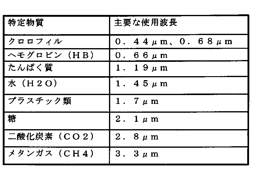
以上、本開示を特定の実施形態に基づいて説明したが、これらの実施形態はあくまでも例示であって、本開示はこれらの実施形態によって限定されるものではない。なお、上記実施形態に示した本開示に係る物質検出装置、物質検出システムおよび物質検出方法の各構成要素は、必ずしも全てが必須ではなく、少なくとも本開示の範囲を逸脱しない限りにおいて適宜取捨選択することが可能である。
本開示は、検出領域内において容易に物質を検出できる物質検出装置、物質検出システム及び物質検出方法等に有用である。また、本開示は、検出領域内における物質の検出精度を向上できる物質検出装置及び物質検出方法等に有用である。また、本開示は、ユーザの多大な労力を要することなく、検知領域内において、可視光の撮像では視認が困難な物質を細かい分解能でかつ容易に検知する物質検出装置、物質検出システム及び物質検出方法として有用である。
1,1A,1B 検出カメラ
1w 開口部
1z 筐体
5,5B,5M センサスキャンユニット
10 雲台
11,11A,11B 制御部
12,12A 波長検出温調制御部
14y メモリ
14z テーブル
15 パンチルトユニット
20 プロセッサ
26,26B 信号加工部
27,27A,27B 検出処理部
28 表示処理部
30 温調ユニット
31 I/V変換回路
32 増幅回路
33 フィルタ処理回路
37 表示制御部
38 出力部
112 2次元化ユニット制御部
113 変調信号生成部
114 信号ゲイン調整部
150 モニタ
261 I/V変換回路
262 増幅回路
263 フィルタ処理回路
271 AD変換回路
272 温調制御処理部
273 物質検出処理部
274 距離算出部
AX1,AX2 レンズ回転軸
CEL 参照セル
CLZ,CLZ2,V31 集光レンズ
CS カメラサーバ
D1a,D1b,D2a,D2b 矢印
DS 信号処理部
F1a,F1b,F2a,F2b 力
EP 走査終了位置
FIR NDフィルタ
GS ガス
HM 人物
HP 初期位置
K 検出空間
KL1a,KL1b,KL2a,KL2b コイル
LD1,LD2 レーザダイオード
LS,LS1,LS2,RV,RV1,RV2 レーザ光
Mg1a,Mg1b,Mg1c,Mg1d,Mg2a,Mg2b,Mg2c,Mg2d 磁石
MR1 反射板
NVSS 非可視光センサ
OP1 ガス検知用投射光源光学部
OP2 距離測定用投射光源光学部
PD,PD0,PD2 フォトダイオード
PJ 投射部
PLZ,PLZ1,PLZ2 コリメートレンズ
Pt ペルチェ素子
RM 反射光
RP 受光部
SA 受光処理部
SAR,SARm 検出領域
SP1,SP2,SP11,SP12,SP21,SP22,SP23 照射位置
T1 期間
V20 プロセッサ
V33 イメージセンサ
V35 信号処理部
VSC 可視光カメラ
WAR0,WAR1,WAR2 波長変調範囲
Claims (25)
- 物質の検出領域内及び検出領域外へ第1の非可視光を出射するトランスミッタと、
前記検出領域内において、前記第1の非可視光が前記物質で反射された光である第2の非可視光を受光する第1のレシーバと、
前記第2の非可視光の波長特性に基づいて、前記物質を検出するディテクタと、
前記検出領域内及び前記検出領域外において、前記第1の非可視光の出射方向及び前記第2の非可視光の受光方向を変更するアクチュエータと、
前記検出領域外において検出対象の物質が格納された参照セルと、
前記第1の非可視光が前記参照セルを通過した光である第3の非可視光を受光する第2のレシーバと、
前記第3の非可視光の波長特性に基づいて、前記第1の非可視光の温度を調整して前記第1の非可視光の波長を制御する波長コントローラと、
を備える物質検出装置。 - 請求項1に記載の物質検出装置であって、
前記トランスミッタと前記第1のレシーバとがベースに固定され、
前記トランスミッタは、前記アクチュエータにより前記ベースの向きを変更することで、前記第1の非可視光を用いて、前記検出領域内及び前記検出領域外を走査する、物質検出装置。 - 請求項1または2に記載の物質検出装置であって、更に、
前記検出領域外に配置され、前記第1の非可視光を反射するリフレクタと、
前記第1の非可視光が前記リフレクタで反射された前記第3の非可視光を減衰させるフィルタと、
を備え、
前記第2のレシーバは、減衰した前記第3の非可視光を受光する、物質検出装置。 - 請求項1または2に記載の物質検出装置であって、更に、
前記検出領域外に配置され、前記第1の非可視光を拡散するディフューザを備え、
前記第2のレシーバは、前記第1の非可視光が前記ディフューザにより拡散した前記第3の非可視光を受光する、物質検出装置。 - 請求項1から4のいずれか1項に記載の物質検出装置であって、
前記トランスミッタは、前記アクチュエータの駆動により、前記第1の非可視光を前記検出領域内の各位置へ出射した後、前記検出領域外へ出射する、物質検出装置。 - 請求項1から4のいずれか1項に記載の物質検出装置であって、
前記トランスミッタは、前記アクチュエータの駆動により、前記第1の非可視光を前記検出領域における所定方向に並ぶ各位置へ出射した後、前記検出領域外へ出射する、物質検出装置。 - 請求項3から6のいずれか1項に記載の物質検出装置であって、
前記第1のレシーバは、前記第2のレシーバとして動作し、前記第3の非可視光を受光する、物質検出装置。 - 請求項1から7のいずれか1項に記載の物質検出装置であって、更に、
第1の画像を撮像するイメージセンサを備え、
前記イメージセンサにより画像が撮像される撮像範囲は、前記物質の検出領域を含む、物質検出装置。 - 請求項8に記載の物質検出装置であって、更に、
検出された前記物質の前記検出領域内の位置を可視化し、可視化された情報を前記第1の画像に重畳して第2の画像を生成するプロセッサと、
前記第2の画像を出力するアウトプットデバイスと、
を備える、物質検出装置。 - 物質の検出領域内へ第1の非可視光を波長変調して出射するトランスミッタと、
前記検出領域内において、前記第1の非可視光が物質で反射された光である第2の非可視光を受光するレシーバと、
前記第2の非可視光の波長特性に基づいて、前記物質を検出するディテクタと、
前記検出領域内において、前記第1の非可視光の出射方向及び前記第2の非可視光の受光方向を変更するアクチュエータと、
前記第1の非可視光の波長変調の周波数である変調周波数と、前記ディテクタにより前記物質を検出するための前記変調周波数に対応する検出周波数と、を変更するコントローラと、
を備える物質検出装置。 - 請求項10に記載の物質検出装置であって、
前記トランスミッタは、前記検出領域において複数回、前記第1の非可視光を出射し、
前記第1のレシーバは、前記検出領域において複数回、前記第2の非可視光を受光し、
前記ディテクタは、前記検出領域において複数回、前記物質を検出するための検出動作を反復し、
前記コントローラは、前記検出領域全体での1回の検出動作毎、前記検出領域における所定方向に沿うラインでの検出動作毎、又は前記検出領域における単位領域毎に、前記変調周波数及び前記検出周波数を変更する、物質検出装置。 - 請求項11に記載の物質検出装置であって、
前記ディテクタは、前記検出領域における任意の領域において、第1の検出周波数を用いた前記物質の検出と、第2の検出周波数を用いた前記物質の検出と、を反復して行う、物質検出装置。 - 請求項12に記載の物質検出装置であって、
前記ディテクタは、同一の単位領域において、前記第1の検出周波数を用いた前記物質の検出と、前記第2の検出周波数を用いた前記物質の検出と、を前記1回の検出動作で行う、物質検出装置。 - 請求項12に記載の物質検出装置であって、
前記ディテクタは、前記検出領域における任意の領域において、前記第1の検出周波数を用いた前記物質の検出結果と前記第2の検出周波数を用いた前記物質の検出結果とが異なる場合、前記任意の領域に前記物質が存在しないと判定する、物質検出装置。 - 物質の検知用波長を有する第1の光を検知エリアに出射する第1の光源と、
距離の測定用波長を有する第2の光を前記検知エリアに出射する第2の光源と、
前記第2の光が前記検知エリア内の照射位置で反射した前記第2の光の反射光を基に、前記照射位置までの距離を測定する距離測定部と、
前記距離測定部の測定結果に応じて、前記第1の光の出力ゲインを調整するゲイン調整部と、
前記ゲイン調整部により前記出力ゲインが調整された前記第1の光が前記照射位置で反射された前記第1の光の反射光を基に、前記検知エリア内における前記物質の有無を検知する物質検出部と、を備え、
前記検知エリア内における前記第1の光及び前記第2の光の走査において、前記第2の光が照射される照射位置は、前記第1の光が照射される照射位置より時間的に先行して照射される、
物質検出装置。 - 請求項15に記載の物質検出装置であって、
前記検知エリアに対する前記第1の光の出射と前記第2の光の出射とが所定の方向に沿って走査される際、前記第1の光源は、直前の前記第2の光の照射位置に前記第1の光を照射するように前記第1の光を出射する、
物質検出装置。 - 請求項16に記載の物質検出装置であって、
前記第1の光源と前記第2の光源とがベースに固定され、
前記第1の光源及び前記第2の光源は、前記ベースの旋回に応じて、前記第1の光の出射及び前記第2の光の出射を前記所定の方向に沿って走査する、
物質検出装置。 - 請求項17に記載の物質検出装置であって、
前記第1の光源及び前記第2の光源は、前記第1の光の照射位置と前記第2の光の照射位置とが前記検知エリア内で1照射位置分ずれて照射されるように、前記ベースに固定される、
物質検出装置。 - 請求項16に記載の物質検出装置であって、
前記検知エリアに対する前記第1の光の出射と前記第2の光の出射とが前記所定の方向に沿って往復して走査される際、往路方向と復路方向とのいずれの走査方向においても、前記第2の光の照射位置が1照射位置の分、前記第1の光の照射位置より先行するように、前記走査方向の切り替え時に、前記第1の光の照射方向と前記第2の光の照射方向とを交差させる照射制御部、を更に備える、
物質検出装置。 - 請求項15に記載の物質検出装置であって、
前記物質検出部により検知された前記物質の画像データを生成する画像生成部と、
前記画像生成部により生成された前記物質の画像データを出力する画像出力部と、を更に備える、
物質検出装置。 - 請求項9に記載の物質検出装置と、
前記物質検出装置により出力された前記第2の画像を表示するモニタと、
を備える物質検出システム。 - 請求項20に記載の物質検出装置と、
前記検知エリアの可視光画像を撮像する撮像装置と、
前記撮像装置により撮像された前記可視光画像のデータに、前記画像出力部により出力された前記物質の画像データを重畳して表示するモニタ装置と、を備える、
物質検出システム。 - 物質検出装置における物質検出方法であって、
物質の検出領域内及び検出領域外へ、第1の非可視光の出射方向を変更して、前記第1の非可視光を出射し、
前記検出領域内において、前記第1の非可視光が前記物質で反射された光である第2の非可視光の受光方向を変更して、前記第2の非可視光を受光し、
前記第2の非可視光の波長特性に基づいて、前記物質を検出し、
前記検出領域外において検出対象の物質が格納された参照セルを、前記第1の非可視光が通過した光である第3の非可視光を受光し、
前記第3の非可視光の波長特性に基づいて、前記第1の非可視光の温度を調整して前記第1の非可視光の波長を制御する、物質検出方法。 - 請求項23に記載の物質検出方法であって、更に、
物質の検出領域内において、第1の非可視光の出射方向及び前記第1の非可視光が前記物質で反射された光である第2の非可視光の受光方向を変更し、
前記第1の非可視光の波長変調の周波数である変調周波数と、前記物質を検出するための前記変調周波数に対応する検出周波数と、を変更し、
前記検出領域内へ前記第1の非可視光を波長変調して出射し、
前記検出領域内において、前記第1の非可視光が物質で反射された光である第2の非可視光を受光し、
前記第2の非可視光の波長特性に基づいて、前記物質を検出する、物質検出方法。 - 請求項23に記載の物質検出方法であって、更に、
第1の光源及び第2の光源を少なくとも有する物質検出装置における物質検出方法であって、
前記第2の光源から、距離の測定用波長を有する測定光を検知エリアに出射し、
前記測定光が前記検知エリア内の照射位置で反射した前記測定光の反射光を基に、前記照射位置までの距離を測定し、
前記測定により得られた前記照射位置までの距離に応じて、物質の検知用波長を有する検知光の出力ゲインを調整し、
前記第1の光源から、前記出力ゲインが調整された前記検知光を前記検知エリアに出射し、
前記出力ゲインが調整された前記検知光が前記照射位置で反射された前記検知光の反射光を基に、前記検知エリア内における前記物質の有無を検知し、
前記検知エリア内における前記検知光及び前記測定光の走査において、前記検知光が照射される照射位置は、前記測定光が照射される照射位置より時間的に先行して照射される、
物質検出方法。
Priority Applications (2)
| Application Number | Priority Date | Filing Date | Title |
|---|---|---|---|
| US15/751,353 US10585037B2 (en) | 2015-08-24 | 2016-08-08 | Substance detecting device, substance detecting system, and substance detecting method in which temperature control of light emission is performed |
| EP16838770.2A EP3343202B1 (en) | 2015-08-24 | 2016-08-08 | Substance detecting device, substance detecting system, and substance detecting method |
Applications Claiming Priority (6)
| Application Number | Priority Date | Filing Date | Title |
|---|---|---|---|
| JP2015165082A JP2017044495A (ja) | 2015-08-24 | 2015-08-24 | 物質検知装置、物質検知システム及び物質検知方法 |
| JP2015-165082 | 2015-08-24 | ||
| JP2015-191960 | 2015-09-29 | ||
| JP2015191960A JP6660582B2 (ja) | 2015-09-29 | 2015-09-29 | 物質検出装置及び物質検出システム |
| JP2015-211280 | 2015-10-27 | ||
| JP2015211280A JP6660583B2 (ja) | 2015-10-27 | 2015-10-27 | 物質検出装置及び物質検出方法 |
Publications (1)
| Publication Number | Publication Date |
|---|---|
| WO2017033419A1 true WO2017033419A1 (ja) | 2017-03-02 |
Family
ID=58099722
Family Applications (1)
| Application Number | Title | Priority Date | Filing Date |
|---|---|---|---|
| PCT/JP2016/003636 WO2017033419A1 (ja) | 2015-08-24 | 2016-08-08 | 物質検出装置、物質検出システム及び物質検出方法 |
Country Status (3)
| Country | Link |
|---|---|
| US (1) | US10585037B2 (ja) |
| EP (1) | EP3343202B1 (ja) |
| WO (1) | WO2017033419A1 (ja) |
Cited By (11)
| Publication number | Priority date | Publication date | Assignee | Title |
|---|---|---|---|---|
| WO2019049562A1 (ja) * | 2017-09-11 | 2019-03-14 | パナソニックIpマネジメント株式会社 | 物質検知装置及び物質検知方法 |
| WO2019134844A1 (de) * | 2018-01-08 | 2019-07-11 | Robert Bosch Gmbh | Optisches sensormodul für spektroskopische messung |
| USRE48490E1 (en) | 2006-07-13 | 2021-03-30 | Velodyne Lidar Usa, Inc. | High definition LiDAR system |
| US10983218B2 (en) | 2016-06-01 | 2021-04-20 | Velodyne Lidar Usa, Inc. | Multiple pixel scanning LIDAR |
| US11073617B2 (en) | 2016-03-19 | 2021-07-27 | Velodyne Lidar Usa, Inc. | Integrated illumination and detection for LIDAR based 3-D imaging |
| US11082010B2 (en) | 2018-11-06 | 2021-08-03 | Velodyne Lidar Usa, Inc. | Systems and methods for TIA base current detection and compensation |
| US11137480B2 (en) | 2016-01-31 | 2021-10-05 | Velodyne Lidar Usa, Inc. | Multiple pulse, LIDAR based 3-D imaging |
| US11703569B2 (en) | 2017-05-08 | 2023-07-18 | Velodyne Lidar Usa, Inc. | LIDAR data acquisition and control |
| US11808891B2 (en) | 2017-03-31 | 2023-11-07 | Velodyne Lidar Usa, Inc. | Integrated LIDAR illumination power control |
| US11885958B2 (en) | 2019-01-07 | 2024-01-30 | Velodyne Lidar Usa, Inc. | Systems and methods for a dual axis resonant scanning mirror |
| US11933967B2 (en) | 2019-08-22 | 2024-03-19 | Red Creamery, LLC | Distally actuated scanning mirror |
Families Citing this family (3)
| Publication number | Priority date | Publication date | Assignee | Title |
|---|---|---|---|---|
| JP6508439B2 (ja) * | 2016-12-27 | 2019-05-08 | コニカミノルタ株式会社 | ガス検知用画像処理装置、ガス検知用画像処理方法及びガス検知用画像処理プログラム |
| US10739196B2 (en) * | 2018-07-03 | 2020-08-11 | Electronics And Telecommunications Research Institute | Spectroscopic apparatus and spectroscopic method using orthogonal code |
| CN112188055A (zh) * | 2020-09-28 | 2021-01-05 | 维沃移动通信有限公司 | 摄像头模组、识别方法、电子设备及可读存储介质 |
Citations (7)
| Publication number | Priority date | Publication date | Assignee | Title |
|---|---|---|---|---|
| JP2002196075A (ja) * | 2000-12-26 | 2002-07-10 | Inc Engineering Co Ltd | レーザレーダ監視方法及び装置 |
| JP2003315267A (ja) * | 2002-04-24 | 2003-11-06 | Nippon Steel Corp | 粉じん監視方法 |
| JP2005077279A (ja) * | 2003-09-01 | 2005-03-24 | Mitsubishi Electric Corp | 煙感知システム |
| JP2012000147A (ja) * | 2010-06-14 | 2012-01-05 | Sony Corp | 画像処理装置、画像処理方法、プログラム、及び電子装置 |
| JP2013128185A (ja) * | 2011-12-16 | 2013-06-27 | Toshiba Corp | カメラシステム、およびカメラマウント |
| JP2014119323A (ja) * | 2012-12-14 | 2014-06-30 | Mitsubishi Heavy Ind Ltd | ガス漏洩検知システム |
| JP2014235103A (ja) * | 2013-06-03 | 2014-12-15 | 日本電信電話株式会社 | 光吸収測定用レーザ光源およびそれを用いた光吸収測定装置 |
Family Cites Families (11)
| Publication number | Priority date | Publication date | Assignee | Title |
|---|---|---|---|---|
| JP3229391B2 (ja) | 1992-11-05 | 2001-11-19 | 東京電力株式会社 | 光ファイバを用いた多点ガス濃度測定方法及び装置 |
| JP3051808B2 (ja) | 1993-11-30 | 2000-06-12 | アンリツ株式会社 | ガス濃度測定装置 |
| JP2005106521A (ja) | 2003-09-29 | 2005-04-21 | Anritsu Corp | 半導体レーザユニット及びガス濃度測定装置 |
| DE602005003337T2 (de) | 2004-03-09 | 2008-09-04 | Senscient Ltd., Sandford | Gasnachweis |
| JP2007240248A (ja) | 2006-03-07 | 2007-09-20 | Hitachi Cable Ltd | 光式多ガス濃度検出方法及び装置 |
| CA2674528C (en) * | 2006-12-22 | 2016-02-09 | Photonic Innovations Limited | Gas detector |
| JP2008232920A (ja) * | 2007-03-22 | 2008-10-02 | Anritsu Corp | ガス検知装置及び該装置を用いた校正方法並びに波長確認方法 |
| US7969576B1 (en) * | 2007-03-23 | 2011-06-28 | The Regents Of The University Of California | Optical sensing based on wavelength modulation spectroscopy |
| US8395777B2 (en) * | 2010-09-09 | 2013-03-12 | Adelphi University | Method and apparatus for trace gas detection using integrated wavelength modulated spectra across multiple lines |
| US8896835B2 (en) * | 2011-12-27 | 2014-11-25 | Horiba, Ltd. | Gas measurement apparatus and the setting method of width of wavelength modulation in gas measurement apparatus |
| US9297756B2 (en) * | 2013-02-01 | 2016-03-29 | Battelle Memorial Institute | Capillary absorption spectrometer and process for isotopic analysis of small samples |
-
2016
- 2016-08-08 EP EP16838770.2A patent/EP3343202B1/en active Active
- 2016-08-08 WO PCT/JP2016/003636 patent/WO2017033419A1/ja active Application Filing
- 2016-08-08 US US15/751,353 patent/US10585037B2/en active Active
Patent Citations (7)
| Publication number | Priority date | Publication date | Assignee | Title |
|---|---|---|---|---|
| JP2002196075A (ja) * | 2000-12-26 | 2002-07-10 | Inc Engineering Co Ltd | レーザレーダ監視方法及び装置 |
| JP2003315267A (ja) * | 2002-04-24 | 2003-11-06 | Nippon Steel Corp | 粉じん監視方法 |
| JP2005077279A (ja) * | 2003-09-01 | 2005-03-24 | Mitsubishi Electric Corp | 煙感知システム |
| JP2012000147A (ja) * | 2010-06-14 | 2012-01-05 | Sony Corp | 画像処理装置、画像処理方法、プログラム、及び電子装置 |
| JP2013128185A (ja) * | 2011-12-16 | 2013-06-27 | Toshiba Corp | カメラシステム、およびカメラマウント |
| JP2014119323A (ja) * | 2012-12-14 | 2014-06-30 | Mitsubishi Heavy Ind Ltd | ガス漏洩検知システム |
| JP2014235103A (ja) * | 2013-06-03 | 2014-12-15 | 日本電信電話株式会社 | 光吸収測定用レーザ光源およびそれを用いた光吸収測定装置 |
Cited By (23)
| Publication number | Priority date | Publication date | Assignee | Title |
|---|---|---|---|---|
| USRE48666E1 (en) | 2006-07-13 | 2021-08-03 | Velodyne Lidar Usa, Inc. | High definition LiDAR system |
| USRE48504E1 (en) | 2006-07-13 | 2021-04-06 | Velodyne Lidar Usa, Inc. | High definition LiDAR system |
| USRE48688E1 (en) | 2006-07-13 | 2021-08-17 | Velodyne Lidar Usa, Inc. | High definition LiDAR system |
| USRE48503E1 (en) | 2006-07-13 | 2021-04-06 | Velodyne Lidar Usa, Inc. | High definition LiDAR system |
| USRE48490E1 (en) | 2006-07-13 | 2021-03-30 | Velodyne Lidar Usa, Inc. | High definition LiDAR system |
| USRE48491E1 (en) | 2006-07-13 | 2021-03-30 | Velodyne Lidar Usa, Inc. | High definition lidar system |
| US11698443B2 (en) | 2016-01-31 | 2023-07-11 | Velodyne Lidar Usa, Inc. | Multiple pulse, lidar based 3-D imaging |
| US11137480B2 (en) | 2016-01-31 | 2021-10-05 | Velodyne Lidar Usa, Inc. | Multiple pulse, LIDAR based 3-D imaging |
| US11073617B2 (en) | 2016-03-19 | 2021-07-27 | Velodyne Lidar Usa, Inc. | Integrated illumination and detection for LIDAR based 3-D imaging |
| US11808854B2 (en) | 2016-06-01 | 2023-11-07 | Velodyne Lidar Usa, Inc. | Multiple pixel scanning LIDAR |
| US11874377B2 (en) | 2016-06-01 | 2024-01-16 | Velodyne Lidar Usa, Inc. | Multiple pixel scanning LIDAR |
| US10983218B2 (en) | 2016-06-01 | 2021-04-20 | Velodyne Lidar Usa, Inc. | Multiple pixel scanning LIDAR |
| US11550056B2 (en) | 2016-06-01 | 2023-01-10 | Velodyne Lidar Usa, Inc. | Multiple pixel scanning lidar |
| US11561305B2 (en) | 2016-06-01 | 2023-01-24 | Velodyne Lidar Usa, Inc. | Multiple pixel scanning LIDAR |
| US11808891B2 (en) | 2017-03-31 | 2023-11-07 | Velodyne Lidar Usa, Inc. | Integrated LIDAR illumination power control |
| US11703569B2 (en) | 2017-05-08 | 2023-07-18 | Velodyne Lidar Usa, Inc. | LIDAR data acquisition and control |
| JP2019049496A (ja) * | 2017-09-11 | 2019-03-28 | パナソニックIpマネジメント株式会社 | 物質検知装置及び物質検知方法 |
| WO2019049562A1 (ja) * | 2017-09-11 | 2019-03-14 | パナソニックIpマネジメント株式会社 | 物質検知装置及び物質検知方法 |
| WO2019134844A1 (de) * | 2018-01-08 | 2019-07-11 | Robert Bosch Gmbh | Optisches sensormodul für spektroskopische messung |
| CN111587364A (zh) * | 2018-01-08 | 2020-08-25 | 罗伯特·博世有限公司 | 用于光谱测量的光学传感器模块 |
| US11082010B2 (en) | 2018-11-06 | 2021-08-03 | Velodyne Lidar Usa, Inc. | Systems and methods for TIA base current detection and compensation |
| US11885958B2 (en) | 2019-01-07 | 2024-01-30 | Velodyne Lidar Usa, Inc. | Systems and methods for a dual axis resonant scanning mirror |
| US11933967B2 (en) | 2019-08-22 | 2024-03-19 | Red Creamery, LLC | Distally actuated scanning mirror |
Also Published As
| Publication number | Publication date |
|---|---|
| US20180231460A1 (en) | 2018-08-16 |
| EP3343202A1 (en) | 2018-07-04 |
| EP3343202B1 (en) | 2019-12-04 |
| US10585037B2 (en) | 2020-03-10 |
| EP3343202A4 (en) | 2018-12-12 |
Similar Documents
| Publication | Publication Date | Title |
|---|---|---|
| WO2017033419A1 (ja) | 物質検出装置、物質検出システム及び物質検出方法 | |
| US8786858B2 (en) | Gas detector | |
| EP1030163B1 (en) | reflective prism device | |
| JP5281923B2 (ja) | 投射型表示装置 | |
| WO2009031094A1 (en) | Laser scanning projection device with eye detection unit | |
| JP2014032149A (ja) | 物体検出装置 | |
| CA2590216A1 (en) | Optical gas detection | |
| JP2008020204A (ja) | レーダ | |
| EP2784458A1 (en) | Projector, head-up display device, and control method of projector | |
| KR20220043907A (ko) | 양자기반 가스 감지장치 및 방법 | |
| JP5079704B2 (ja) | レーザディスプレイ装置 | |
| US7554650B2 (en) | Laser beam projecting device | |
| CN107533220B (zh) | 光扫描控制装置 | |
| WO2012073330A1 (ja) | レーザ光源ユニット及び画像表示装置 | |
| EP1469279B1 (en) | Surveying instrument | |
| JP2019039770A (ja) | 3次元測量装置 | |
| JP6660582B2 (ja) | 物質検出装置及び物質検出システム | |
| JP4549206B2 (ja) | 位置検出装置 | |
| JP4570839B2 (ja) | 光学式座標入力装置及び光学式座標入力方法 | |
| JP6660583B2 (ja) | 物質検出装置及び物質検出方法 | |
| JP2017044495A (ja) | 物質検知装置、物質検知システム及び物質検知方法 | |
| JP2008256497A (ja) | 計測装置 | |
| JP2014059522A (ja) | 画像表示装置 | |
| US20240125938A1 (en) | Optical system for obtaining 3d spatial information | |
| JP2017106754A (ja) | 測定装置 |
Legal Events
| Date | Code | Title | Description |
|---|---|---|---|
| 121 | Ep: the epo has been informed by wipo that ep was designated in this application |
Ref document number: 16838770 Country of ref document: EP Kind code of ref document: A1 |
|
| WWE | Wipo information: entry into national phase |
Ref document number: 15751353 Country of ref document: US |
|
| NENP | Non-entry into the national phase |
Ref country code: DE |
|
| WWE | Wipo information: entry into national phase |
Ref document number: 2016838770 Country of ref document: EP |