WO2019049202A1 - Machine hydraulique - Google Patents
Machine hydraulique Download PDFInfo
- Publication number
- WO2019049202A1 WO2019049202A1 PCT/JP2017/031929 JP2017031929W WO2019049202A1 WO 2019049202 A1 WO2019049202 A1 WO 2019049202A1 JP 2017031929 W JP2017031929 W JP 2017031929W WO 2019049202 A1 WO2019049202 A1 WO 2019049202A1
- Authority
- WO
- WIPO (PCT)
- Prior art keywords
- motor housing
- impeller
- opening
- fluid machine
- coil
- Prior art date
Links
Images


Classifications
-
- F—MECHANICAL ENGINEERING; LIGHTING; HEATING; WEAPONS; BLASTING
- F04—POSITIVE - DISPLACEMENT MACHINES FOR LIQUIDS; PUMPS FOR LIQUIDS OR ELASTIC FLUIDS
- F04D—NON-POSITIVE-DISPLACEMENT PUMPS
- F04D29/00—Details, component parts, or accessories
- F04D29/58—Cooling; Heating; Diminishing heat transfer
- F04D29/5806—Cooling the drive system
-
- F—MECHANICAL ENGINEERING; LIGHTING; HEATING; WEAPONS; BLASTING
- F04—POSITIVE - DISPLACEMENT MACHINES FOR LIQUIDS; PUMPS FOR LIQUIDS OR ELASTIC FLUIDS
- F04D—NON-POSITIVE-DISPLACEMENT PUMPS
- F04D17/00—Radial-flow pumps, e.g. centrifugal pumps; Helico-centrifugal pumps
- F04D17/08—Centrifugal pumps
- F04D17/10—Centrifugal pumps for compressing or evacuating
-
- F—MECHANICAL ENGINEERING; LIGHTING; HEATING; WEAPONS; BLASTING
- F04—POSITIVE - DISPLACEMENT MACHINES FOR LIQUIDS; PUMPS FOR LIQUIDS OR ELASTIC FLUIDS
- F04D—NON-POSITIVE-DISPLACEMENT PUMPS
- F04D17/00—Radial-flow pumps, e.g. centrifugal pumps; Helico-centrifugal pumps
- F04D17/08—Centrifugal pumps
- F04D17/16—Centrifugal pumps for displacing without appreciable compression
-
- F—MECHANICAL ENGINEERING; LIGHTING; HEATING; WEAPONS; BLASTING
- F04—POSITIVE - DISPLACEMENT MACHINES FOR LIQUIDS; PUMPS FOR LIQUIDS OR ELASTIC FLUIDS
- F04D—NON-POSITIVE-DISPLACEMENT PUMPS
- F04D25/00—Pumping installations or systems
- F04D25/02—Units comprising pumps and their driving means
- F04D25/06—Units comprising pumps and their driving means the pump being electrically driven
-
- F—MECHANICAL ENGINEERING; LIGHTING; HEATING; WEAPONS; BLASTING
- F04—POSITIVE - DISPLACEMENT MACHINES FOR LIQUIDS; PUMPS FOR LIQUIDS OR ELASTIC FLUIDS
- F04D—NON-POSITIVE-DISPLACEMENT PUMPS
- F04D25/00—Pumping installations or systems
- F04D25/02—Units comprising pumps and their driving means
- F04D25/08—Units comprising pumps and their driving means the working fluid being air, e.g. for ventilation
- F04D25/082—Units comprising pumps and their driving means the working fluid being air, e.g. for ventilation the unit having provision for cooling the motor
-
- F—MECHANICAL ENGINEERING; LIGHTING; HEATING; WEAPONS; BLASTING
- F04—POSITIVE - DISPLACEMENT MACHINES FOR LIQUIDS; PUMPS FOR LIQUIDS OR ELASTIC FLUIDS
- F04D—NON-POSITIVE-DISPLACEMENT PUMPS
- F04D29/00—Details, component parts, or accessories
- F04D29/05—Shafts or bearings, or assemblies thereof, specially adapted for elastic fluid pumps
- F04D29/053—Shafts
-
- F—MECHANICAL ENGINEERING; LIGHTING; HEATING; WEAPONS; BLASTING
- F04—POSITIVE - DISPLACEMENT MACHINES FOR LIQUIDS; PUMPS FOR LIQUIDS OR ELASTIC FLUIDS
- F04D—NON-POSITIVE-DISPLACEMENT PUMPS
- F04D29/00—Details, component parts, or accessories
- F04D29/08—Sealings
-
- F—MECHANICAL ENGINEERING; LIGHTING; HEATING; WEAPONS; BLASTING
- F04—POSITIVE - DISPLACEMENT MACHINES FOR LIQUIDS; PUMPS FOR LIQUIDS OR ELASTIC FLUIDS
- F04D—NON-POSITIVE-DISPLACEMENT PUMPS
- F04D29/00—Details, component parts, or accessories
- F04D29/26—Rotors specially for elastic fluids
- F04D29/263—Rotors specially for elastic fluids mounting fan or blower rotors on shafts
-
- F—MECHANICAL ENGINEERING; LIGHTING; HEATING; WEAPONS; BLASTING
- F04—POSITIVE - DISPLACEMENT MACHINES FOR LIQUIDS; PUMPS FOR LIQUIDS OR ELASTIC FLUIDS
- F04D—NON-POSITIVE-DISPLACEMENT PUMPS
- F04D29/00—Details, component parts, or accessories
- F04D29/26—Rotors specially for elastic fluids
- F04D29/266—Rotors specially for elastic fluids mounting compressor rotors on shafts
-
- F—MECHANICAL ENGINEERING; LIGHTING; HEATING; WEAPONS; BLASTING
- F04—POSITIVE - DISPLACEMENT MACHINES FOR LIQUIDS; PUMPS FOR LIQUIDS OR ELASTIC FLUIDS
- F04D—NON-POSITIVE-DISPLACEMENT PUMPS
- F04D29/00—Details, component parts, or accessories
- F04D29/26—Rotors specially for elastic fluids
- F04D29/28—Rotors specially for elastic fluids for centrifugal or helico-centrifugal pumps for radial-flow or helico-centrifugal pumps
- F04D29/281—Rotors specially for elastic fluids for centrifugal or helico-centrifugal pumps for radial-flow or helico-centrifugal pumps for fans or blowers
-
- F—MECHANICAL ENGINEERING; LIGHTING; HEATING; WEAPONS; BLASTING
- F04—POSITIVE - DISPLACEMENT MACHINES FOR LIQUIDS; PUMPS FOR LIQUIDS OR ELASTIC FLUIDS
- F04D—NON-POSITIVE-DISPLACEMENT PUMPS
- F04D29/00—Details, component parts, or accessories
- F04D29/40—Casings; Connections of working fluid
- F04D29/42—Casings; Connections of working fluid for radial or helico-centrifugal pumps
- F04D29/4206—Casings; Connections of working fluid for radial or helico-centrifugal pumps especially adapted for elastic fluid pumps
-
- H—ELECTRICITY
- H02—GENERATION; CONVERSION OR DISTRIBUTION OF ELECTRIC POWER
- H02K—DYNAMO-ELECTRIC MACHINES
- H02K9/00—Arrangements for cooling or ventilating
- H02K9/02—Arrangements for cooling or ventilating by ambient air flowing through the machine
- H02K9/04—Arrangements for cooling or ventilating by ambient air flowing through the machine having means for generating a flow of cooling medium
- H02K9/06—Arrangements for cooling or ventilating by ambient air flowing through the machine having means for generating a flow of cooling medium with fans or impellers driven by the machine shaft
-
- F—MECHANICAL ENGINEERING; LIGHTING; HEATING; WEAPONS; BLASTING
- F04—POSITIVE - DISPLACEMENT MACHINES FOR LIQUIDS; PUMPS FOR LIQUIDS OR ELASTIC FLUIDS
- F04D—NON-POSITIVE-DISPLACEMENT PUMPS
- F04D29/00—Details, component parts, or accessories
- F04D29/08—Sealings
- F04D29/10—Shaft sealings
- F04D29/102—Shaft sealings especially adapted for elastic fluid pumps
-
- F—MECHANICAL ENGINEERING; LIGHTING; HEATING; WEAPONS; BLASTING
- F05—INDEXING SCHEMES RELATING TO ENGINES OR PUMPS IN VARIOUS SUBCLASSES OF CLASSES F01-F04
- F05D—INDEXING SCHEME FOR ASPECTS RELATING TO NON-POSITIVE-DISPLACEMENT MACHINES OR ENGINES, GAS-TURBINES OR JET-PROPULSION PLANTS
- F05D2260/00—Function
- F05D2260/20—Heat transfer, e.g. cooling
- F05D2260/221—Improvement of heat transfer
- F05D2260/2214—Improvement of heat transfer by increasing the heat transfer surface
- F05D2260/22141—Improvement of heat transfer by increasing the heat transfer surface using fins or ribs
Definitions
- the present disclosure relates to fluid machines.
- a fluid machine such as a centrifugal fan or compressor may include a motor.
- the motor includes a rotor and a coil surrounding the rotor.
- the rotor of the motor is rotated by the rotating magnetic field generated by the coil.
- An impeller is attached to the rotor, and the fluid machine sucks air as the impeller rotates.
- the coil and the rotor generate heat, and the temperature of the motor may rise.
- the temperature of the motor rises, the rotation efficiency of the motor decreases, and the operation efficiency of the blower and the compressor decreases.
- a main stream or a part of the main stream has been used as cooling air.
- the main stream or a part of the main stream is circulated around the motor to cool the motor in the process of sucking the main stream by rotation of the impeller and exhausting it to the outside.
- the main stream or a part of the main stream when used as the cooling air, the main stream itself needs to have a temperature capable of cooling the motor like outside air or the like. For example, when the temperature of the main stream is high, the main stream or a part of the main stream can not be used as the cooling air.
- the present disclosure describes a fluid machine having a structure that sucks outside air as cooling air separately from the main flow.
- a fluid machine includes a motor housing including a first end and a second end in an axial direction, and a protrusion inserted through the motor housing and protruding from the first end or the second end of the motor housing.
- a rotary shaft including the impeller, an impeller attached to the protrusion of the rotary shaft, a facing portion facing the motor housing at a first end in the axial direction, and a first opening provided at the first end of the motor housing;
- a second opening provided on the second end side of the motor housing and communicating with the outside air, an in-housing flow passage formed in the motor housing and communicating the first opening and the second opening, a motor housing and a facing portion
- An exhaust flow path communicating between the first opening and the outside air, and a swirl vane disposed between the first opening and the exhaust flow path, attached to the rotation shaft and rotatable with the rotation shaft And.
- outside air is drawn into the motor housing as cooling air separately from the main flow.
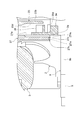
- FIG. 1 is a cross-sectional view showing a fluid machine according to an embodiment of the present disclosure.
- FIG. 2 is a view of the motor housing in FIG. 1 as viewed from the second end side in the axial direction.
- 3 (A) is a front view showing the flow path forming plate in FIG. 1
- FIG. 3 (B) is a cross-sectional view taken along the line IIIB-IIIB in FIG. 3 (A)
- FIG. It is a principal part enlarged view of FIG. 3 (B).
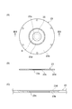
- FIG. 4 (A) is a front view showing the cooling fan in FIG. 1
- FIG. 4 (B) is a cross-sectional view taken along the line IVB-IVB in FIG. 4 (A).
- FIG. 5 is a cross-sectional view showing a seal formed around the boss of the impeller in FIG.
- a fluid machine includes a motor housing including a first end and a second end in an axial direction, and a protrusion inserted through the motor housing and protruding from the first end or the second end of the motor housing.
- a rotary shaft including the impeller, an impeller attached to the protrusion of the rotary shaft, a facing portion facing the motor housing at a first end in the axial direction, and a first opening provided at the first end of the motor housing;
- a second opening provided on the second end side of the motor housing and communicating with the outside air, an in-housing flow passage formed in the motor housing and communicating the first opening and the second opening, a motor housing and a facing portion
- An exhaust flow path communicating between the first opening and the outside air, and a swirl vane disposed between the first opening and the exhaust flow path, attached to the rotation shaft and rotatable with the rotation shaft And.
- the second opening, the flow passage in the housing, the first opening, and the exhaust flow passage communicate with each other.
- the swirl vanes rotate with the rotation shaft
- the outside air is drawn from the second opening and flows through the plurality of spaces described above.
- the motor can be cooled by the ambient air flowing in the motor housing.
- outside air is drawn into the motor housing as cooling air separately from the main flow.
- the impeller is attached to a protrusion that projects from the first end of the motor housing, the facing portion is disposed between the first end of the motor housing and the impeller, and a portion of the back of the impeller is It is located on the motor housing side of the facing part.
- the facing portion defines the main flow path generated by the impeller and the flow path of the cooling air flowing in the motor housing. Since a part of the back surface of the impeller is located on the motor housing side of the facing portion, axial compactification is achieved.
- a coil is fixed to the inner circumferential surface of the motor housing, and the motor housing includes a groove formed on the inner circumferential surface and extending in the axial direction over the area provided with the coil.
- the cooling air can easily flow in the motor housing through the groove. The cooling air tends to cool the coil.
- the coil is axially spaced apart from the first end and the second end of the motor housing. In this case, the outside air is easily introduced into the groove in the motor housing. As a result, the cooling efficiency of the coil is improved.
- the fluid machine further comprises a cooling fan formed with pivoting vanes, the cooling fan including a boss through which the rotation shaft is inserted, and the impeller projecting from the first end of the motor housing
- the rotating shaft includes a stepped portion opposed to the back surface of the impeller, and the cooling fan is attached to the rotating shaft by holding the boss between the impeller and the stepped portion of the rotating shaft.
- the cooling fan can be attached to the rotating shaft using the impeller and the step portion provided on the rotating shaft.
- the impeller is screwed into a projection that projects from the first end of the motor housing and presses the cooling fan boss at the back of the impeller.
- the cooling fan can be securely and easily attached to the rotating shaft by screwing the impeller to the rotating shaft.
- the swirl vane includes an inner end, which is an end closer to the rotation axis, and an outer end, which is an end farther from the rotation axis, and extends between the inner end and the outer end.
- the outer end is located upstream of the inner end in the rotational direction of the rotation axis.
- the first opening is located inside the outer end which is the end farther from the rotational axis of the pivoting vanes. In this case, the suction efficiency of the cooling air from within the motor housing by the swirl vanes is improved.
- the fluid machine includes a seal formed on the inner diameter side of the facing portion to seal the motor housing and the impeller.
- FIG. 1 A fluid machine according to an embodiment of the present disclosure will be described with reference to FIG.
- the left side with respect to the paper surface is the tip (first end) side
- the right side with respect to the paper surface is the proximal end (second end) side.
- distal side and proximal side are used with reference to the axial direction.
- a centrifugal fan 1 will be described as an example of a fluid machine.
- the centrifugal blower 1 is, for example, an air-cooled electric blower that sucks in air and delivers it at a predetermined pressure.
- the centrifugal blower 1 is provided with an air inlet on the tip side.
- the centrifugal blower 1 includes an impeller housing 3 in which the impeller 2 is housed, and a motor housing 5 in which a coil 4 which is a rotational drive unit for rotating the impeller 2 is housed.
- the motor housing 5 includes a cylindrical motor housing body 6.
- a radiation fin 7 is formed on the outer peripheral surface of the motor housing main body 6.
- the motor housing main body 6 includes a first end 5a on the distal end side in the axial direction and a second end 5b on the proximal end side.
- the motor housing body 6 includes an insertion hole 6a extending in the axial direction between the first end 5a and the second end 5b.
- a rotating shaft 8 made of, for example, stainless steel is inserted into the motor housing main body 6.
- the rotary shaft 8 is provided in the motor housing main body 6 at a first bearing 18 provided near the first end 5a, and in the motor housing main body 6 near the second end 5b. It is supported by the second bearing portion 11.
- the rotation axis 8 is rotatable about its rotation axis X.
- the rotary shaft 8 has a first end 8 b axially projecting from the first end 5 a of the motor housing main body 6 and a second end 8 c axially projecting from the second end 5 b of the motor housing main body 6. including.
- An impeller 2 made of, for example, aluminum is attached to a first end 8 b which is a projecting portion of the rotating shaft 8. More specifically, a through hole is formed in the impeller 2 along the rotation axis X, and the first end 8 b of the rotation shaft 8 is inserted through the through hole.
- an external thread is formed on the circumferential surface of the first end 8 b.
- a boss portion 2 a that protrudes in the back direction is formed.
- the motor housing main body 6 includes a first opening formed on the distal end side of the insertion hole 6a and a second opening formed on the proximal end side of the insertion hole 6a.
- the insertion hole 6a includes a first cylindrical portion 6b extending from the first opening to the proximal end, an annular first step 6c having a diameter reduced from the first cylindrical portion 6b, and a base end from the first step 6c.
- a second cylindrical portion 6d extending to the side, an annular second stepped portion 6e reduced in diameter from the second cylindrical portion 6d, a third cylindrical portion 6f extending to the base end side from the second stepped portion 6e, and And an annular third step portion 6g expanding in diameter from the third cylindrical portion 6f, and a fourth cylindrical portion 6h extending from the third step portion 6g to the second opening.
- the diameter of the first cylindrical portion 6b is larger than the diameter of the second cylindrical portion 6d.
- the diameter of the second cylindrical portion 6d and the diameter of the fourth cylindrical portion 6h are respectively larger than the diameter of the third cylindrical portion 6f.
- the third cylindrical portion 6 f is, for example, a portion having the smallest diameter in the insertion hole 6 a of the motor housing main body 6.
- a rotor 8 a is fixed to the axial center of the rotation shaft 8.
- the outer diameter of the rotor 8 a is larger than the diameter of the other portion of the rotating shaft 8.
- the rotor 8a includes a generation source of a magnetic field such as a permanent magnet.
- the rotor 8 a is accommodated in the motor housing main body 6. That is, both axial ends of the rotor 8 a are located between the first end 5 a and the second end 5 b of the motor housing body 6.
- Coil 4 is, for example, an electromagnetic coil.
- the coil 4 is fixed to the third cylindrical portion 6 f (inner peripheral surface) of the motor housing main body 6.
- the coil 4 may include, for example, a conductive wire and a stator core which is an iron core wound with the conductive wire (all not shown).
- the coil 4 is disposed around the rotor 8a and faces the rotor 8a with a gap.
- the motor 10 of the present embodiment is configured by the stator including the coil 4 and the rotor 8 a.
- the coil 4 can be energized via a wire not shown. By energizing the coil 4, a rotating magnetic field is generated between the coil 4 and the rotor 8a, and the rotor 8a rotates.
- the coil 4 is axially separated from the first end 5 a and the second end 5 b of the motor housing 5.
- the coil 4 is shorter than the length between the first end 5a and the second end 5b in the axial direction.
- the coil 4 is shorter than, for example, the length of the third cylindrical portion 6f in the axial direction.
- the coil 4 is housed in the third cylindrical portion 6f.
- One or more grooves 9 are provided in the motor housing body 6.
- the direction in which the groove 9 extends is divided into an axial component and a circumferential component
- the direction in which the groove 9 extends includes at least an axial component.
- the groove 9 is formed, for example, in the third cylindrical portion 6f, and is connected to the second step 6e and the third step 6g.
- the bottom of the groove 9 (the part farthest from the rotation axis X) is radially spaced from the coil 4 provided in the third cylindrical part.
- the groove 9 defines an axially extending space on the outer peripheral side of the coil 4.
- a plurality of grooves 9 are formed.
- the plurality of grooves 9 are formed, for example, with a predetermined angular pitch.
- six grooves 9 are formed at an angular pitch of 60 °.
- the plurality of grooves 9 extend axially and may be parallel to one another.
- the groove or grooves 9 may extend helically about the rotation axis X.
- the groove 9 extends in the axial direction over the area in which the coil 4 is provided. In other words, the groove 9 is longer than the length of the coil 4 in the axial direction.
- a portion of the rotary shaft 8 located on the tip end side of the rotor 8 a is supported by the first bearing portion 18.
- a portion of the rotary shaft 8 located on the proximal side of the rotor 8 a is supported by the second bearing portion 11. That is, the rotating shaft 8 is rotatably supported by the first bearing portion 18 and the second bearing portion 11.
- the first bearing portion 18 is a cylindrical support portion 18 b that faces the rotation shaft 8 to support the rotation shaft 8, and a flange that is provided at a base end portion in the axial direction of the support portion 18 b and protrudes radially outward. And a unit 18a.
- the second bearing portion 11 is a cylindrical support portion 11 b facing the rotation shaft 8 to support the rotation shaft 8, and a flange portion provided at the tip end portion in the axial direction of the support portion 11 b and protruding radially outward And 11a.
- a first bearing plate 19 is fitted to the second cylindrical portion 6 d of the motor housing main body 6.
- the first bearing plate 19 is an annular member that is fitted on the first end 5 a side of the motor housing main body 6 and holds the first bearing 18.
- the second bearing plate 12 is fitted to the fourth cylindrical portion 6 h of the motor housing main body 6.
- the second bearing plate 12 is an annular member that is fitted on the second end 5 b side of the motor housing main body 6 and holds the second bearing portion 11.
- the second bearing plate 12 will be described with reference to FIGS. 1 and 2.
- the first bearing plate 19 may have the same structure as the second bearing plate 12.
- the first bearing plate 19 and the first bearing portion 18 have, for example, a plane-symmetrical structure with the second bearing plate 12 and the second bearing portion 11 with respect to a plane perpendicular to the rotation axis X.
- the second bearing plate 12 will be described, and a detailed description of the first bearing plate 19 will be omitted.
- the second bearing plate 12 has a cylindrical rim portion 12 a fitted to the fourth cylindrical portion 6 h of the motor housing main body 6 and a cylindrical shape to which the second bearing portion 11 is fixed. It includes a hub portion 12c and a plurality of spoke portions 12b connecting the rim portion 12a and the hub portion 12c.
- the hub portion 12c is provided with an insertion hole 12d penetrating in the axial direction. The rotary shaft 8 supported by the support portion 11 b and the support portion 11 b is inserted into the insertion hole 12 d.
- the rim portion 12 a of the second bearing plate 12 is fitted into the fourth cylindrical portion 6 h of the motor housing main body 6 and is fixed to the third step portion 6 g by a bolt or the like.
- the flange portion 11 a of the second bearing portion 11 is fixed to the hub portion 12 c of the second bearing plate 12 by a bolt or the like.
- the second bearing portion 11 is fixed to the hub portion 12c.
- the second bearing plate 12 restrains axial and radial displacements of the second bearing portion 11.
- a plurality of intake ports (second openings) 14 penetrating in the axial direction are provided on the outer peripheral side of the hub portion 12c of the second bearing plate 12.
- the intake ports 14 communicate with a space on the second end 5 b side of the motor housing main body 6 and an opening on the proximal end side of the third cylindrical portion 6 f.
- An area not blocked by the spokes 12 b between the rim 12 a and the hub 12 c is an air inlet 14.
- the intake port 14 is provided on the side of the second end 5 b of the motor housing 5 and communicates with the outside air, and communicates with the insertion hole 6 a of the motor housing main body 6.
- a plurality of intake ports 14 are formed in the second bearing plate 12 at a predetermined angular pitch.
- the air intake port 14 may be provided with a filter (not shown) such as a dustproof filter.
- the first bearing plate 19 also includes a rim portion, a hub portion, and a plurality of spoke portions.
- the rim portion of the first bearing plate 19 is fitted into the second cylindrical portion 6 d of the motor housing main body 6 and is fixed to the second step portion 6 e.
- the flange portion 18 a of the first bearing portion 18 is fixed to the hub portion of the first bearing plate 19.
- the first bearing plate 19 restrains axial and radial displacements of the first bearing portion 18.
- a plurality of openings 20 are formed on the outer peripheral side of the hub portion, for example, at a predetermined angular pitch.
- the opening 20 communicates with the opening on the tip end side of the third cylindrical portion 6 f. That is, the opening 20 communicates with the insertion hole 6 a of the motor housing main body 6.
- the flow path forming plate 23 provided at the first end 5a of the motor housing 5 will be described.
- an annular flow path forming plate 23 is fitted in the first cylindrical portion 6b of the motor housing main body 6.
- the flow path forming plate 23 includes an annular outer peripheral plate portion 23a fitted to the first cylindrical portion 6b, and an inner peripheral plate portion 23b continuous to the inner side of the outer peripheral plate portion 23a.
- a circular flow passage forming hole 23c penetrating in the axial direction is formed.
- the inner peripheral plate portion 23b is thinner than the outer peripheral plate portion 23a in the axial direction. More specifically, the outer peripheral plate portion 23a has a constant thickness.
- the inner circumferential plate portion 23b is inclined from the inner circumferential end of the outer circumferential plate portion 23a toward the flow passage forming hole 23c, and becomes thinner toward the flow passage forming hole 23c.
- the back surface facing the insertion hole 6a of the flow channel forming plate 23 (facing the coil 4) is flat, the surface of the flow channel forming plate 23 which is the opposite side has a hollow portion 23d (see FIG. And FIG. 3 (C)).
- the flow path forming plate 23 may protrude from the first opening on the tip end side of the motor housing main body 6. That is, a part of the flow path forming plate 23 in the thickness direction (axial direction) may be fitted to the first cylindrical portion 6 b.
- the flow path forming plate 23 is axially separated from the first bearing plate 19.
- the flow path forming plate 23 is also separated from the first bearing portion 18 attached to the first bearing plate 19. That is, a space 24 extending in the radial direction is formed between the flow path forming plate 23 and the first bearing plate 19.
- the opening 20 of the first bearing plate 19 communicates the insertion hole 6 a of the motor housing main body 6 with the space 24.
- the flow passage forming hole 23 c provided in the flow passage forming plate 23 is formed around, for example, the rotation axis X.
- the flow passage forming hole 23 c forms an exhaust port (first opening) 25 provided on the first end 5 a side of the motor housing 5.
- the flow path forming hole 23 c that is, the exhaust port 25 communicates with the insertion hole 6 a, the opening 20, and the space 24.
- the rotation shaft 8 is inserted into the flow passage forming hole 23c.
- the exhaust port 25 is smaller than the intake port 14. The size of the exhaust port 25 may be changed as appropriate.
- the motor housing 5 is configured by the above-described motor housing body 6, the second bearing plate 12, the first bearing plate 19, the flow path forming plate 23, and the like.
- an in-housing flow passage 50 communicating the intake port 14 and the exhaust port 25 is formed.
- the flow path 50 in the housing includes the inner wall surface of the motor housing main body 6, and the coil 4, the rotary shaft 8, the second bearing plate 12, the second bearing portion 11, the first bearing plate 19, and the first bearing portion 18. It is formed in the gap between.
- the impeller 2 attached to the first end 8 b of the rotating shaft 8 is housed in the impeller housing 3.
- the impeller housing 3 communicates with the opening 30a, which is a suction port provided on the tip end side in the axial direction, the suction flow path 30 extending from the opening 30a to the base end side, and the suction flow path 30, and encloses the impeller 2 And a scroll 31 provided on the outer periphery of the diffuser 29 and in communication with the diffuser 29, and an outlet for air provided downstream of the scroll 31.
- the impeller housing 3 includes, for example, an impeller housing main body portion 26 and a disc-like closing plate 27 attached to the base end side of the impeller housing main body portion 26.
- the scroll 31 described above is formed in the impeller housing main body 26.
- the impeller housing main body portion 26 has a circular opening 30a of the suction flow passage 30 formed on the tip end side, and is axially opposed to the opening 30a while communicating with the suction flow passage 30 and having a circular shape formed on the proximal end side. And an opening 39.
- the closing plate 27 is disposed on the back side (the rotor 8 a side) of the impeller 2.
- the closing plate 27 is fitted in, for example, the opening 39 on the proximal end side of the impeller housing main body 26.
- the closing plate 27 and the impeller housing main body 26 are fixed to each other, for example, by bolts or the like.
- the closing plate 27 includes a first surface 27 f provided on the impeller 2 side and a second surface 27 g provided on the motor housing 5 side.
- the first surface 27 f, together with the impeller housing 3, defines a diffuser 29.
- An O-ring 28 is disposed on the outer periphery of the opening B of the impeller housing main body 26.
- the flow path of the main flow 32 is sealed by the impeller housing main body 26 and the closing plate 27 sandwiching the O-ring 28.
- a recessed surface (facing portion) 27a that is recessed toward the impeller 2 is formed. Is disposed between the motor housing 5 and the impeller 2. In the axial direction, the first end 5 a of the motor housing main body 6 is located closer to the impeller 2 than the second surface 27 g of the closing plate 27. The first end 5a of the motor housing main body 6 is in the recess formed by the recess surface 27a. In other words, the recessed surface 27 a receives the first end 5 a of the motor housing body 6. The recessed surface 27a faces the motor housing 5 on the side of the first end 5a in the axial direction.
- the first end 5a of the motor housing body 6 and the recessed surface 27a are separated in the axial direction. Between the first end 5a of the motor housing main body 6 and the recessed surface 27a, an exhaust flow passage 33 communicating the exhaust port 25 with the outside air is formed.
- a circular through hole 27 h penetrating in the axial direction is formed at the center of the closing plate 27.
- the boss portion 2 a provided on the back surface of the impeller 2 is inserted into the through hole 27 h. That is, the boss portion 2 a passes through the closing plate 27.
- the axial length of the boss portion 2 a is substantially equal to the axial length of the through hole 27 h of the closing plate 27.
- a part of the back surface of the impeller 2 is located on the motor housing 5 side of the recessed surface 27a.
- the closing plate 27 includes a seal portion 27 k facing the boss portion 2 a of the impeller 2 on the inner diameter side.
- the seal portion 27k is formed at the peripheral portion of the through hole 27h described above.
- the seal portion 27 k seals the motor housing body 6 (motor housing 5) and the impeller 2.
- the seal portion 27k is formed on both sides in the axial direction of an annular recess 27n separated from the boss portion 2a in the radial direction and in the axial direction of the recess 27n and has an annular shape projecting toward the boss portion 2a of the impeller 2 from the bottom of the recess 27n.
- a convex portion 27m is formed on both sides in the axial direction of an annular recess 27n separated from the boss portion 2a in the radial direction and in the axial direction of the recess 27n and has an annular shape projecting toward the boss portion 2a of the impeller 2 from the bottom of the recess 27n.
- a convex portion 27m
- a groove is formed on the inner peripheral surface of the seal portion 27k in the circumferential direction.
- the groove of the seal portion 27k of the present embodiment is rectangular in cross section in the axial direction.
- the boss portion 2a of the impeller 2 and the convex portion 27m of the seal portion 27k are separated in the radial direction.
- the seal portion 27 k forms a noncontact seal structure with the boss portion 2 a of the impeller 2.
- the recessed surface 27a of the closure plate 27 includes a plurality of slopes.
- the depressed surface 27a includes a first inclined portion 27b, a second inclined portion 27c, a third inclined portion 27d, and a fourth inclined portion 27e from the outer peripheral side.
- An annular flat portion is formed between the inclined portions.
- the first inclined portion 27 b and the second inclined portion 27 c are located on the outer peripheral side of the first cylindrical portion 6 b of the motor housing main body 6.
- the first inclined portion 27 b extends in the axial direction from the tip end side (impeller 2 side) to the base end side (coil 4 side) from the first end 5 a of the motor housing main body 6.
- the step of the fourth inclined portion 27e is smaller than any of the steps of the first inclined portion 27b, the steps of the second inclined portion 27c, and the steps of the third inclined portion 27d.
- a depressed surface 27 a formed of the inclined portion and the flat portion faces the flow passage forming plate 23 provided at the first end 5 a of the motor housing 5, and between the depressed surface 27 a and the flow passage forming plate 23.
- a radially extending exhaust passage 33 is formed. The exhaust flow path 33 communicates with the exhaust port 25 at the center and communicates with the outside air at the outer peripheral end.
- a screw seat (not shown) is formed on the closing plate 27 so as to protrude proximally at a predetermined angular pitch.
- the closing plate 27 and the motor housing main body 6 are fastened with a bolt or the like through the screw seat.
- the closing plate 27 and the motor housing main body 6 are fastened with a bolt or the like.
- the impeller housing 3 and the motor housing 5 are connected in a state in which the closing plate 27 is interposed. Then, an exhaust flow passage 33 is formed between the flow passage forming plate 23 and the closing plate 27.
- a tip end side middle diameter portion 8 d is formed on the tip end side of the flow path forming plate 23 of the rotation shaft 8.
- a cooling fan 34 made of, for example, aluminum is inserted into the tip end side middle diameter portion 8d.
- the cooling fan 34 is provided in the exhaust flow path 33 so as to face the exhaust port 25.
- the cooling fan 34 includes a boss portion 35a into which the tip end side middle diameter portion 8d of the rotating shaft 8 is inserted.
- An insertion hole 34a is formed in the boss portion 35a, and a tip end side middle diameter portion 8d is inserted into the insertion hole 34a.
- the rotary shaft 8 is formed with an annular step portion 8f which is continuous with the tip end side middle diameter portion 8d and has a diameter larger than that of the tip end side middle diameter portion 8d.
- the stepped portion 8 f is located between the motor housing main body 6 and the impeller 2 and faces the boss 2 a of the impeller 2.
- a tip end small diameter portion 8e is formed on the tip end side of the tip end side middle diameter portion 8d.
- the tip side small diameter portion 8 e corresponds to the first end 8 b described above.
- the impeller 2 is inserted into the tip side small diameter portion 8e.
- a fastening nut is screwed on the tip end side of the impeller 2.
- By tightening the fastening nut an axial force is generated, and the impeller 2 and the cooling fan 34 are attached to the rotating shaft 8.
- a pressing force to the boss 2 a of the impeller 2 and the cooling fan 34 is generated from the fastening nut. That is, the boss portion 35 a of the cooling fan 34 and the impeller 2 are nipped by the stepped portion 8 f of the rotating shaft 8 and the fastening nut.
- the impeller 2 presses the boss 35 a of the cooling fan 34 with the boss 2 a which is a part of the rear surface.
- a gap is formed between the hub portion of the impeller 2 and the cooling fan 34, and the closing plate 27 described above is located in the gap.
- the cooling fan 34 has a boss 35a, an insertion hole 34a formed in the boss 35a, and an end face of the boss 35a in the radial direction. It includes a disk portion 35 extending outward, and a plurality of blade portions (swing blades) 36 provided upright on the disk portion 35 and projecting to the base end side. That is, the blade portion 36 is attached to the first end 8 b of the rotating shaft 8 via the disk portion 35.
- the vane portion 36 is disposed between the exhaust port 25 and the exhaust flow path 33 and can rotate with the rotation shaft 8.
- the boss portion 35 a and the blade portion 36 are separated in the radial direction.
- the plurality of vanes 36 are spaced apart from one another in the circumferential direction, for example, arranged at equal intervals.
- Each wing portion 36 includes an inner end 36 b which is an end closer to the rotation axis 8 and an outer end 36 a which is an end remote from the rotation axis 8, and between the inner end 36 b and the outer end 36 a It is stretched by.
- the outer end 36 a is located upstream of the inner end 36 b in the rotational direction R of the rotation shaft 8.
- Each blade 36 extends from the inner end 36 b toward the outer end 36 a in the direction opposite to the rotational direction R.
- the blade portion 36 is formed, for example, to the vicinity of the outer peripheral end of the disk portion 35.
- the bosses 35 a of the cooling fan 34 are located on the inner peripheral side of the flow path forming plate 23.
- the diameter of the cooling fan 34 is larger than the diameter of the exhaust port 25 of the flow path forming plate 23.
- the blade portion 36 extends from the flow passage forming hole 23 c (see FIG. 3B) of the flow passage forming plate 23 to the outer peripheral side.
- the exhaust port 25 is located inside the outer end 36 a of the blade portion 36.
- the outer end 36 a of the blade portion 36 is provided in the range of the recessed portion 23 d of the flow path forming plate 23 in the radial direction.
- a part of the wing portion 36 (the tip end farthest from the disk portion 35 in the axial direction) may enter the recess 23 d of the flow path forming plate 23.
- the recess 23 d of the flow path forming plate 23 may receive a part of the blade 36.
- the centrifugal blower 1 can be used, for example, for blowing or sucking air.
- an object to be blown is provided at the end (that is, the downstream side) of the outlet of the main flow 32.
- a suction target is provided in front of (that is, upstream of) the suction port (opening 30 a) of the main flow 32.
- the impeller 2 rotates with the rotation of the rotating shaft 8, and the main flow 32 is sucked into the impeller housing 3 by the rotation of the impeller 2.
- the centrifugal blower 1 When the centrifugal blower 1 is used for suction, air is suctioned from a predetermined suction target.
- the centrifugal fan 1 When the centrifugal fan 1 is used for blowing air, the main flow 32 sucked into the impeller housing 3 is blown to a predetermined air-blowing object through the diffuser 29 and the scroll 31.
- the cooling fan 34 rotates with the rotation of the rotating shaft 8.
- the rotation of the cooling fan 34 sucks the inside of the motor housing 5 from the exhaust port 25.
- the inside of the motor housing 5 has a negative pressure, and outside air is sucked as cooling air 38 into the motor housing 5 through the air inlet 14.
- the cooling air 38 sucked from the air inlet 14 circulates between the coil 4 and the rotor 8 a and the in-housing flow path 50 formed in the motor housing main body 6.
- the cooling air 38 can also flow in the groove 9 formed in the inner peripheral surface of the motor housing main body 6.
- the cooling air 38 flowing in the motor housing main body 6 reaches the space 24 through the opening 20.
- the cooling air 38 that has reached the space 24 is deflected toward the center by the flow path forming plate 23.
- the cooling air 38 deflected in the center direction is exhausted to the outside of the motor housing 5 through the exhaust port 25.
- the cooling air 38 exhausted from the exhaust port 25 and sucked into the cooling fan 34 is exhausted radially outward, flows through the exhaust flow path 33, is guided by the recessed surface 27a including the plurality of inclined portions, and the centrifugal fan 1 Exhaust to the outside of the
- the heat source such as the coil 4 including the lead wire and the stator core generates heat, but the coil 4 is cooled by the cooling air 38 flowing in the motor housing main body 6 and further exchanges heat with the outside air. It is cooled by the radiation fin 7 which carries out.
- heat sources other than the coil 4 include a rotor 8a including a permanent magnet, a first bearing 18 and a second bearing 11, an air gap, and the like.
- the air gap is a flow of air in the rotational direction (rotational direction R) of the rotor 8 a that may occur between the rotor 8 a and the coil 4.
- An air gap causes a windage loss.
- all of the heat sources described above are cooled directly or indirectly.
- the intake port 14, the in-housing flow path 50, the exhaust port 25, and the exhaust flow path 33 communicate with each other.
- the blade 36 rotates with the rotation shaft 8
- the outside air is drawn from the air inlet 14 and flows through the plurality of spaces described above.
- the motor 10 and the like including the coil 4 and the rotor 8a can be cooled.
- outside air is drawn into the motor housing 5 as the cooling air 38 separately from the main flow 32.
- the recessed surface 27 a defines a flow path of the main flow 32 generated by the impeller 2 and a flow path of the cooling air 38 flowing in the motor housing 5. Since the boss portion 2a on the back surface of the impeller 2 is positioned on the motor housing 5 side of the recessed surface 27a, the axial size can be reduced.
- the cooling air 38 easily flows in the motor housing 5 through the groove 9 formed in the inner peripheral surface of the motor housing 5.
- the cooling air 38 easily cools the heat source such as the coil 4.
- the cooling air 38 flowing in the groove 9 can directly cool the coil 4 and the stator core of the rotor 8a.
- the cooling air 38 may also indirectly cool the heat source other than the coil 4 and the stator core.
- the coil 4 Since the coil 4 is separated from the first end 5 a and the second end 5 b of the motor housing 5 in the axial direction, outside air can be easily introduced into the groove 9 in the motor housing 5. As a result, the cooling efficiency of the coil 4 is improved.
- the cooling fan 34 can be attached to the rotating shaft 8 by using the impeller 2 and the step portion 8 f provided on the rotating shaft 8.
- the configuration is simple and space saving in the axial direction is possible.
- vanes 36 are inclined in the direction opposite to the rotational direction R with respect to the radial direction, the rotation of the vanes 36 can produce a good flow from the flow passage 50 in the housing to the exhaust flow passage 33.
- the exhaust port 25 is positioned inside the outer end 36 a of the blade 36, the efficiency of suction of the cooling air 38 from the inside of the motor housing 5 by the blade 36 is improved.
- the cooling fan 34 is provided on the rotating shaft 8 and rotates with the impeller 2. Therefore, it is not necessary to separately provide a motor for rotating the cooling fan 34.
- the manufacturing cost of the centrifugal blower 1 can be reduced, and the apparatus can be miniaturized, as compared with the case where a motor for drawing in the outside air as cooling air is separately provided.
- a flow path forming plate 23 is provided between the impeller housing 3 and the motor housing 5, an exhaust port 25 is provided between the flow path forming plate 23 and the rotary shaft 8, and the cooling fan 34 is opposed to the exhaust port 25. Since it is provided, the cooling air 38 can be exhausted to the outside of the motor housing 5 without increasing the size of the cooling fan 34.
- an exhaust flow passage 33 is formed between the flow passage forming plate 23 and the closing plate 27 of the impeller housing 3, and the flow passage forming plate 23 separates the flow passage of the cooling air 38 sucked and discharged by the cooling fan 34. Ru. Accordingly, the interference between the cooling air 38 sucked by the cooling fan 34 and the cooling air 38 exhausted can be suppressed, and the exhaust efficiency of the cooling air 38 can be improved.
- cooling air 38 is exhausted to the outside of the centrifugal fan 1 by the cooling fan 34 and the exhaust flow path 33. Even when the high temperature main flow 32 flows from the impeller housing 3, the main flow 32 can be suppressed from flowing into the motor housing 5.
- an internal thread may be formed on the circumferential surface of the through hole of the impeller 2. Then, the impeller 2 may be screwed into the first end 8 b of the rotating shaft 8, and the boss portion 2 a which is a part of the back surface of the impeller 2 may press the boss portion 35 a of the cooling fan 34. According to this configuration, the cooling fan 34 can be attached to the rotating shaft 8 reliably and easily.
- the facing portion facing the motor housing 5 at the first end 5 a in the axial direction is not limited to the case formed by the closing plate 27 which is a single member.
- the facing portion may be formed by a portion integrally formed on the impeller housing 3 or may be formed by a portion integrally formed on the motor housing 5.
- a member such as a closure plate 27 may be attached to the motor housing 5.
- a flat facing portion may be provided without forming a recessed surface.
- the seal portion formed on the closing plate 27 is not limited to the non-contact type seal portion 27k as in the above embodiment. For example, when the rotation speed of the impeller 2 is low, the seal portion of the closing plate 27 may form a contact-type seal structure that contacts the boss portion 2 a of the impeller 2 and seals the impeller 2.
- the sealing portion of the closing plate 27 may be omitted.
- the cooling fan 34 may be an axial fan provided in the exhaust port 25 or may be another type of fan.
- the pivoting vanes may be attached directly to the rotating shaft 8.
- FIG. 1 a first opening, an exhaust flow passage, and a swirl vane are provided on the first end 5a side of the motor housing 5, but the impeller 2 is provided on the opposite second end 5b side.
- the impeller housing body 26 and the closing plate 27 are separated.
- the closing plate 27 is provided on the first end 5 a side of the motor housing 5, and the impeller housing main body 26 and the impeller 2 are provided on the second end 5 b side of the motor housing 5.
- the cooling structure has been described taking the centrifugal blower 1 as an example, but the present invention is also applicable to a centrifugal compressor.
- the fluid machine to which the present invention is applied may be an axial flow type blower or compressor.
- outside air is drawn into the motor housing 5 as cooling air separately from the main flow.
Landscapes
- Engineering & Computer Science (AREA)
- Mechanical Engineering (AREA)
- General Engineering & Computer Science (AREA)
- Physics & Mathematics (AREA)
- Thermal Sciences (AREA)
- Power Engineering (AREA)
- Structures Of Non-Positive Displacement Pumps (AREA)
Abstract
La présente invention concerne une machine hydraulique qui comprend : un carter de moteur ; un arbre rotatif inséré dans le carter de moteur ; une roue à aubes fixée à une partie d'extension de l'arbre rotatif ; une section en vis-à-vis faisant face au carter de moteur au niveau d'une première extrémité dans la direction axiale ; une première ouverture ménagée niveau de la première extrémité du carter de moteur ; une seconde ouverture ménagée au niveau d'une seconde extrémité du carter de moteur ; un trajet d'écoulement interne de carter reliant la première ouverture et la seconde ouverture ; un trajet d'écoulement d'échappement disposé entre le carter de moteur et la section en vis-à-vis et permettant à la première ouverture de communiquer avec l'air extérieur ; et des aubes de turbulence qui sont disposées entre la première ouverture et le trajet d'écoulement d'échappement et qui sont fixées à l'arbre rotatif et qui peuvent tourner conjointement avec l'arbre rotatif.
Priority Applications (4)
| Application Number | Priority Date | Filing Date | Title |
|---|---|---|---|
| CA3074822A CA3074822A1 (fr) | 2017-09-05 | 2017-09-05 | Machine hydraulique |
| EP17924225.0A EP3680490A4 (fr) | 2017-09-05 | 2017-09-05 | Machine hydraulique |
| PCT/JP2017/031929 WO2019049202A1 (fr) | 2017-09-05 | 2017-09-05 | Machine hydraulique |
| US16/808,387 US11261879B2 (en) | 2017-09-05 | 2020-03-04 | Fluid machine |
Applications Claiming Priority (1)
| Application Number | Priority Date | Filing Date | Title |
|---|---|---|---|
| PCT/JP2017/031929 WO2019049202A1 (fr) | 2017-09-05 | 2017-09-05 | Machine hydraulique |
Related Child Applications (1)
| Application Number | Title | Priority Date | Filing Date |
|---|---|---|---|
| US16/808,387 Continuation US11261879B2 (en) | 2017-09-05 | 2020-03-04 | Fluid machine |
Publications (1)
| Publication Number | Publication Date |
|---|---|
| WO2019049202A1 true WO2019049202A1 (fr) | 2019-03-14 |
Family
ID=65633852
Family Applications (1)
| Application Number | Title | Priority Date | Filing Date |
|---|---|---|---|
| PCT/JP2017/031929 WO2019049202A1 (fr) | 2017-09-05 | 2017-09-05 | Machine hydraulique |
Country Status (4)
| Country | Link |
|---|---|
| US (1) | US11261879B2 (fr) |
| EP (1) | EP3680490A4 (fr) |
| CA (1) | CA3074822A1 (fr) |
| WO (1) | WO2019049202A1 (fr) |
Cited By (2)
| Publication number | Priority date | Publication date | Assignee | Title |
|---|---|---|---|---|
| EP4080060A3 (fr) * | 2021-04-19 | 2023-01-25 | Bloom Energy Corporation | Soufflante centrifuge avec moteur intégré et volute de soufflante servant de dissipateur thermique pour le moteur |
| WO2023188813A1 (fr) * | 2022-03-31 | 2023-10-05 | パナソニックIpマネジメント株式会社 | Soufflante et corps mobile |
Families Citing this family (1)
| Publication number | Priority date | Publication date | Assignee | Title |
|---|---|---|---|---|
| US20230392606A1 (en) * | 2022-06-03 | 2023-12-07 | Bloom Energy Corporation | Centrifugal blower including shrouded mixed flow impeller for enhanced cooling |
Citations (6)
| Publication number | Priority date | Publication date | Assignee | Title |
|---|---|---|---|---|
| JPS58138295A (ja) * | 1982-02-12 | 1983-08-17 | Hitachi Ltd | ポンプ |
| JP2000236639A (ja) | 1999-02-16 | 2000-08-29 | Toshiba Tec Corp | 回転子およびブラシレスモータ並びに電動送風機 |
| JP2001295792A (ja) * | 2000-04-11 | 2001-10-26 | Matsushita Electric Ind Co Ltd | 電動送風機及びそれを用いた電気掃除機 |
| JP2006219990A (ja) * | 2005-02-08 | 2006-08-24 | Sanyo Electric Co Ltd | 電動送風機 |
| WO2013011939A1 (fr) * | 2011-07-21 | 2013-01-24 | 株式会社Ihi | Moteur électrique et turbocompresseur |
| JP2017166330A (ja) * | 2016-03-14 | 2017-09-21 | 株式会社Ihi | 遠心流体機械及び遠心送風機及び遠心圧縮機 |
Family Cites Families (12)
| Publication number | Priority date | Publication date | Assignee | Title |
|---|---|---|---|---|
| FR1543943A (fr) * | 1967-02-23 | 1968-10-31 | Fischbach Kg Blech Metall R | Soufflante pour gaz chauds et appareil de chauffage équipé d'une telle soufflante |
| CA989912A (en) | 1974-12-09 | 1976-05-25 | Peter M. Fisher | Wheel rim |
| DE3026517C2 (de) * | 1980-07-12 | 1983-09-15 | Fa. Julius Söhnle, 7157 Murrhardt | Brandgasventilator |
| JPS58106599A (ja) | 1981-12-21 | 1983-06-24 | 日本電信電話株式会社 | 系列パタ−ン・マツチング処理方法 |
| WO1988009077A1 (fr) * | 1987-05-08 | 1988-11-17 | Firma Karl Lutz | Moteur electrique, notamment moteur d'entrainement pour pompe electrique portative ou pompe immersible |
| JPH02207199A (ja) | 1989-02-03 | 1990-08-16 | Tokyo Gas Co Ltd | セラミックスファンの軸部冷却機構 |
| JPH08277800A (ja) | 1995-04-05 | 1996-10-22 | Toho Eng Kk | 遠心送風機 |
| JP3343183B2 (ja) | 1995-07-31 | 2002-11-11 | 有限会社三輪サイエンス研究所 | 還流式及び吸引式掃除機 |
| DE59701239D1 (de) * | 1996-01-11 | 2000-04-20 | Patent Ag Chur Sa | Elektromotorisch angetriebenes Bypass-Gebläse |
| US6102672A (en) | 1997-09-10 | 2000-08-15 | Turbodyne Systems, Inc. | Motor-driven centrifugal air compressor with internal cooling airflow |
| FR2910079B1 (fr) | 2006-12-18 | 2013-06-07 | Airfan | Appareil de delivrance de gaz,notamment d'assistance respiratoire,a chambre intermediaire de collecte de fuite d'oxygene. |
| US7704056B2 (en) * | 2007-02-21 | 2010-04-27 | Honeywell International Inc. | Two-stage vapor cycle compressor |
-
2017
- 2017-09-05 EP EP17924225.0A patent/EP3680490A4/fr active Pending
- 2017-09-05 WO PCT/JP2017/031929 patent/WO2019049202A1/fr unknown
- 2017-09-05 CA CA3074822A patent/CA3074822A1/fr not_active Abandoned
-
2020
- 2020-03-04 US US16/808,387 patent/US11261879B2/en active Active
Patent Citations (6)
| Publication number | Priority date | Publication date | Assignee | Title |
|---|---|---|---|---|
| JPS58138295A (ja) * | 1982-02-12 | 1983-08-17 | Hitachi Ltd | ポンプ |
| JP2000236639A (ja) | 1999-02-16 | 2000-08-29 | Toshiba Tec Corp | 回転子およびブラシレスモータ並びに電動送風機 |
| JP2001295792A (ja) * | 2000-04-11 | 2001-10-26 | Matsushita Electric Ind Co Ltd | 電動送風機及びそれを用いた電気掃除機 |
| JP2006219990A (ja) * | 2005-02-08 | 2006-08-24 | Sanyo Electric Co Ltd | 電動送風機 |
| WO2013011939A1 (fr) * | 2011-07-21 | 2013-01-24 | 株式会社Ihi | Moteur électrique et turbocompresseur |
| JP2017166330A (ja) * | 2016-03-14 | 2017-09-21 | 株式会社Ihi | 遠心流体機械及び遠心送風機及び遠心圧縮機 |
Non-Patent Citations (1)
| Title |
|---|
| See also references of EP3680490A4 |
Cited By (3)
| Publication number | Priority date | Publication date | Assignee | Title |
|---|---|---|---|---|
| EP4080060A3 (fr) * | 2021-04-19 | 2023-01-25 | Bloom Energy Corporation | Soufflante centrifuge avec moteur intégré et volute de soufflante servant de dissipateur thermique pour le moteur |
| US11976670B2 (en) | 2021-04-19 | 2024-05-07 | Bloom Energy Corporation | Centrifugal blower with integrated motor and blower volute which functions as a heat sink for the motor |
| WO2023188813A1 (fr) * | 2022-03-31 | 2023-10-05 | パナソニックIpマネジメント株式会社 | Soufflante et corps mobile |
Also Published As
| Publication number | Publication date |
|---|---|
| US11261879B2 (en) | 2022-03-01 |
| EP3680490A1 (fr) | 2020-07-15 |
| CA3074822A1 (fr) | 2019-03-14 |
| US20200200188A1 (en) | 2020-06-25 |
| EP3680490A4 (fr) | 2021-03-24 |
Similar Documents
| Publication | Publication Date | Title |
|---|---|---|
| TWI413348B (zh) | 無刷式風扇馬達 | |
| WO2016174790A1 (fr) | Ventilateur centrifuge et dispositif de nettoyage | |
| JP7491352B2 (ja) | 流体機械 | |
| JP6786823B2 (ja) | 遠心流体機械及び遠心送風機及び遠心圧縮機 | |
| US11261879B2 (en) | Fluid machine | |
| JP2019535948A (ja) | 分離された冷却気路を備えたターボ圧縮機 | |
| US9716420B2 (en) | Fan and electric machine assembly and methods therefor | |
| JPWO2017169033A1 (ja) | 電動送風機及びこの電動送風機を備えた電気掃除機 | |
| WO2016121448A1 (fr) | Souffleur électrique et aspirateur électrique équipé de celle-ci | |
| JP2006325315A (ja) | ファンモータ | |
| US20130251559A1 (en) | Axial flow fan | |
| US9263925B2 (en) | Blower | |
| US20190195230A1 (en) | Centrifugal fan | |
| KR20150048938A (ko) | 반폐형 유도전동기 | |
| TWI401366B (zh) | Electric blower and electric vacuum cleaner with the electric blower | |
| JP5050538B2 (ja) | モータの冷却構造 | |
| KR20150037589A (ko) | 원심 임펠러 및 원심 송풍기 | |
| JP2015113781A (ja) | 軸流ファンおよび直列型軸流ファン | |
| JP2009284736A (ja) | モータ | |
| JPH09233767A (ja) | 回転電機の冷却装置 | |
| JPWO2016117374A1 (ja) | 送風機 | |
| JP2019065763A (ja) | 遠心ファン | |
| WO2021210097A1 (fr) | Machine hydraulique | |
| JP2016226210A (ja) | 電動発電機 | |
| JP2013199871A (ja) | 電動送風機 |
Legal Events
| Date | Code | Title | Description |
|---|---|---|---|
| 121 | Ep: the epo has been informed by wipo that ep was designated in this application |
Ref document number: 17924225 Country of ref document: EP Kind code of ref document: A1 |
|
| ENP | Entry into the national phase |
Ref document number: 3074822 Country of ref document: CA |
|
| NENP | Non-entry into the national phase |
Ref country code: DE |
|
| ENP | Entry into the national phase |
Ref document number: 2017924225 Country of ref document: EP Effective date: 20200406 |
|
| NENP | Non-entry into the national phase |
Ref country code: JP |