WO2019049202A1 - Fluid machine - Google Patents
Fluid machine Download PDFInfo
- Publication number
- WO2019049202A1 WO2019049202A1 PCT/JP2017/031929 JP2017031929W WO2019049202A1 WO 2019049202 A1 WO2019049202 A1 WO 2019049202A1 JP 2017031929 W JP2017031929 W JP 2017031929W WO 2019049202 A1 WO2019049202 A1 WO 2019049202A1
- Authority
- WO
- WIPO (PCT)
- Prior art keywords
- motor housing
- impeller
- opening
- fluid machine
- coil
- Prior art date
Links
Images


Classifications
-
- F—MECHANICAL ENGINEERING; LIGHTING; HEATING; WEAPONS; BLASTING
- F04—POSITIVE - DISPLACEMENT MACHINES FOR LIQUIDS; PUMPS FOR LIQUIDS OR ELASTIC FLUIDS
- F04D—NON-POSITIVE-DISPLACEMENT PUMPS
- F04D29/00—Details, component parts, or accessories
- F04D29/58—Cooling; Heating; Diminishing heat transfer
- F04D29/5806—Cooling the drive system
-
- F—MECHANICAL ENGINEERING; LIGHTING; HEATING; WEAPONS; BLASTING
- F04—POSITIVE - DISPLACEMENT MACHINES FOR LIQUIDS; PUMPS FOR LIQUIDS OR ELASTIC FLUIDS
- F04D—NON-POSITIVE-DISPLACEMENT PUMPS
- F04D17/00—Radial-flow pumps, e.g. centrifugal pumps; Helico-centrifugal pumps
- F04D17/08—Centrifugal pumps
- F04D17/10—Centrifugal pumps for compressing or evacuating
-
- F—MECHANICAL ENGINEERING; LIGHTING; HEATING; WEAPONS; BLASTING
- F04—POSITIVE - DISPLACEMENT MACHINES FOR LIQUIDS; PUMPS FOR LIQUIDS OR ELASTIC FLUIDS
- F04D—NON-POSITIVE-DISPLACEMENT PUMPS
- F04D17/00—Radial-flow pumps, e.g. centrifugal pumps; Helico-centrifugal pumps
- F04D17/08—Centrifugal pumps
- F04D17/16—Centrifugal pumps for displacing without appreciable compression
-
- F—MECHANICAL ENGINEERING; LIGHTING; HEATING; WEAPONS; BLASTING
- F04—POSITIVE - DISPLACEMENT MACHINES FOR LIQUIDS; PUMPS FOR LIQUIDS OR ELASTIC FLUIDS
- F04D—NON-POSITIVE-DISPLACEMENT PUMPS
- F04D25/00—Pumping installations or systems
- F04D25/02—Units comprising pumps and their driving means
- F04D25/06—Units comprising pumps and their driving means the pump being electrically driven
-
- F—MECHANICAL ENGINEERING; LIGHTING; HEATING; WEAPONS; BLASTING
- F04—POSITIVE - DISPLACEMENT MACHINES FOR LIQUIDS; PUMPS FOR LIQUIDS OR ELASTIC FLUIDS
- F04D—NON-POSITIVE-DISPLACEMENT PUMPS
- F04D25/00—Pumping installations or systems
- F04D25/02—Units comprising pumps and their driving means
- F04D25/08—Units comprising pumps and their driving means the working fluid being air, e.g. for ventilation
- F04D25/082—Units comprising pumps and their driving means the working fluid being air, e.g. for ventilation the unit having provision for cooling the motor
-
- F—MECHANICAL ENGINEERING; LIGHTING; HEATING; WEAPONS; BLASTING
- F04—POSITIVE - DISPLACEMENT MACHINES FOR LIQUIDS; PUMPS FOR LIQUIDS OR ELASTIC FLUIDS
- F04D—NON-POSITIVE-DISPLACEMENT PUMPS
- F04D29/00—Details, component parts, or accessories
- F04D29/05—Shafts or bearings, or assemblies thereof, specially adapted for elastic fluid pumps
- F04D29/053—Shafts
-
- F—MECHANICAL ENGINEERING; LIGHTING; HEATING; WEAPONS; BLASTING
- F04—POSITIVE - DISPLACEMENT MACHINES FOR LIQUIDS; PUMPS FOR LIQUIDS OR ELASTIC FLUIDS
- F04D—NON-POSITIVE-DISPLACEMENT PUMPS
- F04D29/00—Details, component parts, or accessories
- F04D29/08—Sealings
-
- F—MECHANICAL ENGINEERING; LIGHTING; HEATING; WEAPONS; BLASTING
- F04—POSITIVE - DISPLACEMENT MACHINES FOR LIQUIDS; PUMPS FOR LIQUIDS OR ELASTIC FLUIDS
- F04D—NON-POSITIVE-DISPLACEMENT PUMPS
- F04D29/00—Details, component parts, or accessories
- F04D29/26—Rotors specially for elastic fluids
- F04D29/263—Rotors specially for elastic fluids mounting fan or blower rotors on shafts
-
- F—MECHANICAL ENGINEERING; LIGHTING; HEATING; WEAPONS; BLASTING
- F04—POSITIVE - DISPLACEMENT MACHINES FOR LIQUIDS; PUMPS FOR LIQUIDS OR ELASTIC FLUIDS
- F04D—NON-POSITIVE-DISPLACEMENT PUMPS
- F04D29/00—Details, component parts, or accessories
- F04D29/26—Rotors specially for elastic fluids
- F04D29/266—Rotors specially for elastic fluids mounting compressor rotors on shafts
-
- F—MECHANICAL ENGINEERING; LIGHTING; HEATING; WEAPONS; BLASTING
- F04—POSITIVE - DISPLACEMENT MACHINES FOR LIQUIDS; PUMPS FOR LIQUIDS OR ELASTIC FLUIDS
- F04D—NON-POSITIVE-DISPLACEMENT PUMPS
- F04D29/00—Details, component parts, or accessories
- F04D29/26—Rotors specially for elastic fluids
- F04D29/28—Rotors specially for elastic fluids for centrifugal or helico-centrifugal pumps for radial-flow or helico-centrifugal pumps
- F04D29/281—Rotors specially for elastic fluids for centrifugal or helico-centrifugal pumps for radial-flow or helico-centrifugal pumps for fans or blowers
-
- F—MECHANICAL ENGINEERING; LIGHTING; HEATING; WEAPONS; BLASTING
- F04—POSITIVE - DISPLACEMENT MACHINES FOR LIQUIDS; PUMPS FOR LIQUIDS OR ELASTIC FLUIDS
- F04D—NON-POSITIVE-DISPLACEMENT PUMPS
- F04D29/00—Details, component parts, or accessories
- F04D29/40—Casings; Connections of working fluid
- F04D29/42—Casings; Connections of working fluid for radial or helico-centrifugal pumps
- F04D29/4206—Casings; Connections of working fluid for radial or helico-centrifugal pumps especially adapted for elastic fluid pumps
-
- H—ELECTRICITY
- H02—GENERATION; CONVERSION OR DISTRIBUTION OF ELECTRIC POWER
- H02K—DYNAMO-ELECTRIC MACHINES
- H02K9/00—Arrangements for cooling or ventilating
- H02K9/02—Arrangements for cooling or ventilating by ambient air flowing through the machine
- H02K9/04—Arrangements for cooling or ventilating by ambient air flowing through the machine having means for generating a flow of cooling medium
- H02K9/06—Arrangements for cooling or ventilating by ambient air flowing through the machine having means for generating a flow of cooling medium with fans or impellers driven by the machine shaft
-
- F—MECHANICAL ENGINEERING; LIGHTING; HEATING; WEAPONS; BLASTING
- F04—POSITIVE - DISPLACEMENT MACHINES FOR LIQUIDS; PUMPS FOR LIQUIDS OR ELASTIC FLUIDS
- F04D—NON-POSITIVE-DISPLACEMENT PUMPS
- F04D29/00—Details, component parts, or accessories
- F04D29/08—Sealings
- F04D29/10—Shaft sealings
- F04D29/102—Shaft sealings especially adapted for elastic fluid pumps
-
- F—MECHANICAL ENGINEERING; LIGHTING; HEATING; WEAPONS; BLASTING
- F05—INDEXING SCHEMES RELATING TO ENGINES OR PUMPS IN VARIOUS SUBCLASSES OF CLASSES F01-F04
- F05D—INDEXING SCHEME FOR ASPECTS RELATING TO NON-POSITIVE-DISPLACEMENT MACHINES OR ENGINES, GAS-TURBINES OR JET-PROPULSION PLANTS
- F05D2260/00—Function
- F05D2260/20—Heat transfer, e.g. cooling
- F05D2260/221—Improvement of heat transfer
- F05D2260/2214—Improvement of heat transfer by increasing the heat transfer surface
- F05D2260/22141—Improvement of heat transfer by increasing the heat transfer surface using fins or ribs
Definitions
- the present disclosure relates to fluid machines.
- a fluid machine such as a centrifugal fan or compressor may include a motor.
- the motor includes a rotor and a coil surrounding the rotor.
- the rotor of the motor is rotated by the rotating magnetic field generated by the coil.
- An impeller is attached to the rotor, and the fluid machine sucks air as the impeller rotates.
- the coil and the rotor generate heat, and the temperature of the motor may rise.
- the temperature of the motor rises, the rotation efficiency of the motor decreases, and the operation efficiency of the blower and the compressor decreases.
- a main stream or a part of the main stream has been used as cooling air.
- the main stream or a part of the main stream is circulated around the motor to cool the motor in the process of sucking the main stream by rotation of the impeller and exhausting it to the outside.
- the main stream or a part of the main stream when used as the cooling air, the main stream itself needs to have a temperature capable of cooling the motor like outside air or the like. For example, when the temperature of the main stream is high, the main stream or a part of the main stream can not be used as the cooling air.
- the present disclosure describes a fluid machine having a structure that sucks outside air as cooling air separately from the main flow.
- a fluid machine includes a motor housing including a first end and a second end in an axial direction, and a protrusion inserted through the motor housing and protruding from the first end or the second end of the motor housing.
- a rotary shaft including the impeller, an impeller attached to the protrusion of the rotary shaft, a facing portion facing the motor housing at a first end in the axial direction, and a first opening provided at the first end of the motor housing;
- a second opening provided on the second end side of the motor housing and communicating with the outside air, an in-housing flow passage formed in the motor housing and communicating the first opening and the second opening, a motor housing and a facing portion
- An exhaust flow path communicating between the first opening and the outside air, and a swirl vane disposed between the first opening and the exhaust flow path, attached to the rotation shaft and rotatable with the rotation shaft And.
- outside air is drawn into the motor housing as cooling air separately from the main flow.
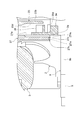
- FIG. 1 is a cross-sectional view showing a fluid machine according to an embodiment of the present disclosure.
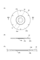
- FIG. 2 is a view of the motor housing in FIG. 1 as viewed from the second end side in the axial direction.
- 3 (A) is a front view showing the flow path forming plate in FIG. 1
- FIG. 3 (B) is a cross-sectional view taken along the line IIIB-IIIB in FIG. 3 (A)
- FIG. It is a principal part enlarged view of FIG. 3 (B).
- FIG. 4 (A) is a front view showing the cooling fan in FIG. 1
- FIG. 4 (B) is a cross-sectional view taken along the line IVB-IVB in FIG. 4 (A).
- FIG. 5 is a cross-sectional view showing a seal formed around the boss of the impeller in FIG.
- a fluid machine includes a motor housing including a first end and a second end in an axial direction, and a protrusion inserted through the motor housing and protruding from the first end or the second end of the motor housing.
- a rotary shaft including the impeller, an impeller attached to the protrusion of the rotary shaft, a facing portion facing the motor housing at a first end in the axial direction, and a first opening provided at the first end of the motor housing;
- a second opening provided on the second end side of the motor housing and communicating with the outside air, an in-housing flow passage formed in the motor housing and communicating the first opening and the second opening, a motor housing and a facing portion
- An exhaust flow path communicating between the first opening and the outside air, and a swirl vane disposed between the first opening and the exhaust flow path, attached to the rotation shaft and rotatable with the rotation shaft And.
- the second opening, the flow passage in the housing, the first opening, and the exhaust flow passage communicate with each other.
- the swirl vanes rotate with the rotation shaft
- the outside air is drawn from the second opening and flows through the plurality of spaces described above.
- the motor can be cooled by the ambient air flowing in the motor housing.
- outside air is drawn into the motor housing as cooling air separately from the main flow.
- the impeller is attached to a protrusion that projects from the first end of the motor housing, the facing portion is disposed between the first end of the motor housing and the impeller, and a portion of the back of the impeller is It is located on the motor housing side of the facing part.
- the facing portion defines the main flow path generated by the impeller and the flow path of the cooling air flowing in the motor housing. Since a part of the back surface of the impeller is located on the motor housing side of the facing portion, axial compactification is achieved.
- a coil is fixed to the inner circumferential surface of the motor housing, and the motor housing includes a groove formed on the inner circumferential surface and extending in the axial direction over the area provided with the coil.
- the cooling air can easily flow in the motor housing through the groove. The cooling air tends to cool the coil.
- the coil is axially spaced apart from the first end and the second end of the motor housing. In this case, the outside air is easily introduced into the groove in the motor housing. As a result, the cooling efficiency of the coil is improved.
- the fluid machine further comprises a cooling fan formed with pivoting vanes, the cooling fan including a boss through which the rotation shaft is inserted, and the impeller projecting from the first end of the motor housing
- the rotating shaft includes a stepped portion opposed to the back surface of the impeller, and the cooling fan is attached to the rotating shaft by holding the boss between the impeller and the stepped portion of the rotating shaft.
- the cooling fan can be attached to the rotating shaft using the impeller and the step portion provided on the rotating shaft.
- the impeller is screwed into a projection that projects from the first end of the motor housing and presses the cooling fan boss at the back of the impeller.
- the cooling fan can be securely and easily attached to the rotating shaft by screwing the impeller to the rotating shaft.
- the swirl vane includes an inner end, which is an end closer to the rotation axis, and an outer end, which is an end farther from the rotation axis, and extends between the inner end and the outer end.
- the outer end is located upstream of the inner end in the rotational direction of the rotation axis.
- the first opening is located inside the outer end which is the end farther from the rotational axis of the pivoting vanes. In this case, the suction efficiency of the cooling air from within the motor housing by the swirl vanes is improved.
- the fluid machine includes a seal formed on the inner diameter side of the facing portion to seal the motor housing and the impeller.
- FIG. 1 A fluid machine according to an embodiment of the present disclosure will be described with reference to FIG.
- the left side with respect to the paper surface is the tip (first end) side
- the right side with respect to the paper surface is the proximal end (second end) side.
- distal side and proximal side are used with reference to the axial direction.
- a centrifugal fan 1 will be described as an example of a fluid machine.
- the centrifugal blower 1 is, for example, an air-cooled electric blower that sucks in air and delivers it at a predetermined pressure.
- the centrifugal blower 1 is provided with an air inlet on the tip side.
- the centrifugal blower 1 includes an impeller housing 3 in which the impeller 2 is housed, and a motor housing 5 in which a coil 4 which is a rotational drive unit for rotating the impeller 2 is housed.
- the motor housing 5 includes a cylindrical motor housing body 6.
- a radiation fin 7 is formed on the outer peripheral surface of the motor housing main body 6.
- the motor housing main body 6 includes a first end 5a on the distal end side in the axial direction and a second end 5b on the proximal end side.
- the motor housing body 6 includes an insertion hole 6a extending in the axial direction between the first end 5a and the second end 5b.
- a rotating shaft 8 made of, for example, stainless steel is inserted into the motor housing main body 6.
- the rotary shaft 8 is provided in the motor housing main body 6 at a first bearing 18 provided near the first end 5a, and in the motor housing main body 6 near the second end 5b. It is supported by the second bearing portion 11.
- the rotation axis 8 is rotatable about its rotation axis X.
- the rotary shaft 8 has a first end 8 b axially projecting from the first end 5 a of the motor housing main body 6 and a second end 8 c axially projecting from the second end 5 b of the motor housing main body 6. including.
- An impeller 2 made of, for example, aluminum is attached to a first end 8 b which is a projecting portion of the rotating shaft 8. More specifically, a through hole is formed in the impeller 2 along the rotation axis X, and the first end 8 b of the rotation shaft 8 is inserted through the through hole.
- an external thread is formed on the circumferential surface of the first end 8 b.
- a boss portion 2 a that protrudes in the back direction is formed.
- the motor housing main body 6 includes a first opening formed on the distal end side of the insertion hole 6a and a second opening formed on the proximal end side of the insertion hole 6a.
- the insertion hole 6a includes a first cylindrical portion 6b extending from the first opening to the proximal end, an annular first step 6c having a diameter reduced from the first cylindrical portion 6b, and a base end from the first step 6c.
- a second cylindrical portion 6d extending to the side, an annular second stepped portion 6e reduced in diameter from the second cylindrical portion 6d, a third cylindrical portion 6f extending to the base end side from the second stepped portion 6e, and And an annular third step portion 6g expanding in diameter from the third cylindrical portion 6f, and a fourth cylindrical portion 6h extending from the third step portion 6g to the second opening.
- the diameter of the first cylindrical portion 6b is larger than the diameter of the second cylindrical portion 6d.
- the diameter of the second cylindrical portion 6d and the diameter of the fourth cylindrical portion 6h are respectively larger than the diameter of the third cylindrical portion 6f.
- the third cylindrical portion 6 f is, for example, a portion having the smallest diameter in the insertion hole 6 a of the motor housing main body 6.
- a rotor 8 a is fixed to the axial center of the rotation shaft 8.
- the outer diameter of the rotor 8 a is larger than the diameter of the other portion of the rotating shaft 8.
- the rotor 8a includes a generation source of a magnetic field such as a permanent magnet.
- the rotor 8 a is accommodated in the motor housing main body 6. That is, both axial ends of the rotor 8 a are located between the first end 5 a and the second end 5 b of the motor housing body 6.
- Coil 4 is, for example, an electromagnetic coil.
- the coil 4 is fixed to the third cylindrical portion 6 f (inner peripheral surface) of the motor housing main body 6.
- the coil 4 may include, for example, a conductive wire and a stator core which is an iron core wound with the conductive wire (all not shown).
- the coil 4 is disposed around the rotor 8a and faces the rotor 8a with a gap.
- the motor 10 of the present embodiment is configured by the stator including the coil 4 and the rotor 8 a.
- the coil 4 can be energized via a wire not shown. By energizing the coil 4, a rotating magnetic field is generated between the coil 4 and the rotor 8a, and the rotor 8a rotates.
- the coil 4 is axially separated from the first end 5 a and the second end 5 b of the motor housing 5.
- the coil 4 is shorter than the length between the first end 5a and the second end 5b in the axial direction.
- the coil 4 is shorter than, for example, the length of the third cylindrical portion 6f in the axial direction.
- the coil 4 is housed in the third cylindrical portion 6f.
- One or more grooves 9 are provided in the motor housing body 6.
- the direction in which the groove 9 extends is divided into an axial component and a circumferential component
- the direction in which the groove 9 extends includes at least an axial component.
- the groove 9 is formed, for example, in the third cylindrical portion 6f, and is connected to the second step 6e and the third step 6g.
- the bottom of the groove 9 (the part farthest from the rotation axis X) is radially spaced from the coil 4 provided in the third cylindrical part.
- the groove 9 defines an axially extending space on the outer peripheral side of the coil 4.
- a plurality of grooves 9 are formed.
- the plurality of grooves 9 are formed, for example, with a predetermined angular pitch.
- six grooves 9 are formed at an angular pitch of 60 °.
- the plurality of grooves 9 extend axially and may be parallel to one another.
- the groove or grooves 9 may extend helically about the rotation axis X.
- the groove 9 extends in the axial direction over the area in which the coil 4 is provided. In other words, the groove 9 is longer than the length of the coil 4 in the axial direction.
- a portion of the rotary shaft 8 located on the tip end side of the rotor 8 a is supported by the first bearing portion 18.
- a portion of the rotary shaft 8 located on the proximal side of the rotor 8 a is supported by the second bearing portion 11. That is, the rotating shaft 8 is rotatably supported by the first bearing portion 18 and the second bearing portion 11.
- the first bearing portion 18 is a cylindrical support portion 18 b that faces the rotation shaft 8 to support the rotation shaft 8, and a flange that is provided at a base end portion in the axial direction of the support portion 18 b and protrudes radially outward. And a unit 18a.
- the second bearing portion 11 is a cylindrical support portion 11 b facing the rotation shaft 8 to support the rotation shaft 8, and a flange portion provided at the tip end portion in the axial direction of the support portion 11 b and protruding radially outward And 11a.
- a first bearing plate 19 is fitted to the second cylindrical portion 6 d of the motor housing main body 6.
- the first bearing plate 19 is an annular member that is fitted on the first end 5 a side of the motor housing main body 6 and holds the first bearing 18.
- the second bearing plate 12 is fitted to the fourth cylindrical portion 6 h of the motor housing main body 6.
- the second bearing plate 12 is an annular member that is fitted on the second end 5 b side of the motor housing main body 6 and holds the second bearing portion 11.
- the second bearing plate 12 will be described with reference to FIGS. 1 and 2.
- the first bearing plate 19 may have the same structure as the second bearing plate 12.
- the first bearing plate 19 and the first bearing portion 18 have, for example, a plane-symmetrical structure with the second bearing plate 12 and the second bearing portion 11 with respect to a plane perpendicular to the rotation axis X.
- the second bearing plate 12 will be described, and a detailed description of the first bearing plate 19 will be omitted.
- the second bearing plate 12 has a cylindrical rim portion 12 a fitted to the fourth cylindrical portion 6 h of the motor housing main body 6 and a cylindrical shape to which the second bearing portion 11 is fixed. It includes a hub portion 12c and a plurality of spoke portions 12b connecting the rim portion 12a and the hub portion 12c.
- the hub portion 12c is provided with an insertion hole 12d penetrating in the axial direction. The rotary shaft 8 supported by the support portion 11 b and the support portion 11 b is inserted into the insertion hole 12 d.
- the rim portion 12 a of the second bearing plate 12 is fitted into the fourth cylindrical portion 6 h of the motor housing main body 6 and is fixed to the third step portion 6 g by a bolt or the like.
- the flange portion 11 a of the second bearing portion 11 is fixed to the hub portion 12 c of the second bearing plate 12 by a bolt or the like.
- the second bearing portion 11 is fixed to the hub portion 12c.
- the second bearing plate 12 restrains axial and radial displacements of the second bearing portion 11.
- a plurality of intake ports (second openings) 14 penetrating in the axial direction are provided on the outer peripheral side of the hub portion 12c of the second bearing plate 12.
- the intake ports 14 communicate with a space on the second end 5 b side of the motor housing main body 6 and an opening on the proximal end side of the third cylindrical portion 6 f.
- An area not blocked by the spokes 12 b between the rim 12 a and the hub 12 c is an air inlet 14.
- the intake port 14 is provided on the side of the second end 5 b of the motor housing 5 and communicates with the outside air, and communicates with the insertion hole 6 a of the motor housing main body 6.
- a plurality of intake ports 14 are formed in the second bearing plate 12 at a predetermined angular pitch.
- the air intake port 14 may be provided with a filter (not shown) such as a dustproof filter.
- the first bearing plate 19 also includes a rim portion, a hub portion, and a plurality of spoke portions.
- the rim portion of the first bearing plate 19 is fitted into the second cylindrical portion 6 d of the motor housing main body 6 and is fixed to the second step portion 6 e.
- the flange portion 18 a of the first bearing portion 18 is fixed to the hub portion of the first bearing plate 19.
- the first bearing plate 19 restrains axial and radial displacements of the first bearing portion 18.
- a plurality of openings 20 are formed on the outer peripheral side of the hub portion, for example, at a predetermined angular pitch.
- the opening 20 communicates with the opening on the tip end side of the third cylindrical portion 6 f. That is, the opening 20 communicates with the insertion hole 6 a of the motor housing main body 6.
- the flow path forming plate 23 provided at the first end 5a of the motor housing 5 will be described.
- an annular flow path forming plate 23 is fitted in the first cylindrical portion 6b of the motor housing main body 6.
- the flow path forming plate 23 includes an annular outer peripheral plate portion 23a fitted to the first cylindrical portion 6b, and an inner peripheral plate portion 23b continuous to the inner side of the outer peripheral plate portion 23a.
- a circular flow passage forming hole 23c penetrating in the axial direction is formed.
- the inner peripheral plate portion 23b is thinner than the outer peripheral plate portion 23a in the axial direction. More specifically, the outer peripheral plate portion 23a has a constant thickness.
- the inner circumferential plate portion 23b is inclined from the inner circumferential end of the outer circumferential plate portion 23a toward the flow passage forming hole 23c, and becomes thinner toward the flow passage forming hole 23c.
- the back surface facing the insertion hole 6a of the flow channel forming plate 23 (facing the coil 4) is flat, the surface of the flow channel forming plate 23 which is the opposite side has a hollow portion 23d (see FIG. And FIG. 3 (C)).
- the flow path forming plate 23 may protrude from the first opening on the tip end side of the motor housing main body 6. That is, a part of the flow path forming plate 23 in the thickness direction (axial direction) may be fitted to the first cylindrical portion 6 b.
- the flow path forming plate 23 is axially separated from the first bearing plate 19.
- the flow path forming plate 23 is also separated from the first bearing portion 18 attached to the first bearing plate 19. That is, a space 24 extending in the radial direction is formed between the flow path forming plate 23 and the first bearing plate 19.
- the opening 20 of the first bearing plate 19 communicates the insertion hole 6 a of the motor housing main body 6 with the space 24.
- the flow passage forming hole 23 c provided in the flow passage forming plate 23 is formed around, for example, the rotation axis X.
- the flow passage forming hole 23 c forms an exhaust port (first opening) 25 provided on the first end 5 a side of the motor housing 5.
- the flow path forming hole 23 c that is, the exhaust port 25 communicates with the insertion hole 6 a, the opening 20, and the space 24.
- the rotation shaft 8 is inserted into the flow passage forming hole 23c.
- the exhaust port 25 is smaller than the intake port 14. The size of the exhaust port 25 may be changed as appropriate.
- the motor housing 5 is configured by the above-described motor housing body 6, the second bearing plate 12, the first bearing plate 19, the flow path forming plate 23, and the like.
- an in-housing flow passage 50 communicating the intake port 14 and the exhaust port 25 is formed.
- the flow path 50 in the housing includes the inner wall surface of the motor housing main body 6, and the coil 4, the rotary shaft 8, the second bearing plate 12, the second bearing portion 11, the first bearing plate 19, and the first bearing portion 18. It is formed in the gap between.
- the impeller 2 attached to the first end 8 b of the rotating shaft 8 is housed in the impeller housing 3.
- the impeller housing 3 communicates with the opening 30a, which is a suction port provided on the tip end side in the axial direction, the suction flow path 30 extending from the opening 30a to the base end side, and the suction flow path 30, and encloses the impeller 2 And a scroll 31 provided on the outer periphery of the diffuser 29 and in communication with the diffuser 29, and an outlet for air provided downstream of the scroll 31.
- the impeller housing 3 includes, for example, an impeller housing main body portion 26 and a disc-like closing plate 27 attached to the base end side of the impeller housing main body portion 26.
- the scroll 31 described above is formed in the impeller housing main body 26.
- the impeller housing main body portion 26 has a circular opening 30a of the suction flow passage 30 formed on the tip end side, and is axially opposed to the opening 30a while communicating with the suction flow passage 30 and having a circular shape formed on the proximal end side. And an opening 39.
- the closing plate 27 is disposed on the back side (the rotor 8 a side) of the impeller 2.
- the closing plate 27 is fitted in, for example, the opening 39 on the proximal end side of the impeller housing main body 26.
- the closing plate 27 and the impeller housing main body 26 are fixed to each other, for example, by bolts or the like.
- the closing plate 27 includes a first surface 27 f provided on the impeller 2 side and a second surface 27 g provided on the motor housing 5 side.
- the first surface 27 f, together with the impeller housing 3, defines a diffuser 29.
- An O-ring 28 is disposed on the outer periphery of the opening B of the impeller housing main body 26.
- the flow path of the main flow 32 is sealed by the impeller housing main body 26 and the closing plate 27 sandwiching the O-ring 28.
- a recessed surface (facing portion) 27a that is recessed toward the impeller 2 is formed. Is disposed between the motor housing 5 and the impeller 2. In the axial direction, the first end 5 a of the motor housing main body 6 is located closer to the impeller 2 than the second surface 27 g of the closing plate 27. The first end 5a of the motor housing main body 6 is in the recess formed by the recess surface 27a. In other words, the recessed surface 27 a receives the first end 5 a of the motor housing body 6. The recessed surface 27a faces the motor housing 5 on the side of the first end 5a in the axial direction.
- the first end 5a of the motor housing body 6 and the recessed surface 27a are separated in the axial direction. Between the first end 5a of the motor housing main body 6 and the recessed surface 27a, an exhaust flow passage 33 communicating the exhaust port 25 with the outside air is formed.
- a circular through hole 27 h penetrating in the axial direction is formed at the center of the closing plate 27.
- the boss portion 2 a provided on the back surface of the impeller 2 is inserted into the through hole 27 h. That is, the boss portion 2 a passes through the closing plate 27.
- the axial length of the boss portion 2 a is substantially equal to the axial length of the through hole 27 h of the closing plate 27.
- a part of the back surface of the impeller 2 is located on the motor housing 5 side of the recessed surface 27a.
- the closing plate 27 includes a seal portion 27 k facing the boss portion 2 a of the impeller 2 on the inner diameter side.
- the seal portion 27k is formed at the peripheral portion of the through hole 27h described above.
- the seal portion 27 k seals the motor housing body 6 (motor housing 5) and the impeller 2.
- the seal portion 27k is formed on both sides in the axial direction of an annular recess 27n separated from the boss portion 2a in the radial direction and in the axial direction of the recess 27n and has an annular shape projecting toward the boss portion 2a of the impeller 2 from the bottom of the recess 27n.
- a convex portion 27m is formed on both sides in the axial direction of an annular recess 27n separated from the boss portion 2a in the radial direction and in the axial direction of the recess 27n and has an annular shape projecting toward the boss portion 2a of the impeller 2 from the bottom of the recess 27n.
- a convex portion 27m
- a groove is formed on the inner peripheral surface of the seal portion 27k in the circumferential direction.
- the groove of the seal portion 27k of the present embodiment is rectangular in cross section in the axial direction.
- the boss portion 2a of the impeller 2 and the convex portion 27m of the seal portion 27k are separated in the radial direction.
- the seal portion 27 k forms a noncontact seal structure with the boss portion 2 a of the impeller 2.
- the recessed surface 27a of the closure plate 27 includes a plurality of slopes.
- the depressed surface 27a includes a first inclined portion 27b, a second inclined portion 27c, a third inclined portion 27d, and a fourth inclined portion 27e from the outer peripheral side.
- An annular flat portion is formed between the inclined portions.
- the first inclined portion 27 b and the second inclined portion 27 c are located on the outer peripheral side of the first cylindrical portion 6 b of the motor housing main body 6.
- the first inclined portion 27 b extends in the axial direction from the tip end side (impeller 2 side) to the base end side (coil 4 side) from the first end 5 a of the motor housing main body 6.
- the step of the fourth inclined portion 27e is smaller than any of the steps of the first inclined portion 27b, the steps of the second inclined portion 27c, and the steps of the third inclined portion 27d.
- a depressed surface 27 a formed of the inclined portion and the flat portion faces the flow passage forming plate 23 provided at the first end 5 a of the motor housing 5, and between the depressed surface 27 a and the flow passage forming plate 23.
- a radially extending exhaust passage 33 is formed. The exhaust flow path 33 communicates with the exhaust port 25 at the center and communicates with the outside air at the outer peripheral end.
- a screw seat (not shown) is formed on the closing plate 27 so as to protrude proximally at a predetermined angular pitch.
- the closing plate 27 and the motor housing main body 6 are fastened with a bolt or the like through the screw seat.
- the closing plate 27 and the motor housing main body 6 are fastened with a bolt or the like.
- the impeller housing 3 and the motor housing 5 are connected in a state in which the closing plate 27 is interposed. Then, an exhaust flow passage 33 is formed between the flow passage forming plate 23 and the closing plate 27.
- a tip end side middle diameter portion 8 d is formed on the tip end side of the flow path forming plate 23 of the rotation shaft 8.
- a cooling fan 34 made of, for example, aluminum is inserted into the tip end side middle diameter portion 8d.
- the cooling fan 34 is provided in the exhaust flow path 33 so as to face the exhaust port 25.
- the cooling fan 34 includes a boss portion 35a into which the tip end side middle diameter portion 8d of the rotating shaft 8 is inserted.
- An insertion hole 34a is formed in the boss portion 35a, and a tip end side middle diameter portion 8d is inserted into the insertion hole 34a.
- the rotary shaft 8 is formed with an annular step portion 8f which is continuous with the tip end side middle diameter portion 8d and has a diameter larger than that of the tip end side middle diameter portion 8d.
- the stepped portion 8 f is located between the motor housing main body 6 and the impeller 2 and faces the boss 2 a of the impeller 2.
- a tip end small diameter portion 8e is formed on the tip end side of the tip end side middle diameter portion 8d.
- the tip side small diameter portion 8 e corresponds to the first end 8 b described above.
- the impeller 2 is inserted into the tip side small diameter portion 8e.
- a fastening nut is screwed on the tip end side of the impeller 2.
- By tightening the fastening nut an axial force is generated, and the impeller 2 and the cooling fan 34 are attached to the rotating shaft 8.
- a pressing force to the boss 2 a of the impeller 2 and the cooling fan 34 is generated from the fastening nut. That is, the boss portion 35 a of the cooling fan 34 and the impeller 2 are nipped by the stepped portion 8 f of the rotating shaft 8 and the fastening nut.
- the impeller 2 presses the boss 35 a of the cooling fan 34 with the boss 2 a which is a part of the rear surface.
- a gap is formed between the hub portion of the impeller 2 and the cooling fan 34, and the closing plate 27 described above is located in the gap.
- the cooling fan 34 has a boss 35a, an insertion hole 34a formed in the boss 35a, and an end face of the boss 35a in the radial direction. It includes a disk portion 35 extending outward, and a plurality of blade portions (swing blades) 36 provided upright on the disk portion 35 and projecting to the base end side. That is, the blade portion 36 is attached to the first end 8 b of the rotating shaft 8 via the disk portion 35.
- the vane portion 36 is disposed between the exhaust port 25 and the exhaust flow path 33 and can rotate with the rotation shaft 8.
- the boss portion 35 a and the blade portion 36 are separated in the radial direction.
- the plurality of vanes 36 are spaced apart from one another in the circumferential direction, for example, arranged at equal intervals.
- Each wing portion 36 includes an inner end 36 b which is an end closer to the rotation axis 8 and an outer end 36 a which is an end remote from the rotation axis 8, and between the inner end 36 b and the outer end 36 a It is stretched by.
- the outer end 36 a is located upstream of the inner end 36 b in the rotational direction R of the rotation shaft 8.
- Each blade 36 extends from the inner end 36 b toward the outer end 36 a in the direction opposite to the rotational direction R.
- the blade portion 36 is formed, for example, to the vicinity of the outer peripheral end of the disk portion 35.
- the bosses 35 a of the cooling fan 34 are located on the inner peripheral side of the flow path forming plate 23.
- the diameter of the cooling fan 34 is larger than the diameter of the exhaust port 25 of the flow path forming plate 23.
- the blade portion 36 extends from the flow passage forming hole 23 c (see FIG. 3B) of the flow passage forming plate 23 to the outer peripheral side.
- the exhaust port 25 is located inside the outer end 36 a of the blade portion 36.
- the outer end 36 a of the blade portion 36 is provided in the range of the recessed portion 23 d of the flow path forming plate 23 in the radial direction.
- a part of the wing portion 36 (the tip end farthest from the disk portion 35 in the axial direction) may enter the recess 23 d of the flow path forming plate 23.
- the recess 23 d of the flow path forming plate 23 may receive a part of the blade 36.
- the centrifugal blower 1 can be used, for example, for blowing or sucking air.
- an object to be blown is provided at the end (that is, the downstream side) of the outlet of the main flow 32.
- a suction target is provided in front of (that is, upstream of) the suction port (opening 30 a) of the main flow 32.
- the impeller 2 rotates with the rotation of the rotating shaft 8, and the main flow 32 is sucked into the impeller housing 3 by the rotation of the impeller 2.
- the centrifugal blower 1 When the centrifugal blower 1 is used for suction, air is suctioned from a predetermined suction target.
- the centrifugal fan 1 When the centrifugal fan 1 is used for blowing air, the main flow 32 sucked into the impeller housing 3 is blown to a predetermined air-blowing object through the diffuser 29 and the scroll 31.
- the cooling fan 34 rotates with the rotation of the rotating shaft 8.
- the rotation of the cooling fan 34 sucks the inside of the motor housing 5 from the exhaust port 25.
- the inside of the motor housing 5 has a negative pressure, and outside air is sucked as cooling air 38 into the motor housing 5 through the air inlet 14.
- the cooling air 38 sucked from the air inlet 14 circulates between the coil 4 and the rotor 8 a and the in-housing flow path 50 formed in the motor housing main body 6.
- the cooling air 38 can also flow in the groove 9 formed in the inner peripheral surface of the motor housing main body 6.
- the cooling air 38 flowing in the motor housing main body 6 reaches the space 24 through the opening 20.
- the cooling air 38 that has reached the space 24 is deflected toward the center by the flow path forming plate 23.
- the cooling air 38 deflected in the center direction is exhausted to the outside of the motor housing 5 through the exhaust port 25.
- the cooling air 38 exhausted from the exhaust port 25 and sucked into the cooling fan 34 is exhausted radially outward, flows through the exhaust flow path 33, is guided by the recessed surface 27a including the plurality of inclined portions, and the centrifugal fan 1 Exhaust to the outside of the
- the heat source such as the coil 4 including the lead wire and the stator core generates heat, but the coil 4 is cooled by the cooling air 38 flowing in the motor housing main body 6 and further exchanges heat with the outside air. It is cooled by the radiation fin 7 which carries out.
- heat sources other than the coil 4 include a rotor 8a including a permanent magnet, a first bearing 18 and a second bearing 11, an air gap, and the like.
- the air gap is a flow of air in the rotational direction (rotational direction R) of the rotor 8 a that may occur between the rotor 8 a and the coil 4.
- An air gap causes a windage loss.
- all of the heat sources described above are cooled directly or indirectly.
- the intake port 14, the in-housing flow path 50, the exhaust port 25, and the exhaust flow path 33 communicate with each other.
- the blade 36 rotates with the rotation shaft 8
- the outside air is drawn from the air inlet 14 and flows through the plurality of spaces described above.
- the motor 10 and the like including the coil 4 and the rotor 8a can be cooled.
- outside air is drawn into the motor housing 5 as the cooling air 38 separately from the main flow 32.
- the recessed surface 27 a defines a flow path of the main flow 32 generated by the impeller 2 and a flow path of the cooling air 38 flowing in the motor housing 5. Since the boss portion 2a on the back surface of the impeller 2 is positioned on the motor housing 5 side of the recessed surface 27a, the axial size can be reduced.
- the cooling air 38 easily flows in the motor housing 5 through the groove 9 formed in the inner peripheral surface of the motor housing 5.
- the cooling air 38 easily cools the heat source such as the coil 4.
- the cooling air 38 flowing in the groove 9 can directly cool the coil 4 and the stator core of the rotor 8a.
- the cooling air 38 may also indirectly cool the heat source other than the coil 4 and the stator core.
- the coil 4 Since the coil 4 is separated from the first end 5 a and the second end 5 b of the motor housing 5 in the axial direction, outside air can be easily introduced into the groove 9 in the motor housing 5. As a result, the cooling efficiency of the coil 4 is improved.
- the cooling fan 34 can be attached to the rotating shaft 8 by using the impeller 2 and the step portion 8 f provided on the rotating shaft 8.
- the configuration is simple and space saving in the axial direction is possible.
- vanes 36 are inclined in the direction opposite to the rotational direction R with respect to the radial direction, the rotation of the vanes 36 can produce a good flow from the flow passage 50 in the housing to the exhaust flow passage 33.
- the exhaust port 25 is positioned inside the outer end 36 a of the blade 36, the efficiency of suction of the cooling air 38 from the inside of the motor housing 5 by the blade 36 is improved.
- the cooling fan 34 is provided on the rotating shaft 8 and rotates with the impeller 2. Therefore, it is not necessary to separately provide a motor for rotating the cooling fan 34.
- the manufacturing cost of the centrifugal blower 1 can be reduced, and the apparatus can be miniaturized, as compared with the case where a motor for drawing in the outside air as cooling air is separately provided.
- a flow path forming plate 23 is provided between the impeller housing 3 and the motor housing 5, an exhaust port 25 is provided between the flow path forming plate 23 and the rotary shaft 8, and the cooling fan 34 is opposed to the exhaust port 25. Since it is provided, the cooling air 38 can be exhausted to the outside of the motor housing 5 without increasing the size of the cooling fan 34.
- an exhaust flow passage 33 is formed between the flow passage forming plate 23 and the closing plate 27 of the impeller housing 3, and the flow passage forming plate 23 separates the flow passage of the cooling air 38 sucked and discharged by the cooling fan 34. Ru. Accordingly, the interference between the cooling air 38 sucked by the cooling fan 34 and the cooling air 38 exhausted can be suppressed, and the exhaust efficiency of the cooling air 38 can be improved.
- cooling air 38 is exhausted to the outside of the centrifugal fan 1 by the cooling fan 34 and the exhaust flow path 33. Even when the high temperature main flow 32 flows from the impeller housing 3, the main flow 32 can be suppressed from flowing into the motor housing 5.
- an internal thread may be formed on the circumferential surface of the through hole of the impeller 2. Then, the impeller 2 may be screwed into the first end 8 b of the rotating shaft 8, and the boss portion 2 a which is a part of the back surface of the impeller 2 may press the boss portion 35 a of the cooling fan 34. According to this configuration, the cooling fan 34 can be attached to the rotating shaft 8 reliably and easily.
- the facing portion facing the motor housing 5 at the first end 5 a in the axial direction is not limited to the case formed by the closing plate 27 which is a single member.
- the facing portion may be formed by a portion integrally formed on the impeller housing 3 or may be formed by a portion integrally formed on the motor housing 5.
- a member such as a closure plate 27 may be attached to the motor housing 5.
- a flat facing portion may be provided without forming a recessed surface.
- the seal portion formed on the closing plate 27 is not limited to the non-contact type seal portion 27k as in the above embodiment. For example, when the rotation speed of the impeller 2 is low, the seal portion of the closing plate 27 may form a contact-type seal structure that contacts the boss portion 2 a of the impeller 2 and seals the impeller 2.
- the sealing portion of the closing plate 27 may be omitted.
- the cooling fan 34 may be an axial fan provided in the exhaust port 25 or may be another type of fan.
- the pivoting vanes may be attached directly to the rotating shaft 8.
- FIG. 1 a first opening, an exhaust flow passage, and a swirl vane are provided on the first end 5a side of the motor housing 5, but the impeller 2 is provided on the opposite second end 5b side.
- the impeller housing body 26 and the closing plate 27 are separated.
- the closing plate 27 is provided on the first end 5 a side of the motor housing 5, and the impeller housing main body 26 and the impeller 2 are provided on the second end 5 b side of the motor housing 5.
- the cooling structure has been described taking the centrifugal blower 1 as an example, but the present invention is also applicable to a centrifugal compressor.
- the fluid machine to which the present invention is applied may be an axial flow type blower or compressor.
- outside air is drawn into the motor housing 5 as cooling air separately from the main flow.
Abstract
A fluid machine comprising: a motor housing; a rotary shaft inserted into the motor housing; an impeller attached to an extension part of the rotary shaft; a facing section facing the motor housing at a first end in the axial direction; a first opening provided at the first end of the motor housing; a second opening provided at a second end of the motor housing; a housing internal flow path connecting the first opening and the second opening; an exhaust flow path provided between the motor housing and the facing section, and enabling the first opening to communicate with the outside air; and swirl vanes that are arranged between the first opening and the exhaust flow path and are attached to the rotary shaft, and are capable of rotating together with the rotary shaft.
Description
本開示は、流体機械に関する。
The present disclosure relates to fluid machines.
遠心式の送風機や圧縮機等の流体機械は、モータを含み得る。モータは、ロータとロータを囲むコイルとを含む。モータのロータは、コイルが生じる回転磁界により回転する。ロータにはインペラが取り付けられており、そのインペラが回転することで、流体機械は空気を吸入する。コイルから回転磁界が生じロータが回転すると、コイルやロータが発熱し、モータの温度が上昇し得る。モータの温度が上昇すると、モータの回転効率が低下し、送風機や圧縮機の運用効率が低下する。また、部品の材質が制限されるため、モータを冷却する必要がある。
A fluid machine such as a centrifugal fan or compressor may include a motor. The motor includes a rotor and a coil surrounding the rotor. The rotor of the motor is rotated by the rotating magnetic field generated by the coil. An impeller is attached to the rotor, and the fluid machine sucks air as the impeller rotates. When a rotating magnetic field is generated from the coil and the rotor rotates, the coil and the rotor generate heat, and the temperature of the motor may rise. When the temperature of the motor rises, the rotation efficiency of the motor decreases, and the operation efficiency of the blower and the compressor decreases. In addition, since the material of parts is limited, it is necessary to cool the motor.
モータを冷却する手段としては、従来、たとえば主流または主流の一部を冷却空気として用いるものがあった。従来の手段では、インペラの回転により主流を吸入し、外部へと排気する過程で、主流または主流の一部をモータの周囲に流通させ、モータの冷却を行っていた。
As a means for cooling a motor, for example, a main stream or a part of the main stream has been used as cooling air. In the conventional means, the main stream or a part of the main stream is circulated around the motor to cool the motor in the process of sucking the main stream by rotation of the impeller and exhausting it to the outside.
たとえば特許文献1に記載の構成では、ファンケースの導風口から空気が取り入れられ、その空気がファンの羽根部に案内される。その空気は、ディフューザからモータケースの内部に送り込まれ、モータの回転子の鉄心に形成された絶縁スロットの周囲等を通り抜ける。その空気は、モータを冷却した後、モータケースの外部へと排気される。
For example, in the configuration described in Patent Document 1, air is taken in from the air guide opening of the fan case, and the air is guided to the blade portion of the fan. The air is fed from the diffuser into the interior of the motor case and passes around the insulating slot formed in the iron core of the motor rotor. The air is exhausted to the outside of the motor case after cooling the motor.
従来の構成では、主流や主流の一部が冷却空気として用いられる場合、主流自体が、外気等のようにモータを冷却可能な温度である必要があった。たとえば、主流の温度が高い場合には、主流や主流の一部を冷却空気として用いることができなかった。
In the conventional configuration, when the main stream or a part of the main stream is used as the cooling air, the main stream itself needs to have a temperature capable of cooling the motor like outside air or the like. For example, when the temperature of the main stream is high, the main stream or a part of the main stream can not be used as the cooling air.
本開示は、主流とは別に冷却空気として外気を吸入する構造を備えた流体機械を説明する。
The present disclosure describes a fluid machine having a structure that sucks outside air as cooling air separately from the main flow.
本開示の一態様に係る流体機械は、軸方向における第1端と第2端とを含むモータハウジングと、モータハウジングに挿通され、モータハウジングの第1端または第2端から突出する突出部を含む回転軸と、回転軸の突出部に取り付けられたインペラと、軸方向の第1端側でモータハウジングに対面する対面部と、モータハウジングの第1端側に設けられた第1開口と、モータハウジングの第2端側に設けられ、外気と連通する第2開口と、モータハウジング内に形成され、第1開口と第2開口とを連通するハウジング内流路と、モータハウジングと対面部との間に形成され、第1開口と外気とを連通する排気流路と、第1開口と排気流路との間に配置され、回転軸に取り付けられて回転軸とともに回転可能である旋回羽根と、を備える。
A fluid machine according to an aspect of the present disclosure includes a motor housing including a first end and a second end in an axial direction, and a protrusion inserted through the motor housing and protruding from the first end or the second end of the motor housing. A rotary shaft including the impeller, an impeller attached to the protrusion of the rotary shaft, a facing portion facing the motor housing at a first end in the axial direction, and a first opening provided at the first end of the motor housing; A second opening provided on the second end side of the motor housing and communicating with the outside air, an in-housing flow passage formed in the motor housing and communicating the first opening and the second opening, a motor housing and a facing portion An exhaust flow path communicating between the first opening and the outside air, and a swirl vane disposed between the first opening and the exhaust flow path, attached to the rotation shaft and rotatable with the rotation shaft And.
本開示の一態様によれば、主流とは別に、外気が冷却空気としてモータハウジング内に吸入される。
According to one aspect of the present disclosure, outside air is drawn into the motor housing as cooling air separately from the main flow.
本開示の一態様に係る流体機械は、軸方向における第1端と第2端とを含むモータハウジングと、モータハウジングに挿通され、モータハウジングの第1端または第2端から突出する突出部を含む回転軸と、回転軸の突出部に取り付けられたインペラと、軸方向の第1端側でモータハウジングに対面する対面部と、モータハウジングの第1端側に設けられた第1開口と、モータハウジングの第2端側に設けられ、外気と連通する第2開口と、モータハウジング内に形成され、第1開口と第2開口とを連通するハウジング内流路と、モータハウジングと対面部との間に形成され、第1開口と外気とを連通する排気流路と、第1開口と排気流路との間に配置され、回転軸に取り付けられて回転軸とともに回転可能である旋回羽根と、を備える。
A fluid machine according to an aspect of the present disclosure includes a motor housing including a first end and a second end in an axial direction, and a protrusion inserted through the motor housing and protruding from the first end or the second end of the motor housing. A rotary shaft including the impeller, an impeller attached to the protrusion of the rotary shaft, a facing portion facing the motor housing at a first end in the axial direction, and a first opening provided at the first end of the motor housing; A second opening provided on the second end side of the motor housing and communicating with the outside air, an in-housing flow passage formed in the motor housing and communicating the first opening and the second opening, a motor housing and a facing portion An exhaust flow path communicating between the first opening and the outside air, and a swirl vane disposed between the first opening and the exhaust flow path, attached to the rotation shaft and rotatable with the rotation shaft And.
この流体機械によれば、第2開口と、ハウジング内流路と、第1開口と、排気流路とが互いに連通する。回転軸とともに旋回羽根が回転すると、外気は、第2開口から吸入され、上記した複数の空間を流れる。外気がモータハウジング内を流れることにより、モータが冷却され得る。これにより、主流とは別に、外気が冷却空気としてモータハウジング内に吸入される。
According to this fluid machine, the second opening, the flow passage in the housing, the first opening, and the exhaust flow passage communicate with each other. When the swirl vanes rotate with the rotation shaft, the outside air is drawn from the second opening and flows through the plurality of spaces described above. The motor can be cooled by the ambient air flowing in the motor housing. Thus, outside air is drawn into the motor housing as cooling air separately from the main flow.
いくつかの態様において、インペラは、モータハウジングの第1端から突出する突出部に取り付けられ、対面部は、モータハウジングの第1端とインペラとの間に配置され、インペラの背面の一部が対面部のモータハウジング側に位置している。この場合、対面部が、インペラによって生じる主流の流路と、モータハウジング内を流れる冷却空気の流路とを画成する。インペラの背面の一部が対面部のモータハウジング側に位置するので、軸方向のコンパクト化が図られる。
In some aspects, the impeller is attached to a protrusion that projects from the first end of the motor housing, the facing portion is disposed between the first end of the motor housing and the impeller, and a portion of the back of the impeller is It is located on the motor housing side of the facing part. In this case, the facing portion defines the main flow path generated by the impeller and the flow path of the cooling air flowing in the motor housing. Since a part of the back surface of the impeller is located on the motor housing side of the facing portion, axial compactification is achieved.
いくつかの態様において、モータハウジングの内周面にはコイルが固定されており、モータハウジングは、内周面に形成され、軸方向においてコイルが設けられた領域にわたって延伸する溝を含む。この場合、溝を通じて、モータハウジング内を冷却空気が流れやすい。冷却空気は、コイルを冷却しやすい。
In some embodiments, a coil is fixed to the inner circumferential surface of the motor housing, and the motor housing includes a groove formed on the inner circumferential surface and extending in the axial direction over the area provided with the coil. In this case, the cooling air can easily flow in the motor housing through the groove. The cooling air tends to cool the coil.
いくつかの態様において、コイルは、軸方向において、モータハウジングの第1端および第2端から離隔している。この場合、外気がモータハウジング内の溝に導入されやすい。その結果として、コイルの冷却効率が向上する。
In some aspects, the coil is axially spaced apart from the first end and the second end of the motor housing. In this case, the outside air is easily introduced into the groove in the motor housing. As a result, the cooling efficiency of the coil is improved.
いくつかの態様において、流体機械は、旋回羽根が形成された冷却ファンを更に備え、冷却ファンは、回転軸が挿通されるボス部を含み、インペラは、モータハウジングの第1端から突出する突出部に取り付けられ、回転軸は、インペラの背面に対向する段差部を含み、冷却ファンは、ボス部がインペラと回転軸の段差部とにより挟持されることで、回転軸に取り付けられている。この場合、インペラと、回転軸に設けられた段差部とを利用して、冷却ファンを回転軸に取り付けることができる。構成が簡易であり、軸方向の省スペース化が可能である。
In some aspects, the fluid machine further comprises a cooling fan formed with pivoting vanes, the cooling fan including a boss through which the rotation shaft is inserted, and the impeller projecting from the first end of the motor housing The rotating shaft includes a stepped portion opposed to the back surface of the impeller, and the cooling fan is attached to the rotating shaft by holding the boss between the impeller and the stepped portion of the rotating shaft. In this case, the cooling fan can be attached to the rotating shaft using the impeller and the step portion provided on the rotating shaft. The configuration is simple and space saving in the axial direction is possible.
いくつかの態様において、インペラは、モータハウジングの第1端から突出する突出部に螺合され、インペラの背面で冷却ファンのボス部を押圧している。この場合、回転軸に対するインペラの螺合により、冷却ファンを確実かつ容易に回転軸に取り付けることができる。
In some aspects, the impeller is screwed into a projection that projects from the first end of the motor housing and presses the cooling fan boss at the back of the impeller. In this case, the cooling fan can be securely and easily attached to the rotating shaft by screwing the impeller to the rotating shaft.
いくつかの態様において、旋回羽根は、回転軸に近い方の端部である内端と、回転軸から遠い方の端部である外端とを含み、内端と外端との間で延伸しており、外端は、内端よりも回転軸の回転方向の上流側に位置する。この場合、旋回羽根の回転は、ハウジング内流路から排気流路への良好な流れを生み出すことができる。
In some embodiments, the swirl vane includes an inner end, which is an end closer to the rotation axis, and an outer end, which is an end farther from the rotation axis, and extends between the inner end and the outer end. The outer end is located upstream of the inner end in the rotational direction of the rotation axis. In this case, the rotation of the swirl vanes can produce a good flow from the flow passage in the housing to the exhaust flow passage.
いくつかの態様において、第1開口は、旋回羽根の回転軸から遠い方の端部である外端より内側に位置する。この場合、旋回羽根によるモータハウジング内からの冷却空気の吸入効率が向上する。
In some embodiments, the first opening is located inside the outer end which is the end farther from the rotational axis of the pivoting vanes. In this case, the suction efficiency of the cooling air from within the motor housing by the swirl vanes is improved.
いくつかの態様において、流体機械は、対面部の内径側に形成され、モータハウジングとインペラとをシールするシール部を備える。
In some aspects, the fluid machine includes a seal formed on the inner diameter side of the facing portion to seal the motor housing and the impeller.
以下、図面を参照しつつ本開示の実施形態を説明する。
Hereinafter, embodiments of the present disclosure will be described with reference to the drawings.
図1を参照して、本開示の実施形態に係る流体機械について説明する。図1において、紙面に対して左側を先端(第1端)側、紙面に対して右側を基端(第2端)側とする。以下の説明において、「先端側」および「基端側」との語は、軸方向を基準として用いられる。
A fluid machine according to an embodiment of the present disclosure will be described with reference to FIG. In FIG. 1, the left side with respect to the paper surface is the tip (first end) side, and the right side with respect to the paper surface is the proximal end (second end) side. In the following description, the terms "distal side" and "proximal side" are used with reference to the axial direction.
本実施形態では、流体機械の一例として、遠心送風機1について説明する。遠心送風機1は、空気を吸い込み所定の圧力で送り出す、たとえば空冷式の電動ブロアである。遠心送風機1は、先端側に空気の吸入口を備える。遠心送風機1は、インペラ2が収納されたインペラハウジング3と、インペラ2を回転させるための回転駆動部であるコイル4が収納されたモータハウジング5とを備えている。
In the present embodiment, a centrifugal fan 1 will be described as an example of a fluid machine. The centrifugal blower 1 is, for example, an air-cooled electric blower that sucks in air and delivers it at a predetermined pressure. The centrifugal blower 1 is provided with an air inlet on the tip side. The centrifugal blower 1 includes an impeller housing 3 in which the impeller 2 is housed, and a motor housing 5 in which a coil 4 which is a rotational drive unit for rotating the impeller 2 is housed.
モータハウジング5は、円筒状のモータハウジング本体部6を含む。モータハウジング本体部6の外周面には、放熱フィン7が形成されている。モータハウジング本体部6は、軸方向における先端側の第1端5aと基端側の第2端5bとを含む。モータハウジング本体部6は、第1端5aと第2端5bの間で軸方向に延びる挿通穴6aを備える。モータハウジング本体部6には、たとえばステンレス製の回転軸8が挿通されている。
The motor housing 5 includes a cylindrical motor housing body 6. A radiation fin 7 is formed on the outer peripheral surface of the motor housing main body 6. The motor housing main body 6 includes a first end 5a on the distal end side in the axial direction and a second end 5b on the proximal end side. The motor housing body 6 includes an insertion hole 6a extending in the axial direction between the first end 5a and the second end 5b. A rotating shaft 8 made of, for example, stainless steel is inserted into the motor housing main body 6.
回転軸8は、モータハウジング本体部6内であって第1端5aの近くに設けられた第1軸受部18と、モータハウジング本体部6内であって第2端5bの近くに設けられた第2軸受部11とによって支持されている。回転軸8は、その回転軸線Xを中心に回転可能である。
The rotary shaft 8 is provided in the motor housing main body 6 at a first bearing 18 provided near the first end 5a, and in the motor housing main body 6 near the second end 5b. It is supported by the second bearing portion 11. The rotation axis 8 is rotatable about its rotation axis X.
回転軸8は、モータハウジング本体部6の第1端5aから軸方向に突出する第1端部8bと、モータハウジング本体部6の第2端5bから軸方向に突出する第2端部8cとを含む。回転軸8の突出部である第1端部8bに、たとえばアルミニウム製のインペラ2が取り付けられている。より詳細には、インペラ2には回転軸線Xに沿って貫通孔が形成されており、この貫通孔に、回転軸8の第1端部8bが挿通されている。第1端部8bの周面には、たとえば雄ねじが形成されている。インペラ2の基端側の中心部には、背面方向に突出するボス部2aが形成されている。
The rotary shaft 8 has a first end 8 b axially projecting from the first end 5 a of the motor housing main body 6 and a second end 8 c axially projecting from the second end 5 b of the motor housing main body 6. including. An impeller 2 made of, for example, aluminum is attached to a first end 8 b which is a projecting portion of the rotating shaft 8. More specifically, a through hole is formed in the impeller 2 along the rotation axis X, and the first end 8 b of the rotation shaft 8 is inserted through the through hole. For example, an external thread is formed on the circumferential surface of the first end 8 b. At the central portion on the proximal end side of the impeller 2, a boss portion 2 a that protrudes in the back direction is formed.
モータハウジング本体部6は、挿通穴6aの先端側に形成された第1開口部と、挿通穴6aの基端側に形成された第2開口部とを含む。挿通穴6aは、第1開口部から基端側に延伸する第1円筒部6bと、第1円筒部6bから縮径する円環状の第1段差部6cと、第1段差部6cから基端側に延伸する第2円筒部6dと、第2円筒部6dから縮径する円環状の第2段差部6eと、第2段差部6eから基端側に延伸する第3円筒部6fと、第3円筒部6fから拡径する円環状の第3段差部6gと、第3段差部6gから第2開口部まで延伸する第4円筒部6hとを含む。換言すれば、第1円筒部6bの直径は第2円筒部6dの直径より大きい。第2円筒部6dの直径と第4円筒部6hの直径は、それぞれ、第3円筒部6fの直径より大きい。第3円筒部6fは、たとえば、モータハウジング本体部6の挿通穴6aにおけるもっとも小さい直径を有する部分である。
The motor housing main body 6 includes a first opening formed on the distal end side of the insertion hole 6a and a second opening formed on the proximal end side of the insertion hole 6a. The insertion hole 6a includes a first cylindrical portion 6b extending from the first opening to the proximal end, an annular first step 6c having a diameter reduced from the first cylindrical portion 6b, and a base end from the first step 6c. A second cylindrical portion 6d extending to the side, an annular second stepped portion 6e reduced in diameter from the second cylindrical portion 6d, a third cylindrical portion 6f extending to the base end side from the second stepped portion 6e, and And an annular third step portion 6g expanding in diameter from the third cylindrical portion 6f, and a fourth cylindrical portion 6h extending from the third step portion 6g to the second opening. In other words, the diameter of the first cylindrical portion 6b is larger than the diameter of the second cylindrical portion 6d. The diameter of the second cylindrical portion 6d and the diameter of the fourth cylindrical portion 6h are respectively larger than the diameter of the third cylindrical portion 6f. The third cylindrical portion 6 f is, for example, a portion having the smallest diameter in the insertion hole 6 a of the motor housing main body 6.
回転軸8の軸方向の中央部には、ロータ8aが固定されている。ロータ8aの外径は、回転軸8の他の部分の直径よりも大きい。ロータ8aは、永久磁石等の磁界の発生源を含む。ロータ8aは、モータハウジング本体部6に収容されている。すなわち、ロータ8aの軸方向の両端は、モータハウジング本体部6の第1端5aおよび第2端5bの間に位置する。
A rotor 8 a is fixed to the axial center of the rotation shaft 8. The outer diameter of the rotor 8 a is larger than the diameter of the other portion of the rotating shaft 8. The rotor 8a includes a generation source of a magnetic field such as a permanent magnet. The rotor 8 a is accommodated in the motor housing main body 6. That is, both axial ends of the rotor 8 a are located between the first end 5 a and the second end 5 b of the motor housing body 6.
モータハウジング本体部6の内部には、コイル4が設けられている。コイル4は、たとえば電磁コイルである。コイル4は、モータハウジング本体部6の第3円筒部6f(内周面)に固定されている。コイル4は、たとえば、導線と、導線が巻かれた鉄芯であるステータコアとを含んでもよい(いずれも図示せず)。コイル4は、ロータ8aの周囲に配置されており、ロータ8aに対し、隙間をもって対面している。コイル4を含むステータと、ロータ8aとによって、本実施形態のモータ10が構成されている。コイル4は、図示しない配線を介して通電可能となっている。コイル4に通電することで、コイル4とロータ8aとの間に回転磁界が生じ、ロータ8aが回転する。
Inside the motor housing main body 6, a coil 4 is provided. Coil 4 is, for example, an electromagnetic coil. The coil 4 is fixed to the third cylindrical portion 6 f (inner peripheral surface) of the motor housing main body 6. The coil 4 may include, for example, a conductive wire and a stator core which is an iron core wound with the conductive wire (all not shown). The coil 4 is disposed around the rotor 8a and faces the rotor 8a with a gap. The motor 10 of the present embodiment is configured by the stator including the coil 4 and the rotor 8 a. The coil 4 can be energized via a wire not shown. By energizing the coil 4, a rotating magnetic field is generated between the coil 4 and the rotor 8a, and the rotor 8a rotates.
コイル4の配置に関してより詳細に説明すると、コイル4は、軸方向において、モータハウジング5の第1端5aおよび第2端5bから離隔している。言い換えれば、コイル4は、軸方向において、第1端5aと第2端5bとの間の長さより短い。コイル4は、軸方向において、たとえば第3円筒部6fの長さより短い。コイル4は、第3円筒部6fに収納されている。
As described in more detail with respect to the arrangement of the coil 4, the coil 4 is axially separated from the first end 5 a and the second end 5 b of the motor housing 5. In other words, the coil 4 is shorter than the length between the first end 5a and the second end 5b in the axial direction. The coil 4 is shorter than, for example, the length of the third cylindrical portion 6f in the axial direction. The coil 4 is housed in the third cylindrical portion 6f.
モータハウジング本体部6内には、1本または複数の溝9が設けられている。溝9が延びる方向を軸方向の成分と周方向の成分とに分けた場合、溝9が延びる方向は、少なくとも軸方向の成分を含む。溝9は、たとえば、第3円筒部6fに形成されており、第2段差部6eと第3段差部6gとに接続される。溝9の底部(回転軸線Xからもっとも離れている部分)は、第3円筒部に設けられたコイル4に対して径方向に離隔している。溝9は、コイル4の外周側で軸方向に延びる空間を画成している。
One or more grooves 9 are provided in the motor housing body 6. When the direction in which the groove 9 extends is divided into an axial component and a circumferential component, the direction in which the groove 9 extends includes at least an axial component. The groove 9 is formed, for example, in the third cylindrical portion 6f, and is connected to the second step 6e and the third step 6g. The bottom of the groove 9 (the part farthest from the rotation axis X) is radially spaced from the coil 4 provided in the third cylindrical part. The groove 9 defines an axially extending space on the outer peripheral side of the coil 4.
本実施形態では、たとえば複数の溝9が形成されている。複数の溝9は、たとえば所定の角度ピッチをもって形成されている。たとえば、60°の角度ピッチをもって、6本の溝9が形成されている。複数の溝9は、軸方向に延びており、互いに平行であってもよい。1本または複数の溝9は、回転軸線Xを中心にらせん状に延びてもよい。
In the present embodiment, for example, a plurality of grooves 9 are formed. The plurality of grooves 9 are formed, for example, with a predetermined angular pitch. For example, six grooves 9 are formed at an angular pitch of 60 °. The plurality of grooves 9 extend axially and may be parallel to one another. The groove or grooves 9 may extend helically about the rotation axis X.
溝9は、軸方向において、コイル4が設けられた領域にわたって延伸している。言い換えれば、溝9は、軸方向において、コイル4の長さより長い。
The groove 9 extends in the axial direction over the area in which the coil 4 is provided. In other words, the groove 9 is longer than the length of the coil 4 in the axial direction.
回転軸8のロータ8aより先端側に位置する部位は、第1軸受部18に支持される。回転軸8のロータ8aより基端側に位置する部位は、第2軸受部11に支持される。すなわち、第1軸受部18と第2軸受部11とにより、回転軸8が回転自在に支持される。第1軸受部18は、回転軸8に対面して回転軸8を支持する円筒状の支持部18bと、支持部18bの軸方向における基端部に設けられて径方向外方に張り出すフランジ部18aとを備える。第2軸受部11は、回転軸8に対面して回転軸8を支持する円筒状の支持部11bと、支持部11bの軸方向における先端部に設けられて径方向外方に張り出すフランジ部11aとを備える。
A portion of the rotary shaft 8 located on the tip end side of the rotor 8 a is supported by the first bearing portion 18. A portion of the rotary shaft 8 located on the proximal side of the rotor 8 a is supported by the second bearing portion 11. That is, the rotating shaft 8 is rotatably supported by the first bearing portion 18 and the second bearing portion 11. The first bearing portion 18 is a cylindrical support portion 18 b that faces the rotation shaft 8 to support the rotation shaft 8, and a flange that is provided at a base end portion in the axial direction of the support portion 18 b and protrudes radially outward. And a unit 18a. The second bearing portion 11 is a cylindrical support portion 11 b facing the rotation shaft 8 to support the rotation shaft 8, and a flange portion provided at the tip end portion in the axial direction of the support portion 11 b and protruding radially outward And 11a.
モータハウジング本体部6の第2円筒部6dには、第1軸受板19が嵌合されている。第1軸受板19は、モータハウジング本体部6の第1端5a側に嵌合されて、第1軸受部18を保持する円環状の部材である。モータハウジング本体部6の第4円筒部6hには、第2軸受板12が嵌合されている。第2軸受板12は、モータハウジング本体部6の第2端5b側に嵌合されて、第2軸受部11を保持する円環状の部材である。
A first bearing plate 19 is fitted to the second cylindrical portion 6 d of the motor housing main body 6. The first bearing plate 19 is an annular member that is fitted on the first end 5 a side of the motor housing main body 6 and holds the first bearing 18. The second bearing plate 12 is fitted to the fourth cylindrical portion 6 h of the motor housing main body 6. The second bearing plate 12 is an annular member that is fitted on the second end 5 b side of the motor housing main body 6 and holds the second bearing portion 11.
図1および図2を参照して、第2軸受板12について説明する。なお、第1軸受板19は、第2軸受板12と同様の構造を有してもよい。第1軸受板19および第1軸受部18は、たとえば、回転軸線Xに垂直な平面に関して、第2軸受板12および第2軸受部11と面対称の構造を有する。以下では、第2軸受板12のみが説明され、第1軸受板19についての詳細な説明は省略される。
The second bearing plate 12 will be described with reference to FIGS. 1 and 2. The first bearing plate 19 may have the same structure as the second bearing plate 12. The first bearing plate 19 and the first bearing portion 18 have, for example, a plane-symmetrical structure with the second bearing plate 12 and the second bearing portion 11 with respect to a plane perpendicular to the rotation axis X. Hereinafter, only the second bearing plate 12 will be described, and a detailed description of the first bearing plate 19 will be omitted.
図2に示されるように、第2軸受板12は、モータハウジング本体部6の第4円筒部6hに嵌合する円環状のリム部12aと、第2軸受部11が固着される円筒状のハブ部12cと、リム部12aとハブ部12cとを接続する複数のスポーク部12bとを含む。ハブ部12cには、軸方向に貫通する挿通孔12dが設けられている。この挿通孔12dに、支持部11bおよび支持部11bに支持された回転軸8が挿通される。
As shown in FIG. 2, the second bearing plate 12 has a cylindrical rim portion 12 a fitted to the fourth cylindrical portion 6 h of the motor housing main body 6 and a cylindrical shape to which the second bearing portion 11 is fixed. It includes a hub portion 12c and a plurality of spoke portions 12b connecting the rim portion 12a and the hub portion 12c. The hub portion 12c is provided with an insertion hole 12d penetrating in the axial direction. The rotary shaft 8 supported by the support portion 11 b and the support portion 11 b is inserted into the insertion hole 12 d.
第2軸受板12のリム部12aは、モータハウジング本体部6の第4円筒部6hに嵌め込まれ、第3段差部6gに対してボルト等により固定されている。第2軸受板12のハブ部12cには、第2軸受部11のフランジ部11aがボルト等により固定されている。これにより、ハブ部12cに第2軸受部11が固着されている。第2軸受板12は、第2軸受部11の軸方向および径方向の変位を拘束する。
The rim portion 12 a of the second bearing plate 12 is fitted into the fourth cylindrical portion 6 h of the motor housing main body 6 and is fixed to the third step portion 6 g by a bolt or the like. The flange portion 11 a of the second bearing portion 11 is fixed to the hub portion 12 c of the second bearing plate 12 by a bolt or the like. Thus, the second bearing portion 11 is fixed to the hub portion 12c. The second bearing plate 12 restrains axial and radial displacements of the second bearing portion 11.
第2軸受板12のハブ部12cの外周側には、軸方向に貫通する複数の吸気口(第2開口)14が設けられている。これらの吸気口14は、モータハウジング本体部6の第2端5b側の空間と、第3円筒部6fの基端側の開口とに連通している。リム部12aとハブ部12cの間における、スポーク部12bに遮られない領域が吸気口14となっている。
On the outer peripheral side of the hub portion 12c of the second bearing plate 12, a plurality of intake ports (second openings) 14 penetrating in the axial direction are provided. The intake ports 14 communicate with a space on the second end 5 b side of the motor housing main body 6 and an opening on the proximal end side of the third cylindrical portion 6 f. An area not blocked by the spokes 12 b between the rim 12 a and the hub 12 c is an air inlet 14.
吸気口14は、モータハウジング5の第2端5b側に設けられて外気と連通すると共に、モータハウジング本体部6の挿通穴6aと連通している。第2軸受板12には、たとえば所定の角度ピッチで複数の吸気口14が形成されている。なお、吸気口14には、防塵フィルタ等のフィルタ(図示せず)が設けられてもよい。
The intake port 14 is provided on the side of the second end 5 b of the motor housing 5 and communicates with the outside air, and communicates with the insertion hole 6 a of the motor housing main body 6. For example, a plurality of intake ports 14 are formed in the second bearing plate 12 at a predetermined angular pitch. The air intake port 14 may be provided with a filter (not shown) such as a dustproof filter.
一方、第1軸受板19もリム部、ハブ部、および複数のスポーク部を含む。第1軸受板19のリム部はモータハウジング本体部6の第2円筒部6dに嵌め込まれ、第2段差部6eに対して固定されている。第1軸受板19のハブ部には、第1軸受部18のフランジ部18aが固定されている。第1軸受板19は、第1軸受部18の軸方向および径方向の変位を拘束する。ハブ部の外周側には、たとえば所定の角度ピッチで、複数の開口20が形成されている。開口20は、第3円筒部6fの先端側の開口と連通している。すなわち、開口20は、モータハウジング本体部6の挿通穴6aと連通している。
Meanwhile, the first bearing plate 19 also includes a rim portion, a hub portion, and a plurality of spoke portions. The rim portion of the first bearing plate 19 is fitted into the second cylindrical portion 6 d of the motor housing main body 6 and is fixed to the second step portion 6 e. The flange portion 18 a of the first bearing portion 18 is fixed to the hub portion of the first bearing plate 19. The first bearing plate 19 restrains axial and radial displacements of the first bearing portion 18. A plurality of openings 20 are formed on the outer peripheral side of the hub portion, for example, at a predetermined angular pitch. The opening 20 communicates with the opening on the tip end side of the third cylindrical portion 6 f. That is, the opening 20 communicates with the insertion hole 6 a of the motor housing main body 6.
続いて、図1および図3(A)~図3(C)を参照して、モータハウジング5の第1端5aに設けられた流路形成板23について説明する。図1および図3(A)に示されるように、モータハウジング本体部6の第1円筒部6bには、円環状の流路形成板23が嵌合されている。流路形成板23は、第1円筒部6bに嵌合する円環状の外周板部23aと、外周板部23aの内側に連続する内周板部23bとを含む。内周板部23bの中央には、軸方向に貫通する円形の流路形成孔23cが形成されている。
Subsequently, with reference to FIGS. 1 and 3A to 3C, the flow path forming plate 23 provided at the first end 5a of the motor housing 5 will be described. As shown in FIGS. 1 and 3A, an annular flow path forming plate 23 is fitted in the first cylindrical portion 6b of the motor housing main body 6. As shown in FIG. The flow path forming plate 23 includes an annular outer peripheral plate portion 23a fitted to the first cylindrical portion 6b, and an inner peripheral plate portion 23b continuous to the inner side of the outer peripheral plate portion 23a. At the center of the inner peripheral plate portion 23b, a circular flow passage forming hole 23c penetrating in the axial direction is formed.
図1および図3(B)に示されるように、内周板部23bは、軸方向において、外周板部23aの厚みよりも薄い。より詳細には、外周板部23aは、一定の厚みを有する。内周板部23bは、外周板部23aの内周端から流路形成孔23cに向けて傾斜しており、流路形成孔23cに向かって薄くなっている。流路形成板23の挿通穴6aに面する(コイル4に面する)裏面は平坦であるが、その反対側である流路形成板23の表面は、中央に窪み部23d(図3(A)および図3(C)参照)を含む。なお、流路形成板23は、モータハウジング本体部6の先端側の第1開口部から突出してもよい。すなわち、流路形成板23の厚み方向(軸方向)の一部が第1円筒部6bに嵌合してもよい。
As shown in FIGS. 1 and 3B, the inner peripheral plate portion 23b is thinner than the outer peripheral plate portion 23a in the axial direction. More specifically, the outer peripheral plate portion 23a has a constant thickness. The inner circumferential plate portion 23b is inclined from the inner circumferential end of the outer circumferential plate portion 23a toward the flow passage forming hole 23c, and becomes thinner toward the flow passage forming hole 23c. Although the back surface facing the insertion hole 6a of the flow channel forming plate 23 (facing the coil 4) is flat, the surface of the flow channel forming plate 23 which is the opposite side has a hollow portion 23d (see FIG. And FIG. 3 (C)). The flow path forming plate 23 may protrude from the first opening on the tip end side of the motor housing main body 6. That is, a part of the flow path forming plate 23 in the thickness direction (axial direction) may be fitted to the first cylindrical portion 6 b.
流路形成板23は、第1軸受板19に対して軸方向に離間している。流路形成板23は、第1軸受板19に取り付けられた第1軸受部18に対しても離隔している。すなわち、流路形成板23と第1軸受板19との間には、径方向に延伸する空間24が形成されている。上記した第1軸受板19の開口20は、モータハウジング本体部6の挿通穴6aと空間24とを連通する。
The flow path forming plate 23 is axially separated from the first bearing plate 19. The flow path forming plate 23 is also separated from the first bearing portion 18 attached to the first bearing plate 19. That is, a space 24 extending in the radial direction is formed between the flow path forming plate 23 and the first bearing plate 19. The opening 20 of the first bearing plate 19 communicates the insertion hole 6 a of the motor housing main body 6 with the space 24.
流路形成板23に設けられた流路形成孔23cは、たとえば、回転軸線Xを中心として形成されている。流路形成孔23cは、モータハウジング5の第1端5a側に設けられた排気口(第1開口)25を形成する。この流路形成孔23cすなわち排気口25は、挿通穴6a、開口20、および空間24に連通している。流路形成孔23cには、回転軸8が挿通されている。本実施形態において、排気口25は、吸気口14よりも小さい。なお、排気口25の大きさは、適宜に変更されてもよい。
The flow passage forming hole 23 c provided in the flow passage forming plate 23 is formed around, for example, the rotation axis X. The flow passage forming hole 23 c forms an exhaust port (first opening) 25 provided on the first end 5 a side of the motor housing 5. The flow path forming hole 23 c, that is, the exhaust port 25 communicates with the insertion hole 6 a, the opening 20, and the space 24. The rotation shaft 8 is inserted into the flow passage forming hole 23c. In the present embodiment, the exhaust port 25 is smaller than the intake port 14. The size of the exhaust port 25 may be changed as appropriate.
上述のモータハウジング本体部6、第2軸受板12、第1軸受板19、流路形成板23等により、モータハウジング5が構成される。そして、モータハウジング5には、吸気口14と排気口25とを連通するハウジング内流路50が形成されている。ハウジング内流路50は、モータハウジング本体部6の内壁面と、コイル4、回転軸8、第2軸受板12、第2軸受部11、第1軸受板19、および第1軸受部18との間の隙間に形成される。
The motor housing 5 is configured by the above-described motor housing body 6, the second bearing plate 12, the first bearing plate 19, the flow path forming plate 23, and the like. In the motor housing 5, an in-housing flow passage 50 communicating the intake port 14 and the exhaust port 25 is formed. The flow path 50 in the housing includes the inner wall surface of the motor housing main body 6, and the coil 4, the rotary shaft 8, the second bearing plate 12, the second bearing portion 11, the first bearing plate 19, and the first bearing portion 18. It is formed in the gap between.
図1に示されるように、回転軸8の第1端部8bに取り付けられたインペラ2は、インペラハウジング3に収納されている。インペラハウジング3は、軸方向の先端側に設けられた吸入口である開口30aと、この開口30aから基端側に延伸する吸入流路30と、吸入流路30に連通してインペラ2を包囲するように形成されたディフューザ(環状流路)29と、ディフューザ29の外周に設けられてディフューザ29に連通するスクロール31と、スクロール31の下流に設けられた空気の出口とを含む。インペラハウジング3は、たとえば、インペラハウジング本体部26と、インペラハウジング本体部26の基端側に取り付けられた円板状の閉塞板27とを含む。
As shown in FIG. 1, the impeller 2 attached to the first end 8 b of the rotating shaft 8 is housed in the impeller housing 3. The impeller housing 3 communicates with the opening 30a, which is a suction port provided on the tip end side in the axial direction, the suction flow path 30 extending from the opening 30a to the base end side, and the suction flow path 30, and encloses the impeller 2 And a scroll 31 provided on the outer periphery of the diffuser 29 and in communication with the diffuser 29, and an outlet for air provided downstream of the scroll 31. The impeller housing 3 includes, for example, an impeller housing main body portion 26 and a disc-like closing plate 27 attached to the base end side of the impeller housing main body portion 26.
インペラハウジング本体部26には、上記のスクロール31が形成されている。インペラハウジング本体部26は、先端側に形成された吸入流路30の円形の開口30aと、開口30aと軸方向に対向すると共に吸入流路30と連通し、基端側に形成された円形の開口39とを含む。
The scroll 31 described above is formed in the impeller housing main body 26. The impeller housing main body portion 26 has a circular opening 30a of the suction flow passage 30 formed on the tip end side, and is axially opposed to the opening 30a while communicating with the suction flow passage 30 and having a circular shape formed on the proximal end side. And an opening 39.
閉塞板27は、インペラ2の背面側(ロータ8a側)に配置されている。閉塞板27は、たとえば、インペラハウジング本体部26の基端側の開口39に嵌合されている。閉塞板27とインペラハウジング本体部26とは、たとえばボルト等によって互いに固着されている。閉塞板27は、インペラ2側に設けられた第1面27fと、モータハウジング5側に設けられた第2面27gとを含む。第1面27fは、インペラハウジング3と共に、ディフューザ29を画成する。インペラハウジング本体部26の開口Bの外周には、Oリング28が配されている。インペラハウジング本体部26と閉塞板27とがOリング28を挟持することで、主流32の流路がシールされる。
The closing plate 27 is disposed on the back side (the rotor 8 a side) of the impeller 2. The closing plate 27 is fitted in, for example, the opening 39 on the proximal end side of the impeller housing main body 26. The closing plate 27 and the impeller housing main body 26 are fixed to each other, for example, by bolts or the like. The closing plate 27 includes a first surface 27 f provided on the impeller 2 side and a second surface 27 g provided on the motor housing 5 side. The first surface 27 f, together with the impeller housing 3, defines a diffuser 29. An O-ring 28 is disposed on the outer periphery of the opening B of the impeller housing main body 26. The flow path of the main flow 32 is sealed by the impeller housing main body 26 and the closing plate 27 sandwiching the O-ring 28.
第2面27gには、インペラ2側に向けて窪む窪み面(対面部)27aが形成されている。すなわち、は、モータハウジング5とインペラ2との間に配置されている。軸方向において、モータハウジング本体部6の第1端5aは、閉塞板27の第2面27gよりもインペラ2側に位置する。モータハウジング本体部6の第1端5aは、窪み面27aが形成する窪みに入り込んでいる。言い換えれば、窪み面27aは、モータハウジング本体部6の第1端5aを受け入れている。窪み面27aは、軸方向の第1端5a側でモータハウジング5に対面する。
In the second surface 27g, a recessed surface (facing portion) 27a that is recessed toward the impeller 2 is formed. Is disposed between the motor housing 5 and the impeller 2. In the axial direction, the first end 5 a of the motor housing main body 6 is located closer to the impeller 2 than the second surface 27 g of the closing plate 27. The first end 5a of the motor housing main body 6 is in the recess formed by the recess surface 27a. In other words, the recessed surface 27 a receives the first end 5 a of the motor housing body 6. The recessed surface 27a faces the motor housing 5 on the side of the first end 5a in the axial direction.
モータハウジング本体部6の第1端5aと窪み面27aとは、軸方向において、離間している。モータハウジング本体部6の第1端5aと窪み面27aとの間には、排気口25と外気とを連通する排気流路33が形成されている。
The first end 5a of the motor housing body 6 and the recessed surface 27a are separated in the axial direction. Between the first end 5a of the motor housing main body 6 and the recessed surface 27a, an exhaust flow passage 33 communicating the exhaust port 25 with the outside air is formed.
閉塞板27の形状についてより詳細に説明する。閉塞板27の中央には、軸方向に貫通する円形の貫通孔27hが形成されている。この貫通孔27hに、インペラ2の背面に設けられたボス部2aが挿通されている。すなわち、ボス部2aは、閉塞板27を貫通している。ボス部2aの軸心方向の長さは、閉塞板27の貫通孔27hの軸心方向の長さに略一致している。このようにして、インペラ2の背面の一部が窪み面27aのモータハウジング5側に位置している。
The shape of the closing plate 27 will be described in more detail. A circular through hole 27 h penetrating in the axial direction is formed at the center of the closing plate 27. The boss portion 2 a provided on the back surface of the impeller 2 is inserted into the through hole 27 h. That is, the boss portion 2 a passes through the closing plate 27. The axial length of the boss portion 2 a is substantially equal to the axial length of the through hole 27 h of the closing plate 27. Thus, a part of the back surface of the impeller 2 is located on the motor housing 5 side of the recessed surface 27a.
図5を参照して、インペラ2の周りにおける閉塞板27の構造についてより詳細に説明する。図5に示されるように、閉塞板27は、内径側においてインペラ2のボス部2aと対向するシール部27kを備える。シール部27kは、上記した貫通孔27hの周縁部に形成されている。シール部27kは、モータハウジング本体部6(モータハウジング5)とインペラ2とをシールする。シール部27kは、ボス部2aから径方向外側に向かって離隔する環状の凹部27nと、凹部27nの軸方向両側に形成され、凹部27nの底よりインペラ2のボス部2aに向かい突出した環状の凸部27mとを備える。つまり、シール部27kの内周面には、周方向にわたり溝が形成されている。本実施形態のシール部27kの溝は、軸方向断面において矩形状となっている。インペラ2のボス部2aとシール部27kの凸部27mとは、径方向に離隔している。シール部27kは、インペラ2のボス部2aとの間に、非接触のシール構造を形成する。
The structure of the blocking plate 27 around the impeller 2 will be described in more detail with reference to FIG. As shown in FIG. 5, the closing plate 27 includes a seal portion 27 k facing the boss portion 2 a of the impeller 2 on the inner diameter side. The seal portion 27k is formed at the peripheral portion of the through hole 27h described above. The seal portion 27 k seals the motor housing body 6 (motor housing 5) and the impeller 2. The seal portion 27k is formed on both sides in the axial direction of an annular recess 27n separated from the boss portion 2a in the radial direction and in the axial direction of the recess 27n and has an annular shape projecting toward the boss portion 2a of the impeller 2 from the bottom of the recess 27n. And a convex portion 27m. That is, a groove is formed on the inner peripheral surface of the seal portion 27k in the circumferential direction. The groove of the seal portion 27k of the present embodiment is rectangular in cross section in the axial direction. The boss portion 2a of the impeller 2 and the convex portion 27m of the seal portion 27k are separated in the radial direction. The seal portion 27 k forms a noncontact seal structure with the boss portion 2 a of the impeller 2.
図1に示されるように、閉塞板27の窪み面27aは、複数の傾斜部を含む。窪み面27aは、外周側から、第1傾斜部27b、第2傾斜部27c、第3傾斜部27d、および第4傾斜部27eを含む。これらの傾斜部の間には、円環状の平坦部が形成されている。第1傾斜部27bおよび第2傾斜部27cは、モータハウジング本体部6の第1円筒部6bより外周側に位置する。第1傾斜部27bは、軸方向において、モータハウジング本体部6の第1端5aより先端側(インペラ2側)から基端側(コイル4側)まで延伸している。第4傾斜部27eの段差は、第1傾斜部27bの段差、第2傾斜部27cの段差、および第3傾斜部27dの段差のいずれよりも小さい。
As shown in FIG. 1, the recessed surface 27a of the closure plate 27 includes a plurality of slopes. The depressed surface 27a includes a first inclined portion 27b, a second inclined portion 27c, a third inclined portion 27d, and a fourth inclined portion 27e from the outer peripheral side. An annular flat portion is formed between the inclined portions. The first inclined portion 27 b and the second inclined portion 27 c are located on the outer peripheral side of the first cylindrical portion 6 b of the motor housing main body 6. The first inclined portion 27 b extends in the axial direction from the tip end side (impeller 2 side) to the base end side (coil 4 side) from the first end 5 a of the motor housing main body 6. The step of the fourth inclined portion 27e is smaller than any of the steps of the first inclined portion 27b, the steps of the second inclined portion 27c, and the steps of the third inclined portion 27d.
これらの傾斜部および平坦部からなる窪み面27aが、モータハウジング5の第1端5aに設けられた流路形成板23に対面しており、窪み面27aと流路形成板23との間に、径方向に延びる排気流路33が形成されている。排気流路33は、中央において排気口25に連通し、外周端において外気に連通する。
A depressed surface 27 a formed of the inclined portion and the flat portion faces the flow passage forming plate 23 provided at the first end 5 a of the motor housing 5, and between the depressed surface 27 a and the flow passage forming plate 23. A radially extending exhaust passage 33 is formed. The exhaust flow path 33 communicates with the exhaust port 25 at the center and communicates with the outside air at the outer peripheral end.
なお、閉塞板27には、所定の角度ピッチで基端側に突出するネジ座部(図示せず)が形成されている。ネジ座部を介して閉塞板27とモータハウジング本体部6とがボルト等で締結される。あるいは、流路形成板23をネジ座部とモータハウジング本体部6で挟んだ状態で、閉塞板27とモータハウジング本体部6とがボルト等で締結される。インペラハウジング3とモータハウジング5とは、閉塞板27を介在した状態で連結される。そして、流路形成板23と閉塞板27との間に排気流路33が形成される。
A screw seat (not shown) is formed on the closing plate 27 so as to protrude proximally at a predetermined angular pitch. The closing plate 27 and the motor housing main body 6 are fastened with a bolt or the like through the screw seat. Alternatively, in a state in which the flow path forming plate 23 is sandwiched between the screw seat and the motor housing main body 6, the closing plate 27 and the motor housing main body 6 are fastened with a bolt or the like. The impeller housing 3 and the motor housing 5 are connected in a state in which the closing plate 27 is interposed. Then, an exhaust flow passage 33 is formed between the flow passage forming plate 23 and the closing plate 27.
回転軸8の流路形成板23よりも先端側には、先端側中径部8dが形成されている。先端側中径部8dには、たとえばアルミニウム製の冷却ファン34が嵌挿されている。冷却ファン34は、排気口25に対面するようにして、排気流路33内に設けられている。
A tip end side middle diameter portion 8 d is formed on the tip end side of the flow path forming plate 23 of the rotation shaft 8. A cooling fan 34 made of, for example, aluminum is inserted into the tip end side middle diameter portion 8d. The cooling fan 34 is provided in the exhaust flow path 33 so as to face the exhaust port 25.
図1、図4(A)および図4(B)に示されるように、冷却ファン34は、回転軸8の先端側中径部8dが挿通されるボス部35aを含む。ボス部35aには、挿通孔34aが形成されており、この挿通孔34aに先端側中径部8dが挿通されている。一方、回転軸8には、先端側中径部8dに連続して先端側中径部8dよりも拡径された円環状の段差部8fが形成されている。この段差部8fは、モータハウジング本体部6とインペラ2の間の位置しており、インペラ2のボス部2aに対面する。
As shown in FIG. 1, FIG. 4 (A) and FIG. 4 (B), the cooling fan 34 includes a boss portion 35a into which the tip end side middle diameter portion 8d of the rotating shaft 8 is inserted. An insertion hole 34a is formed in the boss portion 35a, and a tip end side middle diameter portion 8d is inserted into the insertion hole 34a. On the other hand, the rotary shaft 8 is formed with an annular step portion 8f which is continuous with the tip end side middle diameter portion 8d and has a diameter larger than that of the tip end side middle diameter portion 8d. The stepped portion 8 f is located between the motor housing main body 6 and the impeller 2 and faces the boss 2 a of the impeller 2.
また、先端側中径部8dの先端側には、先端側小径部8eが形成されている。先端側小径部8eは、上述した第1端部8bに相当する。この先端側小径部8eには、インペラ2が嵌挿されている。インペラ2の先端側には、締結ナットが螺合されている。この締結ナットが締め込まれることにより、軸力が発生して、インペラ2および冷却ファン34が回転軸8に取り付けられている。言い換えれば、この締結ナットから、インペラ2のボス部2aと、冷却ファン34に対する押圧力が発生する。すなわち、冷却ファン34のボス部35aとインペラ2とが、回転軸8の段差部8fと締結ナットとによって挟持されている。
Further, on the tip end side of the tip end side middle diameter portion 8d, a tip end small diameter portion 8e is formed. The tip side small diameter portion 8 e corresponds to the first end 8 b described above. The impeller 2 is inserted into the tip side small diameter portion 8e. A fastening nut is screwed on the tip end side of the impeller 2. By tightening the fastening nut, an axial force is generated, and the impeller 2 and the cooling fan 34 are attached to the rotating shaft 8. In other words, a pressing force to the boss 2 a of the impeller 2 and the cooling fan 34 is generated from the fastening nut. That is, the boss portion 35 a of the cooling fan 34 and the impeller 2 are nipped by the stepped portion 8 f of the rotating shaft 8 and the fastening nut.
インペラ2は、背面の一部であるボス部2aで冷却ファン34のボス部35aを押圧している。インペラ2のハブ部と冷却ファン34との間には隙間が形成され、この隙間に、上述した閉塞板27が位置している。
The impeller 2 presses the boss 35 a of the cooling fan 34 with the boss 2 a which is a part of the rear surface. A gap is formed between the hub portion of the impeller 2 and the cooling fan 34, and the closing plate 27 described above is located in the gap.
図4(A)および図4(B)に示されるように、冷却ファン34は、ボス部35aと、ボス部35aに形成された挿通孔34aと、ボス部35aの先端側の端面から径方向外方に延伸するディスク部35と、ディスク部35に立設されて基端側に突出する複数の羽根部(旋回羽根)36とを備える。すなわち、羽根部36は、ディスク部35を介して回転軸8の第1端部8bに取り付けられている。
As shown in FIGS. 4A and 4B, the cooling fan 34 has a boss 35a, an insertion hole 34a formed in the boss 35a, and an end face of the boss 35a in the radial direction. It includes a disk portion 35 extending outward, and a plurality of blade portions (swing blades) 36 provided upright on the disk portion 35 and projecting to the base end side. That is, the blade portion 36 is attached to the first end 8 b of the rotating shaft 8 via the disk portion 35.
羽根部36は、排気口25と排気流路33との間に配置されて、回転軸8とともに回転可能である。ボス部35aと羽根部36は、径方向に離隔している。複数の羽根部36は、周方向に互いに離隔し、たとえば等間隔に配置されている。各羽根部36は、回転軸8に近い方の端部である内端36bと、回転軸8から遠い方の端部である外端36aとを含み、内端36bと外端36aとの間で延伸している。外端36aは、内端36bよりも回転軸8の回転方向Rの上流側に位置している。各羽根部36は、内端36bから外端36aに向けて、回転方向Rとは逆方向に延伸している。羽根部36は、たとえば、ディスク部35の外周端の近傍まで形成されている。
The vane portion 36 is disposed between the exhaust port 25 and the exhaust flow path 33 and can rotate with the rotation shaft 8. The boss portion 35 a and the blade portion 36 are separated in the radial direction. The plurality of vanes 36 are spaced apart from one another in the circumferential direction, for example, arranged at equal intervals. Each wing portion 36 includes an inner end 36 b which is an end closer to the rotation axis 8 and an outer end 36 a which is an end remote from the rotation axis 8, and between the inner end 36 b and the outer end 36 a It is stretched by. The outer end 36 a is located upstream of the inner end 36 b in the rotational direction R of the rotation shaft 8. Each blade 36 extends from the inner end 36 b toward the outer end 36 a in the direction opposite to the rotational direction R. The blade portion 36 is formed, for example, to the vicinity of the outer peripheral end of the disk portion 35.
図1に示されるように、冷却ファン34のボス部35aは、流路形成板23より内周側に位置する。冷却ファン34の直径は、流路形成板23の排気口25の直径より大きい。より詳細には、羽根部36は、流路形成板23の流路形成孔23c(図3(B)参照)より外周側まで延伸している。言い換えれば、排気口25は、羽根部36の外端36aより内側に位置している。羽根部36の外端36aは、径方向において、流路形成板23の窪み部23dの範囲内に設けられる。羽根部36の一部(軸方向においてディスク部35からもっとも離れた先端部)は、流路形成板23の窪み部23dに入り込んでもよい。言い換えれば、流路形成板23の窪み部23dは、その羽根部36の一部を受け入れてもよい。
As shown in FIG. 1, the bosses 35 a of the cooling fan 34 are located on the inner peripheral side of the flow path forming plate 23. The diameter of the cooling fan 34 is larger than the diameter of the exhaust port 25 of the flow path forming plate 23. More specifically, the blade portion 36 extends from the flow passage forming hole 23 c (see FIG. 3B) of the flow passage forming plate 23 to the outer peripheral side. In other words, the exhaust port 25 is located inside the outer end 36 a of the blade portion 36. The outer end 36 a of the blade portion 36 is provided in the range of the recessed portion 23 d of the flow path forming plate 23 in the radial direction. A part of the wing portion 36 (the tip end farthest from the disk portion 35 in the axial direction) may enter the recess 23 d of the flow path forming plate 23. In other words, the recess 23 d of the flow path forming plate 23 may receive a part of the blade 36.
次に、遠心送風機1の動作について説明する。遠心送風機1は、たとえば、空気の送風または吸引のために用いられ得る。遠心送風機1が送風のために用いられる場合、主流32の出口の先(すなわち下流側)に、送風対象物が設けられる。遠心送風機1が吸引のために用いられる場合、主流32の吸入口(開口30a)の手前(すなわち上流側)に、吸引対象物が設けられる。
Next, the operation of the centrifugal fan 1 will be described. The centrifugal blower 1 can be used, for example, for blowing or sucking air. When the centrifugal blower 1 is used for blowing air, an object to be blown is provided at the end (that is, the downstream side) of the outlet of the main flow 32. When the centrifugal blower 1 is used for suction, a suction target is provided in front of (that is, upstream of) the suction port (opening 30 a) of the main flow 32.
図示しない配線よりコイル4に電力が供給されると、コイル4と回転軸8のロータ8aとの間に回転磁界が生じ、回転軸8が回転する。
When power is supplied to the coil 4 from a wire not shown, a rotating magnetic field is generated between the coil 4 and the rotor 8 a of the rotating shaft 8, and the rotating shaft 8 rotates.
回転軸8の回転に伴いインペラ2が回転し、インペラ2の回転によりインペラハウジング3内に主流32が吸入される。遠心送風機1が吸引のために用いられる場合には、所定の吸引対象物から、空気が吸引される。遠心送風機1が送風のために用いられる場合には、インペラハウジング3内に吸入された主流32は、ディフューザ29およびスクロール31を経て所定の送風対象物に対して送風される。
The impeller 2 rotates with the rotation of the rotating shaft 8, and the main flow 32 is sucked into the impeller housing 3 by the rotation of the impeller 2. When the centrifugal blower 1 is used for suction, air is suctioned from a predetermined suction target. When the centrifugal fan 1 is used for blowing air, the main flow 32 sucked into the impeller housing 3 is blown to a predetermined air-blowing object through the diffuser 29 and the scroll 31.
また、回転軸8の回転に伴い、冷却ファン34が回転する。冷却ファン34の回転により、排気口25よりモータハウジング5内が吸引される。モータハウジング5内が負圧となり、吸気口14を介してモータハウジング5内に外気が冷却空気38として吸入される。
Further, the cooling fan 34 rotates with the rotation of the rotating shaft 8. The rotation of the cooling fan 34 sucks the inside of the motor housing 5 from the exhaust port 25. The inside of the motor housing 5 has a negative pressure, and outside air is sucked as cooling air 38 into the motor housing 5 through the air inlet 14.
吸気口14より吸入された冷却空気38は、モータハウジング本体部6内に形成されたハウジング内流路50と、コイル4とロータ8aとの間を流通する。冷却空気38がハウジング内流路50を流通する際、冷却空気38は、モータハウジング本体部6の内周面に形成された溝9にも流通し得る。
The cooling air 38 sucked from the air inlet 14 circulates between the coil 4 and the rotor 8 a and the in-housing flow path 50 formed in the motor housing main body 6. When the cooling air 38 flows in the flow passage 50 in the housing, the cooling air 38 can also flow in the groove 9 formed in the inner peripheral surface of the motor housing main body 6.
モータハウジング本体部6内を流通した冷却空気38は、開口20を経て空間24に到達する。空間24に到達した冷却空気38は流路形成板23により中心方向へと偏向される。中心方向へと偏向された冷却空気38は、排気口25よりモータハウジング5の外部へと排気される。
The cooling air 38 flowing in the motor housing main body 6 reaches the space 24 through the opening 20. The cooling air 38 that has reached the space 24 is deflected toward the center by the flow path forming plate 23. The cooling air 38 deflected in the center direction is exhausted to the outside of the motor housing 5 through the exhaust port 25.
排気口25より排気され冷却ファン34に吸入された冷却空気38は、径方向外方に排気され、排気流路33を流通し、複数の傾斜部を含む窪み面27aにガイドされて遠心送風機1の外部へと排気される。
The cooling air 38 exhausted from the exhaust port 25 and sucked into the cooling fan 34 is exhausted radially outward, flows through the exhaust flow path 33, is guided by the recessed surface 27a including the plurality of inclined portions, and the centrifugal fan 1 Exhaust to the outside of the
遠心送風機1の運用中には、導線およびステータコアを含むコイル4等の発熱源が発熱するが、コイル4はモータハウジング本体部6内を流通する冷却空気38により冷却され、更に、外気と熱交換する放熱フィン7により冷却される。コイル4以外の発熱源としては、たとえば、永久磁石を含むロータ8a、第1軸受部18および第2軸受部11、エアギャップ等が挙げられる。エアギャップとは、ロータ8aとコイル4の間に発生し得るロータ8aの回転方向(回転方向R)の空気の流れである。エアギャップは、風損の原因となる。本実施形態では、上記の発熱源のすべてが、直接または間接的に冷却される。
While the centrifugal fan 1 is in operation, the heat source such as the coil 4 including the lead wire and the stator core generates heat, but the coil 4 is cooled by the cooling air 38 flowing in the motor housing main body 6 and further exchanges heat with the outside air. It is cooled by the radiation fin 7 which carries out. Examples of heat sources other than the coil 4 include a rotor 8a including a permanent magnet, a first bearing 18 and a second bearing 11, an air gap, and the like. The air gap is a flow of air in the rotational direction (rotational direction R) of the rotor 8 a that may occur between the rotor 8 a and the coil 4. An air gap causes a windage loss. In the present embodiment, all of the heat sources described above are cooled directly or indirectly.
以上説明した本実施形態の遠心送風機1によれば、吸気口14と、ハウジング内流路50と、排気口25と、排気流路33とが互いに連通する。回転軸8とともに羽根部36が回転すると、外気は、吸気口14から吸入され、上記した複数の空間を流れる。外気がモータハウジング5内を流れることにより、コイル4やロータ8aを含むモータ10等が冷却され得る。これにより、主流32とは別に、外気が冷却空気38としてモータハウジング5内に吸入される。
According to the centrifugal fan 1 of the present embodiment described above, the intake port 14, the in-housing flow path 50, the exhaust port 25, and the exhaust flow path 33 communicate with each other. When the blade 36 rotates with the rotation shaft 8, the outside air is drawn from the air inlet 14 and flows through the plurality of spaces described above. By the outside air flowing in the motor housing 5, the motor 10 and the like including the coil 4 and the rotor 8a can be cooled. Thus, outside air is drawn into the motor housing 5 as the cooling air 38 separately from the main flow 32.
窪み面27aが、インペラ2によって生じる主流32の流路と、モータハウジング5内を流れる冷却空気38の流路とを画成する。インペラ2の背面のボス部2aが窪み面27aのモータハウジング5側に位置するので、軸方向のコンパクト化が図られる。
The recessed surface 27 a defines a flow path of the main flow 32 generated by the impeller 2 and a flow path of the cooling air 38 flowing in the motor housing 5. Since the boss portion 2a on the back surface of the impeller 2 is positioned on the motor housing 5 side of the recessed surface 27a, the axial size can be reduced.
モータハウジング5の内周面に形成された溝9を通じて、モータハウジング5内を冷却空気38が流れやすい。冷却空気38は、コイル4等の発熱源を冷却しやすい。たとえば、溝9に流れる冷却空気38は、コイル4とロータ8aのステータコアとを直接冷却し得る。冷却空気38は、コイル4およびステータコア以外の発熱源をも、間接的に冷却し得る。
The cooling air 38 easily flows in the motor housing 5 through the groove 9 formed in the inner peripheral surface of the motor housing 5. The cooling air 38 easily cools the heat source such as the coil 4. For example, the cooling air 38 flowing in the groove 9 can directly cool the coil 4 and the stator core of the rotor 8a. The cooling air 38 may also indirectly cool the heat source other than the coil 4 and the stator core.
コイル4が軸方向においてモータハウジング5の第1端5aおよび第2端5bから離隔しているので、外気がモータハウジング5内の溝9に導入されやすい。その結果として、コイル4の冷却効率が向上する。
Since the coil 4 is separated from the first end 5 a and the second end 5 b of the motor housing 5 in the axial direction, outside air can be easily introduced into the groove 9 in the motor housing 5. As a result, the cooling efficiency of the coil 4 is improved.
インペラ2と、回転軸8に設けられた段差部8fとを利用して、冷却ファン34を回転軸8に取り付けることができる。構成が簡易であり、軸方向の省スペース化が可能である。
The cooling fan 34 can be attached to the rotating shaft 8 by using the impeller 2 and the step portion 8 f provided on the rotating shaft 8. The configuration is simple and space saving in the axial direction is possible.
羽根部36が径方向に対して回転方向Rと逆方向に傾斜しているので、羽根部36の回転は、ハウジング内流路50から排気流路33への良好な流れを生み出すことができる。
Since the vanes 36 are inclined in the direction opposite to the rotational direction R with respect to the radial direction, the rotation of the vanes 36 can produce a good flow from the flow passage 50 in the housing to the exhaust flow passage 33.
排気口25が羽根部36の外端36aより内側に位置するので、羽根部36によるモータハウジング5内からの冷却空気38の吸入効率が向上する。
Since the exhaust port 25 is positioned inside the outer end 36 a of the blade 36, the efficiency of suction of the cooling air 38 from the inside of the motor housing 5 by the blade 36 is improved.
また、冷却ファン34は回転軸8に設けられ、インペラ2とともに回転する。そのため、冷却ファン34を回転させるためのモータを別途設ける必要がない。冷却空気として外気を吸入するためのモータを別途設ける場合と比べ、遠心送風機1の製作コストの低減、および、装置の小型化を図ることができる。
The cooling fan 34 is provided on the rotating shaft 8 and rotates with the impeller 2. Therefore, it is not necessary to separately provide a motor for rotating the cooling fan 34. The manufacturing cost of the centrifugal blower 1 can be reduced, and the apparatus can be miniaturized, as compared with the case where a motor for drawing in the outside air as cooling air is separately provided.
また、インペラハウジング3とモータハウジング5の間に流路形成板23を設け、流路形成板23と回転軸8との間に排気口25を設け、排気口25に対向して冷却ファン34を設けているので、冷却ファン34を大型化することなく冷却空気38をモータハウジング5外へと排気することができる。
Further, a flow path forming plate 23 is provided between the impeller housing 3 and the motor housing 5, an exhaust port 25 is provided between the flow path forming plate 23 and the rotary shaft 8, and the cooling fan 34 is opposed to the exhaust port 25. Since it is provided, the cooling air 38 can be exhausted to the outside of the motor housing 5 without increasing the size of the cooling fan 34.
また、流路形成板23とインペラハウジング3の閉塞板27との間に排気流路33が形成され、流路形成板23によって、冷却ファン34で吸排される冷却空気38の流路が分離される。したがって、冷却ファン34で吸入される冷却空気38と排気される冷却空気38との干渉が抑制され、冷却空気38の排気効率を向上させることができる。
Further, an exhaust flow passage 33 is formed between the flow passage forming plate 23 and the closing plate 27 of the impeller housing 3, and the flow passage forming plate 23 separates the flow passage of the cooling air 38 sucked and discharged by the cooling fan 34. Ru. Accordingly, the interference between the cooling air 38 sucked by the cooling fan 34 and the cooling air 38 exhausted can be suppressed, and the exhaust efficiency of the cooling air 38 can be improved.
また、冷却ファン34と排気流路33により、冷却空気38が遠心送風機1の外部へと排気される。インペラハウジング3から高温の主流32が流入した場合でも、主流32のモータハウジング5内への流入を抑制できる。
Further, the cooling air 38 is exhausted to the outside of the centrifugal fan 1 by the cooling fan 34 and the exhaust flow path 33. Even when the high temperature main flow 32 flows from the impeller housing 3, the main flow 32 can be suppressed from flowing into the motor housing 5.
以上、本開示の実施形態について説明したが、本発明は上記実施形態に限られない。
As mentioned above, although embodiment of this indication was described, this invention is not limited to the said embodiment.
たとえば、インペラ2の貫通孔の周面に雌ねじが形成されてもよい。そして、インペラ2が、回転軸8の第1端部8bに螺合され、インペラ2の背面の一部であるボス部2aによって冷却ファン34のボス部35aを押圧してもよい。この構成によれば、冷却ファン34を確実かつ容易に回転軸8に取り付けることができる。
For example, an internal thread may be formed on the circumferential surface of the through hole of the impeller 2. Then, the impeller 2 may be screwed into the first end 8 b of the rotating shaft 8, and the boss portion 2 a which is a part of the back surface of the impeller 2 may press the boss portion 35 a of the cooling fan 34. According to this configuration, the cooling fan 34 can be attached to the rotating shaft 8 reliably and easily.
軸方向の第1端5a側でモータハウジング5に対面する対面部は、単独の部材である閉塞板27によって形成される場合に限られない。対面部は、インペラハウジング3に一体形成された部分によって形成されてもよいし、モータハウジング5に一体成形された部分によって形成されてもよい。閉塞板27のような部材がモータハウジング5に取り付けられてもよい。窪み面が形成されず、平坦な対面部が設けられてもよい。閉塞板27に形成されるシール部は、上記実施形態のような非接触式のシール部27kに限られない。たとえば、インペラ2の回転数が低い場合に、閉塞板27のシール部は、インペラ2のボス部2aに接触してインペラ2をシールする接触式のシール構造を形成してもよい。閉塞板27のシール部が省略されてもよい。
The facing portion facing the motor housing 5 at the first end 5 a in the axial direction is not limited to the case formed by the closing plate 27 which is a single member. The facing portion may be formed by a portion integrally formed on the impeller housing 3 or may be formed by a portion integrally formed on the motor housing 5. A member such as a closure plate 27 may be attached to the motor housing 5. A flat facing portion may be provided without forming a recessed surface. The seal portion formed on the closing plate 27 is not limited to the non-contact type seal portion 27k as in the above embodiment. For example, when the rotation speed of the impeller 2 is low, the seal portion of the closing plate 27 may form a contact-type seal structure that contacts the boss portion 2 a of the impeller 2 and seals the impeller 2. The sealing portion of the closing plate 27 may be omitted.
上記施形態では、冷却ファン34が冷却空気38を中心部から吸入し、外径方向に排気する遠心ファンである例について説明したが、これに限られない。冷却ファン34は、排気口25内に設けられた軸流ファンであってもよいし、他の形式のファンであってもよい。旋回羽根が、回転軸8に直接取り付けられてもよい。
Although the said embodiment demonstrated the example which is a centrifugal fan which suck | inhales the cooling air 38 from center part, and exhausts it to an outer diameter direction in the said embodiment, it is not restricted to this. The cooling fan 34 may be an axial fan provided in the exhaust port 25 or may be another type of fan. The pivoting vanes may be attached directly to the rotating shaft 8.
上記実施形態では、回転軸8の第1端部8bにインペラ2が取り付けられる例について説明したが、インペラ2は、回転軸8の第2端部8cに取り付けられてもよい。この場合、モータハウジング5の第1端5a側に第1開口、排気流路、および旋回羽根が設けられるが、それらとは反対の第2端5b側に、インペラ2が設けられる。たとえば、インペラハウジング本体部26と閉塞板27とは別体とされる。たとえば、閉塞板27はモータハウジング5の第1端5a側に設けられ、インペラハウジング本体部26およびインペラ2はモータハウジング5の第2端5b側に設けられる。
Although the said embodiment demonstrated the example to which the impeller 2 is attached to the 1st end part 8b of the rotating shaft 8, the impeller 2 may be attached to the 2nd end part 8c of the rotating shaft 8. FIG. In this case, a first opening, an exhaust flow passage, and a swirl vane are provided on the first end 5a side of the motor housing 5, but the impeller 2 is provided on the opposite second end 5b side. For example, the impeller housing body 26 and the closing plate 27 are separated. For example, the closing plate 27 is provided on the first end 5 a side of the motor housing 5, and the impeller housing main body 26 and the impeller 2 are provided on the second end 5 b side of the motor housing 5.
上記実施形態では、遠心送風機1を例とした冷却構造を説明したが、本発明は、遠心圧縮機に対しても適用可能である。本発明が適用される流体機械は、軸流タイプの送風機または圧縮機であってもよい。
In the above embodiment, the cooling structure has been described taking the centrifugal blower 1 as an example, but the present invention is also applicable to a centrifugal compressor. The fluid machine to which the present invention is applied may be an axial flow type blower or compressor.
本開示のいくつかの態様によれば、主流とは別に、外気が冷却空気としてモータハウジング5内に吸入される。
According to some aspects of the present disclosure, outside air is drawn into the motor housing 5 as cooling air separately from the main flow.
1 遠心送風機(流体機械)
2 インペラ
3 インペラハウジング
4 コイル
5 モータハウジング
5a 第1端
5b 第2端
8 回転軸
8a ロータ
9 溝
8b 第1端部(端部)
8f 段差部
10 モータ
14 吸気口(第2開口)
20 開口
23 流路形成板
24 空間
25 排気口(第1開口)
27 閉塞板
27a 窪み面(対面部)
27k シール部
32 主流
33 排気流路
34 冷却ファン
35a ボス部
36 羽根部(旋回羽根)
36a 外端
36b 内端
38 冷却空気
50 ハウジング内流路
R 回転方向 1 Centrifugal fan (fluid machine)
Reference Signs List 2impeller 3 impeller housing 4 coil 5 motor housing 5 a first end 5 b second end 8 rotating shaft 8 a rotor 9 groove 8 b first end (end)
8f Steppedpart 10 Motor 14 intake port (second opening)
20opening 23 flow path forming plate 24 space 25 exhaust port (first opening)
27closure plate 27a recessed surface (facing part)
27k seal part 32 main stream 33 exhaust flow path 34 cooling fan 35 a boss part 36 blade part (swing blade)
36aouter end 36b inner end 38 cooling air 50 housing inner flow path R rotation direction
2 インペラ
3 インペラハウジング
4 コイル
5 モータハウジング
5a 第1端
5b 第2端
8 回転軸
8a ロータ
9 溝
8b 第1端部(端部)
8f 段差部
10 モータ
14 吸気口(第2開口)
20 開口
23 流路形成板
24 空間
25 排気口(第1開口)
27 閉塞板
27a 窪み面(対面部)
27k シール部
32 主流
33 排気流路
34 冷却ファン
35a ボス部
36 羽根部(旋回羽根)
36a 外端
36b 内端
38 冷却空気
50 ハウジング内流路
R 回転方向 1 Centrifugal fan (fluid machine)
Reference Signs List 2
8f Stepped
20
27
27
36a
Claims (9)
- 軸方向における第1端と第2端とを含むモータハウジングと、
前記モータハウジングに挿通され、前記モータハウジングの前記第1端または前記第2端から突出する突出部を含む回転軸と、
前記回転軸の前記突出部に取り付けられたインペラと、
前記軸方向の前記第1端側で前記モータハウジングに対面する対面部と、
前記モータハウジングの前記第1端側に設けられた第1開口と、
前記モータハウジングの前記第2端側に設けられ、外気と連通する第2開口と、
前記モータハウジング内に形成され、前記第1開口と前記第2開口とを連通するハウジング内流路と、
前記モータハウジングと前記対面部との間に形成され、前記第1開口と外気とを連通する排気流路と、
前記第1開口と前記排気流路との間に配置され、前記回転軸に取り付けられて回転軸とともに回転可能である旋回羽根と、を備える、流体機械。 A motor housing including a first end and a second end in an axial direction;
A rotating shaft including a protrusion inserted through the motor housing and protruding from the first end or the second end of the motor housing;
An impeller attached to the protrusion of the rotating shaft;
A facing portion facing the motor housing at the first end in the axial direction;
A first opening provided on the first end side of the motor housing;
A second opening provided on the second end side of the motor housing and in communication with the outside air;
An in-housing flow passage formed in the motor housing and communicating the first opening and the second opening;
An exhaust flow path formed between the motor housing and the facing portion and communicating the first opening with the outside air;
A fluid machine, comprising: a swirl vane disposed between the first opening and the exhaust flow passage, attached to the rotation shaft and rotatable with the rotation shaft. - 前記インペラは、前記モータハウジングの前記第1端から突出する前記突出部に取り付けられ、
前記対面部は、前記モータハウジングと前記インペラとの間に配置されており、
前記インペラの背面の一部が前記対面部の前記モータハウジング側に位置している、請求項1に記載の流体機械。 The impeller is attached to the projection projecting from the first end of the motor housing,
The facing portion is disposed between the motor housing and the impeller,
The fluid machine according to claim 1, wherein a part of the back surface of the impeller is located on the motor housing side of the facing portion. - 前記モータハウジングの内周面にはコイルが固定されており、
前記モータハウジングは、前記内周面に形成され、前記軸方向において前記コイルが設けられた領域にわたって延伸する溝を含む、請求項1または2に記載の流体機械。 A coil is fixed to the inner circumferential surface of the motor housing,
The fluid machine according to claim 1, wherein the motor housing includes a groove formed on the inner circumferential surface and extending in the axial direction over a region provided with the coil. - 前記コイルは、前記軸方向において、前記モータハウジングの前記第1端および前記第2端から離隔している、請求項3に記載の流体機械。 The fluid machine according to claim 3, wherein the coil is spaced apart from the first end and the second end of the motor housing in the axial direction.
- 前記旋回羽根が形成された冷却ファンを更に備え、
前記冷却ファンは、前記回転軸が挿通されるボス部を含み、
前記インペラは、前記モータハウジングの前記第1端から突出する前記突出部に取り付けられ、
前記回転軸は、前記インペラの背面に対向する段差部を含み、
前記冷却ファンは、前記ボス部が前記インペラと前記回転軸の前記段差部とにより挟持されることで、前記回転軸に取り付けられている、請求項1~4のいずれか一項に記載の流体機械。 The cooling fan may further include the swirl vane.
The cooling fan includes a boss through which the rotating shaft is inserted,
The impeller is attached to the projection projecting from the first end of the motor housing,
The rotation shaft includes a stepped portion facing the back surface of the impeller,
The fluid according to any one of claims 1 to 4, wherein the cooling fan is attached to the rotation shaft by holding the boss portion between the impeller and the step portion of the rotation shaft. machine. - 前記インペラは、前記モータハウジングの前記第1端から突出する前記突出部に螺合され、前記インペラの前記背面で前記冷却ファンの前記ボス部を押圧している、請求項5に記載の流体機械。 The fluid machine according to claim 5, wherein the impeller is screwed into the projecting portion projecting from the first end of the motor housing and presses the boss portion of the cooling fan at the back surface of the impeller. .
- 前記旋回羽根は、前記回転軸に近い方の端部である内端と、前記回転軸から遠い方の端部である外端とを含み、前記内端と前記外端との間で延伸しており、
前記外端は、前記内端よりも前記回転軸の回転方向の上流側に位置する、請求項1~6のいずれか一項に記載の流体機械。 The swirl vane includes an inner end that is an end closer to the rotation axis, and an outer end that is an end farther from the rotation axis, and extends between the inner end and the outer end Yes,
The fluid machine according to any one of claims 1 to 6, wherein the outer end is located upstream of the inner end in the rotation direction of the rotation shaft. - 前記第1開口は、前記旋回羽根の前記回転軸から遠い方の端部である外端より内側に位置する、請求項1~7のいずれか一項に記載の流体機械。 The fluid machine according to any one of claims 1 to 7, wherein the first opening is located inside an outer end which is an end farther from the rotation axis of the swirl vanes.
- 前記対面部の内径側に形成され、前記モータハウジングと前記インペラとをシールするシール部を備える、請求項2に記載の流体機械。 The fluid machine according to claim 2, further comprising: a seal portion formed on an inner diameter side of the facing portion and sealing the motor housing and the impeller.
Priority Applications (4)
| Application Number | Priority Date | Filing Date | Title |
|---|---|---|---|
| EP17924225.0A EP3680490A4 (en) | 2017-09-05 | 2017-09-05 | Fluid machine |
| PCT/JP2017/031929 WO2019049202A1 (en) | 2017-09-05 | 2017-09-05 | Fluid machine |
| CA3074822A CA3074822A1 (en) | 2017-09-05 | 2017-09-05 | Fluid machine |
| US16/808,387 US11261879B2 (en) | 2017-09-05 | 2020-03-04 | Fluid machine |
Applications Claiming Priority (1)
| Application Number | Priority Date | Filing Date | Title |
|---|---|---|---|
| PCT/JP2017/031929 WO2019049202A1 (en) | 2017-09-05 | 2017-09-05 | Fluid machine |
Related Child Applications (1)
| Application Number | Title | Priority Date | Filing Date |
|---|---|---|---|
| US16/808,387 Continuation US11261879B2 (en) | 2017-09-05 | 2020-03-04 | Fluid machine |
Publications (1)
| Publication Number | Publication Date |
|---|---|
| WO2019049202A1 true WO2019049202A1 (en) | 2019-03-14 |
Family
ID=65633852
Family Applications (1)
| Application Number | Title | Priority Date | Filing Date |
|---|---|---|---|
| PCT/JP2017/031929 WO2019049202A1 (en) | 2017-09-05 | 2017-09-05 | Fluid machine |
Country Status (4)
| Country | Link |
|---|---|
| US (1) | US11261879B2 (en) |
| EP (1) | EP3680490A4 (en) |
| CA (1) | CA3074822A1 (en) |
| WO (1) | WO2019049202A1 (en) |
Cited By (3)
| Publication number | Priority date | Publication date | Assignee | Title |
|---|---|---|---|---|
| EP4080060A3 (en) * | 2021-04-19 | 2023-01-25 | Bloom Energy Corporation | Centrifugal blower with integrated motor and blower volute which functions as a heat sink for the motor |
| WO2023188813A1 (en) * | 2022-03-31 | 2023-10-05 | パナソニックIpマネジメント株式会社 | Blower and moving body |
| US11976670B2 (en) | 2022-04-15 | 2024-05-07 | Bloom Energy Corporation | Centrifugal blower with integrated motor and blower volute which functions as a heat sink for the motor |
Families Citing this family (1)
| Publication number | Priority date | Publication date | Assignee | Title |
|---|---|---|---|---|
| EP4286692A1 (en) * | 2022-06-03 | 2023-12-06 | Bloom Energy Corporation | Centrifugal blower including shrouded mixed flow impeller for enhanced cooling |
Citations (6)
| Publication number | Priority date | Publication date | Assignee | Title |
|---|---|---|---|---|
| JPS58138295A (en) * | 1982-02-12 | 1983-08-17 | Hitachi Ltd | Pump |
| JP2000236639A (en) | 1999-02-16 | 2000-08-29 | Toshiba Tec Corp | Rotor and brushless motor as well as motor-driven blower |
| JP2001295792A (en) * | 2000-04-11 | 2001-10-26 | Matsushita Electric Ind Co Ltd | Motor-driven blower and vacuum cleaner using the same |
| JP2006219990A (en) * | 2005-02-08 | 2006-08-24 | Sanyo Electric Co Ltd | Electric blower |
| WO2013011939A1 (en) * | 2011-07-21 | 2013-01-24 | 株式会社Ihi | Electric motor and turbo compressor |
| JP2017166330A (en) * | 2016-03-14 | 2017-09-21 | 株式会社Ihi | Centrifugal fluid machine, centrifugal blower, and centrifugal compressor |
Family Cites Families (12)
| Publication number | Priority date | Publication date | Assignee | Title |
|---|---|---|---|---|
| FR1543943A (en) * | 1967-02-23 | 1968-10-31 | Fischbach Kg Blech Metall R | Hot gas blower and heater equipped with such a blower |
| CA989912A (en) | 1974-12-09 | 1976-05-25 | Peter M. Fisher | Wheel rim |
| DE3026517C2 (en) * | 1980-07-12 | 1983-09-15 | Fa. Julius Söhnle, 7157 Murrhardt | Smoke fan |
| JPS58106599A (en) | 1981-12-21 | 1983-06-24 | 日本電信電話株式会社 | Processing of system pattern matching |
| EP0317580B1 (en) * | 1987-05-08 | 1993-06-30 | Firma Karl Lutz | Electric motor, in particular a drive motor for a drum pump or submersible pump |
| JPH02207199A (en) | 1989-02-03 | 1990-08-16 | Tokyo Gas Co Ltd | Shaft section cooling mechanism for ceramic fan |
| JPH08277800A (en) | 1995-04-05 | 1996-10-22 | Toho Eng Kk | Centrifugal blower |
| JP3343183B2 (en) | 1995-07-31 | 2002-11-11 | 有限会社三輪サイエンス研究所 | Reflux and suction type vacuum cleaner |
| EP0784369B1 (en) * | 1996-01-11 | 2000-03-15 | SA-Patent AG | Electric motor driven bypass fan |
| US6102672A (en) | 1997-09-10 | 2000-08-15 | Turbodyne Systems, Inc. | Motor-driven centrifugal air compressor with internal cooling airflow |
| FR2910079B1 (en) | 2006-12-18 | 2013-06-07 | Airfan | APPARATUS FOR DELIVERING GAS, ESPECIALLY RESPIRATORY ASSISTANCE, TO OXYGEN LEAK INTERLEDGE COLLECTION CHAMBER. |
| US7704056B2 (en) * | 2007-02-21 | 2010-04-27 | Honeywell International Inc. | Two-stage vapor cycle compressor |
-
2017
- 2017-09-05 WO PCT/JP2017/031929 patent/WO2019049202A1/en unknown
- 2017-09-05 EP EP17924225.0A patent/EP3680490A4/en active Pending
- 2017-09-05 CA CA3074822A patent/CA3074822A1/en not_active Abandoned
-
2020
- 2020-03-04 US US16/808,387 patent/US11261879B2/en active Active
Patent Citations (6)
| Publication number | Priority date | Publication date | Assignee | Title |
|---|---|---|---|---|
| JPS58138295A (en) * | 1982-02-12 | 1983-08-17 | Hitachi Ltd | Pump |
| JP2000236639A (en) | 1999-02-16 | 2000-08-29 | Toshiba Tec Corp | Rotor and brushless motor as well as motor-driven blower |
| JP2001295792A (en) * | 2000-04-11 | 2001-10-26 | Matsushita Electric Ind Co Ltd | Motor-driven blower and vacuum cleaner using the same |
| JP2006219990A (en) * | 2005-02-08 | 2006-08-24 | Sanyo Electric Co Ltd | Electric blower |
| WO2013011939A1 (en) * | 2011-07-21 | 2013-01-24 | 株式会社Ihi | Electric motor and turbo compressor |
| JP2017166330A (en) * | 2016-03-14 | 2017-09-21 | 株式会社Ihi | Centrifugal fluid machine, centrifugal blower, and centrifugal compressor |
Non-Patent Citations (1)
| Title |
|---|
| See also references of EP3680490A4 |
Cited By (3)
| Publication number | Priority date | Publication date | Assignee | Title |
|---|---|---|---|---|
| EP4080060A3 (en) * | 2021-04-19 | 2023-01-25 | Bloom Energy Corporation | Centrifugal blower with integrated motor and blower volute which functions as a heat sink for the motor |
| WO2023188813A1 (en) * | 2022-03-31 | 2023-10-05 | パナソニックIpマネジメント株式会社 | Blower and moving body |
| US11976670B2 (en) | 2022-04-15 | 2024-05-07 | Bloom Energy Corporation | Centrifugal blower with integrated motor and blower volute which functions as a heat sink for the motor |
Also Published As
| Publication number | Publication date |
|---|---|
| CA3074822A1 (en) | 2019-03-14 |
| US20200200188A1 (en) | 2020-06-25 |
| US11261879B2 (en) | 2022-03-01 |
| EP3680490A4 (en) | 2021-03-24 |
| EP3680490A1 (en) | 2020-07-15 |
Similar Documents
| Publication | Publication Date | Title |
|---|---|---|
| TWI413348B (en) | Brushless fan motor | |
| WO2016174790A1 (en) | Centrifugal blower and cleaner | |
| JP6786823B2 (en) | Centrifugal fluid machine, centrifugal blower and centrifugal compressor | |
| US11261879B2 (en) | Fluid machine | |
| KR20010023891A (en) | Moter-driven centrifugal air compressor with internal cooling airflow | |
| JP2019535948A (en) | Turbo compressor with separated cooling air passage | |
| US9716420B2 (en) | Fan and electric machine assembly and methods therefor | |
| JP2022173196A (en) | Fluid machine | |
| JPWO2017169033A1 (en) | Electric blower and electric vacuum cleaner provided with the electric blower | |
| WO2016121448A1 (en) | Electric blower and electric vacuum cleaner equipped with same | |
| US10113551B2 (en) | Axial flow fan | |
| JP2006325315A (en) | Fan motor | |
| US9263925B2 (en) | Blower | |
| US20190195230A1 (en) | Centrifugal fan | |
| TWI401366B (en) | Electric blower and electric vacuum cleaner with the electric blower | |
| JP5050538B2 (en) | Motor cooling structure | |
| KR20150037589A (en) | Centrifugal impeller and centrifugal blower | |
| JP2015113781A (en) | Axial fan and series axial fan | |
| JP2009284736A (en) | Motor | |
| JP6950422B2 (en) | Centrifugal fan | |
| JPWO2016117374A1 (en) | Blower | |
| WO2021210097A1 (en) | Fluid machine | |
| WO2018003051A1 (en) | Blower device and cleaner | |
| JP2016226210A (en) | Motor generator | |
| JP2013199871A (en) | Electric blower |
Legal Events
| Date | Code | Title | Description |
|---|---|---|---|
| 121 | Ep: the epo has been informed by wipo that ep was designated in this application |
Ref document number: 17924225 Country of ref document: EP Kind code of ref document: A1 |
|
| ENP | Entry into the national phase |
Ref document number: 3074822 Country of ref document: CA |
|
| NENP | Non-entry into the national phase |
Ref country code: DE |
|
| ENP | Entry into the national phase |
Ref document number: 2017924225 Country of ref document: EP Effective date: 20200406 |
|
| NENP | Non-entry into the national phase |
Ref country code: JP |