JP2017166330A - Centrifugal fluid machine, centrifugal blower, and centrifugal compressor - Google Patents
Centrifugal fluid machine, centrifugal blower, and centrifugal compressor Download PDFInfo
- Publication number
- JP2017166330A JP2017166330A JP2016049641A JP2016049641A JP2017166330A JP 2017166330 A JP2017166330 A JP 2017166330A JP 2016049641 A JP2016049641 A JP 2016049641A JP 2016049641 A JP2016049641 A JP 2016049641A JP 2017166330 A JP2017166330 A JP 2017166330A
- Authority
- JP
- Japan
- Prior art keywords
- impeller
- centrifugal
- motor housing
- cooling fan
- flow path
- Prior art date
- Legal status (The legal status is an assumption and is not a legal conclusion. Google has not performed a legal analysis and makes no representation as to the accuracy of the status listed.)
- Granted
Links
Images
Classifications
-
- F—MECHANICAL ENGINEERING; LIGHTING; HEATING; WEAPONS; BLASTING
- F04—POSITIVE - DISPLACEMENT MACHINES FOR LIQUIDS; PUMPS FOR LIQUIDS OR ELASTIC FLUIDS
- F04D—NON-POSITIVE-DISPLACEMENT PUMPS
- F04D29/00—Details, component parts, or accessories
- F04D29/58—Cooling; Heating; Diminishing heat transfer
- F04D29/5806—Cooling the drive system
-
- F—MECHANICAL ENGINEERING; LIGHTING; HEATING; WEAPONS; BLASTING
- F04—POSITIVE - DISPLACEMENT MACHINES FOR LIQUIDS; PUMPS FOR LIQUIDS OR ELASTIC FLUIDS
- F04D—NON-POSITIVE-DISPLACEMENT PUMPS
- F04D25/00—Pumping installations or systems
- F04D25/02—Units comprising pumps and their driving means
- F04D25/06—Units comprising pumps and their driving means the pump being electrically driven
Landscapes
- Engineering & Computer Science (AREA)
- Mechanical Engineering (AREA)
- General Engineering & Computer Science (AREA)
- Physics & Mathematics (AREA)
- Thermal Sciences (AREA)
- Structures Of Non-Positive Displacement Pumps (AREA)
- Motor Or Generator Cooling System (AREA)
Abstract
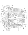
【課題】主流とは別に冷却空気として外気を吸入する構造を備えた遠心流体機械及び遠心送風機及び遠心圧縮機を提供する。【解決手段】回転軸8に軸着されたインペラ2と、前記回転軸に軸着され、前記インペラの背面側に設けられた冷却ファン34と、前記回転軸を介し前記インペラ及び前記冷却ファンを一体に回転させる回転駆動部4と、前記インペラを収納するインペラハウジング3と、該インペラハウジングに連結され、前記回転駆動部を収納するモータハウジング5とを具備し、該モータハウジングに吸気口14と排気口25が形成され、前記冷却ファンにより外気を前記吸気口より吸入し、前記外気が前記モータハウジング内を流通し、前記排気口より排気される様冷却流路が形成された。【選択図】図1PROBLEM TO BE SOLVED: To provide a centrifugal fluid machine, a centrifugal blower and a centrifugal compressor having a structure for sucking outside air as cooling air separately from the mainstream. SOLUTION: An impeller 2 pivotally attached to a rotating shaft 8, a cooling fan 34 axially attached to the rotating shaft and provided on the back side of the impeller, and the impeller and the cooling fan via the rotating shaft. A rotation drive unit 4 that is integrally rotated, an impeller housing 3 that houses the impeller, and a motor housing 5 that is connected to the impeller housing and stores the rotation drive unit are provided. An exhaust port 25 is formed, and a cooling flow path is formed so that the outside air is sucked from the intake port by the cooling fan, the outside air flows through the motor housing, and is exhausted from the exhaust port. [Selection diagram] Fig. 1
Description
本発明は、内部の発熱部品を冷却可能とした遠心流体機械及び遠心送風機及び遠心圧縮機に関するものである。 The present invention relates to a centrifugal fluid machine, a centrifugal blower, and a centrifugal compressor that can cool an internal heat generating component.
遠心式の送風機や圧縮機は、モータによりインペラを高速回転させ、インペラの回転により主流を吸入し、外部へと排気するものである。送風機や圧縮機の運転中、モータは発熱する。モータの温度が上昇すると、モータの回転効率が低下し、送風機や圧縮機の運用効率が低下すると共に、部品の材質も制限される為、モータを冷却する必要がある。 Centrifugal blowers and compressors rotate an impeller at high speed by a motor, suck the mainstream by the rotation of the impeller, and exhaust it to the outside. During operation of the blower or compressor, the motor generates heat. When the temperature of the motor rises, the rotational efficiency of the motor decreases, the operational efficiency of the blower and the compressor decreases, and the material of the parts is limited. Therefore, it is necessary to cool the motor.
モータを冷却する手段としては、従来、例えば主流又は主流の一部を冷却空気として用いるものがあった。従来の手段では、インペラの回転により主流を吸入し、外部へと排気する過程で、主流又は主流の一部をモータの周囲に流通させ、モータの冷却を行っていた。 Conventionally, as a means for cooling the motor, for example, there has been one using a mainstream or a part of the mainstream as cooling air. In the conventional means, in the process of sucking the main flow by the rotation of the impeller and exhausting it to the outside, the main flow or a part of the main flow is circulated around the motor to cool the motor.
尚、特許文献1には、ファンケースの導風口から空気が取入れられ、空気はファンの羽根部に案内されつつ、ディフューザからモータケースの内部に送り込まれ、モータの回転子鉄心の絶縁スロットの周囲等を通り抜け冷却した後、モータケースの外部へと排気される構成が開示されている。
In
然し乍ら、主流や主流の一部を冷却空気として用いる場合、主流自体が外気等モータを冷却可能な温度である必要があり、主流の温度が高い場合には主流や主流の一部を冷却空気として用いることができなかった。 However, when the mainstream or part of the mainstream is used as cooling air, the mainstream itself must be at a temperature that can cool the motor, such as outside air, and when the mainstream temperature is high, the mainstream or part of the mainstream is used as cooling air. It could not be used.
本発明は、主流とは別に冷却空気として外気を吸入する構造を備えた遠心流体機械及び遠心送風機及び遠心圧縮機を提供するものである。 The present invention provides a centrifugal fluid machine, a centrifugal blower, and a centrifugal compressor having a structure for sucking outside air as cooling air separately from the main stream.
本発明は、回転軸に軸着されたインペラと、前記回転軸に軸着され、前記インペラの背面側に設けられた冷却ファンと、前記回転軸を介し前記インペラ及び前記冷却ファンを一体に回転させる回転駆動部と、前記インペラを収納するインペラハウジングと、該インペラハウジングに連結され、前記回転駆動部を収納するモータハウジングとを具備し、該モータハウジングに吸気口と排気口が形成され、前記冷却ファンにより外気を前記吸気口より吸入し、前記外気が前記モータハウジング内を流通し、前記排気口より排気される様冷却流路が形成された遠心流体機械に係るものである。 The present invention includes an impeller that is pivotally mounted on a rotating shaft, a cooling fan that is pivotally mounted on the rotating shaft and provided on the back side of the impeller, and the impeller and the cooling fan rotate integrally through the rotating shaft. A rotation drive unit for driving, an impeller housing for storing the impeller, and a motor housing connected to the impeller housing for storing the rotation drive unit, wherein the motor housing has an intake port and an exhaust port, The present invention relates to a centrifugal fluid machine in which a cooling flow path is formed so that outside air is sucked from the intake port by a cooling fan, and the outside air flows through the motor housing and is exhausted from the exhaust port.
又本発明は、前記モータハウジングの一端部に前記回転軸との間に前記排気口を形成する流路形成板が設けられ、前記排気口に前記冷却ファンが設けられた遠心流体機械に係るものである。 The present invention also relates to a centrifugal fluid machine in which a flow path forming plate for forming the exhaust port is provided between one end portion of the motor housing and the rotating shaft, and the cooling fan is provided in the exhaust port. It is.
更に又本発明は、前記流路形成板と前記インペラハウジングとの間に排気流路が形成され、前記モータハウジング内の外気は前記流路形成板に偏向され、前記排気口より前記冷却ファンに吸入され、前記排気流路を通って外部に排気される遠心流体機械に係るものである。 Furthermore, in the present invention, an exhaust flow path is formed between the flow path forming plate and the impeller housing, and the outside air in the motor housing is deflected to the flow path forming plate, and is sent from the exhaust port to the cooling fan. The centrifugal fluid machine is sucked and exhausted to the outside through the exhaust passage.
本発明によれば、使用される主流が高温であった場合でも、前記回転駆動部を冷却することができるので、該回転駆動部の回転効率の低下が抑制され、運用効率の向上が図れると共に、部品の材質の自由度を高めることができるという優れた効果を発揮する。 According to the present invention, the rotation drive unit can be cooled even when the mainstream used is at a high temperature, so that a reduction in the rotation efficiency of the rotation drive unit is suppressed, and the operation efficiency can be improved. The excellent effect that the degree of freedom of the material of the part can be enhanced is exhibited.
以下、図面を参照しつつ本発明の実施例を説明する。 Embodiments of the present invention will be described below with reference to the drawings.
先ず、図1〜図3に於いて、本発明の実施例に係る遠心流体機械について説明する。尚、図1中、紙面に対して左側を先端側、紙面に対して右側を基端側とする。又、本実施例では、遠心送風機を例に取って説明する。 First, a centrifugal fluid machine according to an embodiment of the present invention will be described with reference to FIGS. In FIG. 1, the left side with respect to the paper surface is the front end side, and the right side with respect to the paper surface is the base end side. In this embodiment, a centrifugal blower will be described as an example.
送風機1は、インペラ2が収納されたインペラハウジング3と、前記インペラ2を回転させる回転駆動部である電磁コイル4が収納されたモータハウジング5を有している。
The
該モータハウジング5は円筒状のモータハウジング本体部6を有し、該モータハウジング本体部6の周面には放熱フィン7が形成されている。又、前記モータハウジング本体部6には、例えばステンレス製の回転軸8が前記モータハウジング5と同心に挿通されている。
The
前記回転軸8にはロータ8aが形成され、該ロータ8aの周囲を僅かな間隙をもって囲繞する様に前記電磁コイル4が設けられている。図示しない配線を介して前記電磁コイル4に通電させることで、該電磁コイル4と前記ロータ8aとの間に回転磁界を生じさせ、前記ロータ8aを回転させる様になっている。
A
前記電磁コイル4と前記ロータ8aとの間、及び前記電磁コイル4と前記モータハウジング本体部6の内周面との間には、回転に支障のない程度の隙間が形成されている。又、該モータハウジング本体部6の内周面には、軸心方向全長に亘って形成された溝9が、所定角度ピッチ、例えば60°ピッチで全周に亘って形成されている。
A gap is formed between the
前記回転軸8の前記ロータ8aより基端側に突出する部位には、基端側軸受部11が設けられ、該基端側軸受部11により前記回転軸8が回転自在に支持されている。該基端側軸受部11は径方向に突出するフランジ部11aを有し、該フランジ部11aを介して後述する基端側軸受板12とボルト等により固着されることで、前記基端側軸受部11の軸方向、径方向の変位が拘束される様になっている。
A base end
前記基端側軸受板12は、前記モータハウジング本体部6の基端部にボルト等で固着される。又、前記基端側軸受板12には、所定の角度ピッチで複数の吸気口14が形成されている。該吸気口14を介して、外部と前記モータハウジング本体部6の内部とが連通される。尚、前記吸気口14には、外部から前記モータハウジング本体部6の内部に異物が侵入しない様、防塵フィルタ等のフィルタ(図示せず)が設けられてもよい。
The base end
前記回転軸8の前記ロータ8aより先端側に突出する部位には、先端側軸受部18が設けられ、該先端側軸受部18により前記回転軸8が回転自在に支持されている。前記先端側軸受部18は径方向に突出するフランジ部18aを有し、該フランジ部18aを介して後述する先端側軸受板19とボルト等により固着されることで、前記先端側軸受部18の軸方向、径方向の変位が拘束される様になっている。
A tip-side bearing
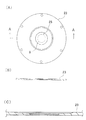
前記先端側軸受板19は、前記モータハウジング本体部6の先端部に、ボルト等により固着される。又、前記モータハウジング本体部6の先端部の前記先端側軸受板19よりも更に先端側には、図2(A)に示される様な、第1のプレートである流路形成板23がボルト等により固着される。前記先端側軸受板19と前記流路形成板23との間には所定の間隔の空間24が形成される。
The front end
尚、前記モータハウジング本体部6、前記基端側軸受板12、前記先端側軸受板19、前記流路形成板23等により、前記モータハウジング5が構成される。
The
前記先端側軸受部18と前記基端側軸受部11とにより、前記回転軸8が回転自在に支持されると共に、軸方向、径方向の変位が拘束される。
The
前記先端側軸受板19の周囲には、所定の角度ピッチで複数の流通口20が形成されている。該流通口20を介して、前記モータハウジング本体部6の内部と前記空間24とが連通される。
Around the front end
図2(B)、図2(C)に示す様に、前記流路形成板23は、中心部に孔が穿設された円板状となっている。該孔の径は前記回転軸8の径よりも大きくなっており、前記流路形成板23を前記モータハウジング本体部6に取付けた際には、前記流路形成板23と前記回転軸8との間にリング状の排気口25が形成される。前記溝9、前記空間24等により、前記モータハウジング5内に前記吸気口14から前記排気口25に至る冷却流路が形成される。
As shown in FIGS. 2 (B) and 2 (C), the flow
前記インペラハウジング3は、インペラハウジング本体部26と、第2のプレートであり中心部に孔が穿設された略円板状の閉塞板27とを有している。
The
前記インペラハウジング本体部26と前記閉塞板27とは、Oリング等の気密部材28を挾んでボルト等により固着される。前記閉塞板27と固着されることで、前記インペラハウジング本体部26は基端面が閉塞され、内部にディフューザ29やスクロール31等、前記インペラ2により吸入され、排気される主流32の流路が形成される。又、前記回転軸8が、前記閉塞板27の孔を貫通して前記インペラハウジング3に延出している。
The
尚、前記閉塞板27には、所定の角度ピッチで基端側に突出するネジ座部(図示せず)と、外周縁部で基端側に向って傾斜する傾斜部27aが形成されている。前記ネジ座部を介して前記閉塞板27と前記モータハウジング本体部6とがボルト等で固着され、或は前記流路形成板23を前記ネジ座部と前記モータハウジング本体部6で挾んだ状態で、前記閉塞板27と前記モータハウジング本体部6とがボルト等で固着される。前記インペラハウジング3と前記モータハウジング5とは、前記閉塞板27を介在した状態で連結される。
The
この時、前記流路形成板23と前記閉塞板27との間には排気流路33が形成される。該排気流路33は、前記排気口25を介して前記モータハウジング5内と連通すると共に、前記送風機1の外部と連通している。
At this time, an
前記回転軸8の前記流路形成板23よりも先端側には先端側中径部8dが形成され、該先端側中径部8dには例えばアルミニウム製の冷却ファン34が嵌入され軸着されている。又、前記先端側中径部8dの先端側には先端側小径部8eが形成され、該先端側小径部8eには例えばアルミニウム製の前記インペラ2が嵌入され軸着されている。
A tip-side
該インペラ2の中心部には、基端側に、即ち背面方向に突出するボス部2aが形成され、該ボス部2aは前記閉塞板27を貫通している。前記ボス部2aの軸心方向の長さは前記閉塞板27の孔の軸心方向の長さと略一致するか、僅かに長くなっている。
A
前記冷却ファン34は前記排気流路33内、即ち前記排気口25に対向して設けられ、前記冷却ファン34の径は、前記排気口25の径よりも大きくなっている。
The cooling
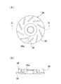
又、前記冷却ファン34は、図3(A)、図3(B)に示される様に、底板35の表面(図1中基端側面)に所定の角度ピッチで複数枚、例えば10枚の羽根36が設けられた羽根車であり、中心部から吸入した流体を外径方向へと排気する様になっている。又、前記底板35の中心部には、流体を吸入する側、即ち基端側に突出する円柱状のボス部35aが形成され、該ボス部35aが前記先端側中径部8dと嵌合する。従って、前記冷却ファン34及び前記インペラ2と前記回転軸8とが一体に回転する。
Further, as shown in FIGS. 3 (A) and 3 (B), the cooling
この時、前記冷却ファン34が前記インペラ2の背面に密着するが、前記ボス部2aにより前記インペラ2と前記冷却ファン34との間には隙間が形成され、該隙間に前記閉塞板27が位置し、前記インペラ2と前記冷却ファン34との間が前記閉塞板27により仕切られる様になっている。
At this time, although the cooling
次に、前記送風機1の作動について説明する。
Next, the operation of the
図示しない配線より前記電磁コイル4に電力が供給されると、該電磁コイル4と前記回転軸8の前記ロータ8aとの間に回転磁界が生じ、前記回転軸8が高速で回転する。
When electric power is supplied to the
該回転軸8の回転により前記インペラ2が一体に回転し、該インペラ2の回転により前記インペラハウジング3内に前記主流32が吸入される。該主流32は例えば90℃程度であり、前記インペラハウジング3内に吸入された前記主流32は、前記ディフューザ29、前記スクロール31を経て所定の送風対象物に対して送風される。
The
又、前記回転軸8の回転により前記冷却ファン34が一体に回転する。該冷却ファン34の回転により、前記排気口25より前記モータハウジング5内が吸引される。前記モータハウジング5内が負圧となり、前記吸気口14を介して前記モータハウジング5内に外気が冷却空気38として吸入される。
Further, the cooling
前記吸気口14より吸入された前記冷却空気38は、前記モータハウジング本体部6の内周面に形成された前記溝9を流通し、一部が前記電磁コイル4と前記ロータ8aとの間を流通する。
The cooling
前記モータハウジング本体部6内を流通した前記冷却空気38は、前記流通口20を経て前記空間24に到達すると、前記流路形成板23により中心方向へと偏向される。中心方向へと偏向された前記冷却空気38は、前記排気口25より前記モータハウジング5の外部へと排気される。
When the cooling
前記排気口25より排気され前記冷却ファン34に吸入された前記冷却空気38は、外径方向に排気され、前記排気流路33を流通し、前記傾斜部27aにガイドされて前記送風機1の外部へと排気される。
The cooling
該送風機1の運用中、前記電磁コイル4が発熱するが、該電磁コイル4は前記モータハウジング本体部6内を流通する前記冷却空気38により冷却され、更に外気と熱交換する前記放熱フィン7により冷却され、例えば150℃から100℃迄冷却することができる。
During operation of the
又、前記インペラハウジング3内に吸入された前記主流32は、前記閉塞板27と前記インペラ2の間から僅かに前記排気流路33内に流入するが、該排気流路33内に流入した前記主流32は前記冷却ファン34により前記冷却空気38と共に前記送風機1の外部へと排気されるので、前記主流32により前記電磁コイル4の冷却が妨げられることはない。
The
上述の様に、本実施例では、前記モータハウジング5に前記吸気口14と前記排気口25を設け、前記回転軸8により回転される前記冷却ファン34により、前記主流32とは別に、外気を前記冷却空気38として前記モータハウジング5内に吸入し、流通させ、排気している。
As described above, in this embodiment, the
従って、前記送風機1で使用される前記主流32が高温である場合であっても、前記電磁コイル4を冷却することができるので、該電磁コイル4の回転効率の低下が抑制され、前記送風機1の運用効率の向上が図れる。又、前記モータハウジング5等に用いられるさび止め等の高温による劣化を防止でき、部品の材質の自由度を高めることができる。
Therefore, even when the mainstream 32 used in the
又、前記冷却ファン34は前記回転軸8に設けられ、前記インペラ2と一体に回転する様になっているので、前記冷却ファン34を回転させる為のモータを別途設ける必要がなく、前記送風機1の製作コストの低減、装置の小型化を図ることができる。
Further, since the cooling
又、前記インペラハウジング3と前記モータハウジング5の間に第1のプレートである前記流路形成板23を設け、該流路形成板23と前記回転軸8との間に排気口25を設け、該排気口25に対向して前記冷却ファン34を設けているので、前記冷却ファン34を大型化することなく確実に前記冷却空気38を前記モータハウジング5外へと排気することができる。
Further, the flow
又、前記流路形成板23と前記インペラハウジング3の前記閉塞板27との間に前記排気流路33が形成され、前記流路形成板23により前記冷却ファン34で吸排される前記冷却空気38の流路が分離される。従って、前記冷却ファン34で吸入される前記冷却空気38と排気される該冷却空気38とが干渉することがないので、該冷却空気38の排気効率を向上させることができ、前記電磁コイル4の冷却効率を向上させることができる。
The
又、前記排気流路33を形成したことで、前記インペラハウジング3から高温の前記主流32が流入した場合でも、前記冷却ファン34により前記冷却空気38と共に前記送風機1の外部へと排気されるので、前記主流32が前記モータハウジング5内に流入するのを防止することができる。
Further, since the
尚、本実施例では、前記冷却ファン34が前記冷却空気38を中心部から吸入し、外径方向に排気する遠心ファンとしているが、前記冷却ファン34を前記排気口25内に設けられた軸流ファンとしてもよいし、他の形式のファンを用いてもよい。
In this embodiment, the cooling
又、本実施例では、前記送風機1を例として前記電磁コイル4の冷却構造を説明したが、該冷却構造は遠心圧縮機に対しても適用可能であるのは言う迄もない。
In the present embodiment, the cooling structure of the
1 送風機 2 インペラ
3 インペラハウジング 4 電磁コイル
5 モータハウジング 8 回転軸
14 吸気口 23 流路形成板
24 空間 25 排気口
32 主流 33 排気流路
34 冷却ファン 38 冷却空気
DESCRIPTION OF
Claims (5)
Priority Applications (1)
| Application Number | Priority Date | Filing Date | Title |
|---|---|---|---|
| JP2016049641A JP6786823B2 (en) | 2016-03-14 | 2016-03-14 | Centrifugal fluid machine, centrifugal blower and centrifugal compressor |
Applications Claiming Priority (1)
| Application Number | Priority Date | Filing Date | Title |
|---|---|---|---|
| JP2016049641A JP6786823B2 (en) | 2016-03-14 | 2016-03-14 | Centrifugal fluid machine, centrifugal blower and centrifugal compressor |
Publications (2)
| Publication Number | Publication Date |
|---|---|
| JP2017166330A true JP2017166330A (en) | 2017-09-21 |
| JP6786823B2 JP6786823B2 (en) | 2020-11-18 |
Family
ID=59909889
Family Applications (1)
| Application Number | Title | Priority Date | Filing Date |
|---|---|---|---|
| JP2016049641A Active JP6786823B2 (en) | 2016-03-14 | 2016-03-14 | Centrifugal fluid machine, centrifugal blower and centrifugal compressor |
Country Status (1)
| Country | Link |
|---|---|
| JP (1) | JP6786823B2 (en) |
Cited By (8)
| Publication number | Priority date | Publication date | Assignee | Title |
|---|---|---|---|---|
| WO2019049202A1 (en) * | 2017-09-05 | 2019-03-14 | 株式会社Ihi | Fluid machine |
| JP2020067019A (en) * | 2018-10-23 | 2020-04-30 | 株式会社Ihi | Fluid machine |
| JP2020103012A (en) * | 2018-12-25 | 2020-07-02 | ダイハツ工業株式会社 | vehicle |
| WO2021210097A1 (en) | 2020-04-15 | 2021-10-21 | 株式会社Ihi | Fluid machine |
| CN115788967A (en) * | 2023-02-10 | 2023-03-14 | 鸿陆智能科技(山东)有限公司 | Heat dissipation channel of magnetic suspension air blower |
| KR102556944B1 (en) * | 2023-02-03 | 2023-07-19 | 한국터보기술 주식회사 | Turbo blower with increased motor efficiency |
| CN116771693A (en) * | 2022-03-15 | 2023-09-19 | 株式会社丰田自动织机 | centrifugal compressor |
| KR102603139B1 (en) * | 2023-04-06 | 2023-11-20 | 주식회사 성광이엔에프 | Mechanical Vapor Recompression System with heat pipe combined cooling module |
Citations (8)
| Publication number | Priority date | Publication date | Assignee | Title |
|---|---|---|---|---|
| JPS5168003U (en) * | 1974-11-26 | 1976-05-29 | ||
| JPS58106599U (en) * | 1982-01-14 | 1983-07-20 | 株式会社日立製作所 | electric pump |
| JPS58138295A (en) * | 1982-02-12 | 1983-08-17 | Hitachi Ltd | pump |
| JPH02207199A (en) * | 1989-02-03 | 1990-08-16 | Tokyo Gas Co Ltd | Shaft section cooling mechanism for ceramic fan |
| JPH08277800A (en) * | 1995-04-05 | 1996-10-22 | Toho Eng Kk | Centrifugal blower |
| JPH0998913A (en) * | 1995-07-31 | 1997-04-15 | Tokyo Cosmos Electric Co Ltd | Reflux and suction type vacuum cleaners |
| JP2001515991A (en) * | 1997-09-10 | 2001-09-25 | ターボダイン システムズ インコーポレイテッド | Motor driven centrifugal compressor with internal cooling air |
| US20090291004A1 (en) * | 2006-12-18 | 2009-11-26 | Airfan | Fan for an apparatus for the regulated delivery of a gas, in particular oxygen |
-
2016
- 2016-03-14 JP JP2016049641A patent/JP6786823B2/en active Active
Patent Citations (8)
| Publication number | Priority date | Publication date | Assignee | Title |
|---|---|---|---|---|
| JPS5168003U (en) * | 1974-11-26 | 1976-05-29 | ||
| JPS58106599U (en) * | 1982-01-14 | 1983-07-20 | 株式会社日立製作所 | electric pump |
| JPS58138295A (en) * | 1982-02-12 | 1983-08-17 | Hitachi Ltd | pump |
| JPH02207199A (en) * | 1989-02-03 | 1990-08-16 | Tokyo Gas Co Ltd | Shaft section cooling mechanism for ceramic fan |
| JPH08277800A (en) * | 1995-04-05 | 1996-10-22 | Toho Eng Kk | Centrifugal blower |
| JPH0998913A (en) * | 1995-07-31 | 1997-04-15 | Tokyo Cosmos Electric Co Ltd | Reflux and suction type vacuum cleaners |
| JP2001515991A (en) * | 1997-09-10 | 2001-09-25 | ターボダイン システムズ インコーポレイテッド | Motor driven centrifugal compressor with internal cooling air |
| US20090291004A1 (en) * | 2006-12-18 | 2009-11-26 | Airfan | Fan for an apparatus for the regulated delivery of a gas, in particular oxygen |
Cited By (12)
| Publication number | Priority date | Publication date | Assignee | Title |
|---|---|---|---|---|
| WO2019049202A1 (en) * | 2017-09-05 | 2019-03-14 | 株式会社Ihi | Fluid machine |
| US11261879B2 (en) | 2017-09-05 | 2022-03-01 | Ihi Corporation | Fluid machine |
| JP2020067019A (en) * | 2018-10-23 | 2020-04-30 | 株式会社Ihi | Fluid machine |
| JP7353742B2 (en) | 2018-10-23 | 2023-10-02 | 株式会社Ihi | fluid machinery |
| JP2020103012A (en) * | 2018-12-25 | 2020-07-02 | ダイハツ工業株式会社 | vehicle |
| JP7336189B2 (en) | 2018-12-25 | 2023-08-31 | ダイハツ工業株式会社 | vehicle |
| WO2021210097A1 (en) | 2020-04-15 | 2021-10-21 | 株式会社Ihi | Fluid machine |
| US12292057B2 (en) | 2020-04-15 | 2025-05-06 | Ihi Corporation | Fluid machine |
| CN116771693A (en) * | 2022-03-15 | 2023-09-19 | 株式会社丰田自动织机 | centrifugal compressor |
| KR102556944B1 (en) * | 2023-02-03 | 2023-07-19 | 한국터보기술 주식회사 | Turbo blower with increased motor efficiency |
| CN115788967A (en) * | 2023-02-10 | 2023-03-14 | 鸿陆智能科技(山东)有限公司 | Heat dissipation channel of magnetic suspension air blower |
| KR102603139B1 (en) * | 2023-04-06 | 2023-11-20 | 주식회사 성광이엔에프 | Mechanical Vapor Recompression System with heat pipe combined cooling module |
Also Published As
| Publication number | Publication date |
|---|---|
| JP6786823B2 (en) | 2020-11-18 |
Similar Documents
| Publication | Publication Date | Title |
|---|---|---|
| JP2017166330A (en) | Centrifugal fluid machine, centrifugal blower, and centrifugal compressor | |
| JP7042265B2 (en) | Turbo compressor with separate cooling air passages | |
| US11261879B2 (en) | Fluid machine | |
| JP7491352B2 (en) | Fluid Machinery | |
| EP3438461A1 (en) | Electric fan and electric vacuum cleaner equipped with same | |
| WO2013176028A1 (en) | Vacuum pump | |
| KR101563314B1 (en) | Open type motor | |
| WO2018011970A1 (en) | Motor-integrated fluid machine | |
| EP4098887B1 (en) | Fluid machine | |
| DK2591542T3 (en) | Electric machine | |
| US11578658B2 (en) | High-speed turbo machine enabling cooling thermal equilibrium | |
| US11339791B2 (en) | High-speed dual turbo machine enabling cooling thermal equilibrium | |
| US11454246B2 (en) | Electric blower, vacuum cleaner, and hand drying device | |
| KR101164588B1 (en) | Turbo compressor | |
| CN111520339B (en) | A high-speed electric motor driven centrifugal compressor and blower | |
| KR100437037B1 (en) | Centrifugal fan of vacuum cleaner | |
| JPH07213018A (en) | An external fan device for a totally enclosed external fan-type rotating electric machine | |
| KR101856739B1 (en) | Cooling fan apparatus for vehicle provided with preventing function of foreign matter entrance | |
| CN117553020A (en) | Durable magnetic suspension blower | |
| KR20170000521U (en) | Ring blower having front colling fan | |
| JPH0536208U (en) | Cooling system |
Legal Events
| Date | Code | Title | Description |
|---|---|---|---|
| A621 | Written request for application examination |
Free format text: JAPANESE INTERMEDIATE CODE: A621 Effective date: 20190125 |
|
| A131 | Notification of reasons for refusal |
Free format text: JAPANESE INTERMEDIATE CODE: A131 Effective date: 20191029 |
|
| A977 | Report on retrieval |
Free format text: JAPANESE INTERMEDIATE CODE: A971007 Effective date: 20191031 |
|
| A521 | Request for written amendment filed |
Free format text: JAPANESE INTERMEDIATE CODE: A523 Effective date: 20191225 |
|
| A131 | Notification of reasons for refusal |
Free format text: JAPANESE INTERMEDIATE CODE: A131 Effective date: 20200407 |
|
| A521 | Request for written amendment filed |
Free format text: JAPANESE INTERMEDIATE CODE: A523 Effective date: 20200521 |
|
| TRDD | Decision of grant or rejection written | ||
| A01 | Written decision to grant a patent or to grant a registration (utility model) |
Free format text: JAPANESE INTERMEDIATE CODE: A01 Effective date: 20200929 |
|
| A61 | First payment of annual fees (during grant procedure) |
Free format text: JAPANESE INTERMEDIATE CODE: A61 Effective date: 20201012 |
|
| R151 | Written notification of patent or utility model registration |
Ref document number: 6786823 Country of ref document: JP Free format text: JAPANESE INTERMEDIATE CODE: R151 |