WO2019044740A1 - 制御システム及び制御方法 - Google Patents
制御システム及び制御方法 Download PDFInfo
- Publication number
- WO2019044740A1 WO2019044740A1 PCT/JP2018/031500 JP2018031500W WO2019044740A1 WO 2019044740 A1 WO2019044740 A1 WO 2019044740A1 JP 2018031500 W JP2018031500 W JP 2018031500W WO 2019044740 A1 WO2019044740 A1 WO 2019044740A1
- Authority
- WO
- WIPO (PCT)
- Prior art keywords
- valve
- compressor
- pressure
- throttle valve
- downstream
- Prior art date
- Legal status (The legal status is an assumption and is not a legal conclusion. Google has not performed a legal analysis and makes no representation as to the accuracy of the status listed.)
- Ceased
Links
Images


Classifications
-
- F—MECHANICAL ENGINEERING; LIGHTING; HEATING; WEAPONS; BLASTING
- F02—COMBUSTION ENGINES; HOT-GAS OR COMBUSTION-PRODUCT ENGINE PLANTS
- F02B—INTERNAL-COMBUSTION PISTON ENGINES; COMBUSTION ENGINES IN GENERAL
- F02B37/00—Engines characterised by provision of pumps driven at least for part of the time by exhaust
- F02B37/12—Control of the pumps
-
- F—MECHANICAL ENGINEERING; LIGHTING; HEATING; WEAPONS; BLASTING
- F02—COMBUSTION ENGINES; HOT-GAS OR COMBUSTION-PRODUCT ENGINE PLANTS
- F02B—INTERNAL-COMBUSTION PISTON ENGINES; COMBUSTION ENGINES IN GENERAL
- F02B37/00—Engines characterised by provision of pumps driven at least for part of the time by exhaust
- F02B37/12—Control of the pumps
- F02B37/16—Control of the pumps by bypassing charging air
-
- Y—GENERAL TAGGING OF NEW TECHNOLOGICAL DEVELOPMENTS; GENERAL TAGGING OF CROSS-SECTIONAL TECHNOLOGIES SPANNING OVER SEVERAL SECTIONS OF THE IPC; TECHNICAL SUBJECTS COVERED BY FORMER USPC CROSS-REFERENCE ART COLLECTIONS [XRACs] AND DIGESTS
- Y02—TECHNOLOGIES OR APPLICATIONS FOR MITIGATION OR ADAPTATION AGAINST CLIMATE CHANGE
- Y02T—CLIMATE CHANGE MITIGATION TECHNOLOGIES RELATED TO TRANSPORTATION
- Y02T10/00—Road transport of goods or passengers
- Y02T10/10—Internal combustion engine [ICE] based vehicles
- Y02T10/12—Improving ICE efficiencies
Definitions
- the present disclosure relates to a control system and control method, and more particularly, to a control system for a turbocharged internal combustion engine having a throttle valve downstream of a compressor of a turbocharger, and in communication with the throttle valve upstream and compressor downstream thereof.
- the present invention relates to a control method of a valve provided in a passage.
- turbocharger to improve the flowability of intake air.
- This type of turbocharged engine may cause a so-called surge phenomenon in which the intake air intermittently flows back from the outlet side to the inlet side of the compressor by improving the flowability of the intake air.
- Such a surge phenomenon is closely related to the balance between the pressure ratio and the intake flow rate in the compressor, and occurs as the intake flow rate decreases and the ratio (pressure ratio) of the outlet pressure to the inlet pressure of the compressor increases. It is known to be easy to do.
- a surge region where such a surge phenomenon occurs is represented, for example, in a compressor performance curve or the like in which the intake flow rate is taken on the horizontal axis and the pressure ratio is taken on the vertical axis.
- Patent Document 1 discloses that the air bypass valve is opened when the internal pressure of the surge tank downstream of the throttle valve downstream of the turbocharger compressor is lower than a predetermined value.
- the predetermined value is a limit value of the pressure in the surge tank at which a surge phenomenon may occur in the compressor.
- noise may be generated from the intake system. It is known that the noise from the intake system is generated particularly in an engine that operates a compressor in an operating range where the size of the turbocharger is large and the performance limit of the turbocharger is mainly about half.
- Abnormal noise that occurs when the compressor operates in an area other than the surge area occurs when the throttle valve is suddenly closed while the pressure in the intake passage downstream of the compressor is high. There are many. Such abnormal noise may cause the driver to feel uncomfortable.
- An object of the present disclosure is to provide a control system and control method capable of more preferably preventing abnormal noise that may occur when a compressor of a turbocharger is operating in a non-surge region in a turbocharged internal combustion engine. It is.
- a control system for a turbocharged internal combustion engine comprising a throttle valve downstream of a turbocharger compressor, comprising: A relief passage in communication with an intake passage portion upstream of the throttle valve and downstream of the compressor; A valve for adjusting the open state of the escape passage; A control unit for controlling the operation of the valve; The control unit operates when the compressor is in a non-surge region other than a surge region and the pressure in the intake passage downstream of the compressor when the throttle valve is closed is less than a predetermined pressure.
- the valve is closed when the valve is closed, the compressor is in operation in the non-surge region, and the pressure in the intake passage downstream of the compressor when the throttle valve is closed is equal to or higher than the predetermined pressure Control the operation of the valve to open the
- downstream end of the relief passage is in communication with the intake passage portion on the upstream side of the compressor.
- control unit The valve is opened when the pressure in the intake passage downstream of the compressor when the compressor is in the non-surge region and the throttle valve is closed is equal to or higher than a first predetermined pressure, and then The operation of the valve is controlled to close the valve when the pressure downstream of the compressor and upstream of the throttle valve becomes less than a second predetermined pressure.
- the control method of the present disclosure is A relief passage provided with a throttle valve on the downstream side of the compressor of the turbocharger and in communication with an intake passage upstream of the throttle valve and on the downstream side of the compressor, and a valve for adjusting the open state of the relief passage And controlling the valve in a turbocharged internal combustion engine, further comprising: A determination step of determining whether the pressure in the intake passage downstream of the compressor when the throttle valve is closed when the compressor is in a non-surge region other than a surge region; , When the pressure in the intake passage downstream of the compressor when the throttle valve is closed is determined to be equal to or higher than the predetermined pressure in the determination step, the valve in the closed state is opened. And controlling the operation.
- the pressure in the intake passage downstream of the compressor when the compressor is in the non-surge region and the throttle valve is closed.
- the valve related to the release passage is closed, and when the pressure is equal to or more than the predetermined pressure, the valve is opened. Therefore, in the turbocharged engine, noise that may occur when the compressor of the turbocharger is operating in the non-surge region can be more preferably prevented.
- FIG. 1 is a schematic configuration diagram of a turbocharged internal combustion engine to which a control system according to an embodiment of the present disclosure is applied.
- FIG. 2 is a flowchart in an embodiment of the present disclosure.
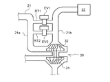
- FIG. 3 is a view for explaining a modification of the embodiment of FIG.
- FIG. 1 is a schematic overall configuration diagram showing an internal combustion engine 10 according to the present embodiment.
- the internal combustion engine 10 here is a diesel engine, and will be hereinafter referred to simply as an engine, but may be a gasoline engine, a CNG engine or the like, and the present disclosure does not intend to specifically limit the type of engine to which it is applied. .
- the cylinder head 11 of the engine 10 is provided with an intake port 11A for introducing intake air into the cylinder C and an exhaust port 11B for extracting exhaust gas from the cylinder C. Further, the cylinder head 11 is provided with an intake valve 12 and an exhaust valve 14 which are opened and closed by a valve mechanism (not shown). Furthermore, the cylinder head 11 is provided with an injector 15 for directly injecting fuel into the cylinder C. The fuel injection amount and injection timing of the injector 15 are controlled according to a signal input from an electronic control unit (hereinafter referred to as an ECU) 100.
- an ECU electronice control unit
- a cylinder block 16 is provided below the cylinder head 11, and an oil pan 17 for storing engine oil is provided below the crankcase portion 16A of the cylinder block 16.
- a piston P is accommodated in the cylinder C of the cylinder block 16 so as to be capable of reciprocating.
- a piston ring PR which is in sliding contact with the inner wall of the cylinder C is mounted. Further, a crankshaft CS is connected to the piston P via a connecting rod CR. 1 shows only one cylinder among a plurality of cylinders of the engine 10, and illustration of the other cylinders is omitted.
- the engine 10 may be any of a plurality of cylinders or a single cylinder.
- An intake manifold 20 communicating with the intake port 11A is provided on the side of the cylinder head 11 on the intake side.
- An intake passage 21 for introducing intake air is connected to the intake manifold 20.
- the air cleaner 22, intake air flow sensor (MAF sensor) 92, compressor 32 of the turbocharger 30, intercooler 23, intake temperature sensor 93, throttle valve THV, boost pressure sensor (intake A pressure sensor) 94 or the like is provided.
- the intake air temperature sensor 93 is provided on the upstream side of the throttle valve THV, but may be provided on the downstream side of the throttle valve THV.
- An exhaust manifold 24 communicating with the exhaust port 11B is provided on the side of the cylinder head 11 on the exhaust side.
- the exhaust manifold 24 is connected to an exhaust passage 25 for leading the exhaust gas to the atmosphere.
- an exhaust temperature sensor 95, a turbine 31 of the turbocharger 30, an exhaust purification device 40 and the like are provided in this order from the exhaust upstream side.
- the turbocharger 30 includes the above-described turbine 31 driven by the exhaust, and the above-described compressor 32 coupled to the turbine 31 by a rotating shaft and pumping the intake air.
- the turbocharger 30 is not limited to the conventional type illustrated in the illustrated example, and may be a variable displacement type including variable wings.
- a relief passage RT in communication with the intake passage portion 21a upstream of the throttle valve THV and downstream of the compressor 32 is provided.
- One end (upstream end) of the escape passage RT is in communication with the intake passage portion 21a, in particular, the upstream side of the intercooler 23.
- one end of the release passage RT may be in communication with the downstream side of the intercooler 23 in the intake passage portion 21a.
- the other end (downstream end) of the relief passage RT is in communication with the intake passage portion 21b on the upstream side (and the downstream side of the air cleaner 22) of the compressor 32. Therefore, the escape passage RT is a bypass passage that bypasses the compressor 32.
- the relief passage RT is provided with a valve (which may be referred to as a bypass valve) EV for adjusting its open state.
- the valve EV is a solenoid control valve, the operation of which is controlled based on a signal (to the actuator of the valve EV) from the ECU 100. Therefore, the ECU 100 has a function as control means for controlling the operation of the valve EV.
- the ECU 100 performs various controls of the engine 10 and the like, and includes a known arithmetic processing unit (for example, a CPU), a storage device (for example, a ROM, a RAM), an input port, an output port, and the like.
- a known arithmetic processing unit for example, a CPU
- a storage device for example, a ROM, a RAM
- An intake air flow sensor 92, an intake temperature sensor 93, a boost pressure sensor 94, and an exhaust temperature sensor 95 are electrically connected to the ECU 100, and an engine rotational speed sensor 90 and an accelerator opening sensor 91 are electrically connected. It is connected, and the output signal from those sensors etc. is inputted.
- An intake pressure sensor may be further provided for detecting (acquiring) the pressure of intake air in the intake passage upstream of the compressor, and the intake air may be provided downstream of the intercooler 23 and upstream of the throttle valve THV.
- An intake pressure sensor may be further provided to detect (acquire) the pressure of The ECU 100 acquires the engine rotation speed based on the output of the engine rotation speed sensor 90, and acquires the accelerator opening based on the output of the accelerator opening sensor 91.
- the ECU 100 obtains the flow rate of the intake air introduced from the air cleaner 22 into the intake passage 21 based on the output of the intake air flow sensor 92, and based on the output of the intake temperature sensor 93, The temperature is acquired, and the pressure (supercharging pressure) of the intake air pressurized by the compressor 32 is acquired based on the output of the boost pressure sensor 94. Further, the ECU 100 obtains the temperature of the exhaust gas which is discharged from the engine 10 and flows through the exhaust passage on the upstream side of the turbine 31 based on the output of the exhaust temperature sensor 95.
- the ECU 100 acquires various values based on the output from the sensor etc., and performs calculations based on prestored programs and data, and the injector 15, the throttle valve THV (the actuator), the valve EV (the actuator) Output an operation signal to each.
- the injector 15, the throttle valve THV, the valve EV and the like are controlled. Therefore, the ECU 100 has a function as a control means of each of them.
- engine 10 is usually operated such that the compressor of the turbocharger is operated (operated) in an area other than the surge area (non-surge area).
- the engine 10 is of the high displacement class and the compressor is of the large class.
- the surge region is a predetermined region in which a surge phenomenon can occur, and here, the other region is referred to as a "non-surge region".
- the throttle valve THV is closed, whereby the pressure or suction on the downstream side of the compressor 32 is There are times when the pressure increases. At this time, noise may be generated from the intake system of the engine 10 even though the operating region of the compressor does not enter the surge region.
- the pressure fluctuation generated in the intake passage in particular, the intake passage portion 21a upstream of the throttle valve THV and downstream of the compressor 32
- the high pressure downstream of the compressor can be mentioned based on the high pressure downstream of the compressor.
- the escape passage RT and the valve EV are provided, and when there is a possibility of occurrence of such abnormal noise, the opening degree of the escape passage RT, that is, the opening degree of the valve EV is controlled. It has been found that the noise can be prevented or suppressed.
- region is demonstrated based on the flowchart of FIG. However, the routine of FIG. 2 is repeated at predetermined time intervals.
- the control of the valve EV described below is based on the premise that the compressor is in an operating state in a non-surge region and the operating state of the compressor does not enter the surge region even when the throttle valve THV is closed.
- step S201 the ECU 100 determines whether the valve EV is in a closed state.
- the valve EV is normally closed.
- an affirmative determination is made in step S201.
- a negative determination is made in step S201.
- step S203 it is determined whether the throttle valve THV is driven to close.
- the ECU 100 sets the throttle to an opening corresponding to the accelerator opening detected (obtained) based on the depression amount of the accelerator pedal operated by the driver, that is, the output of the accelerator opening sensor 91. Control the opening degree of the valve THV. Then, the ECU 100 controls the opening degree of the throttle valve THV to the opening degree calculated based on the acquired accelerator opening degree or the like according to a program or the like determined in advance in consideration of fuel consumption and the like.
- step S203 When it is determined by the calculation of the opening degree control of the throttle valve THV that the ECU 100 is to close the throttle valve in the open state to full close (drive to close), the ECU 100 makes an affirmative determination in step S203.
- the throttle valve THV is not driven to close (that is, when the opening degree is controlled to be larger than the full closure), the ECU 100 makes a negative determination in step S203.
- step S205 it is determined whether the intake pressure is equal to or higher than a predetermined pressure.
- the intake pressure here is a pressure detected (obtained) based on the output of the boost pressure sensor 94, and is a supercharging pressure.
- the intake pressure to be determined in step S205 is the intake pressure downstream of the throttle valve THV
- the intake pressure downstream of the compressor 32 is the intake pressure upstream of the throttle valve THV. It may be Further, when the ECU 100 estimates the intake pressure downstream of the compressor 32 in the computation in the engine control, the estimated intake pressure may be adopted in step S205.
- the predetermined pressure is determined in advance based on experiments, and is set below the pressure limit value at which the abnormal noise may occur.
- an affirmative determination is made in step S205. If the intake pressure is less than the predetermined pressure, a negative determination is made in step S205.
- step S203 determines whether the throttle valve THV is not driven to close, or if the determination in step S205 is negative because the intake pressure is less than the predetermined pressure. If the determination in step S203 is negative because the throttle valve THV is not driven to close, or if the determination in step S205 is negative because the intake pressure is less than the predetermined pressure, the process proceeds to step S207 and the valve EV is closed. That is, the ECU 100 outputs an operation signal to the actuator of the valve EV so as to close the valve EV. As a result, when a negative determination is made in step S203 or step S205, the valve EV is maintained in the closed state. Note that the routine ends by going through step S207.
- step S203 when the throttle valve THV is driven to be closed in step S203, the determination is affirmative, and when the intake pressure is the predetermined pressure or more in step S205, the determination is affirmative, the process proceeds to step S209, and the valve EV is opened. That is, the ECU 100 outputs an operation signal to the actuator of the valve EV so as to open the valve EV.
- the opening degree of the valve EV opened at this time is fully open.
- the target opening degree of the valve EV is determined according to the data and program previously determined according to the experiment according to the acquired intake pressure etc.
- the valve EV may be controlled to have the opening degree. Note that the routine ends by going through step S209.
- step S209 the valve EV is opened, thereby opening the relief passage RT which has been closed, and as a result, the intake (pressure) of the intake passage portion 21a downstream of the compressor is transferred to the intake passage portion 21b upstream of the compressor It will be possible to escape. Therefore, it becomes possible to prevent or suppress the generation of the abnormal noise as described above.
- step S201 of the routine after step S209 since the valve EV is open, a negative determination is made. Thus, the process proceeds to step S211.
- step S211 it is determined whether a predetermined time has elapsed.
- the time to be determined is the time from when the opening control of the valve EV is performed at step S209 and is measured by the timer means (time measuring means) of the ECU 100.
- the predetermined time is determined in advance based on experiments as the time until the possibility of abnormal noise is reduced or eliminated, and the intake pressure downstream of the compressor 32 and upstream of the throttle valve THV has a second predetermined pressure. It is set more than the time required to become less than. For example, the predetermined time is 2 to 3 seconds.
- the second predetermined pressure is the same as the predetermined pressure in step S205, but may be different from the predetermined pressure.
- the second predetermined pressure is set to a pressure lower than the predetermined pressure in step S205.
- step S211 When a negative determination is made in step S211 because the predetermined time has not elapsed, the routine ends. On the other hand, when the predetermined time has elapsed in step S211 and thus the determination is affirmative, the process proceeds to step S207. Thereby, as mentioned above, the valve EV is closed.
- the compressor 32 operates in the area other than the surge area.
- the intake pressure of the intake passage portion 21c on the downstream side of the compressor 32 when the throttle valve THV is closed is at a predetermined pressure or more, the valve EV is opened. Thereby, the said noise can be prevented or suppressed.
- valve EV when the compressor 32 is in the operating state other than the surge region and the intake pressure of the intake passage portion 21c on the downstream side of the compressor 32 when the throttle valve THV is closed is less than the predetermined pressure, the valve EV is It is kept closed. Therefore, the execution of the opening control of the valve EV can be limited. Therefore, even if the engine is mounted on a vehicle operated for a long time, such as a commercial vehicle, for example, the operation of the valve EV can be limited and the life of the valve EV can be further extended.
- valve EV After the valve EV is opened, the valve EV is closed when the possibility of abnormal noise decreases or disappears. Therefore, the opening control of the valve EV may affect the subsequent supercharging by the turbocharger. It can prevent.
- the determination in step S211 is not limited to being performed by time.
- the intake pressure detected (obtained) based on the output of the intake pressure sensor is a second predetermined pressure It may be determined whether it is less than. Even when the intake pressure is estimated from the operating state of the engine, such determination may be performed using the estimated (obtained) intake pressure.
- the control of the valve EV described based on FIG. 2 is that the compressor operating state is in the non-surge region and the compressor operating state is in the surge region even by closing the throttle valve THV. I assumed that I could not enter.
- a determination step is further provided to determine whether the compressor does not enter the surge region by closing the throttle valve THV. You should be This determination step may be incorporated in any step toward step S209 before reaching step S209, preferably when affirmation determination is made in step S201 in FIG. 2, preferably after step S201 and after step S201. It may be incorporated before S203.
- the intake air flow rate obtained based on the engine operating state more specifically, the intake air flow rate obtained based on the output of the intake air flow rate sensor 92, and the output pressure of the boost pressure sensor 94
- the ECU 100 makes an affirmative determination in this determination step, it is preferable that the calculation can be advanced to the above-described step S209. If it is determined in this determination step that the compressor may be in the surge region due to the closing drive of the throttle valve THV, the valve EV is opened for preventing the occurrence of the surge phenomenon as generally known. You may do so.
- one relief passage RT and one valve EV are provided.
- this does not limit the number of escape passages and the number of valves EV.
- two relief passages RT1 and RT2 may be provided to connect between the intake passage portions 21a and 21b, and the valves EV1 and EV2 may be provided respectively. This makes it possible to flexibly apply commercially available valves and the like in accordance with the size of the engine or turbocharger.
- control system and control method of the present disclosure are useful in that, in a turbocharged engine, noises that may occur when the compressor of the turbocharger is operating in the non-surge region are more suitably prevented.
Landscapes
- Engineering & Computer Science (AREA)
- Chemical & Material Sciences (AREA)
- Combustion & Propulsion (AREA)
- Mechanical Engineering (AREA)
- General Engineering & Computer Science (AREA)
- Supercharger (AREA)
Abstract
ターボチャージャ付き内燃機関の制御システムは、ターボチャージャのコンプレッサの下流側のスロットルバルブの上流側かつコンプレッサの下流側の吸気通路部分に連通する逃がし通路と、逃がし通路の開通状態を調節するためのバルブと、該バルブの作動を制御するための制御部とを備える。制御部は、コンプレッサがサージ領域以外の非サージ領域で作動状態にあり、かつ、スロットルバルブが閉じられるときのコンプレッサの下流側の吸気通路部分の圧力が所定圧未満のときバルブを閉じ、前記圧力が所定圧以上のときバルブを開くように、バルブの作動を制御する。
Description
本開示は、制御システム及び制御方法に関し、特に、ターボチャージャのコンプレッサの下流側にスロットルバルブを備えた、ターボチャージャ付き内燃機関の制御システム、及び、そのスロットルバルブ上流側かつコンプレッサ下流側に連通する通路に設けたバルブの制御方法に関する。
車両用の内燃機関(エンジン)においては、吸気の流動性を高めるために、ターボチャージャを採用したものが周知である。この種のターボチャージャ付きエンジンは、吸気の流動性を高めたことにより、コンプレッサの出口側から入口側に吸気が間欠的に逆流する所謂サージ現象を引き起こす場合がある。
このようなサージ現象は、コンプレッサにおける圧力比と吸気流量とのバランスに大きく関係しており、吸気流量が少ないほど、また、コンプレッサの入口圧力に対する出口圧力の比(圧力比)が大きいほど、発生し易いことが知られている。そのようなサージ現象が生じるサージ領域は、例えば横軸に吸気流量をとりかつ縦軸に圧力比をとったコンプレッサ性能曲線図等において表される。
このようなサージ現象による問題を防ぐために、ターボチャージャのコンプレッサの上流部と下流部とをつなぐバイパス通路と、それを開閉するためのエアバイパスバルブとを設け、所定の要件が満たされたときに、そのエアバイパスバルブを開制御する制御システムが周知である。例えば、特許文献1は、ターボチャージャのコンプレッサよりも下流のスロットルバルブよりも更に下流のサージタンクの内圧力が所定値以下のとき、そのエアバイパスバルブを開状態にすることを開示する。特許文献1の記載によれば、その所定値は、コンプレッサでサージ現象が起きる恐れのあるサージタンク内圧力の限界値である。
一方、コンプレッサが上記したサージ領域以外の領域で作動しているときでも、吸気系から異音が生じる場合がある。この吸気系からの異音は、ターボチャージャのサイズが大きく、当該ターボチャージャの性能限界の主に略半分程度の運転領域でコンプレッサを作動させるエンジンで特に発生することが知られている。
コンプレッサがサージ領域以外の領域(以下、非サージ領域)で作動しているときに発生する異音は、コンプレッサ下流の吸気通路部分の圧力が高い状態で急にスロットルバルブを閉じた場合に生じることが多い。このような異音は、運転者に違和感を抱かせる場合がある。
本開示の目的は、ターボチャージャ付き内燃機関における、ターボチャージャのコンプレッサが非サージ領域で作動しているときに生じ得る異音を、より好適に防ぐことができる制御システム及び制御方法を提供することである。
本開示の制御システムは、
ターボチャージャのコンプレッサの下流側にスロットルバルブを備えた、ターボチャージャ付き内燃機関の制御システムであって、
前記スロットルバルブの上流側かつ前記コンプレッサの下流側の吸気通路部分に連通する逃がし通路と、
該逃がし通路の開通状態を調節するためのバルブと、
該バルブの作動を制御するための制御部と、を備え、
前記制御部は、前記コンプレッサがサージ領域以外の非サージ領域で作動状態にあり、かつ、前記スロットルバルブが閉じられるときの前記コンプレッサの下流側の前記吸気通路部分の圧力が所定圧未満のとき、前記バルブを閉じ、前記コンプレッサが前記非サージ領域で作動状態にあり、かつ、前記スロットルバルブが閉じられるときの前記コンプレッサの下流側の前記吸気通路部分の圧力が前記所定圧以上のとき、前記バルブを開くように、該バルブの作動を制御する。
ターボチャージャのコンプレッサの下流側にスロットルバルブを備えた、ターボチャージャ付き内燃機関の制御システムであって、
前記スロットルバルブの上流側かつ前記コンプレッサの下流側の吸気通路部分に連通する逃がし通路と、
該逃がし通路の開通状態を調節するためのバルブと、
該バルブの作動を制御するための制御部と、を備え、
前記制御部は、前記コンプレッサがサージ領域以外の非サージ領域で作動状態にあり、かつ、前記スロットルバルブが閉じられるときの前記コンプレッサの下流側の前記吸気通路部分の圧力が所定圧未満のとき、前記バルブを閉じ、前記コンプレッサが前記非サージ領域で作動状態にあり、かつ、前記スロットルバルブが閉じられるときの前記コンプレッサの下流側の前記吸気通路部分の圧力が前記所定圧以上のとき、前記バルブを開くように、該バルブの作動を制御する。
好ましくは、前記逃がし通路の下流端は前記コンプレッサの上流側の吸気通路部分に連通している。
好ましくは、前記制御部は、
前記コンプレッサが前記非サージ領域で作動状態にあり、かつ、前記スロットルバルブが閉じられるときの前記コンプレッサの下流側の前記吸気通路部分の圧力が第1所定圧以上のとき、前記バルブを開き、その後、前記コンプレッサの下流側かつ前記スロットルバルブの上流側の圧力が第2所定圧未満になったとき、前記バルブを閉じるように、該バルブの作動を制御する。
前記コンプレッサが前記非サージ領域で作動状態にあり、かつ、前記スロットルバルブが閉じられるときの前記コンプレッサの下流側の前記吸気通路部分の圧力が第1所定圧以上のとき、前記バルブを開き、その後、前記コンプレッサの下流側かつ前記スロットルバルブの上流側の圧力が第2所定圧未満になったとき、前記バルブを閉じるように、該バルブの作動を制御する。
本開示の制御方法は、
ターボチャージャのコンプレッサの下流側にスロットルバルブを備えるとともに、該スロットルバルブの上流側かつ前記コンプレッサの下流側の吸気通路部分に連通する逃がし通路と、該逃がし通路の開通状態を調節するためのバルブとを更に備えた、ターボチャージャ付き内燃機関における、前記バルブの制御方法であって、
前記コンプレッサがサージ領域以外の非サージ領域で作動状態にあるとき、前記スロットルバルブが閉じられるときの前記コンプレッサの下流側の前記吸気通路部分の圧力が所定圧以上か否かを判定する判定ステップと、
該判定ステップにより、前記スロットルバルブが閉じられるときの前記コンプレッサの下流側の前記吸気通路部分の圧力が前記所定圧以上と判定されたとき、閉状態にある前記バルブを開くように、該バルブの作動を制御する制御ステップとを含む。
ターボチャージャのコンプレッサの下流側にスロットルバルブを備えるとともに、該スロットルバルブの上流側かつ前記コンプレッサの下流側の吸気通路部分に連通する逃がし通路と、該逃がし通路の開通状態を調節するためのバルブとを更に備えた、ターボチャージャ付き内燃機関における、前記バルブの制御方法であって、
前記コンプレッサがサージ領域以外の非サージ領域で作動状態にあるとき、前記スロットルバルブが閉じられるときの前記コンプレッサの下流側の前記吸気通路部分の圧力が所定圧以上か否かを判定する判定ステップと、
該判定ステップにより、前記スロットルバルブが閉じられるときの前記コンプレッサの下流側の前記吸気通路部分の圧力が前記所定圧以上と判定されたとき、閉状態にある前記バルブを開くように、該バルブの作動を制御する制御ステップとを含む。
本開示に係るターボチャージャ付き内燃機関における制御システム及び制御方法によれば、コンプレッサが非サージ領域で作動状態にあり、かつ、スロットルバルブが閉じられたときのコンプレッサの下流側の吸気通路部分の圧力が所定圧未満のときは、逃がし通路に関するバルブは閉じられ、上記圧力が所定圧以上のときは、上記バルブは開かれる。したがって、ターボチャージャ付きエンジンにおける、ターボチャージャのコンプレッサが非サージ領域で作動しているときに生じ得る異音を、より好適に防ぐことができる。
以下、本開示に係る一実施形態を図に基づいて説明する。
本実施形態は、本開示を、車両に搭載された内燃機関に適用した例である。図1は、本実施形態に係る内燃機関10を示す模式的な全体構成図である。内燃機関10は、ここでは、ディーゼルエンジンであり、以下、単にエンジンと称するが、ガソリンエンジン、CNGエンジン等であってもよく、本開示は適用されるエンジンの種類を特に限定することを意図しない。
エンジン10のシリンダヘッド11には、シリンダC内に吸気を導入する吸気ポート11A及び、シリンダC内から排気を導出する排気ポート11Bが設けられている。また、シリンダヘッド11には、図示しない動弁機構により開閉作動する吸気バルブ12及び、排気バルブ14が設けられている。さらに、シリンダヘッド11には、シリンダC内に燃料を直噴するインジェクタ15が設けられている。インジェクタ15の燃料噴射量や噴射タイミングは、電子制御ユニット(以下、ECUという)100から入力される信号に応じて制御される。
シリンダヘッド11の下部には、シリンダブロック16が設けられ、シリンダブロック16のクランクケース部16A下部には、エンジンオイルを貯留するオイルパン17が設けられている。シリンダブロック16のシリンダC内にはピストンPが往復移動自在に収容されている。
ピストンPの外周には、シリンダC内壁と摺接するピストンリングPRが装着されている。また、ピストンPには、コネクティングロッドCRを介してクランクシャフトCSが連結されている。なお、図示の関係上、図1にはエンジン10の複数気筒のうち1気筒のみを示し、他の気筒については図示を省略している。エンジン10は、複数気筒又は単気筒の何れであってもよい。
シリンダヘッド11の吸気側の側部には、吸気ポート11Aと連通する吸気マニホールド20が設けられている。吸気マニホールド20には吸気を導入する吸気通路21が接続されている。吸気通路21には、吸気上流側から順に、エアクリーナ22、吸入空気流量センサ(MAFセンサ)92、ターボチャージャ30のコンプレッサ32、インタークーラ23、吸気温度センサ93、スロットルバルブTHV、ブースト圧センサ(吸気圧力センサ)94等が設けられている。なお、ここでは、吸気温度センサ93は、スロットルバルブTHVの上流側に設けられているが、スロットルブルブTHVの下流側に設けられてもよい。
シリンダヘッド11の排気側の側部には、排気ポート11Bと連通する排気マニホールド24が設けられている。排気マニホールド24には排気を大気に導く排気通路25が接続されている。排気通路25には、排気上流側から順に、排気温度センサ95、ターボチャージャ30のタービン31、排気浄化装置40等が設けられている。
ターボチャージャ30は、排気により駆動する上記タービン31と、タービン31と回転軸で連結されて吸気を圧送する上記コンプレッサ32とを備えている。なお、ターボチャージャ30は、図示例のコンベンショナルタイプに限定されず、可変翼を備える可変容量型タイプであってもよい。
さらに、エンジン10では、スロットルバルブTHVの上流側かつコンプレッサ32の下流側の吸気通路部分21aに連通する逃がし通路RTが設けられている。逃がし通路RTの一端(上流端)は吸気通路部分21a、特にインタークーラ23の上流側に連通している。しかし、逃がし通路RTのその一端は、吸気通路部分21aのうちのインタークーラ23の下流側に連通されてもよい。そして、逃がし通路RTの他端(下流端)はコンプレッサ32の上流側(かつエアクリーナ22の下流側)の吸気通路部分21bに連通している。したがって、逃がし通路RTはコンプレッサ32をバイパスするバイパス通路である。逃がし通路RTには、その開通状態を調節するためのバルブ(バイパスバルブと称してもよい)EVが設けられている。バルブEVは電磁制御弁であり、その作動は、ECU100からの(バルブEVのアクチュエータへの)信号に基づいて制御される。したがって、ECU100は、バルブEVの作動を制御するための制御手段としての機能を担う。
ECU100は、エンジン10等の各種制御を行うもので、公知の演算処理装置(例えばCPU)や記憶装置(例えばROM、RAM)、入力ポート、出力ポート等を備えて構成されている。ECU100には、吸入空気流量センサ92、吸気温度センサ93、ブースト圧センサ94、排気温度センサ95が電気的に接続されるとともに、さらに、エンジン回転速度センサ90、アクセル開度センサ91が電気的に接続されていて、それらのセンサ等からの出力信号が入力される。なお、コンプレッサの上流側の吸気通路部分の吸気の圧力を検出(取得)するための吸気圧力センサがさらに設けられてもよく、また、インタークーラ23の下流側かつスロットルバルブTHVの上流側に吸気の圧力を検出(取得)するための吸気圧力センサがさらに設けられてもよい。なお、ECU100は、エンジン回転速度センサ90の出力に基づいてエンジン回転速度を取得し、アクセル開度センサ91の出力に基づいてアクセル開度を取得する。また、ECU100は、吸入空気流量センサ92の出力に基づいて、エアクリーナ22から吸気通路21に導入される吸入空気流量を取得し、吸気温度センサ93の出力に基づいてインタークーラ23を通過した吸気の温度を取得し、ブースト圧センサ94の出力に基づいてコンプレッサ32により加圧される吸気の圧力(過給圧)を取得する。さらに、ECU100は、排気温度センサ95の出力に基づいてエンジン10から排出されてタービン31よりも上流側の排気通路を流れる排気の温度を取得する。
ECU100は、上記センサ等からの出力に基づいて各種値を取得し、予め記憶しているプログラムおよびデータに基づいて演算をし、インジェクタ15、スロットルバルブTHV(のアクチュエータ)、バルブEV(のアクチュエータ)等のそれぞれに作動信号を出力する。これにより、インジェクタ15、スロットルバルブTHV、バルブEV等の各作動が制御される。したがって、ECU100は、それらの各々の制御手段としての機能を担う。
さて、上記構成を備えるエンジン10を搭載した車両では、通常、ターボチャージャのコンプレッサがサージ領域以外の領域(非サージ領域)で作動される(運転される)ように、エンジン10は運転される。例えば、エンジン10は排気量が多い部類のものであり、コンプレッサは大型の部類のものである。なお、既に述べたようにサージ領域とはサージ現象が生じ得る所定領域であり、ここでは、それ以外の領域を「非サージ領域」という。
一方で、コンプレッサが非サージ領域での作動状態にあるとき(エンジン運転状態が非サージ領域の運転領域にあるとき)に、スロットルバルブTHVが閉じられることで、コンプレッサ32の下流側の圧力つまり吸気圧が高まるときがある。このときに、コンプレッサの運転領域がサージ領域に入らないにも拘らず、エンジン10の吸気系から異音が生じることがある。この異音の原因の一つとして、コンプレッサ下流側の高い圧力に基づき吸気通路(特にスロットルバルブTHVの上流側かつコンプレッサ32の下流側の吸気通路部分21a)で生じる圧力変動をあげることができる。そこで、本発明者が鋭意研究した結果、上記逃がし通路RTとバルブEVとを設け、そのような異音の発生可能性があるときに逃がし通路RTの開通度合い、つまりバルブEVの開度を制御することで、その異音を防止又は抑制できることが分かった。
以下では、コンプレッサが非サージ領域で作動状態にあるときの上記異音を防ぐ又は抑制するための制御を図2のフローチャートに基づいて説明する。ただし図2のルーチンは所定時間間隔で繰り返される。なお、以下説明するバルブEVの制御は、コンプレッサが非サージ領域での作動状態にあり、スロットルバルブTHVの閉駆動によっても、コンプレッサの作動状態がサージ領域に入らないことを前提にしている。
ECU100は、ステップS201で、バルブEVが閉状態にあるか否かを判定する。バルブEVは通常は閉状態にある。バルブEVが閉状態にあるときステップS201では肯定判定される。バルブEVが開状態にあるときステップS201では否定判定される。
ステップS201でバルブEVが閉状態にあるので肯定判定されると、ステップS203で、スロットルバルブTHVが閉駆動されるか否かが判定される。ECU100は、基本的には、運転者により操作されるアクセルペダルの踏み込み量つまり、アクセル開度センサ91の出力に基づいて検出される(取得される)アクセル開度に応じた開度に、スロットルバルブTHVの開度を制御する。その上で、ECU100は、燃費等を考慮して予め定めたプログラム等に応じて、取得したアクセル開度等に基づいて算出した開度にスロットルバルブTHVの開度を制御する。このスロットルバルブTHVの開度制御の演算によってECU100が開状態にあるスロットルバルブを全閉に閉じる(閉駆動する)ことを決めたとき、ECU100は、ステップS203で肯定判定する。スロットルバルブTHVが閉駆動されないとき(つまり全閉よりも大きい開度に開制御されているとき)、ECU100は、ステップS203で否定判定する。
ステップS203でスロットルバルブTHVが閉駆動されるので肯定判定されたとき、ステップS205で、吸気圧が所定圧以上か否かが判定される。ここでの吸気圧は、ブースト圧センサ94の出力に基づいて検出された(取得された)圧力であり、過給圧である。なお、ステップS205で判定対象になる吸気圧は、スロットルバルブTHVよりも下流側の吸気圧であるが、コンプレッサ32よりも下流側の吸気圧であれば、スロットルバルブTHVよりも上流側の吸気圧であってもよい。また、ECU100が、エンジン制御における演算においてコンプレッサ32よりも下流側の吸気圧を推定するとき、推定された吸気圧がステップS205で採用されてもよい。また、所定圧は、予め実験に基づいて定められていて、上記異音が生じる可能性のある圧力の限界値以下に設定されている。吸気圧が所定圧以上のとき、ステップS205で肯定判定される。吸気圧が所定圧未満のとき、ステップS205で否定判定される。
ステップS203でスロットルバルブTHVが閉駆動されないので否定判定されたとき、又は、ステップS205で吸気圧が所定圧未満であるので否定判定されたとき、ステップS207へ進み、バルブEVは閉じられる。つまり、ECU100は、バルブEVのアクチュエータにバルブEVを閉じるように作動信号を出力する。結果的には、ステップS203又はステップS205で否定判定されたときは、バルブEVは閉状態に維持されることになる。なお、ステップS207を経ることで、当該ルーチンは終了する。
一方、ステップS203でスロットルバルブTHVが閉駆動されるので肯定判定され、かつ、ステップS205で吸気圧が所定圧以上であるので肯定判定されたとき、ステップS209へ進み、バルブEVは開かれる。つまり、ECU100は、バルブEVのアクチュエータにバルブEVを開くように作動信号を出力する。なお、このときに開かれるバルブEVの開度は、全開である。しかし、バルブEVを全開以外の任意の開度に開くことができる場合、取得した吸気圧などに応じて、予め実験に応じて定めたデータやプログラムに従ってバルブEVの目標開度を定め、その目標開度になるようにバルブEVを制御してもよい。なお、ステップS209を経ることで、当該ルーチンは終了する。
ステップS209を経ることでバルブEVが開かれ、それにより閉じられていた逃がし通路RTは開通し、その結果コンプレッサ下流側の吸気通路部分21aの吸気(圧力)をコンプレッサ上流側の吸気通路部分21bに逃がすことが可能になる。よって、上記したような異音の発生を防ぐ又は抑制することが可能になる。
ステップS209を経た後のルーチンのステップS201では、バルブEVが開かれているので、否定判定される。これによりステップS211へ進む。ステップS211では、所定時間が経過したか否かが判定される。判定対象となる時間は、ステップS209に至ってバルブEVの開制御が行われたときからの時間であり、ECU100のタイマ手段(時間計測手段)により測定されている。所定時間は、異音が生じる可能性が低くなる又は無くなるまでの時間として、予め実験に基づいて定められていて、コンプレッサ32の下流側かつスロットルバルブTHVの上流側の吸気圧が第2所定圧未満になるまでに要する時間以上に設定されている。例えば、所定時間は2、3秒である。ここでは、この第2所定圧は、ステップS205での所定圧と同じであるが、その所定圧と異なってもよい。例えば、第2所定圧は、ステップS205での所定圧よりも低い圧力に定められる。
ステップS211で所定時間が経過していないので否定判定されるとき、当該ルーチンは終了する。一方、ステップS211で所定時間が経過したので肯定判定されるとき、上記ステップS207に進む。これにより、上で述べたように、バルブEVは閉じられる。
上記したように、(逃がし通路RTとバルブEVとその制御手段(ECU100のそれに相当する機能部)とを備えた制御システムにおける)上記制御によれば、コンプレッサ32がサージ領域以外の領域での作動状態にあり、かつ、スロットルバルブTHVが閉じられるときのコンプレッサ32の下流側の吸気通路部分21cの吸気圧が所定圧以上のとき、バルブEVは開かれる。これにより、上記異音を防ぐ又は抑制することができる。
また、コンプレッサ32がサージ領域以外の領域での作動状態にあり、かつ、スロットルバルブTHVが閉じられるときのコンプレッサ32の下流側の吸気通路部分21cの吸気圧が所定圧未満のとき、バルブEVは閉じた状態に維持される。したがって、バルブEVの開制御の実行を限定的にすることができる。よって、例えば商業車のように長時間運転される車両に上記エンジンが搭載されていても、バルブEVの作動を限定的にし、バルブEVの寿命をより長くすることが可能になる。
また、バルブEVを開いた後、異音が生じる可能性が低くなったら又は無くなったらバルブEVが閉じられるので、バルブEVの開制御により、それ以降のターボチャージャによる過給が影響を受けることを防ぐことができる。
なお、ステップS211での判定は、時間で行われることに限定されない。例えば、コンプレッサ32の下流側かつスロットルバルブTHVの上流側の吸気通路部分に吸気圧力センサを備える場合、その吸気圧力センサの出力に基づいて検出される(取得される)吸気圧が第2所定圧未満か否かの判定が行われてもよい。エンジンの運転状態からその吸気圧が推定される場合にも、その推定した(取得した)吸気圧を用いてそのような判定が実行されてもよい。
また、上で述べたように、図2に基づいて説明したバルブEVの制御は、コンプレッサの作動状態が非サージ領域にあり、スロットルバルブTHVの閉駆動によっても、コンプレッサの作動状態がサージ領域に入らないことを前提にした。しかし、スロットルバルブTHVの閉駆動によってコンプレッサがサージ領域に入る可能性があるエンジンの場合、スロットルバルブTHVの閉駆動によっても、コンプレッサがサージ領域に入らないか否かを判定する判定ステップが更に設けられるとよい。この判定ステップは、図2において、ステップS201で肯定判定された場合であって、ステップS209に至る前のステップS209に向けた任意の段階に組み込まれてもよく、好ましくはステップS201の後かつステップS203の前に組み込まれるとよい。この判定ステップでは、エンジン運転状態、より具体的には、吸入空気流量センサ92の出力に基づいて取得した吸入空気流量、及び、ブースト圧センサ94の出力に基づいて取得した吸気圧(過給圧)に基づいて定まる運転状態が非サージ領域又は非サージ領域のうち一部の所定の領域(サージ領域から離れていてサージ領域に入る可能性のない領域)にあるか否かを判定することができる。ECU100は、この判定ステップで肯定判定されるとき、上記ステップS209に向けて演算を進めることができるとよい。なお、この判定ステップでスロットルバルブTHVの閉駆動によってコンプッサがサージ領域に入る可能性があるとして否定判定されるような場合、一般に知られているようにサージ現象の発生防止用にバルブEVを開くようにしてもよい。
以上、本開示の代表的な実施形態について説明したが、本開示は種々の変更が可能である。本願の特許請求の範囲によって定義される本開示の精神および範囲から逸脱しない限り、種々の置換、変更が可能である。
例えば、上記実施形態では、1つの逃がし通路RTおよび1つのバルブEVが設けられた。しかし、これは逃がし通路の数およびバルブEVの数を限定するものではない。例えば、図3に示すように、吸気通路部分21a、21b間をつなぐ2つの逃がし通路RT1、RT2を設け、それぞれにバルブEV1、EV2を設けてもよい。これにより、市販されているバルブ等を、エンジンやターボチャージャの大きさに合わせて柔軟に適用することが可能になる。
本出願は、2017年8月31日付で出願された日本国特許出願(特願2017-166705)に基づくものであり、その内容はここに参照として取り込まれる。
本開示の制御システム及び制御方法は、ターボチャージャ付きエンジンにおける、ターボチャージャのコンプレッサが非サージ領域で作動しているときに生じ得る異音を、より好適に防ぐといった点において有用である。
10 内燃機関(エンジン)
30 ターボチャージャ
32 コンプレッサ
100 電子制御ユニット(ECU)(制御部)
THV スロットルバルブ
RT 逃がし通路
EV バルブ
30 ターボチャージャ
32 コンプレッサ
100 電子制御ユニット(ECU)(制御部)
THV スロットルバルブ
RT 逃がし通路
EV バルブ
Claims (4)
- ターボチャージャのコンプレッサの下流側にスロットルバルブを備えた、ターボチャージャ付き内燃機関の制御システムであって、
前記スロットルバルブの上流側かつ前記コンプレッサの下流側の吸気通路部分に連通する逃がし通路と、
該逃がし通路の開通状態を調節するためのバルブと、
該バルブの作動を制御するための制御部と、を備え、
前記制御部は、前記コンプレッサがサージ領域以外の非サージ領域で作動状態にあり、かつ、前記スロットルバルブが閉じられるときの前記コンプレッサの下流側の前記吸気通路部分の圧力が所定圧未満のとき、前記バルブを閉じ、前記コンプレッサが前記非サージ領域で作動状態にあり、かつ、前記スロットルバルブが閉じられるときの前記コンプレッサの下流側の前記吸気通路部分の圧力が前記所定圧以上のとき、前記バルブを開くように、該バルブの作動を制御する
ことを特徴とする制御システム。 - 前記逃がし通路の下流端は前記コンプレッサの上流側の吸気通路部分に連通している
請求項1に記載の制御システム。 - 前記制御部は、
前記コンプレッサが前記非サージ領域で作動状態にあり、かつ、前記スロットルバルブが閉じられるときの前記コンプレッサの下流側の前記吸気通路部分の圧力が第1所定圧以上のとき、前記バルブを開き、その後、前記コンプレッサの下流側かつ前記スロットルバルブの上流側の圧力が第2所定圧未満になったとき、前記バルブを閉じるように、該バルブの作動を制御する
請求項1又は2に記載の制御システム。 - ターボチャージャのコンプレッサの下流側にスロットルバルブを備えるとともに、該スロットルバルブの上流側かつ前記コンプレッサの下流側の吸気通路部分に連通する逃がし通路と、該逃がし通路の開通状態を調節するためのバルブとを更に備えた、ターボチャージャ付き内燃機関における、前記バルブの制御方法であって、
前記コンプレッサがサージ領域以外の非サージ領域で作動状態にあるとき、前記スロットルバルブが閉じられるときの前記コンプレッサの下流側の前記吸気通路部分の圧力が所定圧以上か否かを判定する判定ステップと、
該判定ステップにより、前記スロットルバルブが閉じられるときの前記コンプレッサの下流側の前記吸気通路部分の圧力が前記所定圧以上と判定されたとき、閉状態にある前記バルブを開くように、該バルブの作動を制御する制御ステップとを含む、制御方法。
Priority Applications (1)
| Application Number | Priority Date | Filing Date | Title |
|---|---|---|---|
| CN201880056180.1A CN111065801B (zh) | 2017-08-31 | 2018-08-27 | 控制系统以及控制方法 |
Applications Claiming Priority (2)
| Application Number | Priority Date | Filing Date | Title |
|---|---|---|---|
| JP2017166705A JP6939272B2 (ja) | 2017-08-31 | 2017-08-31 | 制御システム及び制御方法 |
| JP2017-166705 | 2017-08-31 |
Publications (1)
| Publication Number | Publication Date |
|---|---|
| WO2019044740A1 true WO2019044740A1 (ja) | 2019-03-07 |
Family
ID=65525669
Family Applications (1)
| Application Number | Title | Priority Date | Filing Date |
|---|---|---|---|
| PCT/JP2018/031500 Ceased WO2019044740A1 (ja) | 2017-08-31 | 2018-08-27 | 制御システム及び制御方法 |
Country Status (3)
| Country | Link |
|---|---|
| JP (1) | JP6939272B2 (ja) |
| CN (1) | CN111065801B (ja) |
| WO (1) | WO2019044740A1 (ja) |
Families Citing this family (2)
| Publication number | Priority date | Publication date | Assignee | Title |
|---|---|---|---|---|
| JP7230792B2 (ja) * | 2019-12-20 | 2023-03-01 | トヨタ自動車株式会社 | 内燃機関の制御装置 |
| JP7803263B2 (ja) * | 2022-12-15 | 2026-01-21 | トヨタ自動車株式会社 | 異音診断装置 |
Citations (3)
| Publication number | Priority date | Publication date | Assignee | Title |
|---|---|---|---|---|
| JPS6278430A (ja) * | 1985-09-30 | 1987-04-10 | Nippon Denso Co Ltd | 過給機付内燃機関の制御装置 |
| JPH05106455A (ja) * | 1991-10-16 | 1993-04-27 | Honda Motor Co Ltd | 過給機付内燃エンジンの過給圧制御装置 |
| JP2003193850A (ja) * | 2001-12-06 | 2003-07-09 | Hyundai Motor Co Ltd | ターボチャージャーインタークーラーエンジンのエアーバイパスバルブシステム |
Family Cites Families (5)
| Publication number | Priority date | Publication date | Assignee | Title |
|---|---|---|---|---|
| GB2246395A (en) * | 1990-07-26 | 1992-01-29 | Garrett Automotive Limited | Noise attenuation in a turbocharger |
| JP5035097B2 (ja) * | 2008-05-06 | 2012-09-26 | トヨタ自動車株式会社 | 多段式ターボ過給システムのサージ回避制御システム |
| US9140178B2 (en) * | 2013-03-28 | 2015-09-22 | Ford Global Technologies, Llc | Method for purging charge air cooler condensate during a compressor bypass valve event |
| JP6206163B2 (ja) * | 2013-12-20 | 2017-10-04 | トヨタ自動車株式会社 | 内燃機関の制御システム |
| JP6128034B2 (ja) * | 2014-03-28 | 2017-05-17 | マツダ株式会社 | ターボ過給機付エンジンの制御方法および制御装置 |
-
2017
- 2017-08-31 JP JP2017166705A patent/JP6939272B2/ja active Active
-
2018
- 2018-08-27 CN CN201880056180.1A patent/CN111065801B/zh active Active
- 2018-08-27 WO PCT/JP2018/031500 patent/WO2019044740A1/ja not_active Ceased
Patent Citations (3)
| Publication number | Priority date | Publication date | Assignee | Title |
|---|---|---|---|---|
| JPS6278430A (ja) * | 1985-09-30 | 1987-04-10 | Nippon Denso Co Ltd | 過給機付内燃機関の制御装置 |
| JPH05106455A (ja) * | 1991-10-16 | 1993-04-27 | Honda Motor Co Ltd | 過給機付内燃エンジンの過給圧制御装置 |
| JP2003193850A (ja) * | 2001-12-06 | 2003-07-09 | Hyundai Motor Co Ltd | ターボチャージャーインタークーラーエンジンのエアーバイパスバルブシステム |
Also Published As
| Publication number | Publication date |
|---|---|
| JP2019044653A (ja) | 2019-03-22 |
| CN111065801B (zh) | 2022-02-22 |
| JP6939272B2 (ja) | 2021-09-22 |
| CN111065801A (zh) | 2020-04-24 |
Similar Documents
| Publication | Publication Date | Title |
|---|---|---|
| EP2963263B1 (en) | Control device for internal combustion engine | |
| CN102713226B (zh) | 排气回流装置的异常检测装置 | |
| JP5170339B2 (ja) | 過給機付き内燃機関の制御装置 | |
| JP5545654B2 (ja) | ターボチャージャ付き内燃機関 | |
| CN108463620A (zh) | 废气旁通阀的控制方法及控制装置 | |
| US9334817B2 (en) | Supercharging system and diagnostic method for supercharging system | |
| EP2669497B1 (en) | Control device for supercharger-equipped internal combustion engine | |
| US8006495B2 (en) | Supercharging system for internal combustion engine | |
| CN108457718A (zh) | 内燃机的控制装置 | |
| JP2013256895A (ja) | エアバイパスバルブの異常診断装置 | |
| JP2013096247A (ja) | 内燃機関の制御装置 | |
| JP6330751B2 (ja) | エンジンの制御装置 | |
| JP6939272B2 (ja) | 制御システム及び制御方法 | |
| US20160108858A1 (en) | Control apparatus and control method for internal combustion engine | |
| JP2009002249A (ja) | 内燃機関のスロットル上流圧推定装置 | |
| JP6414412B2 (ja) | 内燃機関の排気システム | |
| JP2018155167A (ja) | 内燃機関の制御装置 | |
| JP5769402B2 (ja) | 内燃機関の制御装置 | |
| US20170363025A1 (en) | Control apparatus for internal combustion engine | |
| JP2012132423A (ja) | 内燃機関の制御装置 | |
| JP5800090B2 (ja) | 内燃機関の制御装置 | |
| JP6825541B2 (ja) | Egr制御装置 | |
| JP2019090330A (ja) | エンジンの吸気圧力推定装置 | |
| CN111005802B (zh) | 用于对内燃机进行增压压力调节的方法 | |
| JP2026037677A (ja) | ガスセンサの異常診断装置 |
Legal Events
| Date | Code | Title | Description |
|---|---|---|---|
| 121 | Ep: the epo has been informed by wipo that ep was designated in this application |
Ref document number: 18850456 Country of ref document: EP Kind code of ref document: A1 |
|
| NENP | Non-entry into the national phase |
Ref country code: DE |
|
| 122 | Ep: pct application non-entry in european phase |
Ref document number: 18850456 Country of ref document: EP Kind code of ref document: A1 |