WO2019044458A1 - 操作装置およびx線撮影ユニット - Google Patents
操作装置およびx線撮影ユニット Download PDFInfo
- Publication number
- WO2019044458A1 WO2019044458A1 PCT/JP2018/030044 JP2018030044W WO2019044458A1 WO 2019044458 A1 WO2019044458 A1 WO 2019044458A1 JP 2018030044 W JP2018030044 W JP 2018030044W WO 2019044458 A1 WO2019044458 A1 WO 2019044458A1
- Authority
- WO
- WIPO (PCT)
- Prior art keywords
- calibration
- touch sensor
- unit
- value
- sensor output
- Prior art date
- Legal status (The legal status is an assumption and is not a legal conclusion. Google has not performed a legal analysis and makes no representation as to the accuracy of the status listed.)
- Ceased
Links
Images










Classifications
-
- A—HUMAN NECESSITIES
- A61—MEDICAL OR VETERINARY SCIENCE; HYGIENE
- A61B—DIAGNOSIS; SURGERY; IDENTIFICATION
- A61B6/00—Apparatus or devices for radiation diagnosis; Apparatus or devices for radiation diagnosis combined with radiation therapy equipment
- A61B6/54—Control of apparatus or devices for radiation diagnosis
- A61B6/548—Remote control of the apparatus or devices
-
- A—HUMAN NECESSITIES
- A61—MEDICAL OR VETERINARY SCIENCE; HYGIENE
- A61B—DIAGNOSIS; SURGERY; IDENTIFICATION
- A61B6/00—Apparatus or devices for radiation diagnosis; Apparatus or devices for radiation diagnosis combined with radiation therapy equipment
-
- A—HUMAN NECESSITIES
- A61—MEDICAL OR VETERINARY SCIENCE; HYGIENE
- A61B—DIAGNOSIS; SURGERY; IDENTIFICATION
- A61B6/00—Apparatus or devices for radiation diagnosis; Apparatus or devices for radiation diagnosis combined with radiation therapy equipment
- A61B6/46—Arrangements for interfacing with the operator or the patient
- A61B6/467—Arrangements for interfacing with the operator or the patient characterised by special input means
-
- A—HUMAN NECESSITIES
- A61—MEDICAL OR VETERINARY SCIENCE; HYGIENE
- A61B—DIAGNOSIS; SURGERY; IDENTIFICATION
- A61B6/00—Apparatus or devices for radiation diagnosis; Apparatus or devices for radiation diagnosis combined with radiation therapy equipment
- A61B6/56—Details of data transmission or power supply, e.g. use of slip rings
-
- A—HUMAN NECESSITIES
- A61—MEDICAL OR VETERINARY SCIENCE; HYGIENE
- A61B—DIAGNOSIS; SURGERY; IDENTIFICATION
- A61B6/00—Apparatus or devices for radiation diagnosis; Apparatus or devices for radiation diagnosis combined with radiation therapy equipment
- A61B6/58—Testing, adjusting or calibrating thereof
- A61B6/582—Calibration
-
- G—PHYSICS
- G16—INFORMATION AND COMMUNICATION TECHNOLOGY [ICT] SPECIALLY ADAPTED FOR SPECIFIC APPLICATION FIELDS
- G16H—HEALTHCARE INFORMATICS, i.e. INFORMATION AND COMMUNICATION TECHNOLOGY [ICT] SPECIALLY ADAPTED FOR THE HANDLING OR PROCESSING OF MEDICAL OR HEALTHCARE DATA
- G16H40/00—ICT specially adapted for the management or administration of healthcare resources or facilities; ICT specially adapted for the management or operation of medical equipment or devices
- G16H40/60—ICT specially adapted for the management or administration of healthcare resources or facilities; ICT specially adapted for the management or operation of medical equipment or devices for the operation of medical equipment or devices
- G16H40/67—ICT specially adapted for the management or administration of healthcare resources or facilities; ICT specially adapted for the management or operation of medical equipment or devices for the operation of medical equipment or devices for remote operation
-
- H—ELECTRICITY
- H01—ELECTRIC ELEMENTS
- H01H—ELECTRIC SWITCHES; RELAYS; SELECTORS; EMERGENCY PROTECTIVE DEVICES
- H01H13/00—Switches having rectilinearly-movable operating part or parts adapted for pushing or pulling in one direction only, e.g. push-button switch
- H01H13/50—Switches having rectilinearly-movable operating part or parts adapted for pushing or pulling in one direction only, e.g. push-button switch having a single operating member
- H01H13/64—Switches having rectilinearly-movable operating part or parts adapted for pushing or pulling in one direction only, e.g. push-button switch having a single operating member wherein the switch has more than two electrically distinguishable positions, e.g. multi-position push-button switches
- H01H13/66—Switches having rectilinearly-movable operating part or parts adapted for pushing or pulling in one direction only, e.g. push-button switch having a single operating member wherein the switch has more than two electrically distinguishable positions, e.g. multi-position push-button switches the operating member having only two positions
-
- H—ELECTRICITY
- H01—ELECTRIC ELEMENTS
- H01H—ELECTRIC SWITCHES; RELAYS; SELECTORS; EMERGENCY PROTECTIVE DEVICES
- H01H36/00—Switches actuated by change of magnetic field or of electric field, e.g. by change of relative position of magnet and switch, by shielding
-
- H—ELECTRICITY
- H01—ELECTRIC ELEMENTS
- H01H—ELECTRIC SWITCHES; RELAYS; SELECTORS; EMERGENCY PROTECTIVE DEVICES
- H01H89/00—Combinations of two or more different basic types of electric switches, relays, selectors and emergency protective devices, not covered by any single one of the other main groups of this subclass
Definitions
- the present disclosure relates to an operating device and an X-ray imaging unit.
- Patent Document 1 describes a capacitive touch sensor.
- the threshold value for determining the presence or absence of the touch to this touch sensor is calibrated regularly.
- a touch sensor may be provided also in the operation device for remotely operating the operation target device.
- the presence or absence of a touch on a touch sensor is detected, and various processing is performed based on the detection result.
- the touch sensor changes its sensitivity according to various environments in the operation device. For this reason, in patent document 1, calibration of the threshold value for determining the presence or absence of the touch to a touch sensor is performed regularly.
- One aspect of the present disclosure is to reduce power consumption by performing threshold calibration at a required timing.
- an operating device which is detachably held by a holding mechanism provided in the operation target device and which remotely operates the operation target device.
- a touch determination unit that determines the presence or absence of human touch on the touch sensor based on a plurality of touch sensors, a touch sensor output value from the one or more touch sensors, and a threshold, and the holding mechanism is mounted
- a calibration unit that calibrates the threshold value when the holding detection unit detects that the holding state has been reached.
- performing calibration of the threshold at a necessary timing has an effect of suppressing power consumption.
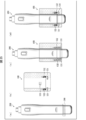
- FIG. 3 is a view showing the operating device shown in FIG. 2 with a front case and a lower cap removed.
- FIG. 3 is a view showing a front case and a front electrode in the controller shown in FIG. 2;
- FIG. 2 it is a figure which shows a back case and a back electrode.
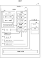
- FIG. 1 It is a block diagram which shows the structure of the X-ray imaging unit shown in FIG.
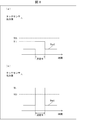
- A is a figure showing the touch sensor output value in the state which the operator has not touched to the 1st touch sensor and the 2nd touch sensor
- (b) is the case where the operator makes the 1st touch sensor and the 2nd touch sensor
- (A) is a figure showing a mode that the 1st touch sensor output value of a 1st touch sensor is smaller than a threshold
- (b) is a figure showing a mode that a 2nd touch sensor output value of a 2nd touch sensor is larger than a threshold
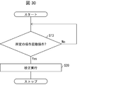
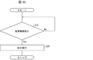
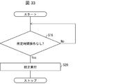
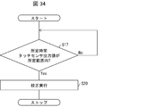
- FIG. 6 is a block diagram showing the configuration of an X-ray imaging unit according to a second embodiment. It is a figure showing the flow of processing of the above-mentioned operating device which performs calibration, when temperature change is more than fixed. It is a figure showing the flow of processing of the above-mentioned operating device which performs calibration, when change of battery voltage is more than fixed. When the frequency
- FIG. 1 is a perspective view showing an operating device for operating an operation target device in the present embodiment together with a holder and the operation target device.
- the operation target apparatus is an X-ray imaging apparatus 2 which irradiates a patient with X-rays, detects X-rays transmitted through the patient, and generates an X-ray image.
- the X-ray imaging apparatus 2 includes an X-ray imaging apparatus main body 1 and a holder 100 (holding mechanism) attached to the X-ray imaging apparatus main body 1. As shown in FIG. 1, the holder 100 detachably holds the operating device 200 (operating device).
- FIG. 2 is a perspective view showing the operating device in the present embodiment.
- the operating device 200 is a remote controller for remotely operating the X-ray imaging apparatus 2.
- the controller device 200 includes a front case 250, a rear case 260, and a lower cap 270, which are housings.
- the controller device 200 has a substantially cylindrical shape, the main switch 210 is provided on the top surface, and the option switch 220 is provided on the top of the circumferential surface.
- the operator holds the peripheral surface of the controller 200, and operates the controller 200 by, for example, pressing the main switch 210 provided on the upper surface with the thumb and the option switch 220 provided on the peripheral surface with the index finger. Do. That is, the X-ray imaging apparatus 2 is operated.
- the main switch 210 is a switch that operates in two steps including a first switch member 201 and a second switch member 202 that have different origin positions when not pressed by the operator.
- the first switch member 201 is configured such that the movement distance to the origin position is longer than that of the second switch member 202.
- Operation unit 280 includes a main switch 210 and an option switch 220 for receiving an operation by the operator.
- the controller 200 outputs an X-ray imaging instruction to the X-ray imaging apparatus 2 when the main switch 210 is pressed, and indicates an X-ray irradiation range of the X-ray imaging apparatus 2 when the option switch 220 is pressed.
- An instruction to turn on or off the lighting of the lighting device is output to the X-ray imaging apparatus 2.
- the main switch 210 includes the first switch member 201 and the second switch member 202 as described above.
- the main switch 210 can press the second switch member 202.
- the controller device 200 performs X-ray imaging (through the holder 100) to the effect that the first switch member 201 is pressed. Output to device body 1. Then, the rotation of the X-ray tube anode target (not shown) in the X-ray imaging apparatus main body 1 starts.
- the X-ray tube anode target requires a certain time to reach a sufficient number of revolutions.
- the controller device 200 Information indicating that the second switch member 202 is pressed is output to the X-ray imaging apparatus main body 1 (via the holder 100).
- the X-ray imaging apparatus main body 1 emits X-rays and performs X-ray imaging.
- the detection of whether or not the operator holds the controller 200 will be described later.
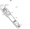
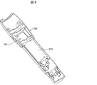
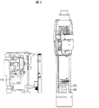
- FIG. 4 to 6 show the internal structure of the controller device 200.
- FIG. FIG. 4 is a view showing a state in which the front case 250 and the lower cap 270 of the operation device 200 are removed
- FIG. 5 is a view showing the front case 250 and the first touch sensor 241
- FIG. It is a figure which shows 260 and the 2nd touch sensor 242. As shown in FIG.
- the operation device 200 includes a touch sensor control unit 234, which is an IC, for example, a first touch sensor 241, A two-touch sensor 242, a communication unit 231 configured of, for example, an IC, and a battery 243 are provided.
- a touch sensor control unit 234 which is an IC, for example, a first touch sensor 241, A two-touch sensor 242, a communication unit 231 configured of, for example, an IC, and a battery 243 are provided.
- the first touch sensor 241 and the second touch sensor 242 are capacitance type electrodes.
- a hole 250a is formed at a position where the option switch 220 is disposed.
- the first touch sensor 241 is disposed below the hole 250 a (in the direction opposite to the direction in which the main switch 210 is provided) and along the inner wall of the front case 250.
- the second touch sensor 242 is disposed along the inner wall of the rear case 260, and is disposed at a position facing the first touch sensor 241 in the radial direction.
- the number of touch sensors is not limited to two, and three or more touch sensors may be arranged side by side along the inner wall of the front case 250 and the rear case 260 in the circumferential direction.
- the touch sensor control unit 234 is electrically connected to the first touch sensor 241 and the second touch sensor 242 (in addition to the other touch sensors if they also have a touch sensor), the first touch sensor 241 and Whether or not the operating device 200 is gripped by the operator based on the change in capacitance of the second touch sensor 242 (including other touch sensors if they also have a touch sensor, and so forth) To detect The detail of the method of the said detection is mentioned later.
- Communication unit 231 transmits an operation signal based on the operation of operation unit 280 to the communication unit of holder 100 by wireless communication. Further, the communication unit 231 may receive an activation signal indicating the activation state of the X-ray imaging apparatus main body 1 from the holder 100.
- the wireless communication method performed by the communication unit 231 is not particularly limited, and examples thereof include Bluetooth (registered trademark) and infrared light.
- FIGS. 4 to 6 show an example in which the touch sensor control unit 234 and the communication unit 231 are configured as separate ICs, but the touch sensor control unit 234 and the communication unit 231 are integrated in one IC. It may be included.
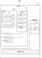
- FIG. 7 is a functional block diagram showing the configuration of the X-ray imaging unit 300 of the present embodiment.
- the X-ray imaging unit 300 includes an X-ray imaging apparatus 2 and an operating device 200.
- the holder 100 has a communication unit 101.
- the communication unit 101 on the X-ray imaging apparatus 2 side may be provided not in the holder 100 but in the X-ray imaging apparatus main body 1.
- the operation device 200 includes a first touch sensor that is an operation unit 280, a control unit 230, a battery 243, a temperature sensor 244, a notification unit 245 (a calibration notification unit, an error notification unit), and at least two touch sensors. And a second touch sensor 242.
- a first touch sensor that is an operation unit 280, a control unit 230, a battery 243, a temperature sensor 244, a notification unit 245 (a calibration notification unit, an error notification unit), and at least two touch sensors.
- the control unit 230 integrally controls the operation of each unit of the operating device 200.
- the control unit 230 includes a communication unit 231, a calibration unit 232, a holding detection unit 233, and a touch sensor control unit 234 (contact determination unit).
- the communication unit 231 is a communication unit on the operation apparatus 200 side, and performs the above-described wireless communication with the communication unit 101 on the X-ray imaging apparatus 2 side.
- the touch sensor control unit 234 controls the driving of the first touch sensor 241 and the second touch sensor 242.
- the touch sensor control unit 234 outputs a drive signal to the first touch sensor 241 and the second touch sensor 242 at predetermined time intervals, and the first touch sensor 241 and the second touch sensor 242 output capacitance values at predetermined time intervals. It outputs to the touch sensor control part 234 as a touch sensor output value.
- the capacitance increases (or decreases).
- FIG. 8 is a diagram showing touch sensor output values in a state where the operator is not in contact with the first touch sensor 241 and the second touch sensor 242, and (b) of FIG. It is a figure showing the touch sensor output value of the state which is contacting the touch sensor 241 and the 2nd touch sensor 242.
- FIG. 8
- the touch sensor control unit 234 determines that the touch sensor output value Vout from the first touch sensor 241 and the second touch sensor 242 during measurement of the presence or absence of the touch is set in advance. If the value V1 is smaller than Vth, the operator determines that the first touch sensor 241 and the second touch sensor 242 do not touch. As shown in (b) of FIG. 8, the touch sensor control unit 234 determines that the touch sensor output value Vout from the first touch sensor 241 and the second touch sensor 242 during measurement of the presence or absence of the touch is set in advance. If the value Vh is equal to or higher than Vth, it is determined that the operator is in contact with the first touch sensor 241 and the second touch sensor 242. The touch sensor control unit 234 determines, for each touch sensor, whether the finger or the like of the operator is in contact or non-contact by comparing the magnitude relationship between the touch sensor output value Vout and the threshold value Vth.
- the touch sensor control unit 234 determines whether or not the operator is gripping the operating device 200 based on the touch sensor output values output from the plurality of touch sensors, and the gripping state is Grip state information indicating whether or not That is, touch sensor control unit 234 determines whether the operation in which at least one of main switch 210 and option switch 220 is pressed is a normal operation intended by the operator or an erroneous operation not intended by the operator. It is also a judgment unit to
- the touch sensor control unit 234 Detect (perform grasp detection).
- the operation device 200 When the operation device 200 has three or more touch sensors, such as four or more, when the capacitance of at least two touch sensors changes so as to be equal to or more than the threshold value Vth, the operation device 200 is gripped. It detects that it is in the gripped state (performs grip detection).
- the touch sensor control unit 234 may monitor whether the touch sensor output value from each touch sensor is constant for a predetermined time or more recorded in advance.
- the operation unit 280 includes the main switch 210 having the first switch member 201 and the second switch member 202, and an option switch 220.
- the operation unit 280 transmits an operation signal corresponding to the operation to the control unit 230.
- the operation signal is a signal for operating the X-ray imaging apparatus 2.
- the control unit 230 When the control unit 230 receives an operation signal from the operation unit 280, and the holding state information generated by the touch sensor control unit 234 indicates a holding state (that is, when holding detection is performed), the communication unit 231 receives the operation signal. Are transmitted to the communication unit 101 on the X-ray imaging apparatus 2 side. Thereby, the X-ray imaging apparatus 2 performs an operation intended by the operator.
- the control unit 230 receives an operation signal from the operation unit 280, if the holding state information acquired by the touch sensor control unit 234 is not the holding state (that is, the holding detection is not performed), the communication unit 231 The operation signal is not transmitted to the communication unit 101 on the X-ray imaging apparatus 2 side.
- the operating device 200 when the operator removes the operating device 200 from the holder 100 and puts it in a pocket of clothes and performs other work other than taking an X-ray image, the operating device 200 is erroneously operated in the pocket.
- the touch sensor control unit 234 detects that the operating device 200 is not in the gripping state. Therefore, even if the operation unit 280 is operated in such a state, the operation signal is not transmitted, and the X-ray imaging apparatus body 1 does not emit X-rays.
- the operation device 200 in a state of being in the pocket may be in contact with the bed or the like while the patient assistance is being performed. Even in such a case, if the conductor does not contact both the area where the first touch sensor 241 is provided and the area where the second touch sensor 242 is provided, the touch sensor control unit 234 Does not detect that the controller device 200 is in the gripping state. Therefore, even if one electrode of the first touch sensor 241 and the second touch sensor 242 contacts the operator through clothes and the other electrode contacts a non-conductive bed or the like, the touch sensor control unit 234 It does not detect that the operating device 200 is in the gripping state.
- the controller device 200 includes at least two electrodes as sensors for detecting a touch of a human body, and when two of the electrodes detect a touch, it detects a gripping state. Therefore, the operation signal is not transmitted to the X-ray imaging apparatus main body 1 even if the operation unit 280 is operated in a state not intended by the operator, that is, in a state in which the operation device 200 is not gripped. As a result, it is possible to prevent X-rays from being emitted from the X-ray imaging apparatus main body 1 due to an erroneous operation which is an operation not intended by the operator.
- the calibration unit 232 illustrated in FIG. 7 calibrates the threshold value Vth for each of a plurality of touch sensors.
- the touch sensor control unit 234 detects the contact and non-contact of the finger of the operator or the like for each touch sensor based on the threshold value Vth calibrated by the calibration unit 232 for each touch sensor. Since each touch sensor is capacitive type, its sensitivity changes depending on the external environment. For this reason, in order to prevent a malfunction, the calibration unit 232 calibrates the threshold value Vth for each touch sensor. In the present embodiment, the calibration unit 232 calibrates the threshold value Vth for each touch sensor when the operation device 200 is mounted on the holder 100.
- the notification unit 245 may be, for example, at least one of a buzzer and a light emitting element (LED).
- the control unit 230 outputs a notification instruction to the notification unit 245 when a predetermined time elapses after the control device 200 is removed from the holder 100. Note that whether the operating device 200 is attached to or removed from the holder 100 is specified by the detection result of the holding and detecting unit 233.
- the notification unit 245 performs a notification operation by at least one of sound and light according to a notification instruction from the control unit 230. That is, the notification unit 245 sounds a buzzer or causes the light emitting element to emit light. Thereby, the notification unit 245 notifies the operator that the operating device 200 has been removed from the holder 100 for a predetermined time.
- the notification unit 245 may perform a notification operation when the calibration unit 232 is performing calibration.
- the calibration unit 232 when the calibration unit 232 starts the execution of calibration, the calibration unit 232 outputs a notification instruction to the notification unit 245.
- the notification unit 245 performs a notification operation by at least one of sound and light. That is, the notification unit 245 sounds a buzzer or causes the light emitting element to emit light.
- the notification unit 245 notifies the operator not to touch the touch sensor with a finger or the like because calibration is being performed.
- the calibration unit 232 may output a notification instruction to the notification unit 245 when the calibration is completed.
- reporting part 245 performs at this time differs from the alerting
- the notification unit 245 may make the buzzer sound different, or make the light emission color of the light emitting element and the light emission mode (for example, whether it is blinking or lighting) different.
- a notification unit (not shown) provided in the holder 100 may perform the notification operation.
- the calibration unit 232 transmits a notification instruction to the holder 100 via the communication unit 231, whereby the notification operation by the notification unit provided in the holder 100 can be realized.
- a notification instruction to the holder 100, it is possible to display a screen according to the leaving instruction on a display unit (not shown) provided in the X-ray imaging apparatus main body 1.
- the holding detection unit 233 detects whether the operating device 200 is attached to the holder 100.
- a state in which the operating device 200 is mounted on the holder 100 is referred to as a “holding state”
- a state in which the operating device 200 is removed from the holder 100 is referred to as a “non-holding state”.
- FIG. 9 is a view showing an internal configuration of the operating device 200 and the holder 100.
- the controller device 200 includes a Hall IC as the holding detection unit 233, and the holder 100 includes the magnet 110.
- the Hall IC senses the magnet 110 of the holder 100 in a state where the operating device 200 is attached to the holder 100.
- the Hall IC detects that the operating device 200 has become the holding state from the non-holding state.
- the Hall IC detects that the controller device 200 has changed from the holding state to the non-holding state.
- the method of detecting the change from the non-holding state to the holding state is not limited to the above example.
- the operating device 200 and the holder 100 are provided with electrodes, and the holding detection unit 233 senses contact of the electrodes with the operating device 200 attached to the holder 100, the operating device 200 is not It may be detected that the holding state is changed to the holding state.
- the operation device 200 is provided with a photo sensor, a micro switch, a heat sensor, and the like, and the holding detection unit 233 obtains a signal output from these, and indicates that the operation device 200 has become a holding state It may be detected.
- the holding detection unit 233 turns on the power of the X-ray imaging apparatus 2 with the operating device 200 attached to the holder 100. It may be considered that the non-holding state is changed to the holding state.
- the calibration unit 232 may perform calibration when the power supply (not shown) of the X-ray imaging apparatus 2 is turned on with the controller 200 mounted on the holder 100.
- the holding detection unit 233 When the holding detection unit 233 detects that the holding state has been entered from the non-holding state, the holding detection unit 233 outputs a signal indicating this (hereinafter referred to as a “holding detection signal”) to the calibration unit 232. Further, when detecting that the non-holding state has been entered from the holding state, the holding detection unit 233 outputs a signal indicating that (hereinafter, referred to as “non-holding detection signal”) to the calibration unit 232.
- a holding detection signal indicating this
- FIG. 10 is a diagram illustrating the flow of the calibration process performed by the operating device 200.
- the holding detection unit 233 monitors whether or not the controller device 200 is mounted on the holder 100 (step S1). Then, when it is detected that the controller device 200 is attached to the holder 100 (Yes in step S1), the calibration unit 232 performs calibration of the threshold value Vth for each of a plurality of touch sensors (step S20).
- the operation device 200 executes calibration when detecting that the device itself is mounted on the holder 100.
- the threshold value Vth of each touch sensor can be calibrated in a situation where the possibility that the operator is holding or operating the operating device 200 is low. Therefore, the calibration of the threshold can be performed at the necessary timing. As a result, power consumption required for calibration can be suppressed. In addition, the possibility of the touch sensor being accurately calibrated can be increased.
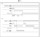
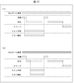
- (Start and stop of calibration) 11 to 13 are time charts of calibration by the operating device 200.
- FIG. the calibration unit 232 can not accurately calibrate when the touch sensor detects a touch. Therefore, it is preferable that the calibration unit 232 start calibration after a predetermined time has elapsed since the controller 200 is mounted on the holder 100. In other words, it is preferable that the calibration unit 232 start the calibration after a predetermined time elapses after acquiring the holding detection signal from the holding detection unit 233. As a result, the operator of the controller device 200 can mount the controller device 200 on the holder 100 and release the hand from the controller device 200 to start calibration.
- the calibration unit 232 may start calibration after waiting for 0.5 seconds after the operation device 200 is attached to the holder 100.
- the time provided for the calibration is not particularly limited, but may be 2.0 seconds as shown in (a) of FIG. 11, and the calibration is continued until the threshold value Vth becomes a value within a predetermined range.
- the predetermined range may be determined based on, for example, the threshold value Vth before correction.
- the controller device 200 goes into the sleep state.
- the calibration unit 232 may be configured not to start calibration or to cancel calibration when it is in a situation where accurate calibration may not be possible. For example, in the case of the example illustrated in (b) of FIG. 11, the calibration unit 232 cancels the calibration when the operating device 200 is removed from the holder 100 during the calibration. Specifically, if the calibration unit 232 acquires a non-holding detection signal from the holding detection unit 233 during the execution of the calibration, the calibration unit 232 cancels the calibration.
- the calibration unit 232 operates the main switch 210 or the option switch 220 before the calibration is performed (that is, during the standby time). If the operation continues, calibration will not start. Specifically, the calibration unit 232 does not start the calibration when the operation signal acquired from the operation unit 280 during the standby time is continuously acquired even when the calibration start timing is reached.
- the calibration unit 232 cancels the calibration when the main switch 210 or the option switch 220 is operated during the calibration. Specifically, if the calibration unit 232 acquires an operation signal from the operation unit 280 during calibration, the calibration unit 232 cancels the calibration.
- the calibration unit 232 does not start the calibration when the touch sensor detects the contact of the human body when the operating device 200 is attached to the holder 100. Specifically, when acquiring the holding detection signal from the holding detection unit 233, the calibration unit 232 does not start the calibration when the touch detection signal is acquired from the touch sensor control unit 234.
- the calibration unit 232 may cancel the calibration when the touch sensor detects the touch of the human body during the execution of the calibration.
- the calibration unit 232 when the calibration unit 232 is in a situation where there is a possibility that accurate calibration can not be performed, the operator is kept in contact with the touch sensor by not starting calibration or by canceling calibration. Calibration can be performed to prevent an inappropriate threshold being set.
- the calibration unit 232 notify the notification unit 245 that the calibration has not been started or that the calibration has been canceled. . In other words, it is preferable that the calibration unit 232 notify the notification unit 245 when an error occurs in the calibration. Specifically, the calibration unit 232 causes the notification unit 245 to perform a notification operation by outputting a notification instruction to the notification unit 245. This allows the operator to recognize that an error has occurred in calibration.
- the notification operation is preferably different from the notification operations during and after calibration and the notification operation when the controller device 200 is removed from the holder 100 for a predetermined time.
- the notification unit 245 continues the notification operation until the operating device 200 is mounted again on the holder 100 until the error is eliminated.
- the time of the notification operation of the notification unit 245 is not limited to this example.
- the calibration unit 232 stands by until a retry operation is performed.
- the retry operation is, for example, mounting the operating device 200 on the holder 100 again.
- the calibration unit 232 executes calibration again.
- the controller device 200 is removed from the holder 100 and mounted on the holder 100 again, the calibration unit 232 executes calibration again.
- the calibration unit 232 exceptionally resumes the calibration without performing the above-described retry operation. This is because when the operation of the main switch 210 or the option switch 220 is performed with the holder 100 attached, predetermined processing is performed (in other words, the operation is not strictly an error). It is. In the case of this example, when the operation of the main switch 210 or the option switch 220 is finished as shown in FIG. 12, that is, when the operation signal from the operation unit 280 is not obtained, the calibration unit 232 starts calibration. .
- the calibration may be performed again without waiting for the retry operation.
- a retry operation may be on standby.
- the calibration basically ends in about one second. Therefore, in the example of FIG. 12, it is provided for calibration when the operation of the main switch 210 or the option switch 220 is finished, or when the touch sensor does not detect the touch of the human body in the example of FIG.
- the calibration unit 232 may perform calibration if the elapsed time remains for more than one second.
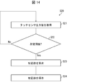
- FIG. 14 is a diagram illustrating the flow of the calibration process performed by the calibration unit 232.
- step S21 the calibration unit 232 next acquires a touch sensor output value for each touch sensor (step S21).
- a calibration value that is, a new threshold value is generated for each touch sensor from a plurality of touch sensor output values for the predetermined number of times.
- calculate step S23. For example, the calibration unit 232 obtains a touch sensor output value for each touch sensor 32 times, and calculates an average value of 32 touch sensor output values for each touch sensor. Then, a calibration value, that is, a new threshold value is calculated for each of the plurality of touch sensors from the average value.
- the calibration unit 232 stores the calculated calibration value, that is, the new threshold value in the touch sensor control unit 234 (step S24). Thereby, the calibration by the calibration unit 232 is completed.
- the step of acquiring the touch sensor output value for the predetermined number of times may be referred to as a touch sensor output value acquisition step.
- the step of calculating the calibration value may be referred to as a calibration value calculation step.
- the calibration unit 232 calibrates the threshold value by executing a calibration process including a touch sensor output value acquisition step and a calibration value calculation step.
- the calibration unit 232 calculates a calibration value of a certain touch sensor using a plurality of touch sensor output values acquired in time series from the touch sensor. For example, in the case of the first touch sensor 241, the calibration unit 232 obtains 32 touch sensor output values in time series by the predetermined number of times (for example, 32 times) from the first touch sensor 241 in the touch sensor output value acquisition step. get. Next, the calibration unit 232 calculates the average value of the touch sensor output values from the 32 touch sensor output values acquired in the touch sensor output value acquisition step in the calibration value calculation step, and the first touch sensor from the average value. Calculate the calibration value of 241. Thereafter, the calibration unit 232 calibrates the threshold of the first touch sensor 241 using the calibration value (compensates the threshold to the calculated calibration value). The other touch sensors are also calibrated for each touch sensor.
- the touch sensor output value is largely different by touching the touch sensor with the finger or the like while the calibration unit 232 is performing calibration, the accurate calibration value can not be calculated.
- a process of determining whether to perform calibration using the calibration value calculated by the calibration unit 232 this time or discard the calibration value calculated this time (do not change the threshold) may be provided. preferable.
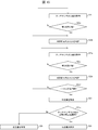
- FIG. 15 is a diagram showing a flow of processing for determining the presence or absence of a touch on the touch sensor during the touch sensor output value acquisition step of the calibration unit 232. As shown in FIG. 15, in order to calculate an accurate calibration value, the presence or absence of a touch on the touch sensor may be determined during calibration of the touch sensor by the calibration unit 232.
- steps S22a to S22f are provided in place of step S22 shown in FIG. 14, and steps S23a and S25 are further provided.
- the calibration unit 232 will be described as performing the process shown in FIG. 15 after step S1 is executed. However, when the process of the calibration unit 232 shown in FIG. 15 is performed, the process of step S1 described above is performed. May be omitted. The same applies to the processing described with reference to FIGS. 16 to 23 below.
- step S1 when the above-described step S1 is Yes (or when execution of calibration is started when predetermined timing comes, etc.), the calibration unit 232 then outputs the touch sensor for each touch sensor. A value is acquired (step S21).
- the calibration unit 232 acquires a touch sensor output value for each touch sensor (first step: for example 16 times) which is a part of the total number of times (for example, 32 times) (Yes in step S22a), The calibration unit 232 determines whether the difference (the difference between the maximum value and the initial value) of the touch sensor output values for the first predetermined number of times is within a predetermined range determined in advance, and stores the determination result. (Step S22b). Next, the calibration unit 232 determines whether or not the fluctuation of the touch sensor output value acquired in step S22b is within a predetermined range set in advance, and stores the determination result (step S22b).
- the calibration unit 232 acquires a touch sensor output value for each touch sensor (step S22 c).
- the calibration unit 232 acquires the touch sensor output value for each touch sensor (the second predetermined number of times (for example, 16 times), which is a part of the total predetermined number of times (for example, 32 times) (Yes in step S22d).
- the calibration unit 232 determines whether the difference (the difference between the maximum value and the minimum value) of the touch sensor output values for the second predetermined number of times is within a predetermined range set in advance, and stores the determination result. (Step S22e).
- the calibration unit 232 determines whether or not the touch sensor output value of each touch sensor has been acquired for the total predetermined number of times (for example, 32 times) necessary to calculate the calibration value (step S22 f). If No in step S22f, the process returns to step S22b.
- step S22f when it is determined that the calibration unit 232 acquires the touch sensor output value of each touch sensor for the total predetermined number of times (for example, 32 times) necessary for calculation of the calibration value (Yes in step S22f), A calibration value is calculated for each touch sensor from the touch sensor output value of each touch sensor for a predetermined total number of times (for example, 32 times) acquired in steps S21, S22a, S22c, S22d, and S22f (step S23).
- the calibration unit 232 refers to the determination result determined in steps S22b and S22e during acquisition of touch sensor output values for the total predetermined number of times, and the touch sensor output value difference for each touch sensor ( It is determined whether or not the difference between the maximum value and the minimum value is within a predetermined range (step S23a: touch sensor output value determination step).
- step S23a when the calibration unit 232 determines that the difference between the touch sensor output values is within the predetermined range (Yes in step S23a), the calibration value calculated in step S23 is stored in the touch sensor control unit 234 ( Step S24). That is, the calibration unit 232 completes the calibration by correcting the threshold value to the newly calculated calibration value. This is because, in the case of Yes in step S23a, it can be determined that there has been no touch of the operator's finger or the like on the touch sensor until the touch sensor output value for a total predetermined number of times (for example, 32 times) has been acquired. is there. Then, using the calibration value calculated in step 23, the touch sensor control unit 234 performs gripping detection.
- step S23a when the calibration unit 232 determines in step S23a that the fluctuation of the touch sensor output value is out of the predetermined range (No in step S23a), the calibration value calculated in step S23 is discarded and the calibration value is Are not stored in the touch sensor control unit 234 (step S25). That is, the calibration unit 232 stops calibration without correcting the threshold and maintains the calibration value at the time of the previous calibration. This is because, in the case of No in step S23a, it can be determined that there has been no touch of the operator's finger or the like on the touch sensor until the touch sensor output value for a total predetermined number of times (for example 32 times) has been acquired. It is because it is not possible to calculate the correct calibration value. As a result, the touch sensor control unit 234 performs the grip detection using the previously calculated calibration value already stored in itself, not the calibration value calculated in step S23.
- the calibration unit 232 collectively determines in step S23a whether steps S22b and S22e are omitted and the fluctuation of the touch sensor output value acquired in step S22b one or more times falls within a predetermined range. May be Also, the calibration values not used in step S25 may be stored without being deleted.
- the calibration unit 232 determines whether the difference between the touch sensor output values acquired in the touch sensor output value acquiring step (steps S21, S22a, S22c, and S22d) is within the predetermined range. For example, the calibration value calculated in the calibration value calculation step (step S23) after this is stored in the touch sensor control unit 234 (Yes in step S23a; S24). That is, the calibration unit 232 completes the calibration by changing the threshold value to the calibration value calculated in the calibration value calculation step.
- the calibration unit 232 further calculates the calibration value (step The calibration value calculated in S23) is discarded (No. S25 in step S23a). That is, the calibration unit 232 cancels the calibration by maintaining the threshold stored in the touch sensor control unit 234, which is the calibration value at the time of the previous calibration.
- the number of recalibrations when the operating device 200 does not operate properly can be reduced, and the battery life can be extended.
- the touch sensor control unit 234 detects a subtle change in the touch sensor output value, thereby accurately determining whether a finger or the like is touching the touch sensor. A decision can be made.
- FIG. 16 is a diagram showing a flow of processing for determining the presence or absence of a touch on the touch sensor after the touch sensor output value acquiring step of the calibration unit 232.
- the calibration unit 232 may collectively determine the touch on the touch sensor not in the touch sensor output value acquisition step but after the touch sensor output value acquisition step.
- step S1 when the above-described step S1 is Yes (or when execution of calibration is started when predetermined timing comes, etc.), the calibration unit 232 then outputs the touch sensor for each touch sensor. A value is acquired (step S21).
- step S22 When the calibration unit 232 acquires the touch sensor output value for each touch sensor a predetermined number of times (for example, 32 times) (Yes in step S22), next, the calibration unit 232 compares the touch sensor output values for the predetermined number of times ( It is determined for each touch sensor whether the difference between the maximum value and the minimum value is within a predetermined range (step S23a).
- step S23a if the calibration unit 232 determines that the difference between the touch sensor output values is within the predetermined range for each touch sensor (Yes in step S23a), the touch sensor touch for a predetermined number of times (for example, 32 times) From the sensor output value, a calibration value is calculated for each touch sensor (step S23).
- step S23a when the calibration unit 232 determines in step S23a that the difference between the touch sensor output values is outside the predetermined range (No in step S23a), calibration of the touch sensor is not performed without calculating the calibration value of the touch sensor. Cancel
- the calibration unit 232 determines whether the difference between the plurality of touch sensor output values acquired in the touch sensor output value acquisition step (steps S21 and S22) is within the predetermined range or outside the predetermined range.
- the touch sensor output value determination step (step S23a) is performed before the calibration value calculation step (step S23).
- the calibration unit 232 determines that the difference between the plurality of touch sensor output values acquired in the touch sensor output value acquisition step (steps S21 and S22) is within a predetermined range.
- the threshold value is changed to the calibration value calculated in the calibration value calculation step (step S23).
- the calibration unit 232 determines that the difference between the plurality of touch sensor output values acquired in the touch sensor output value acquisition step (steps S21 and S22) is outside the predetermined range. If determined, the calibration value calculation step (step S23) is not performed. That is, in this case, the calibration unit 232 cancels the calibration of the touch sensor without calculating the calibration value of the touch sensor.
- the number of recalibrations when the operating device 200 does not operate properly can be reduced, and the battery life can be extended.
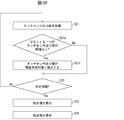
- FIG. 17 is a diagram showing a flow of processing for canceling the calibration when there is a touch on the touch sensor during the touch sensor output value acquisition step of the calibration unit 232.
- the calibration unit 232 may end the execution of calibration when it is determined that there is a touch on the touch sensor during calibration, as shown in FIG.
- the calibration unit 232 when at least one of the above-described steps S11 to S17 is Yes (or when execution of calibration starts when predetermined timing or the like comes), the calibration unit 232 then performs a touch sensor, for example.
- the touch sensor output value is acquired each time (step S21).
- the calibration unit 232 acquires a touch sensor output value for each touch sensor (first step: for example 16 times) which is a part of the total number of times (for example, 32 times) (Yes in step S22a).
- the calibration unit 232 determines whether the difference between the touch sensor output values for the first predetermined number of times (the difference between the maximum value and the minimum value) is within a predetermined range set in advance (Step S22 ba).
- step S22ba if the calibration unit 232 determines that the difference (the difference between the maximum value and the minimum value) of the touch sensor output values for the first predetermined number of times is outside the predetermined range set in advance (No in step S22ba) The calibration of the touch sensor is stopped without calculating the calibration value of the touch sensor.
- Step S22ba determines that the difference between the touch sensor output values (the difference between the maximum value and the minimum value) for the first predetermined number of times is within the predetermined range set in advance (Step S22ba) Yes).
- the processes of step S22c and step S22d are sequentially performed.
- step S22d if the calibration unit 232 acquires a touch sensor output value for each touch sensor for a second predetermined number of times (for example, 16 times) which is a part of the total predetermined number of times (for example, 32 times) (Yes in step S22d) Next, the calibration unit 232 determines whether or not the difference (the difference between the maximum value and the minimum value) of the touch sensor output values for the second predetermined number of times is within a predetermined range set in advance (step S22ea).
- step S22d when the calibration unit 232 determines that the difference between the touch sensor output values for the second predetermined number (the difference between the maximum value and the minimum value) is outside the predetermined range set in advance, The calibration of the touch sensor is stopped without calculating the calibration value of the touch sensor.
- step S22d the calibration unit 232 determines that the difference (the difference between the maximum value and the minimum value) of the touch sensor output values for the second predetermined number of times is within the predetermined range set in advance. Then, the processes of steps S22f, S23, and S24 are sequentially performed.
- the number of recalibrations when the operating device 200 does not operate properly can be reduced, and the battery life can be extended.
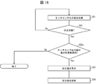
- FIG. 18 is a diagram showing the flow of processing of the configuration including the determination of the suitability of the calibration value calculated by the calibration unit 232.
- step S1 when the above-described step S1 is Yes (or when execution of calibration is started when predetermined timing comes, etc.), the calibration unit 232 then outputs the touch sensor for each touch sensor. A value is acquired (step S21). Then, the calibration unit 232 performs the process of steps S22 and S23 described with reference to FIG.
- step S23 the calibration unit 232 calculates a calibration value for each touch sensor from a plurality of touch sensor output values for a predetermined number of times.
- the calibration unit 232 determines whether the difference between the calibration value calculated in step S23 and the calibration value (the calibration value stored in the touch sensor control unit 234) calculated last time and currently used is within a predetermined range. It is determined whether or not it is (step S23b).
- step S23b the calibration unit 232 determines that the difference between the calibration value calculated in step S23 and the calibration value (the threshold stored in the touch sensor control unit 234) when previously calibrated is within the predetermined range. (Yes in step S23b), the calibration value calculated in step S23 is assumed to be normal, and the calibration value is stored in the touch sensor control unit 234 (step S24). That is, the calibration unit 232 changes the threshold value to the calibration value calculated in step S23, and completes the calibration.
- step S23b if the calibration unit 232 determines that the difference between the calibration value calculated in step S23 and the calibration value (the threshold stored in the touch sensor control unit 234) when previously calibrated is outside the predetermined range (No in step S23b), it is presumed that there is a touch of a finger or the like on the touch sensor during calibration, the calibration value calculated in step S23 is discarded, and the touch sensor control unit 234 is not stored (step S25). Thereby, the calibration unit 232 cancels the calibration of the touch sensor.
- the difference between the calibration value calculated in the calibration value calculation step (step 23) and the threshold which is the calibration value when previously calibrated is within the predetermined range If it is inside, the threshold value is changed to the calibration value calculated in the calibration value calculation step (step 23) (step S24).
- the calibration unit 232 can estimate that there is a touch with a touch sensor or the like during calibration. Therefore, the calibration value calculated in the calibration value calculation step (step 23) is discarded, and the threshold is not changed (step S25). That is, the calibration unit 232 cancels the calibration by maintaining the threshold stored in the touch sensor control unit 234, which is the calibration value at the time of the previous calibration.
- the calibration values not used in step S25 may be stored without being deleted.
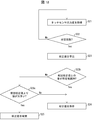
- FIG. 19 is a diagram showing a process flow of a modification example of calibration including determination of whether the calibration value calculated by the calibration unit 232 is appropriate. As shown in FIG. 19, the calibration unit 232 may further determine the magnitude relationship between the calculated calibration value and the currently used threshold value, and may adopt one in which the value is considered to be correct.
- step S23b if the calibration value calculated in the calibration value calculation step (step S23) is out of the predetermined range (No in step S23b), the calibration unit 232 further determines whether the calibration value is smaller than the threshold value. It is determined (step S23c).
- step S23c when the calibration unit 232 determines that the calibration value calculated in step S23 is smaller than the threshold that was previously calibrated and stored in the touch sensor control unit 234 (No in step S23c), the previously calibrated threshold Then, the calibration value calculated in step S23 is estimated to be more accurate, and the calibration value calculated in step S23 is stored in the touch sensor control unit 234 (step S24). Thus, the calibration unit 232 completes the execution of the calibration.
- step S23c determines that the calibration value calculated in step S23 is equal to or larger than the threshold value that was previously calibrated and stored in the touch sensor control unit 234 (Yes in step S23c).
- the calibrated threshold value is estimated to be more accurate than the calibration value calculated in step S23, and the calibration value calculated in step S23 is discarded and not stored in the touch sensor control unit 234 (step S25). Thereby, the calibration unit 232 cancels the calibration.
- the calibration values not used in step S25 may be stored without being deleted.
- the calibration unit 232 may correct a plurality of touch sensor output values acquired simultaneously during calibration.
- FIG. 20 is a diagram illustrating a flow of the calibration unit 232 correcting at least one value of a plurality of touch sensor output values while calibration is being performed.
- the calibration unit 232 may perform the calibration process shown in FIG. 20 instead of the calibration process shown in FIG.
- step S1 when, for example, the above-described step S1 is Yes (or when execution of calibration is started due to, for example, a predetermined timing), the calibration unit 232 then performs touch sensors for each touch sensor. An output value is acquired (step S21).
- the calibration unit 232 determines whether at least one touch sensor output value among the touch sensor output values from the touch sensors simultaneously acquired in step S21 is equal to or greater than a threshold (step S21 a).
- step S21a when the calibration unit 232 determines that at least one touch sensor output value is greater than or equal to the threshold (Yes in step S21a), the touch sensor output value of the touch sensor determined to be greater than or equal to the threshold is Based on the value of the touch sensor output value less than the threshold value, the correction value is corrected to a value less than the threshold value (step S21 b). Thereafter, the processes of steps S22 to S24 shown in FIG. 14 are sequentially performed.
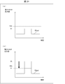
- FIG. 21 is a diagram illustrating how the calibration unit 232 corrects at least one value of the plurality of touch sensor output values during calibration.
- the calibration unit 232 may correct the touch sensor output value as illustrated in FIG. (A) of FIG. 21 shows that the first touch sensor output value V1out of the first touch sensor 241 is smaller than the threshold, and (b) shows that the second touch sensor output value V2out of the second touch sensor 242 is higher than the threshold It is a figure showing a big appearance.
- the operating device 200 includes, for example, two touch sensors of a first touch sensor 241 and a second touch sensor 242 shown in FIG. 7.
- the touch sensor output value obtained by the calibration unit 232 from the first touch sensor 241 at a certain time during calibration is the first touch sensor output value V1out shown in (a) of FIG.
- the touch sensor output value obtained by the calibration unit 232 from the second touch sensor 242 is the second touch sensor output value V2out illustrated in (b) of FIG.
- step S21a shown in FIG. 20 the calibration unit 232 refers to the threshold value Vth stored in the touch sensor control unit 234, and determines whether the touch sensor output value is equal to or greater than the threshold value Vth for each touch sensor. judge.
- the first touch sensor output value V1out is a value Vl that is less than the threshold value Vth
- the second touch sensor output value V2out is a value Vh which is equal to or greater than the threshold value Vth.
- the operator does not grip (hold) the operation unit 280, It is presumed that a finger or the like has accidentally touched one of the two touch sensors.
- step S21b instead of starting the calibration from the beginning, in step S21b, the value Vh of the second touch sensor output value V2out is corrected to the value Vl of the first touch sensor output value V1out. Then, as shown in steps S22 to S24, the calibration unit 232 continues the execution of the calibration and ends the calibration. This makes it possible to prevent recalibration due to a finger or the like touching during calibration, and to delay the battery life.
- the touch sensor output value of one touch sensor is equal to or more than the threshold, and the touch sensor output of another touch sensor
- the touch sensor output value which is equal to or more than the threshold value may be corrected to be an average value of other touch sensor output values which are less than the threshold value.
- FIG. 22 is a diagram illustrating a flow of stopping the calibration according to the values of the plurality of touch sensor output values while the calibration unit 232 is performing calibration.
- the calibration unit 232 may perform the calibration process shown in FIG. 22 instead of the calibration process shown in FIG. In the case where the process shown in FIG. 22 is performed, the calibration unit 232 performs calibration when the touch sensor detects a touch of a human body when the operating device 200 is mounted on the holder 100 as described with reference to FIG. You may omit the structure which does not start.
- step S1 when, for example, the above-described step S1 is Yes (or when execution of a lattice pattern is started due to, for example, a predetermined timing), the calibration unit 232 The touch sensor output value is acquired for each touch sensor (step S21).
- the calibration unit 232 determines that at least one touch sensor output value among the touch sensor output values from the touch sensors simultaneously acquired in step S21 is equal to or greater than the threshold stored in the touch sensor control unit 234. It is determined whether or not (step S21a).
- step S21a when the calibration unit 232 determines that at least one touch sensor output value is equal to or more than the threshold stored in the touch sensor control unit 234 (Yes in step S21a), the touch sensor output value is output a predetermined number of times. Without acquiring, the calibration is canceled (step S26). After that, the calibration unit 232 may cause the notification unit 245 to perform a notification operation in order to notify that the calibration has not ended normally.
- step S21a when the calibration unit 232 determines that at least one touch sensor output value is less than the threshold stored in the touch sensor control unit 234 (No in step S21a), the process proceeds to step S22 illustrated in FIG. The process proceeds to steps S23 and S24 in order, and the calibration ends normally.
- the calibration unit 232 estimates that a finger or the like has touched any one of the plurality of touch sensors when any of the plurality of touch sensor output values becomes equal to or greater than the threshold, and thereafter Acquisition of the touch sensor output value, that is, the execution of the calibration is discontinued. This can delay the battery life.
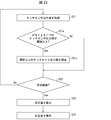
- the calibration unit 232 may discard some touch sensor output values according to the values of the plurality of touch sensor output values acquired simultaneously during the calibration.
- FIG. 23 is a diagram illustrating a flow of discarding some touch sensor output values according to the values of the plurality of touch sensor output values while the calibration unit 232 is performing calibration.
- the calibration unit 232 may perform the calibration process shown in FIG. 23 instead of the calibration process shown in FIG.
- step S1 when, for example, the above-described step S1 is Yes (or when execution of a lattice pattern is started due to, for example, predetermined timing being reached), the calibration unit 232 The touch sensor output value is acquired for each touch sensor (step S21).
- the calibration unit 232 determines that at least one touch sensor output value among the touch sensor output values from the touch sensors simultaneously acquired in step S21 is equal to or greater than the threshold stored in the touch sensor control unit 234. It is determined whether or not (step S21a).
- step S21a when the calibration unit 232 determines that at least one touch sensor output value is greater than or equal to the threshold stored in the touch sensor control unit 234 (Yes in step S21a), the touch sensor output value greater than or equal to the threshold Are discarded (step S21 c).
- step S21a when the calibration unit 232 determines that at least one touch sensor output value is not greater than or equal to the threshold stored in the touch sensor control unit 234 (No in step S21a), the process of steps S22, S23, and S24 is performed. And complete the calibration run.
- the touch sensor output value of the touch sensor whose touch sensor output value is discarded is data for a predetermined number of times (for example, 32 times). Without, the number of touch sensor output values is smaller by the amount discarded. For example, when one touch sensor output value is discarded, the calibration unit 232 determines the calibration value from the touch sensor output value for the touch sensor by subtracting the number of times discarded from the predetermined number of times. Calculate (step S23).
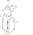
- FIG. 24 is a perspective view showing the appearance of the operating device 200 and the holder 100 according to the present modification.
- the holder 100 may be provided with wall portions 120 (contact preventing portions) on the front and back as shown in FIG.
- the wall portion 120 prevents contact of the human body with the touch sensor in the holding state.
- the upper end of the wall portion 120 is above the position where the touch sensor is provided in the operation device 200.
- the operator can not attach the operating device 200 to the holder 100 while touching the touch sensor. Therefore, when the operating device 200 is attached to the holder 100, it is possible to prevent the situation where the calibration is not performed because the touch sensor detects the contact of the human body.
- the wall portion 120 illustrated in FIG. 24 is an example, and the configuration for preventing the contact of the human body with the touch sensor in the holding state is not limited to this example.
- the upper end of the wall 120 may reach near the upper end of the operating device 200.
- FIG. 25 is a diagram showing an example of the configuration of the controller 200 and the holder 100 according to the present modification.
- FIG. 26 is a diagram showing another example of the calibration of the holder 100 according to the present modification.
- the holder 100 may include a mechanism (hereinafter, referred to as a lifting mechanism) for lifting the controller 200 when the calibration is completed. Thus, the operator can be notified that the calibration has been completed.
- a lifting mechanism for lifting the controller 200 when the calibration is completed.
- the holder 100 includes a protrusion 131 and a spring 132.
- the spring 132 has one end fixed to the holder 100 and the other end connected to the protrusion 131.
- the operating device 200 has the level
- FIG. As shown in (c) of FIG. 25, when the operating device 200 is attached to the holder 100, the protrusion 131 is caught on the step 290, and the protrusion 131 is pushed to the bottom of the holder 100. extend.
- the spring 132 may be configured to maximize the reaction force when the protrusion 131 reaches the bottom of the holder 100.
- the holder 100 shown in FIG. 25 is provided with a lock mechanism (removal blocker) that blocks the removal of the controller device 200 while the calibration unit 232 is performing calibration.
- the lock mechanism includes, for example, a solenoid, a movable plate, and a coil spring (not shown).
- the solenoid, the movable plate, and the coil spring are provided on the back side of the holder 100.
- the movable plate is rotatably supported at both ends of a U-shape (shaft support portion), and one bent portion of the shaft support portion is connected to the solenoid via a plunger.
- a hook (not shown) projecting toward the front side of the holder 100 is formed at the end opposite to the pivotally supporting portion.
- the hook has an inclined surface on the insertion direction side of the operating device 200.
- the holder 100 is formed with a hole 133 in which the hook can be moved in and out according to the movement of the movable plate.
- the hole 133 is opposed to the engagement hole (not shown) of the operating device 200 when the operating device 200 is mounted.
- a coil spring is provided between the cover 140 and the movable plate, and biases the movable plate to the front side of the holder 100.
- the solenoid causes the movable plate to rotate in the direction opposite to the biasing force by attracting the plunger by the magnetic force when energized.
- the movable plate can be locked by the hook projecting from the hole 133 with the movement of the solenoid at the time of non-energization and engaging with the engagement hole of the controller 200.
- the movable plate can be unlocked by the hook being inserted into the hole 133 along with the movement of the solenoid at the time of energization, and the engagement with the engagement hole of the operating device 200 being released.
- the calibration unit 232 controls energization of the solenoid. Specifically, when calibration is started, the calibration unit 232 causes the solenoid to start energization. Thus, the holder 100 can be locked so that the operating device 200 can not be removed only while calibration is being performed. Thus, the operator can be prevented from touching the touch sensor during calibration.
- the calibration unit 232 stops energization of the solenoid. Thereby, the lock of the operating device 200 is released, and the operating device 200 is lifted by the reaction force of the spring 132 (see (d) in FIG. 25).
- the lifting mechanism which concerns on this modification is not limited to the example of FIG.
- the lifting mechanism may be as shown in FIG.
- the holder 100 may be provided with an L-shaped hook 134 and a solenoid 135.
- the calibration unit 232 does not energize the solenoid 135 when the operating device 200 is not attached to the holder 100 and when the operating device 200 is calibrated. Therefore, as shown in FIG. 26A, the L-shaped hook 134 is not attracted to the solenoid 135. When the operation device 200 is inserted (mounted) into the holder 100 in this state, the step portion 290 is hooked on the L-shaped hook 134.
- the calibration unit 232 causes the solenoid 135 to be energized.
- the L-shaped hook 134 is attracted to the solenoid 135, and the L-shaped hook 134 is inclined. Thereby, the controller 200 is pushed up.
- the calibration unit 232 stops the energization of the solenoid 135 when a predetermined time has elapsed since the start of the energization, or when the sensor (not shown) detects that the operating device 200 is removed from the holder 100. . As a result, the L-shaped hook 134 returns to the state where it is not attracted by the solenoid 135.
- the lifting mechanism is suitable for the holder 100 in which the upper end of the wall portion 120 described in the first modification is near the upper end of the operating device 200.
- the operator can easily remove the operating device 200 by lifting the operating device 200 by the lifting mechanism.
- a sensor may be provided in the holder 100, and it may be determined based on the detection result of the sensor whether the operator is touching the operating device 200 mounted in the holder 100.
- the holder 100 includes a touch sensor, a photo sensor, and the like. These sensors may be provided at positions where it can be detected that the operator is touching the operating device 200 mounted on the holder 100. Further, detection results of these sensors are transmitted to the control unit 230 of the controller device 200 via the communication unit 101.
- the calibration unit 232 determines whether the operator is touching the operation device 200 based on the detection result from the sensor provided in the holder 100. For example, when the sensor provided in the holder 100 is a touch sensor, the calibration unit 232 receives a touch sensor output value. Then, the calibration unit 232 determines that the touch sensor output value is a value equal to or greater than a predetermined threshold (not illustrated) (in other words, if the value indicates that the operator shakes the touch sensor), It is determined that the operator is touching the operating device 200. If the calibration unit 232 determines that the operator is touching the operation device 200, the calibration unit 232 does not start calibration, and performs notification by the notification unit 245 (see FIG. 13).
- a predetermined threshold not illustrated
- the conditions for performing the calibration are not limited to the case where it is detected that the controller device 200 is mounted on the holder 100 described in the first embodiment.
- an operating device 200 will be described which performs calibration when a condition different from that of the first embodiment is satisfied.
- FIG. 27 is a functional block diagram showing the configuration of the X-ray imaging unit 300 of the present embodiment.
- the operating device 200 shown in FIG. 27 is different from the operating device 200 shown in FIG. 7 in that the battery 243 and the temperature sensor 244 are newly added, and the control unit 230 is newly added to the battery control unit 235 and temperature.
- the sensor controller 236 and the counter 237 are included.
- the battery control unit 235 monitors the remaining amount of the battery 243 by monitoring the voltage of the battery 243 (hereinafter, may be referred to as a battery voltage).
- the battery 243 is a power supply that supplies power to each unit of the operation device 200 such as the control unit 230, the temperature sensor 244, the notification unit 245, the first touch sensor 241, and the second touch sensor 242.
- the temperature sensor control unit 236 controls the driving of the temperature sensor 244.
- the temperature sensor 244 measures the temperature, and outputs the measured temperature sensor value to the temperature sensor control unit 236.
- the temperature sensor 244 may be provided inside the front case 250 and the rear case 260, or may be attached to any of the front case 250 and the rear case 260.
- the counter 237 counts at least one of the count of the number of operations of the operation unit 280 and the elapsed time after the operation unit 280 is operated.
- the calibration unit 232 preferably performs calibration when at least one of predetermined conditions shown in the following (1) to (7) is satisfied. That is, it is preferable that the calibration unit 232 start the execution of the calibration when at least one of the processes in the following steps S11 to S17 is Yes.
- the predetermined condition under which the calibration unit 232 starts the execution of the calibration is a predetermined condition in the process performed when any of the units of the controller device 200 receives the supply of the voltage from the battery as the power supply. .
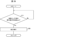
- FIG. 28 is a diagram showing the flow of processing of the controller device 200 performing calibration when the temperature change is a certain level or more.
- a predetermined range of the amount of change of the temperature sensor value that allows fluctuation is set in advance in the temperature sensor control unit 236 based on the temperature sensor value at the time of previous calibration. That is, the upper limit value and the lower limit value of the allowable temperature sensor value are set as predetermined values based on the temperature sensor value at the time of the previous calibration.
- the temperature sensor control unit 236 monitors whether or not the change amount of the temperature sensor value acquired from the temperature sensor 244 is equal to or more than a predetermined range set in advance (step S11).
- the calibration unit 232 executes calibration. It is determined that the predetermined condition is satisfied, and calibration of the threshold value Vth is performed for each of the plurality of touch sensors (step S20).
- the touch sensor output value which the touch sensor control part 234 acquires from each touch sensor may have a temperature characteristic. Therefore, even if the temperature sensor value changes when the temperature changes, the temperature sensor value does not cause a malfunction (error in detection of contact and non-contact of the operator's finger or the like with each touch sensor).
- a predetermined value of the amount of change from the time of correction before is stored in the temperature sensor control unit 236.
- the calibration unit 232 determines that the predetermined condition for performing calibration is satisfied, Perform calibration. Thereby, even if there is a temperature change, the calibration unit 232 can calibrate the threshold value Vth of each touch sensor before causing a malfunction. In addition, after calibrating the threshold value, the calibration unit 232 resets (changes) the range of the temperature sensor value that is allowed based on the temperature sensor value at the time of calibration.
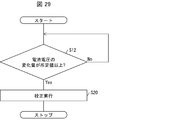
- FIG. 29 is a diagram showing the flow of processing of the controller device 200 that performs calibration when the change in battery voltage is equal to or higher than a certain level.
- the range of the change amount of the battery voltage in which the fluctuation is permitted is set in advance in the battery control unit 235 based on the battery voltage at the time of the previous calibration. That is, the upper limit value and the lower limit value of the allowable battery voltage are set as predetermined values based on the battery voltage at the time of the previous calibration.
- the battery control unit 235 monitors whether or not the change amount of the battery voltage of the battery 243 is equal to or more than a predetermined range set in advance (step S12).
- the calibration unit 232 determines that the change amount of the battery voltage of the battery 243 is equal to or more than a predetermined range set in advance (Yes in step S12), the calibration unit 232 satisfies a predetermined condition for performing calibration. It is determined that the threshold value Vth is calibrated for each of a plurality of touch sensors (step S20).
- the touch sensor output value obtained by the touch sensor control unit 234 from each touch sensor may change when the battery voltage changes. And since the battery 243 supplies electric power to each part, use of the operating device 200 degrades (decreases) the battery voltage. Therefore, the battery control unit 235 stores a predetermined range in which the fluctuation of the battery voltage is permitted without causing a malfunction even when the battery voltage is lowered.
- the calibration unit 232 determines that the predetermined condition for performing the calibration is satisfied, and executes the calibration. Thus, even if there is a change in battery voltage, the calibration unit 232 can calibrate the threshold value Vth of each touch sensor before causing a malfunction. Further, after calibrating the threshold value, the calibration unit 232 resets (changes) the range of the acceptable battery voltage based on the battery voltage at the time of calibration.
- FIG. 30 is a diagram showing a flow of processing of the operation device 200 that performs calibration when the number of operations of the operation unit 280 is equal to or more than a certain value.
- the counter 237 counts the number of times the operation unit 280 has been operated (operation number). Further, it is assumed that the predetermined number of operations of the operation unit 280 is set in the counter 237 in advance.
- the counter 237 monitors whether the number of operations of the operation unit 280, for example, the number of times the main switch 210 or the option switch 220 is pressed, is equal to or more than a predetermined number of operations set in advance. (Step S13).
- step S13 if the counter 237 determines that the number of operations of the operation unit 280, for example, the number of times the main switch 210 or the option switch 220 has been pressed, is equal to or greater than a predetermined number of operations previously set (Yes in step S13), calibration is performed.
- the unit 232 performs calibration of the threshold value Vth for each touch sensor (step S20).
- the number of times of notification at which the predetermined notification operation of the notification unit 245 has been performed may be set in the counter 237 in advance.
- step S13 of FIG. 30 the counter 237 monitors whether or not the number of times of the notification operation of the notification unit 245 is equal to or more than a predetermined number of notification times set in advance (step S13).
- step S13 the calibration unit 232 determines that the predetermined condition for performing calibration is satisfied. The determination is performed, and the calibration of the threshold value Vth is performed for each touch sensor (step S20).
- the operation unit 280 When the operation unit 280 is operated, it is detected that the control unit 230 is operated. Therefore, the battery voltage is reduced by the operation of the operation unit 280. Further, the battery voltage is reduced by the notification operation by the notification unit 245. Therefore, the relationship between the number of operations of the operation unit 280 and the degree of decrease of the battery voltage or the relationship between the number of times of notification operation by the notification unit 245 and the degree of decrease of the battery voltage is grasped in advance. Then, even if the battery voltage drops due to the operation of the operation unit 280 or the notification operation of the notification unit 245, the number of times of operation of the operation unit 280 or the number of notification operations of the notification unit 245 does not cause malfunction. It is stored in the counter 237.
- the calibration unit 232 performs predetermined calibration. It is determined that the condition of is satisfied, and calibration is performed.
- the calibration unit 232 can calibrate the threshold value Vth of each touch sensor before causing a malfunction.
- the processing by software is pseudo
- the battery control unit 235 can also predict the reduction amount of the battery voltage.
- FIG. 31 is a diagram showing the flow of processing of the controller device 200 performing calibration when the battery effect is applied. It is assumed that in the battery control unit 235, a predetermined range in which fluctuation is permitted is set in advance with reference to the battery voltage when previously calibrated.
- the battery control unit 235 monitors whether the battery 243 has been replaced (step S14). Specifically, the battery control unit 235 monitors whether or not the battery voltage has risen above a predetermined range stored in advance.
- step S14 When the battery control unit 235 determines that the battery 243 has been replaced (Yes in step S14), that is, when the battery control unit 235 determines that the battery voltage has risen above the upper limit value of the predetermined range, the calibration unit 232 determines It is determined that a predetermined condition for performing calibration is satisfied, and calibration of the threshold value Vth is performed for each touch sensor (step S20).
- the touch sensor output value obtained by the touch sensor control unit 234 from each touch sensor may change due to battery replacement.
- the battery control unit 235 stores a predetermined range (particularly, the upper limit value) of the battery voltage which does not cause a malfunction even when the battery voltage is increased due to the battery replacement.
- the calibration unit 232 determines that the predetermined condition for performing the calibration is satisfied, and the threshold value Vth for each touch sensor Perform the calibration of.
- the calibration unit 232 can calibrate the threshold value Vth of each touch sensor before causing a malfunction.
- FIG. 32 is a diagram showing the flow of processing of the controller device 200 that performs calibration when the power supply of the X-ray imaging device 2 is turned on.
- the X-ray imaging apparatus 2 which has been stopped is activated by turning on the apparatus power supply of the X-ray imaging apparatus 2, a signal notifying that the apparatus power supply of the X-ray imaging apparatus 2 is turned on
- the communication unit 101 on the X-ray imaging apparatus 2 side is set to transmit to the communication unit 231 on the operation device 200 side.
- the communication unit 231 of the operation device 200 intermittently transmits power from the communication unit 101 of the X-ray imaging apparatus 2 at predetermined time intervals from the sleep state. It is monitored whether a signal notifying that it has been input is transmitted (step S15).
- the calibration unit 232 determines that the predetermined condition for performing calibration is satisfied, and performs calibration of the threshold value Vth for each touch sensor (step S20). ).
- the timing at which the apparatus power supply of the X-ray imaging apparatus 2 is turned on is often a certain amount of time after the apparatus power supply of the X-ray imaging apparatus 2 is turned off on the night of the same day. For this reason, while the power of the X-ray imaging apparatus 2 is turned off, the temperature around the operation device 200 may change significantly, or the battery voltage of the battery 243 may change significantly. Thereby, the touch sensor output value which the touch sensor control part 234 acquires from each touch sensor changes, and there exists a possibility that a malfunction may be caused.
- the calibration unit 232 can calibrate the threshold value Vth of each touch sensor.
- FIG. 33 is a diagram showing a process flow of the operating device 200 that performs calibration when there is no operation of the operating device 200 for a certain period of time.
- the counter 237 is an elapsed time from when the operation unit 280 was operated before to the next operation (that is, after one of the main switch 210 and the option switch 220 is pressed and released thereof). Then, it is assumed that the time until one of the main switch 210 and the option switch 220 is pressed is measured. Further, the counter 237 has a predetermined time since the operation unit 280 was previously operated (that is, one of the main switch 210 and the option switch 220 is selected after one of the main switch 210 and the option switch 220 is pressed). It is assumed that the predetermined time until the button is pressed is set.
- the counter 237 monitors whether the operation unit 280 has not been operated for a predetermined time after the operation unit 280 has been operated (step S16). For example, the counter 237 monitors whether the elapsed time since one of the main switch 210 and the option switch 220 was pressed last time and the release of the press is equal to or longer than a predetermined time stored in advance.
- step S16 when the counter 237 determines that the operation unit 280 has not been operated for a certain period of time (Yes in step S16), for example, after one of the main switch 210 and the option switch 220 is pressed last time
- the calibration unit 232 determines each of a plurality of touch sensors. The calibration of the threshold value Vth is executed (step S20).
- the operator may not touch the touch sensor for a predetermined time without grasping the operation device 200 for a predetermined time.
- the case where the operation unit 280 is not operated for a predetermined time is, for example, the case where the operation device 200 is left at a place other than the holder 100 as an example.
- the predetermined time stored in the counter 237 may be a predetermined time in an elapsed time from the end of the operation of the operation unit 280 (when the depression of one of the main switch 210 and the option switch 220 is released). It may be an elapsed time of time when the operation unit 280 is not operated (when one of the main switch 210 and the option switch 220 is not pressed) since the operation device 200 is started.
- FIG. 34 is a diagram showing a flow of processing of the operating device 200 that performs calibration when the touch sensor output value is constant for a fixed time.
- the touch sensor control unit 234 measures the time during which the touch sensor output value of each touch sensor is within the predetermined range.
- a predetermined time when the touch sensor output value of each touch sensor is within the predetermined range is set in the touch sensor control unit 234.
- the touch sensor control unit 234 monitors whether the touch sensor output value is constant for each of the plurality of touch sensors (step S17). Specifically, the touch sensor control unit 234 monitors, for each touch sensor, whether the time during which the touch sensor output value is within the predetermined range is equal to or longer than the predetermined time stored in advance.
- step S17 when the touch sensor control unit 234 determines that the touch sensor output value is within the predetermined range for all of the plurality of touch sensors for a predetermined time (Yes in step S17), the calibration unit 232 performs predetermined calibration. It is determined that the condition is satisfied, and calibration of the threshold value Vth is performed for each touch sensor (step S20).
- the operator may not touch the touch sensor for a predetermined time without grasping the operating device 200 for a predetermined time.
- the case where the operation unit 280 is not operated for a predetermined time is, for example, the case where the operation device 200 is left at a place other than the holder 100 as an example.
- the process of calibration by the calibration unit 232 described in Embodiment 1 with reference to FIGS. 14 to 23 may be applied to the calibration unit 232 according to the present embodiment. That is, the calibration unit 232 may execute the calibration process shown in FIGS. 14 to 23 when at least one of the steps S11 to S17 described above is Yes. Further, the calibration unit 232 may omit the processes of steps S11 to S17, and may execute the process of calibration shown in FIGS. 14 to 23.
- the touch sensor output value is acquired while calibration is actually being performed, and the touch sensor output value causes the finger to contact the touch sensor.
- the presence or absence will be determined. Thereby, for example, the determination can be made more accurately than the process of step S16 (FIG. 33) and step S17 (FIG. 34).
- control block (particularly, the control unit 230) of the operation device 200 may be realized by a logic circuit (hardware) formed in an integrated circuit (IC chip) or the like, or may be realized by software.
- the controller device 200 includes a computer that executes instructions of a program that is software that implements each function.
- the computer includes, for example, one or more processors, and a computer readable recording medium storing the program.
- the processor reads the program from the recording medium and executes the program to achieve the object of the present invention.
- a CPU Central Processing Unit
- the above-mentioned recording medium a tape, a disk, a card, a semiconductor memory, a programmable logic circuit or the like can be used besides “a non-temporary tangible medium”, for example, a ROM (Read Only Memory).
- a RAM Random Access Memory
- the program may be supplied to the computer via any transmission medium (communication network, broadcast wave, etc.) capable of transmitting the program.
- any transmission medium communication network, broadcast wave, etc.
- one aspect of the present invention can also be realized in the form of a data signal embedded in a carrier wave in which the program is embodied by electronic transmission.
- an operating device which is detachably held by a holding mechanism provided in the operation target device and which remotely operates the operation target device.
- a touch determination unit that determines the presence or absence of human touch on the touch sensor based on a plurality of touch sensors, a touch sensor output value from the one or more touch sensors, and a threshold, and the holding mechanism is mounted
- a calibration unit that calibrates the threshold value when the holding detection unit detects that the holding state has been reached.
- the calibration unit may start calibration of the threshold after a predetermined time has elapsed since the detection of the holding detection unit being in the holding state.
- the calibration unit starts calibration of the threshold when it is determined that the human body is in contact with the touch sensor when calibration of the threshold is started. You do not have to.
- the calibration unit cancels the calibration of the threshold when it is determined that the touch sensor is in contact with the touch sensor during calibration of the threshold. May be
- the calibration unit acquires a touch sensor output value acquiring step for acquiring a plurality of touch sensor output values a predetermined number of times from the one or more touch sensors, and the touch sensor output value acquiring Performing the calibration process by executing a calibration process including a calibration value calculation step of calculating a calibration value for calibrating the threshold value for each of the touch sensors from the plurality of touch sensor output values acquired in the step. It is also good.
- the calibration unit may start the execution of the calibration process and then, may the difference between the plurality of touch sensor output values acquired in the touch sensor output value acquiring step fall within a predetermined range
- the threshold may be changed to the calibration value if the difference between the calibration value calculated in the calibration value calculation step and the threshold which is the calibration value when previously calibrated is within a predetermined range.
- the calibration unit may determine whether a difference between a plurality of touch sensor output values acquired in the touch sensor output value acquisition step is out of a predetermined range or in the calibration value calculation step. If the difference between the calculated calibration value and the threshold is outside the predetermined range, the threshold may not be changed.
- the calibration unit may cancel the calibration when the operating device is removed from the holding mechanism during execution of the calibration.
- the operating device may further include a calibration notification unit that reports that the calibration unit is calibrating the threshold.
- the operation device may further include an error notification unit that notifies that the calibration of the threshold was not correctly performed.
- the operation target device may be an X-ray imaging device, and the operation target device may include the operation target device and the operation device according to an aspect of the present disclosure.
- the holding mechanism may have a contact prevention unit that prevents a human body from coming in contact with the one or more touch sensors in the holding state.
- the holding mechanism may have a removal preventing unit that prevents removal of the operating device at the time of calibration by the calibration unit.
- X-ray imaging apparatus main body 2 X-ray imaging apparatus (operation target device) 100 holder (holding mechanism) 101, 231 communication unit 120 wall (contact prevention unit) 131 projection part 132 spring 133 hole 134 L-shaped hook 135 solenoid 200 operation device 201 first switch member 202 second switch member 210 main switch 220 option switch 230 control unit 232 calibration unit 233 holding detection unit 234 touch sensor control unit (contact determination Department) 235 battery control unit 236 temperature sensor control unit 237 counter 241 first touch sensor (touch sensor) 242 2nd touch sensor (touch sensor) 243 battery 244 temperature sensor 245 notification unit (calibration notification unit, error notification unit) 250 front case 250a hole portion 260 rear case 270 lower cap 280 operation portion 290 step portion 300 X-ray imaging unit V1out first touch sensor output value (touch sensor output value) V2out 2nd touch sensor output value (touch sensor output value) Vout Touch sensor output value Vth threshold
Landscapes
- Health & Medical Sciences (AREA)
- Engineering & Computer Science (AREA)
- Life Sciences & Earth Sciences (AREA)
- Medical Informatics (AREA)
- Biomedical Technology (AREA)
- Public Health (AREA)
- General Health & Medical Sciences (AREA)
- Surgery (AREA)
- Veterinary Medicine (AREA)
- Pathology (AREA)
- Radiology & Medical Imaging (AREA)
- Nuclear Medicine, Radiotherapy & Molecular Imaging (AREA)
- Heart & Thoracic Surgery (AREA)
- Molecular Biology (AREA)
- Physics & Mathematics (AREA)
- Animal Behavior & Ethology (AREA)
- High Energy & Nuclear Physics (AREA)
- Biophysics (AREA)
- Optics & Photonics (AREA)
- Computer Networks & Wireless Communication (AREA)
- Human Computer Interaction (AREA)
- Business, Economics & Management (AREA)
- General Business, Economics & Management (AREA)
- Epidemiology (AREA)
- Primary Health Care (AREA)
- Apparatus For Radiation Diagnosis (AREA)
- Switches That Are Operated By Magnetic Or Electric Fields (AREA)
- Switch Cases, Indication, And Locking (AREA)
- Push-Button Switches (AREA)
Abstract
必要なタイミングで閾値の校正を実行するとことで消費電力を抑制する。操作装置(200)は、タッチセンサ出力値と閾値とに基づいて、第1タッチセンサ(241)および第2タッチセンサ(242)への接触の有無を判定するタッチセンサ制御部(234)と、ホルダー(100)に装着されている状態である保持状態となったことが検出された場合、閾値を校正する校正部(232)とを有する。
Description
本開示は操作装置およびX線撮影ユニットに関する。
特許文献1には、静電容量式のタッチセンサが記載されている。特許文献1では、このタッチセンサへの接触の有無を判定するための閾値を定期的に校正している。
操作対象装置を遠隔操作するための操作装置にも、タッチセンサが設けられる場合がある。このような操作装置においては、タッチセンサへの接触の有無を検知して、当該検知結果に基づいて種々の処理を行う。
ここで、タッチセンサは、操作装置における種々の環境により感度が変わる。このため、特許文献1では、タッチセンサへの接触の有無を判定するための閾値の校正を、定期的に行っている。
しかし、定期的、すなわち、決められた時間及び日数が経過したときに自動的に校正を行うと、必要以上に、校正にようする電力を消費することになる。
本開示の一態様は、必要なタイミングで閾値の校正を実行するとことで、消費電力を抑制することを目的とする。
上記の課題を解決するために、本開示の一態様に係る操作装置は、操作対象装置に設けられる保持機構によって着脱可能に保持され、前記操作対象装置を遠隔操作する操作装置であって、一又は複数のタッチセンサと、前記一又は複数のタッチセンサからのタッチセンサ出力値と閾値とに基づいて、前記タッチセンサへの人体の接触の有無を判定する接触判定部と、前記保持機構に装着されている保持状態となったことを検出する保持検出部と、前記保持検出部が前記保持状態となったことを検出した場合、前記閾値を校正する校正部とを有する。
本発明の一態様によれば、必要なタイミングで閾値の校正を実行するとことで、消費電力を抑制するという効果を奏する。
〔実施形態1〕
(X線撮影ユニットの構成)
図1は、本実施形態における操作対象装置を操作する操作装置をホルダーおよび操作対象装置とともに示す斜視図である。操作対象装置は、患者にX線を照射し、患者を透過したX線を検出してX線画像を生成するX線撮影装置2である。X線撮影装置2は、X線撮影装置本体1と、X線撮影装置本体1に取り付けられたホルダー100(保持機構)と含む。図1に示されるように、ホルダー100は、操作装置200(操作装置)を着脱可能に保持する。
(X線撮影ユニットの構成)
図1は、本実施形態における操作対象装置を操作する操作装置をホルダーおよび操作対象装置とともに示す斜視図である。操作対象装置は、患者にX線を照射し、患者を透過したX線を検出してX線画像を生成するX線撮影装置2である。X線撮影装置2は、X線撮影装置本体1と、X線撮影装置本体1に取り付けられたホルダー100(保持機構)と含む。図1に示されるように、ホルダー100は、操作装置200(操作装置)を着脱可能に保持する。
図2は、本実施形態における操作装置を示す斜視図である。操作装置200は、X線撮影装置2を遠隔操作するためのリモートコントローラである。操作装置200は、筐体である、前方ケース250と、後方ケース260と、下部キャップ270とを有する。操作装置200は、略円柱形状であり、上面にメインスイッチ210が設けられ、周面の上部にオプションスイッチ220が設けられている。操作者は、操作装置200の周面を握り、例えば、上面に設けられたメインスイッチ210を親指で、前記周面に設けられたオプションスイッチ220を人差し指で押下することで、操作装置200を操作する。すなわち、X線撮影装置2を操作する。
メインスイッチ210は、操作者により押下されていない状態において原点位置の異なる第1スイッチ部材201および第2スイッチ部材202を備えた2段階で動作するスイッチである。第1スイッチ部材201は、原点位置までの移動距離が第2スイッチ部材202より長くなるように構成されている。
操作部280は、操作者による操作を受け付けるメインスイッチ210およびオプションスイッチ220を含む。操作装置200は、メインスイッチ210が押下されるとX線撮影の指示をX線撮影装置2に出力し、オプションスイッチ220が押下されるとX線撮影装置2が有するX線の照射範囲を示す照明器具の照明をオンまたはオフするための指示をX線撮影装置2に出力する。
図3の(a)~(c)に示すように、メインスイッチ210は、上述のように、第1スイッチ部材201および第2スイッチ部材202を含む。メインスイッチ210は、第1スイッチ部材201が押下されると第2スイッチ部材202の押下が可能となる。
図3の(c)に示すように、第1スイッチ部材201が押下されると、操作装置200は、第1スイッチ部材201が押下された旨の情報を(ホルダー100を介して)X線撮影装置本体1に出力する。そして、X線撮影装置本体1における図示しないX線管陽極ターゲットの回転が開始する。X線管陽極ターゲットは充分な回転数に達するまでに一定時間を要する。
図3の(d)に示すように、第2スイッチ部材202が押下されると、すなわち、第1スイッチ部材201および第2スイッチ部材202が共に原点位置まで押下されると、操作装置200は、第2スイッチ部材202が押下された旨の情報を(ホルダー100を介して)X線撮影装置本体1に出力する。
これにより、X線撮影装置本体1はX線を照射し、X線撮影を行う。なお、この操作装置200を操作者が把持しているか否かの検出については後述する。
図4~図6は、操作装置200の内部構造を示す図である。図4は、操作装置200の前方ケース250および下部キャップ270を外した状態を示す図であり、図5は、前方ケース250および第1タッチセンサ241を示す図であり、図6は、後方ケース260および第2タッチセンサ242を示す図である。
図4~図6に示すように、操作装置200は、前方ケース250および後方ケース260によって囲まれる内部に、例えばICにて構成されるタッチセンサ制御部234と、第1タッチセンサ241と、第2タッチセンサ242と、例えばICにて構成される通信部231と、電池243とを備えている。
第1タッチセンサ241および第2タッチセンサ242(以下、単にタッチセンサと称する場合がある)は、静電容量式の電極である。ここで、前方ケース250には、オプションスイッチ220が配置される位置に、穴部250aが形成されている。第1タッチセンサ241は、穴部250aの下方(メインスイッチ210が設けられている方向とは逆の方向)に、前方ケース250の内壁に沿うように配置されている。第2タッチセンサ242は、後方ケース260の内壁に沿うように配置され、第1タッチセンサ241と径方向に対向する位置に配置されている。
なお、タッチセンサの個数は、2個に限定されず、前方ケース250および後方ケース260の内壁に沿って周方向に並んで3個以上のタッチセンサが並んで配置されていてもよい。
タッチセンサ制御部234は、第1タッチセンサ241および第2タッチセンサ242(その他にもタッチセンサを有する場合は、その他のタッチセンサとも)と電気的に接続されており、第1タッチセンサ241および第2タッチセンサ242(その他にもタッチセンサを有する場合は、その他のタッチセンサも含む。以下同様。)の静電容量の変化に基づいて、操作装置200が操作者により把持されているか否かを検知する。当該検知の方法の詳細は後述する。
通信部231は、操作部280の操作に基づいた操作信号を無線通信によりホルダー100の通信部に送信する。また、通信部231は、ホルダー100からX線撮影装置本体1の起動状態を表す起動信号を受信するようにしてもよい。通信部231が行う無線通信方式は特に限定されるものでは無いが、例えば、Bluetooth(登録商標)や赤外線等が挙げられる。
なお、図4~図6では、タッチセンサ制御部234と通信部231とが別々のICにて構成されている例を示したが、タッチセンサ制御部234と通信部231とが一つのICに含まれていてもよい。
(X線撮影ユニット300のブロック図)
図7は、本実施形態のX線撮影ユニット300の構成を示す機能ブロック図である。図7に示すように、X線撮影ユニット300は、X線撮影装置2と、操作装置200とを有する。ホルダー100は通信部101を有する。なお、X線撮影装置2側の通信部101はホルダー100ではなく、X線撮影装置本体1に設けられていてもよい。
図7は、本実施形態のX線撮影ユニット300の構成を示す機能ブロック図である。図7に示すように、X線撮影ユニット300は、X線撮影装置2と、操作装置200とを有する。ホルダー100は通信部101を有する。なお、X線撮影装置2側の通信部101はホルダー100ではなく、X線撮影装置本体1に設けられていてもよい。
操作装置200は、操作部280と、制御部230と、電池243と、温度センサ244と、報知部245(校正報知部、エラー報知部)と、少なくとも2個のタッチセンサである第1タッチセンサ241および第2タッチセンサ242とを有する。
制御部230は、操作装置200の各部の動作を統合的に制御する。制御部230は、通信部231と、校正部232と、保持検出部233と、タッチセンサ制御部234(接触判定部)とを有する。
通信部231は、操作装置200側の通信部であり、X線撮影装置2側の通信部101との間で、上述した無線通信を行う。
タッチセンサ制御部234は、第1タッチセンサ241および第2タッチセンサ242の駆動を制御する。タッチセンサ制御部234は、所定時間間隔で駆動信号を第1タッチセンサ241および第2タッチセンサ242へ出力し、第1タッチセンサ241および第2タッチセンサ242は所定時間間隔で静電容量値をタッチセンサ出力値としてタッチセンサ制御部234へ出力する。第1タッチセンサ241および第2タッチセンサ242に、指等の操作者の体の一部が接触すると、静電容量が増加(または減少)する。
図8の(a)は操作者が第1タッチセンサ241および第2タッチセンサ242に接触していない状態のタッチセンサ出力値を表す図であり、図8の(b)は操作者が第1タッチセンサ241および第2タッチセンサ242に接触している状態のタッチセンサ出力値を表す図である。
図8の(a)に示すように、タッチセンサ制御部234は、接触の有無を測定中の第1タッチセンサ241および第2タッチセンサ242からのタッチセンサ出力値Voutが、予め設定された閾値Vthより小さい値Vlであれば、操作者は第1タッチセンサ241および第2タッチセンサ242に非接触であると判定する。図8の(b)に示すように、タッチセンサ制御部234は、接触の有無を測定中の第1タッチセンサ241および第2タッチセンサ242からのタッチセンサ出力値Voutが、予め設定された閾値Vth以上の値Vhであれば、操作者は第1タッチセンサ241および第2タッチセンサ242に接触していると判定する。タッチセンサ制御部234は、タッチセンサ毎に、タッチセンサ出力値Voutと閾値Vthとの大小関係を比較することで、操作者の指等が接触しているか、非接触であるかを判定する。
このように、タッチセンサ制御部234は、複数のタッチセンサから出力される各タッチセンサ出力値によって、操作者が操作装置200を把持している把持状態であるか否かを判定し、把持状態であるか否かを示す把持状態情報を生成する。すなわち、タッチセンサ制御部234は、メインスイッチ210およびオプションスイッチ220の少なくとも一方が押下された操作が、操作者が意図した操作である正常操作か、操作者が意図しない操作である誤操作かを判断する判断部でもある。
具体的には、操作者が操作部280を操作するために操作装置200を把持すると、前方ケース250の第1タッチセンサ241が配置されている領域、および後方ケース260の第2タッチセンサ242が配置されている領域に操作者の指等が接触することとなり、第1タッチセンサ241および第2タッチセンサ242の静電容量が変化する。タッチセンサ制御部234は、第1タッチセンサ241と第2タッチセンサ242との両方の静電容量が閾値Vth以上になるように変化した場合、操作装置200が把持されている把持状態であると検知する(把持検知を行う)。
なお、操作装置200が、4個等、3個以上のタッチセンサを有する場合、少なくとも2個のタッチセンサの静電容量が閾値Vth以上となるように変化した場合、操作装置200が把持されている把持状態であると検知する(把持検知を行う)。
また、タッチセンサ制御部234は、各タッチセンサからのタッチセンサ出力値が、予め記録された所定時間以上一定であるか否かを監視してもよい。
操作部280は、上述したように、第1スイッチ部材201および第2スイッチ部材202を有するメインスイッチ210と、オプションスイッチ220とを備える。操作部280は、操作者がメインスイッチ210およびオプションスイッチ220に対して操作を行ったときに、当該操作に応じた操作信号を制御部230に対して送信する。操作信号は、X線撮影装置2を動作させるための信号である。
制御部230が操作部280から操作信号を受信し、さらに、タッチセンサ制御部234が生成した把持状態情報が把持状態である場合(すなわち把持検知を行った場合)、通信部231は、操作信号を、X線撮影装置2側の通信部101へ送信する。これにより、X線撮影装置2は、操作者が意図した動作を行う。
一方、制御部230が操作部280から操作信号を受信しても、タッチセンサ制御部234が取得した把持状態情報が把持状態でない場合(すなわち把持検知を行っていない場合)、通信部231は、操作信号を、X線撮影装置2側の通信部101へ送信しない。
例えば、操作者が操作装置200をホルダー100から取り外し、衣服のポケットに入れた状態でX線画像の撮影以外の他の作業を行い、操作装置200がポケットの中で誤って操作された場合を考える。そのような場合、第1タッチセンサ241および第2タッチセンサ242の一方の電極は、ポケットの中で衣服を介して操作者に接触しているため、静電容量が変化する。しかしながら他方の電極は、操作者に接触していないため、タッチセンサ制御部234は、操作装置200が把持状態では無いと検知する。そのため、このような状態で操作部280が操作されたとしても、操作信号は送信されず、X線撮影装置本体1からX線が照射されることは無い。
また、X線画像の撮影以外の他の作業として、患者の介助を行っている最中に、ポケットの中に入った状態の操作装置200とベッド等とが接触してしまうことも考えられる。このような場合であっても、第1タッチセンサ241が設けられている領域と、第2タッチセンサ242が設けられている領域との両方に導電体が接触しなければ、タッチセンサ制御部234は、操作装置200が把持状態であると検知しない。そのため、第1タッチセンサ241および第2タッチセンサ242の一方の電極が、衣服を介して操作者に接触し、他方の電極が導電体でないベッド等に接触したとしても、タッチセンサ制御部234は操作装置200が把持状態であると検知しない。
このように、本実施形態に係る操作装置200は、人体の接触を検知するセンサとしての電極を少なくとも2個備え、そのうち2個が接触を検知した場合に把持状態であると検知する。そのため、操作者が意図しない状態で、すなわち操作装置200を把持していない状態で操作部280が操作されたとしても、操作信号はX線撮影装置本体1に送信されない。これにより、操作者の意図しない操作である誤操作によりX線撮影装置本体1からX線が照射されることを防止することができる。
図7に示す校正部232は、複数のタッチセンサ毎に閾値Vthを校正する。タッチセンサ制御部234は、校正部232がタッチセンサ毎に校正した閾値Vthに基づいて、タッチセンサ毎に操作者の指等の接触および非接触を検出する。各タッチセンサは、静電容量式のため、外部の環境により感度が変化してしまう。このため、誤作動を防ぐため、校正部232は、タッチセンサ毎に閾値Vthを校正する。本実施形態では、校正部232は、操作装置200がホルダー100に装着されると、タッチセンサ毎に閾値Vthを校正する。
報知部245は、例えば、ブザーおよび発光素子(LED)の少なくとも一方であればよい。制御部230は、操作装置200がホルダー100から取り外されてから所定時間経過すると、報知部245に報知指示を出力する。なお、操作装置200がホルダー100に装着されているか、または取り外されているかは、保持検出部233の検出結果により特定される。報知部245は、制御部230からの報知指示により、音および光の少なくとも一方によって報知動作を行う。すなわち、報知部245はブザーを鳴らしたり、発光素子を発光させたりする。これにより、報知部245は、操作者に対し、操作装置200が所定時間ホルダー100から取り外された状態であることを知らせる。
また、後述するように、タッチセンサの校正中に操作者がタッチセンサに指等を触れると正確な校正ができない。このため、報知部245は、校正部232が校正を行っているときに報知動作を行ってもよい。この場合、校正部232が校正の実行を開始すると、校正部232は、報知部245に報知指示を出力する。そして、報知部245は、制御部230からの報知指示により、音および光の少なくとも一方によって報知動作を行う。すなわち、報知部245はブザーを鳴らしたり、発光素子を発光させたりする。これにより、報知部245は、校正中であるためタッチセンサに指等を触れさせないように操作者に通知する。
また、校正部232は、校正が終了したとき、報知部245に報知指示を出力してもよい。なお、このときに報知部245が行う報知動作は、校正を行っているときの報知動作と異なることが好ましい。例えば、報知部245は、ブザー音を異ならせたり、発光素子の発光色や発光の態様(例えば、点滅であるか点灯であるか)を異ならせたりすればよい。
また、報知部245による報知動作とともに、または報知部245による報知動作に代えて、ホルダー100に設けられた報知部(不図示)が報知動作を行ってもよい。具体的には、校正部232が、通信部231を介して報知指示をホルダー100に送信することにより、ホルダー100に設けられた報知部による報知動作を実現することができる。また、報知指示をホルダー100に送信することにより、X線撮影装置本体1に設けられた表示部(不図示)に、放置指示に応じた画面を表示させることも可能となる。
保持検出部233は、操作装置200がホルダー100に装着されたか否かを検出する。以降、操作装置200がホルダー100に装着されている状態を「保持状態」と称し、操作装置200がホルダー100から取り外されている状態を「非保持状態」と称する。
図9は、操作装置200およびホルダー100の内部構成を示す図である。例えば、操作装置200は、図9に示すように、ホールICを保持検出部233として備え、ホルダー100には、磁石110が備えられる。これにより、ホールICは、操作装置200がホルダー100に装着されている状態で、ホルダー100の磁石110を感知する。これにより、ホールICは、操作装置200が非保持状態から保持状態となったことを検出する。一方、ホールICは、磁石110を感知できなくなったとき、操作装置200が保持状態から非保持状態となったことを検出する。
なお、非保持状態から保持状態となったことの検出方法は、上記の例に限定されない。例えば、操作装置200およびホルダー100それぞれに電極を設け、保持検出部233は、操作装置200がホルダー100に装着されている状態で、互いの電極の接触を感知したときに、操作装置200が非保持状態から保持状態となったことを検出するようにしてもよい。また、操作装置200にフォトセンサ、マイクロスイッチ、熱センサなどを設け、保持検出部233は、これらから出力される信号を取得して、操作装置200が非保持状態から保持状態となったことを検出するようにしてもよい。
また、保持検出部233は、操作装置200を使用者がホルダー100に装着したときの他、操作装置200がホルダー100に装着された状態で、X線撮影装置2の電源がONになったとき、非保持状態から保持状態となったとみなしてもよい。換言すれば、校正部232は、操作装置200がホルダー100に装着された状態で、X線撮影装置2の電源(不図示)がONになったとき、校正を実行してもよい。
保持検出部233は、非保持状態から保持状態となったことを検出したとき、その旨を示す信号(以下では、「保持検出信号」と称する)を校正部232へ出力する。また、保持検出部233は、保持状態から非保持状態となったことを検出したとき、その旨を示す信号(以下では、「非保持検出信号」と称する)を校正部232へ出力する。
(校正処理の流れ)
図10は、操作装置200が行う校正処理の流れを表す図である。図10に示す例では、保持検出部233は、操作装置200がホルダー100に装着されたか否かを監視する(ステップS1)。そして、操作装置200がホルダー100に装着されたことを検出すると(ステップS1のYes)、校正部232は、複数のタッチセンサ毎に閾値Vthの校正を実行する(ステップS20)。
図10は、操作装置200が行う校正処理の流れを表す図である。図10に示す例では、保持検出部233は、操作装置200がホルダー100に装着されたか否かを監視する(ステップS1)。そして、操作装置200がホルダー100に装着されたことを検出すると(ステップS1のYes)、校正部232は、複数のタッチセンサ毎に閾値Vthの校正を実行する(ステップS20)。
以上のように、本実施形態に係る操作装置200は、自装置がホルダー100に装着されたことを検出した場合、校正を実行する。これにより、操作者が操作装置200を把持したり操作したりしている可能性が低い状況で、各タッチセンサの閾値Vthを校正することができる。よって、必要なタイミングで閾値の校正を実行することができる。この結果、校正に要する消費電力を抑制することができる。また、タッチセンサが正確に校正される可能性を高くすることができる。
(校正の開始および中止)
図11から図13は、操作装置200による校正のタイムチャートである。上述したように、校正部232は、タッチセンサが接触を検知している場合、正確な校正ができない。そのため、校正部232は、操作装置200がホルダー100に装着されてから所定時間経過後に、校正を開始することが好ましい。換言すれば、校正部232は、保持検出部233から保持検出信号を取得してから所定時間経過後に、校正を開始することが好ましい。これにより、操作装置200の操作者が、操作装置200をホルダー100に装着し、操作装置200から手を離した後に、校正を開始することができる。
図11から図13は、操作装置200による校正のタイムチャートである。上述したように、校正部232は、タッチセンサが接触を検知している場合、正確な校正ができない。そのため、校正部232は、操作装置200がホルダー100に装着されてから所定時間経過後に、校正を開始することが好ましい。換言すれば、校正部232は、保持検出部233から保持検出信号を取得してから所定時間経過後に、校正を開始することが好ましい。これにより、操作装置200の操作者が、操作装置200をホルダー100に装着し、操作装置200から手を離した後に、校正を開始することができる。
例えば、図11の(a)に示すように、校正部232は、操作装置200がホルダー100に装着されてから0.5秒待機した後に校正を開始してもよい。校正のために設けられた時間は特に限定されないが、図11の(a)に示すように2.0秒であってもよいし、閾値Vthが所定範囲内の値となるまで、校正を継続してもよい。なお、該所定範囲は、例えば、補正前の閾値Vthに基づいて決定されればよい。また、操作装置200は、図11の(a)に示すように、校正が終了するとスリープ状態となる。
また、校正部232は、正確な校正ができないおそれがある状況となった場合、校正を開始しない、または、校正を中止する構成であってもよい。例えば、図11の(b)に示す例の場合、校正部232は、校正の実行中に操作装置200がホルダー100から取り外されたとき、校正を中止する。具体的には、校正部232は、校正の実行中に、保持検出部233から、非保持検出信号を取得した場合、校正を中止する。
また、例えば、図12の(a)に示す例の場合、校正部232は、校正の実行前(すなわち待機時間中)にメインスイッチ210またはオプションスイッチ220の操作が行なわれ、校正の開始タイミングとなっても該操作が継続しているとき、校正を開始しない。具体的には、校正部232は、待機時間中に操作部280から取得した操作信号を、校正の開始タイミングとなったときにも継続して取得している場合、校正を開始しない。
また、例えば、図12の(b)に示す例の場合、校正部232は、校正の実行中にメインスイッチ210またはオプションスイッチ220の操作が行なわれたとき、校正を中止する。具体的には、校正部232は、校正の実行中に操作部280から操作信号を取得した場合、校正を中止する。
また、例えば、図13に示す例の場合、校正部232は、操作装置200がホルダー100に装着されたときにタッチセンサが人体の接触を検知していた場合、校正を開始しない。具体的には、校正部232は、保持検出部233から保持検出信号を取得したときに、タッチセンサ制御部234からタッチ検出信号を取得している場合、校正を開始しない。
なお、図示してはいないが、校正部232は、校正の実行中にタッチセンサが人体の接触を検知した場合、校正を中止してもよい。
以上のように、校正部232を、正確な校正ができないおそれがある状況となった場合、校正を開始しない、または、校正を中止する構成とすることにより、タッチセンサに操作者が接触したまま校正が行なわれ、不適切な閾値が設定されることを防ぐことができる。
また、校正部232は、図11の(b)、図12、図13に示すように、校正を開始しなかったこと、または、校正を中止したことを、報知部245に報知させることが好ましい。換言すれば、校正部232は、校正においてエラーが発生した場合、報知部245に報知させることが好ましい。具体的には、校正部232は、報知部245に報知指示を出力することにより、報知部245に報知動作を行わせる。これにより、操作者は、校正においてエラーが発生したことを認識することができる。
なお、該報知動作は、校正中および校正後の報知動作や、操作装置200が所定時間ホルダー100から取り外されたときの報知動作と異なることが好ましい。なお、図示の例では、エラーが解消するまで、例えば図11の(b)の例の場合、操作装置200がホルダー100に再度装着されるまで、報知部245は報知動作を継続しているが、報知部245の報知動作の時間はこの例に限定されない。
また、校正部232は、エラーが発生した場合、リトライ操作が行われるまで待機する。リトライ操作は例えば、操作装置200をホルダー100に再度装着することである。図11の(b)の例の場合、図示のように、取り外された操作装置200がホルダー100に装着されると、校正部232は、校正を再度実行する。また、図13の例の場合、図示してはいないが、操作装置200がホルダー100から取り外され、ホルダー100に再度装着されると、校正部232は、校正を再度実行する。
なお、図12の例の場合、校正部232は、例外的に、上記のリトライ操作を行うことなく、校正を再開する。これは、ホルダー100に装着された状態でメインスイッチ210またはオプションスイッチ220の操作が行われると、所定の処理が実行されるため(換言すれば、該操作は、厳密にはエラーではないため)である。この例の場合、図12に示すようにメインスイッチ210またはオプションスイッチ220の操作が終了したとき、すなわち、操作部280からの操作信号を取得しなくなったとき、校正部232は、校正を開始する。
また、図示してはいないが、図13の例において、タッチセンサが人体の接触を検知しなくなった場合、リトライ操作を待機することなく、校正を再度実行してもよい。また、図12の例において、リトライ操作を待機してもよい。
また、校正は、基本的には1秒程度で終了する。このため、図12の例において、メインスイッチ210またはオプションスイッチ220の操作が終了したとき、または、図13の例においてタッチセンサが人体の接触を検知しなくなったときに、校正のために設けられた時間が1秒以上残っていれば、校正部232は校正を実行してもよい。
(校正部232による校正の詳細)
図14は、校正部232が行う校正の処理の流れを表す図である。
図14は、校正部232が行う校正の処理の流れを表す図である。
図14に示すように、例えば、上述したステップS1がYesの場合、次に、校正部232は、タッチセンサ毎にタッチセンサ出力値を取得する(ステップS21)。
校正部232は、所定回数、タッチセンサ毎にタッチセンサ出力値を取得すると(ステップS22のYes)、所定回数分の複数のタッチセンサ出力値からタッチセンサ毎に校正値、すなわち、新たな閾値を算出する(ステップS23)。例えば、校正部232は、32回、タッチセンサ毎にタッチセンサ出力値を取得し、タッチセンサ毎に32個のタッチセンサ出力値の平均値を算出する。そして、当該平均値から複数のタッチセンサ毎に、校正値、すなわち、新たな閾値を算出する。
次いで、校正部232は、算出した校正値、すなわち、新たな閾値を、タッチセンサ制御部234に保存する(ステップS24)。これにより、校正部232による校正が完了する。
なお、校正部232が実行するステップのうち、タッチセンサ出力値を所定回数分取得するステップ(上記の場合、ステップS21およびステップS22)を、タッチセンサ出力値取得ステップと称する場合がある。また、校正部232が実行するステップのうち、校正値を算出するステップ(上記の場合、ステップS23)を校正値算出ステップと称する場合がある。校正部232は、タッチセンサ出力値取得ステップと、校正値算出ステップとを含む校正処理を実行することで閾値の校正を行う。
上述のように、校正部232は、あるタッチセンサにおける校正値を、当該タッチセンサから時系列で取得した複数のタッチセンサ出力値を用いて算出する。例えば、第1タッチセンサ241であれば、校正部232は、タッチセンサ出力値取得ステップにおいて、第1タッチセンサ241から所定回数(例えば32回)分、時系列で32個のタッチセンサ出力値を取得する。次いで、校正部232は、校正値算出ステップにおいて、タッチセンサ出力値取得ステップにて取得した32個のタッチセンサ出力値からタッチセンサ出力値の平均値を算出し、当該平均値から第1タッチセンサ241の校正値を算出する。この後、校正部232は、当該校正値を用いて第1タッチセンサ241の閾値を校正する(算出した校正値に閾値を補正する)。他のタッチセンサについてもタッチセンサ毎に校正する。
このため、校正部232が校正を行っている最中に、タッチセンサに操作者の指等が触れることでタッチセンサ出力値が大きく異なってしまうと、正確な校正値を算出することができない。
よって、以下のように、今回、校正部232が算出した校正値を用いて校正するか、または、今回算出した校正値を破棄する(閾値を変更しない)か等を判定する処理を設けることが好ましい。
(校正中の接触判定1)
図15は、校正部232のタッチセンサ出力値取得ステップ中に、タッチセンサへの接触の有無を判定する処理の流れを表す図である。図15に示すように、正確な校正値を算出するために、校正部232によるタッチセンサの校正中に、タッチセンサへの接触の有無を判定してもよい。
図15は、校正部232のタッチセンサ出力値取得ステップ中に、タッチセンサへの接触の有無を判定する処理の流れを表す図である。図15に示すように、正確な校正値を算出するために、校正部232によるタッチセンサの校正中に、タッチセンサへの接触の有無を判定してもよい。
図15に示す校正部232の処理の例では、図14に示したステップS22に換えて、ステップS22a~S22fを有し、さらに、ステップS23a・S25を有する。
ここでは、ステップS1が実行されたあと、校正部232は、図15に示す処理を実行するものとして説明するが、図15に示す校正部232の処理を実行する場合、上述したステップS1の処理を省略してもよい。以降の図16~図23を用いて説明する処理についても同様である。
校正部232は、例えば、上述したステップS1がYesの場合(または、所定のタイミングになった等により、校正の実行を開始すると)、次に、校正部232は、タッチセンサ毎にタッチセンサ出力値を取得する(ステップS21)。
校正部232は、トータル所定回数(例えば32回)のうちの一部である第1所定回数(例えば16回)、タッチセンサ毎にタッチセンサ出力値を取得すると(ステップS22aのYes)、次に、校正部232は、第1所定回数分のタッチセンサ出力値の差(最大値と最初値との差)が予め決定された所定範囲内であるか否かを判定し、判定結果を記憶する(ステップS22b)。次いで、校正部232は、ステップS22bで取得したタッチセンサ出力値の変動が予め設定された所定範囲内であるか否かを判定し、判定結果を記憶する(ステップS22b)。
そして、校正部232は、タッチセンサ毎にタッチセンサ出力値を取得する(ステップS22c)。
校正部232は、トータル所定回数(例えば32回)のうちの一部である第2所定回数(例えば16回)、タッチセンサ毎にタッチセンサ出力値を取得すると(ステップS22dのYes)、次に、校正部232は、第2所定回数分のタッチセンサ出力値の差(最大値と最小値との差)が予め設定された所定範囲内であるか否かを判定し、判定結果を記憶する(ステップS22e)。
次いで、校正部232は、校正値の算出に必要なトータル所定回数(例えば32回)分の各タッチセンサのタッチセンサ出力値を取得したか否かを判定する(ステップS22f)。ステップS22fでNoであれば、ステップS22bへ戻る。
ステップS22fにおいて、校正部232は、校正値の算出に必要なトータル所定回数(例えば32回)分の各タッチセンサのタッチセンサ出力値を取得したと判定すると(ステップS22fのYes)、次に、ステップS21・S22a・S22c・S22d・S22fにて取得した、トータル所定回数(例えば32回)分の各タッチセンサのタッチセンサ出力値から、タッチセンサ毎に、校正値を算出する(ステップS23)。
次いで、校正部232は、トータル所定回数分のタッチセンサ出力値を取得している途中のステップS22b・S22eにて、判定した判定結果を参照し、タッチセンサ毎に、タッチセンサ出力値の差(最大値と最小値との差)が所定範囲内であったか否かを判定する(ステップS23a:タッチセンサ出力値判定ステップ)。
ステップS23aにおいて、校正部232は、当該タッチセンサ出力値の差が所定範囲内であったと判定すると(ステップS23aのYes)、ステップS23にて算出した校正値をタッチセンサ制御部234に保存する(ステップS24)。すなわち、校正部232は、閾値を、新たに算出した校正値へ補正することで校正を完了する。これは、ステップS23aのYesの場合は、トータル所定回数(例えば32回)分のタッチセンサ出力値を取得し終わる迄に、タッチセンサへの操作者の指等の接触が無かったと判定できるためである。そして、ステップ23にて算出した校正値を用いて、タッチセンサ制御部234は、把持検知を行う。
一方、ステップS23aにおいて、校正部232は、当該タッチセンサ出力値の変動が所定範囲外であったと判定すると(ステップS23aのNo)、ステップS23にて算出した校正値を破棄して、当該校正値をタッチセンサ制御部234に保存しない(ステップS25)。つまり、校正部232は、閾値を補正せずに校正を中止して、前回校正したときの校正値を維持する。これは、ステップS23aのNoの場合は、トータル所定回数(例えば32回)分のタッチセンサ出力値を取得し終わる迄に、タッチセンサへの操作者の指等の接触が無かったと判定でき、正確な校正値を算出できないためである。これにより、タッチセンサ制御部234は、ステップ23にて算出した校正値ではなく、以前算出した、自身に既に記憶されている校正値を用いて把持検知を行う。
なお、ステップS22b・S22eを省略し、一又は複数回のステップS22bにて取得したタッチセンサ出力値の変動が所定範囲であるか否かを、校正部232は、ステップS23aにてまとめて判定してもよい。また、ステップS25にて使用しなかった校正値を削除せずに記憶しておいてもよい。
このように、図15に示した校正によると、校正部232は、タッチセンサ出力値取得ステップ(ステップS21・S22a・S22c・S22d)にて取得したタッチセンサ出力値の差が所定範囲内であれば、この後の、校正値算出ステップ(ステップS23)で算出した校正値をタッチセンサ制御部234に保存する(ステップS23aのYes・S24)。つまり、校正部232は、閾値を校正値算出ステップにて算出した校正値へ変更することで校正を完了する。
また、校正部232は、タッチセンサ出力値取得ステップ(ステップS21・S22a・S22c・S22d)にて取得したタッチセンサ出力値の差が所定範囲外であれば、この後の校正値算出ステップ(ステップS23)で算出した校正値を破棄する(ステップS23aのNo・S25)。つまり、校正部232は、前に校正したときの校正値であるタッチセンサ制御部234に保存された閾値を維持することで校正を中止する。
これにより、校正中にタッチセンサへ指等が接触する等に起因して誤った校正をしてしまうことを防止することができる。この結果、誤作動の発生を防止することができる。
また、操作装置200が正しく動作しない場合の再校正の回数を減らすことができ、電池寿命を延ばすことができる。
さらに、操作者が操作部280をじっと握っている場合でも微妙なタッチセンサ出力値の変化をタッチセンサ制御部234が検知することで、精度よく、タッチセンサに指等が触れているか否かの判定を行うことができる。
図16は、校正部232のタッチセンサ出力値取得ステップ後に、タッチセンサへの接触の有無を判定する処理の流れを表す図である。校正部232は、図16に示すように、タッチセンサへの接触判定を、タッチセンサ出力値取得ステップ中ではなく、タッチセンサ出力値取得ステップ後にまとめて行ってもよい。
校正部232は、例えば、上述したステップS1がYesの場合(または、所定のタイミングになった等により、校正の実行を開始すると)、次に、校正部232は、タッチセンサ毎にタッチセンサ出力値を取得する(ステップS21)。
校正部232は、所定回数(例えば32回)、タッチセンサ毎にタッチセンサ出力値を取得すると(ステップS22のYes)、次に、校正部232は、所定回数分のタッチセンサ出力値の差(最大値と最小値との差)が所定範囲内であったか否かをタッチセンサ毎に判定する(ステップS23a)。
ステップS23aにおいて、校正部232は、タッチセンサ毎に、タッチセンサ出力値の差が所定範囲内であったと判定すると(ステップS23aのYes)、所定回数(例えば32回)分の各タッチセンサのタッチセンサ出力値から、タッチセンサ毎に校正値を算出する(ステップS23)。
一方、ステップS23aにおいて、校正部232は、タッチセンサ出力値の差が所定範囲外であったと判定すると(ステップS23aのNo)、当該タッチセンサの校正値を算出せずに、当該タッチセンサの校正を中止する。
このように、校正部232は、タッチセンサ出力値取得ステップ(ステップS21・S22)にて取得した複数のタッチセンサ出力値の差が所定範囲内であるか前記所定範囲外であるかを判定するタッチセンサ出力値判定ステップ(ステップS23a)を、校正値算出ステップ(ステップS23)の前に行う。
校正部232は、タッチセンサ出力値判定ステップ(ステップS23a)において、タッチセンサ出力値取得ステップ(ステップS21・S22)にて取得した複数のタッチセンサ出力値の差が所定範囲内であると判定すると、閾値を、校正値算出ステップ(ステップS23)にて算出した校正値へ変更する。
一方、校正部232は、タッチセンサ出力値判定ステップ(ステップS23a)において、タッチセンサ出力値取得ステップ(ステップS21・S22)にて取得した複数のタッチセンサ出力値の差が所定範囲外であると判定すると、校正値算出ステップ(ステップS23)を行わない。つまり、この場合、校正部232は、当該タッチセンサの校正値を算出せずに、当該当該タッチセンサの校正を中止する。
このようにしても、図15に示した処理同様に、校正中にタッチセンサへ指等が接触する等に起因して誤った校正をしてしまうことを防止することができる。この結果、誤作動の発生を防止することができる。
また、操作装置200が正しく動作しない場合の再校正の回数を減らすことができ、電池寿命を延ばすことができる。
図17は、校正部232のタッチセンサ出力値取得ステップ中にタッチセンサへの接触があった場合、校正を中止する処理の流れを表す図である。校正部232は、図17に示すように、校正中にタッチセンサへの接触があったと判定した時点で、校正の実行を終了してもよい。
校正部232は、例えば、上述したステップS11~S17の少なくとも一つがYesの場合(または、所定のタイミングになった等により、校正の実行を開始すると)、次に、校正部232は、タッチセンサ毎にタッチセンサ出力値を取得する(ステップS21)。
校正部232は、トータル所定回数(例えば32回)のうちの一部である第1所定回数(例えば16回)、タッチセンサ毎にタッチセンサ出力値を取得すると(ステップS22aのYes)、次に、校正部232は、第1所定回数分のタッチセンサ出力値の差(最大値と最小値との差)が予め設定された所定範囲内であるか否かを判定する(ステップS22ba)。
ステップS22baにおいて、校正部232は、第1所定回数分のタッチセンサ出力値の差(最大値と最小値との差)が予め設定された所定範囲外であると判定すると(ステップS22baのNo)、当該タッチセンサの校正値を算出せずに、当該タッチセンサの校正を中止する。
一方、ステップS22baにおいて、校正部232は、第1所定回数分のタッチセンサ出力値の差(最大値と最小値との差)が予め設定された所定範囲内であると判定すると(ステップS22baのYes)、ステップS22cおよびステップS22dの処理を順に実行する。
ステップS22dにおいて、校正部232は、トータル所定回数(例えば32回)のうちの一部である第2所定回数(例えば16回)、タッチセンサ毎にタッチセンサ出力値を取得すると(ステップS22dのYes)、次に、校正部232は、第2所定回数分のタッチセンサ出力値の差(最大値と最小値との差)が予め設定された所定範囲内であるか否かを判定する(ステップS22ea)。
ステップS22dにおいて、校正部232は、校正部232は、第2所定回数分のタッチセンサ出力値の差(最大値と最小値との差)が予め設定された所定範囲外であると判定すると、当該タッチセンサの校正値を算出せずに、当該タッチセンサの校正を中止する。
一方、ステップS22dにおいて、校正部232は、校正部232は、第2所定回数分のタッチセンサ出力値の差(最大値と最小値との差)が予め設定された所定範囲内であると判定すると、ステップS22f・S23・S24の処理を順に実行する。
このように、図17に示した処理によっても、図15及び図16に示した処理と同様に、校正中にタッチセンサへ指等が接触する等に起因して誤った校正をしてしまうことを防止することができる。この結果、誤作動の発生を防止することができる。
また、操作装置200が正しく動作しない場合の再校正の回数を減らすことができ、電池寿命を延ばすことができる。
(校正中の接触判定2)
また、校正部232は、図15、図16に示した処理ではなく、図18に示すように、算出した校正値の適否を判定してもよい。図18は、校正部232が算出した校正値の適否の判定を含む構成の処理の流れを表す図である。
また、校正部232は、図15、図16に示した処理ではなく、図18に示すように、算出した校正値の適否を判定してもよい。図18は、校正部232が算出した校正値の適否の判定を含む構成の処理の流れを表す図である。
校正部232は、例えば、上述したステップS1がYesの場合(または、所定のタイミングになった等により、校正の実行を開始すると)、次に、校正部232は、タッチセンサ毎にタッチセンサ出力値を取得する(ステップS21)。そして、校正部232は、図14を用いて説明したステップS22・S23の処理を行う。
ステップS23において、校正部232は、所定回数分の複数のタッチセンサ出力値からタッチセンサ毎に校正値を算出する。
次いで、校正部232は、ステップS23において算出した校正値が、前回算出して現在用いている校正値(タッチセンサ制御部234に記憶されている校正値)との差が所定範囲内であるか否かを判定する(ステップS23b)。
ステップS23bにおいて、校正部232は、ステップS23にて算出した校正値が、前に校正したときの校正値(タッチセンサ制御部234に記憶されている閾値)との差が所定範囲内であれば(ステップS23bのYes)、ステップS23にて算出した校正値は正常であると推測し、当該校正値をタッチセンサ制御部234へ保存する(ステップS24)。つまり、校正部232は、閾値を、ステップS23にて算出した校正値へ変更し、校正を完了する。
ステップS23bにおいて、校正部232は、ステップS23にて算出した校正値が、前に校正したときの校正値(タッチセンサ制御部234に記憶されている閾値)との差が所定範囲外であれば(ステップS23bのNo)、校正中にタッチセンサへの指等の接触があったと推測し、ステップS23にて算出した校正値を破棄し、タッチセンサ制御部234へ保存しない(ステップS25)。これにより、校正部232は当該タッチセンサの校正を中止する。
このように、校正部232は、校正処理の実行を開始した後、校正値算出ステップ(ステップ23)にて算出した校正値が前に校正したときの校正値である閾値との差が所定範囲内であれば、閾値を、校正値算出ステップ(ステップ23)にて算出した校正値へ変更する(ステップS24)。
一方、校正部232は、校正値算出ステップ(ステップ23)にて算出した校正値と閾値との差が所定範囲外であれば、校正中にタッチセンサへの指等の接触があったと推定できるため、校正値算出ステップ(ステップ23)にて算出した校正値を破棄し、閾値を変更しない(ステップS25)。つまり、校正部232は、前に校正したときの校正値であるタッチセンサ制御部234に保存された閾値を維持することで校正を中止する。
これにより、校正中にタッチセンサへ指等が接触する等に起因して誤った校正をしてしまうことを防止することができる。この結果、誤作動の発生を防止することができる。
また、操作装置200が正しく動作しない場合の再校正の回数を減らすことができ、電池寿命を延ばすことができる。なお、ステップS25にて使用しなかった校正値を削除せずに記憶しておいてもよい。
図19は、校正部232が算出した校正値の適否の判定を含む校正の変形例の処理の流れを表す図である。図19に示すように、校正部232は、さらに、算出した校正値と現在用いている閾値との大小関係を判定して、値が正確と思われる方を採用してもよい。
図19に示すように、図18を用いて説明したステップS21~S23bの処理を行う。
そして、ステップS23bにおいて、校正部232は、校正値算出ステップ(ステップS23)にて算出した校正値が所定範囲外であれば(ステップS23bのNo)、さらに、当該校正値が閾値より小さいか否かを判定する(ステップS23c)。
ステップS23cにおいて、校正部232は、ステップS23にて算出した校正値が、前回校正してタッチセンサ制御部234に記憶されている閾値より小さいと判定すると(ステップS23cのNo)、前回校正した閾値よりも、ステップS23にて算出した校正値の方が正確であると推測し、ステップS23にて算出した校正値を、タッチセンサ制御部234へ保存する(ステップS24)。これにより、校正部232は校正の実行を完了する。
一方、ステップS23cにおいて、校正部232は、ステップS23にて算出した校正値が、前回校正してタッチセンサ制御部234に記憶されている閾値以上であると判定すると(ステップS23cのYes)、前回校正した閾値の方が、ステップS23にて算出した校正値よりも正確であると推測し、ステップS23にて算出した校正値を破棄し、タッチセンサ制御部234へ保存しない(ステップS25)。これにより、校正部232は校正を中止する。
これによると、より精度が高い校正を行うことができる。これにより、校正中にタッチセンサに指等が触れた状態で校正が行われて誤った校正がされてしまうことを防ぐだけでなく、その他の要因で誤った校正がされ、操作装置200が誤動作を起こすことを防ぐことができる。
また、操作装置200が正しく動作しない場合の再校正回数を減らすことができるため、電池寿命への影響を減らすことができる。なお、ステップS25にて使用しなかった校正値を削除せずに記憶しておいてもよい。
(校正中にタッチセンサ出力値の補正)
校正部232は、校正の実行中に、同時に取得した複数のタッチセンサ出力値を補正してもよい。
校正部232は、校正の実行中に、同時に取得した複数のタッチセンサ出力値を補正してもよい。
図20は、校正部232が校正の実行中に、複数のタッチセンサ出力値の少なくとも一つの値を補正する流れを表す図である。校正部232は、図14に示した校正の処理に換えて、図20に示す校正の処理を行ってもよい。
図20に示すように、校正部232は、例えば、上述したステップS1がYesの場合(または、所定のタイミングになった等により、校正の実行を開始すると)、次いで、タッチセンサ毎にタッチセンサ出力値を取得する(ステップS21)。
次に、校正部232は、ステップS21にて同時に取得した各タッチセンサからのタッチセンサ出力値のうち、少なくとも一つのタッチセンサ出力値が閾値以上であるか否かを判定する(ステップS21a)。
ステップS21aにおいて、校正部232は、少なくとも一つのタッチセンサ出力値が閾値以上であると判定すると(ステップS21aのYes)、当該閾値以上であると判定されたタッチセンサのタッチセンサ出力値を、他の閾値未満のタッチセンサ出力値の値に基づいて、閾値未満の値へ補正する(ステップS21b)。この後、図14に示したステップS22~S24の処理を順に行う。
図21は、校正部232が校正の実行中に、複数のタッチセンサ出力値の少なくとも一つの値を補正している様子を表す図である。図20に示したステップS21a・S21bにおいて、校正部232は、例えば、図21に示すようにタッチセンサ出力値を補正すればよい。図21の(a)は、第1タッチセンサ241の第1タッチセンサ出力値V1outが閾値より小さい様子を表し、(b)は、第2タッチセンサ242の第2タッチセンサ出力値V2outが閾値より大きい様子を表す図である。
操作装置200は、例えば、図7に示した、第1タッチセンサ241および第2タッチセンサ242の2個のタッチセンサを有するとする。
図20に示したステップS21において、校正実行中のある時間に校正部232が第1タッチセンサ241から取得したタッチセンサ出力値が図21の(a)に示す第1タッチセンサ出力値V1outであり、同時間に校正部232が第2タッチセンサ242から取得したタッチセンサ出力値が図21の(b)に示す第2タッチセンサ出力値V2outであるとする。
すると、校正部232は、図20に示したステップS21aにおいて、タッチセンサ制御部234に記憶されている閾値Vthを参照し、タッチセンサ毎にタッチセンサ出力値が閾値Vth以上であるか否かを判定する。
ここでは、図21の(a)に示すように、第1タッチセンサ出力値V1outは、閾値Vth未満である値Vlであり、図21の(b)に示すように、第2タッチセンサ出力値V2outは、閾値Vth以上である値Vhである。
このように、2個のタッチセンサのうち一個のタッチセンサのからのタッチセンサ出力値だけが閾値以上である場合、操作者は操作部280を把持していない(握っていない)状態であり、2個のタッチセンサのうちの1つにたまたま指等が接触してしまったものと推測される。
この場合、校正を最初からやり直すのではなく、ステップS21bにおいて、第2タッチセンサ出力値V2outの値Vhを、第1タッチセンサ出力値V1outの値Vlへと補正する。そして、校正部232は、ステップS22~ステップS24に示すように、校正の実行を継続し、校正を終了する。これにより、校正中に指等が触れることによる再校正を防止することができ、電池寿命を遅らせることができる。
なお、タッチセンサが4個等、2個以上のタッチセンサを操作装置200が有する場合であって、1個のタッチセンサのタッチセンサ出力値が閾値以上であり、他のタッチセンサのタッチセンサ出力値が閾値未満である場合、閾値以上であるタッチセンサ出力値を、閾値未満である他のタッチセンサ出力値の平均値となるように補正してもよい。
(校正中に校正の実行を中止する他の例)
図11~図13を参照して、校正部232は、正確な校正ができないおそれがある状況となった場合、校正を中止する例を説明した。一方、校正部232は、校正の実行中に、同時に取得した複数のタッチセンサ出力値の値に応じて校正を中止してもよい。
図11~図13を参照して、校正部232は、正確な校正ができないおそれがある状況となった場合、校正を中止する例を説明した。一方、校正部232は、校正の実行中に、同時に取得した複数のタッチセンサ出力値の値に応じて校正を中止してもよい。
図22は、校正部232が校正の実行中に、複数のタッチセンサ出力値の値に応じて校正を中止する流れを表す図である。校正部232は、図14に示した校正の処理に換えて、図22に示す校正の処理を行ってもよい。なお、図22に示す処理を行う場合、図13を参照して説明した、操作装置200がホルダー100に装着されたときにタッチセンサが人体の接触を検知していた場合、校正部232が校正を開始しない構成を省略してもよい。
図22に示すように、校正部232は、例えば、上述したステップS1がYesの場合(または、所定のタイミングになった等により、格子柄の実行を開始すると)、次に、校正部232は、タッチセンサ毎にタッチセンサ出力値を取得する(ステップS21)。
次に、校正部232は、ステップS21にて同時に取得した各タッチセンサからのタッチセンサ出力値のうち、少なくとも一つのタッチセンサ出力値が、タッチセンサ制御部234に記憶されている閾値以上であるか否かを判定する(ステップS21a)。
ステップS21aにおいて、校正部232は、少なくとも一つのタッチセンサ出力値が、タッチセンサ制御部234に記憶されている閾値以上であると判定すると(ステップS21aのYes)、所定回数のタッチセンサ出力値を取得せずに、校正を中止する(ステップS26)。この後、校正部232は、報知部245に、校正が正常に終了しなかったことを通知するために、報知動作をさせてもよい。
ステップS21aにおいて、校正部232は、少なくとも一つのタッチセンサ出力値が、タッチセンサ制御部234に記憶されている閾値未満であると判定すると(ステップS21aのNo)、図14に示したステップS22へ進み、順にステップS23・S24の処理を行い、校正を正常に終了する。
図22に示した処理によると、校正部232は、複数のタッチセンサ出力値の何れかが閾値以上となった時点で、複数のタッチセンサの何れかに指などが触れたと推測し、この後のタッチセンサ出力値の取得、すなわち、校正の実行を中止する。これにより、電池寿命を遅らせることができる。
(校正中に、一部のタッチセンサ出力値を破棄)
校正部232は、校正の実行中に、同時に取得した複数のタッチセンサ出力値の値に応じて一部のタッチセンサ出力値を破棄してもよい。
校正部232は、校正の実行中に、同時に取得した複数のタッチセンサ出力値の値に応じて一部のタッチセンサ出力値を破棄してもよい。
図23は、校正部232が校正の実行中に、複数のタッチセンサ出力値の値に応じて一部のタッチセンサ出力値を破棄する流れを表す図である。校正部232は、図14に示した校正の処理に換えて、図23に示す校正の処理を行ってもよい。
図23に示すように、校正部232は、例えば、上述したステップS1がYesの場合(または、所定のタイミングになった等により、格子柄の実行を開始すると)、次に、校正部232は、タッチセンサ毎にタッチセンサ出力値を取得する(ステップS21)。
次に、校正部232は、ステップS21にて同時に取得した各タッチセンサからのタッチセンサ出力値のうち、少なくとも一つのタッチセンサ出力値が、タッチセンサ制御部234に記憶されている閾値以上であるか否かを判定する(ステップS21a)。
ステップS21aにおいて、校正部232は、少なくとも一つのタッチセンサ出力値が、タッチセンサ制御部234に記憶されている閾値以上であると判定すると(ステップS21aのYes)、当該閾値以上のタッチセンサ出力値を破棄する(ステップS21c)。
そして、ステップS22・S23・S24の処理を行い、校正部232は、校正の実行を終了する。
ステップS21aにおいて、校正部232は、少なくとも一つのタッチセンサ出力値が、タッチセンサ制御部234に記憶されている閾値以上でないと判定すると(ステップS21aのNo)、ステップS22・S23・S24の処理を行い、校正の実行を終了する。
図23に示した処理では、ステップS21aのYesを経てステップS23の処理を行う場合、タッチセンサ出力値が破棄されたタッチセンサのタッチセンサ出力値は、所定回数(例えば32回)分のデータが無く、破棄された分だけタッチセンサ出力値の個数が少ない。例えば、1回分のタッチセンサ出力値が破棄された場合、校正部232は、当該タッチセンサについては、所定回数から廃棄された回数を引いた残りの回数分のタッチセンサ出力値から、校正値を算出する(ステップS23)。
これにより、再校正が発生することを抑制し、電池寿命を延ばすことができる。
(ホルダー100の変形例1)
以下、図24を参照して、ホルダー100の変形例について説明する。図24は、操作装置200、および本変形例に係るホルダー100の外観を示す斜視図である。
以下、図24を参照して、ホルダー100の変形例について説明する。図24は、操作装置200、および本変形例に係るホルダー100の外観を示す斜視図である。
ホルダー100は、図24に示すように、正面および背面に壁部120(接触防止部)を備えていてもよい。壁部120は、保持状態において、タッチセンサに対する人体の接触を防ぐものである。具体的には、壁部120の上端は、操作装置200における、タッチセンサが設けられている位置より上にある。これにより、操作者は、タッチセンサに触れた状態で、操作装置200をホルダー100に装着することができなくなる。よって、操作装置200がホルダー100に装着されたときに、タッチセンサが人体の接触を検知しているために校正が実行されないという状況を防ぐことができる。なお、図24に示す壁部120は一例であり、保持状態における、タッチセンサに対する人体の接触を防ぐ構成は、この例に限定されない。例えば、壁部120の上端が、操作装置200の上端付近に達していてもよい。これにより、校正の実行中に操作者がタッチセンサに触れることを防ぐだけでなく、操作部280を操作したり、操作装置200をホルダー100から取り外したりすることを防ぐことができる。
(ホルダー100の変形例2)
また、図25および図26を参照して、ホルダー100の別の変形例について説明する。図25は、本変形例に係る操作装置200およびホルダー100の構成の一例を示す図である。図26は、本変形例に係るホルダー100の校正の別の例を示す図である。
また、図25および図26を参照して、ホルダー100の別の変形例について説明する。図25は、本変形例に係る操作装置200およびホルダー100の構成の一例を示す図である。図26は、本変形例に係るホルダー100の校正の別の例を示す図である。
ホルダー100は、校正が終了したとき、操作装置200を持ち上げる機構(以下、持ち上げ機構と称する)を備えていてもよい。これにより、操作者に校正が終了したことを報知することができる。
具体的には、ホルダー100の断面図である図25の(b)に示すように、ホルダー100は、突出部131と、バネ132とを備えている。バネ132は、一端がホルダー100に固定されており、他端が突出部131に接続されている。
一方、図25の(a)に示すように、操作装置200は、段差部290を有している。ここで、図25の(c)に示すように、操作装置200をホルダー100に装着すると、突出部131が段差部290に引っ掛かり、ホルダー100の底部まで突出部131が押し込まれるとともに、バネ132が伸びる。バネ132は、突出部131がホルダー100の底部に到達したときに、その反力が最大となるように構成されていればよい。
また、図25に示すホルダー100は、校正部232が校正を実行している間、操作装置200の取り外しを阻止するロック機構(取り外し阻止部)を備えている。該ロック機構は、例えば、ソレノイドと、可動板と、コイルバネとから構成されており(不図示)、ソレノイド、可動板、コイルバネは、ホルダー100の背面側に設けられる。可動板は、U字形状の両端が回動可能に軸支されており(軸支部分)、軸支部分の一方の折曲部がプランジャを介してソレノイドと接続される。
また、可動板において、軸支部分とは反対側の端部には、ホルダー100の正面側に向けて突出したフック(不図示)が形成されている。フックは、操作装置200の挿入方向側に傾斜面を有している。
また、ホルダー100には、フックが可動板の動きに伴って出没可能な孔133が形成されている。この孔133は、操作装置200が装着された状態では、操作装置200の係合孔(不図示)と対向している。また、コイルバネは、カバー140と可動板との間に設けられ、可動板をホルダー100の正面側に付勢する。
ソレノイドは、通電時には磁力によりプランジャを吸引することにより、可動板を付勢力とは反対方向に回動させる。これにより、可動板は、ソレノイドの非通電時の動きに伴ってフックが孔133から突出し、操作装置200の係合孔と係合することで、ロックをかけることができる。
一方、非通電時にはソレノイドの非磁力によりプランジャの吸引が解消され、コイルバネによって、ソレノイドは、可動板を付勢力と同じ方向に回動させる。これにより、可動板は、ソレノイドの通電時の動きに伴ってフックが孔133に没入し、操作装置200の係合孔との係合が外れることにより、ロックを解除することができる。
校正部232は、ソレノイドへの通電を制御する。具体的には、校正部232は、校正を開始すると、ソレノイドへ通電を開始させる。これにより、ホルダー100は、校正の実行中のみ、操作装置200が取り外せないようにロックすることができる。よって、校正中に操作者がタッチセンサに触れることを防ぐことができる。
一方、校正部232は、校正が終了すると、ソレノイドへの通電を停止させる。これにより、操作装置200のロックが解除され、操作装置200は、バネ132の反力によって持ち上げられる(図25の(d)参照)。
なお、本変形例に係る持ち上げ機構は、図25の例に限定されない。例えば、該持ち上げ機構は、図26に示すものであってもよい。具体的には、図26に示すように、ホルダー100は、L字フック134およびソレノイド135を備えていてもよい。
この例に係る校正部232は、操作装置200がホルダー100に装着されていない場合、および、操作装置200の校正を行っている場合には、ソレノイド135への通電を行わない。このため、図26の(a)に示すように、L字フック134はソレノイド135に吸引されない。この状態で操作装置200がホルダー100に挿入(装着)されると、L字フック134に段差部290が引っ掛かる。
一方、校正部232は、校正が終了すると、ソレノイド135への通電を開始させる。この通電によって、図26の(b)に示すように、L字フック134がソレノイド135に吸引され、L字フック134が傾く。これにより、操作装置200が押し上げられる。
また、校正部232は、通電を開始してから一定時間経過した場合、または、図示しないセンサによって操作装置200がホルダー100から取り外されたことを検知した場合に、ソレノイド135への通電を停止する。これにより、L字フック134がソレノイド135に吸引されない状態に戻る。
なお、持ち上げ機構は、変形例1にて説明した壁部120の上端が、操作装置200の上端付近まであるホルダー100において好適である。このようなホルダー100の場合、ホルダー100から操作装置200を取り外しづらいという課題がある。これに対して、持ち上げ機構によって操作装置200を持ち上げることで、校正が終了したときに、操作者が簡便に操作装置200を取り外すことができる。
(ホルダー100の変形例3)
ホルダー100にセンサを設け、該センサの検出結果に基づいて、ホルダー100に装着された操作装置200に操作者が触れているか否かを判定してもよい。具体的には、ホルダー100はタッチセンサやフォトセンサなどを有している。これらのセンサは、操作者がホルダー100に装着された操作装置200に触れていることを検出できるような位置に備えればよい。また、これらセンサの検出結果は、通信部101を介して操作装置200の制御部230に送信される。
ホルダー100にセンサを設け、該センサの検出結果に基づいて、ホルダー100に装着された操作装置200に操作者が触れているか否かを判定してもよい。具体的には、ホルダー100はタッチセンサやフォトセンサなどを有している。これらのセンサは、操作者がホルダー100に装着された操作装置200に触れていることを検出できるような位置に備えればよい。また、これらセンサの検出結果は、通信部101を介して操作装置200の制御部230に送信される。
校正部232は、ホルダー100に設けられた上記センサからの検出結果に基づいて、操作装置200に操作者が触れているか否かを判定する。例えば、ホルダー100に設けられたセンサがタッチセンサである場合、校正部232は、タッチセンサ出力値を受信する。そして、校正部232は、該タッチセンサ出力値が、所定の閾値(不図示)以上の値であれば(換言すれば、タッチセンサに操作者が振れていることを示す値であれば)、操作者が操作装置200に触れていると判定する。校正部232は、操作者が操作装置200に触れていると判定した場合、校正を開始せず、報知部245による報知を行う(図13参照)。
〔実施形態2〕
校正を行う条件は、実施形態1で説明した、操作装置200がホルダー100に装着されたことを検出した場合に限定されない。以下、図27から図34を参照し、実施形態1とは別の条件を満たしたときに校正を行う操作装置200について説明する。
校正を行う条件は、実施形態1で説明した、操作装置200がホルダー100に装着されたことを検出した場合に限定されない。以下、図27から図34を参照し、実施形態1とは別の条件を満たしたときに校正を行う操作装置200について説明する。
図27は、本実施形態のX線撮影ユニット300の構成を示す機能ブロック図である。図27に示す操作装置200が、図7に示す操作装置200と異なる点は、新たに、電池243および温度センサ244を有する点、並びに、制御部230が、新たに、電池制御部235、温度センサ制御部236、およびカウンター237を有する点である。
電池制御部235は、電池243の電圧(以下、電池電圧と称する場合がある)を監視することで電池243の残量を監視する。電池243は、制御部230、温度センサ244、報知部245、第1タッチセンサ241および第2タッチセンサ242等の操作装置200の各部に電力を供給する電源である。
温度センサ制御部236は、温度センサ244の駆動を制御する。温度センサ244は、温度を測定し、当該測定した温度センサ値を温度センサ制御部236へ出力する。温度センサ244は、前方ケース250および後方ケース260の内部に設けられていてもよいし、前方ケース250および後方ケース260の何れかの外部に取り付けられていてもよい。
カウンター237は、操作部280の操作回数のカウント、および、操作部280が操作されてからの経過時間の計測のうち少なくとも一方を行う。
(校正を行う所定の条件)
次に、本実施形態に係る校正部232が校正の実行を開始するきっかけとなる所定の条件について説明していく。なお、校正部232が行う校正については後述する。校正部232は、下記(1)~(7)に示す所定の条件のうち、少なくとも一つを満たした時に校正を行うことが好ましい。すなわち、校正部232は、下記のステップS11~S17の処理の少なくとも一つがYesの場合に校正の実行を開始することが好ましい。
次に、本実施形態に係る校正部232が校正の実行を開始するきっかけとなる所定の条件について説明していく。なお、校正部232が行う校正については後述する。校正部232は、下記(1)~(7)に示す所定の条件のうち、少なくとも一つを満たした時に校正を行うことが好ましい。すなわち、校正部232は、下記のステップS11~S17の処理の少なくとも一つがYesの場合に校正の実行を開始することが好ましい。
これにより、特許文献1に記載の発明のように、定期的に、すなわち、決められた時間及び日数が経過したときに自動的に校正を行う場合と比べて、必要なときに校正を行うことができるため、消費電力を抑制することができる。この結果、不要な電池の消耗を防ぐことができる。なおかつ、正確な把持検出を行うことができる。
なお、この校正部232が校正の実行を開始する所定の条件とは、操作装置200の各部の何れかが、電源である電池からの電圧の供給を受けて行われる処理における所定の条件である。
<(1)温度変化が一定以上の場合>
図28は、温度変化が一定以上の場合校正を行う操作装置200の処理の流れを表す図である。本例では、温度センサ制御部236に、予め、前回校正したときの温度センサ値を基準に、変動が許容される温度センサ値の変化量の所定範囲が設定されているものとする。つまり、前回校正したときの温度センサ値を基準に、許容される温度センサ値の上限値及び下限値が所定値として設定されている。
図28は、温度変化が一定以上の場合校正を行う操作装置200の処理の流れを表す図である。本例では、温度センサ制御部236に、予め、前回校正したときの温度センサ値を基準に、変動が許容される温度センサ値の変化量の所定範囲が設定されているものとする。つまり、前回校正したときの温度センサ値を基準に、許容される温度センサ値の上限値及び下限値が所定値として設定されている。
図28に示す例では、温度センサ制御部236は、温度センサ244から取得している温度センサ値の変化量が予め設定された所定範囲以上となるか否かを監視する(ステップS11)。
そして、温度センサ244から取得している温度センサ値の変化量が予め設定された所定範囲以上であると温度センサ制御部236が判定すると(ステップS11のYes)、校正部232は、校正を実行する所定の条件が満たされたと判定し、複数のタッチセンサ毎に閾値Vthの校正を実行する(ステップS20)。
タッチセンサ制御部234が各タッチセンサから取得するタッチセンサ出力値は、温度特性を有する場合がある。このため、温度が変化したときの温度センサ値の変化が生じた場合であっても誤動作(各タッチセンサへの操作者の指等の接触および非接触の誤検出)を招かない温度センサ値の前に補正したときからの変化量の所定値を、温度センサ制御部236に記憶しておく。
そして、温度センサ値の前に補正したときからの変化量が所定範囲以上であると温度センサ制御部236が判定すると、校正部232は、校正を実行する所定の条件が満たされたと判定し、校正を実行する。これにより、温度変化があっても、誤動作を招く前に、校正部232によって、各タッチセンサの閾値Vthを校正することができる。また、校正部232は、閾値を校正した後、校正時の温度センサ値を基準に、許容される温度センサ値の範囲を再設定(変更)する。
<(2)電池電圧の変化が一定以上の場合>
図29は、電池電圧の変化が一定以上の場合校正を行う操作装置200の処理の流れを表す図である。本例では、電池制御部235に、予め、前回校正したときの電池電圧を基準に、変動が許容される電池電圧の変化量の範囲が設定されているものとする。つまり、前回校正したときの電池電圧を基準に、許容される電池電圧の上限値及び下限値が所定値として設定されている。
図29は、電池電圧の変化が一定以上の場合校正を行う操作装置200の処理の流れを表す図である。本例では、電池制御部235に、予め、前回校正したときの電池電圧を基準に、変動が許容される電池電圧の変化量の範囲が設定されているものとする。つまり、前回校正したときの電池電圧を基準に、許容される電池電圧の上限値及び下限値が所定値として設定されている。
図29に示す例では、電池制御部235は、電池243の電池電圧の変化量が予め設定された所定範囲以上となるか否かを監視する(ステップS12)。
そして、電池243の電池電圧の変化量が予め設定された所定範囲以上であると電池制御部235が判定すると(ステップS12のYes)、校正部232は、校正を実行する所定の条件が満たされたと判定し、複数のタッチセンサ毎に閾値Vthの校正を実行する(ステップS20)。
タッチセンサ制御部234が各タッチセンサから取得するタッチセンサ出力値は、電池電圧が変化すると変化する場合がある。そして、電池243は各部に電力を供給しているため、操作装置200の使用によって電池電圧が劣化(低下)する。そこで、電池電圧が低下した場合であっても誤動作を招かない電池電圧の、変動が許容される所定範囲を、電池制御部235に記憶しておく。
そして、電池電圧の変化量が所定範囲以上であると電池制御部235が判定すると、校正部232は、校正を実行する所定の条件が満たされたと判定し、校正を実行する。これにより、電池電圧の変化があっても、誤動作を招く前に、校正部232によって、各タッチセンサの閾値Vthを校正することができる。また、校正部232は、閾値を校正した後、校正時の電池電圧を基準に、許容される電池電圧の範囲を再設定(変更)する。
<(3)操作部280の操作回数又は報知部245の報知回数が一定以上の場合>
図30は、操作部280の操作回数が一定以上の場合校正を行う操作装置200の処理の流れを表す図である。
図30は、操作部280の操作回数が一定以上の場合校正を行う操作装置200の処理の流れを表す図である。
本例では、カウンター237は、操作部280が操作された回数(操作回数)をカウントするものとする。また、カウンター237には、予め、操作部280の所定の操作回数が設定されているものとする。
図30に示す例では、カウンター237は、操作部280の操作回数、例えば、メインスイッチ210又はオプションスイッチ220が押下された回数が、予め設定された所定の操作回数以上となるか否かを監視する(ステップS13)。
そして、操作部280の操作回数、例えば、メインスイッチ210又はオプションスイッチ220が押下された回数が、予め設定された所定の操作回数以上であるとカウンター237が判定すると(ステップS13のYes)、校正部232は、タッチセンサ毎に閾値Vthの校正を実行する(ステップS20)。
または、カウンター237に、予め、報知部245の所定の報知動作を行った報知回数が設定されていてもよい。
この場合、図30のステップS13において、カウンター237は、報知部245の報知動作を行った回数が、予め設定された所定の報知回数以上となるか否かを監視する(ステップS13)。
そして、報知部245の報知動作を行った回数が、所定の報知回数以上であるとカウンター237が判定すると(ステップS13のYes)、校正部232は、校正を実行する所定の条件が満たされたと判定し、タッチセンサ毎に閾値Vthの校正を実行する(ステップS20)。
操作部280が操作されると、制御部230が操作された旨を検出する。このため、操作部280の操作により電池電圧は低下する。また、報知部245による報知動作によって電池電圧は低下する。このため、操作部280の操作回数と電池電圧の低下度合いの関係、または、報知部245による報知動作の回数と電池電圧の低下度合いの関係とを、予め把握しておく。そして、操作部280の操作または報知部245の報知動作に伴う電池電圧の低下が生じた場合であっても誤動作を招かない操作部280の操作回数または報知部245の報知動作の回数を、予めカウンター237に記憶しておく。
そして、操作部280の操作回数が所定の操作回数以上、または、報知部245の報知動作の回数が所定の報知回数以上であるとカウンター237が判定すると、校正部232は、校正を実行する所定の条件が満たされたと判定し、校正を実行する。
これにより、操作部280の操作または報知部245の報知動作に伴う電池電圧の低下があっても、誤動作を招く前に、校正部232によって、各タッチセンサの閾値Vthを校正することができる。
また、操作装置200が電池電圧を検出する電池電圧センサを有さない場合、すなわち、電池制御部235が電池電圧を監視する機能を有さない場合であっても、ソフトウェアの処理により、擬似的に、電池制御部235は、電池電圧の低下量を予測することもできる。
<(4)電池交換をした場合>
図31は、電池効果をした場合に校正を行う操作装置200の処理の流れを表す図である。電池制御部235には、予め、前に校正したときの電池電圧を基準として、変動が許容される所定範囲が設定されているものとする。
図31は、電池効果をした場合に校正を行う操作装置200の処理の流れを表す図である。電池制御部235には、予め、前に校正したときの電池電圧を基準として、変動が許容される所定範囲が設定されているものとする。
図31に示す例では、電池制御部235は、電池243が交換されたか否かを監視する(ステップS14)。具体的には、電池制御部235は、電池電圧が、予め記憶された所定範囲以上に上昇したか否かを監視する。
そして、電池243が交換されたと電池制御部235が判定すると(ステップS14のYes)、すなわち、電池電圧が、所定範囲の上限値以上に上昇したと電池制御部235が判定すると、校正部232は、校正を実行する所定の条件が満たされたと判定し、タッチセンサ毎に閾値Vthの校正を実行する(ステップS20)。
劣化して電池電圧が低下した電池243が、劣化していない別の電池に交換されると、電池電圧が上昇する。このため、電池交換に起因して、タッチセンサ制御部234が各タッチセンサから取得するタッチセンサ出力値が変化する場合がある。
そこで、電池交換により電池電圧が上昇した場合であっても誤動作を招かない電池電圧の所定範囲(特に上限値)を、電池制御部235に記憶しておく。そして、校正部232は、電池電圧の変化量が所定範囲の上限値以上であると電池制御部235が判定すると、校正を実行する所定の条件が満たされたと判定し、タッチセンサ毎に閾値Vthの校正を実行する。
これにより、電池電圧の変化があっても、誤動作を招く前に、校正部232によって、各タッチセンサの閾値Vthを校正することができる。
これにより、必要なタイミングでの校正が可能であり、かつ、電池寿命を延ばすことができる。
<(5)X線撮影装置2の装置電源を投入した場合>
図32は、X線撮影装置2の装置電源を投入した場合に校正を行う操作装置200の処理の流れを表す図である。本例では、X線撮影装置2の装置電源が投入されることで、停止していたX線撮影装置2が起動すると、X線撮影装置2の装置電源が投入された旨を通知する信号を、X線撮影装置2側の通信部101から、操作装置200側の通信部231へ送信するように設定しておく。
図32は、X線撮影装置2の装置電源を投入した場合に校正を行う操作装置200の処理の流れを表す図である。本例では、X線撮影装置2の装置電源が投入されることで、停止していたX線撮影装置2が起動すると、X線撮影装置2の装置電源が投入された旨を通知する信号を、X線撮影装置2側の通信部101から、操作装置200側の通信部231へ送信するように設定しておく。
図32に示す例では、操作装置200側の通信部231は、スリープ状態から、間欠的に所定時間間隔で、X線撮影装置2側の通信部101から、X線撮影装置2の装置電源が投入された旨を通知する信号が送信されているか否かを監視する(ステップS15)。
そして、操作装置200側の通信部231は、X線撮影装置2の装置電源が投入された旨を通知する信号をX線撮影装置2側の通信部101から受信すると、すなわち、X線撮影装置2の装置電源が投入されたと判定すると(ステップS15のYes)、校正部232は、校正を実行する所定の条件が満たされたと判定し、タッチセンサ毎に閾値Vthの校正を実行する(ステップS20)。
X線撮影装置2の装置電源が投入されるタイミングは、朝一等、前日の夜にX線撮影装置2の装置電源が落とされてからある程度の時間が経過していることが多い。このため、X線撮影装置2の電源が落とされている間に、操作装置200の周囲の温度が大きく変化していたり、電池243の電池電圧が大きく変化していたりする場合がある。これにより、タッチセンサ制御部234が各タッチセンサから取得するタッチセンサ出力値が変化し、誤動作を招くおそれがある。
そこで上記構成によると、X線撮影装置2の装置電源が落とされてからある程度の時間が経過することで、タッチセンサ制御部234が各タッチセンサから取得するタッチセンサ出力値が変化しても、誤動作を招く前に、校正部232によって、各タッチセンサの閾値Vthを校正することができる。
<(6)一定時間操作装置200の操作が無い場合>
図33は、一定時間操作装置200の操作が無い場合に校正を行う操作装置200の処理の流れを表す図である。
図33は、一定時間操作装置200の操作が無い場合に校正を行う操作装置200の処理の流れを表す図である。
本例では、カウンター237は、操作部280が、前に操作されてから次に操作されるまでの経過時間(すなわち、メインスイッチ210およびオプションスイッチ220の一方が押下及び押下の解除がされてから、次にメインスイッチ210およびオプションスイッチ220の一方が押下されるまでの時間)を計測するものとする。また、カウンター237には、操作部280が前に操作されてからの所定時間(すなわち、メインスイッチ210およびオプションスイッチ220の一方が押下されてから、次にメインスイッチ210およびオプションスイッチ220の一方が押下されるまでの所定時間)が設定されているものとする。
図33に示す例では、カウンター237は、前に操作部280が操作されてから、所定時間、操作部280の操作がされていないか否かを監視する(ステップS16)。例えば、カウンター237は、前回、メインスイッチ210およびオプションスイッチ220の一方が押下および押下の解除がされてからの経過時間が、予め記憶された所定時間以上となるかを監視する。
そして、一定時間、操作部280の操作がされていないとカウンター237が判定すると(ステップS16のYes)、例えば、前回、メインスイッチ210およびオプションスイッチ220の一方が押下及び押下の解除がされてから、メインスイッチ210およびオプションスイッチ220の押下及び押下の解除がされていない状態の経過時間が、予め記憶された所定時間以上となったとカウンター237が判定すると、校正部232は、複数のタッチセンサ毎に閾値Vthの校正を実行する(ステップS20)。
上述したように、校正部232が校正を実行している間、タッチセンサに指等が触れると、正確な校正ができない。
そこで、所定時間、操作部280の操作がなされていない場合、操作者が、所定時間操作装置200を握らずに、所定時間タッチセンサに触れていない可能性がある。
そこで、この操作者が操作部280を所定時間操作していないタイミングで、校正を行うことで、正確な校正を行うことができる。これにより、必要なタイミングでの校正が可能であり、かつ、電池寿命を延ばすことができる。
また、校正中に、タッチセンサに手などが触れることにより誤った校正がされて誤動作を招くことを防ぐことができる。さらに、操作装置200が正しく動作しない場合の再校正の回数を減らすことができ、電池寿命を延ばすことができる。
また、所定時間、操作部280の操作がなされていない場合、ある程度の長時間、タッチセンサ制御部234が把持検知を行っていない可能性もある。そこで、上述のように、操作者が操作部280の操作を所定時間行わない場合に、校正を行うことで、誤動作を招く前に、校正部232によって、各タッチセンサの閾値Vthを校正することができる。
この操作部280が所定時間、操作されていない場合とは、操作装置200がホルダー100以外の場所に放置された場合などが一例として挙げられる。
なお、カウンター237に記憶する所定時間は、操作部280の操作終了時(メインスイッチ210及びオプションスイッチ220の一方の押下の解除がされた時)からの経過時間における所定時間であってもよいし、操作装置200が起動してから操作部280が操作されていない(メインスイッチ210及びオプションスイッチ220の一方の押下がされていない)時間の経過時間であってもよい。
<(7)一定時間タッチセンサ出力値が一定の場合>
図34は、一定時間タッチセンサ出力値が一定の場合に校正を行う操作装置200の処理の流れを表す図である。
図34は、一定時間タッチセンサ出力値が一定の場合に校正を行う操作装置200の処理の流れを表す図である。
本例では、タッチセンサ制御部234は、各タッチセンサのタッチセンサ出力値が所定範囲内となっている時間を計測するものとする。また、タッチセンサ制御部234には、各タッチセンサのタッチセンサ出力値が所定範囲内となっている場合の所定時間が設定されているものとする。
図34に示す例では、タッチセンサ制御部234は、複数のタッチセンサ毎にタッチセンサ出力値が一定となっているか否かを監視する(ステップS17)。具体的には、タッチセンサ制御部234は、タッチセンサ毎に、タッチセンサ出力値が所定範囲内となっている時間が予め記憶された所定時間以上となるかを監視する。
そして、複数のタッチセンサの全てが、所定時間、タッチセンサ出力値が所定範囲内であるとタッチセンサ制御部234が判定すると(ステップS17のYes)、校正部232は、校正を実行する所定の条件が満たされたと判定し、タッチセンサ毎に閾値Vthの校正を実行する(ステップS20)。
上述したように、校正部232が校正を実行している間、タッチセンサに指等が触れると、正確な校正ができない。
そこで、所定時間、タッチセンサの全てのタッチセンサ出力値が所定範囲内の場合、操作者が、所定時間操作装置200を握らずに、所定時間タッチセンサに触れていない可能性がある。
そこで、この操作者が操作部280を一定時間操作していないタイミングで、校正を行うことで、正確な校正を行うことができる。これにより、必要なタイミングでの校正が可能であり、かつ、電池寿命を延ばすことができる。
また、校正中に、タッチセンサに手などが触れることにより誤った校正がされて誤動作を招くことを防ぐことができる。さらに、操作装置200が正しく動作しない場合の再校正の回数を減らすことができ、電池寿命を延ばすことができる。
また、所定時間、操作部280の操作がなされていない場合、所定時間、タッチセンサ制御部234が把持検知を行っていない可能性もある。そこで、上述のように、操作者が操作部280の操作を所定時間行わない場合に、校正を行うことで、誤動作を招く前に、校正部232によって、各タッチセンサの閾値Vthを校正することができる。
この操作部280が所定時間、操作されていない場合とは、操作装置200がホルダー100以外の場所に放置された場合などが一例として挙げられる。
なお、タッチセンサの分解能にもよるが、操作者が操作装置200を握った状態で静止しても、わずかな動きをタッチセンサの何れかが検知し、当該タッチセンサのタッチセンサ出力値が変化する。
(校正部232による校正)
実施形態1にて、図14~図23を参照して説明した、校正部232による校正の処理を、本実施形態に係る校正部232に適用してもよい。すなわち、校正部232は、上述したステップS11~S17の少なくとも一つがYesの場合、図14~図23に示す校正の処理を実行してもよい。また、校正部232は、ステップS11~S17の処理を省略し、図14~図23に示す校正の処理を実行してもよい。
実施形態1にて、図14~図23を参照して説明した、校正部232による校正の処理を、本実施形態に係る校正部232に適用してもよい。すなわち、校正部232は、上述したステップS11~S17の少なくとも一つがYesの場合、図14~図23に示す校正の処理を実行してもよい。また、校正部232は、ステップS11~S17の処理を省略し、図14~図23に示す校正の処理を実行してもよい。
例えば、校正部232が、図15に示す処理を実行すれば、実際に校正を実行している最中にタッチセンサ出力値を取得し、当該タッチセンサ出力値によりタッチセンサへの指の接触の有無を判定することとなる。これにより、例えば、ステップS16(図33)およびステップS17(図34)の処理よりも、さらに正確に判定をすることができる。
〔ソフトウェアによる実現例〕
操作装置200の制御ブロック(特に制御部230)は、集積回路(ICチップ)等に形成された論理回路(ハードウェア)によって実現してもよいし、ソフトウェアによって実現してもよい。
操作装置200の制御ブロック(特に制御部230)は、集積回路(ICチップ)等に形成された論理回路(ハードウェア)によって実現してもよいし、ソフトウェアによって実現してもよい。
後者の場合、操作装置200は、各機能を実現するソフトウェアであるプログラムの命令を実行するコンピュータを備えている。このコンピュータは、例えば1つ以上のプロセッサを備えていると共に、上記プログラムを記憶したコンピュータ読み取り可能な記録媒体を備えている。そして、上記コンピュータにおいて、上記プロセッサが上記プログラムを上記記録媒体から読み取って実行することにより、本発明の目的が達成される。上記プロセッサとしては、例えばCPU(Central Processing Unit)を用いることができる。上記記録媒体としては、「一時的でない有形の媒体」、例えば、ROM(Read Only Memory)等の他、テープ、ディスク、カード、半導体メモリ、プログラマブルな論理回路などを用いることができる。また、上記プログラムを展開するRAM(Random Access Memory)などをさらに備えていてもよい。また、上記プログラムは、該プログラムを伝送可能な任意の伝送媒体(通信ネットワークや放送波等)を介して上記コンピュータに供給されてもよい。なお、本発明の一態様は、上記プログラムが電子的な伝送によって具現化された、搬送波に埋め込まれたデータ信号の形態でも実現され得る。
本発明は上述した各実施形態に限定されるものではなく、請求項に示した範囲で種々の変更が可能であり、異なる実施形態にそれぞれ開示された技術的手段を適宜組み合わせて得られる実施形態についても本発明の技術的範囲に含まれる。
(付記事項)
上記の課題を解決するために、本開示の一態様に係る操作装置は、操作対象装置に設けられる保持機構によって着脱可能に保持され、前記操作対象装置を遠隔操作する操作装置であって、一又は複数のタッチセンサと、前記一又は複数のタッチセンサからのタッチセンサ出力値と閾値とに基づいて、前記タッチセンサへの人体の接触の有無を判定する接触判定部と、前記保持機構に装着されている保持状態となったことを検出する保持検出部と、前記保持検出部が前記保持状態となったことを検出した場合、前記閾値を校正する校正部とを有する。
上記の課題を解決するために、本開示の一態様に係る操作装置は、操作対象装置に設けられる保持機構によって着脱可能に保持され、前記操作対象装置を遠隔操作する操作装置であって、一又は複数のタッチセンサと、前記一又は複数のタッチセンサからのタッチセンサ出力値と閾値とに基づいて、前記タッチセンサへの人体の接触の有無を判定する接触判定部と、前記保持機構に装着されている保持状態となったことを検出する保持検出部と、前記保持検出部が前記保持状態となったことを検出した場合、前記閾値を校正する校正部とを有する。
これにより、特許文献1のように、定期的に、すなわち、決められた時間及び日数が経過したときに自動的に校正を行う場合は、あらゆる使用方法・環境を想定して必要以上の頻度で校正を行う必要がある。これと比べて、上記開示によると、必要なときに校正を行うことができるために、消費電力を抑制することができる。この結果、不要な電池の消耗を防ぐことができる。なおかつ、正確な把持検出を行うことができる。
本開示の一態様に係る操作装置において、前記校正部は、前記保持検出部が前記保持状態となったことを検出してから所定時間経過後に、前記閾値の校正を開始してもよい。
本開示の一態様に係る操作装置において、前記校正部は、前記閾値の校正を開始するときに、前記タッチセンサに前記人体が接触していると判定されている場合、前記閾値の校正を開始しなくてもよい。
本開示の一態様に係る操作装置において、前記校正部は、前記閾値の校正を実行している途中で、前記タッチセンサに前記人体が接触したと判定された場合、前記閾値の校正を中止してもよい。
本開示の一態様に係る操作装置において、前記校正部は、前記一又は複数のタッチセンサから所定回数、複数のタッチセンサ出力値を取得するタッチセンサ出力値取得ステップと、前記タッチセンサ出力値取得ステップにおいて取得した前記複数のタッチセンサ出力値から、前記タッチセンサ毎に前記閾値を校正するための校正値を算出する校正値算出ステップと、を含む校正処理を実行することで前記校正をしてもよい。
本開示の一態様に係る操作装置において、前記校正部は、前記校正処理の実行を開始した後、前記タッチセンサ出力値取得ステップにて取得した複数のタッチセンサ出力値の差が所定範囲内か、または、前記校正値算出ステップにて算出した校正値が前に校正したときの校正値である前記閾値との差が所定範囲内であれば、前記閾値を前記校正値へ変更してもよい。
本開示の一態様に係る操作装置において、前記校正部は、前記タッチセンサ出力値取得ステップにて取得した複数のタッチセンサ出力値の差が所定範囲外か、または、前記校正値算出ステップにて算出した前記校正値と前記閾値との差が前記所定範囲外であれば、前記閾値を変更しなくてもよい。
本開示の一態様に係る操作装置において、前記校正部は、前記校正を実行している途中で前記操作装置が前記保持機構から取り外された場合、前記校正を中止してもよい。
本開示の一態様に係る操作装置において、前記校正部が前記閾値を校正していることを報知する校正報知部をさらに有してもよい。
本開示の一態様に係る操作装置において、前記閾値の校正が正しく行われなかったことを報知するエラー報知部をさらに有してもよい。
本開示の一態様に係るX線撮影ユニットは、前記操作対象装置は、X線撮影装置であり、前記操作対象装置と、本開示の一態様に係る前記操作装置とを備えてもよい。
本開示の一態様に係るX線撮影ユニットにおいて、前記保持機構は、前記保持状態における、前記一又は複数のタッチセンサに対する人体の接触を防ぐ接触防止部を有してもよい。
本開示の一態様に係るX線撮影ユニットにおいて、前記保持機構は、前記校正部による校正時において、前記操作装置の取り外しを阻止する取り外し阻止部を有してもよい。
1 X線撮影装置本体
2 X線撮影装置(操作対象装置)
100 ホルダー(保持機構)
101、231 通信部
120 壁部(接触防止部)
131 突出部
132 バネ
133 孔
134 L字フック
135 ソレノイド
200 操作装置
201 第1スイッチ部材
202 第2スイッチ部材
210 メインスイッチ
220 オプションスイッチ
230 制御部
232 校正部
233 保持検出部
234 タッチセンサ制御部(接触判定部)
235 電池制御部
236 温度センサ制御部
237 カウンター
241 第1タッチセンサ(タッチセンサ)
242 第2タッチセンサ(タッチセンサ)
243 電池
244 温度センサ
245 報知部(校正報知部、エラー報知部)
250 前方ケース
250a 穴部
260 後方ケース
270 下部キャップ
280 操作部
290 段差部
300 X線撮影ユニット
V1out 第1タッチセンサ出力値(タッチセンサ出力値)
V2out 第2タッチセンサ出力値(タッチセンサ出力値)
Vout タッチセンサ出力値
Vth 閾値
2 X線撮影装置(操作対象装置)
100 ホルダー(保持機構)
101、231 通信部
120 壁部(接触防止部)
131 突出部
132 バネ
133 孔
134 L字フック
135 ソレノイド
200 操作装置
201 第1スイッチ部材
202 第2スイッチ部材
210 メインスイッチ
220 オプションスイッチ
230 制御部
232 校正部
233 保持検出部
234 タッチセンサ制御部(接触判定部)
235 電池制御部
236 温度センサ制御部
237 カウンター
241 第1タッチセンサ(タッチセンサ)
242 第2タッチセンサ(タッチセンサ)
243 電池
244 温度センサ
245 報知部(校正報知部、エラー報知部)
250 前方ケース
250a 穴部
260 後方ケース
270 下部キャップ
280 操作部
290 段差部
300 X線撮影ユニット
V1out 第1タッチセンサ出力値(タッチセンサ出力値)
V2out 第2タッチセンサ出力値(タッチセンサ出力値)
Vout タッチセンサ出力値
Vth 閾値
Claims (13)
- 操作対象装置に設けられる保持機構によって着脱可能に保持され、前記操作対象装置を遠隔操作する操作装置であって、
一又は複数のタッチセンサと、
前記一又は複数のタッチセンサからのタッチセンサ出力値と閾値とに基づいて、前記タッチセンサへの人体の接触の有無を判定する接触判定部と、
前記保持機構に装着されている状態である保持状態となったことを検出する保持検出部と、
前記保持検出部が前記保持状態となったことを検出した場合、前記閾値を校正する校正部とを有することを特徴とする操作装置。 - 前記校正部は、前記保持検出部が前記保持状態となったことを検出してから所定時間経過後に、前記閾値の校正を開始することを特徴とする請求項1に記載の操作装置。
- 前記校正部は、前記閾値の校正を開始するときに、前記タッチセンサに前記人体が接触していると判定されている場合、前記閾値の校正を開始しないことを特徴とする請求項1または2に記載の操作装置。
- 前記校正部は、前記閾値の校正を実行している途中で、前記タッチセンサに前記人体が接触したと判定された場合、前記閾値の校正を中止することを特徴とする請求項1から3のいずれか1項に記載の操作装置。
- 前記校正部は、
前記一又は複数のタッチセンサから所定回数、複数のタッチセンサ出力値を取得するタッチセンサ出力値取得ステップと、
前記タッチセンサ出力値取得ステップにおいて取得した前記複数のタッチセンサ出力値から、前記タッチセンサ毎に前記閾値を校正するための校正値を算出する校正値算出ステップと、を含む校正処理を実行することで前記校正をすることを特徴とする請求項1から4のいずれか1項に記載の操作装置。 - 前記校正部は、前記校正処理の実行を開始した後、
前記タッチセンサ出力値取得ステップにて取得した複数のタッチセンサ出力値の差が所定範囲内か、または、前記校正値算出ステップにて算出した校正値が前に校正したときの校正値である前記閾値との差が所定範囲内であれば、前記閾値を前記校正値へ変更することを特徴とする請求項5に記載の操作装置。 - 前記校正部は、前記タッチセンサ出力値取得ステップにて取得した複数のタッチセンサ出力値の差が所定範囲外か、または、前記校正値算出ステップにて算出した前記校正値と前記閾値との差が前記所定範囲外であれば、前記閾値を変更しないことを特徴とする請求項5または6に記載の操作装置。
- 前記校正部は、前記校正を実行している途中で前記操作装置が前記保持機構から取り外された場合、前記校正を中止することを特徴とする請求項1から7のいずれか1項に記載の操作装置。
- 前記校正部が前記閾値を校正していることを報知する校正報知部をさらに有することを特徴とする請求項1から8のいずれか1項に記載の操作装置。
- 前記閾値の校正が正しく行われなかったことを報知するエラー報知部をさらに有することを特徴とする請求項1から9のいずれか1項に記載の操作装置。
- 前記操作対象装置は、X線撮影装置であり、
前記操作対象装置と、請求項1から10のいずれか1項に記載の操作装置とを備えるX線撮影ユニット。 - 前記保持機構は、前記保持状態における、前記一又は複数のタッチセンサに対する人体の接触を防ぐ接触防止部を有することを特徴とする請求項11に記載のX線撮影ユニット。
- 前記保持機構は、前記校正部による校正時において、前記操作装置の取り外しを阻止する取り外し阻止部を有することを特徴とする請求項11または12に記載のX線撮影ユニット。
Priority Applications (2)
| Application Number | Priority Date | Filing Date | Title |
|---|---|---|---|
| KR1020207005113A KR102361905B1 (ko) | 2017-08-31 | 2018-08-10 | 조작 장치 및 x선 촬영 유닛 |
| CN201880055869.2A CN111050649B (zh) | 2017-08-31 | 2018-08-10 | 操作装置及x射线摄影单元 |
Applications Claiming Priority (2)
| Application Number | Priority Date | Filing Date | Title |
|---|---|---|---|
| JP2017167086A JP6879130B2 (ja) | 2017-08-31 | 2017-08-31 | 操作装置およびx線撮影ユニット |
| JP2017-167086 | 2017-08-31 |
Publications (1)
| Publication Number | Publication Date |
|---|---|
| WO2019044458A1 true WO2019044458A1 (ja) | 2019-03-07 |
Family
ID=65527632
Family Applications (1)
| Application Number | Title | Priority Date | Filing Date |
|---|---|---|---|
| PCT/JP2018/030044 Ceased WO2019044458A1 (ja) | 2017-08-31 | 2018-08-10 | 操作装置およびx線撮影ユニット |
Country Status (4)
| Country | Link |
|---|---|
| JP (1) | JP6879130B2 (ja) |
| KR (1) | KR102361905B1 (ja) |
| CN (1) | CN111050649B (ja) |
| WO (1) | WO2019044458A1 (ja) |
Families Citing this family (2)
| Publication number | Priority date | Publication date | Assignee | Title |
|---|---|---|---|---|
| KR102274916B1 (ko) * | 2017-05-18 | 2021-07-08 | 삼성전자주식회사 | 엑스선 입력 장치, 이를 포함하는 엑스선 영상 장치 및 엑스선 입력 장치의 제어 방법 |
| WO2018212587A1 (en) | 2017-05-18 | 2018-11-22 | Samsung Electronics Co., Ltd. | X-ray input apparatus, x-ray imaging apparatus having the same, and method of controlling the x-ray input apparatus |
Citations (5)
| Publication number | Priority date | Publication date | Assignee | Title |
|---|---|---|---|---|
| JP2006347215A (ja) * | 2005-06-13 | 2006-12-28 | Toyota Motor Corp | タッチスイッチ |
| JP2010097585A (ja) * | 2008-10-20 | 2010-04-30 | Lg Display Co Ltd | タッチ感知装置とその出力補正方法 |
| JP2015116337A (ja) * | 2013-12-18 | 2015-06-25 | 株式会社大一商会 | 遊技機 |
| CN106095161A (zh) * | 2016-05-26 | 2016-11-09 | 努比亚技术有限公司 | 移动终端及触摸屏校准方法 |
| JP2017035137A (ja) * | 2015-08-06 | 2017-02-16 | オムロン株式会社 | 操作装置およびx線撮影ユニット |
Family Cites Families (15)
| Publication number | Priority date | Publication date | Assignee | Title |
|---|---|---|---|---|
| GB2382953B (en) * | 2001-12-04 | 2004-03-03 | Motorola Inc | Radio communication units and holders therefor |
| JP4794010B2 (ja) * | 2008-01-16 | 2011-10-12 | 三菱自動車工業株式会社 | タッチセンサ装置、制御方法、タッチパネル装置、及びプログラム |
| JP2009225022A (ja) * | 2008-03-14 | 2009-10-01 | Toshiba Corp | タッチスイッチの補正装置及びタッチスイッチの補正方法 |
| JP4626671B2 (ja) * | 2008-04-24 | 2011-02-09 | ソニー株式会社 | 入力装置及び制御システム |
| JP4873019B2 (ja) * | 2008-07-09 | 2012-02-08 | パナソニック株式会社 | 制御対象機器 |
| JP2010191834A (ja) | 2009-02-20 | 2010-09-02 | Renesas Electronics Corp | データ処理システム及びマイクロコンピュータ |
| JP2011170617A (ja) * | 2010-02-18 | 2011-09-01 | On Semiconductor Trading Ltd | 静電容量型タッチセンサ |
| JP5581376B2 (ja) * | 2010-03-01 | 2014-08-27 | パナソニック株式会社 | 表示装置 |
| CN102495684A (zh) * | 2011-12-08 | 2012-06-13 | 青岛海信信芯科技有限公司 | 遥控装置和遥控装置控制方法 |
| JP6352039B2 (ja) * | 2014-04-30 | 2018-07-04 | シャープ株式会社 | 情報処理装置、及び情報処理装置の制御方法 |
| JP2015210800A (ja) * | 2014-04-30 | 2015-11-24 | シャープ株式会社 | 情報処理装置、及び情報処理装置の制御方法 |
| JP6381381B2 (ja) | 2014-09-12 | 2018-08-29 | キヤノン株式会社 | 電子機器 |
| JP6416691B2 (ja) * | 2015-05-14 | 2018-10-31 | アルプス電気株式会社 | 入力装置及び入力装置の動作方法 |
| JP6736847B2 (ja) * | 2015-08-06 | 2020-08-05 | オムロン株式会社 | 操作装置、制御方法およびx線撮影ユニット |
| CN205849569U (zh) * | 2016-05-05 | 2017-01-04 | 广州皓醒湾科技有限公司 | 电动牙刷 |
-
2017
- 2017-08-31 JP JP2017167086A patent/JP6879130B2/ja active Active
-
2018
- 2018-08-10 CN CN201880055869.2A patent/CN111050649B/zh active Active
- 2018-08-10 WO PCT/JP2018/030044 patent/WO2019044458A1/ja not_active Ceased
- 2018-08-10 KR KR1020207005113A patent/KR102361905B1/ko active Active
Patent Citations (5)
| Publication number | Priority date | Publication date | Assignee | Title |
|---|---|---|---|---|
| JP2006347215A (ja) * | 2005-06-13 | 2006-12-28 | Toyota Motor Corp | タッチスイッチ |
| JP2010097585A (ja) * | 2008-10-20 | 2010-04-30 | Lg Display Co Ltd | タッチ感知装置とその出力補正方法 |
| JP2015116337A (ja) * | 2013-12-18 | 2015-06-25 | 株式会社大一商会 | 遊技機 |
| JP2017035137A (ja) * | 2015-08-06 | 2017-02-16 | オムロン株式会社 | 操作装置およびx線撮影ユニット |
| CN106095161A (zh) * | 2016-05-26 | 2016-11-09 | 努比亚技术有限公司 | 移动终端及触摸屏校准方法 |
Also Published As
| Publication number | Publication date |
|---|---|
| JP2019041993A (ja) | 2019-03-22 |
| CN111050649B (zh) | 2024-03-26 |
| JP6879130B2 (ja) | 2021-06-02 |
| CN111050649A (zh) | 2020-04-21 |
| KR20200031157A (ko) | 2020-03-23 |
| KR102361905B1 (ko) | 2022-02-14 |
Similar Documents
| Publication | Publication Date | Title |
|---|---|---|
| JP6360890B2 (ja) | 対象のバイタルサインをモニタするセンサ装置及び方法 | |
| JP1622485S (ja) | 生体情報モニター機能付き電子計算機 | |
| CN107635467B (zh) | 操作装置及x线摄影单元 | |
| CN111052056B (zh) | 操作装置及x射线摄影单元 | |
| JP2019041993A (ja) | 操作装置およびx線撮影ユニット | |
| JP2008246176A (ja) | 体動計測機器 | |
| RU2011107312A (ru) | Устройство контроля заменяемых пользователем устройств, устройство (crum), заменяемое устройство формирования изображений, содержащее устройство crum, и способ управления таким устройством | |
| WO2017044962A1 (en) | Wireless monitor for detecting and indicating a condition of a battery | |
| WO2019176179A1 (ja) | 吸引器、吸引器の制御方法および制御プログラム | |
| WO2019044450A1 (ja) | 操作装置およびx線撮影ユニット | |
| CN106292974B (zh) | 电子设备和动作管理方法 | |
| JP6736847B2 (ja) | 操作装置、制御方法およびx線撮影ユニット | |
| JP6516530B2 (ja) | 生体情報モニター | |
| JP5686092B2 (ja) | 生体状態検出装置 | |
| JP2019080786A (ja) | 生体情報測定装置 | |
| JP2014165896A (ja) | 携帯端末 | |
| TWI571635B (zh) | 血糖檢測裝置 | |
| JP6684016B2 (ja) | 電子部品実装機 | |
| JP2011081691A (ja) | 電池式のガス警報器 | |
| CN109598905B (zh) | 辐射检测系统 | |
| CN109414228A (zh) | 用于检测用户体液中的至少一种分析物的传感器设备 | |
| KR20250024803A (ko) | 향미 흡인 기구 또는 에어로졸 생성 장치, 그의 동작 방법 및 그의 프로그램 | |
| JP2012098928A (ja) | 転倒検知通報器 | |
| JP2022032846A (ja) | 電子体温計、検温システム及び情報処理方法 | |
| JP2010051548A (ja) | ピッチ計測機能を有する電子機器 |
Legal Events
| Date | Code | Title | Description |
|---|---|---|---|
| 121 | Ep: the epo has been informed by wipo that ep was designated in this application |
Ref document number: 18852372 Country of ref document: EP Kind code of ref document: A1 |
|
| ENP | Entry into the national phase |
Ref document number: 20207005113 Country of ref document: KR Kind code of ref document: A |
|
| NENP | Non-entry into the national phase |
Ref country code: DE |
|
| 122 | Ep: pct application non-entry in european phase |
Ref document number: 18852372 Country of ref document: EP Kind code of ref document: A1 |